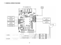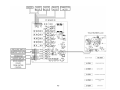
1
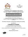
PSG 1700, Léon-Harmel Québec (Québec) G1N 4R9 Installation and operating instructions For the CADDY ALTERNA pellet furnace READ THE MANUAL THOROUGHLY BEFORE OPERATING THE FURNACE CERTIFIED ACCORDING TO CAN/CSA B366.1 M91,UL391 4TH EDITION 2006, CAN/CSA C22.2 NO.236-05, UL 1995 3RD EDITION 2003 FURNACE MODELS INCLUDED IN THIS MANUAL CADDY ALTERNA PELLET AND 15kW/20kW COMBINATION FURNACE Read these instructions carefully before installing and operating your furnace. CONGRATULATIONS! You have purchased one of the finest pellet or combination furnaces available on the market. We are confident that your furnace will provide years of comfort and safe operation. Please keep this document! 45406E 03/05/2009 SAFETY PRECAUTIONS • Do not operate your furnace if you smell smoke coming from it. Turn it off, monitor it, and call your dealer. • Never use gasoline, gasoline-type lantern fuel, kerosene, charcoal lighter fluid, or similar liquids to start or “freshen up” a fire in this furnace. Keep all such liquids well away from the furnace while in use. • • Keep foreign objects out of the hopper. • Do not throw this manual away. This manual has important operating and maintenance instructions that you will need at a later time. Always follow the instructions in this manual. • Do not unplug the furnace if you suspect a malfunction. Turn the furnace off, periodically inspect it, and call your dealer. Do not place clothing or other flammable items on or near the furnace. • Never try to repair or replace any part of the furnace unless instructions are given in this manual. All other work should be done by a trained technician. • The furnace will not operate during a power outage. If an outage does occur, check the furnace for smoke spillage and open a window if any smoke spills into the room. • • The viewing panel must be closed and latched during operation. • Do not operate the furnace if the flame becomes dark and sooty or if the burn pot overfills with pellets. Turn the furnace off, periodically inspect it, and call your dealer. • Disconnect power before performing any maintenance or repairs on the furnace. NOTE: Turning the furnace “off” does not disconnect all power from the furnace. Do not touch the hot surfaces of the heater. Educate all children of the danger of a high temperature furnace. Young children should be supervised when they are in the same room as the furnace. • Contact your local building officials to obtain a permit and information on any installation restrictions or inspection requirements in your area. Notify your insurance company of this furnace as well. • • The exhaust system must be completely airtight and properly installed. All vent connector joints must be sealed and fastened in accordance with the pellet pipe manufacturer's instructions to ensure consistent performance and avoid smoke and ash spillage. • This unit must be properly installed to prevent the possibility of a house fire. The instructions must be strictly adhered to. Do not use makeshift methods or compromise in the installation. Your furnace requires periodic maintenance and cleaning. Failure to maintain your furnace may lead to smoke spillage in your home. • Allow the furnace to cool before carrying out any maintenance or cleaning. Ashes must be disposed in a metal container with a tight lid and placed on a non combustible surface well away from the home structure. • This furnace must be connected to a standard 120 V., 60 Hz grounded electrical outlet. Do not use an adapter plug or sever the grounding plug. Do not route the electrical cord underneath, in front of, or over the furnace. • The exhaust system should be checked, at a minimum, at least twice a year for any build up of soot or creosote. 1 • This furnace is designed and approved for pelletized fuel only. Any other type of fuel burned in this heater will void the warranty and safety listing. • Stove Builder International Inc. grants no warranty, implied or stated, for the installation or maintenance of your furnace, and assumes no responsibility of any consequential damage(s). TABLE OF CONTENTS PELLET OR PELLET/ELECTRIC COMBINATION FURNACES ..................................................... 5 1. SAFETY RULES ..................................................................................................................................... 5 GENERAL REQUIREMENTS .................................................................................................................. 5 ODOUR FROM THE PAINT ..................................................................................................................... 5 ASH DISPOSAL ........................................................................................................................................ 5 CREOSOTE BUILD-UP AND REMOVAL .............................................................................................. 6 SOOT AND FLY ASH ............................................................................................................................... 6 SMOKE DETECTOR................................................................................................................................. 6 DOOR GLASS ........................................................................................................................................... 6 GLASS SPECIFICATIONS ....................................................................................................................... 6 ASH DRAWER .......................................................................................................................................... 7 3. APPLIANCE INSTALLATION ............................................................................................................. 7 REMOVING THE HOPPER AND BLOWER ASSEMBLY (IF REQUIRED) ......................................... 7 UNIT LOCATION AND FIXATION TO THE FLOOR .......................................................................... 10 CLEARANCES TO COMBUSTIBLE MATERIALS ............................................................................. 11 VENTING ................................................................................................................................................ 12 INSTALLATION CONFIGURATIONS ................................................................................................. 13 HORIZONTAL AND VERTICAL VENT CHART ................................................................................. 17 COMBUSTION AIR ................................................................................................................................ 18 INSTALLING PC BOARD #2 ................................................................................................................. 19 INSTALLING THE LCD USER INTERFACE ....................................................................................... 21 TEMPERATURE PROBE CONNECTION (RTD) ................................................................................. 22 ELECTRICAL ELEMENT CONNECTION............................................................................................ 22 THERMOSTAT (S) .................................................................................................................................. 23 FAN CONTROL....................................................................................................................................... 23 INSTALLATION OF AN AIR CONDITIONING UNIT......................................................................... 24 4. CONFIGURATION AND OPERATING INSTRUCTIONS ............................................................. 25 PC BOARD #2 (SYSTEM CONFIGURATION) ..................................................................................... 26 FIRST USE – GENERAL INFORMATION ............................................................................................ 26 MODES, OPTIONS, AND PROGRAMMING ........................................................................................ 26 The speeds............................................................................................................................................. 27 System Balancing .................................................................................................................................. 27 HEAT Mode (automatic heating).......................................................................................................... 27 COOL Mode (air conditioning) ............................................................................................................ 28 CIRC (air circulation) .......................................................................................................................... 29 MANU (manual heating) ...................................................................................................................... 29 LCD USER INTERFACE – OPERATION AND CONFIGURATION ................................................... 31 OPERATION TREE ................................................................................................................................. 32 CHOOSING THE MAXIMUM INPUT (BTU)...................................................................................... 33 CHOOSING THE PILOT LAG TIME................................................................................................... 33 2 FILLING-UP THE AUGER .................................................................................................................. 33 STARTING THE FURNACE ................................................................................................................ 33 CHOOSING MANUAL OR THERMOSTATIC MODE ........................................................................ 33 SELECTING LANGUAGE ................................................................................................................... 33 VIEW STATISTICS ............................................................................................................................... 34 CHANGING oF TO oC .......................................................................................................................... 34 GENERAL OPERATING GUIDELINES AND TIPS ............................................................................. 35 PELLETS AS HEATING FUEL ............................................................................................................ 35 EARLY SIGNS OF AN OVERFIRED FURNACE ................................................................................ 35 IF YOUR FURNACE RUNS OUT OF PELLETS ................................................................................. 36 REFUELING......................................................................................................................................... 36 SHUT DOWN PROCEDURE ............................................................................................................... 36 CHIMNEY FIRES ................................................................................................................................. 36 5. MAINTENANCE.................................................................................................................................... 37 MAINTENANCE OF THE EXCHANGERS AND BLOWER HOUSING ............................................. 37 VENTING SYSTEM MAINTENANCE .................................................................................................. 38 ASH REMOVAL AND VACCUM USE.................................................................................................. 38 CLEANING THE BURN POT ................................................................................................................. 39 CLEANING THE EXHAUST BLOWER HOUSING ............................................................................. 39 CLEANING THE COMBUSTION BLOWER ........................................................................................ 40 MAINTENANCE OF THE DISTRIBUTION BLOWER ........................................................................ 40 MAINTENANCE OF THE PRESSURE SWITCH TAP ......................................................................... 41 FILTERS .................................................................................................................................................. 41 DOOR GASKET MAINTENANCE ........................................................................................................ 41 RECOMMENDED MAINTENANCE SCHEDULE ............................................................................... 42 6. REPLACEMENT PARTS ..................................................................................................................... 43 DOOR GLASS ......................................................................................................................................... 43 GASKET .................................................................................................................................................. 43 AUGER MOTOR ..................................................................................................................................... 43 7. GENERAL WIRING DIAGRAM .................................................................................................... 44 8. WIRING DIAGRAM WITH OPTIONAL ELECTRICAL ELEMENT .......................................... 46 9. CADDY ALTERNA TECHNICAL DATA .......................................................................................... 47 GENERAL TECHNICAL DATA ............................................................................................................ 47 TECHNICAL DATA – ELECTRICAL ELEMENT ................................................................................ 47 TECHNICAL DATA – OTHER COMPONENTS ................................................................................... 47 PSG LIMITED LIFETIME WARRANTY .............................................................................................. 48 3 IMPORTANT NOTE: THE INSTALLATION OF THIS CENTRAL HEATING SYSTEM MUST BE PERFORMED BY A QUALIFIED TECHNICIAN. PSG RESERVES ITSELF THE RIGHT TO VOID ITS WARRANTY OR DENY TECHNICAL ADVICE IF THE FURNACE HAS NOT BEEN SOLD OR INSTALLED BY A PROFESSIONAL. REGISTER YOU WARRANTY ONLINE To receive full warranty coverage, you will need to show evidence of the date you purchased your furnace. Keep your sales invoice. We also recommend that you register your warranty online at www.psg-distribution.com Registering your warranty online will help us track rapidly the information we need on your furnace. 4 PELLET OR PELLET/ELECTRIC COMBINATION FURNACES The Caddy Alterna furnace was tested using the guidelines of the EPA Standard. To optimize the efficiency of your furnace, here are a few advices you should follow when installing or operating your Caddy Alterna. • Respect the local codes (when in doubt, consult your local dealer); • Make sure your furnace is installed according to the instructions on the certification label; • All controls and adjustments must be performed by a qualified technician. The blower speed must conform to the recommendations respect the recommended static pressure ranges in the warm air plenum of the furnace. 1. SAFETY RULES GENERAL REQUIREMENTS Make sure the chimney outlet and the pipes are clean and in good condition. DO NOT BURN WASTES OR FLAMMABLE LIQUIDS SUCH AS GASOLINE, NAPHTHA, MOTOR OIL, OR OTHER UNSUITABLE MATTERS. DO NOT USE CHEMICALS OR FLUIDS TO START THE FIRE. DANGER: Risk of fire or Explosion – Do not burn garbage, gasoline, drain oil or other flammable liquids. WARNING: Risk of fire - Do not operate with fuel loading or ash removal doors open. HOT WHILE IN OPERATION. KEEP CHILDREN, CLOTHING AND FURNITURE AWAY, CONTACT MAY CAUSE SKIN BURNS. WARNING THE ASH DRAWER AND EXCHANGERS ACCESS PANEL GET VERY HOT. DO NOT MANIPULATE WITH BARE HANDS. ODOUR FROM THE PAINT It is normal that smoke and odours emanate from the unit when you first light it. It is recommended to burn it at high rate and ventilate the building until the odours disappear. The smoke is not toxic. ASH DISPOSAL Ashes must be placed in a metal container with a tight fitting lid. The container should be stored outdoors, well away from combustible materials. This container should not receive any other type of waste. If the ashes are meant to be buried in soil, wait until all embers have thoroughly cooled before burying. 5 CREOSOTE BUILD-UP AND REMOVAL When fuel is burned slowly, it produces tar and other organic vapours which, when combined with moisture, form creosote. The creosote vapours condensate in a relatively cool chimney flue. As a result, creosote residues accumulate on the flue lining. N.B.: Store it in a dry place in order to obtain the minimum moisture rate and optimize the efficiency. Do not store fuel or combustible materials within the installation minimum clearances or the space required to reload the appliance and remove ashes. When ignited, creosote produces an extremely hot fire inside the chimney. In the first year of use, in order to avoid chimney fires, inspect the chimney system at regular intervals to determine a cleaning cycle. Depending on the type of pellet used and its quality, a semi-annual cleaning may be required. A yearly cleaning is mandatory. If a significant layer of creosote has accumulated, it must be removed immediately to eliminate the risk of chimney fire. Prepare an emergency procedure in case of a chimney fire. It is recommended to clean the heat exchangers thoroughly at the end of season in order to prevent corrosion. SOOT AND FLY ASH: Formation and Need for Removal – The products of combustion will contain small particles of fly ash. The fly ash will collect in the exhaust venting system and restrict the flow of the flue gases. The exhaust venting system should be inspected at least once every year to determine if cleaning is necessary. SMOKE DETECTOR We highly recommend the use of a smoke detector. It should be installed at least 15 feet (4,57 m) from the appliance. in DOOR GLASS Fly ash will cause the glass to become dirty after a full hopper of pellets has been burned. If you can still see a fire in the burn pot, you do not need to clean the glass immediately. However, when it becomes difficult to see the orange glowing produced by the fire, it is time to clean the glass. The frequency at which you clean the glass will depend on the type of fuel you use and thermostatic demand., You will have to clean it using a wet cloth and a fireplace cleaner. Clean the glass ONLY when the unit has cooled down. Do not use abrasive cleanser. Fireplace glass cleaners are available in most home centers and specialty hearth retailers. WARNING: Avoid knocking or scratching the glass. I could crack or break. GLASS SPECIFICATIONS The glass is made of 3/16” (5mm) thick Pyroceram. Do not operate your furnace with a broken glass, as this could seriously damage your furnace and cause ashes to be dispersed through the ductwork. You can purchase a replacement glass from your PSG dealer. 6 ASH DRAWER Your furnace is equipped with an ash drawer to collect ashes produced by the combustion of pellets. This drawer must not be left open during combustion as this may cause ash dispersion through the ductwork. The drawer must be emptied regularly. Once clean-up is completed, use an ash vac to carefully remove any ash around the drawer. Failure to perform this important step may cause ashes to be dispersed through the ductwork. It is important that the door and the ash drawer be kept closed while the appliance is in use. Maintain all gaskets in good condition; in case of deterioration, contact your dealer for a genuine replacement gasket. 3. APPLIANCE INSTALLATION REMOVING THE HOPPER AND BLOWER ASSEMBLY (IF REQUIRED) Should you need to install the furnace in an area that if difficult to access, both the hopper and blower assembly located at the back of the furnace may be removed. To do so, follow the instructions below. Hopper removal 1Remove the screws from the protection cover (keep the screws). Remove the cover. 7 2- Remove the screws from the hopper support (keep the screws). 3- Loosen the screws inside the hopper. Lift it and pull it backwards. 8 Blower removal Remove the screws around the blower assembly. C A 9 B The cold air ducting support is not installed on the blower assembly. It can be installed as per configurations A, B, or C. It is supplied in the hopper. UNIT LOCATION AND FIXATION TO THE FLOOR The furnace must be installed where outside air supply is sufficient for proper combustion. In airtight houses, it might be necessary to install an outside air intake (see COMBUSTION AIR SECTION). It is highly recommended that the unit be secured to the floor in order to prevent any situation where it could tip toward the back. Once you are certain of the furnace’s location and that all clearances to combustible materials are respected, you can secure the furnace to the floor. Follow the instructions below. 10 CLEARANCES TO COMBUSTIBLE MATERIALS N.B. This appliance must be installed according to the instructions on the unit’s certification label. DO NOT USE MAKESHIFT MATERIALS OR COMPROMISES IN THE INSTALLATION OF THIS UNIT. CEILING CEILING 60" 2" SEE NOTE* PLENUM 12" MIN 24" MIN 2' STATIC PRESSURE CHECK POINT MIN 0.20 W.C. LEFT WALL 24" EVEN IF THE REQUIRED CLEARANCES ARE 24’’ FOR MAINTENANCE, WE RECOMMEND 30’’ IN ORDER TO FACILITATE MAINTENANCE OF THE FURNACE. THE WARM AIR PLENUM SHOULD BE AT LEAST 24” HIGH. AIR FLOW WITHIN THE MAIN DUCT SHOULD REACH AT LEAST 700 FPM. NOTE : REFER TO THE MANUFACTURER’S OWNER’S MANUAL FOR CHIMNEY CLEARANCES. N.B. THE SIZE OF THE AIR RETURN DUCT SHOULD BE AT LEAST EQUAL TO THE SIZE OF THE COLD AIR PLENUM OPENING. The air return duct can be installed at zero clearance with the ceiling. FIRST 5 FEET OF DUCT INCLUDING WARM AIR PLENUM 2” (50mm) PLENUM AFTER THE FIRST 5 FEET 0” (0mm) REAR (INCLUDING CLEARANCE FOR MAINTENANCE) 24” (610mm) SIDES (INCLUDING CLEARANCE FOR MAINTENANCE) 24” (610mm) *FLOOR 0” (0mm) *The furnace can be installed on a combustible floor. A floor protector must cover all surfaces underneath the furnace. It must be prolonged 18’’ in front of the furnace and 8’’ on each side of the loading door. The floor protector must also cover all surfaces underneath the chimney connector and extending at least 2 inches on either side of the chimney connector. Plenum The plenums installed to the furnaces must be constructed of metal in accordance with NFPA 90B, 2-1.3. The plenum can be passed through the side wall with 2 inches of clearances around the plenum. 11 VENTING The Caddy Alterna is certified for use with a chimney certified to UL-103 or ULC S629M and a chimney type vent certified to UL-641 or ULC-S-609-M89 and ULC/ORD C441-M90, with 4” inner diameter. In Canada, we recommend that you use a listed pellet vent that meets the ULC S-609-M89 and ULC/ORD C441-M90 Standards. For the United States, we recommend that you use a listed pellet vent that meets the UL-641, 7th edition Standard. This unit can be vented in an existing chimney with the addition of a liner if the chimney is more than 4” in diameter. Class “A” chimney is not required. Where passage through an attic of roof space, closet or similar concealed space, of a floor, or ceiling, never use a chimney connector. Always use a chimney type vent or a chimney. Refer to the instructions provided by the vent or chimney manufacturer, especially when passing through a wall, ceiling, or roof, and the installation shall conform to CAN/CSA B365 and NFPA 211. Your venting system should have at least one foot of vertical rise for each foot of horizontal run. The total vertical rise on the outside wall should never be less than 3 feet (see Horizontal and Vertical Vent Chart). This is a pressurized exhaust system. All vent connector joints must be sealed and fastened in accordance with the pellet pipe manufacturer's instructions to ensure consistent performance and avoid smoke and ash spillage. DO NOT CONNECT THIS UNIT TO A CHIMNEY FLUE SERVING ANOTHER APPLIANCE. DO NOT INSTALL A FLUE DAMPER IN THE EXHAUST VENTING SYSTEM OF THIS UNIT. INSTALL VENT AT CLEARANCES SPECIFIED BY THE VENT MANUFACTURER. INSPECT AND CLEAN FLUES AND CHIMNEY REGULARLY 12 INSTALLATION CONFIGURATIONS A. HORIZONTALLY THROUGH WALL VERTICAL ROOF VENT 90 DEGREE ELBOW FOLLOW CHIMNEY OR VENT MANUFACTURER'S INSTRUCTIONS FOLLOW CHIMNEY OR VENT MANUFACTURER'S INSTRUCTIONS WALL THIMBLE WALL STRAP WALL THIMBLE 45 DEGREE ELBOW TERMINATION COLLAR WALL STRAP CLEAN OUT TEE CLEAN OUT TEE MIN. 2' MIN. 2' 13 90 DEGREE ELBOW FOLLOW CHIMNEY OR VENT MANUFACTURER'S INSTRUCTIONS 45 DEGREE ELBOW WALL THIMBLE TERMINATION COLLAR WALL STRAP CLEAN OUT TEE MIN 1' NOTE: Follow the vent manufacturer’s instructions. 1. Position furnaces, adhering to clearances. 2. Locate position of hole in wall; since most furnaces are installed in a basement, make sure that the hole in the wall is located above ground level. You will need to go up vertically for a few feet, and then go horizontally toward the wall. If the furnace is vented toward the back, a minimum vertical elevation of 2 feet is required to maintain an appropriate clearance with the hopper. If the furnace is vented toward the side, a minimum vertical elevation of 1 foot is required. 3. Always maintain 3” clearance from combustible materials. 4. Install a wall thimble as per the vent manufacturer’s instructions. 5. Attach enough piping to penetrate and extend at least 6” beyond exterior walls. To reduce the risk of smoke spillage and in order to favor a better draft,a minimum vertical rise of 3 feet is required on the outside wall. Furthermore, there should always be at least one foot of vertical rise for each foot of horizontal run (see Appendix A – Horizontal and Vertical Vent Chart). 6. Attach cap and seal outside wall thimble with non-hardening waterproof mastic. Termination should not be located so that hot exhaust gases can ignite trees, shrubs, or grasses or be a hazard to children. Exhaust gases can reach temperatures of 500ºF and cause serious burns if touched. Important: termination’s location: a) not less than 3 feet above any forced air inlet located within 10 feet; b) not less than 4 feet below or horizontally from, or one foot above, any door, window or gravity air inlet into any building; c) not less than two feet from an adjacent building and not less than 7 feet above grade when located adjacent to a public walkway. Other restrictions may apply, such as the need to maintain a minimum distance to a gas meter. US and Canadian Standards may vary. Consult the vent manufacturer’s instructions. 14 B. VERTICALLY WITH NEW CHIMNEY SYSTEM NOTE: Follow the vent manufacturer’s instructions. OPTION: In order to vent the furnace at the right location, a 45º elbow can be used to offset the pipe from the exhaust outlet toward the appropriate location underneath the ceiling. 1. Always maintain 3” clearance from combustible materials. When passing through additional floors or ceilings, always install firestop spacers. 2. After lining up for hole in roof, cut either a round or square hole in roof, always 3” larger all the way around pipe. Install upper edge and sides of flashing under roofing materials, nail to the roof along upper edge. Do not nail lower edge. Seal nail heads with non-hardening waterproof mastic. 3. Apply non-hardening, waterproof mastic where the storm collar will meet the vent. Slide storm collar down until it sits on the flashing. Seal and install cap. VERTICAL ROOF VENT ATTIC INSULATION SHIELD FOLLOW CHIMNEY OR VENT MANUFACTURER'S INSTRUCTIONS RADIATION SHIELD 15 C. VERTICALLY INTO EXISTING CHIMNEY SYSTEM As an alternative, the 4” vent can be run inside existing chimney to termination. NOTE: Follow the vent manufacturer’s instructions. 1. Have the chimney inspected by a qualified chimney sweep or installer to determine its structural condition. 2. You will need a pipe length equal to the chimney height from its point of insertion into the chimney. 3. Make sure that the flashing is ventilated. VERTICAL ROOF VENT D. VERTICALLY INTO EXISTING MASONRY CHIMNEY 6" 3" FOLLOW CHIMNEY OR VENT MANUFACTURER'S INSTRUCTION TOP PLATE OPTIONAL OUTSIDE AIR WALL THIMBLE CLEAN OUT TEE MIN. 2' 16 APPENDIX A HORIZONTAL AND VERTICAL VENT CHART If you plot your venting system configuration on this chart, your wall or roof termination should be within the grid. Possible Vertical vent length Possible Horizontal vent length (feet) Let’s imagine an installation consisting of a 4-feet vertical rise, a 90-degree elbow, followed by a 7-feet horizontal run through the wall, ending with a termination cap. This type installation is not acceptable. As you can see, the vent termination is clearly outside the allowed configuration zone on the chart. The venting system does not have at least one foot of vertical rise for each foot of horizontal run. Furthermore, it does not have a minimum elevation of 3 feet on the outside wall. Instead, if this installation consisted of a 4-feet vertical rise, a 90-degree elbow, followed by a 7-feet horizontal run through the wall, a clean our Tee, and a 3-feet rise ending with a termination cap, it would be acceptable. The installation would end be within the allowable configuration zone on the chart since it would have at least one foot of vertical rise for each foot of horizontal run. Furthermore, the outside wall vent would have a minimum rise of 3 feet. 17 COMBUSTION AIR When the furnace and the chimney are completely cold, it may be necessary to provide fresh air by opening a door or a window for a few minutes while lighting the fire. Take note that a house constructed or renovated in order to be airtight may lack the amount of fresh air necessary for the proper combustion of a solid-fuel heating appliance. In such a case, when starting up the fire, do not operate appliances that evacuate air outside the house, such as: - Range hood Air exchanger Clothes dryer Bathroom fan Ventilated central vacuum system A fresh air supply may be necessary to prevent solid fuel units from rejecting products of combustion into the house. The indications used to determine if an additional fresh air supply is necessary are not appropriate for all the situations. When in doubt, it is recommended to install a fresh air supply. A fresh air supply may be needed if: - Solid fuel units present anomalies, such as irregular draft, smoke return, bad combustion, and/or reversed draft (whether there is combustion or not); Existing solid fuel units such as a stove or fireplace release odours, heat badly, cause smoke returns, or reversed draft (whether there is combustion or not ); The opening of a window, even slightly, in calm weather (windless), eliminates every problem mentioned above ; The house is equipped with a tight vapour barrier and adjusted windows, and/or is equipped with an interior air mechanical evacuation device ; There is excessive condensation on the windows in winter; and The house is equipped with a ventilation system. If, according to these symptoms or other similar ones, there is insufficient combustion air, it is necessary to ensure an additional combustion air supply. Additional combustion air can be provided following the following methods, provided that they satisfy chapter 4 of the CSA B365 standard for Canada: • • • Direct connection: solid fuel units can be connected directly to a source of new combustion air only if they are certified for this kind of installation, which must respect the manufacturer’s instructions. The Caddy Alterna is approved with a fresh air supply connected directly to the unit. Indirect method: in the case of non-certified solid fuel unit for a direct connection with a source of new combustion air supply, new air is moved into a pipe located within 300mm (12 inches) or less of the solid fuel unit, in order to ensure its proper operation ; Mechanical ventilation system: if the house is equipped with a ventilation system (air exchanger or heat recovery), the ventilation system may provide sufficient auxiliary air to the solid fuel unit. Otherwise, the owner should be informed that the ventilation system may have to be rebalanced by a ventilation technician after the installation of the solid fuel unit. 18 NOTE: It is recommended to install an outside air inlet with a diameter of at least 5 inches in the room where the heating appliance is installed (see drawing below). It is preferable to choose a wall which is not exposed to dominant winds, depending on the conditions surrounding your house. In order to avoid condensation, the pipe should be insulated and its total length should be at least 10 feet. Insulated pipe (full length) Free air entry Fresh air intake P-trap Exterior INSTALLING PC BOARD #2 PC board #2 is used for the system configuration. Different locations can be chosen (right or left side). First, choose to install the PC board #2 on the left or on the right side of the furnace. Then, you must choose to install it directly on the hopper or on the bracket which will need to be secured to the hopper. Then, connect PCB#1 to PCB#2 using the black and white wires. Both wires must connect to the “WOOD DMPR” port on PCB#2. Finally, connect the blower and the thermostat to PC board #2. Refer to electric diagram for connection details. BLACK AND WHITE WIRES 19 BLACK AND WHITE WIRES PC BOARD #1 IS LOCATED BEHIND THIS PANEL 20 INSTALLING THE LCD USER INTERFACE The LCD user interface (touchscreen) is used for the system’s operation. It must be attached to the bracket already installed on the furnace. Then, connect PC board #1 to the LCD user interface. In order to do so, use the white cable already connected to PCB#1. Simply run the cable along the side of the furnace using the plastic clips supplied with the owner’s manual as shown below. PLASTIC CLIPS WHITE CABLE 21 TEMPERATURE PROBE CONNECTION (RTD) On the Caddy Alterna, a RTD has to be installed on the side of the appliance using the support provided (two holes are pre-drilled on the edge of the furnace). The RTD has to be connected to the PC board #2. The RTD is a sensor (probe type) that reads the temperature inside the hot air plenum. Refer to electric diagram for connection details. RTD SUPPORT RTD TWO HOLES PRE-DRILLED It is important that the RTD and the RTD support be properly fixed onto the plenum. WARNING: USE WIRING SUITABLE FOR 75OC ELECTRICAL ELEMENT CONNECTION The following instructions do not supersede the local code. The electrical element must be connected to the PC board #2 (see WIRING DIAGRAM). For security reasons, the electrical element has a manual reset thermostatic sensor that is located inside the electrical unit. If the temperature of the electric unit exceeds the high limit, the thermostatic sensor will disengage the elements. To reactivate, press the red “manual reset” button on the thermostatic sensor (L-170 thermodisc) after finding and fixing the problem that has caused the unit to overheat (static pressure too high, fan breakdown, etc.) INSIDE VIEW OF THE ELECTRIC ELEMENT Red button manual reset L-170 Thermodisc RESET 22 The PELLET / ELECTRIC combination model uses two thermostats: one thermostat controls the electric heating, and the other one controls the pellet heating. When the call for heat cannot be satisfied by pellet heating, the electrical element will automatically take over to maintain the house at the temperature set on the electrical element’s thermostat. Therefore, under normal bi-energy use, you should set the pellet system thermostat 2o to 4o higher than the electric system thermostat; the bigger the gap, the more the pellet heating will contribute to the overall heating needs. THERMOSTAT (S) Pellet furnace only The thermostat must be installed on an inside wall and located where it is not likely to be affected by the draft coming from an air outlet. It must be installed at a minimum of 55 inches above the floor. Combination pellet-electric The combination model uses two thermostats which must be located at the same height from the floor. If the main thermostat (pellet) calls for heat and that demand is not satisfied with the energy supplied by the pellet, the optional heating unit (electrical element) will take over and will maintain the home’s temperature at the setting programmed on the second thermostat (e.g. the option’s thermostat). The main thermostat must be connected to the “WOOD MECH” port on the PC board. The electric option’s thermostat must be connected to the “USER MECH” port on the PC board. The “WOOD24VAC” & “USER24VAC” ports are only necessary when connecting an external appliance that shares the furnace blower (example : AC, heat pump). FAN CONTROL We recommend that the HEAT mode be programmed for the Caddy Alterna (this is done with the PC board #2). Under the HEAT mode, the distribution blower uses various speeds that are controlled by the PC board #2 based on the hot air plenum temperature. The plenum temperature is read by the RTD temperature probe. The manufacturer’s programmed settings should provide the most efficient operation for a majority of installations. The PC board #2 also has a manual mode (“MANU” – consult the MODES section of this manual). Under the manual mode, the Caddy Alterna operates as a conventional furnace. That is, the distribution blower starts at the speed programmed in the PC board #2 (one single speed) based on only one temperature point read by the RTD probe inside the hot air plenum. The adjustment of all controls must be performed by a qualified technician. In order to obtain a continuous air circulation during summer, you simply need to change the PC board #2 modes to “CIRC”. To do so, consult the MODES section of this manual. It is not recommended to let the blower run on the continuous mode when heating with pellet since the pellet furnace must reach a certain temperature before the blower starts in order to operate efficiently. 23 INSTALLATION OF AN AIR CONDITIONING UNIT The Caddy Alterna pellet furnace has been tested with an optional air conditioning unit. If this option is chosen, we recommend an installation as per the graphic provided below. This installation will provide the most efficient and safe operation of the air conditioning unit using the distribution blower of the Caddy Alterna furnace during summer. In order to complete the installation of an air conditioning unit, the main thermostat must be a “heat/cool” type. Furthermore, the PC board #2 of the furnace must be in a COOL mode and the desired distribution blower speed must be programmed (see MODES section for complete instructions). It must be noted that upon thermostatic demand for cooling, the distribution blower will start immediately. The capacity and characteristics of the air conditioning unit that has been tested for the Caddy Alterna are stated below. The use of another brand with similar capacity and characteristics is adequate. Condenser brand: Goodman GSX13036 Capacity: 4 ton Coil type: Type A, CAUF (uncased indoor coil). Damper A/C coil Damper Recommended Installation with an AC unit 24 4. CONFIGURATION AND OPERATING INSTRUCTIONS Before you configure your system and learn how to operate it, it is important to note that your Caddy Alterna is equipped with 3 main electronic components: PC board #1, PC board #2, and the LCD user interface. PC board #1 is already attached to the furnace. PC board #1 will only need to be accessed if the fuses need to be replaced. PC board #2 is used for the system configuration. More precisely, it is used for the following: - Programming the different modes (HEAT, MANU, CIRC, and COOL); Choosing the selections (TEMP, UNIT) for HEAT mode and (TEMP, UNIT and FAN) for MANU, CIRC or COOL mode; Connecting the RTD temperature sensor; Connecting the thermostats; Connecting the electrical element option. The LCD user interface is used for the system’s operation. More precisely, the LCD interface is used for the following: - - Choosing the maximum BTU input; Choosing the pilot mode lag time; Filling up the auger; Starting the furnace; Turning the furnace off; View the flue temperature; Choosing the manual or thermostatic mode; Select language; View statistics; Changing oF to oC; Troubleshooting the unit. PC board #2 (system configuration) – See page 26 25 PC BOARD #2 (SYSTEM CONFIGURATION) On the Caddy Alterna furnace, a new electronic control was developed. This system is more polyvalent. All connections are done from the PC board #2. There are connector ports available for all components and options. Under the HEAT mode, a logic was developed to provide you with the best comfort and efficiency.When you are heating with pellets, the distribution blower starts at speed #1 based on a preselected temperature programmed into the PC board #2 (this temperature is called the KIP – Kick-in Point). The temperature is read by the RTD probe located inside the hot air plenum. As the temperature continues to rise inside the hot air plenum, the PC board #2 changes the speed of the blower to speed #2. This speed should maintain the most efficient temperature (BEP – Best Efficiency Point) inside the hot air plenum. If the optional electrical unit provides the heat, the BEP is set at 145F. Whenever the temperature inside the hot air plenum continues to rise above the BEP, the PC board #2 selects a higher speed in order to stabilize the temperature into the ducting system and therefore maintain the BEP. In the case of the electrical option, the blower starts as soon as that there is a request for heat from the option’s thermostat. In other words, for security reasons, the distribution blower does not wait for a minimum temperature to be reached inside the hot air plenum before starting. However, the rest of the logic remains the same. That is, for as long as there is a heat demand, the PC board #2 will vary the distribution blower’s speed in order to maintain the BEP inside the hot air plenum. FIRST USE – GENERAL INFORMATION The RTD probe reads the temperature inside the hot air plenum and plays the same role as a mechanical fan limit control found on most conventional furnaces. The main difference is that the RTD is connected to a PC board #2. It is an electronic fan limit. First, you must configure your PC board #2. During the start-up, the PC board #2 will display some information such as the name of the company as well as the version of the program. MODES, OPTIONS, AND PROGRAMMING Your PC board #2 is equipped with four operating modes: HEAT (automatic heating), COOL (air conditioning), CIRC (recirculation), and MANU (manual heating). You can pass from one mode to the other by pressing on the arrows buttons. For each mode, some selections are available. A definition is provided below (see: “The Selections”). 26 The speeds Your furnace is equipped with a 4-speed blower. Using the PC board #2, we have created 6 functional speeds. Refer to Table 2 below for the various speed configurations. Table 2 – The Speeds Speed 1 2 3 4 5 6 Corresponding data CFM STATIC PRESSURE Blower speed #1 using 90V Blower speed #1 using 115V Blower speed #2 using 98V Blower speed #2 using 115V Blower speed #3 using 115V Blower speed #4 using 115V 400 700 775 875 1075 1175 0.2’’ W.C. 0.2’’ W.C. 0.2’’ W.C. 0.2’’ W.C. 0.2’’ W.C. 0.2’’ W.C. The Wall Thermostat You must connect your PC board #2 to a wall thermostat. If your furnace is equipped with an auxiliary electrical heating option, you must have two wall thermostats. The main thermostat must be connected to the “WOOD MECH” port on the PC board. The electric option’s thermostat must be connected to the “USER MECH” port on the PC board. The “WOOD24VAC” & “USER24VAC” ports are only necessary when connecting an external appliance that shares the furnace blower (example : AC, heat pump). System Balancing It is important to call upon a professional installer for the installation of the furnace and the ducting system configuration. Certain check-ups must be performed and certain rules must be respected in order not to damage the blower. When all components are installed on the furnace and the ducting system is connected to the various rooms of the house, you must balance the ducting system. In order to do so, start the furnace blower by selecting the recirculation mode (CIRC). Then, in the FAN section, use the arrows to select speed #4 (refer to Table 2). It is important to respect the velocity in the main duct, the secondary ducts, as well as the velocity at the room outlets. The static pressure of your system must be adjusted to at least 0.2 IN.W.C. and must not exceed 0.5 IN.W.C. Finally, make sure that you never exceed the maximum blower current. Velocity in the main duct should reach at least 700 fpm. HEAT Mode (automatic heating) Operation When the temperature in your house is below the value at which your wall thermostat is programmed, a signal is sent to your furnace through the PC board #2, activating the maximum pellet feed rate. The RTD temperature probe, located inside the hot air plenum of your furnace, reads the plenum temperature continuously. When the temperature reaches the start-up value (KIP – Kick-in Point), the distribution blower starts functioning at the minimum speed. Thereafter, the blower increments its speed until it reaches the best efficiency point (BEP) determined by the manufacturer. If the temperature inside the hot air plenum exceeds the limit determined by the manufacturer, the blower automatically selects the maximal speed in order to cool off the furnace which will change to pilot mode. When the temperature returns to a safe level, the blower speed gradually returns to the speed required to maintain the BEP. 27 Programming Make sure that your wall thermostat is well connected to the PC board #2. The main thermostat must be connected to the “WOOD MECH” port on the PC board. The electric option’s thermostat must be connected to the “USER MECH” port on the PC board. The “WOOD24VAC” & “USER24VAC” ports are only necessary when connecting an external appliance that shares the furnace blower (example : AC, heat pump). In the MODE menu, select HEAT by pushing the SELECT button. Then, using the arrows buttons, choose from the different selections: TEMP, or UNIT. Consult the “Selections” section in order to obtain a complete definition of the terms TEMP, and UNIT. When your choice is made, press SELECT. Then, use the arrows to make the appropriate adjustment. Press SELECT to memorize your adjustment. To change the selection (TEMP, or UNIT), push an arrow button. To go back to the main menu (HEAT, COOL, CIRC, MANU), push on the MODE button. After two minutes of inactivity on the keyboard, the display will shut itself off. COOL Mode (air conditioning) Operation If an air conditioning unit is installed, the PC board #2 will have to be connected to a dual-function wall thermostat (e.g. “heat/cool”) in order to synchronize the start of the furnace blower with the start of the air conditioning condenser. A switch installed on the PC board #2 will modify the reading of the wall thermostat’s signal. Upon receiving the wall thermostat’s signal, the furnace blower will start functioning at the speed selected by the user. Programming Make sure that your wall thermostat is well connected to the PC board #2. The main thermostat must be connected to the “WOOD MECH” port on the PC board. The electric option’s thermostat must be connected to the “USER MECH” port on the PC board. The “WOOD24VAC” & “USER24VAC” ports are only necessary when connecting an external appliance that shares the furnace blower (example : AC, heat pump). In the MODE menu, select COOL by pushing the SELECT button. Then, using the arrows buttons, choose from the different selections: TEMP, UNIT, or FAN. Consult the “Selections” section in order to obtain a compete definition of the terms TEMP, UNIT, and FAN. When your choice is made, press SELECT. Then, use the arrows to make the appropriate adjustment. Press SELECT to memorize your adjustment. To change the selection (TEMP, UNIT, or FAN), push an arrow button. To go back to the main menu (HEAT, COOL, CIRC, MANU), push on the MODE button. After two minutes of inactivity on the keyboard, the display will shut itself off. 28 CIRC (air circulation) Operation This mode is used to circulate air during summer. Thus you will benefit from your ducting system to circulate fresh air from your basement throughout the house. Programming In the MODE menu, select CIRC by pushing the SELECT button. Then, using the arrows buttons, choose from the different selections: TEMP, UNIT, or FAN. Consult the “Selections” section in order to obtain a compete definition of the terms TEMP, UNIT, and FAN. When your choice is made, press SELECT. Then, use the arrows to make the appropriate adjustment. Press SELECT to memorize your adjustment. To change the selection (TEMP, UNIT, or FAN), push an arrow button. To go back to the main menu (HEAT, COOL, CIRC, MANU), push on the MODE button. After two minutes of inactivity on the keyboard, the display will shut itself off. MANU (manual heating) Operation The mode allows you to run your system manually without taking into account the blower variation around the BEP (Best Efficiency Point). When the temperature in your house will go below the value at which your wall thermostat is programmed, a signal will be sent to your furnace through the PC board #2, activating the pellet feed rate to its maximum. The RTD (temperature sensor), located in the hot air plenum of your furnace, will read the plenum temperature. When the temperature reaches the start-up value selected by the user (KIP), the blower will start functioning at the speed selected by the user. If the temperature exceeds the limit determined by the manufacturer, the blower will automatically select the maximal speed in order to cool off the furnace. When the temperature returns to a safe level, the blower will return to the speed selected by the user. Programming Make sure that your wall thermostat is well connected to the PC board #2. Make sure that the right port has been selected based on the type of thermostat. In the MODE menu, select MANU by pushing the SELECT button. Then, using the arrows buttons, choose from the different selections: TEMP, UNIT, or FAN. Consult the “Selections” section in order to obtain a compete definition of the terms TEMP, UNIT, and FAN. When your choice is made, press SELECT. Then, use the arrows to make the appropriate adjustment. Press SELECT to memorize your adjustment. To change the selection (TEMP, UNIT, or FAN), push an arrow button. To go back to the main menu (HEAT, COOL, CIRC, MANU), push on the MODE button. After two minutes of inactivity on the keyboard, the display will shut itself off. The Selections TEMP (Temperature) By pushing the arrows, you will see the current temperature inside the main hot air plenum of your furnace. After two minutes of inactivity on the keyboard, the display will shut itself off. The TEMP selection has no impact on the operation of the furnace. It is offered as a practical way for an installer or a technician to quickly obtain the temperature inside the hot air plenum under the HEAT or MANU modes if a problem arises and the temperature must be known in order to trouble shoot the furnace. 29 UNIT (measuring unit) By pushing the arrows, you will select the measuring unit that you wish to use (Fahrenheit or Celsius). Thereafter, temperatures will be displayed according to your selection. After two minutes of inactivity on the keyboard, the display will shut itself off. The UNIT selection has no impact on the operation of the furnace. It is simply a preference chosen by the technician or the user of the product.. FAN (blower speed) Using the arrows, increase or decrease the blower speed. You can choose from six preselected speeds. This selection is very important for the modes COOL, MANU, or CIRC. There is a choice of 6 different speeds. Under the COOL mode, the speed selected is the speed at which the distribution blower will work when a cooling demand will be sent by the thermostat. Under the MANU mode, it is the speed at which the distribution blower will work when a heating demand will be sent by the thermostat and that the hot air plenum will have reached its kick-in temperature (KIP). Under the CIRC mode, it is the speed at which the distribution blower will run to circulate the air inside the house during summer. The CIRC mode will also be used by the technician to manually select speed #4 in order to balance the system upon installation of the furnace. Note: The FAN selection is not necessary under the HEAT mode because it is the PC board #2 that automatically chooses the speed at which the distribution blower runs in order to maintain the BEP inside the hot air plenum. 30 LCD USER INTERFACE – OPERATION AND CONFIGURATION Manual mode main page Thermostat mode main page = Indicates that the furnace status is on manual mode = Indicates that the furnace status is on thermostat mode. The green waves indicate that the thermostat is on demand. The waves will disappear once the desired temperature is reached. = Indicates the flue temperature , , , , = Indicates the BTU setting. Starting from the smallest flame to the biggest flame, the respective BTUs are : 17,000 – 60,000 – 80,000 – 100,000 or 120,000. Pressing on the desired BTU setting (flame) will change the color of the flame to green to show its activation. , = Indicates whether the furnace is on or off. If the flame is shown in the middle of the button, the furnace is on. If the flame is not shown in the middle of the button, the furnace is off. = This button leads to the menu screen = This button is used to fill up the auger. Pressing once will active the auger for 1 minute. = The hourglass indicates how long the pilot will be on before shutting down the unit. The setting chosen by the user appears under the hourglass. 31 OPERATION TREE Selects the language displayed on the LCD interface (french, english, or spanish) Selects the pilot mode (30 minutes, 45 minutes, always on) Selects the scale of temperature displayed on the LCD interface (Celcius or Faranheit) Menu Screen This is a non-interactive page. It will help the user troubleshoot the unit if needed (verifies the status of security sensors, lists the number of error codes and enables the user to activate motors independently). This page is locked with a security code. It will help the user troubleshoot the unit if need be (only for customer/technical service). Returns to main menu page Selects the mode at which the furnace operates (thermostatic or manual) Returns to main page. Selects the BTU input at which the furnace operates (60000, 80000, 100000, or 120000). 32 CHOOSING THE MAXIMUM INPUT (BTU) Your Caddy Alterna has an input that can reach up to 120,000 BTU. Since the efficiency of the furnace is 90%, the output can be calculated by multiplying the input by 0.90. In order to reduce cycling of the furnace, the BTU input can be adjusted by the installer based on the size of the house. There are five selections to choose from. The factory default BTU is programmed at 100,000. In order to change the BTU input, refer to the operation tree at the beginning of this section. CHOOSING THE PILOT LAG TIME When the temperature set on the wall thermostat is achieved, a signal is sent to your furnace. The furnaces then put itself in a pilot mode. On the pilot mode, the furnace operates at its lowest feed rate. It feeds approximately 2 pounds of pellets per hour, the equivalent of 17,500 BTU. You can select the pilot lag time. The pilot lag time is the time the furnace will wait on the pilot mode before shutting down if there is no more thermostatic heat demand. You can choose between 30 minutes, 45 minutes, one hour, and continuous. If you choose continuous and there is no heat demand, the furnace will stay on pilot until there is no more pellets in the hopper. The factory default lag time is programmed at one hour. In order to change the pilot lag time, refer to the operation tree at the beginning of this section. FILLING-UP THE AUGER When the furnace runs out of pellets, it empties the auger housing. In order to start the furnace again, you need to fill the auger in order to bring pellets to the burn pot for ignition. This process takes approximately 3 minutes and a function has been programmed on the LCD interface. In order to fill the auger, refer to the operation tree at the end of this section. When you press the “feed auger” icon, the auger will turn continuously for one minute. Therefore, if the auger is completely empty, you may need to press the “feed auger” button up to 3 times before you completely fill the auger and burn pot with pellets. STARTING THE FURNACE Once the hopper is full of pellets, the auger is filled, and the firebox door is closed, you can start the furnace. In order to start the furnace, simply press the round “on/off” icon on the main status page. CHOOSING MANUAL OR THERMOSTATIC MODE In the manual mode, your furnace will run continuously at the BTU input selected until the furnace runs out of pellets. In most cases, however, you will be using your furnace on the thermostatic mode. That is, the furnace will only operate at its maximum BTU input when the thermostat is on demand. In order to change from thermostatic mode to manual mode (and vice-versa), refer to the operation tree at the beginning of this section. SELECTING LANGUAGE You can choose between English, French, and Spanish. In order to change the language, refer to the operation tree at the beginning of this section. 33 VIEW STATISTICS Numerous statistics can be viewed, such as the furnace run time (i.e. the number of hours the furnace has operated since it was first used). In order to view statistics, refer to the operation tree at the beginning of this section. CHANGING oF TO oC You can choose between oF and oC. In order to change from oF to oC and vice-versa, refer to the operation tree at the beginning of this section. 34 GENERAL OPERATING GUIDELINES AND TIPS PELLETS AS HEATING FUEL Your furnace has been designed to burn various types of pellets. Each type of pellet has its properties and will burn differently. The ash produced can also vary greatly. The different types of pellets that have been tested in the Caddy Alterna were made of the following types of biomass: Wood pellets Wood pellets, whether made of hard or soft wood, are easy to burn. They pellets used are the same type as the ones used in most pellet stoves. They should produce a fairly small quantity of ash. Wood and hay pellets Pellets made of wood and hay will produce more ash than straight wood pellets. The wood and hay pellets that have been tested in your Caddy Alterna consisted of 1/3 hay and 2/3 wood. Make sure that any wood and hay pellets you put in your Caddy Alterna respect that mix (+/- 10%). Bark pellets 100% bark pellets produce a hard crust that will be pushed into the ahs drawer. Their ash content is very high. If you burn 100% bark pellets, make sure that the crust forming in front of the burn pot breaks and falls into the ash drawer. Ignition may be a bit more difficult and it is possible that the furnace needs a second ignition cycle to properly light the bark pellets. Switchgrass pellets The ash content of switchgrass pellets may vary depending on when this type of biomass is harvested. Switchgrass will burn very clean. A crust will form in front of the burn pot. It should break easily and fall into the ash drawer. The crust is light and friable. It will occupy quite a bit of volume into the ash drawer. For this reason, if you are not present to empty the ash drawer, you should only fill 50% of the hopper. Do not operate the stove if there is an abnormal air leakage into the stove, such as through deteriorated gaskets or cracked or broken glass. Do not operate the stove without a door gasket. Leakage can result in overheating, or in very airtight homes, could possibly cause smoking into the room. Smoke may contain carbon monoxide, which is poisonous, and in sufficient quantities, and can cause a health hazard or even death. EARLY SIGNS OF AN OVERFIRED FURNACE If you see a lazy, very high orange flame inside the firebox, it may be a signed thatyour furnace is overfired and getting too hot. Under normal conditions, the flame should be about 12 inches high and it should be lively. It should have a bright, yellow color. Too much restriction in the venting system and a blocked heat exchanger are the primary causes of an overfired furnace. If the furnace becomes too hot, it will activate the thermistor located on the 35 exhaust box beside the exhaust blower. If this occurs, a “UNIT OVERHEAT” codewill appear on the LCD display. If you obtain a “UNIT OVERHEAT” code, it is a sign that your furnace is getting dangerously hot. You need to clean the heat exchanger and verify the venting system. If you get a “UNIT OVERHEAT” code again, call your dealer. IF YOUR FURNACE RUNS OUT OF PELLETS If your furnace runs out of pellets, the fire goes out and the auger motor and blowers will run until the furnace cools down. This will take a few minutes. After the furnace’s components stop running, a warning message “NO FUEL” will appear on the LCD display. button until pellets arrive to the To restart the furnace, press the “RESET” button, refill the hopper, and press the burn pot. Press the round “ON/OFF” icon on the main status page to start the furnace. REFUELING We recommend that you not let the hopper go completely empty. Upon reloading, if the hopper lid stays for open more than 3 minutes, a warning code ‘’HOPPER LID OPEN’’ will appear on the LCD display. To restart, press the “RESET” button, and then press the round “ON/OFF” icon on the main status page to start the unit. KEEP HOPPER LID CLOSED AT ALL TIMES EXCEPT WHEN REFILLING. THE HOPPER MAY BE FILLED WHILE THE FURNACE IS OPERATING. DO NOT OVERFILL HOPPER. SHUT DOWN PROCEDURE Turning your furnace off is a matter of pressing the round “ON/OFF” icon on the main status page. The little flame at the center of the icon will disappear when the furnace is turned off. The blowers will continue to operate while the furnace is cooling down. CHIMNEY FIRES This might occur when the fire gets extremely hot. Burning inadequate pellets ignite the creosote residue accumulated in the evacuation flue system. The usual signs are: 1. Rumbling. 2. The flue gets extremely hot (red). 3. Flames or sparks are coming out of the chimney. In case of a chimney fire, call your local fire department immediately and sprinkle the roof around the chimney with water. Make sure that the furnace door is closed (if necessary, lower the thermostat starting point). If the fire gets uncontrollable due to an improper use or because the draft is too strong, follow the same procedure as in a chimney fire. LOCAL FIRE DEPARTMENT Phone number: ___________________________________ 36 5. MAINTENANCE MAINTENANCE OF THE EXCHANGERS AND BLOWER HOUSING The exchangers should be inspected regularly during the burning season. Easy access is provided: Before cleaning the six exchanger pipes, remove the front cover located above the combustion chamber (see drawing below). It is important to start from the top and finish at the bottom. Using the scraper, clean the six exchanger pipes. The accumulated dirt in the lateral exchangers must also be cleaned up. To do so, start by removing the side panel on the left side of the furnace. You will have access to 3 clean out traps. Using an ash vac will be the most efficient way to collects ashes that may have accumulated. Please note that you do not need to repeat the same steps on the right side of the furnace. The lateral exchangers can easily be reached on either side of the furnace. One of the clean out traps will give you access to the blower housing. Be very careful to not damage the blower impellers when you clean the inside of the blower housing. Finish by putting back all clean out traps and closing the access panels. Should one of the clean out trap gaskets be damaged, it is very important that you replace it in order to prevent leakage of flue gases inside the ductwork, Clean out trap Clean out trap 37 Clean out trap VENTING SYSTEM MAINTENANCE REGULARLY EXAMINE THE FLUE PIPES, THE JOINTS, AND THE SEALING TRIMS TO ENSURE THAT THE SMOKE AND THE COMBUSTION GASES ARE NOT TRANSPORTED INTO THE AIR DUCTING SYSTEM. The most efficient method to sweep the venting system is using a 4-inch pellet brush. Brush downwards so ash, soot and creosote residues will come off the inner surface and fall at the bottom of the venting system where they can be removed easily. The chimney must be in good condition and kept clean. If a significant layer of creosote has accumulated, it must be removed immediately to eliminate the risk of a chimney fire. CAUTION: CLEANOUT OF THE HEAT EXCHANGER, FLUE PIPE, CHIMNEY, AND DRAFT INDUCER IF USED, IS ESPECIALLY IMPORTANT AT THE END OF THE HEATING SEASON TO MINIMIZE CORROSION DURING THE SUMMER MONTHS, CAUSED BY ACCUMULATED ASH. ASH REMOVAL AND VACCUM USE In order to remove ashes form the ash drawer, simply remove the door access in front at the bottom of the furnace, open the other door access and remove the ash drawer. Once the ashes have been removed, you should take this opportunity to thoroughly vaccum around the ash drawer. This will prevent ashes from being dispersed into the air ducts. We suggest using a vacuum designed for ashes. Some regular vacuums and shop vacs leak ash into the room. Your vacuum or shop vac may have a special filter or bag available to eliminate this leakage. ASH DRAWER 38 CLEANING THE BURN POT The burn pot should be kept clean and its ports should not be plugged with combustion residues. Cleaning the burn port is simple. To do so, you may use the scraper supplied with unit (in the hopper) or release the clip in front of the burn pot. Then, remove the burn pot by pulling on it. CLEANING THE EXHAUST BLOWER HOUSING The exhaust blower should be removed for inspection and cleaned once a year. To do so, remove all screws around the access trap . Then, vacuum thoroughly inside the blower housing. Be very careful not to damage the blower impellers. 39 CLEANING THE COMBUSTION BLOWER The combustion blower should be removed for inspection and cleaned twice a year. To do so, remove all wing nuts below the air intake system. Vacuum thoroughly. MAINTENANCE OF THE DISTRIBUTION BLOWER The two motor bearings must be lubricated once a year using non detergent SAE 20 oil (Marathon motor only). DO NOT OVERLUBRICATE 40 MAINTENANCE OF THE PRESSURE SWITCH TAP Ashes may accumulate on inside tip of the pressure switch probe connector. Use a mesh pad or wire brush to clean the connector and blow inside the tube to make sure it Is free of obstruction. PRESSURE SWITCH TAP FILTERS The furnace must not be operated without filters. In order to efficiently and safely operate your pellet heating system, you have to ensure a regular maintenance. This means that the air filters must be replaced regularly; use the same size and same type as the original filters. High efficiency 2-ply, 3-ply, or 4-ply filters are recommended. Filters dimensions Caddy Alterna: 16” x 20” filter DOOR GASKET MAINTENANCE It is important to maintain the door gasket in good condition. After a while, the gasket might sag; a door adjustment may then be required. If the door adjustment is not sufficient, replace the door gasket with a genuine one. If the furnace door is not properly sealed, combustion gases may be dispersed into the air ducts. Door adjustment procedure: 1. Unscrew completely the locking pin (see picture below). Locking pin 2. To increase the pressure of the door on the gasket, turn the handle counter clockwise; to decrease the pressure of the door on the gasket, turn the handle clockwise until desired pressure is attained. 3. Then, screws back the locking pin about 1/4” deep and make sure you lock it in place with the nut. 41 RECOMMENDED MAINTENANCE SCHEDULE Use this as a guide under average-use conditions. Components Burn Pot Glass Weekly or after +/- 500 pounds Brush Clean Twice a year or after +/- 2 tons Scrape and Vacuum* Heat Exchanger Tubes Exhaust Channels (through access traps) Ash Drawer Combustion Chamber Exhaust Blower Combustion Blower Pressure Switch Tap Venting System Gaskets Filters Hopper Annually or per 4 tons of pellets Vacuum* Empty / Vacuum Vacuum Vacuum / Brush* Vacuum* Vacuum* Brush* Inspect Inspect Inspect Sweep Empty / Vacuum *Cleaning frequency may vary depending on the type of fuel used. Fuel with a higher ash content will increase cleaning frequency. 42 6. REPLACEMENT PARTS Your PSG furnace is designed to burn clean and requires regular maintenance. It is recommended to conduct a visual inspection at least once a month to uncover any damage to the unit. Any defect must be repaired without delay using genuine PSG replacement parts. You can find a complete list of replacement parts in our website at www.psg-distribution.com. DOOR GLASS • • • • • Inspect the glass regularly to detect any glass failure. If you find any defect, stop using the furnace immediately. Never operate a pellet furnace with a broken glass. If you have to change your door glass, you must use Pyroceram 3/16” (5mm) thick. Use genuine parts sold by a PSG authorized dealer. To replace the glass, remove the screws that hold the glass retainers in place. Removed these retainers and replace the defective glass; the glass gasket should be replace at the same time. To put back in place, reverse the procedure. Do not use abrasive cleanser. Special cleansers for wood fireplaces are available in any good hardware store or specialty hearth retailer. Clean glass ONLY when the unit has cooled down. GASKET We recommend replacing gasket that seals the door once a year, in order to maintain a good control of the combustion for maximum efficiency and security. To replace your door gasket, remove the old gasket and adhesive. Clean the surface thoroughly, apply a high-temp adhesive/silicone (650oF) sold for that particular use, and put the new gasket onto the door. Wait for at least 12 hours before lighting your furnace. AUGER MOTOR If you must replace the auger motor, you need to remove its lid. To do so, remove the screws located around the lid. Unplug the wiring connexions from the auger motor. To remove the auger motor, loosen the shaft screw. 43 7. GENERAL WIRING DIAGRAM 44 45 8. WIRING DIAGRAM WITH OPTIONAL ELECTRICAL ELEMENT CADDY ALTERNA PELLET/ELECTRIC COMBINATION FURNACE CONTROL PCB FUSE TERMINAL HEATING ELEMENT THERMODISC SEQUENCER 240V TERMINAL BLOCK L1 N L2 46 9. CADDY ALTERNA TECHNICAL DATA CADDY ALTERNA A B C D E F G H "G" "F" "E" 56 ¼” 26 ¼” 47” 21 ¼” 22” "C" 22” 29 ½” "H" 16 ¼” FLUE PIPE WEIGHT 4” "D" "A" "B" 500 lbs GENERAL TECHNICAL DATA MODEL DIRECT DRIVE FAN MOTOR FLOW SPEED TEMP VAR. (CFM) BTU INPUT O ( F) STATIC PRESSURE (PELLET) MIN. MAX. FILTER (1) IN.W.C. CADDY ALTERNA G-10 1/2HP 4 1650 110 120,000 0,2 0,5 16” x 20” X 1” TECHNICAL DATA – ELECTRICAL ELEMENT MODEL 15 kW 20 kW PELLET OUTPUT (CFM) 1650 1650 1650 TEMP. VAR. O ( F) 65 75 110 BTU/HR 51,180 68,240 115,000 AMPS TOTAL 65 85 6 BREAKER REQUIRED 100 amps 125 amps 15 amps TECHNICAL DATA – OTHER COMPONENTS Igniter: lda00068, 500 Watts, 120 volts Fuses: Midget 30 amps Time-Delay (Littelfuse) 47 FEEDER GAUGE 4 3 14 VOLTAGE SINGLE PHASE 120/240 120/240 120 ELEMENTS QTY 3 x 5 kW 4 x 5 kW N/A PSG LIMITED LIFETIME WARRANTY The warranty of the manufacturer extends only to the original consumer purchaser and is not transferable. This warranty covers brand new products only, which have not been altered, modified nor repaired since shipment from factory. Proof of purchase (dated bill of sale), model name and serial number must be supplied when making any warranty claim to your PSG dealer. This warranty applies to normal residential use only. Damages caused by misuse, abuse, improper installation, lack of maintenance, over firing, negligence, accident during transportation, power failures, downdrafts, or venting problems are not covered by this warranty. This warranty does not cover any scratch, corrosion, warping, or discoloration caused by over firing, abrasives or chemical cleaners. Any defect or damage caused by the use of unauthorized parts or others than original parts void this warranty. An authorized qualified technician must perform the installation in accordance with the instructions supplied with this product and all local and national building codes. Any service call related to an improper installation is not covered by this warranty. The manufacturer may require that defective products be returned or that digital pictures be provided to support the claim. Returned products are to be shipped prepaid to the manufacturer for investigation. If a product is found to be defective, the manufacturer will repair or replace such defect. Transportation fees to ship the product back to the purchaser will be paid by the manufacturer. Repair work covered by the warranty, executed at the purchaser’s domicile by an authorized qualified technician requires the prior approval of the manufacturer. Labour cost and repair work to the account of the manufacturer are based on predetermined rate schedule and must not exceed the wholesale price of the replacement part. All parts and labour costs covered by this warranty are limited according to the table below. The manufacturer at its discretion may decide to repair or replace any part or unit after inspection and investigation of the defect. The manufacturer may, at its discretion, fully discharge all obligations with respect to this warranty by refunding the wholesale price of any warranted but defective parts. The manufacturer shall in no event be responsible for any special, indirect, consequential damages of any nature, which are in excess of the original purchase price of the product. A one-time replacement limit applies to all parts benefiting from a lifetime coverage. This warranty applies to products purchased after March 1st , 2009. WARRANTY APPLICATION PARTS LABOUR DESCRIPTION Combustion chamber (welds only), heat exchanger (welds only), auger, and castings. Stainless steel firebox components, surrounds and heat shields, ash drawer, pedestal, trims (aluminum extrusions), and plating* (defective manufacture). Carbon steel firebox components, burn pot, glass retainers, and handle assembly. Blowers, auger motor, PC board, igniter, heat sensors, switches, wiring, rheostat, and other controls. Ceramic glass (thermal breakage only*), paint (peeling), gaskets, insulation, ceramic logs, masonry-like panels, and ceramic fibre blankets. *Pictures required Lifetime 3 years 5 years 3 years 3 years 1 year 2 years 1 year 1 year n/a Shall your unit or a components be defective, contact immediately your PSG dealer. Prior to your call make sure you have the following information necessary to your warranty claim treatment: • • Your name, address and telephone number; Bill of sale and dealer’s name; • • Serial number and model name as indicated on the nameplate fixed to the back of your unit; Nature of the defect and any relevant information. Before shipping your unit or defective component to our plant, you must obtain from your PSG dealer an Authorization Number. Any merchandise shipped to our plant without authorization will be refused automatically and returned to sender. 48