1
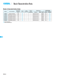
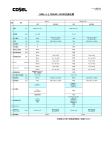
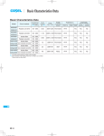
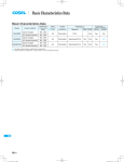
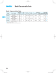
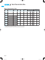
Basic Characteristics Data
PLA
Basic Characteristics Data
Rated
input fuse
Inrush
current
protection
circuit
Material
Single
sided
100
0.4 *1 250V 2.5A
Thermistor
CEM-3
Flyback converter
130
0.7 *1 250V 3.15A Thermistor
0.7 *1 250V 2.5A
Model
Circuit method
Switching
frequency
[kHz]
PLA15F
Flyback converter
PLA30F
PLA50F
PLA100F
PLA150F
PLA300F
PLA600F
*1
*2
*3
*4
Active filter
60 to 440
Flyback converter
130
Active filter
40 to 160
Flyback converter
20 to 150 *3
Active filter
40 to 160
Flyback converter
20 to 150 *3
Active filter
60
Forward converter
140
Active filter
60
Forward converter
220
Input
current
[A]
Series
operation
Parallel
operation
Yes
Yes
No
CEM-3
Yes
Yes
No
Thermistor
CEM-3
Yes
Yes
No
1.2 *2 250V 3.15A Thermistor
CEM-3
Yes
Yes
No
1.7 *2
250V 4A
Thermistor
CEM-3
Yes
Yes
No
3.4 *2
250V 10A
Thermistor
CEM-3
Yes
Yes
No
6.7 *2
250V 16A
SCR
FR-4
Yes
*4
The input current shown is at ACIN 100V and 100% load.
The input current shown is at ACIN 100V and 90% load.
The burst mode frequency varies according to the operating conditions. Consult us for more details.
Parallel operation is possible with the –W option. See “5. Options and Others” in Instruction Manual.
PLA-16
Series/Parallel
operation availability
PCB/Pattern
Double
sided
Yes
AC-DC Power Supplies Enclosed type Instruction Manual
PLA
1
2
3
Function
PLA-18
1.1
Input Voltage Range
PLA-18
1.2
Inrush Current Limiting
PLA-18
1.3
Overcurrent Protection
PLA-18
1.4
Overvoltage Protection
PLA-18
1.5
Thermal Protection
PLA-19
1.6
Output Ripple and Ripple Noise
PLA-19
1.7
Output Voltage Adjustment
PLA-19
1.8
Isolation
PLA-19
1.9
Low Power Consumption
PLA-19
1.10
Remote ON/OFF
PLA-19
1.11
Remote Sensing
PLA-19
1.12
LV Alarm
PLA-19
Series Operation and Parallel Operation
PLA-20
2.1
Series Operation
PLA-20
2.2
Parallel Operation
PLA-20
Assembling and Installation Method
PLA-20
3.1
Installation Method
PLA-20
3.2
Derating
PLA-21
3.3
Expected Life and Warranty
PLA-23
4
Ground
PLA-24
5
Options and Others
PLA-24
5.1
Outline of Options
PLA-24
5.2
Others
PLA-29
PLA-17
AC-DC Power Supplies Enclosed type
Instruction Manual
PLA
¿ PLA15F, PLA30F, PLA50F, PLA100F, PLA150F,
PLA300F
1 Function
¡Thermistor is used in the inrush current limiting circuit. When you
turn the power supply on and off repeatedly within a short period
1.1 Input Voltage Range
of time, have enough intervals for the power supply to cool down
¡The rated input voltage range of the power supply is AC85-264V
(See SPECIFICATIONS for more details).
¡To comply with the safety standards, use the power supply with
the input voltage range of AC100-240V (50/60Hz).
¡If the input voltage is outside the rated range, the power supply
may not operate in accordance with the specifications and/or start
hunting or fail.
before being turned on again.
¿ PLA600F
¡Thyristor technique is used in the inrush current limiting circuit.
When you turn the power supply on and off repeatedly within a
short period of time, have enough intervals for the inrush current
protection to become active.
¡If the input voltage changes suddenly, the output voltage may go
out of the specifications. Consult us for more details.
¡When the power supply is used with DC voltage input, an external
DC fuse is required for protection. Consult us for more details.
¡There will be primary inrush current and secondary inrush current
flowing because thyristor technique is used for the inrush current
limiting circuit.
1.3 Overcurrent Protection
¿ PLA15F, PLA30F
¡Power factor correction is not built-in. If multiple units are used in a
same system, the input harmonic current standard may not be met.
¡Overcurrent protection is built-in. It works at more than 105% of
the rated output current. The power supply recovers automatically
when the overcurrent condition is removed. Do not use the power
supply under a short-circuit or overcurrent condition.
Consult us more details.
¡Intermittent Operation Mode
When overcurrent protection works and the output voltage drops,
¿ PLA100F, PLA150F
¡If the input voltage is more than AC250V, power factor correction
does not work and the power factor deteriorates. Consult us for
the output voltage goes into intermittent mode so that the average
output current can decrease.
¡If the power supply is turned on with an overcurrent load, it will immediately go into intermittent mode and may not start up. See the
more details.
¿ PLA15F, PLA30F, PLA50F, PLA100F, PLA150F
¡The power supply is designed to handle instant voltage dip but output power derating is necessary.
characteristics below. ( PLA15F, 30F, 50F, 100F, and 150F)
Vo
100%
Not Intermittent
operation
-Use Conditions
Maximum output power
PLA15F
PLA30F
PLA50F
PLA100F
PLA150F
7.5W
10W
15W
40W
60W
Input AC50V (DC70V)
Duty 1s/30s
*Avoid using the power supply under the above-mentioned
conditions for more than 1 second continuously as the
power supply may be damaged.
¿ PLA300F, PLA600F
¡The –U option is available for PLA300F and PLA600F to handle
instant voltage dip of less than AC85V but output power derating
is necessary. (See 5. Options and Others.)
Intermittent operation
start voltage
Intermittent
operation
0%
Io
100 105min
Load factor [%]
Fig.1.1 Overcurrent protection characteristics
1.4 Overvoltage Protection
¡Overvoltage protection is built-in. If overvoltage protection works,
shut down the input voltage, wait more than 3 minutes, and turn
on the input voltage again to recover the output voltage. The recovery time varies depending on the input voltage, etc.
Remarks :
Avoid applying an overrated voltage to the output terminals as
it may cause the power supply to malfunction or fail. In case the
1.2 Inrush Current Limiting
above-mentioned situation is expected in operating such loads as
a motor, for example, consult us for advice.
¡Inrush current protection is built-in.
¡If you need to use a switch on the input side, select one that can
withstand an input inrush current.
PLA-18
AC-DC Power Supplies Enclosed type
Instruction Manual
PLA
1.5 Thermal Protection
¿ PLA300F, PLA600F
¿ PLA15F, PLA30F, PLA50F, PLA100F, PLA150F
¡With the option –V, the power supply comes with an external potentiometer instead of a built-in potentiometer. (See 5 Options and
¡These models are not equipped with thermal protection.
Others).
¿ PLA300F, PLA600F
1.8 Isolation
¡Thermal protection is built-in.
¡For a receiving inspection, such as Hi-Pot test, gradually increase
(decrease) the voltage for the start (shut down). Avoid using Hi-
Thermal protection will work under the following conditions and
the power supply will shut down.
Pot tester with the timer because it may generate voltage a few
1When the operating temperature and the output current greatly
exceed the derating curve.
times higher than the applied voltage, at ON/OFF of a timer.
2When the built-in cooling fan stops or the air flow from the fan is
obstructed.
If thermal protection works, switch off the input voltage and eliminate the conditions causing thermal protection to work. Allow
enough time for the unit to cool off before switching on the input
voltage again to recover the output voltage.
1.9 Low Power Consumption
¿ PLA15F, PLA100F, PLA150F
¡These power supplies are designed for low power consumption at no load. (No load power consumption: PLA15F:1.0W typ,
PLA100F/150F:1.5W typ)
¡When the load factor is 0 - 35% (PLA15F) and 0- 30% (PLA100F and
PLA150F), the switching power loss is reduced by burst operation,
1.6 Output Ripple and Ripple Noise
¡Output ripple noise may be influenced by the measuring environment. The measuring method shown in Fig. 1.2 is recommended.
+Vout
which will cause ripple and ripple noise to go beyond the specifications.
¡Ripple and ripple noise during burst operation will change depending
on the input voltage and the output current. Consult us for advice on
how to reduce ripple and ripple noise.
C1
C2 +
Load
-Vout
¡When there is a need to measure the stand-by power consumption,
measure it by using the average mode of the tester. The measuring
environment may influence the result. Consult us for more details.
150mm
Osiloscope/
Ripple noise meter
Bw:20MHz
1.10 Remote ON/OFF
Differential probe
C1 : Film capacitor 0.1μF
C2 : Aluminum electrolytic capacitor 22μF
Fig.1.2 Measuring method of Ripple and Ripple Noise
Remarks :
When measuring output ripple or ripple noise with an oscilloscope,
do not let the oscilloscope’s GND cable cross the magnetic flux
from the power supply. Otherwise there may be electrical potential
generated on the GND cable and the measuring result may not be
accurate.
¿ PLA15F, PLA30F, PLA50F
¡These models do not have the remote ON/OFF function.
¿ PLA100F, PLA150F, PLA300F, PLA600F
¡The –R option is available for these models. With the –R option,
remote ON/OFF is possible. See “5 Options and Others” for more
details.
1.11 Remote Sensing
¿ PLA15F, PLA30F, PLA50F, PLA100F, PLA150F,
PLA300F
¡These models do not have the remote sensing function.
¿ PLA600F
Bad example
Good example
Fig.1.3 Example of measuring output ripple and ripple noise
¡The –W option is available for PLA600F. With the –W option, remote sensing is possible. See “5 Options and Others” for more
details.
1.7 Output Voltage Adjustment
1.12 LV Alarm
¡The output voltage can be adjusted within the specified range by
turning the built-in potentiometer clockwise (up) or counterclock-
¿ PLA15F, PLA30F, PLA50F, PLA100F, PLA150F,
PLA300F
wise (down).
¡Please operate the potentiometer slowly.
¡These models do not have the LV alarm function.
PLA-19
Instruction Manual
AC-DC Power Supplies Enclosed type
PLA
¿ PLA600F
¡The –W option is available for PLA600F. With the –W option, the
power supply can give an LV alarm. See “5 Options and Others”
for more details.
3 Assembling and
Installation Method
3.1 Installation Method
2 Series Operation and
Parallel Operation
¡Do not insert a screw more than 6mm away from the outside of
a power supply to keep enough insulation distance between the
screw and internal components.
Chassis of
PLA
PBAseries
series
Chassis of
customer system
2.1 Series Operation
¡The power supplies can be used in series connection. The output
current in series operation must be lower than the rated current of
Mounting Screw
6mm max
the power supply with the lowest rated current among the power
supplies connected in series. Make sure no current exceeding the
Fig.3.1 Mounting screw
rated current flows into a power supply.
¿ PLA15F, PLA30F, PLA50F, PLA100F, PLA150F
Power +
Supply -
Terminal block
Load
Load
Load
Power +
Supply -
Power +
Supply -
Power +
Supply -
Terminal block
More than
20mm
Fig.2.1 Examples of connecting in series operation
(A)
2.2 Parallel Operation
Load
¡Redundant operation is possible by wiring as shown below.
I1
I3
Power +
Supply -
Power +
Supply -
(B)
(C)
¡If you use two or more power supplies side by side, please keep a
sufficient distance between them to allow enough air ventilation.
¡Ambient temperature around each power supply should not exceed the temperature range shown in the derating curve.
¿ PLA300F
I2
Terminal block
Fig.2.2 Example of redundancy operation
Vent hole
side More than
More than
30mm
30mm
More than
30mm
Terminal block
F Fan side
side
A
N
¡Even a slight difference in output voltage can affect the balance
between the values of I1 and I2.
Air flow
Terminal block
Make sure the value of I3 does not exceed the rated output cur-
(A)
rent of the power supply.
l3 [ the rated current value
¿ PLA15F, PLA30F, PLA50F, PLA100F, PLA150F,
PLA300F
Terminal block
Terminal block
More than
30mm
Vent hole
side
¡Parallel operation is not possible.
(B)
¿ PLA600F
¡The –W option is available for PLA600F. With the –W option, parallel operation is possible. See “5 Options and Others” for more
details.
PLA-20
(C)
Not allowed
(D)
Terminal block
(E)
AC-DC Power Supplies Enclosed type
Instruction Manual
PLA
¿ PLA600F
(1) Temperature at Point A ad Point B
More than
30mm
More than
Vent hole
30mm
side
More than
30mm
Terminal block
side
Terminal
block
F
A
N
Fan side
¡The operating temperature can also be designed by the case temperature with these models.
The temperatures in the tables show not the limit of use but the
Air flow
temperature of an expected life.
¡Make sure the case temperature at point A and point B is less than
the temperatures shown in Fig. 3.1 to Fig. 3.5.
Terminal block
(A)
Vent hole
side
Terminal block
Terminal block
side
More than
30mm
¿ PLA15F, PLA30F, PLA50F, PLA100F, PLA150F
¡When the power supply is used with a forced cooling, make sure the
case temperature requirements shown in Fig. 3.1 to Fig. 3.5 are met.
¡The expected life of the power supply at the highest allowed temperature at point A and point B is 3 years. See “3.3 Expected Life
and Warranty” to prolong the expected life.
See External View for the position of Point A and Point B.
(B)
(D)
(C)
Table 3.1 Temperature of Point A PLA15F-O
Not allowed
Terminal block
(E)
Mounting
Method
Load factor
Max temperature [C]
A, B, C
50%<Io[100%
Io[50%
78
85
¡Avoid installation method (E) as it gives excessive stress to the
mounting holes.
Table 3.2 Temperature of Point A PLA30F-O
¡Do not block air flow of the built-in fan (terminal block and ventilation hole).
Mounting
Method
¡If the power supply is used in a dusty environment, use an airfilter. Make sure air flow is not blocked.
A
¡If the built-in fan stops, thermal protection will work and the output
will stop. Periodic maintenance of the built-in fan is necessary to
B, C
Load factor
Max temperature [C]
50%<Io[100%
Io[50%
50%<Io[100%
Io[50%
80
88
72
82
enhance the power supply’s reliability.
¡The expected life (R(t)=90%) of the built-in fan varies depending
Table 3.3 Temperature of Point A PLA50F-O
Mounting
Method
on the operating condition.
3.2 Derating
A
¡Input Voltage Derating Curve
The input voltage derating curve is shown in Fig. 3.2.
Max temperature [C]
50%<Io[100%
Io[50%
50%<Io[100%
Io[50%
78
81
66
71
Table 3.4 Temperature of Point A PLA100F-O
[%]
100
Load
B, C
Load factor
Mounting
Method
A, B, C
90
Load factor
Max temperature [C]
Io[100%
81
80
Table 3.5 Temperature of Point A, Point B PLA150F-O
85 100 115
[AC V]
Fig.3.2 Input voltage derating curve
Mounting
Method
Load factor
A, B, C
Io[100%
Max temperature [C]
Point A
Point B
85
78
¡Ambient Temperature Derating Curve
The derating curves by the ambient temperature are shown in Fig.
3.3 to Fig. 3.10.
*The specifications of ripple and ripple noise change in the shaded
area.
PLA-21
Instruction Manual
AC-DC Power Supplies Enclosed type
PLA
¿ PLA100F, PLA150F
(2) Derating Curves by Ambient Temperature
¡The derating curve by the ambient temperature shows the operating temperature range for a 3-year continuous use. It shows not the
Load factor [%]
limit of use but the temperature of an expected life.
Consult us for the operation limit temperature.
¿ PLA15F
100
Load factor [%]
2
1
100
1Convection (A mount)
2Convection (B, C mount)
3Forced air (0.5m3 / min)
50
40
35
0
10
20
30
40
50
60
70
80
100
Load factor [%]
2
1
Load factor [%]
-10
¿ PLA30F
3
-10
0
10
50 55 60
70
80
60
3
1
1Convection (A mount)
2Convection (B, C mount)
3Forced air (0.5m3 / min)
50
40
30
20
-10
0
10
20
30 35 40 45 50 55 60
70
80
Fig.3.8 Ambient temperature derating curve for PLA100F/150F-24, -36, -48
50
1Convection (A mount)
2Convection (B, C mount)
3Forced air (0.5m3 / min)
40
-10
0
10
20
30
40
¿ PLA15F, PLA30F, PLA50F, PLA100F, PLA150F
50
60
70
80
¡The ambient temperature should be measured 5 to 10 cm away
from the power supply so that it won’t be influenced by the heat
from the power supply. Please consult us for more details.
Ambient temperature [C]
Fig.3.4 Ambient temperature derating curve for PLA30F
¿ PLA300F
¿ PLA50F
100
80
80
2
Load factor [%]
100
3
1
60
50
1Convection (A mount)
2Convection (B, C mount)
3Forced air (0.5m3 / min)
40
20
60
50
40
20
0
-20
-10
0
10
20
30
40
50
60
70
80
Ambient temperature [C]
-10
0
10
20
30 35 40
50
60
70
80
Fig.3.9 Ambient temperature derating curve for PLA300F
Ambient temperature [C]
Fig.3.5 Ambient temperature derating curve for PLA50F-5
¿ PLA600F
100
100
2
1
80
3
Load factor [%]
80
60
50
1Convection (A mount)
2Convection (B, C mount)
3Forced air (0.5m3 / min)
40
20
10
0
-20
40
Ambient temperature [C]
60
10
0
-20
30
2
70
0
-20
20
80
0
-20
80
20
Load factor [%]
30
100
Fig.3.3 Ambient temperature derating curve for PLA15F
Load factor [%]
40
Fig.3.7 Ambient temperature derating curve for PLA100F/150F-12, -15
Ambient temperature [C]
-10
0
10
20
30 35 40 45 50 55 60
60
40
20
70
80
Ambient temperature [C]
Fig.3.6 Ambient temperature derating curve for PLA50F-12, -15, -24
PLA-22
50
Ambient temperature [C]
20
0
-20
1Convection (A mount)
2Convection (B, C mount)
3Forced air (0.5m3 / min)
60
0
-20
60
3
1
20
3
80
70
2
80
0
-20
-10
0
10
20
30
40
50
60
70
80
Ambient temperature [C]
Fig.3.10 Ambient temperature derating curve for PLA600F
AC-DC Power Supplies Enclosed type
Instruction Manual
PLA
¿ PLA300F, PLA600F
¿ PLA300F, PLA600F
¡The ambient temperature is defined as the temperature of the air
(at the terminal block side) that the built-in cooling fan blows into
the power supply. Please pay attention to the heat generated by
Table 3.10 Expected lifetime (PLA300F/PLA600F)
Mounting
Average ambient
Cooling method
temperature
the input and output wires. Please consult us for more details.
Ta = 30C
Ta = 40C
Ta = 50C
Forced air cooling
All
direction
(internal fan)
3.3 Expected Life and Warranty
¡Expected Life
The expected life of the power supply is shown below.
¿ PLA15F, PLA30F
Expected lifetime
[years]
Io[50% Io[100%
10
7
7
5
5
3
*This lifetime includes a built-in fan lifetime.
¡The built-in cooling fan should be changed periodically. The expected life time (R (t) = 90%) of the built-in fan depends on the
operating condition as shown in Fig. 3.11.
Table 3.6 Expected lifetime (PLA15F, PLA30F)
Cooling
Average ambient
Method
Method
temperature
A
Convection
B, C
Convection
A, B, C
Forced air cooling
Ta = 40C
Ta = 50C
Ta = 30C
Ta = 40C
Ta = 50C
Ta = 60C
Expected lifetime
[years]
Io[50% Io[100%
7
5
5
3
7
5
5
3
5
5
5
3
¿ PLA50F
Table 3.7 Expected lifetime (PLA50F-5)
Mounting
Cooling
Average ambient
Method
Method
temperature
A, B, C
Convection
A, B, C
Forced air cooling
Ta = 25C
Ta = 35C
Ta = 40C
Ta = 50C
500,000
Expected Lifetime [H]
Mounting
100,000
10,000
Expected lifetime
[years]
Io[50% Io[100%
7
5
5
3
7
5
7
3
20
Cooling
Average ambient
Method
Method
temperature
A
Convection
B, C
Convection
A, B, C
Forced air cooling
Ta = 35C
Ta = 45C
Ta = 25C
Ta = 35C
Ta = 45C
Ta = 55C
Expected lifetime
[years]
Io[50% Io[100%
7
5
5
3
7
5
5
3
7
5
7
3
40
50
60
70
80
Temperature of measurement point [C]
Fig.3.11 Expected lifetime of fan
AIR FLOW
Table 3.8 Expected lifetime (PLA50F-12, -15, -24)
Mounting
30
Terminal
block
Power supply
(Top)
F
A
N
Measurement point
20mm
AIR FLOW
Terminal
block
Power supply
(Side)
F
A
N
Measurement point
20mm
¿ PLA100F, PLA150F
Fig.3.12 Temperature of measurment point for fan lifetime
Table 3.9 Expected lifetime (PLA100F/PLA150F)
Mounting
Cooling
Average ambient
Method
Method
temperature
A
Convection
B, C
Convection
A, B , C
Forced air cooling
Ta = 30C
Ta = 40C
Ta = 20C
Ta = 30C
Ta = 40C
Ta = 55C
Expected lifetime
[years]
Io[50% Io[100%
10
5
5
3
10
5
5
3
10
5
5
3
PLA-23
AC-DC Power Supplies Enclosed type
Instruction Manual
PLA
¡Warranty
The maximum warranty period is 5 years as shown in Fig. 3.11 to
Fig. 3.15.
¿ PLA15F, PLA30F
Table 3.11 Warranty (PLA15F/PLA30F)
Mounting
Cooling method
A
Convection
B, C
Convection
A, B, C
Forced air cooling
Average ambient
temperature
Ta = 40C
Ta = 50C
Ta = 30C
Ta = 40C
Ta = 50C
Ta = 60C
Warranty [years]
Io[50% Io[100%
5
5
5
3
5
5
5
3
5
5
5
3
¿ PLA50F
Table 3.12 Warranty (PLA50F-5)
Mounting
Cooling method
A, B, C
Convection
A, B, C
Forced air cooling
Average ambient
temperature
Ta = 25C
Ta = 35C
Ta = 40C
Ta = 50C
Warranty [years]
Io[50% Io[100%
5
5
5
3
5
5
5
3
Table 3.13 Warranty (PLA50F-12, -15, -24)
Mounting
Cooling method
A
Convection
B, C
Convection
A, B, C
Forced air cooling
Average ambient
temperature
Ta = 35C
Ta = 45C
Ta = 25C
Ta = 35C
Ta = 45C
Ta = 55C
Warranty [years]
Io[50% Io[100%
5
5
5
3
5
5
5
3
5
5
5
3
¿ PLA100F, PLA150F
Mounting
Cooling method
A
Convection
B, C
Convection
A, B, C
Forced air cooling
temperature
Ta = 30C
Ta = 40C
Ta = 20C
Ta = 30C
Ta = 40C
Ta = 55C
¡When installing the power supply, make sure the FG terminal and
the chassis (at more than 2 places) are connected to the safety
earth ground.
5 Options and Others
5.1 Outline of Options
¿ –C (PLA15F, PLA30F, PLA50F, PLA100F,
PLA150F, PLA300F, PLA600F)
-With the –C option, the internal PCB has a conformal coating for
anti-humidity.
¿ –G (PLA300F, PLA600F)
-With the –G option, the leakage current of the power supply is
reduced.
-The differences between the option –G models and the standard
models are shown below.
Table 5.1 Low leakage current type
Leakage Current
(AC240V 60Hz)
Conducted Noise
Output Ripple Noise
0.15mA max
N/A
Please contact us for details about
Ripple Noise
* This is the result of measurement of the testing board with capacitors of 22μF and 0.1μF placed at 150 mm from the output terminals by a 20 MHz oscilloscope or a ripple-noise meter equivalent
Table 3.14 Warranty (PLA100F/PLA150F)
Average ambient
4 Ground
Warranty [years]
Io[50% Io[100%
5
5
5
3
5
5
5
3
5
5
5
3
¿ PLA300F, PLA600F
to Keisoku-Giken RM103.
¿ –V (PLA300F, PLA600F)
-With the –V option, the power supply comes with an external
potentiometer connector instead of a built-in potentiometer.
-The appearance of the –V models is different from that of the
standard models. Contact us for more details.
-Note that if the power supply is turned on with CN3 open, the
output voltage will make a big drop.
Table 3.15 Warranty (PLA300F/PLA600F)
Mounting
Cooling method
Forced air cooling
All
direction
(internal fan)
Average ambient
temperature
Ta = 40C
Ta = 50C
Warranty [years]
Io[50% Io[100%
5
5
5
3
+V
+V
CN3
V.ADJ
PLA-24
Fig.5.1 Front view of option-V (PLA600F)
Instruction Manual
AC-DC Power Supplies Enclosed type
PLA
¿ –U (PLA300F, PLA600F)
-With the –U option, the power supply can handle an instantaneous input voltage dip (output power derating is required).
-Operating condition (as per SEMI F-47)
¡Remote on/off control for PLA100F, PLA150F, and PLA300F
-Remote control connectors are added. Contact us for more details.
-Make sure there is an interval of more than 2 seconds in the on/
off cycle. If the interval is shorter, the start-up time may become
longer (approx. 2 seconds).
Maximum output power *( ) is 5V output model.
PLA300F
PLA600F
120W (100W)
240W (200W)
Input AC50V
Duty 1s/30s
*Do not continue the above-mentioned operating conditions for
more than 1 second. Otherwise the power supply may be damaged.
¿ –R (PLA100F, PLA150F, PLA300F, PLA600F)
-The –R option makes it possible to switch on or off the output by
applying voltage to the RC terminals of the power supply from
an external power source.
Fig.5.3 Example of option -R (PLA100F, PLA150F)
-The appearance of the option –R models is different from that of
the standard models.
-Designated harnesses for the RC terminals are available for
sale. See Optional Parts for more details.
-The –R option models have extra connectors. Please contact us
for more details.
Table 5.3 Pin configuration and function of CN4
PIN
1
2
Connector
Voltage between RC
Built-in
Input
and RCG [V]
Resistor
Current
Ri [ W ] Output ON Output OFF [mA]
PLA100F, PLA150F,
PLA300F, PLA600F
780
0 - 0.5
SW
Inside of a Power
Supply
RC
B2B-XH-AM
Terminal
BXH-001T-P0.6
Mfr
or
J.S.T.
XHP-2
SXH-001T-P0.6
CN1
(20max)
V.ADJ
4.5 - 12.5
CN4
Housing
CN1
R*1
FUNCTION
RC :Remote ON/OFF
RCG:Remote ON/OFF (GND)
Table 5.4 Mating connectors and terminals on CN4
Table 5.2 Remote on/off operating conditions
Model Name
RCG 2
RC 1
CN4
Ri
1 RC
2 RCG
+V
+V
Input Current
-V
External Power
Source
-V
RCG
FG
(G)
AC
(N)
Remote ON/OFF connector (Optional)
AC
(L)
Fig.5.2 Example of using a remote ON/OFF circuit
*1 If the external voltage applied to the –RC terminals is 4.5
-12.5V, the current limiting resistor is not necessary. If the volt-
Fig.5.4 Example of option -R (PLA300F)
age applied is more than 12.5V, make sure the current limiting
Table 5.5 Pin configuration and function of CN1
resistor R is used.
The value of the current limiting resistor is obtained by the following formula:
R[W]=
Vcc-(1.1+RiX0.005)
0.005
PIN
1
2
Vcc : External Power Source
*Note that reversed connection damages internal components of
the power supply.
FUNCTION
RC :Remote ON/OFF
RCG:Remote ON/OFF (GND)
Table 5.6 Mating connectors and terminals on CN1
Connector
CN1
XARR-02V
Housing
Terminal
Mfr
XAP-02V-1
SXA-001T-P0.6
J.S.T.
*The remote control circuit is isolated from input, output and FG.
PLA-25
Instruction Manual
AC-DC Power Supplies Enclosed type
PLA
¡Remote on/off control for PLA600F
-The appearance of the –R option model is different from that of
Table 5.10 Pin configuration and function of CN1 and CN2
PIN
CN1
V.ADJ
1
9
Table 5.7
PIN
1
2
3
4
5
6
7
8
9
10
Pin configuration and function of CN1
FUNCTION
:N.C.
:N.C.
RC :Remote ON/OFF
RCG:Remote ON/OFF(GND)
:N.C.
:N.C.
:N.C.
:N.C.
:N.C.
:N.C.
1
9
9
10
Fig.5.5 Front view of option -R (PLA600F)
2
9
AC AC
(N) (L)
CN 2
FG
CN1
2
3
4
5
6
7
8
-V
1
-V
10
+V
2
+V
10
1
CN 1
2
the standard model as CN1 is added. Contact us for more details.
10
Fig.5.8 Pin number
FUNCTION
+M :Self sensing terminal (Don’t
+S
LV
LVG
CB
-M
wire for external function)
:+Sensing
:N.C.
:N.C.
:LV alarm
:LV alarm (GND)
:Current balance
:N.C.
:Self sensing terminal (Don’t
-S
wire for external function)
:-Sensing
Table 5.11 Mating connectors and terminals on CN1 and CN2
Connector
CN1
CN2
Housing
Terminal
Reel :SPHD-002T-P0.5
S10B-PHDSS PHDR-10VS Loose :BPHD-001T-P0.5
Mfr
J.S.T.
:BPHD-002T-P0.5
¡LV alarm
The operating conditions of the LV alarm are shown in Table 5.12.
The internal circuit of the LV alarm is shown in Fig. 5.9. The LV
alarm is isolated from input, output, and FG.
Fig.5.6 Pin number
0. 1 F
Table 5.8 Mating connectors and terminals on CN1
Connector
Housing
Terminal
Reel :SPHD-002T-P0.5
100 kW
LV
Mfr
Current limiting
resistor
CN1 S10B-PHDSS PHDR-10VS Loose :BPHD-001T-P0.5 J.S.T.
External power
source
:BPHD-002T-P0.5
LVG
¿ –W (PLA600F only)
Fig.5.9 LV internal circuit
-The –W option model provides remote sensing, low output voltage alarm (LV alarm), and parallel operation.
Table 5.12 LV alarm operating conditions
-The appearance of the –W option model is different from that of
the standard mode. Contact us for more details.
Alarm
If the output voltage drops or
Output of alarm
Open collector method
-Designated harnesses are available for sale. See Optional
Parts.
stops, the LV and LVG terminals
Good : Low
-The differences from the standard model are shown in Fig. 5.9.
Note : 1In case of overcurrent,
the alarm signal will be
Table 5.9 Specification differences of Option -W
give an alarm signal.
LV
(0 - 0.8V, 10mA max)
Fail
: High or Open
50V
10mA max
unstable.
Load regulation
1.5 times of standard spec.
Ripple
1.5 times of standard spec.
2The alarm signal won’t
be given in parallel
Ripple noise
1.5 times of standard spec.
operation if OR diodes
are not used.
CN1
H-SN-31
(install)
¡Parallel operation
For parallel operation, please take the following steps:
+V
+V
-V
-V
FG
AC AC
(N) (L)
CN2
1 (Before wiring) set the output voltage of each unit to the desired
value. The output voltage difference between the units must be
less than 0.1V or 1% of the rated output voltage, whichever is
smaller.
Fig.5.7 Front view of option -W
2 Wire the power supplies as shown in Fig. 5.10. Make sure the
output wires of the units connected in parallel are of the same
length and the same type.
PLA-26
Instruction Manual
AC-DC Power Supplies Enclosed type
PLA
3 Make sure the total output current does not exceed the value
determined by the following formula:
Output current in
parallel operation
=
The rated
current per unit
X (Number of unit) X0.85
*Make sure the current drawn from each unit is less than the
rated output current.
-When adjusting the output voltage after wiring, repeat the abovementioned steps (1 to 4).
-If the number of units in parallel increases, the input current increases as well. Make sure the input equipment and wires have
enough current capacity.
-The maximum number of units for parallel connection is 5.
-Master-Booster operation is not possible.
2 Make sure the wires between the load and the power supply are
thick enough to keep the line drop less than 0.3V.
3 If the sensing wires are long, place C1 and R1 across the load
lines.
4 Use a twisted pair wire or a shielded wire for the sensing lines.
5 Do not draw the output current from +M, –M, +S or –S.
6 The impedance of the wiring or the load may cause the output
voltage to oscillate or fluctuate.
Test to confirm remote sensing works fine. If the output voltage is
found to be unstable, the following methods are recommended:
- Remove the remote sensing line on the minus side and short
–S and –M.
- Use C1, R1, and R2.
CN1
CB
-S
CB
-S
Short at CN1
(H-SN-31)
+M
+S
-S
-M
CB
-S
+V
C1
Load
-V
Fig.5.11 When not using remote sensing function
(+)
Wire the sensing lines as close
as possible
(-)
Load
Fig.5.10 Parallel operation condition
CN1
+M
+S
-S
-M
R1
+V
-If the output current is less than 10% of the rated output current,
the output voltage may fluctuate.
Load
-V
R2
C1
The required minimum current is different depending on the model
and the number of units in parallel. Consult us for more details.
-If the length of the output wires of each unit is different, the output
current from each unit will be unbalanced. Make sure to use output wires of the same length for all units in parallel.
¡Remote sensing
-These models are equipped with a remote sensing function.
If the remote sensing is not used, the following terminals of CN1
Fig.5.12 When using remote sensing function
¿ –T (PLA15F, PLA30F, PLA50F, PLA100F,
PLA150F)
-The –T option models come with a vertical terminal block.
The appearance is different from that of the standard models.
Contact us for more details.
must be shorted:
M3.5
+S and +M
AC(L)
–S and –M
AC(N)
When the power supply is shipped from our factory, a designated
FG( )
Output
terminal(-)
Output
terminal(+)
harness (H-SN-31) is attached to CN1. If remote sensing is not
used, there is no need to remove the harness.
-The wire connection when remote sensing is used or not used is
shown in Fig. 5.11 - Fig. 5.12.
V.ADJ
-When using remote sensing, make sure to finish wiring +S and
–S first. The designated harness is available for sale. Contact us
for more details.
-When using remote sensing, pay attention to the following:
1 Wiring must be done carefully. If there is bad connection on the
Fig.5.13 Example of option -T(PLA100F)
load lines due to loose screws, etc., the load current flows into
the sensing lines and the internal circuit of the power supply may
be damaged.
PLA-27
AC-DC Power Supplies Enclosed type
Instruction Manual
PLA
¿ –T2 (PLA300F, PLA600F)
Table 5.14 Mating connectors and terminals on CN1 and CN2 in option -J
(PLA100F, PLA150F)
-The –T2 option models come with a normal (non-screw-hold
type) terminal block. The appearance is different from that of the
standard models. Contact us for more details.
M4
+V
Output
terminal (-)
+V
V.ADJ
Output
terminal (+)
I/O Connector
Matching Housing
CN1 1-1123724-3
1-1123722-5
CN2 1-1123723-6
1-1123722-6
Reel
Loose
Reel
Loose
Terminal
: 1123721-1
: 1318912-1
: 1123721-1
: 1318912-1
(Mfr. Tyco electronics AMP)
¿ –L (PLA100F, PLA150F)
-V
-V
-With the –L option models, power consumption at no load is
smaller than that of the standard models.
FG
AC
(N)
AC
(L)
FG( )
AC(N)
AC(L)
[Power consumption at no load]
Option -L
: 0.5W max
Standard model (Reference) : 1.5W typ
Condition: AC240V input, Io=0A
Fig.5.14 Example of option -T2(PLA300F)
¿ –J (PLA15F, PLA30F, PLA50F, PLA100F,
PLA150F)
-The –J option models come with AMP connectors instead of a
terminal block.
-The designated harnesses are available for sale. See Optional
Parts for more details.
-The appearance is different from that of the standard models.
Contact us for more details.
-Keep the drawing current less than 5A per pin.
-UL508 does not apply to the –J option models.
-When the ambient temperature is from -10C to -20C, use the
power supply with the input voltage range of AC115-264V.
-Make sure to have 1-second interval from turning off to turning
on again. If the interval is shorter, the output voltage may hunt.
-The dynamic load response (Io=0%-100%) is different from
that of the standard models. Test to confirm the actual voltage
change in the final application before using.
¿ –F4 (PLA300F, PLA600F)
-The –F4 option models come with a low-speed fan to reduce the
fan noise.
-The differences from the standard fan versions are shown in
Fig. 5.16 and Fig. 5.17.
100
CN1
80
Load factor [%]
AC(L)
AC(N)
FG
-V
CN2
60
50
40
20
+V
V.ADJ
0
-20
-10
0
10
20
30
40
50
60
70
Ambient temperature [C]
Fig.5.16 Ambient temperature derating curve for PLA300F (Option-F4)
Fig.5.15 Example of option -J (PLA100F)
100
2
Table 5.13 Mating connectors and terminals on CN1 and CN2 in option -J
(PLA15F, PLA30F, PLA50F)
I/O Connector
Matching Housing
CN1 1-1123724-3
1-1123722-5
CN2 1-1123723-4
1-1123722-4
(Mfr. Tyco electronics AMP)
Terminal
Reel : 1123721-1
Loose : 1318912-1
Reel : 1123721-1
Loose : 1318912-1
Load factor [%]
80
1
60
1PLA600F-5-F4
2PLA600F-12,15,24,36,48-F4
50
40
20
0
-20
-10
0
10
20
30
40
50
60
70
Ambient temperature [C]
Fig.5.17 Ambient temperature derating curve for PLA600F (Option-F4)
PLA-28
AC-DC Power Supplies Enclosed type
Instruction Manual
PLA
¿ –N1 (PLA15F, PLA30F, PLA50F, PLA100F,
PLA150F)
-The –N1 option models come with a DIN rail mount attachment.
-The appearance is different from that of the standard models.
Contact us for more details.
-The –N1 option models have different vibration and shock specifications. Consult us for more details.
-Contact us for safety agency approvals.
Fig.5.18 Power supply installed on a DIN rail (PLA100F)
5.2 Others
¡Note that the case of the power supply remains hot for a while after it is turned off.
¡If large capacitors are connected to the output terminals (load
side), the output voltage may stop or become unstable. Consult us
for advice.
¡If the power supply is turned off at no load, the output voltage remains for a few minutes as the power supply is designed for low
internal power consumption. Be careful of electrical shock at the
time of maintenance.
¡If the built-in cooling fan in PLA300F/PLA600F stops, the built-in
thermal protection may work and the output voltage may stop. Periodic maintenance of the built-in fan is necessary to enhance the
power supply’s reliability.
¡When more than two units are connected in parallel at the input,
the total capacitance between the lines becomes larger and a
discharge resistance may be necessary to meet the safety agency
approvals. Consult us for advice.
PLA-29