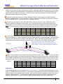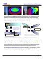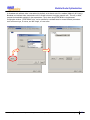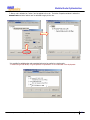
1
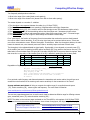
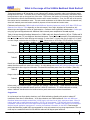
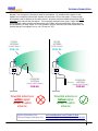
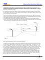
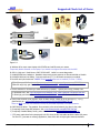
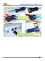
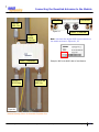
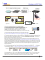
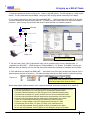
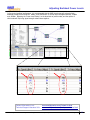
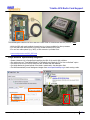
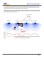
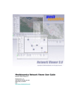
MD4000 Node Deployment
and
Trouble Shooting Guide
Wireless for the Outdoor EnterpriseTM
HWIG D07 © 2005-2007 Meshdynamics. All Rights Reserved. Proprietary Information. Patented and Patents Pending
1
The MD 4000 Product Family
The MD4000 Modular MeshTM products support up to 4 radios in a single enclosure. All
Meshdynamics radios use a two radio backhaul that differs significantly from competing mesh products The
differences are explained at: www.meshdynamics.com/third_generation.html
Slots 0, 1 house one uplink backhaul and one downlink backhaul radio operating on non-interfering
channels but in the same frequency band. Slot 2 can house a third radio for client (laptops etc) connectivity.
This is generally a 2.4G AP radio. It can be set to 802.11b, b and g, or g only modes. Slot 3 can house a 2nd
downlink, a 2nd AP, or a scanning radio for a mobile mesh module - that forms part of the meshed backhaul in
dynamic infrastructure/high speed mobile mesh networks.
There are two Ethernet ports on each module that are used to interface with devices such as IP based cameras
for high resolution video over mesh. A 2nd (slave) module can attach via Ethernet to provide a total of 8 radios.
Operating temperature range is -40 to +85 Celsius. The die cast weather proof enclosure is NEMA 67 rated.
2.4GHz Backhaul Products (Standard Configurations)
3
0
MD4220
1.
2.
3.
4.
Uplink
Downlink
Service
Scanner
MD4424
1
2
2.4G 5.8G
3
0
MD4325
1
2
3
0
MD4320
1
2
3
0
1
2
MD4220-IIxx: 2-Radio module 2.4GHz uplink and downlink Backhaul (BH).
MD4320-IIIx: 3-Radio module 2.4GHz sectored BH slots 0,1 and 2.4GHz AP radio in slot 2.
MD4325-IIxI: 3-Radio module 2.4GHz BH, Downlink also acts as AP. A 2.4GHz Mobility Scanner in slot 3.
MD4424-IIII: 4-Radio module 2.4GHz service radios (AP) in all slots. Use with 4 panel antennas
5GHz Backhaul Products (Standard Configurations)
3
0
MD4250
2
1.
2.
3.
4.
5.
6.
3
0
MD4350
1
2
3
0
MD4452
1
2
3
0
MD4454
1
2
3
0
MD4455
MD4458
1
2
3
0
1
2
1
MD4250-AAxx: 2-Radio module 5GHz uplink and downlink Backhaul (BH).
MD4350-AAIx: 3-Radio module 5GHz BH and 2.4GHz AP radio in slot 2. AP modes may be b, g, or b & g.
MD4452-AAIA: 4-Radio module 5GHz BH and 2.4GHz AP radio. Second sectored 5.8GHz downlink in slot 3.
MD4454-AAAA: 4-Radio module 5GHz with radios as downlinks. Intended as root with four 90 deg panels.
MD4458-AAII: 4-Radio module 5GHz BH and two 2.4GHz AP radios in slots 2, 3 for sectored service.
MD4455-AAIA: 4-Radio module 5GHz BH and 2.4GHz AP radio in slot 2. 5GHz mobility scanner in slot 3.
Notes:
1.
2.
3.
4.
5.
6.
7.
8.
All 2.4G Downlinks and APs may be configured to support b only, g only, or b & g client connectivity.
All 5.8G Downlinks may be configured to provide 802.11a client connectivity.
All radio interfaces support IEEE 802.11e differentiated Class of Service.
All radio interfaces support VLAN, Multiple SSIDs, Hidden SSIDs etc.
Backhaul traffic is always encrypted. Client AP radio traffic may or may not be, based on user settings.
4.9G radios may be substituted for either backhaul radios or client AP radios. Contact Tech support for details.
GPS radio integration on the board serial line is supported as an option on all models. See page 14.
Intrinsic safe versions of all MD4000 products available. Contact us for details.
HWIG D07 © 2005-2007 Meshdynamics. All Rights Reserved. Proprietary Information. Patented and Patents Pending
2
Terminology
Wireless
RELAY 2
Backhaul
RELAY 1
Ethernet
Fig. 3.1
Root and Relay Nodes
Mesh Networks provide long range connectivity by relaying packets from one mesh node to another, like a bucket
brigade. The end of the bucket brigade terminates at the root – which connects to the Ethernet(above). Relays
connect to the root or other relay nodes to form a wirelessly linked chain.
Upstream & Downstream
Upstream implies closer to the Ethernet. The root is upstream of relay 1.
Wireless Uplinks and Downlinks. The Ethernet link is the uplink
(upstream link) connection for the root. The root has is a wired
uplink. Its “backhaul” is the wired network.
Ethernet
ROOT
DOWNLINK
Relays have wireless uplinks to an upstream downlink radio.
Downlink radios act like Access Points (AP) : they send out a beacon.
Uplink radios act like clients – they do not send out a beacon.
A wireless radio card in a laptop can inform you of the presence of
downlinks but not of uplinks. Downlinks beacon, Uplinks do not.
The uplink and downlink radios form a wireless backhaul path.
UPLINK
SERVICE
RELAY
AP radios operate in the 2.4GHz band to service 802.11b/g clients.
802.11a wireless devices may be serviced by the 5.8GHz downlink.
Thus, both 802.11a and 802.11b/g client access is supported.
Backhaul radios operate in 5.8GHz band to avoid interference with the
802.11b/g 2.4GHz AP radio (shown in pink, right).
Fig. 3.2
To summarize, there are 4 types of “links” to Structured MeshTM products:
A wired uplink to provide Ethernet connectivity. This connects the root node to the wired network.
A wireless downlink to provide wireless connectivity for uplinks of other nodes. These are typically 5.8GHz.
A wireless uplink to connect to the downlinks of upstream mesh nodes. These are typically 5.8GHz.
An AP radio for clients. Typically 2.4GHz with support for both b and g clients and 2.4GHz uplinks.
In our standard offering Model MD4350 the 802.11a uplink, the 802.11a downlink and 802.11b/g service
are 3 separate radios – see Fig. 3.2.
HWIG D07 © 2005-2007 Meshdynamics. All Rights Reserved. Proprietary Information. Patented and Patents Pending
3
Computing Effective Range
Two frequently asked questions asked are:
1. What is the range of the nodes (Node to node spacing)
2. What is the range of the Access Point (Access Point radio to client radio spacing).
The answer depends on a number of variables:
1.
2.
3.
4.
5.
6.
The
The
The
The
The
The
throughput rate requested between the radios (e.g. 12 Mbps TCP/IP)
frequency at which the radios are operating. Range decreases with higher frequencies.
receive sensitivity (RS) of the receiver radio for that throughput rate. (RS decreases at higher values).
transmit power (TP) of the transmitting radio at that throughput rate - decreases at higher values.
antenna gains on receiver and transmitting radios. Higher gains mean bigger “ears” – increased range..
environment – clear line of sight or dense foliage etc. Occlusions reduce range.
For a “good signal”, the fraction of the energy from the transmitter that reaches the receiver should exceed
the receiver radio’s receive sensitivity. If not, the noisy signal may not be received without errors. If there are
errors then re-transmission occurs. Effective throughput thus declines. When the throughput declines, the radio
lowers the transmit rate, since transmit power and receive sensitivity improve at lower transmit rates.
The throughput is thus adjusted based on signal quality. Signal quality in turn depends on transmit power (TP)
of the sender (how loud it is speaking) and RS receiver sensitivity (RS) (how sensitive the listener ears are). The
table below is from the data sheet of a typical 802.11a radio. Both RS and TP improve at lower throughput. Note
that since this is a log scale, a 6 db increase (from 20 to 26) is effectively quadrupling the transmit power.
Case
01
02
03
04
Freq (MHZ) Raw Throughput (Mbps)
5800
5800
5800
5800
TCP/IP Throughput
RS (dBm)
TP(dBm)
22
19
14
10
-74
-76
-85
-90
20
22
25
26
54
48
36
24
Degradation of signal quality over distance is expressed by the free space path loss relationship:
Path_Loss = 20*log(Freq) + Decay_* 10*log(Dist) – K where
Path_loss: Path Loss in dBm
Freq: Frequency in MHZ
Decay : Varies based on RF environment, line of sight etc.
Dist: Distance between the two mesh nodes (in meters)
K: Constant.
For a particular radio frequency and distance between the transmitter and receiver radios, the path loss must
exceed the noise threshold of the receiving radio receive sensitivity for the transmission to be “heard”.
A range estimate work sheet will help you compute the usable range, for a supplied transmit power
(TP), receive sensitivity (RS), antenna gains and frequency. The work sheet is located at:
www.meshdynamics.com/documents/MDrangecalculations.xls
The next two pages demonstrate how to use this work sheet to determine effective range for differing antenna
gains, transmitter power (TP) and and receiver sensitivity (RS) .
NOTE: The tables on the next two pages are based on the TP and RS for a throughput of 18-22 Mbps TCP/IP.
These are the most conservative range estimates, since at lower throughputs, the range is significantly higher.
Contact Information Link:
Technical Support Literature Link:
www.meshdynamics.com/Contact-Us.html
www.meshdynamics.com/tech-presentations.html
HWIG D07 © 2005-2007 Meshdynamics. All Rights Reserved. Proprietary Information. Patented and Patents Pending
4
What is the range of the 5.8GHz Backhaul Mesh Radios?
Throughput between an RF transmitter on one node and a RF receiver on another node is not unlike two people
talking across the room. The talker has to be loud enough to be heard above the noise and/or the listener has to
have good ears to pick up the signal out of the noise. In RF terms, the fraction of the energy from the transmitter
that reaches the receiver should exceed the receiver radio’s receive sensitivity. If not, the ACK will not be sent by
the receiver and re-transmissions occur. The rate control mechanism on the radios then lowers the transmit rate,
since both transmit power and receive sensitivity improve at lower transmit and receive rates.
Field tests confirm that the 5.8GHz backhaul with 8dB omni directional antennas provide 18-22 Mbps TCP/IP over
distances from 400m to 750m depending on the environment, line of sight, alignment of the antennas, etc.
Antenna type and alignment are key to good reception. Customers have successfully placed nodes 14 miles apart
using high gain well aligned antennas. Additional radio transmit power amplification was not required.
Table A1 shows theoretical backhaul distances for a 5.8GHz radio with Receive Sensitivity (RS) at –75 dBm and 20
dBm Transmit Power (TP) over 8dB omni directional antennas. “Decay” reflects the amount of transmitted energy
that reaches the receiver under differing environments. It varies from 2.1 (rural, clear line of sight) to 2.4 (urban,
non line of sight, occlusions due to foliage etc.). NOTE: Values relate to 18-22 Mbps TCP/IP backhaul throughput.
Case
Table A1
01
02
03
04
RS (dBm)
TP(dBm)
Decay
Antenna 1
Antenna 2
Freq (MHZ)
-75
-75
-75
-75
20
20
20
20
2.1
2.2
2.3
2.4
8
8
8
8
8
8
8
8
5800
5800
5800
5800
Dist (m)
1031
752
564
433
Dist (feet)
3380
2466
1849
1420
Increasing antenna gain from 8dB to a 14dBi panel antenna on the downlink increases the range (Table A2).
Table A2
01
02
03
04
-75
-75
-75
-75
20
20
20
20
2.1
2.2
2.3
2.4
14
14
14
14
8
8
8
8
5800
5800
5800
5800
1991
1410
1029
770
6526
4621
3371
2525
Panels have a less dispersed beam pattern than omni directional antennas. Their restricted field of view also
makes them less sensitive to noise in the vicinity. In noisy settings, use model 4452 with two downlink radios and
panel antennas to focus signal to child nodes. Two downlinks increases power from 20 to 23 dBm. (Table A3).
Table A3
03
04
-75
-75
23
23
2.3
2.4
14
14
8
8
5800
5800
1389
1027
4552
3367
Range is also effectively doubled by changing to a 2.4GHz backhaul. Compare Table A4 with Table A1.
Table A4
01
02
03
04
-75
-75
-75
-75
20
20
20
20
2.1
2.2
2.3
2.4
8
8
8
8
8
8
8
8
2400
2400
2400
2400
2390
1678
1215
904
7833
5500
3982
2962
Unfortunately, the 2.4GHz RF space is “polluted” with multiple 2.4GHz devices. 2.4GHz backhauls are best limited
to rural areas with low subscriber density and low 2.4GHz RF interference. If 2.4GHz backhauls are critical,
reduce 2.4GHz RF interference on the backhaul with a panel antenna and its more focused beam.
Suggestions
In rural areas or low client density situations, use 2.4GHz backhauls preferably with panels to reduce RF
interference from other 2.4GHz devices. In all other situations use 5.8GHz backhauls. Start with 8dBi omni
directional antennas and place nodes 400m (1300ft) apart, with clear line of sight, antennas at least 25cm (10
inches) apart and no metal obstructions within 1.5m (5ft.) of the antennas. The NMS will show the heartbeat
information: transmit rate and current signal levels at regular intervals. Increase node spacing until throughput
declines beyond application requirements – monitor the heartbeat information on the NMS. Panel antennas
and/or dual downlinks (model 4452) are suggested for noisy environments or long range requirements. The root
node may be a model 4454 with four 5G downlink radios and 90 degree panel antennas.
HWIG D07 © 2005-2007 Meshdynamics. All Rights Reserved. Proprietary Information. Patented and Patents Pending
5
What is the range of the 2.4GHz Access Point radio ?
Tables A4 and A1 (previous page) indicate that the range of 2.4GHz radios will always exceed that of 5.8GHz radios.
In theory, therefore, the distance between 5.8GHz backhaul is the limiting factor, not the distance between the AP
radios and the client radios the AP services. The theory does not take into consideration two salient real-world
differences between backhauls and AP radios:
Antennas are generally mounted on rooftops. Backhaul antennas have free space line of sight connectivity.
However, the antennas of the AP, also mounted on roof tops, must connect with clients on the ground. The clients
do not have 8dBi antennas. In general they have no external antennas.
The path from AP antennas to the 2.4GHz client radios is often not clear line of sight. Additionally, there is
significant 2.4GHz RF interference in urban areas. Lack of high gain antennas on clients (client antennas are
typically 0dBi), poor line of sight and co-channel interference contribute to limited AP-to-client distance (Table B1).
NOTE: The receive sensitivity, transmit power and ranges relate to AP-client TCP/IP throughputs of 18-22 Mbps.
Table B1
Case
01
02
03
04
RS (dBm)
TP(dBm)
Decay
-75
-75
-75
-75
20
20
20
20
2.3
2.4
2.5
2.6
AP Ant 1 Client Ant 2
8
8
8
8
0
0
0
0
Freq (MHZ)
Dist (m)
Dist (feet)
2400
2400
2400
2400
545
420
329
264
1788
1375
1080
864
Clients on the same AP also can also create RF interference due to Hidden-Node effects. The AP has big ears
(high receive sensitivity). Though clients radios are lower power (soft voice), the AP hears them. The AP also has a
loud voice (high transmit power) so clients – with smaller ears - hear it. But clients may not be able to hear each
other such as when clients are relatively far from each other. The clients are thus “hidden” from each other.
AP has big ears (antennas). It hears both clients.
Clients have small ears. They do not hear each other.
Clients “talking” to AP at same time causes interference.
Fig. 5.1
HIDDEN NODE EFFECT
Radio is a shared medium: only one device should be active at any time. If clients are “hidden” from each other,
then they could be talking at the same time, causing RF interference and loss of signal quality. With lower transmit
power (15dBm) 0dBi antennas and noisy RF environments, Table B2 indicates that clients may not hear each other
beyond 120 meters. In noisy, high client density situations, AP radios should be placed no more than 150 m apart.
Table B2
Case
01
02
03
04
RS (dBm)
TP(dBm)
Decay
-75
-75
-75
-75
15
15
15
15
2.1
2.2
2.3
2.4
AP Ant 1 Client Ant 2
0
0
0
0
0
0
0
0
Freq (MHZ)
Dist (m)
Dist (feet)
2400
2400
2400
2400
239
186
148
121
783
611
487
395
Suggestions
If omni-directional antennas are being used, select ones with down tilt. This focuses the beam downwards – to the
clients. In situations with high client density, or when there is noisy/occluded environments, model 4458 (which has
double AP radios) can be used with sector antennas. Since there are two radios dedicated to service, each can be
focused in opposite directions. This will double the effective signal strength to the clients, as well as provide an
additional 2.4GHz channel. The extra channel will reduce contention between the node’s 2.4GHz clients.
HWIG D07 © 2005-2007 Meshdynamics. All Rights Reserved. Proprietary Information. Patented and Patents Pending
6
Antenna Selection and Placement
Omni Directional Doughnut Shape
Directional Antenna
Omni-directional antennas provide an even distribution of RF energy (above, left). Directional antennas, also
called panel or sector antennas, in contrast, focus RF energy towards a receiver in their line of sight. Omni
antennas are less efficient than directional antennas as distance between nodes increase. If the RF signal is
weak, or long range in needed, sector or panel antennas should be considered. Parabolic antennas have been
used for very long ranges (up to 14mi. tested). Directional antennas are also needed to avoid interference on
models 4452, 4454 with multiple downlinks or 4458 using multiple AP service radios.
UPLINK
3
0
MD4350
2
UPLINK
Vertical Separation:
RF doughnut patterns
should not overlap.
1
Horizontal Separation:
At least 25 cm
DNLINK
Vertical and Horizontal separation for Omni-directionals
3
0
MD4452
2
TWO DNLINKS
1
Downlinks can be same channel
Since panel antennas restrict interference
Panel antennas restrict RF interference
When selecting omni-directional for the uplinks/downlinks, look at the down tilt and vertical beam width
specifications. Note that both backhaul antennas operate in same frequency band. They are either both 5G, 4.9G
or 2.4G. Adjacent channel interference is reduced by mounting the antennas at least 25 cm apart horizontally. Set
the vertical separation so the RF doughnut patterns do not overlap vertically . This is a function of the down tilt.
The service radio antenna, if omni-directional, should have a large down-tilt if mesh nodes are mounted up high.
In that case, the beam has to travel downwards to reach client devices (e.g. laptops) on the ground.
For all antennas, avoid placements where the open end of is near metal poles or power transformers. It is best if
there are no metal obstructions within 1.5m of the antennas. Omni-directional antennas should be mounted as
vertical as possible and at similar heights for best results. Note how the down-tilt and beam width affects
permissible height variations, based on the tangent of the angle times the distance.
HWIG D07 © 2005-2007 Meshdynamics. All Rights Reserved. Proprietary Information. Patented and Patents Pending
7
Antenna Separation
Although “non-overlapping” channels are used for the backhaul, it is possible that the signals of two
adjacent non-overlapping channels will interfere with each other if one of the signals is strong enough
at the antenna that is operating on the other channel. Antennas should be installed with enough vertical
separation such that this does not happen. This is especially important when using a 2.4GHz backhaul
as the standard 2.4GHz channels are separated by only 25MHz, whereas MeshDynamic 5GHz channels
are separated by (at least) 40MHz. If it is not possible to give the antennas more vertical separation, use
channels that are non-adjacent (for ex., chn. 52 and chn. 157).
UPLINK
ANTENNA
UPLINK
ANTENNA
(DIRECTIONAL)
(DIRECTIONAL)
CHN. 52
CHN. 52
DOWNLINK
ANTENNA
(OMNI-DIRECTIONAL)
CHN.60
Downlink antenna is
within signal
spread of uplink
antenna
Contact Information Link:
Technical Support Literature Link:
DOWNLINK
ANTENNA
(OMNI-DIRECTIONAL)
CHN.60
Downlink antenna is
below signal
spread of uplink
antenna
www.meshdynamics.com/Contact-Us.html
www.meshdynamics.com/tech-presentations.html
HWIG D07 © 2005-2007 Meshdynamics. All Rights Reserved. Proprietary Information. Patented and Patents Pending
8
Aligning Omni-directional Antennas
Understanding the beam pattern of omni-directional antennas and the “vertical window of connectivity” that is
available at any given distance is important in the alignment of the antennas for the mesh backhaul. It is especially
important when the terrain for the mesh deployment varies in elevation, and/or the objects on which the mesh
nodes will be mounted vary in height.
An omni-directional antenna has a radiation pattern that looks like a horizontal disc emanating from the antenna.
The disc gradually gets thicker as you move farther from the antenna, and the angle that describes how fast it gets
thicker is called the “vertical beam angle”.
Given that the antennas are mounted perfectly vertical (please use a level to ensure this), there will be a vertical
window at any given distance from a first backhaul antenna within which a second backhaul antenna will be able to
receive signals transmitted with the full rated gain of the first antenna.
In the diagram below, the 18 degree vertical beam angle shown corresponds to a preferred 8dBi, 5GHz omni
antenna. One can think of this vertical pattern as two right triangles back-to-back where each has a 9 degree angle
- one triangle facing up and one facing down relative to a horizontal line.
Figure 7.1
Here is how the trigonometry works for omni-directional antennas...
The side of each triangle opposite the 9 deg angle (V-distance) represents the height above and below horizontal
that the antenna’s radiation pattern will cover given that you are some distance away ..for instance, 800 ft. The
tangent of 9 degrees is 0.158, so at an 800 ft distance, the pattern will cover a height of 126 feet (800 * 0.158)
above, as well as 126 feet below horizontal for a total vertical window of 252 feet. If however, the antenna on the
first node is tilted only 3 degrees from vertical and tilted in the wrong direction relative to a second node, the
vertical connection window available at the second node is now reduced to that resulting from a 6 degree angle
giving a height of 84 feet (800 * 0.105) from horizontal in the direction of interest instead of 126 feet.
As the distance between the mesh nodes grows, the vertical window enlarges. As the distance between mesh
nodes is shortened, the vertical window shrinks. For instance, if for some reason the nodes were placed 300ft.
apart, the connectivity window would be 47 feet (300 * 0.158) above and 47 feet below. Basically, the further
apart the nodes are, the less sensitive they are to the relative height of the nodes.
HWIG D07 © 2005-2007 Meshdynamics. All Rights Reserved. Proprietary Information. Patented and Patents Pending
9
Suggested Check List of Items
B
A
C
D
5.8G
E
2.4G
H
F
G
I
J
Figure 8.1
A. Windows 98 or more recent laptop with PCMCIA card and Ethernet port access.
Temporarily disable firewalls on the laptop if you intend to configure the nodes with the NMS.
B. 802.11 a/b/g card. Model shown: SMC 2336 W-ACG. Useful for remote diagnostics.
C. N-Male/N-Male barrel adaptors. Needed to temporarily mount antennas on Structured MeshTM Module.
D. N-Male/N-Male low loss cabling. Connects antennas (E, F) to N-Female connectors on module.
E. Downlink and uplink antennas. NOTE 5GHz full range antennas are needed. (5.1GHz – 5.9GHz)
. 5GHz full range 8dbi Omni: www.Superpass.com/SPDJ6O.html, www.Superpass.com/SPDJ6OP.html
. 5GHz full range high gain Panels: See www.Superpass.com/5100-5900M.html for choices available **
F. Service antenna for connecting to client devices (e.g. laptops). Typically 802.11b/g (2.4GHz) omni.
. 2.4GHz 8dbi Omni: 8db www.Superpass.com/SPDG16O.html www.Superpass.com/SPDG16OP.html
. 2.4GHz high gain Panels: See www.Superpass.com/2400-2483M.html for choices available **
G. Power Over Ethernet (POE) injector. Input 110VAC, Output 24VDC @ 2A on Pins 4/5 (+), 7/8 (-)
Specifications at: www.meshdynamics.com/documents/MD24VDCPOEADAPTER.pdf
These are NOT included with modules but may be purchased separately from Meshdynamics.
H. RJ45 Ethernet cables. Two needed. One connects to the wired network, the other to the node.
I. (if required) Street Lamp POE adaptors. Visit: www.fisherpierceolc.com/pdf/FP287-PoE.pdf
J. (if required) Portable Battery Power, power inverters etc: Visit www.xantrex.com/products.asp
** FCC power restrictions limit antenna gain to 8 dBi when the 400 mw radio cards are used at full power.
For Non FCC, [overseas or military] applications, these links refer to higher gain antennas available.
HWIG D07 © 2005-2007 Meshdynamics. All Rights Reserved. Proprietary Information. Patented and Patents Pending
10
Attaching Weather Proof Connectors 1/2
HWIG D07 © 2005-2007 Meshdynamics. All Rights Reserved. Proprietary Information. Patented and Patents Pending
11
Attaching Weather Proof Connectors 2/2
HWIG D07 © 2005-2007 Meshdynamics. All Rights Reserved. Proprietary Information. Patented and Patents Pending
12
Connecting the Downlink Antennas to the Module
SERVICE
UPLINK
802.11a
.
Figure 9.2
N-MALE
BARREL
ADAPTOR
24VDC + Ethernet
Note: Units built after August 2005 have connections on
the module as shown in Figures 9.1, 9.2
24VDC + Ethernet
SERVICE
802.11b/g
DOWNLINK
Example: 0805 is the MMYY date of manufacture.
DOWNLINK
802.11a
Figure 9.1
Antenna Mounting Shown for illustration Purposes Only.
HWIG D07 © 2005-2007 Meshdynamics. All Rights Reserved. Proprietary Information. Patented and Patents Pending
13
Bringing up a ROOT Node
SERVICE
DOWNLINK
NMS Running Here
(on same switch)
24VDC + Ethernet
LED
Figure 10.1
1.
2.
3.
4.
5.
6.
110VAC
Mount the antennas as shown on on the previous page.
Connect a cable from the switch to the POE injector (above).
Verify internet connectivity on the cable to be plugged into the unit.
Power up the POE Injector. The LED on the POE will light up.
Now connect the Ethernet cable (with power) to the module.
The internal fan should start and is audible if you put your ear to the box.
7. Insert the 802.11a/b/g radio card and bring up the wireless card utility.
8. Firewalls should be disabled if you wish see the heartbeats on the NMS.
9. The wireless card utility will show two APs with ESSIDs of “MESH-INIT-A” plus the last six characters of the
MAC ID of the radio (for identification purposes). For example, MESH-INIT-A-00-01-4A. These are the
downlink radio and service radio AP of the root node.
Note: Upon power up, the node first senses if there is an Ethernet link on the left-hand Ethernet port. If it
senses a link, it configures itself as a root node. If no Ethernet link is sensed, the node assumes it is a relay.
Its uplink radio then searches for other mesh node downlinks to connect to. It first searches for a root node.
Upon failing, it searches for a relay node that has established a chained link back to a root node. If there are
multiple relay node candidates, it will connect to the relay that provides highest link quality based on test
packet transmissions.
10. If the Ethernet cables are “good” then the Ethernet will be sensed and the MESH-INIT-… will change to
“StructuredMesh” (below). If it does not, check the Ethernet cables and connectivity back to the switch.
Fig. 10.2
In the image above, one “AP” is on the 5.8GHz backhaul frequency band (802.11a). This is the root node’s
downlink radio. The other radio is the 2.4GHz AP client service on 802.11b/g. Connect the 802.11a/b/g
radio card to both radios to verify wireless connectivity on both 802.11a and 802.11b/g.
HWIG D07 © 2005-2007 Meshdynamics. All Rights Reserved. Proprietary Information. Patented and Patents Pending
14
Bringing up a RELAY Node
1. Mount the antennas as shown on Figure 10.1. Power up the POE injector. The LED will light up. Power up the
module. The fan should start and be audible. Bring up the 802.11a/b/g wireless card utility on the laptop.
2. The wireless card utility will show two APs named MESH-INIT-… and the numbers of the MAC ID of the radio.
These are the downlink radio and service radio AP. In general, the uplink radios search for other mesh nodes to
connect to. Upon boot up, the service AP radio scans to select the best non-interfering channel.
Ethernet
ROOT
DOWNLINK
UPLINK
SERVICE
RELAY
Figure 11.1
Heart Beat Status Updates
3. The relay node “scans” until it finds another node (root or upstream relay) to form a backhaul path. If
successful, the MESH-INIT-... ESSID changes to “StructuredMesh” in 1-2 minutes. If the NMS is running (see
NMS User Guide for details), then the root and relay nodes should show up based on heartbeats sent by nodes.
4. If the radio does not change from MESH-INIT-…, then check to see if the a/b/g wireless radio card can “see” a
potential parent downlink to connect to. The radio card utility must show at least one 802.11a downlink (below).
Figure 11.2
Laptop Radio Card should show ROOT Downlink
near Relay Node Uplink Antenna location
If the relay uplink antenna cannot “see” a parent downlink, it cannot “connect” to it! Check if:
•
•
•
•
•
•
•
•
•
•
•
The antenna placement for the uplink and downlink on all nodes are as shown in Fig 9.1
The node uplink antenna is of the right type for the backhaul frequency band
The parent downlink antenna is of the right type for the backhaul frequency band
The antennas connections for uplink, downlink and service are as described earlier
The relay uplink and parent downlink antennas are approximately at the same height
The relay uplink and parent downlink antennas are both aligned to the vertical
There are no obstructions between the two antennas (clear line of sight)
There are no high voltage or other RF interference sources near the relay
The antennas are not within 1.5 meter (4.5 feet) of any metal structures
If unit was field upgraded: check if pigtails are firmly connected to the radios.
If unit was field upgraded: check if pigtails are not damaged, using an ohm meter.
HWIG D07 © 2005-2007 Meshdynamics. All Rights Reserved. Proprietary Information. Patented and Patents Pending
15
Assuring Network Formation
Assuring Network Formation: Upon boot up, a root node will beacon a default ESSID of “StructuredMesh” on
its downlink and AP radios. When a relay node boots up, it will scan on its uplink radio. When the uplink radio
of a relay node hears the beacon from a root node, it will associate. This same relay node will then start to
beacon on its downlink and AP radios. Any scanning relay nodes that hear this beacon will associate, thus
growing the network.
Until a child node associates to a parent node, it will beacon an ESSID starting with the words “MESH-INIT” on
its downlink and AP radios. This is to indicate that it has no association to the mesh network. If a root node
continually beacons an ESSID of “MESH-INIT-… ”, this indicates that it is not physically connected to the switch,
and is therefore attempting to function as a relay node.
A child node will not associate to a parent node if the parent node is in the “MESH-INIT” state.
Use a laptop to detect the ESSIDs and determine what state the node is in. To detect the ESSID from a 5GHz
downlink, of course the laptop will need to be 5GHz-enabled. Keep in mind that the ability to detect the ESSID is
dependent upon proximity to the node, and the antenna being used on the node’s beaconing radio(s).
ESSID of
“StructuredMesh”
E
NN
CO
ROOT
NODE
ESSID of
“MESH-INIT…”
DE
MA
N
O
CTI
RELAY NODE
CONNECTED TO MESH
Contact Information Link:
Technical Support Literature Link:
RELAY NODE NOT
CONNECTED TO MESH
www.meshdynamics.com/Contact-Us.html
www.meshdynamics.com/tech-presentations.html
HWIG D07 © 2005-2007 Meshdynamics. All Rights Reserved. Proprietary Information. Patented and Patents Pending
16
Selecting Higher Power Channels (5GHz Backhaul)
Difference in power between channels (52, 60) & (149, 157, 165):
In compliance with FCC regulations, channels 52 and 60 put out around 18-19dB of power as measured at the
antenna port. Channels 149, 157, and 165 put out 22-23dB. In troubleshooting a weak (low signal, low
connectivity) backhaul link, a sensible first step would be to check and see what channel the link using. Mouse
over the parent node’s icon to see the downlink channel. If the link is using a lower channel, manually set its
downlink to an upper channel (or, just take the lower channels off of its DCA list). After rebooting the node,
wait for the link to come back up and build confidence. See if a higher-quality link is achieved.
Necessary antennas for 5GHz (5.2-5.9GHz)
Many “5GHz” antennas are only rated for the upper part of the spectrum (5.7-5.9GHz). The MeshDynamics
backhaul uses both the lower part and the upper part of the 5GHz spectrum. Channels 52 and 60 are around
5.3GHz, while channels 149, 157, and 165 are around 5.8GHz. It is therefore necessary to select a 5GHz
antenna capable of handling both parts of the spectrum.
Relationship between signal strength, receive sensitivity, and data rate
The quality of a link in one direction of data flow involves two main parameters: the output power at one end of
the link, and the receive sensitivity at the other end of the link. the table below (for a typical radio card), shows
how the link data rate of the link relates to the two parameters mentioned above.
For example: According to the table above, a radio card can only put out 22dBm of power when transmitting
48Mbps. The receiving radio card must see this signal at –77dBm or higher in order to “keep up” with the
48Mbps. Otherwise, the receiving radio card will drop in data rate (and therefore, increase its sensitivity) to the
point where it does see the incoming signal. If the signal at the receiving radio was –90dBm, the link would
then drop to 18Mbps.
Contact Information Link:
Technical Support Literature Link:
www.meshdynamics.com/Contact-Us.html
www.meshdynamics.com/tech-presentations.html
HWIG D07 © 2005-2007 Meshdynamics. All Rights Reserved. Proprietary Information. Patented and Patents Pending
17
Adjusting Backhaul Power Levels
In fine-tuning backhaul performance, it is recommended that the RSSI (signal strength) values be fairly
balanced throughout the backhaul. Ideally, links should have Tx and Rx signal strengths between –55dBm
and –65dBm. Adjusting the “Power Level Setting” on the downlinks of parent nodes, and the uplinks of
child nodes will help bring signal strength values closer together.
Contact Information Link:
Technical Support Literature Link:
www.meshdynamics.com/Contact-Us.html
www.meshdynamics.com/tech-presentations.html
HWIG D07 © 2005-2007 Meshdynamics. All Rights Reserved. Proprietary Information. Patented and Patents Pending
18
Trouble Shooting - Frequently Asked Questions
These frequently asked questions were compiled by our Tech Support Team. Please contact your applications
engineer if you have questions not addressed here. Contact information link provided at bottom of this page.
Q. Can the NMS be running in the field over a wireless connection?
A. Yes, connect your wireless card to the SSID of either the downlink or service radios to receive node heartbeats.
You may also ping the mesh node or other mesh nodes along the routing path to monitor connectivity.
Q. The Root Node does not show on the NMS.
A. There could be many reasons for this: First, the “Root” did not detect the Ethernet connection from the switch
and therefore configured itself as a relay in search of a root. Replace the Ethernet cables and reboot the node.
The second possibility is that the root node is indeed “up” (as seen by a radio card, Fig 11.2) but the UDP based
heart beats to the NMS are blocked by a firewall/other security settings. The computer itself may not be running
DHCP or may need to be rebooted. Lastly, there may be a VLAN switch that filters out the UDP based heart beats.
Q. The Relay Node does not show on the NMS.
A. The Relay node uplink radio has to “hear” the Root node downlink radio. The signals from the antennas have
to hit each other. The heartbeats show signal strength and transmit rate from parent to child node. Set the
heartbeat rate on the relay to 1 sec. Align the relay antenna based on the changes to the signal strength shown
by the heartbeats. Repeat the steps above with the Root node – setting its heartbeat to 1 second also.
Q. The laptop connects to the node but the signal strength is weak.
A. Recall that the factory default SSID setting for both 802.11a downlinks and 802.11b service radios is the same:
StructuredMesh. Your computer may not be connecting to the nearest radio. Change the SSID on the radios:
e.g. Relay80211A, Relay802.11b, connect to the radio of interest and then check signal strength. Pinging the
mesh node is another means to monitor transmission responsiveness.
Q. The laptop connects to the node but range is less than expected.
A. The 2.4GHz service radio supports 3 modes: 802.11b only, b and g, g only. 802.11g provide more bandwidth,
than 802.11b but at the cost of range. Change the settings from the NMS to b only if more range is needed.
Also, the radio Power Level Setting slider bar should be at 100%.
Figure 12.1
ROOT
RELAY
Misaligned beams further reduces effectiveness of weaker signal (at long distances)
Q. The Root and Relay work well at short distances but not as the distance is increased.
A. Common causes are antenna alignment and/or bad cable connections. The signal is weaker at longer
distances and the effect of misalignment is more pronounced (above). Check for metal obstructions near the
antennas and sufficient antenna spacing (at least 25 cm apart).
Q. The overall throughput is poor, despite a good signal strength between backhaul radios.
A. Bandwidth reduces with retries. Retries occur when packets are not correctly received. This could be due to
external RF interferences. Move the antennas to another location or change the channels manually to see if that
helps. For long range (beyond IEEE 802.11 default settings), change ACK timing for both downlink of parent
node, and uplink of child node.
Contact Information Link:
Technical Support Literature Link:
www.meshdynamics.com/Contact-Us.html
www.meshdynamics.com/tech-presentations.html
HWIG D07 © 2005-2007 Meshdynamics. All Rights Reserved. Proprietary Information. Patented and Patents Pending
19
Trouble Shooting Step-by-Step 1/2
At the end of the day, the wireless mesh software moves packets from radio to another radio . Since RF
environments is never ideal, we have compiled a step by step procedure to help you isolate the RF related
problems you may encounter.
Power Supply Considerations: If the radios don’t receive enough juice, there will be faulty transmissions.
Verify that nodes are powered up, this includes verifying that the power source is of the correct voltage and
current . Note that the board works with voltages from 9- 48 VDC but the RJ45 POE connectors is rated around 1
Amp current flow – so higher voltages are needed for POE inputs. Higher voltages also reduce long wire cables.
We suggest a 24VDC 2A power supply: www.meshdynamics.com/documents/MD24VDCPOEADAPTER.pdf
Intermittent reboots on nodes: Verify that the power is clean, the most accurate method is to use an
Oscilloscope to verify that the power is clean ( no noise or spikes) . Short power losses will also cause reboots.
Nodes not connecting to mesh: The nodes are powered up but they don’t show up on the NMS. First verify
that the 802.11a radios are transmitting. The wireless card on the laptop should support 802.11a . If the radios
are attempting to connect but not yet connected to the mesh you will see ESSIDs of “MESH-INIT-A” plus the
last six characters of the MAC e.g. MESH-INIT-A-00-01-4A. The MAC ID of the downlink is: 00:12:CE:00:01:4A.
Note: Nodes marked to belong to another mesh network or with different encryption settings may also not be
visible on the NMS. See NMS user guide for details on changing these settings. Firewall settings must allow UDP
Heart beat packets from the mesh nodes.
Nodes are intermittently connecting to the mesh: If the ESSID states “Structured Mesh” then the nodes
have come up and connected to the mesh but the connection is intermittent. This is due to weak or intermittent
RF signals. On the wireless radio card note the current signal strength. Radio power setting on the node radios
should be 100% (factory default)
Intermittent RF connectivity: There are multiple reasons for this:
Fractional Power from radio cards: Radio power should have be 100% (factory default). See NMS guide.
Downlink and Uplink Antenna types: 5GHz full range antennas are needed. (5.1GHz – 5.9GHz)
. 5GHz full range 8dbi Omni: www.Superpass.com/SPDJ6O.html, www.Superpass.com/SPDJ6OP.html
. 5GHz full range high gain Panels: See www.Superpass.com/5100-5900M.html for choices available
Antenna Placement and Alignment Adjacent channel interference is reduced by mounting the antennas at least
25 cm apart horizontally. Set the vertical separation so the RF doughnut patterns do not overlap vertically . For
all antennas, avoid placements where the open end of is near metal poles or power transformers. It is best if
there are no metal obstructions within 1.5m of the antennas. Omni-directional antennas should be mounted as
vertical as possible and at similar heights for best results. Note how the down-tilt and beam width affects
permissible height variations, based on the tangent of the angle times the distance.
Poor Antenna VSWR ratings: Verify with a VSWR Power meter that you are “seeing” RF power from both the
uplink and downlink connections on each node. The VSWR meter should be connected between the “N”
connector and the antenna and put in forwarding mode. Dbm levels a value of between 17 to 26 dbm are
acceptable. VSWR, of around 1.2 is ideal, significantly higher values indicate a poor connectivity from the radio.
Reference: www.praxsym.com/documents/t-meterFAQ.pdf
Contact Information Link:
Technical Support Literature Link:
www.meshdynamics.com/Contact-Us.html
www.meshdynamics.com/tech-presentations.html
HWIG D07 © 2005-2007 Meshdynamics. All Rights Reserved. Proprietary Information. Patented and Patents Pending
20
Trouble Shooting Step-by-Step 2/2
Client is connected but unable to receive/send: There are multiple reasons for this. First disable firewalls
temporarily and verify that WEP/WPA key values are correct (See NMS Guide). Ensure that the client has a
unique IP address and that if any VLANS are configured that the and the wired side of the network is correctly
configured for the VLAN that the client is in. The port that the root node is plugged into is part of the VLAN and
that any other server's ports that need to access the wireless network are included in the VLAN.
Poor RF signal strength: Verify from the NMS that all nodes have connections to each other with signal
strength weaker than -42 Dbm and stronger than -86 Dbm. If not then either reposition the nodes/antennas or
change to different type of antennas. Low or high Dbm readings may be caused by reflections from metal objects
or other obstructions. The MeshDynamics RF planning models the RF coverage, including obstructions. Contact
your MeshDynamics technical support person for more information on the RF planner and its use.
While RF signal strength is not a sufficient indicator of RF link health. Intermittent sources of external RF
interference cause unexplained drops in transmission effectiveness. Pinging the mesh node from multiple
locations may help isolate where the RF link is poor due to these types of sporadic interference sources.
NMS shows Mesh was operational, now is not. The challenge is to isolate what may have changed. The
changes may have occurred remotely via the NMS or on the wired side of the network. Some causes:
UDP based Heat Beat packets not received: The NMS displays node connectivity/status based on UDP packets
received from mesh nodes transmitted over the air to the root node. If the configuration is as shown in Figure
10.1 these forwarded heart beats eventually reach the root node and are available on the switch. The computer
running the NMS will not receive the UDP based heart beats if the computer has an IP address that is not part of
the switch domain; if the switch has a VLAN setting (causing non VLAN tagged data to be ignored) ; if there are
firewalls or the computer is not supporting DHCP.
Solutions include: rebooting the NMS computer to restart DHCP, disabling firewalls/VLAN setting (temporarily),
Also node that:
a) moving a node from one network to another causes heart beats to show on another tab on the NMS.
b) Ping requests to the mesh node should always be returned if the mesh node has route connectivity.
Configuration changes via NMS not executed. Prior to changing node configurations the current node
configuration is transmitted from the node to the NMS. With poor RF links some data packets may not be
received by the NMS. The NMS does not then know the current node configuration.
Solution: NMS configuration change requests should be re transmitted from an NMS running on a laptop
wirelessly connected to the node or via a mesh routing path with strong RF links. A simple indicator of good
connectivity is rapid ping request acknowledgements from the mesh node.
Contact Information Link:
Technical Support Literature Link:
www.meshdynamics.com/Contact-Us.html
www.meshdynamics.com/tech-presentations.html
HWIG D07 © 2005-2007 Meshdynamics. All Rights Reserved. Proprietary Information. Patented and Patents Pending
21
APPENDIX
Mobile Node Optimization
HWIG D07 © 2005-2007 Meshdynamics. All Rights Reserved. Proprietary Information. Patented and Patents Pending
22
Trimble GPS Radio Card Support
The GPS daughter board fits into the JTAG slot. It uses COM1 to communicate with the processor. Note:
1. With the GPS radio card installed, the serial port is no longer available for other processes.
2. For two and three radio systems, one of the unused antenna ports is used.
3. For our four radio systems (e.g. 4455) a fifth connector ix provided. See:
www.meshdynamics.com/FAQ_GPS.html
Google Earth and OpenStreetMap Integration
•
•
•
•
•
Create a Network Link in Google Earth specifying the URL of the node’s KML publisher.
For mobile units set “Time Based Refresh” to Periodically and Check the “Fly to View on Refresh” option
The Node will show-up in the My Places list with its Name and MAC-Address
For Mobile Nodes the ground speed of the Node is mentioned in the description field
The NMS automatically moves background images from www.OpenStreetMap.org to track moving nodes.
HWIG D07 © 2005-2007 Meshdynamics. All Rights Reserved. Proprietary Information. Patented and Patents Pending
23
Mobile Node Optimization
1. The “Mobility Mode” should be set to “Mobile”
Mobile
HWIG D07 © 2005-2007 Meshdynamics. All Rights Reserved. Proprietary Information. Patented and Patents Pending
24
Mobile Node Optimization
2. Make sure the Scan Channel List of the mobile node’s Scanner Radio is populated with the same
channels as the Dynamic Channel Management list of the parent node’s radio (this will be the parent
node’s AP radio, or downlink radio, depending on the frequency used by the mobile node’s uplink).
The mobile node will only scan on channels in its Scan Channel List. If there are channels in the Dynamic
Channel Management list of the parents nodes that the mobile node does not have in its Scan Channel List,
the mobile node will not see these channels, and therefore, not associate.
For optimal switching behavior, populate the Scan Channel List with only the channels that are being provided
by the parent nodes. For example, in a three-node mesh with a root and two relays, a maximum of three
channels would be used. In this case, only three channels should be entered into the Scan Channel List of the
Scanner Radio.
Parent Node
Mobile Node
HWIG D07 © 2005-2007 Meshdynamics. All Rights Reserved. Proprietary Information. Patented and Patents Pending
25
Mobile Node Optimization
3. For optimal mobile-node switching, the RF coverage of the mobile node’s environment must contain smooth
signal transitions from parent node to parent node. A parent node’s signal that suddenly drops off may result in
brief packet loss before the mobile node associates to another parent node.
Here, we have a situation where an obstacle causes a sudden signal drop-off in the coverage to the mobile node.
Although the mobile node will recover automatically, the abrupt vanishing of the parent node’s signal will halt the
transfer of data for a brief period of time.
DOWNLINK
SIGNAL
SPREADS
STATIONARY
NODE
STATIONARY
NODE
STATIONARY
NODE
STATIONARY
NODE
BUILDING/
OBSTACLE
MOBILE
NODE
SIGNAL
STRENGTH
FROM
PARENT
NODE AS
SEEN BY
MOBILE
NODE
SUDDEN LOSS OF
PARENT NODE
SIGNAL!!!
( POSITION OF MOBILE NODE )
HWIG D07 © 2005-2007 Meshdynamics. All Rights Reserved. Proprietary Information. Patented and Patents Pending
26
Mobile Node Optimization
4. In mobile video applications, it is recommended that the 16QAM modulation scheme be used in order to better
handle the dynamic RF environment. This is done by setting the Max Transmit Rate of the uplink radio of the
mobile node to 24Mbps.
HWIG D07 © 2005-2007 Meshdynamics. All Rights Reserved. Proprietary Information. Patented and Patents Pending
27
Mobile Node Optimization
5.Jittery video from a mobile node can often be remedied by the use of fragmentation. Fragmentation will
make transmitted packets smaller, and therefore, less likely to be corrupted. Implementing fragmentation will
reduce the overall bandwidth, but may very well increase video quality .
HWIG D07 © 2005-2007 Meshdynamics. All Rights Reserved. Proprietary Information. Patented and Patents Pending
28
Mobile Node Optimization
6. Broadcast and multicast video is transmitted, by default, at the lowest rate of the medium (6Mbps for 802.11a/g).
Broadcast and multicast video transmissions can be forced to be sent at a higher transmit rate. This will, in effect,
increase the bandwidth available for the transmissions. This is done using EFFISTREAM in the Advanced
Configuration window. EFFISTREAM “rules” can be specified to treat data based on several different parameters
such as Ethernet type, IP source, and UDP length, to name a few.
HWIG D07 © 2005-2007 Meshdynamics. All Rights Reserved. Proprietary Information. Patented and Patents Pending
29
Mobile Node Optimization
7. After a rule is selected, an “action” can be applied to the rule. The Action Properties window is where the
transmit rate and other actions can be selected to apply to the rule.
It is possible for multiple rules and associated actions to be applied on a single node.
***When using EFFISTREAM, it is good practice to implement it on all nodes used in the deployment.
HWIG D07 © 2005-2007 Meshdynamics. All Rights Reserved. Proprietary Information. Patented and Patents Pending
30
FCC Terms of Use
Terms of Use as filed with the FCC for use of this equipment in the US (non military applications).
WARNING: While this device is in operation, a separation distance of at least 20 cm (8 inches) must be maintained between
the radiating antenna and the bodies of all persons exposed to the transmitter in order to meet the FCC RF exposure
guidelines. Making changes to the antenna or the device is not permitted. Doing so may result in the installed system
exceeding RF exposure requirements. Using higher gain
antennas and types of antennas not certified for use with this product is not allowed. The device shall not be co-located with
any another transmitters.
This device complies with Part 15 of the FCC rules. Operation is subject to the following two conditions: (1) This device may
not cause harmful interference, and (2) this device must accept any interference received, including interference that may
cause undesired operation.
This equipment has been tested and found to comply with the limits for a Class B digital device, pursuant to Part 15 of the
Rules. These limits are designed to provide reasonable protection against harmful interference in a residential installation. This
equipment generates, uses, and can radiate radio frequency energy and, if not installed and used in accordance with the
instructions, may cause harmful interference to radio communications. However, there is no guarantee that interference will
not occur in a particular installation. If this equipment does cause harmful interference to radio or television reception, which
can be determined by turning the equipment off and on, the user is encouraged to try to correct the interference by one or
more of the following measures:
•
•
•
•
Reorient or relocate the receiving antenna.
Increase the separation between the equipment and the receiver.
Connect the equipment into an outlet on a circuit different from that to which the receiver is connected.
Consult the dealer or an experienced radio/TV technician for help.
You are cautioned that any changes or modifications not expressly approved in this manual could void your authority to
operate this equipment.
Non-Modification Statement: Unauthorized changes or modifications to the device are not permitted. Modifications to the
device will void the warranty and may violate FCC regulations. Please refer to the professional installation manual for the
recommended antennas.
Indoor Use: This product has been designed for indoor use. Operation of channels in the 5250MHz to 5350MHz band is
permitted indoors only to reduce the potential for harmful interference to co-channel mobile satellite systems.
Maximum Antenna Gain: Currently, the maximum antenna gain is limited to 8dBi OMNI for operation in the 5250MHz to
5350MHz band and 5725MHz to 5825MHz band and must not exceed maximum EIRP limits set by the FCC / Industry Canada.
High Power Radars: High power radars are allocated as primary users (meaning they have priority) in the 5250MHz to
5350MHz and 5650MHz to 5850MHz bands. These radars could cause interference and/or damage to LELAN devices used in
Canada.
Industry Canada Notice and Marking This Class B digital apparatus complies with Canadian ICES-003.
Cet appareil numérique de la classe B est conforme à la norme NMB-003 du Canada. The term “IC:” before the radio
certification number only signifies that Industry Canada technical specifications were met. To reduce potential radio
interference to other users, the antenna type and its gain should be so chosen that equivalent isotropically radiated power
(EIRP) is not more than that required for successful communication.
Contact Information Link:
Technical Support Literature Link:
www.meshdynamics.com/Contact-Us.html
www.meshdynamics.com/tech-presentations.html
HWIG D07 © 2005-2007 Meshdynamics. All Rights Reserved. Proprietary Information. Patented and Patents Pending
31