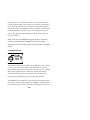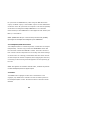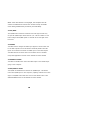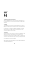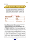
1
FIREstation
FireWire™ Recording Interface
User's Manual
VERSION 2.0
PreSonus Audio Electronics
Presonus Limited Warranty
Presonus Audio Electronics Inc. warrants this product to be free of defects in material and
workmanship for a period of one year from the date of original retail purchase. This warranty
is enforceable only by the original retail purchaser. To be protected by this warranty, the
purchaser must complete and return the enclosed warranty card within 14 days of purchase.
During the warranty period Presonus shall, at its sole and absolute option, either repair or
replace, free of charge, any product that proves to be defective on inspection by Presonus or
its authorized service representative. To obtain warranty service, the purchaser must first call
or write Presonus at the address and telephone number printed below to obtain a Return
Authorization Number and instructions of where to return the unit for service. All inquiries
must be accompanied by a description of the problem. All authorized returns must be sent to
the Presonus repair facility postage prepaid, insured and properly package. Proof of purchase
must be presented in the form of a bill of sale, canceled check or some other positive proof
that the product is in within the warranty period. Presonus reserves the right to update any
unit returned for repair. Presonus reserves the right to change or improve design of the
product at any time without prior notice. This warranty does not cover claims for damage due
to abuse, neglect, alteration or attempted repair by unauthorized personnel, and is limited to
failures arising during normal use that are due to defects in material or workmanship in the
product. Any implied warranties, including implied warranties of merchantability and fitness for
a particular purpose, are limited in duration to the length of this limited warranty. Some states
do not allow limitations on how long an implied warranty lasts, so the above limitation may
not apply to you. In no event will Presonus be liable for incidental, consequential or other
damages resulting from the broach of any express or implied warranty, including, among
other things, damage to property, damage based on inconvenience or on loss of use of the
product, and, to the extent permitted by law, damages for personal injury. Some states do not
allow the exclusion of limitation of incidental or consequential damages, so the above
limitation or exclusion may not apply to you. This warranty gives you specific legal rights, and
you may also have other rights, which vary form state to state. This warranty only applies to
products sold and used in the United States of America. For warranty information in all other
countries please refer to your local distributor.
Presonus Audio Electronics, Inc.
7257 Florida Blvd.
Baton Rouge, LA 70806
225-216-7887
www.presonus.com
i
Limited Warranty Outside of The U.S.
Presonus Audio Electronics products are warranted only in the country where purchased,
through the authorized Presonus distributor in that country, against defects in material and
workmanship. The specific period of this limited warranty shall be that which is described to
the original retail purchaser by the authorized Presonus dealer or distributor at the time of
purchase. Presonus does not, however, warrant its products against any and all defects: 1)
arising Out of materials or workmanship not provided or furnished by Presonus, or 2) resulting
from abnormal use of the product or use in violation of instructions, or 3) in products repaired
or serviced by other than authorized Presonus repair facilities, or 4) in products with removed
or defaced serial numbers, or 5) in components or parts or products expressly warranted by
another manufacturer. Presonus agrees, through the applicable authorized distributor, to
repair or replace defects covered by this limited warranty with parts or products of original or
improved design, at its option in each respect, if the defective product is shipped prior to the
end of the warranty period to the designated authorized Presonus warranty repair facility in
the country where purchased, or to the Presonus factory in the U.S., in the original packaging
or a replacement supplied by Presonus, with all transportation cost and full insurance paid
each way by the purchaser or owner. All remedies and the measure of damages are limited to
the above services. It is possible that economic loss or injury to person or property may result
from the failure of the product; however, even if Presonus has been advised of this possibility,
this limited warranty does not cover any such consequential or incidental damages. Some
states or countries do not allow the limitations or exclusion of incidental or consequential
damages, so the above limitation may not apply to you. Any and all warranties, express or
implied, arising by law, course of dealing, course of performance, usage of trade, or otherwise,
including but not limited to implied warranties of merchantability and fitness for a particular
purpose, are limited to a period of two years from either the date of original retail purchase or,
in the event no proof of purchase date is available, the date of manufacture. Some states or
countries do not allow limitations on how long an implied warranty last, so the above
limitations may not apply to you. This limited warranty gives you specific legal rights, and you
may also have other rights, which vary from state to state, country to country.
Presonus Audio Electronics, Inc.
7257 Florida Blvd.
Baton Rouge, LA 70806
225-216-7887
www.presonus.com
ii
Table of Contents
1.1 Introduction.....................................................................1
1.2 Notes on Computer-Based Recording........................................................... 1
2.1 Basic Setup & Applications................................................2
2.2 Computer Setup........................................................................................... 2
2.3 Recording..................................................................................................... 3
2.4 Mixing........................................................................................................... 3
2.5 Internal Mix Mode ........................................................................................ 4
2.6 External Mix Mode........................................................................................ 5
2.7 Stand-Alone Mode (Special ADAT Mode)...................................................... 6
2.8 Stand-Alone Mode (With DigiDesign 001™) ................................................. 7
2.9 ADAT Mode................................................................................................... 8
3.1 Features...........................................................................9
3.2 Switchable Preamps..................................................................................... 9
3.3 Zero-Latency Line-Mixer............................................................................... 9
3.4 Volume Control............................................................................................. 9
3.5 Clock Control................................................................................................ 9
3.6 mLAN/FireWire........................................................................................... 1 0
3.7 Footswitch Input......................................................................................... 1 0
3.8 MIDI 1 0
3.9 ADAT.......................................................................................................... 1 0
3.10 S/PDIF........................................................................................................ 1 1
3.11 B N C 1 1
4.1 Front Panel ....................................................................12
4.2 Preamps..................................................................................................... 1 2
4.3 Inputs......................................................................................................... 1 2
4.4 Meters........................................................................................................ 1 3
4.5 + 4 8 V.......................................................................................................... 1 3
iii
4.6 Pad 1 3
4.7 Zero-Latency Line Mixer............................................................................. 1 4
4.8 Channels One-Eight.................................................................................... 1 4
4.9 MLAN Return .............................................................................................. 1 5
4.10 Master Control............................................................................................ 1 6
4.11 Headphone/Main Out Control..................................................................... 1 7
4.12 Mixer.......................................................................................................... 1 7
4.15 S/PDIF........................................................................................................ 1 8
4.16 ADAT.......................................................................................................... 18
4.17 ADAT To mLAN........................................................................................... 1 8
4.18 S/PDIF To mLAN......................................................................................... 1 8
4.19 Clock .......................................................................................................... 1 9
4.20 External Control (Slave Mode) ................................................................... 1 9
4.21 B N C 1 9
4.22 m L A N ......................................................................................................... 1 9
4.23 ADAT.......................................................................................................... 2 0
4.24 INT 2 0
4.25 Buttonology Notes...................................................................................... 2 0
5.1 Back Panel.....................................................................21
5.2 IEC Power Connector.................................................................................. 2 1
5.3 Power On/Off.............................................................................................. 2 1
5.4 FireWire/IEEE 1394 I/O.............................................................................. 21
5.5 MIDI And S/PDIF Port ................................................................................ 2 2
5.6 MIDI Daisy-Chain Example......................................................................... 2 3
5.7 ADAT.......................................................................................................... 2 3
5.8 B N C 2 3
5.9 Footswitch Input......................................................................................... 2 4
5.10 TRS Line Ins/Outs ...................................................................................... 2 4
5.11 TRS Preamp Sends..................................................................................... 2 5
5.12 Main Out..................................................................................................... 2 5
iv
6.1 Top Panel.......................................................................26
6.2 Analog To Digital Converter Line Level Adjust............................................ 2 6
6.3 Heat Vent................................................................................................... 2 6
7.1 Software........................................................................27
7.2 Operating System ...................................................................................... 2 7
7.3 Recording Software.................................................................................... 2 7
8.1 Troubleshooting.............................................................28
8.2 The ADAT Input/Output Doesn’t Support Optical S/PDIF ........................... 2 8
8.3 Pops, Clicks, And/Or Distortion Are Present In The Audio Signal ............... 2 8
8.4 ADAT I/O Cannot Be Used In Conjunction With The Line Or S/PDIF I/O.... 2 8
8.5 The Preamps Noise Floor Is Higher When The Tube Drive Is Engaged....... 2 9
8.6 mLAN Returns Three And Four Do Not Work In ADAT Mode ...................... 2 9
8.7 Word Clock Synchronization (Sync) ........................................................... 2 9
8.8 MIDI ........................................................................................................... 3 0
8.9 Footswitch.................................................................................................. 3 0
8.10 Latency....................................................................................................... 3 0
8.11 Drivers ....................................................................................................... 3 1
8.12 Operating Systems..................................................................................... 3 1
8.13 N o n-Presonus FireWire/mLAN Devices....................................................... 3 1
8.14 Line-Mixer Doesn’t Work When Using FIREstation As Stand-Alone A-D ..... 3 2
8.15 The EXT Button Is Blinking......................................................................... 3 2
8.16 The Sample Rate LED Is Blinking ............................................................... 3 2
8.17 S/PDIF Feedback Loop ............................................................................... 3 2
9.1 Technical Specifications..................................................33
v
1.1 INTRODUCTION
Thank your for purchasing the Presonus FIREstation. We feel that we
have created a reliable, versatile and affordable piece of audio
equipment. It is designed to meet a multitude of professional digital
recording applications. If you have any questions or comments in
regards to this or any other piece of Presonus equipment, please feel
free to contact us!
1.2 NOTES ON COMPUTER-BASED RECORDING
The Presonus FIREstation is a recording interface only. Many problems
can arise when converting a standard computer into a DAW (Digital
Audio Workstation). Presonus only provides support for issues that
directly relate to the FIREstation. It may be necessary to contact the
manufacturer of the operating system or software to obtain additional
technical support. Presonus does not provide support for issues in
regards to operating systems, additional hardware or software. Please
check our website, www.presonus.com regularly for software,
firmware, and technical support updates.
1
2.1 BASIC SETUP & APPLICATIONS
2.2 Computer Setup
Place the provided driver’s software in your computer after powering it
up. If an install wizard appears, direct it to the provided CD-ROM when
prompted. If the install wizard does not appear, open the CD-ROM and
run the Auto Installer from there. Follow the directions on your screen.
NOTE: It is essential that the FIREstation not be connected to the
computer when the drivers are installed. If you accidentally leave the
FIREstation connected, disconnect the unit, uninstall the drivers,
reboot and then reinstall the drivers.
After the driver fully installs power down your computer. Turn off all
external devices before connecting the FIREstation(s). Connect all
external devices to the FIREstation(s). Power up the FIREstation and
then connect the FIREstation to the computer using the provided 6-pin
FireWire cable. Fasten your seatbelt and then power up the computer.
Three different items will be loaded on your computer at this point.
The first item that is loaded is the actual software driver. The driver
allows your computer to recognize and communicate with the
FIREstation. A control panel is also loaded. The control panel indicates
if the FIREstation is connected properly. It also indicates and helps
control sample rate and clock control (sync). A patchbay is also
loaded. The patchbay allows the user to route the inputs and outputs
of the FIREstation in computer. It is important to note that each
FIREstation has a unique Identity. So, if a FIREstation is connected
and routed, that routing scheme that is saved will only work for that
2
specific FIREstation. If a different FIREstation is added, it will need to
be rerouted.
2.3 Recording
When recording the headphone output can be used for headphone
monitoring and the main outs can be used for control room monitors.
This setup negates the need for an external mixer. The volume setting
of the Main/Headphone outs and the Line Mixer do not affect the
recording level.
2.4 Mixing
As far as the use of the FIREstation goes there are two different mix
modes: Internal and External. Each mode has its benefits that are
determined by your overall computer speed and capacity, familiarity
with recording software, and creativity.
3
2.5 Internal Mix Mode
SPEAKER
SPEAKER
COMPUTER
CD RECORDER
POWER
PreSonus
FIRESTATION
IN
MIDI - S/PDIF
(S/PDIF input and output
on channels 7/8)
FIREWIRE PORTS
1
CLOCK
MIC/INSTRUMENT
5
7
1
3
LINE OUTPUTS - TRS BALANCED
OUT
Created,
Designed and
Manufactured
In The USA
3
5
7
1
L
PREAMP
SEND - TRS
2
R
FOOTSWITCH
(Record Punch)
ADAT™
optical
2
4
6
8
LINE INPUTS - TRS BALANCED
2
4
6
8
MAIN OUT
115/230 VAC ~
By internal Jumper
30Watts
-32
-16
MIC/INSTRUMENT
CLIP
-32
48V
0
-16
DIRECT PATCH LINE MIXER
CLIP
48V
0
293
MIC/LINE IN 1/2
LINE IN 3/4
0
LINE IN 5/6
0
293
MASTER CONTROL
SPDIF/LINE IN 7/8
C
C
0
0
mLAN RETURN
M I X E R SPDIF
0
CLOCK
A D A T
EXT
INT
6
0
A D A T TS O
PDIF TO
m L A N m L A N
PAD
PAD
B M Cm L A A
N D A T
PREAMP 1
92
-12
494
+12
GAIN
TUBE
DRIVE
GUITAR
PREAMP 2
92
-12
GAIN
494
+12
TUBE
DRIVE
-80
+10
ONE
d B
TWO
Mono
-80
+10
THREE
d B
L
FOUR
Mono
-80
PAN
+10
d B
MICROPHONE
R
LEVEL
Stereo
L
-80
+10
PAN
d B
R
LEVEL
Stereo
-80
+10
1/2
d B
3/4
0
-80
PHONES
+10
d B
12
MAINOUT
32k 4 4 . 1 k 48k
Stereo
HEADPHONES
Internal mode signifies that you are using software and internal plugins to mix a project. In this instance only the master outputs and
headphone outputs would be used. The internal mode is preferred in
some situations dependent on the environment and other factors. For
example, wouldn’t it be nice to mix a song over headphones while
sitting in a hotel room between live performances?
4
2.6 External Mix Mode
SPEAKER
SPEAKER
COMPUTER
CD RECORDER
POWER
PreSonus
FIRESTATION
FIREWIRE PORTS
IN
MIDI - S/PDIF
(S/PDIF input and output
on channels 7/8)
ADAT™
optical
FOOTSWITCH
(Record Punch)
Created,
Designed and
Manufactured
In The USA
1
CLOCK
3
5
7
1
LINE OUTPUTS - TRS BALANCED
OUT
2
4
6
8
3
5
7
LINE INPUTS - TRS BALANCED
2
4
6
8
1
PREAMP
SEND - TRS
2
L
MAIN OUT
R
115/230 VAC ~
By internal Jumper
30Watts
GUITAR
MICROPHONE
MIXER
External mode incorporates other equipment beyond the FIREstation.
For example, an external mixer and other processors may be used. In
this mode, the outputs of the FIREstation could be routed to external
equipment for dynamics processing, effects and other forms of
manipulation. The master outputs could then be returned to two
channels of the FIREstation to record the “Master Mix”.
5
2.7 Stand-Alone Mode (Special ADAT Mode)
MASTER CONTROL
MIXER
SPDIF
ADAT
6
0
ADAT TO
mLAN
0
-80
PHONES
+10
dB
SPDIF TO
mLAN
12
MAIN OUT
The FIREstation can be set in stand-alone mode by pressing the Mixer
and ADAT buttons simultaneously. Stand-alone mode allows the
FIREstation to do two main things: act as an ADAT line mixer and
perform A/D and D/A conversion. The signal plugged into either the
ADAT I/O will be routed to the opposite set of analog ports. For
example, if a DigiMAX were plugged into the ADAT input, the same
signal would be sent to the TRS outputs. The line mixer would also
function, allowing the user to monitor all eight channels.
ADAT Input
Analog
Mixer
Line Outs
ADAT Out
NOTE: When using the FIREstation as an Analog to Digital (A-D)
converter, the line mixer does not contain the analog inputs, just the
ADAT inputs.
6
2.8 Stand-Alone Mode (With DigiDesign 001™)
COMPUTER
DIGIDESIGN 001™
POWER
PreSonus
FIRESTATION
FIREWIRE PORTS
IN
MIDI - S/PDIF
(S/PDIF input and output
on channels 7/8)
ADAT™
optical
FOOTSWITCH
(Record Punch)
Created,
Designed and
Manufactured
In The USA
1
CLOCK
3
5
7
1
LINE OUTPUTS - TRS BALANCED
OUT
2
4
6
8
3
5
7
LINE INPUTS - TRS BALANCED
2
4
6
8
1
PREAMP
SEND - TRS
2
L
MAIN OUT
R
115/230 VAC ~
By internal Jumper
30Watts
NOTE: You would want to be in ADAT special mode for this application.
7
2.9 ADAT Mode
MASTER CONTROL
MIXER
SPDIF
ADAT
6
0
ADAT TO
mLAN
0
-80
+10
dB
PHONES
SPDIF TO
mLAN
12
MAIN OUT
Another stand-alone mode occurs when just the ADAT button is
pressed. In this mode, the FIREstation acts as an ADAT line mixer or
converter. The ADAT signal can be converted to analog while being
routed through the line mixer. It is important to note that the analog
inputs are not functional in this mode.
Mixer
ADAT Input
Line Outs
ADAT Out
Analog Inputs
Nowhere
8
3.1 FEATURES
The following is a summary of the features of the FIREstation:
3.2 Switchable Preamps
The two preamps on the FIREstation can be switched between solidstate and tube driven. The outer knob of the preamp controls gain and
the inner knob controls tube drive. The tube drive is completely
disengaged when the knob is turned fully counter clockwise until the
knob clicks.
3.3 Zero-Latency Line Mixer
The FIREstation utilizes an onboard line mixer that eliminates latency
(monitoring delay). Every channel of the FIREstation can be routed to
the onboard line mixer. The mixer can be functional whether
connected to a computer or not.
3.4 Volume Control
The dual concentric volume control knob controls the amount of
volume to the headphone jack on the inner knob and to the master
outputs on the outer knob.
3.5 Clock Control
The FIREstation has BNC Word Clock connectors for external (slave)
and internal (master) Word Clock sync. A MIDI I/O is provided for
additional machine control including MTC, MMC, and MIDI. The ADAT
I/O can also provide or carry Word Clock as well.
9
3.6 mLAN/FireWire
The FIREstation utilizes the mLAN protocol. This standard allows the
unit to be connected to and share information with a multitude of
digital devices. mLAN is an advanced network protocol that allows
multiple FIREstations and/or other digital devices to be interconnected.
Examples of these devices would be: external hard drives, digital
camcorders, and synthesizers.
3.7 Footswitch Input
The footswitch input on the back of the unit allows the user to start
and stop recording at any desired moment. Every different software
manufacturer requires a different setup for use of this footswitch
receptacle. Please consult your software manufacturers manual,
website, or customer support for proper setup of this feature. The
FIREstation does not come equipped with a footswitch. (The footswitch
must be purchased separately.)
3.8 MIDI
MIDI stands for ‘Musical Instrument Digital Interface’. However, the
MIDI standard goes well beyond sequencing. The MIDI I/O allows
connection or communication with external MIDI equipment. One
function of this port is MIDI programming. This port can also be used
for MMC (MIDI Machine Control), MTC (MIDI Time Control), and
sequencing.
3.9 ADAT
The ADAT I/O allows interconnectivity between the FIREstation and
devices using ADAT I/O. The fiber-optic input does not support Optical
S/PDIF (two channels). The ADAT standard allows up to eight channels
10
of audio, at up to 24-bit 48k resolution, to be transferred
simultaneously in one direction.
3.10 S/PDIF
The S/PDIF I/O allows the FIREstation to transfer/receive audio from
other digital audio devices.
3.11 BNC
The BNC I/O is designed to allow the FIREstation to sync frame rates
with other digital devices. This sync prevents pops, clicks and
distortion.
11
4.1 FRONT PANEL
MIC/INSTRUMENT
-32
-16
-3
(dBfs)
MIC/INSTRUMENT
-32
-16
-3
DIRECT PATCH LINE MIXER
(dBfs)
MIC/LINE IN 1/2
48V
26
10
48V
26
10
LINE IN 3/4
0
LINE IN 5/6
0
MASTER CONTROL
SPDIF/LINE IN 7/8
C
0
mLAN RETURN
C
0
M I X E R SPDIF
0
CLOCK
A D A T
6
0
EXT
INT
A D A T TS O
PDIF TO
m L A N m L A N
18
44
18
44
PAD
PAD
B M Cm L A A
N D A T
10
( C L I C K )
PREAMP 1
T U B E
O F F
G A I N
20
54
TUBE
DRIVE
10
( C L I C K )
PREAMP 2
T U B E
O F F
G A I N
20
54
TUBE
DRIVE
-80
+10
-80
+10
dB
ONE
Mono
dB
TWO
THREE
FOUR
Mono
L
-80
+10
dB
PAN
Stereo
R
LEVEL
L
-80
+10
dB
PAN
Stereo
R
LEVEL
-80
+10
dB
1/2
3/4
0
-80
PHONES
dB
+10
12
MAIN OUT
32k 4 4 . 1 k 48k
Stereo
4.2 Preamps
The two preamps on the FIREstation are switchable. They can be
changed between solid-state and tube driven. The tube drive is
deactivated when the inner knob of the preamp is turned fully counterclockwise. This stage is indicated by a click when the knob is turned
fully counter-clockwise. The inner knob on each channel controls the
amount of signal routed to the 12AX7 vacuum tube. This feature lets
you control how much saturation of the signal occurs. Greater levels of
tube saturation give the signal greater warmth and a richer sound or
desirable distortion in extreme cases. This works equally well on mics
and instruments.
NOTE: Fully engaging the tube drive may increase the noise floor.
NOTE: It is recommended that the Control Room and Headphone
volumes be turned all the way down when the tube drive is initially
turned on.
4.3 Inputs
Each preamplifier has a Neutrik combo connector input. The input
accepts either XLR or 1/4” instrument inputs. The 1/4” or Hi-Z input is
designed for use with a guitar, bass, etc. This input is not a line level
input.
12
4.4 Meters
The input meters above the preamps indicate signal strength. Turning
the preamps gain control too far clockwise could cause the preamp to
clip. The clip indicator light will be illuminated at this point. In order to
overdrive the input while still maintaining a useable recording level a
compressor/limiter is needed. Several high quality
compressors/limiters are available from Presonus. Some examples of
these products are the BlueMAX, ACP22, ACP88, and CL44. Please
refer to www.presonus.com for more details on these fine products.
4.5 +48V
Each preamp has a +48 volt phantom power switch. Phantom power is
required for some microphones. These microphones are referred to as
electrostatic or condenser. These microphones require an external
power source in order to operate.
4.6 Pad
A –20 dB pad is provided on each preamp. The pad drops the signal by
–20dB to accommodate higher level (louder) signals. The pad is
especially useful when using microphones that require phantom power.
NOTE: Often times phantom powered microphones produce a higher
level (louder) output, which is why the pad is useful when using these
(phantom/condenser) microphones.
13
4.7 Zero-Latency Line Mixer
DIRECT PATCH LINE MIXER
MIC/LINE IN 1/2
LINE IN 3/4
0
-80
+10
-80
dB
ONE
LINE IN 5/6
0
+10
dB
TWO
Mono
THREE
FOUR
Mono
SPDIF/LINE IN 7/8
C
0
L
-80
+10
dB
PAN
mLAN RETURN
C
0
R
LEVEL
Stereo
L
-80
0
+10
dB
PAN
R
LEVEL
-80
+10
dB
1/2
Stereo
3/4
Stereo
All 12 channels of the line mixer are routed directly to the
Headphone/Main Output volume control knobs/outputs. Every two/four
(according to the signal designation) channels are grouped together
sequentially to one dual concentric knob.
4.8 Channels One-Eight
The first two knobs allow for independent channel volume control
without panning (one and two, three and four). The amount of volume
given to each channel dictates the amount of volume to the
headphone/main out. The second two knobs group the channels in
stereo pairs (five and six, seven and eight). The inner part of the knob
controls the amount of signal (volume) that goes to the
headphone/main control and the outer ring controls panning. Each pair
of channels is routed directly to the headphone/main outputs.
Therefore, the FIREstation can be used as a line mixer without
connection to a computer. There is no latency or delay between the
time the signal hits the respective input and goes to the
headphone/main output. This routing scenario ensures that what is
heard through the headphone/main output is occurring at exactly that
moment.
14
4.9 mLAN Return
The last knob of the FIREstation line mixer is dedicated to channels
assigned to the unit by the computer. These channels are the channels
routed to outputs one-four (TRS line out) on the FIREstation. These
knobs differ from the others in that there is no pan assignment. The
outer ring controls the line mixer volume of returning channels one
and two and the inner ring controls the returning channels volume of
three and four. The computer dictates panning on this dual concentric
knob. If channels are not routed to the FIREstation by the computer,
they will not be able to be monitored by the line mixer from either
output.
NOTE: The speed of the computer will determine the amount of signal
delay (latency) to these inputs. If a significant amount of delay is
noticed, the computer or software manufacturer may need to be
consulted to improve performance.
When the S/PDIF input is selected, it is automatically routed to
channels seven and eight. It is not possible to route this pair of inputs
to any other input channels. This is similar to when the ADAT input is
engaged. When the ADAT input is selected, it occupies channels one
through eight. The analog and S/PDIF inputs are not useable at this
point. This feature is especially useful when using the DigiMAX or
DigiMAX LT (microphone preamplifiers manufactured by Presonus) on
the ADAT input. This feature eliminates the need for external mixing
equipment.
The last channels on the line mixer are reserved for two to four
channels returning from the computer. These channels allow you to
15
monitor what you have already recorded in conjunction with what is
currently being recorded. The signals sent to these four channels are
set on the computer itself. These channels are the physical channels
that are returned to the FIREstation from the computer. These returns
would be FIREstation outputs one-four. It is also important to note
that when in ADAT/Stand Alone mode that mLAN returns three and
four are not active.
NOTE: These two pairs (FIREstation outputs one-four) of channels
cannot be reassigned using the FIREstation itself. Any channel
redistribution must be configured using the host software or operating
system.
4.10 Master Control
MASTER CONTROL
MIXER
SPDIF
ADAT
6
0
ADAT TO
mLAN
0
-80
PHONES
+10
dB
SPDIF TO
mLAN
12
MAIN OUT
The DIGITAL section of the faceplate of the FIREstation refers to clock
control. Clock control is necessary to provide stability in recording
digital material. Word Clock is the common protocol used for synching
digital audio recording devices. Word Clock ensures that different
devices maintain the same recording frame rate. This frame rate
protocol prevents digital dropout, clicks, pops, and distortion.
The FIREstation has two different clock modes, INT (internal) and EXT
(external). The internal option allows the FIREstation to stand alone or
be the master. When using the INT mode, other digital devices could
16
be synched to the FIREstation by either using the BNC Word Clock
output, the ADAT output, or the FireWire output. The EXT mLAN mode
causes the unit to be synched to the computer. This mode is especially
useful when recording with multiple FIREstations. The other EXT
modes would sync the FIREstation to other digital devices either by the
BNC in, or the ADAT in.
NOTE: S/PDIF external sync is not necessary because the (S/PDIF)
input signal is resampled and realigned by the FIREstation.
4.11 Headphone/Main Out Control
The headphone/main out control respectively controls the two outputs
independently. The inner ring controls the HEADPHONE volume and
the outer knob controls the MAIN OUT volume. The audio content of
both volume controls is dependent on the routing and volume settings
of the line mixer. It is strongly recommended that the volume of both
of these outputs be lowered completely when engaging the tube drive,
connecting or disconnecting external equipment or when powering up
the unit.
NOTE: If a signal is not routed to the line mixer, it will not be present
in either headphone/main out signal output.
4.12 Mixer
The MIXER button engages the line mixer. If this button is not
engaged, only mLAN return channels one and two will be present in
the Headphone/Main out mix. All other functions of the mixer will be
disabled.
17
NOTE: if the mixer button is not engaged, the computer sets the
volume of mLAN returns one and two. In other words, the mLAN
return knob (potentiometer) is inactive (non-functional).
4.13 S/PDIF
The S/PDIF button switches channels seven and eight so that they
accept the S/PDIF input rather than the 1/4” TRS in or ADAT In. This
button assigns the S/PDIF inputs to channels seven and eight of the
line mixer.
4.14 ADAT
The ADAT button assigns the ADAT input signal to the line mixer and
to the TRS outputs as well. This button essentially defeats the TRS
inputs to the mixer and mirrors the ADAT input on the TRS outputs.
The ADAT button has other uses as well. Please refer to the Basic
Setup And Applications section of this manual for further details.
4.15 ADAT To mLAN
The ADAT to mLAN button routes the ADAT input to the mLAN output
going to the computer.
4.16 S/PDIF To mLAN
The S/PDIF to mLAN button activates the S/PDIF input. This button
routes the S/PDIF input to the computer, replacing channels seven and
eight. The S/PDIF button has other uses as well. Please refer to the
APPLICATIONS section of this manual for further details.
18
4.17 Clock
CLOCK
EXT
BMC
32k
INT
mLAN ADAT
44.1k
48k
4.18 External Control (Slave Mode)
When the FIREstation is set to EXT, Word Clock is determined or set
by an external device. The three external controllers are BNC, mLAN,
and ADAT.
4.19 BNC
The FIREstation can be synced to another digital device by using the
BNC input. The BNC output could also be used to control other devices
by Word Clock. For example the DigiMAX and DigiMAX LT (preamps
made by Presonus) use BNC outputs to send Word Clock to other
devices for sample accurate recording.
4.20 mLAN
mLAN would be the most common clock mode for the FIREstation. This
allows the computer to be the master clock. Word Clock is then
transferred to external devices via FireWire or BNC. The sampling rate
would be set in the mLAN control panel. Currently, mLAN protocol uses
two sampling rates: 44.1kHz and 48kHz.
NOTE: All other clock modes allow the use of the 32kHz sampling rate,
even though mLAN does not.
19
4.21 ADAT
ADAT mode would slave the FIREstation(s) to an external device that
utilized an ADAT optical output. The unit would automatically sync
itself to the sampling rate of the external device. The ADAT mode
would most likely be used when a BNC output is not present on the
external device.
4.22 INT
Three different sample rates are available. These rates are 32k, 44.1k,
and 48k. The higher the resolution, the more hard drive space
required. For example, one minute of stereo recording at 44.1kHz
requires 10 MB of hard drive space per minute.
NOTE: The FIREstation always records at a 24-bit resolution. In order
to record at a lower resolution, the software has to be set to dither or
truncate the incoming recording signal.
4.23 Buttonology Notes
If the EXT clock button blinks, then no clock is present for the
FIREstation to be slaved to the external device.
If the LED for Sample rate/external device blinks, then signal is out of
the sampling range.
20
5.1 BACK PANEL
POWER
PreSonus
FIRESTATION
FIREWIRE PORTS
IN
MIDI - S/PDIF
1
ADAT™
optical
CLOCK
5
7
1
LINE OUTPUTS - TRS BALANCED
OUT
Created,
Designed and
Manufactured
In The USA
3
3
5
7
1
L
PREAMP
SEND - TRS
MAIN OUT
2
R
FOOTSWITCH
(Record Punch)
(S/PDIF input and output
on channels 7/8)
2
4
6
8
LINE INPUTS - TRS BALANCED
2
4
6
8
115/230 VAC ~
By internal Jumper
30Watts
5.2 IEC Power Connector
POWER
PreSonus
FIRESTATION
115/230 VAC ~
By internal Jumper
30Watts
Please pay close attention before plugging in your FIREstation for the
first time. Make sure that the voltage printed on the unit matches that
provided by your country or region.
5.3 Power On/Off
The Power on/off switch controls power to the FIREstation. It is
strongly recommended that the unit be powered off between uses.
5.4 FireWire/IEEE 1394 I/O
FIREWIRE PORTS
21
The IEEE1394 ports are 6-pin connectors. Both ports are bi-directional.
They send and receive data from the other interconnected devices.
IEEE 1394 compatible devices such as keyboards, computers,
camcorders, etc. may be connected to the FIREstation using these
ports.
5.5 MIDI And S/PDIF Port
MIDI - S/PDIF
(S/PDIF input and output
on channels 7/8)
An external breakout cable is provided with the FIREstation to provide
MIDI I/O and S/PDIF I/O. The S/PDIF I/O accepts a coaxial plug and
does not accept an optical plug without a converter (coaxial to optical
and vice-versa).
All signals that are sent to the S/PDIF input of the FIREstation do not
need to carry Word Clock. The input S/PDIF signal is re-sampled,
therefore (in this instance) the FIREstation can remain in the present
Clock mode and BNC cables are not needed. However, this is not the
case with signals sent from the Firestation’
s S/PDIF outputs. Word
Clock signal can be sent either by BNC or S/PDIF. Correct Word Clock
22
sync can prevent pops, clicks or distortion on external recording
devices (such as mini-disk recorders, DAT recorders, or CD
Recorders).
5.6 MIDI Daisy-Chain Example
POWER
PreSonus
FIRESTATION
FIREWIRE PORTS
IN
MIDI - S/PDIF
(S/PDIF
on
input
and
channels
FOOTSWITCH
(Record Punch)
output
7/8)
ADAT™
optical
Created,
Designed
115/230
and
By
Manufactured
In The USA
VAC
internal
1
CLOCK
3
5
7
1
LINE OUTPUTS - TRS BALANCED
OUT
2
4
6
8
3
5
7
LINE INPUTS - TRS BALANCED
2
4
6
8
1
PREAMP
SEND - TRS
2
L
MAIN OUT
R
~
Jumper
30Watts
SAMPLER
DRUM MACHINE
KEYBOARD
5.7 ADAT
The ADAT I/O allows interconnectivity between the FIREstation and
devices using ADAT I/O. The Fiber optic input does not support Optical
S/PDIF (two channels). The ADAT standard allows eight channels of
audio, at up to 24 bit 48k resolution, to be transferred simultaneously.
5.8 BNC
IN
(Record Punch)
CLOCK
OUT
The BNC I/O is designed to allow the FIREstation to sync frame rates
with other digital devices. This sync prevents pops, clicks and
distortion.
23
5.9 Footswitch Input
The footswitch on the back of the unit allows the user/engineer to start
and stop recording at any desired moment. Every different software
manufacturer requires a different setup for use of this footswitch
receptacle. Please consult your software manufacturers manual,
website, or customer support for proper setup of this feature. The
FIREstation does not come equipped with a footswitch, it must be
purchased separately.
NOTE: The footswitch operates on Channel 16 with Controller 23 with
the Value set to 127.
5.10 TRS Line Ins/Outs
1
3
5
7
1
8
2
3
5
7
1
8
2
L
FOOTSWITCH
(Record Punch)
LINE OUTPUTS - TRS BALANCED
2
4
6
PREAMP
SEND - TRS
LINE INPUTS - TRS BALANCED
4
6
MAIN OUT
R
The TRS inputs and outputs are designed for use with balanced or
unbalanced 1/4” cables. Balanced cables have an extra conductor and
allow a signal to be sent over a longer distance while maintaining a
lower noise floor. The TRS line inputs for channels one and two take
precedent over preamp channels one and two. This is done so that
another device may be placed between the preamp sends and the TRS
line inputs.
24
5.11 TRS Preamp Sends
The TRS sends are designed for use with balanced or unbalanced 1/4”
cables. The sends are direct outputs from the preamp that allow an
external dynamics processor to be placed in the signal chain. For
example, a BlueMAX or similar compressor could be wired in place
between the sends and any of the FIREstationin puts. Proper attention
must be paid so that the sends from the preamp are connected to the
inputs of the external device and the outputs of the device are
connected to the inputs of the FIREstation.
5.12 Main Out
The Main outs are designed for use with Control Room Monitors. The
line mixer dictates the content and volume of these outputs.
25
6.1 TOP PANEL
6.2 Analog To Digital Converter Line Level Adjust
Analog to Digital Converter
Line Level Adjust
1
2
3
4
5
6
7
8
There is typically a 14dB difference between the 0dB reference levels
in analog and digital equipment. The line level adjust on the
FIREstation allows the user to adjust the 0dB reference to match that
of an external analog device such as a preamp or console. A tweaker
or small Phillips screwdriver can be used to adjust this level. Turn the
tweaker clockwise to raise the 0dB level and counter-clockwise to
lower the level.
For example: If you were running a Presonus M80 into your
FIREstation, you may notice that you could go into the red on the
M80’s meters while the recording software would maintain a relatively
low recording level. You could adjust the FIREstation converters so
that the software would have the same meter reading as the M80.
6.3 Heat Vent
The FIREstation has three heat vents. The vent on the top of the unit
is directly over the power transformer. It is strongly recommended
that there be at least one rack space open above the unit for proper
cooling. Anything placed directly on top of any of the three vents could
cause the unit to overheat and malfunction.
26
7.1 SOFTWARE
7.2 Operating Systems
The FIREstation is designed for use with Windows XP and Macintosh
OS 9.x. Other operating systems are not currently supported by
Presonus or Yamaha.
7.3 Recording Software
The FIREstation currently utilizes ASIO drivers for multi-channel
recording/playback and WDM drivers for stereo recording/playback.
Please check that your recording software utilizes the appropriate
drivers for the specific application. To toggle between ASIO and WDM
mode use the provided Yamaha mLAN control panel. To change into
WDM mode, simply check the WDM box on both the send and receive
side of the control panel. It is also necessary to hit the APPLY button in
the patchbay after switching between drivers. In WDM mode the
computer will recognize inputs/outputs one and two.
NOTE: If you change anything in the control panel or patch bay you
must hit the APPLY button in the patch bay. Otherwise your changes
will not take effect.
27
8.1 TROUBLESHOOTING
8.2 The ADAT Input/Output Doesn’
t Support Optical S/PDIF
The ADAT input/output does not support optical S/PDIF. Optical
S/PDIF is characterized by utilizing two channels, rather than eight.
S/PDIF is carried by a pair of coaxial (RCA-style) plugs on the breakout
cable.
8.3 Pops, Clicks, And/Or Distortion Are Present In The Audio
Signal
Pops, clicks and distortion on the fiber optic I/O may be caused by
Word Clock discrepancies. Word Clock problems arise when the digital
frame rates of two devices are not aligned. In order for two or more
digital devices to be properly aligned only one device can be set as
master. Word Clock allows other deices to be synced or ‘chained’to
this device. In other words, the ‘
chained’devices are set as slaves.
(Similar to a MIDI daisy-chain). The BNC connectors allow one unit to
be slaved to another unit, which is one way to sync two or more digital
devices. Another way to sync digital Word Clock devices is through the
Word Clock signal that is carried either by the S/PDIF I/O or the ADAT
I/O.
8.4 ADAT I/O Cannot Be Used In Conjunction With The Line Or
S/PDIF I/O
The ADAT I/O cannot be used at the same time as the line or S/PDIF
I/O. For example, ADAT channels one-six and S/PDIF cannot be used
simultaneously. However, you can use the ADAT inputs and the Line
outputs at the same time. In this instance the line outputs will mirror
the ADAT inputs.
28
The S/PDIF Inputs Cannot Be Routed to Other Channels on the Line
Mixer
By default, the S/PDIF I/O is ALWAYS assigned to channels seven and
eight. This cannot be changed.
8.5 The Preamps Noise Floor Is Higher When The Tube Drive Is
Engaged
Engaging the tube drive could increase the amount of noise in the
source signal. Turning up the tube drive and the gain simultaneously
could also increase the noise floor. However, mixing the amount of
tube drive and preamp gain can create interesting effects and sounds.
8.6 mLAN Returns Three And Four Do Not Work In ADAT Mode
mLAN returns three and four are not useable when in ADAT or in stand
alone mode. All return channels must be routed to channels one and
two in order to be monitored.
8.7 Word Clock Synchronization (Sync)
If you experience pops, clicks or distortion while recording it may be
due to incorrect Word Clock sync. Only one device can be the master
and all the rest must be slaved. For most applications, the computer
will be the master. In this instance, the FIREstation will be set to EXT
and mLAN. If the ADAT output of the FIREstation is connected to
another device such as a digital mixer, it is recommended that the
BNC output be connected to the BNC input of the receiving device (in
this case the external digital mixer).
29
8.8 MIDI
If your FIREstation's MIDI I/O does not function or functions
irregularly, please first check that all cables are connected properly. It
may also be necessary to check the integrity of the cable as well.
Please also check the MIDI channel of each connected device. If the
channel setting of the sending and receiving device does not match,
MIDI information will not be properly sent/received. Also check to
insure that MIDI is connected in the patch bay.
Presonus does not provide support for issues in regards to operating
systems, additional hardware or software. Please check our website,
www.presonus.com regularly for software, firmware, and technical
support updates.
8.9 Footswitch
The footswitch operates on Channel 16 with Controller 23 with the
Value set to 127.
8.10 Latency
If a doubling effect or extreme delay is noticed on a signal that is
currently being recorded, it may be necessary to alter/disable the
monitoring setup in the recording software. A quick solution to this
problem would be to lower the levels of the mLAN return that the
signal is routed to.
In the instance that there is a delay in playback, the recording
software may need to be modified to achieve better performance.
Another factor in playback latency is the speed of the computer. The
30
computer/software manufacturer may need to be contacted for
performance issues.
8.11 Drivers
Currently the FIREstation supports multi-channel recording/playback
utilizing ASIO drivers. If your recording software does not recognize
the FIREstation either the driver hasn’t been loaded properly or the
recording software requires the user to run a separate setup/profiling
application.
WDM drivers are currently provided for stereo use ONLY. The
computer will solely recognize Inputs/Outputs one and two.
Presonus does not provide support for issues in regards to operating
systems, additional hardware or software. Please check our website,
www.presonus.com regularly for software, firmware, and technical
support updates.
8.12 Operating Systems
The FIREstation is designed for use with Windows XP and Macintosh
OS 9.x and higher. Presonus or Yamaha does not currently support
other operating systems.
8.13 Non-Presonus FireWire/mLAN Devices
Other FireWire devices are not covered by the Presonus warranty or
technical support. It may be necessary to contact the devices
manufacturer or retailer for added assistance or technical support.
31
8.14 Line Mixer Doesn’
t Work When Using FIREstation As
Stand-Alone A-D
When using the FIREstation as an Analog to Digital (A-D) converter,
the line mixer does not contain the analog signal.
8.15 The EXT Button Is Blinking
The External If the EXT clock button blinks then no clock is present for
the FIREstation to be slaved to.
8.16 The Sample Rate LED Is Blinking
If the LED for Sample rate/external device blinks, then signal is out of
the sampling range.
8.17 S/PDIF Feedback Loop
If you connect the S/PDIF input to the S/PDIF output you will create a
feedback loop. In other words you will hear some strange stuff.
32
9.1 TECHNICIAL SPECIFICATIONS
Preamp Bandwidth ..................................................10Hz to 50kHz
Preamp Input Impedance ..............................................1.3k Ohms
Instrument Input Impedance............................................2M Ohms
Preamp THD....................................................................0.002%
Residual Noise Floor...........................................................-96dBu
Preamp Gain ...................................................................... 70dB
TRS Input Impedance ....................................................10k Ohms
TRS Input Nominal Level .................................................... +4dBu
TRS Output Impedance .................................................... 51Ohms
TRS Output Nominal Level .................................................. +4dBu
TRS Main Outputs Impedance........................................... 51 Ohms
TRS Main Outputs Nominal Level.......................................... +4dBu
Headphone Output .................................................100mW 20-20k
Preamp Pad........................................................................ 20dB
Phantom Power........................................................... 48V +/- 2V
Meter............................................-20dBu, -10dBu, Clip at +18dbu
Internal Supply.................................................................. Linear
Analog to Digital Converters............................ 24-bit / 44.1K or 48K
ADC Dynamic Range...........................................................107db
DAC.............................................................24-bit / 44.1K or 48k
DAC Dynamic Range...........................................................107db
DAC Noise Floor................................................................. -96dB
Internal Word Clock Jitter............................................... Ultra-Low
mLan™ Speed ...............................................................200mbps
33