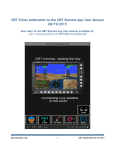
1
Installation, Setup, and User Manual
Revision A3
16-Jul-2014
Mini-B Installation, Setup & User Manual
GRT Avionics
Copyright© 2014
3133 Madison Ave. SE
Wyoming, MI 49548
(616) 245-7700
www.grtavionics.com
2
Revision A3
Mini-B Installation, Setup & User Manual
GRT Avionics
Mini-B Manual Revision Notes
Revision
Date
Change Description
A
23-May-2014 Initial Release
A1
29-May-2014 Section 2.3, clarified reason to isolate Mini from engine starter circuit
A2
16-Jun-2014
A3
16-Jul-2014
Appendix, A.1.5 and A.1.6- Corrected and clarified AHRS and Air Data Software
update instructions.
Added & clarified wiring options for Trig TT21/TT22 remote transponder,
Section 2.5
Added TT22 to list of choices for RS-232 serial ports, Section 2.6
3
Revision A3
Mini-B Installation, Setup & User Manual
GRT Avionics
Thank you for choosing GRT Avionics!
We hope you enjoy your new avionics system for many years to come.
Warranty & Return Policy
All GRT products include a 2-year warranty starting on the day the instrument is put into service (or
three years after purchase, whichever comes first) against manufacturer defect.
Please contact Tech Support before returning a display unit or component to GRT for repair or
warranty work. Many issues are installation or software-related and can be resolved over the phone,
saving time and expense. Please keep in mind that the minimum bench charge for EFIS units is $100.
All returns for repair or upgrade must be accompanied by a Service Request Form, downloadable
from the GRT website Support section.
Satisfaction Guarantee– If for any reason you are unhappy with your GRT product, you may return
it for a refund anytime during the first 60 days you own it. Some restrictions apply. Please call GRT
Tech Support before returning any system or component.
Technical Support
Our tech support staff has many years of real-world experience installing, flying and
troubleshooting GRT equipment in many different types of aircraft. We are here to make sure your
project succeeds.
Tech Support Hours
Monday-Friday 9:00 AM-12:00 PM and 1:00 PM -4:00 PM Eastern Time
(616) 245-7700 (EFIS Support phone menu option) or [email protected]
24-Hour Tech Support: The GRT Online Forum
Many questions may already have answers posted in our Online User Forum. Join today for free!
www.grtavionics.com/forum
4
Revision A3
Mini-B Installation, Setup & User Manual
GRT Avionics
Table of Contents
Section 1: Introduction
1.1 About the Mini-B…………………………………………………………………………………………………….. 7
1.2 Tools & References for Installation…………………………………………………………………………. 7
1.3 Mini System Requirements……………………………………………………………………………………… 7
1.4 AHRS Specifications and Limitations……………………………………………………………………….. 8
Fig 1-1 Mini Dimensional Drawing………………………………………………………………………………………. 9
1.5 Basic Controls of the Mini……………………………………………………………………………………….. 10
Section 2: Wiring Considerations
2.1 Mini-B Connector Definitions…………………………………………………………………………………. 12
Fig 2-1 Mini-B Rear Case/Connector Diagram……………………………………………………………………. 13
2.2 General Wiring Guidelines………………………………………………………………………………………. 14
2.3 Power Connections………………………………………………………………………………………………….. 14
2.4 Inter-Display Communication……………………………………………………………………………….….. 15
2.5 Trig TT21/TT22 Transponder Interface…………………………………………………………………….. 16
2.6 General Serial Port Wiring Information……………………………………………………………………. 17
Section 3: Mechanical Installation
3.1 Placement of the Mini on the Instrument Panel…………………………………………………….. 18
3.2 Mounting Hardware………………………………………………………………………………………………… 18
3.3 Pitot/Static Connections………………………………………………………………………………………….. 18
3.4 Cooling Considerations……………………………………………………………………………………………. 18
Section 4: General Setup & Calibration
4.1 Boot-Up Check………………………………………………………………………………………………………… 19
4.2 Explore the Set Menu Pages……………………………………………………………………………………. 19
4.3 Set Up Your General Preferences…………………………………………………………………………………. 20
5
Revision A3
Mini-B Installation, Setup & User Manual
GRT Avionics
Table of Contents continued…
4.4 Set Instrument Orientation……………………………………………………………………………………… 22
4.5 Set Final Instrument Orientation– Flight Test………………………………………………………….. 23
4.6 Altimeter Calibration……………………………………………………………………………………………….. 23
Section 5: Primary Flight Display
5.1 Primary Flight Display Overview………………………………………………………………………………. 26
5.2 Airspeed Tape………………………………………………………………………………………………………….. 27
5.3 Altimeter Tape….….………………………………………………………………………………………………….. 28
5.4 Vertical Speed Indicator…………………………………………………………………………………………… 29
5.5 Track Indicator…………………………………………………………………………………………………………. 29
5.6 Attitude Instruments………………………………………………………….…………………………………….. 30
5.7 Flight Path Marker…………………………………………………………………………………………………… 32
Section 6: Flight Planning & Navigation
6.1 GPS CDI Bar…………………………….………….…….……………………………………………………………… 33
6.2 Flight Planning with the Mini………………………………………………………………………………….. 33
6.3 Airport/Facilities Information and Radio Tuning……………………………………………………… 39
Section 7: Miscellaneous Features
7.1 Trig TT21/TT22 Remote Transponder………………………………………………………………………. 40
7.2 Data Recording………………………………….…………………………………………………………………….. 42
Appendix
A.1 Software Updates………………………………….………………………………………………………………….. 45
6
Revision A3
Mini-B Installation, Setup & User Manual
GRT Avionics
Section 1: Introduction
1.1 About the Mini-B
We designed the Mini with two main goals in mind: A small, lightweight, economical VFR EFIS
system for LSA and light kitplanes, and an affordable, high-quality backup to larger EFIS systems
for IFR operations. The Mini utilizes the same pilot interface as the popular Horizon and Sport
series; If you already use GRT avionics for your primary flight display, you will not have to remember
a different brand’s “buttonology” in an IFR emergency. The Mini has a built-in GPS for navigation,
so you will always know where you are.
In addition to the basic backup flight instruments, all models of the Mini can also serve as a serial
altitude encoder for any modern transponder, and serve as a control head for a remote Trig TT22
transponder. To top it off, the brilliant 1200-nit, high-resolution display shared by all three Mini
models ensures great visibility in all lighting conditions.
1.2 Tools & References for Installation
In addition to basic mechanical hand tools, a D-sub pin crimper is required in most installations.
A basic 4-way indent crimper is available from SteinAir for less than $35. We supply a few loose
male and female pins with your wiring harness, and we have them available for sale if you need
more.
If you are new to electrical systems and wiring, we highly recommend reading
by Bob Nuckolls. This book has been around for almost 30 years and covers everything
a homebuilder needs to know about how electrical systems work, how to design them, and how
to build them. There are also numerous online video tutorials by EAA, SteinAir and others in the
experimental aircraft community on wiring technique and electrical system design.
1.3 Mini System Requirements
The Mini utilizes the following systems for operation:
Ÿ Aircraft Power (12- or 28-volt system) - 0.25 Amp current draw at full brightness
Ÿ Pitot/static connection for flight instrumentation
Ÿ Built-in GPS with a remote “puck” antenna which must be within view of the sky at all times.
7
Revision A3
Mini-B Installation, Setup & User Manual
GRT Avionics
1.4 AHRS Specifications and Limitations
Ÿ Maximum Angular Rate: 250 deg/sec
Ÿ Maximum G-Limit : 4 G’s for unlimited time, 10 G’s for up to 20 seconds. Exceeding these limits
will not damage the instrument.
Ÿ Ambient Temperature Range for full accuracy: -10°F to +150°F
Ÿ Airspeed Range : 20-335 mph IAS
Ÿ Altimeter Range : -2000 to +40,000 feet
Ÿ Aiding Requirements for Attitude data: External Magnetometer, or GPS position data. Loss of
both results in loss heading reference. Extended periods with no aiding could reduce the accuracy
of the attitude data.
1.4.1 AHRS and Loss of GPS Data
Initial alignment
At power-up the AHRS performs an “alignment”. This allows the AHRS to provide attitude with
minimal or no aiding after alignment is complete. The alignment of usually complete by the time
the EFIS has booted up, and is providing a display. The alignment will complete more quickly if
the airplane is held motionless on the ground. If too much motion occurs during alignment, it is
possible that alignment will not complete until GPS track information is available. (GPS track
requires the GPS is to provided valid position data, and the airplane to be moving.)
Normal Operation
Attitude data will be full accuracy when valid GPS ground track data is available. If GPS ground
track data is lost (because the airplane is moving less than 4 mph, or the GPS is not able to provide
position data), the AHRS will attempt to use its internal magnetometer. If the internal magnetometer
is too inaccurate due to magnetic disturbances near the instrument, the ground track display on
the PFD screen will show dashes. The AHRS will provide full accuracy attitude information for at
least 5 minutes.
CAUTION: If the EFIS is unable to provide GPS ground track (the ground track display on the PFD
screen is shown as dashes) for extended periods of time (more than 5 minutes) the attitude data
could become less accurate.
8
Revision A3
Mini-B Installation, Setup & User Manual
GRT Avionics
Figure 1-1: Mini Dimensional Drawing (all models)
GRT Mini
01-Mar-2014
Notes:
Ÿ Cutout dimensions 4.15” x 3.30”
Ÿ Unit is centered within the cutout.
Ÿ Mounting screws are #4
Ÿ Mounting bolt pattern is centered on
bezel outline.
9
Revision A3
Mini-B Installation, Setup & User Manual
GRT Avionics
1.5 Basic Controls of the Mini
The Mini has a single knob that can be pressed and turned, as well as four buttons. The buttons
are referred to as “softkeys” because their functions change as screen views and menus change.
Each button and knob has a label that defines its function. If there is no label present, the button
has no function on that particular screen. When the softkey labels are not visible, press any button
to make the labels appear. You can define how long the labels are displayed between button
presses– refer to Section 4.3, General Preferences, for more information.
The Mini-B has a Primary Flight Display page, a Flight Plan entry page and the Set Menu. The Flight
Plan entry pages and sofkteys are described in Section 6, while the Set Menu is described at the
beginning of Section 4.
1.5.1 Primary Softkeys
1. Press any button to display the first-level softkeys shown below. Some softkeys may be
different or displayed in a different order depending upon your software version and
equipment connected to the Mini, such as a Trig TT22 remote transponder. Use this section
as a guide to learn the general placement and functions of the softkeys.
Flight Plan
Entry Page
Screen
Dimmer
Select
Nav
Source
More
items…
Turn to adjust
Altimeter Setting
Continued on next page
10
Revision A3
Mini-B Installation, Setup & User Manual
GRT Avionics
Error or Demo File Done
Turn to adjust
Change/
Manual
with
Altimeter Setting
View Mini Warning
Controls Softkeys
Details
Settings
11
Revision A3
Mini-B Installation, Setup & User Manual
GRT Avionics
Section 2: Wiring Considerations
2.1 Mini-B Connector Definition
The Mini-B comes with a female DB15 connector pre-wired with the most commonly used wires.
Power and Ground are the only required electrical connections for basic operation of the
instrument; the OAT, serial ports and Trig TT22 connections are all optional. The colors shown here
correspond to the colors in the supplied wiring harness.
Ÿ The supplied wires are 4 feet long.
Ÿ The OAT, serial ports and Trig TT22 connections are all optional.
Ÿ OAT is required for true airspeed and density altitude calculations when the Mini does not have
a serial connection to a working GRT Horizon or Sport EFIS display unit.
Ÿ Use Trig TT22 A and B connections for control and encoder information for the TT22.
Ÿ Any of the serial port pairs can be used for a variety of connections, including connection to
another GRT display unit for limited data sharing, serial transponder or handheld GPS.
DB15 Pin
No.
12
Use
Color
1
Serial 2 Out
YEL
2
Serial 2 In
3
Trig TT22 A
4
Trig TT22 B
5
Serial 1 Out
6
Serial 1 In
7
Ground
BLK
8
Power in: 8-30V
RED
9
Serial 3 Out
10
Serial 3 In
11
NC
12
NC
13
Future Use
14
Future Use
15
OAT
YEL/WHT
GRN
WHT/GRN
GRY
Revision A3
Mini-B Installation, Setup & User Manual
GRT Avionics
Figure 2-1: Rear Case View- Connector Placement
Pitot Port
Static Port
GPS Antenna
Mini USB Port
DB15 Connector
(male)
13
Revision A3
Mini-B Installation, Setup & User Manual
GRT Avionics
2.2 General Wiring Guidelines
Wires that are certain to be used are pre-installed in the Mini cable assembly connectors. Optional
connections to the Mini are not installed in the D-sub connectors at the factory, however, colored
aviation-grade wires with pre-installed D-sub connector contacts are included for these connections.
The cable description diagram includes recommended wire colors for each connection to the Mini’s
components.
When routing the wiring, the following guidelines should be considered:
Ÿ Good practices for physical installation of the wiring should be followed, such as grommets where
wires pass through sheet metal, considering for chaffing and interference with moving
mechanisms, etc..
Ÿ Cable lengths should include enough extra length to allow for servicing the equipment. For
example, the cables which plug into the display unit should be long enough to allow them to be
connected to display unit with the display unit not installed in the instrument panel.
Ÿ In general, routing of the wiring is not critical, as the Mini is designed to be tolerant of the electrical
noise and other emissions typically found in aircraft. Some consideration should be given to avoid
routing wires near antennas, or other locations that could impart high levels of electromagnetic
signals on the wiring.
Ÿ The checkout procedures outlined in Section 4 must be completed to verify the Mini is not affected
by radio transmissions on any frequency.
Ÿ Consider the effects of individual component failures in the design of the system as a whole to
create redundancy where necessary.
2.3 Power Connections
Power Switch– No provision is included within the Mini for a power switch. If a power switch is
desired for the Mini, the +12V power should be controlled with the switch (not ground). It is
desirable to have the Mini power off during the engine start if the bus that powers it is used for
supplying power to the engine starter. Voltage drops during engine start can cause the Mini to
reboot. An installed backup battery will dampen this effect, but it is good wiring practice to isolate
EFIS avionics from the starter circuit.
Circuit Breaker– Power supplied to the Mini must pass through a fuse, circuit breaker, or system
such as a Vertical Power electronic circuit control system. It should be sized to allow at least 1/2
amp. At full brightness, the Mini consumes approximately 1/4 amp. The Mini contains internal
thermally-activated fuses to protect the equipment from internal electrical faults.
Power Inputs- The Mini has one power input to be connected to the aircraft’s electrical system,
plus an option for an internal backup battery, which is charged through the main power input.
14
Revision A3
Mini-B Installation, Setup & User Manual
GRT Avionics
Voltage Monitor- The Mini monitors its power input and backup battery level. A warning will flash
to annunciate the loss of any power source that was provided and is expected to be working
according to the “General Setup” menu.
Ground Connection- The cable assembly provided includes 22 gauge wire for the ground return
of the Mini. This will result in a voltage drop of about 0.015 V/foot, which is acceptable for wire
lengths up to 10 feet.
2.4 Inter-Display Communication
GRT display units communicate between themselves so that most entries made during flight, such
as flight plan information, altimeter setting, and screen dimming, can be made from any display
unit and will be applied to all. Designate one serial port pair for the Mini and another for the GRT
display you want to connect it to and wire as shown below. Set the serial port rate to 19200 for
both screens. (Serial ports shown are just an example; any serial port can be used.)
GRT Horizon or
Sport EFIS
15
Serial 2 RX
Serial 1 TX
Serial 2 TX
Serial 1 RX
Mini
Revision A3
Mini-B Installation, Setup & User Manual
GRT Avionics
2.5 Trig TT21/TT22 Transponder Interface
The Mini is able to function as the control head for a Trig TT21 or TT22 remote transponder. Visit
the Trig Avionics website for the TT21/22 installation manual and wiring diagrams.
The Mini replaces the Trig TC20 control head. There are two options for wiring the Mini to the Trig.
Option 1: Wire the Trig to the Mini only using the Mini’s dedicated Trig port. This output has
an RS-485-based serial format that is compatible with the Trig controls. When the dedicated TT22
port is used, do not use the GRT Trig TT21/22 Serial Adapter, which is RS-232 based.
1. Wire the TRIG TT22 A and TRIG TT22 B pins on the Mini’s DB15 connector to either of the
Trig’s two TMAP sets as shown below.
2. Wire Pin 13 on the transponder directly to ground to allow the transponder to power up.
Trig TT21/22
Remote Unit
TMAP1A
TRIG TT22 A
TMAP1B
TRIG TT22 B
Mini
Pin 13
Option 2: Wire the Trig to both the Mini and one other GRT EFIS screen. (Applicable only to
Sport SX and Horizon HX / HXr units.) Because Sport and Horizon screens do not have a dedicated
RS-485-based Trig port, you must attach a GRT Dual-Control Serial Adapter to the transponder,
which is then wired to an RS-232 serial port on both the Sport/Horizon and the Mini as shown
below. Wiring and setup information can be found in the GRT Trig TT21/22 Supplement,
downloadable from the GRT website under Support > Documentation > Equipment Supplements.
Follow all other instructions in the TT21/22 installation manual for wiring and setup. Instructions
for how to operate the transponder through the Mini pilot interface are found in Section 7 of this
manual.
Serial IN
Trig TT21/22
Remote Unit
GRT Trig TT21/22
Dual-Control Adapter
16
Serial OUT
Serial IN
Serial OUT
Mini
Sport SX,
Horizon HX
or HXr
Revision A3
Mini-B Installation, Setup & User Manual
GRT Avionics
2.6 General Serial Port Wiring Information
The Mini’s RS-232 serial ports can be used to connect the Mini to a variety of interfacing equipment.
In systems using a larger GRT display unit as the primary EFIS, one of the Mini’s serial ports will
most likely be used to connect to the primary GRT EFIS screen for limited data sharing during
normal non-emergency operations, including flight plans, screen dimming, and altimeter settings.
Radios with a serial interface can be tuned from the Mini’s Waypoint Details frequency list.
Serial Port Basics- All serial ports have two parts: “IN” (Receive) and “OUT” (Transmit). Data packets
are transmitted or received at a certain rate, called the baud rate. Every device that connects to a
serial port has a published baud rate, which must be entered into the Serial Port Rate setting for
the device to communicate with the Mini.
Some devices use both the IN and the OUT channel on a serial port, and some use either IN or
OUT. If two devices share one serial port, the baud rate of both devices must be the same. For
example, the Mini can take GPS position from a handheld GPS, but it can’t talk back to the GPS;
therefore, the GPS only requires the IN half of the serial port. The Mini transmits encoder data to
a transponder, but does not receive data from the transponder. The GPS and transponder can
share the same serial port IF both devices use the same baud rate.
Choices available for the Mini serial interface include:
17
Serial Equipment
Notes
Off
No connection
NMEA0183 GPS1/Global
Positioning
Primary external GPS, such as a GRT GPS module.
Most handheld GPS units use this data format.
GPS1 Aviation/MapCom
Garmin IFR nav unit (GNS430, etc)
NMEA0183 GPS2/Global
Positioning
Secondary External GPS
GPS2 Aviation/MapCom
Secondary Garmin IFR nav unit
SL30-1
Primary nav/com using Garmin SL30 protocol
SL30-2
Secondary nav/com using Garmin SL30 protocol
SL40-1
Primary com using Garmin SL40 protocol
SL40-2
Secondary com using Garmin SL40 protocol
Display-Unit Link
Connection to other GRT display units
SL70/STX165
Serial transponder encoder data
TT22
Trig TT22 or TT21 remote transponder using the GRT
Serial Adapter. Not required if the TT22 is wired to
the dedicated TT22 port instead. See Section 2.5 for
more information.
Revision A3
Mini-B Installation, Setup & User Manual
GRT Avionics
Section 3: Mechanical Installation
3.1 Placement of the Mini on the Instrument Panel
The Mini is permanently mounted on the instrument panel face. The main consideration in choosing
a location is the ability to view the display unit and reach its controls. The Mini includes user settings
that allow it to be mounted in a wide range of orientations, including instrument panels with a
high degree of tilt (pitch), sub-panels or even wing roots, that angle the Mini toward the pilot in
yaw, and roll offset. These settings, which are explained in Section 4, allow the internal AHRS to
function with full accuracy regardless of its orientation.
Since the display is fully sunlight-readable, shielding the display unit from sunlight is not required.
See Section 1 of this manual for instrument and panel cutout dimensions.
3.2 Mounting Hardware
The use of nut plates behind the instrument panel greatly simplifies the task of installing and
removing the 4 screws used to retain the display unit in the panel. #4 socket cap stainless steel
screws are recommended.
3.3 Pitot/Static Connections
The pitot-static connections on the back of the Mini are labeled P (pitot) and S (static) and take a
1/8 – 27 NPT male fitting. To facilitate installation and removal of the Mini unit, quick disconnect
fittings may be helpful. Refer to FAA Advisory Circular 43.13-2B for approved methods to tee off
existing pitot/static lines and make the whole system leak tight. Thread sealant or tape is optional.
You may carefully wrap the fittings with teflon tape for a better seal, provided the tape cannot
block the port. Loctite 567 thread sealant paste has also been used successfully in GRT EFIS
installations.
Consider placing a water trap or drain in the lowest part of the pitot-static system to prevent water
from getting into the electronics. Make sure the drain is of a high enough quality that it seals
completely airtight when closed.
3.4 Cooling Considerations
The Mini draws very low amounts of power and does not require external cooling. However, as
with all electronic equipment, lower operating temperatures can extend equipment life. If you do
choose to supplement your Mini and other avionics with cooling air, be certain that cooling air
does not contain water – a problem often encountered when using external forced air cooling air.
A few small openings in the glare shield are usually enough to allow natural air circulation.
18
Revision A3
Mini-B Installation, Setup & User Manual
GRT Avionics
Section 4: General Setup and Calibration
NOTE: Each subsection in this section represents a step in the setup and calibration of the Mini
and optional external magnetometer. Perform each step in the order presented here for the most
efficient setup procedure.
4.1 Boot-Up Check
Apply power to the Mini. The display backlight should come on and show the boot page within 30
seconds. Note device communications, installed software version, and navigation database effective
date, and whether there are any other errors, then press ACCEPT.
4.2 Explore the Set Menu Pages
Settings, preferences and calibration for the Mini are found on the Set Menu pages. To access:
1. Press any key to display the softkey labels, then press NEXT until a SET MENU softkey appears.
2. Press SET MENU to access the main menu, as displayed below.
3. Turn the knob counterclockwise to move the cursor down the list. Press the knob to view the
highlighted page or make changes to the values of highlighted settings.
General Setup- Serial port assignments, units of measure, clock, data recording, etc.
Primary Flight Display- V-speed settings, PFD display preferences, G-meter settings
Limits- Set up flight timers for total endurance minus reserve and interval reminders to switch
fuel tanks. Set limits for EFIS (Mini) minimum and maximum bus voltage.
Display Unit Maintenance- Display software updates, settings backup, nav database updates,
other internal functions
AHRS Maintenance- AHRS software updates, gyro & magnetometer raw data
Altimeter Calibration- Calibration page for the altimeter
19
Revision A3
Mini-B Installation, Setup & User Manual
GRT Avionics
4.3 Set Up Your General Preferences
Access the Set Menu > General Setup page. Follow the guidelines below.
Initial Menu Timeout (sec)- This setting determines the length of time the softkey labels stay on
the screen before a selection is made. We recommend setting it to at least 5 seconds until you
learn the system.
Used Menu Timeout (sec)- This setting determines the length of time before the softkey labels
disappear after a selection is made. 2.0 seconds is recommended.
Speed/Distance Units- Choose your preferred units for the airspeed tape and waypoint information.
Temperature Units- Degrees Fahrenheit or Celsius
Clock- Turn clock ON to display. Enter the difference between your local time and Zulu time. Time
is kept through the internal GPS.
DEMO Settings- Set up your preferences for data recording off the Mini. Flight data (also known
as Demo files) can be set to record onto a USB thumb drive installed in the Mini USB port. More
information on data recording can be found in Section 7 of this manual.
SNAP Button- Allows a softkey to be used to snap screen shot images in flight as a PNG image
file recorded to the installed USB stick. Available on many pages that have an unused softkey.
Show DEMO Filename- Shows the file name on the screen when playing back a demo recording
on the Mini.
ALWAYS SAVE your settings before exiting the Set Menu!
20
Revision A3
Mini-B Installation, Setup & User Manual
GRT Avionics
4.4 Setting Instrument & Magnetometer Mounting Orientation
The GRT Mini may be mounted in practically any orientation that is desired. This allows it to be
mounted in locations that previously were not suitable for attitude instruments, and is a feature
unique to GRT Avionics.
The following steps must be performed after mounting the instrument.
1. After securely mounting the instrument, adjust the orientation orientation settings to account
for the instrument’s roll, pitch and yaw orientation. See the section “Setting Instrument
Orientation” for a detailed description of how this is accomplished. The accuracy of the yaw setting
is not critical, but should be within +/- 2 degrees.
2. Optional - Fly the airplane. When in level flight at cruising speed, adjust the roll and pitch
orientation of the instrument as necessary to provide a 0 degree roll and pitch indication. Do
not adjust the yaw setting. This setting is made only by measurements of the instruments
mounting angle at the time of installation.
Note: Changes to the pitch indication may be made after calibration using the pitch ladder offset.
This will not alter the orientation settings.
4.4.1 Setting the Instrument Orientation
The orientation of the instrument is set using the “Set Instrument Orientation” menu. This is
accessed by selecting the “Set Menu”, “AHRS Maintenance”, and scrolling down to “Set Instrument
Orientation”.
Zero Roll and Pitch - Select this setting to set the instrument orientation to zero roll and pitch.
For tricycle gear airplanes, when on level ground, this may be sufficient to orient the instrument
in roll and pitch. If the airplane is not on level ground, or if it is a tail-dragger, the roll and pitch
adjustments can be used to fine tune these adjustments.
Roll Adjustment - This setting displays the orientation of the instrument relative to the earth.
Changing this setting will change the roll attitude by the amount of the change. The change will
take effect when the knob is pressed to exit this setting.
Pitch Adjustment- This setting displays the orientation of the instrument relative to the earth.
Changing this setting will change the pitch attitude by the amount of the change. The change will
take effect when the knob is pressed to exit this setting.
Yaw Adjustment- This setting shows how far the EFIS is oriented (pointing) off the longitudinal
centerline of the airplane. The following page illustrates how this adjustment is made. After this
setting is made it should be verified. When correct, changing the pitch attitude of the airplane will
only affect the pitch displayed on the EFIS, and the roll attitude displayed will not change due to
pitch changes. This test can be accomplished by lowering or raising the tail when on the ground,
or by carefully pitching the airplane in flight in a wings-level attitude.
21
Revision A3
Mini-B Installation, Setup & User Manual
GRT Avionics
These diagrams illustrate how the orientation settings are made to account for the mounting of
the instrument in the airplane for pitch and yaw. Positive corrections correspond to right roll, pitch
up, and right yaw.
Instrument Panel Tilt
20° Pitch Down =
-20 Pitch Offset
Longitudinal Axis
Mini Tilted toward Pilot
15° Right Yaw =
+15 Yaw Offset
Longitudinal Axis
line drawing used with permission from Sport Performance Aviation, LLC
22
Revision A3
Mini-B Installation, Setup & User Manual
GRT Avionics
4.5 Altimeter Calibration
When the Mini is to be used for IFR flight, the altimeter portion of the AHRS must be calibrated to
conform to FAR 91.411. This is to be done at an interval in time as dictated by FAR 91.411. It is not
necessary to calibrate the altimeter more often than this requirement.
The accuracy of the altimeter can be adjusted using entries provided on this page to account sensor
errors that may occur due to aging. The adjustments are stored within the AHRS/Air Data Computer.
4.5.1 Partial Altimeter Calibration – Correcting Altimeter vs Baroset
This calibration adjusts the relationship between the altitude display and the barometric pressure
setting. This calibration does not require an air data test set, and may be performed on an annual
basis, or as needed as follows:
1. Position the aircraft at a location with a known elevation.
2. Turn on the Mini and allow at least 5 minutes to elapse before continuing.
3. Obtain the current barometric pressure setting. This setting should be provided by the airport
at which the airplane is located, or a nearby airport, and should be as recent as possible.
4. Access Set Menu > Altimeter
Calibration.
5. Use the knob to highlight
Calibrate- OFF. Rotate the knob
to turn it ON.
6. Set the baroset to the currently
reported altimeter setting.
7. Use the knob to highlight the Bias
setting. Adjust the setting until
the altimeter matches the airport
elevation. (Note that there is about a 2 second delay until adjustments are reflected in the
displayed altitude.)
8. Press the SAVE softkey, then EXIT. Calibration is complete! Do not alter any other altitude
settings. The altimeter calibration will be turned off automatically when this page is exited.
23
Revision A3
Mini-B Installation, Setup & User Manual
GRT Avionics
4.5.2 Full Altimeter Calibration – Using Air Data Test Set
This calibration adjusts the relationship between the altitude display and the barometric pressure
setting using an Altimeter Test Set.
1. Turn on the Mini and allow at least 5 minutes to elapse before continuing.
2. Connect test set to the pitot AND static ports of the Mini.
3. Set the test set to sea level (0').
4. From the PFD page, use the knob to adjust the baroset to 29.92 on the Mini.
5. Access Set Menu > Altimeter Calibration.
6. Verify the baroset is 29.92.
7. Use the knob to highlight the Bias setting. Temporarily adjust the Bias setting until the
altimeter reads 0 feet.
8. Set the altimeter test set to 30,000 ft and note the Mini altimeter reading.
9. Calculate the scale factor as follows:
Calculate the Altitude Error as:
Altitude_Error = GRT Sport_Altimeter_Reading with test set at 30,000 ft.
Ÿ If the Mini altitude is less than 30000 ft, the Altitude Error is negative.
Ÿ Calculate the Pressure Error by multiplying the Altitude Error by 0.819. The result will be
a negative number.
Ÿ If the Mini altitude is greater than 30000 ft, the Altitude Error is Positive.
Ÿ Calculate the Pressure Error by multiplying the Altitude Error by 0.795. The result will be
a positive number.
The scale factor is then calculated as follows:
Ÿ Alt Scale Factor = 42012 / (42012 + Pressure Error)
Ÿ The result should be a number greater than 0.9744, and less than 1.0255
Ÿ Set the Alt Scale Factor as calculated.
(Current Mini software may show ERROR next to Calibrate. This can be ignored.)
24
Revision A3
Mini-B Installation, Setup & User Manual
GRT Avionics
10. Set the altimeter test set back to sea level (0 ft')
11. Set the BIAS so that the altimeter reads 0 ft.
12. Complete the calibration by setting the altimeter test set to each altitude listed on the
calibration page (5000, 10000, 15000, etc.), and adjusting the corresponding entry until the
altimeter reads this altitude.
13. The accuracy of the scale factor adjustment can be verified by noting a small altitude error
(less than 200 feet) is observed with a zero correction at 30,000 feet.
14. Adjust the 30,000 foot correction until the altimeter reads 30,000 feet.
15. Exit the calibration page. Calibration is complete.
If necessary, the BIAS adjustment can be made without affecting the other corrections at any time.
25
Revision A3
Mini-B Installation, Setup & User Manual
GRT Avionics
Section 5: Primary Flight Display Screen
5.1 Primary Flight Display Overview
GPS Track
Vertical
Speed
Indicator
Altimeter
Airspeed
Attitude Bar
Slip-Skid Ball
Altimeter Setting
This illustration shows the location of the various flight instruments on the Mini-B. The Vertical
Speed Indicator is a white bar that moves up and down to the left of the altimeter, with a digital
FPM readout above or below it ( a 90 FPM descent is shown here).
The Mini-B uses GPS track instead of heading for simplicity. It has an internal magnetometer for
rough internal calculations of the magnetic field, but GPS track is used for navigation because of
the high levels of electromagnetic interference near the Mini’s location on most instrument
panels.
NOTE: All of the features described in this section can be configured on the Primary Flight
Display set menu page. This section of the manual provides a description and picture of each
feature along with instructions for configuring it to match your airplane and personal
preferences.
26
Revision A3
Mini-B Installation, Setup & User Manual
GRT Avionics
5.2 Airspeed Tape
The primary function of the airspeed tape is to display indicated airspeed and its associated color
bands, all of which are fully programmable according to the aircraft design limitations. It also has
several supplemental sources of information to provide the pilot with an intuitive sense of airspeed
change, as well as true airspeed and groundspeed.
The instantaneous indicated airspeed readout is contained in the black box with large, bold numbers.
The digits appear to “roll by” smoothly as speed changes. The units of distance/speed are displayed
below the digital readout. True airspeed (TAS) is displayed in the upper left corner if an OAT probe
or another GRT EFIS display is connected. GPS groundspeed is displayed in the lower left corner, as
shown below.
True Airspeed
Indicated Airspeed
Trend Arrow
Speed/Distance Units
Ground Speed
5.2.1 Trend Arrow
The trend arrow points to the predicted speed of the aircraft in 5 seconds at the current rate of
acceleration.
5.2.2 V-Speed Reference Markers
The airspeed tape also features three programmable V-speed
reference markers that appear as magenta triangles with letters X,
Y, & G; these stand for for VX, VY and VG (best glide).
5.3.3 Colored Airspeed Bands
The colored band on the airspeed tape follows the standard airspeed color scheme. The indicated
airspeed value turns yellow or red when it is within the yellow or red ranges for additional emphasis.
Red/Black
White
Full-flap stall speed (VS0) to flap extension upper airspeed limit (VFE)
Green
Stall speed (VS0) to maximum structural cruise speed (VNO)
Yellow
Maximum structural cruise speed (VNO) to never-exceed speed (VNE)
Red/Black
27
Zero to VS (full-flap stall speed). Airspeed values too low to register on the EFIS will appear
as a red dash (- -) in the digital readout window. Option: Red or clear.
Never-exceed (VNE) and beyond
Revision A3
Mini-B Installation, Setup & User Manual
GRT Avionics
5.2.4 Customizing the Airspeed Tape For Your Aircraft
The airspeed indicator settings are programmed in Set Menu > General Setup > Primary Flight
Display. They should be programmed before the first flight according to the design limitations
of the aircraft and can be fine tuned during flight testing to match the individual aircraft’s flight
characteristics.
5.3 Altimeter Tape
The Altimeter Tape displays altitude above mean
sea level (MSL) in hundreds of feet or meters. Terrain
Even thousands are depicted by a solid marker, Clearance
either a circle, triangle or rectangle. Five- Color
Band
hundred foot increments are depicted by a
hollow marker. The baro setting is displayed in
the lower right corner.
The terrain clearance color band on the edge of
the altimeter tape shows the Off-Route Obstacle
Clearance Altitude (OROCA) which provides Vertical
1000-foot obstruction clearance in non- Speed
mountainous terrain areas and 2,000-foot Indicator
obstruction
clearance
in
designated
mountainous areas within the United States. An
altitude below the OROCA is shown yellow,
above the OROCA is shown green.
Digital MSL
Altitude
Altimeter
Setting
(BARO)
5.3.1 To Change the Altimeter Setting:
1. From the PFD screen, turn the knob to enter the new altimeter setting.
2. Press the knob to accept the new baro setting or press CANCEL to abandon the changes.
28
Revision A3
Mini-B Installation, Setup & User Manual
GRT Avionics
5.4 Vertical Speed Indicator
The vertical speed indicator (VSI) is along the left side of the
altimeter. The tape is white and radiates upward or downward
from the neutral mark as the aircraft climbs and descends. It
VSI tape
shows vertical speed in feet or meters per minute. The vertical
speed is also presented digitally at the bottom of the scale
VSI
when descending and at the top of the scale when climbing.
digital
The VSI tape’s upper limit can be programmed to fit the climb
value
performance capability of the aircraft for a more precise visual
representation.
To customize the VSI:
1. Access Set Menu > Primary Flight Display
2. Scroll to Max Indicator Vertical Speed. Choose the upper limit of the VSI scale most
appropriate for the aircraft’s climb performance. The actual rate of climb will still be displayed
numerically even if the visual indicator is maxed out.
5.5 Track Indicator
The track tape covers a 70° span and is presented on top of the PFD screen. In addition to the large
TRK value in the main heading/track window, it displays three parameters with the following
symbols. The bearing and track symbols fit inside each other so they create a nice visual effect
when the aircraft is on course.
Track Indicator
Bearing to GPS
waypoint
Bearing to current GPS waypoint
GPS Ground Track Indicator
Track Window
NOTE: TRACK is the only available direction indicator for the Mini-B and stock Mini-X.
29
Revision A3
Mini-B Installation, Setup & User Manual
GRT Avionics
5.6 Attitude Instruments
The Artificial Horizon is just that, a pictorial representation of the earth. The blue portion represents the sky;
the green or brown portion represents the ground. The Mini-X displays a computer generated representation
of the “view out the window” using GPS-based technology known as synthetic vision to enhance the
artificial horizon and make it more realistic. By adding details such as mountain peaks, runways, and obstacles
to the pilot’s instrument scan field of view, the system adds intuitive situational awareness even in low
visibility and instrument conditions. Other instruments add motion sensing, trend vectors and environmental
information to the scan as well, providing an intuitive feel for the pilot. The total picture offered by the
artificial horizon consists of several graphical elements working together.
5.6.1 Attitude Reference Index
The Attitude Reference Index is always the in the same position relative
to the aircraft. The horizon line, pitch ladder and sky pointer move in
relation to it, providing the indications of pitch, roll, and “which way is
UP.”
The traditional attitude “bars” or “wings” can be replaced by a “nose”
indicator (shown at lower right). This small indicator concisely displays
the nose position of the aircraft relative to the horizon.
To select Nose or Bars (wings):
1. Access Set Menu > Primary Flight Display > Attitude Reference Index.
2. Select NOSE or BARS.
5.6.2 Pitch Ladder Offset
The Pitch Ladder is a portion of the artificial horizon that depicts the
pitch angle of the aircraft in relation to the horizon. It consists of
horizontal lines above and below the neutral horizon line. The ladder
rungs are in 5-degree increments. In the screenshot above right, the
pitch angle of the aircraft is about 2.5 degrees nose-high, as shown
by the Attitude Reference Index (bars) crossing halfway between the
first rung above the zero-pitch horizon line. In the screenshot at right,
note the white circle that marks the 90-degree pitch rung. This is visible
during a loop or hammerhead.
Adjusting Pitch Ladder Offset
During straight and level unaccelerated flight at the normal cruise power setting, the pitch ladder should
be set so that the Attitude Reference Index is aligned with the zero-pitch line. The object is to set the pitch
ladder for the easiest possible instrument scan during cruise.
1. Access the Set Menu > Primary Flight Display page.
2. Scroll to Pitch Ladder Offset. Adjustments are made in positive or negative 1-degree increments; a
positive setting will move the Attitude Reference Index up, and a negative setting will move it down.
30
Revision A3
Mini-B Installation, Setup & User Manual
GRT Avionics
3. Adjust it in small increments until the Attitude Reference Index and the zero-pitch line are aligned
during level normal cruise flight.
NOTE: Pitch Ladder Offset should
be used to compensate for the tail-down attitude of a taildragger
on the ground. When you are on the ground in a taildragger, the view out the virtual EFIS window should
look toward the sky, just as it looks out the windshield. Pitch ladder offset is ONLY for calibrating
straight-and-level flight.
It should also never be used to adjust the attitude indication for varying airspeeds or other flight conditions.
Once it’s set for your particular airframe/engine/propeller combo, the Pitch Ladder Offset should not
normally be moved. Adjusting this for varying flight conditions can be dangerous when those conditions
change again, potentially leading to spacial disorientation in instrument conditions. Paying attention to
a consistently-placed pitch ladder indication will result in greater understanding of the pitch changes that
occur with changing airspeeds, power settings and cargo loading.
5.6.3 Sky Pointer
Sky
Pointer
The Sky Pointer is the white triangle in the middle of Turn Rate
the bank indicator hash marks. This simply points UP Indicator
at all times. If you roll inverted, it will point at the sky
and thus appear as if it’s pointed at your floorboards.
This is displayed as an aid for unusual attitude
recovery and also serves as the bank angle pointer.
Marks indicate 10, 20, 30, 45 and 60 degrees of bank. Slip/Skid
Ball
5.6.4 Turn Rate Indicator
The Turn Rate Indicator is depicted at the top of the pitch ladder and below the heading window as a pair
of inverted green triangles. The Mini calculates the angle of bank required to make a standard rate turn
at the current airspeed. The rate indicator triangles spread out or in as the airspeed increases or decreases.
To make a standard rate turn, align the sky pointer with the green triangle.
The Turn Rate Indicator triangles can be turned off to declutter the display. To turn it on or off:
1. Access the Set Menu > Primary Flight Display page.
2. Scroll to Turn Rate Indicator and select ON or OFF as appropriate.
5.6.5 Slip/Skid Inclinometer Ball
The electronic slip/skid “ball,” or inclinometer, works using the internal accelerometers in the AHRS. It can
be turned off for decluttering purposes. To turn it on or off:
1.
Access the Set Menu > Primary Flight Display page.
2. Scroll to Slip Indicator and select ON or OFF as appropriate.
31
Revision A3
Mini-B Installation, Setup & User Manual
GRT Avionics
5.7 Flight Path Marker
The flight path marker shows where the aircraft will go if all conditions of motion and wind stay the same.
Shown as a circle with three spikes, it is a projection of the aircraft’s flight path. It combines many data
factors including attitude, airspeed, GPS ground track, and ground speed. The flight path marker will
appear to float about the display as the aircraft pitches and rolls. This movement is most
evident in strong crosswind or unusual attitudes. For example, during a properly-flown
crabbed crosswind approach, the heading (nose) will point to the upwind side, but the
flight path marker (center of mass) will be superimposed on the virtual runway because
that is where the airplane is going at that particular instant in time.
32
Revision A3
Mini-B Installation, Setup & User Manual
GRT Avionics
Section 6: Flight Planning & Navigation
6.1 GPS CDI Bar
The GPS CDI (Course Deviation Indicator) is located at the bottom center of the screen. It displays
the distance from the aircraft’s current position to the course line connecting
the previous and next waypoint in the GPS flight plan.
The cross-track deviation is represented by the distance of the vertical magenta bar from the center
of the CDI scale. A deflection to the left indicates the airplane needs to be maneuvered to the left
to get back on course. The center of the CDI includes a triangle that points up or down to indicate
TO or FROM the GPS waypoint respectively. Note: FROM indications result in reverse sensing for
the deviation indicator, identical to that of a VOR type CDI indicator. This allows normal sensing
when tracking outbound from a GPS waypoint.
The deviation bar and TO/FROM indicator are be displayed whenever a waypoint is active in the
GPS flight plan. The scaling of the CDI indicator changes automatically from 5.0 nm full scale when
enroute, to 1.0 nm full scale in terminal phase (within 30 nm of the destination), to 0.3 nm during
approach phase. Approach phase can be detected by the GRT only when Aviation format of GPS
data is provided to the GRT Sport. The scale is indicated under the left side of the CDI bar.
In addition to the CDI bar, the active waypoint and time/distance to that waypoint are displayed
on the PFD. (Location to be determined in the next software release)
6.2 Flight Planning with the Mini
The Mini can take a flight plan in several different ways:
Ÿ Enter Direct-To (single waypoint) or Sequence Mode (multiple waypoint) flight plan directly
into the Mini using the waypoint entry page. This is called an Internal flight plan because it
uses the Mini’s internal GPS or a GRT GPS module.
Ÿ Follow an External Flight Plan from a connected GPS, such as an iFly 720 or Garmin Aera.
External Flight Plans can not be edited within the Mini. They must be edited by the device
that created them. However, they can be copied into the Mini unit to become an Internal flight
plan.
Ÿ Import a GPX flight plan from a USB stick, such as one created with iFlightPlanner.com.
Imported GPX flight plans are considered “Internal” and can be edited in the Mini.
33
Revision A3
Mini-B Installation, Setup & User Manual
GRT Avionics
6.2.1 To Go Direct to Nearest Airport or Navaid:
1. Press FLIGHT PLAN softkey to bring up the Active Flight Plan page.
2. Press
Mode softkey.
3. Press NEAR softkey, then press AIRPORT or NAVAID to bring up a list of nearest waypoints.
4. Use the knob to scroll through the list. Highlight the one you want, then press the
softkey.
5. The Active Direct-To flight plan page appears. Verify the identifier of the waypoint you want
to go to, then press EXIT to go back to the PFD screen.
6. Follow the GPS CDI indicator to the chosen waypoint.
34
Revision A3
Mini-B Installation, Setup & User Manual
GRT Avionics
6.2.2 To Enter a Direct-To Waypoint:
1. Press FLIGHT PLAN softkey to bring up the Flight Plan Entry Page.
2. Press the
below.
Mode softkey. A page appears with columns of letters and numbers, shown
3. Enter the identifier of the waypoint you want to go to. To do this, press the softkey under the
first letter in the waypoint until that letter is highlighted and appears in the waypoint ID field
on top of the screen.
4. Press the knob (with NEXT highlighted) to advance the cursor. (HINT: If the next letter or
number is in a different column, you can simply press the softkey under the next character’s
column to automatically advance the cursor.)
5. After the waypoint identifier is entered, turn the knob to highlight ENTER, then press the knob.
6. The Active Direct-To flight plan page appears. Verify that the waypoint shown is correct, then
press EXIT.
7. Follow the GPS CDI indicator to the waypoint.
Knob Functions:
Ÿ
Ÿ
Ÿ
Ÿ
Ÿ
35
CANCEL- Cancel waypoint entry and go back to previous screen.
CLR- Go back one character to re-enter.
NEXT- Advance cursor to next character.
ENTER- Enter the waypoint into the flight plan and go to Active Flight Plan page.
REM K or ADD K- Shortcut to add/remove the K to an airport or NAVAID identifier.
Revision A3
Mini-B Installation, Setup & User Manual
GRT Avionics
6.2.3 To Enter a Multiple-Waypoint Internal Flight Plan
1. Press FLIGHT PLAN softkey to bring up the Flight Plan Entry Page.
2. To add a new waypoint, press the ADD softkey. The waypoint entry page will appear. Follow steps 3-5
outlined in the Entering a Direct-To Waypoint section to enter the first waypoint.
3. To enter another waypoint, press ADD again and repeat step 2. Continue until all the waypoints are
entered.
4. Verify that the waypoints in the Active Flight Plan list are correct, then press EXIT.
5. Follow the GPS CDI indicator and the waypoint bearing information on the PFD.
6. At any time during the flight:
Ÿ To add a waypoint to the middle of the flight plan, highlight the adjacent waypoint and press INSERT
BEFORE, then repeat step 2.
Ÿ To activate a leg in the middle of the flight plan, highlight the second waypoint in the leg and press
SET LEG.
Knob Sidebar Functions: (Press the knob to activate the sidebar cursor)
Ÿ Clr FP: Clear all displayed waypoints and start over
Ÿ User WP: Create a custom User Waypoint or select one from your list
Ÿ Save: Saves the current Flight Plan to memory
Ÿ Rev FP: Reverses current flight plan to fly back home
Ÿ Sel FP: Displays a list of previously saved flight plans so you can select one
Ÿ Del WP: Deletes the highlighted waypoint in the current flight plan
Ÿ Details: Shows Airport/Waypoint Details Page for selected waypoint. Includes elevation, runways,
frequencies, fuel, lat/long, and city. See
later in this section for more info.
Ÿ Go Direct: Go direct to the highlighted waypoint, then resume flight plan
Ÿ PFD On: Displays a basic horizon line with airspeed and altitude in the background
Ÿ External: Displays External Flight Plan from a connected external GPS
Ÿ Copy: Copies the current flight plan to the USB stick
Ÿ Import: Displays a list of available .GPX flight plans to import from the USB stick
36
Revision A3
Mini-B Installation, Setup & User Manual
GRT Avionics
6.2.4 Using an External Flight Plan
External Flight Plans, highlighted by a yellow header strip, are read directly from a connected
external GPS. They can be followed, but not edited, by the Mini.
To follow a flight plan on an external GPS:
1. Enter the flight plan and activate it in the external GPS.
2. Select the external GPS (designated GPS1 or GPS2 during initial setup) as the Nav Source for
the Mini.
3. Press the Flight Plan softkey. The Mini will automatically open the External Flight Plan page,
listing all the waypoints in the active flight plan on the external GPS.
4. Press EXIT to follow the flight plan using the GPS CDI and waypoint information on the PFD.
5. At any time during the flight:
Ÿ Press COPY to overwrite the current active Internal flight plan with the waypoints for the
External Flight Plan. This will convert the external flight plan to an internal flight plan,
allowing editing of the waypoints.
Ÿ Highlight INTERNAL with the knob and press the knob to switch back to an Internal flight
plan. Remember to also switch the GPS Nav Source on the PFD.
37
Revision A3
Mini-B Installation, Setup & User Manual
GRT Avionics
6.2.5 Importing a .GPX Flight Plan
Many apps and GPS units create and store flight plans in .GPX format. The Mini, like the bigger GRT
EFIS systems, can read .GPX files placed onto the USB stick.
To import and use a .GPX flight plan:
1. Use your favorite computer flight planning program, such as iFlightPlanner.com or the AOPA
Flight Planner, to create and save a flight plan in .GPX format to your USB thumb drive.
2. Insert the USB drive into the USB port of the Mini.
3. Press the FLIGHT PLAN softkey to bring up the Flight Plan page.
4. Turn the knob to highlight "Import Flight Plan" and press the knob to activate.
5. Press UP or DOWN softkey to scroll through the list of files on the USB stick until you see the
.GPX file you are looking for. (Multiple file types will be displayed on the screen.)
Highlight the one you want, press the "LOAD" softkey, and the flight plan waypoints will appear
in sequence on the Mini Active Flight Plan page.
NOTE: GPX flight plans imported and activated in another connected GRT display unit will
automatically load into the Mini if the inter-display serial link is connected.
38
Revision A3
Mini-B Installation, Setup & User Manual
GRT Avionics
6.3 Airport/Facilities Information & Radio Tuning
Information about airports and navaids in the navigation database is available on the Mini on
the Details page. Select the airport or navaid from the Active Flight Plan page.
6.3.1 To view airport or navaid details:
1. Press FLIGHT PLAN softkey to bring up the Active Flight Plan page.
2. Turn the knob to highlight the airport or navaid in the flight plan list.
3. Press the knob to activate the sidebar cursor above the knob. Highlight DETAILS and press
the knob. The information display is shown below.
6.3.2 To send a frequency to a connected serial radio, such as an SL30:
1. Press FREQ softkey, then press SET COM or SET NAV.
2. Choose a frequency from the dropdown list and press the knob to select.
3. This sends the frequency to the radio Standby window.
39
Revision A3
Mini-B Installation, Setup & User Manual
GRT Avionics
Section 7: Miscellaneous Features
7.1 Trig TT21/TT22 Remote Transponder
The Mini can act as the control head for a Trig TT21 or TT22 Remote Transponder. See Section 2.5
of this manual for wiring information.
7.1.1 Activating TT22 Setup on the Mini
1. Go to Set Menu > General Setup.
2. If using the dedicated TT22 Port with No Adapter, scroll to TT22 A/B Port and select ON.
This activates and automatically sets up the dedicated TT22 port.
3. If using an RS-232 serial port with GRT Trig Adapter, set the Input and Output of the wired
serial port to TT22 and the baud rate to 9600.
4. Follow the instructions in the GRT Trig TT21/22 Supplement for full setup and checkout
procedures.
7.1.2 Transponder Mode Descriptions
STBY: The transponder is on, but will not reply to any interrogations.
AUTO: The transponder is in GND until reaching 35 knots on takeoff, when it changes to ALT
mode automatically. It reverts to GND mode upon landing when airspeed goes below 35 knots.
GND (available in AUTO select only): Transponder responds to Mode S interrogations from ground
surveillance radar.
ON: The transponder will respond to all interrogations, but altitude reporting is suppressed.
ALT: The transponder will respond to all interrogations, including Mode C altitude reporting.
40
Revision A3
Mini-B Installation, Setup & User Manual
GRT Avionics
7.1.3 Transponder Mode/Code Display
When the TT22 A/B port described above is turned on or a serial port is set up for the Trig TT22,
there is a Transponder display box in the lower left hand corner of the EFIS screen under the
airspeed tape. This box shows the active mode and squawk code.
7.1.4 Mode Selection
1. Press any key on the Mini to make the softkeys appear, then press XPDR softkey.
2. Press the softkey under the MODE column until the desired mode is highlighted. Then press
EXIT.
3. By highlighting the AUTO mode, the transponder automatically enters ALT mode when the
EFIS senses an indicated airspeed of 35 knots. Under 35 knots, it assumes ground operation
and reverts to the STBY mode.
7.1.5 Code Selection
1. Press the XPDR softkey to bring up the Transponder controls.
2. Press the CODE softkey to bring up the squawk code entry page, shown below.
3. Note the cursor under the first digit of the sqauwk code. Turn the right knob to change the
underlined digit. Press the knob to enter the new digit and move the cursor to the next digit.
Ÿ In case of entry error, press the knob repeatedly until the cursor comes back to the digit
you want to change.
4. OR– To quickly enter the VFR (1200) squawk code, press the 1200 softkey.
5. When finished, press SAVE.
6. OR– To exit without changing the sqawk code, press CANCEL.
41
Revision A3
Mini-B Installation, Setup & User Manual
GRT Avionics
7.2 Data Recording
There are three basic types of files that you can record off the Mini:
Ÿ A simple “snapshot” is a still shot of the screen. This is saved as a PNG file on your USB drive.
Snapshots are nice for times when you want to record things like a high ground speed or unusual
performance. We use customer-supplied snapshots almost exclusively for the graphics in our
new manuals.
Ÿ A “demo file” recording of the flight data for later playback on the display unit itself or for
displaying in a spreadsheet format. This includes all of the serial data as well as a recording of
flight instrumentation, AHRS data, GPS position, and map features. You can play back the demo
file recordings directly on your Mini to debrief a flight or review flight testing performance
information.
Ÿ The USB Flight Data Logger samples data at a user selected interval and writes that to a CSV file
at the save interval. It's designed as an always-on continuous data recorder that requires less
data than a DEMO, and stores it in a more compact and easy-to-use format. Data is always added
to the end of the "GRT Flight Data Log.CSV" file on the USB flash drive.
Keep in mind that data on the USB stick can be recovered and analyzed by NTSB authorities after
a wreck, similar to a “black box.” Because demo files record all the data from the AHRS,
magnetometer, and other sensors during flight, they are also useful for our techs to help
customers solve problems.
7.2.1 How to Take a Snapshot:
1. Go to SET MENU > General Setup.
2. Scroll to the bottom of the screen and find “SNAP Button.” Highlight it and select YES.
3. “SNAP Button Saves Menu”- Select YES to always display the softkey labels and NO to never
display softkey labels in the screenshots.
4. To imprint the filename on the snapshot image, select YES for “Show DEMO Filename.”
5. Save all settings. Your display unit will now have a “SNAP” button on many screens where
there is an empty softkey. Notice that it will also display a SNAP button on menu screens. This
can be very useful for recording settings in picture form to share with your friends (ie. Autopilot
gain settings, etc) or sending them to us for troubleshooting.
6. To take the picture, simply press SNAP to save the screen image to the installed USB stick.
42
Revision A3
Mini-B Installation, Setup & User Manual
GRT Avionics
7.2.2 Demo Recordings
Demo recordings can be recorded on a one-by-one manual basis or you can set up your Mini to
automatically record every flight. Files are not overwritten, so eventually you will need to either
erase the USB stick or install a new one. Most flights average less than 1 MB/minute. This means
that if you have a 2GB USB stick, you can record over 30 hours of flight time. If you use an 8 GB
memory stick, you can record over 100 hours without thinking about it. Add “change or erase
USB stick” to your oil-change checklist to make it really easy.
1. Go to SET MENU > General Setup. Highlight DEMO Settings (right above the SNAP settings)
and press the right knob to activate the menu. Here you’ll find several choices.
To imprint date and time in the upper left corner of the recording: Choose YES next to “Use
Date/Time in Filename.” This places the start date and time in the DEMO filename, in the format
DEMO-YYYYMMDD-HHMMSS.LOG, if the date and time is available. Otherwise, the file is named
with a number only, starting from DEMO0000.LOG.
Specify the maximum file size of the recordings (MB): Choose from 1 to 15 MB under “Max
File Size.” You can specify how big you want the files to be for easier handling or emailing. A
typical recording is less than 1 MB per minute. Yours may be more or less depending on how
much data is being recorded. Upon reaching the max file size, the display unit will stop recording
momentarily to write the data to the USB stick. The bigger the file, the more continuous data you
will get. The smaller the file, the more often it will save the data.
Specify maximum recording time in minutes: Choose from 1 to 120 minutes under “Max File
Time.”
Start and save recordings automatically: Under the Automatic Start/Stop heading, choose to
record nothing automatically (OFF), start automatically, stop automatically, or start and stop
automatically. When automatic data recording is enabled, the Mini will start and stop/save
automatically when the Auto Start and Auto Stop menu settings are reached, whether it’s a
specified RPM, Airspeed, Ground Speed, or N1 for turbines. Do not turn off the Mini before or
immediately after these limits are reached; it will take the display unit a few seconds to write the
data from the last file recorded to the USB stick.
Start and save recordings manually: In flight or on the ground, press NEXT repeatedly until
you see the DEMO softkey. START starts recording the demo. STOP ends and saves the demo.
When manually recording, do not forget to STOP the demo, as this is the action that saves the
flight from temporary internal memory to the USB stick.
43
Revision A3
Mini-B Installation, Setup & User Manual
GRT Avionics
Using the Demo Recordings
Play demo recordings back on the Mini: From the PFD screen, press NEXT until you see the
DEMO softkey. Press it to highlight PLAY to run the demo. If multiple demo files are on the
USB stick, you will be taken to a menu page where you can select the file to play.
Dump demo data into a spreadsheet: Download the GRT DECODE program from the GRT
Avionics website (Support > Software Updates > Miscellaneous Software & Utilities). Open
the program and use it to open the demo file. It will create a spreadsheet with all of the data
points.
7.2.3 USB Flight Data Logger- “Black Box” feature
Because the demo files must be prompted to end and save the recording, data at the very end
of a crash sequence can go unsaved. Additionally, the Demo file recording process loses data
between each recording sequence. The USB Flight Data Logger feature was designed to provide
a seamless recording of a limited number of important flight data parameters that are continually
written to the USB stick.
Go to SET MENU > General Setup > Demo Settings. Press the knob to open the page.
USB Flight Data Logger -- On/Off. When On, the Mini will record data when any of these
are true: airspeed is valid (above the sensor minimum), ground speed is above 5 knots, RPM/N1
input is non-zero, fuel flow is non-zero.
USB FDL Record Interval (ms) -- Data samples are recorded at this interval: 200 - 30000 ms
in steps of 200 ms. Default is 1000 ms.
USB FDL Save Interval (s) -- The recorded data is written to the USB flash drive at this interval.
0 - 300 seconds. Default is 60 seconds. (If set to zero, the file is only written when the internal
buffer fills up or the data logger stops.) For a more continuous black-box recording, set it to
5 seconds or less.
The data is saved as a .CSV file on the USB stick called “GRT Flight Data Log.csv and can be opened
and studied using any spreadsheet program.
44
Revision A3
Mini-B Installation, Setup & User Manual
GRT Avionics
Appendix
A.1 Updating Mini Software
We continually improve our EFIS systems’ features, controls, graphics, and integration with third-party
equipment. After a certain period of beta-testing, we will periodically release new software updates for our
systems. You may choose not to update your software, but we recommend it for optimal performance of
your system.
WARNING: Always thoroughly test your new software updates in VFR conditions until you are confident
that your display units, AHRS, and all connected third-party equipment will work properly under all
circumstances. Never fly IFR with new software updates until you have thoroughly tested all functions of
the display units, AHRS, and all interfacing third party equipment, especially navigation equipment.
A.1.1 Locate the New Software on the GRT Website
1. Go to the GRT Avionics website: www.grtavionics.com.
2. Under the Support menu, click on Software Updates to take you to the Software main page, or select
directly from the popup list to access the website page dedicated to your EFIS system software.
3. The dedicated Mini software page has a link for you to download the latest software for your EFIS
system. It may also have a link to any available “beta software” that you should ONLY download if you
would like to experiment with untested features.
4. Software available for the Mini includes:
Ÿ Display Unit software- adds new features and corrects bugs in the display itself. Usually released
every few months as new features are created.
Ÿ Navigation Database Software- Releaed every 56 days to update the FAA database of airports,
navaids, fixes, man-made obstacles, and airport/facilities information in the DETAILS pages.
Ÿ AHRS software (occasional releases) - Improves and corrects bugs in the internal AHRS
Ÿ Air Data Software- (occasional releases) Improves and corrects bugs in the pitot/static sensors
Ÿ Servo Software- (rare releases) Improves and corrects bugs in GRT digital servos (Mini-X, -AP)
A.1.2. Load the Software onto the USB Stick
Your Mini unit came with a SanDisk USB Thumb Drive. It’s a small rectangular
device that looks like this. When you plug it into your computer’s USB port,
it acts as an additional hard drive to store files. It will usually be listed as
“Removable Disk” with a letter designation in your computer’s directory. Follow
these steps to load the files onto your USB drive on a Windows computer.
Mac computers may behave differently, but will essentially use the same
process. Then you will load it into your displays.
45
Revision A3
Mini-B Installation, Setup & User Manual
GRT Avionics
NOTE: The Mini uses a Mini-USB port. It comes
with
a
USB-to-Mini-USB
adapter
to
accommodate a standard USB stick. Be sure to
bring this along when you go to the airplane to
update the software.
1. Insert the USB drive into the computer’s USB
port. A window may pop up that says “Auto
Play.” This window will also list the USB
drive’s name as “Removable Disk” with a
letter designation. Remember this name
because it will make it easier to find the USB
drive on your computer. Open the USB drive
to view the files. You may select and delete
the factory SanDisk files if you wish. Delete
all files from the drive with *.dat and *.db
extensions.
Click name of USB drive
to select it as the
destination for your
software file.
2. Go to the Software web page for the Mini
system. Find the Display Unit software
download link.
3. Click “DOWNLOAD” with the right mouse button and select “Save Link As…” The window at right will
appear. Click on the name of the USB drive (under the Computer heading) to tell the computer to save
the file onto the USB drive.
4. Save the file in the root directory of the drive. This means it is NOT inside a folder, but in the open. The
Mini will not see the file if it’s hidden inside a folder on the USB drive. IMPORTANT: Make sure the filename
does not have any numbers in parenthesis after it. The Mini will not recognize the file if the name has
been changed. Example: MiniUP.dat is the only name recognized for Mini display software, but if the file
already exists on your computer, the computer may try to rename it MiniUP(1).dat. Just erase the (1).
5. Repeat steps 3 and 4 for any new AHRS or Air Data software files.
6. If desired, go to the Navigation Database updates web page, also under the Software menu of the
www.grtavionics.com website. Repeat steps 3 and 4 above to save the current Free U.S. Navigation
Database file to your USB drive.
7.
Go to the airplane.
8. Power up the Mini. Insert the USB drive with the Mini-USB adapter into the USB port in the back of the
unit, or into the USB extension cable if so equipped.
46
Revision A3
Mini-B Installation, Setup & User Manual
GRT Avionics
A.1.3. Load New Display Software Into the Mini
1. Press the SET MENU softkey. Turn the knob to scroll to “Display Unit Maintenance.” Press the knob to
select.
2. Turn the knob to “Load EFIS Software” and press the knob. The screen prompts you: Load EFIS Software–
ARE YOU SURE? Press the YES softkey.
3. The display unit will find the software file on the USB drive and upload it. When it’s finished, it will
automatically reboot.
A.1.4 Load New Navigation Database
1. Press the SET MENU softkey. Turn the knob to scroll to “Display Unit Maintenance.” Press the knob to
select.
2. Scroll to “Database Maintenance” and press the knob to open the page.
3. Scroll to “Load Navigation Database.” Push the knob to start. Answer prompt with YES. The database will
load from the USB drive into the display unit. When it is finished, it will automatically reboot.
A.1.5 Update AHRS Software
1. Press the SET MENU softkey. Turn the knob to scroll to “AHRS Maintenance.” Press the knob to select.
2. Turn the knob to scroll to “Load AHRS Software.” Press the knob to start. The screen prompts you: Load
AHRS Software– ARE YOU SURE? Press the YES softkey.
3. The display will transfer the new AHRS software directly from the USB stick. This may take up to 3 minutes.
When the upload is finished, the AHRS module will reboot and resume normal operation within 30 seconds.
NOTE: Unlike other GRT systems, the display unit itself will NOT reboot after the AHRS upgrade.
A.1.6 Update Air Data (Pitot Block) Software
1. Press the SET MENU softkey. Turn the knob to scroll to “AHRS Maintenance.” Press the knob to select.
2. Turn the knob to scroll to “Load Air Data Software.” Press the knob to start. The screen prompts you: Load
Air Data Software– ARE YOU SURE? Press the YES softkey.
3.
The display will transfer the new Air Data software directly from the USB stick. This may take up to 3
minutes. When the upload is finished, the air data module will reboot and resume normal operation within
30 seconds.
NOTE: The display unit itself will NOT reboot after the Air Data software upgrade.
47
Revision A3