1
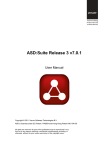
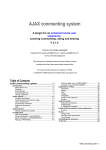
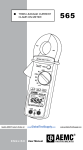
mySensors™
mySensors Wireless
Sensors and Ethernet
Gateway Quick Start Guide
Information to Users
This equipment has been tested and found to comply with the limits for a Class B digital devices, pursuant
to Part 15 of the FCC Rules. These limits are designed to provide reasonable protection against harmful
interference in a residential installation. This equipment generates, uses, and can radiate radio frequency
energy and, if not installed and used in accordance with the instruction manual, may cause harmful interference to radio communications. However, there is no guarantee that interference will not occur in a particular
installation. If this equipment does cause harmful interference to radio or television reception, which can be
determined by turning the equipment off and on, the user is encouraged to try to correct the interference by
one of more of the following measures:
• Reorient or relocate the receiving antenna
• Increase the separation between the equipment and receiver
• Connect the equipment into an outlet on a circuit different from that to which the receiver is connected.
• Consult the dealer or an experienced radio/TV technician for help.
WARNING: Changes or modifications not expressly approved by mySensor could void the user’s authority to operate the
equipment.
RF EXPOSURE WARNING: To satisfy FCC RF exposure requirements for mobile transmitting devices, a separation distance
of 20 cm or more should be maintained between the antenna of this device and persons during device operation. To ensure
compliance, operations at closer than this distance are not recommended. The antenna used for this transmitter must not be
co-located in conjunction with any other antenna or transmitter.
Inside the Box
You should find the following items in the box:
• mySensor™ Wireless Sensors
• mySensor™ Wireless Ethernet Gateway
• Power Supply
• Antenna
• 6 ft. Ethernet Cable
• Mounting Hardware
• Quick Start Guide
• Batteries
mySensors™ Ethernet Gateway Quick Start
• Create a mySensors user account with assigned wireless gateways and sensors.
• Plug an Ethernet cable with internet connectivity into the gateway.
• Plug the power supply into a power outlet then connect to the gateway.
• Once all three lights turn green, your network is ready to bring sensors online.
1. Creating an Account on mySensors™ Online Wireless Sensor
System
- New Users / Create an Account
If this is your first time using the mySensors online system site, you will need to
create a new account. If you have already created an account you can skip to the
“Logging into the Online System” section. The following instructions will guide you
through the account creation process.
1. In a web browser, navigate to http://www.mysensors.se/.
2. Click the “Get Started Here” button.
3. Complete all fields in Account Information section.
Key Fields:
• Time Zone- All data is recorded using Universal Coordinated Time (UTC) also
known as Greenwich Mean Time (GMT). Selecting the time zone will translate
the time stamps in the system to display in your chosen time zone. This can be
updated later if needed.
4. Complete all fields for Primary Contact Information.
Key Fields:
• Cell Phone and Cell Carrier(mySensors) are optional unless you would like to
receive SMS Notifications.
5. Create a new network to hold your gateway and sensors.
Key Fields:
• Network Name - Enter a name for your first network.
• Gateway ID - Numerical serial number located on the bottom of your gateway.
• Gateway Code - 6 digit code on back of sensor, below the serial number.
Note: Additional gateways and sensors can be added to your account in later steps.
6. Once all information has been entered, click the “Create Account” button.
Note: We recommend writing down your username and password to keep in a secure location.
-- Login to mySensors™ Online System
Enter your username and password in the login
fields and click the “Login” button.
PAGE 2
2. Adding Networks, Gateways and Sensors
These steps will allow you to configure additional networks and gateways and sensors
to your account. If you have additional gateways you can either set them up as their own
networks or add them to your existing network.
1. Creating a New Network.
•
•
•
•
•
Choose “Manage” from the main navigation.
Press the button “Create Network”.
Enter a name for the new network.
Enter the Gateway ID and Security Code from the gateway you want to add.
Press the “Create Network” button.
2. Adding Gateways.
•
•
•
•
•
Choose “Manage” from the main navigation.
Select the network you would like to add the gateway to.
Press the button “Network Settings”.
Enter the Gateway ID and Security Code from the gateway you want to add.
Press the “Assign Gateway” button.
3. Adding Sensors.
Choose “Manage” from the main navigation.
Select the network you would like to add the sensor to.
Find the bottom of the section “Add Sensor”.
Enter the Sensor ID and Security Code from the sensor you want to add.
Press the “Assign Sensor” button.
Repeat this process to add more sensors to this network.
_
•
•
•
•
•
•
PAGE 3
3. Using the mySensors™ Ethernet Gateway
- Understanding the Ethernet Gateway Lights
1 2 3
Front of Ethernet Gateway
Light 1 - Indicates the Ethernet cable is plugged in. A green light indicates ready and
working, a red light indicates there is a problem.
Light 2 - Indicates the Ethernet has internet connectivity and can reach the online
monitoring system. A green light indicates ready and working, a red light indicates
there is a problem. A flashing green light indicates network traffic to the internet.
Light 3 - Indicates sensor network activity. A green light indicates ready and working,
a red light indicates there is a problem. A flashing green light indicates radio traffic
from the sensors.
- Ethernet Gateway Controls
Back Panel
Power Plug
Control Button
Ethernet Port
RP SMA Antenna Connector
Using the Control Button:
1) A short press will trigger the gateway to immediately send all stored sensor messages to the online system and download any pending system messages to deliver to
the sensors. (The default heartbeat for the Ethernet gateway is 5 minutes.)
2) Press and hold to reset the gateway to factory settings. This resets the gateway
heartbeat to 5 minutes and changes the heartbeat in the online system as well. You
will need to login to the online system after resetting the gateway to reconfigure the
gateway to your desired settings.
Note: If your gateway powers up with the lights scrolling from left to right, it has entered into boot
loader mode accidentally. Make sure the button is free from obstruction and reboot the gateway by
removing the power plug, waiting for 10 seconds then reinserting the power plug.
PAGE 4
- Configuring The Ethernet Gateway
The Ethernet Gateway collects data from all sensors within range and is preconfigured
to batch deliver the sensor messages to the online system every 5 minutes.
The Ethernet Gateway uses DHCP (Dynamic Host Configuration Protocol) to automatically acquire a network address from the LAN (Local Area Network). In the event that it
needs to have an address manually assigned to it, you can assign an IP address as well
as a gateway mask and default DNS through the online interface. For more information
on configuring the mySensors Ethernet Gateway please view the support
documentation at mySensors support site documentation
Ethernet_Gateway_Configuration.pdf.
Note: This advanced configuration is NOT required in most instances. In the event that it is required,
you will need to initialize it on a network that can reach the online system with the default DHCP settings allowing your configuration settings to be downloaded to the device.
Upon logging into the online system as an administrator, select “Overview” and then
press “View Gateway” then choose the edit tab. From there you can alter the heartbeat of the Ethernet Gateway as well as edit any other configurations available. There
is also a quick link to reset all gateway settings to factory defaults.
4. Bringing mySensor Lite™ Wireless Sensors Online
- Insert Batteries Into Wireless Sensors
Important: Make sure your sensors are at least 3ft. away from Ethernet Gateway.
Peel back the black sticker cover of the battery slot and slide the coin cell battery into
the sensor as shown in fig.1. It will power on within 10-20 seconds. Once online, your
sensor is ready to be deployed. If you wish to change a sensor configuration, change
the parameter in the software. The new parameters will be transmitted to the sensor
on the next heartbeat. If you need a more immediate response from the sensor, power
cycle the sensor by removing, then re-inserting the battery.
Notes:
- If the sensor status indicator does not change, reset
the sensor by removing the battery.
- Wait 60 seconds then re-insert the battery.
- When inserting the battery, make sure to push the
battery all the way back using a paper clip.
- Note the proper orientation of battery in fig.1
Battery
Insertion
fig.1
+
_
Warning: Your sensors ship with a 10 minute heartbeat.
It is recommended that unless you are using the AA battery
solution, you should set the heartbeat to no faster than one hour to preserve battery life. When
changing a sensor’s heartbeat, the new configuration information will be sent to the sensor on it’s
next heartbeat. If you want to update the sensors immediately you can reset them manually.
Manual Sensor Reset Process:
1 - Using the end of a paper clip, push the batteries out of the sensors through the small hole
in the top of the sensor
2 - Change the sensor heartbeat through the online system
3 - Re-insert the batteries into the sensors
PAGE 5
5. Using mySensors™ Online Wireless Sensor System
- TheOnline Interface
When you have logged into the online system this is the default view.
2. Sensor Network “At a Glance”
4. Sensor List
1. Menu System
3. Sensor Health Indicators
1. Menu System
Network Overview
My Account
Notifications
Manage
- Click to return to “Home” view.
- Click to display and edit account information.
- Click setup notifications.
- Click to networks/gateways and sensors.
2. Sensor Network “At a Glance”
Displays the most current readings for every sensor in the selected networkand
last time they checked in.
3. Sensor List
Displays all sensors that are assigned to your sensor network their status
currently. Clicking on the sensor names allows you to view information for that
specific sensor. Clicking the edit button
by a sensor’s name allows you to
change the sensor specific settings such as sensor name and heartbeat (report
interval).
Note: All information stored on the sensor will be downloaded to the sensor on the next sensor
heartbeat (Check-in). If you make a change to any setting, you will need to wait until the sensor
has downloaded the new information before you can edit the configuration settings again.
Sensor status and Icon
Sensor is checking in and within user defined safe parameters.
Sensor has met or exceeded a user defined threshold or triggered event.
Sensor has not checked in (inactivity alert sent).
No sensor readings since shipping
No sensor readings will be recorded (Inactive)
Not Used
Not Used
PAGE 6
4. Sensor Health Indicators and Icons.
Displays the health of the sensors
Signal health for the sensor.
Health of battery.
When you click on a sensor name in the “Sensor List” the right panel will change to this view.
5. Sensor Menu Tabs
8. Date Range Selector
6. Sensor Data Window
7. Sensor Charts
5. Sensor Menu Tabs
Select a tab to change between:
History
Notifications
Chart
Export
Edit
- Displays a history of the selected sensor’s data.
- Allows you to view, add, edit or delete notifications for the sensor.
- Displays a graphical view of the selected sensor’s data.
- Allows you to archive data by exporting as a .csv file.
- Allows you to archive data by exporting as a .csv file.
heartbeat.
The tab highlighted in blue is your current selection.
6. Sensor Data Window (History)
Displays the history of the selected sensor, including: timestamp, signal strength,
battery power and last sensor reading.
7. Sensor Charts
Displays visual charts / graphs for the selected sensor(s) during a specific
time period. Charts and graphs can be printed from this view.
8. Date Range Selector
Allows you to choose the date range for viewable information such as sensor
history, notifications sent, charts and sensor data export.
PAGE 7
- Configuring Sensors
From the Sensor Menu Tabs click on the “Edit” tab to access this area.
The sensor configuration window allows you to set the primary configurations for
each sensor. Within this window you can change the name of the sensor, set the
heartbeat (how often the sensor checks-in with the software - default is every 10
minutes), and change the unit of measurement. When you have finished making
changes, press the “Save” button at the bottom of this section.
Note: Be sure to click the “Save” button anytime you make a change to any of the sensor
parameters. All changes made to the sensor settings will be downloaded to the sensor on the
next sensor heartbeat (check-in). Once a change has been made and “Saved,” you will not
be able to edit that sensor’s configurations again until the sensor has downloaded the new
setting.
- Setting Up Notifications
Automated notifications can be set up to alert you via SMS text or email if a
wireless sensor meets a set threshold or condition. To create a new notification or
edit/delete an existing notification, click on the “Notifications” tab on the Sensor
Menu Tabs. The same thing can be found on the main menu and “Notifications”
Create a New
Notification
View
Notification
Edit an Existing
Notification
PAGE 8
2. Creating a New Notification
Create a New
Notification
Title
Allows you to name your notification.
Class of Notification
There are four notification options available when creating a new notification.
• Application - Application notifications are sensor specific (i.e. water sensor = trigger alert when water present, temp sensor = trigger alert when temp is above 70F,
etc.). If creating an application specific notification, you will need to choose what
sensor type you are creating the alert for. The system will automatically populate a
list of sensor types that are currently being used within the network. The notificatiion
you create will be based on the selected sensor type.
• Inactivity - Set-up “Inactivity” notifications to alert you when your sensors have
stopped communicating with the servers. Failure to set up an “Inactivity” notification will result in no email/SMS txt being sent should your sensors stop communicating with the servers.
• Low battery - Allows users to define a battery power percentage level that will trigger an alert from the system, warning them to replace batteries.
• Advanced Notifications - Allows the user to set notifications based on more advanced rules, such as comparing past data points with the current one to determine
if the notification should be sent.
3. Setting and Editing Notification Settings
People to Notify
Start typing a name into the box and the system will automatically populate the name of
a user within your sensor network. If there are already multiple users on the network, a
drop down list of names will appear. Select the name of the user for the notification. If
the person to be notified does not have an account on the network, you may quick add
them by selecting the “Add Recipient” link and entering in their contact information.
Notification Parameters
This area allows the user to set notification parameters such as the name, the notification message and sensor data conditions that will trigger the notification.
Assigned Devices
Allows you to tell the system which sensors will trigger the notification being created.
When a notifications is sent from the system, it will automatically include the sensor
name and data that caused the notification to be sent.
PAGE 9
- History and Chart Views
Clicking on the “History” or “Chart” tabs within the Sensor Menu Tabs allows you to
view the sensor data history as text or in a graphical chart.
Note: To change the date range of the viewable information, click on the date range box at the top
right of the sensor data window.
PAGE
10
- Exporting Data
Clicking on the “Export” tab within Sensor Menu Tabs allows you to export sensor data
to a comma separated value (.csv) file or send the sensor data to an external web source.
To export sensor data you must first select the date range for the data you want to
export. Once the date range is selected, determine whether you want sensor data from
the selected sensor only, from all sensors in the network or all sensors assigned to the
account. When you are finished, click on “Export Data” at the bottom of this window.
The data will be exported to a comma separated value (.csv) file for use in spreadsheet
software such as Microsoft Excel®. Depending on your browser settings you may be
prompted for a save location. If not, the file will be downloaded to your browser’s default
download directory.
Note: Only the first 2,500 records within the selected date range will be exported.
You can alternately send your sensors’ incoming data to a 3rd party by clicking on the
“Configure data push” link at the bottom of the window. From this area you can pass
data from your wireless sensor network devices to another service in real time. This is
done by coding the data into a url query then sending the data via http get request at the
time data is received. There is an extensive list of parameters that can be passed, as
listed in the viewed window, that allow you to send detailed information about both the
data and the sensor.
For additional information or more detailed instructions on how to use your
mySensors Wireless Sensors or the mySensors Online System, please visit us on
the web at mySensors support site.
Rejoin Telematics AB
Ärlestigen 2
703 48 Örebro
Sweden
+46 19 102618
www.rejoin.com
mySensors are trademark of Rejoin Telematics AB.
All other trademarks are property of their respective owners.
©2013 Rejoin Telematics AB All Rights Reserved.
T108-1389011 (1/13)
PAGE
1111