1
A102-05, Page 2
SECTION 1 - MECHANICAL
1.0
Magnet Disc
1.1
The end of the shaft to be monitored should be square to prevent excessive disc
wobble.
1.2
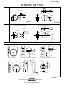
Center drill and tap the shaft end. (Suggested #21 drill and #10-32NF tap). Bolt the
magnet disc to the end of the shaft. Use “Loc-tite” to keep the bolt and disc tight on
the shaft.
(see figure 1A &1C, page 3).
2.0
Magnet Wrap (optional)
2.1
Separate the two halves of the magnet wrap by loosening the cap screws holding
the two halves together.
2.2
Place both halves of the magnet wrap around the shaft. Re-insert and tighten the
cap screws making sure the wrap is square to the shaft.
(see figure 1B & 1D, page 3).
NOTE
There will be a slight gap between the two halves after tightening. This
gap will not affect the generated signal.
3.0
Mounting the Sensor
3.1
Place the sensor so it is centered directly in front of the magnets in the disc
or optional wrap.
(see figure 1A, 1B, 1C & 1D, page 3).
3.2
The gap setting between the sensor and magnet disc should be approximately
1/8” - 7/8”.
CALL TOLL FREE
PCS
TM
PROCESS CONTROL SYSTEMS
800-328-0738
www.maxigard.com
E-mail: [email protected]