1
A102-05, Page 8
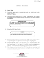
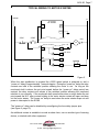
TYPICAL WIRING TO MOTOR STARTER
120VAC
N
A1000
L1
L2
GND
STOP
START
OL’s
M
M
2
1
N.O.
COM
N.O. AUX
3
N.C.
4
5
N.O.
COM
6
N.C.
Figure 6
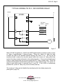
When 120 VAC is applied to L1 and L2 the A1000 speed switch is powered on and a “power
on” delay of approximately 7 seconds begins. During the “power on” delay the relay
contacts are held in the switched position allowing the motor to run. As long as the
monitored shaft is above the set point speed before the “power on” delay period has
expired, the relay contacts will remain in the switched position allowing the monitored
machine to run normally. If the monitored shaft speed slows down or stops below the set
point speed the N.O. relay contact holding the motor starter contact will open and drop out
the motor starter. The “power on” delay is reset when power is removed from L1 and L2.
If the A1000 is powered continuously the “power on” delay only occurs at initial power up
and is not available for later restarts. If continuously powered the start pushbutton will need
to be held closed until the monitored shaft reaches operating speed allowing the motor
starter to seal through the motion switch contact.
The “power on” delay can be disabled by reconfiguring the time delay jumper pins.
(see figure 8, page 10)
An additional contact is available to sound an alarm horn, turn on another type of warning
device, or interlock with other equipment.
CALL TOLL FREE
PCS
TM
PROCESS CONTROL SYSTEMS
800-328-0738
www.maxigard.com
E-mail: [email protected]