1
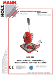
USE AND MAINTENANCE MANUAL EN P 225 YEAR OF MANUFACTURE: ______________ Operation and maintenance manual for P 225 . . . . . . . . . . . . . . . . . . 1 FOREWORD . . . . . . . . . . . . . . . . . . . . . . . . . . . . . . . . . . . . . . . . . . . . . . . . . . . . . . TECHNICAL DATA TABLE . . . . . . . . . . . . . . . . . . . . . . . . . . . . . . . . . . . . . . . . INTRODUCTION . . . . . . . . . . . . . . . . . . . . . . . . . . . . . . . . . . . . . . . . . . . . . . . . . MACHINE SPECIFICATIONS . . . . . . . . . . . . . . . . . . . . . . . . . . . . . . . . . . . . . . 1 1 2 2 CHAPTER 1 --- Functional parts of the machine . . . . . . . . . . . . . . . . . 4 1.1 --- Cutting head . . . . . . . . . . . . . . . . . . . . . . . . . . . . . . . . . . . . . . . . . . . . . . . . . . 1.2 --- Vice . . . . . . . . . . . . . . . . . . . . . . . . . . . . . . . . . . . . . . . . . . . . . . . . . . . . . . . . . 1.3 --- Lubricant/coolant system . . . . . . . . . . . . . . . . . . . . . . . . . . . . . . . . . . . . . . . 4 4 4 CHAPTER 2 --- Safety . . . . . . . . . . . . . . . . . . . . . . . . . . . . . . . . . . . . . . . 5 2.1 --- Intended use of the machine . . . . . . . . . . . . . . . . . . . . . . . . . . . . . . . . . . . . 2.2 --- General recommendations . . . . . . . . . . . . . . . . . . . . . . . . . . . . . . . . . . . . . . 2.3 --- Recommendations for the operator . . . . . . . . . . . . . . . . . . . . . . . . . . . . . . 2.4 --- Machine safety devices . . . . . . . . . . . . . . . . . . . . . . . . . . . . . . . . . . . . . . . . . 2.4.1 --- Reference standards . . . . . . . . . . . . . . . . . . . . . . . . . . . . . . . . . . . . . . . . . . 2.4.2 --- Protection against accidental contact with the blade . . . . . . . . . . . . . . . 2.4.3 --- Electrical equipment . . . . . . . . . . . . . . . . . . . . . . . . . . . . . . . . . . . . . . . . . 2.5 --- Airborne noise from the machine . . . . . . . . . . . . . . . . . . . . . . . . . . . . . . . . 2.5.1 --- Methods of measuring sound level values . . . . . . . . . . . . . . . . . . . . . . . . 2.5.2 --- Noise level values . . . . . . . . . . . . . . . . . . . . . . . . . . . . . . . . . . . . . . . . . . . . 2.6 --- Electromagnetic compatibility . . . . . . . . . . . . . . . . . . . . . . . . . . . . . . . . . . . 2.6.1 --- Emissions . . . . . . . . . . . . . . . . . . . . . . . . . . . . . . . . . . . . . . . . . . . . . . . . . . . 2.6.2 --- Immunity . . . . . . . . . . . . . . . . . . . . . . . . . . . . . . . . . . . . . . . . . . . . . . . . . . . 5 5 5 6 6 7 7 7 7 7 8 8 8 CHAPTER 3 --- Installing the machine . . . . . . . . . . . . . . . . . . . . . . . . . 9 3.1 3.2 3.3 3.5 --------- Unpacking the machine . . . . . . . . . . . . . . . . . . . . . . . . . . . . . . . . . . . . . . . . Check list . . . . . . . . . . . . . . . . . . . . . . . . . . . . . . . . . . . . . . . . . . . . . . . . . . . . Minimum requirements . . . . . . . . . . . . . . . . . . . . . . . . . . . . . . . . . . . . . . . . Connecting electrical power supply . . . . . . . . . . . . . . . . . . . . . . . . . . . . . . . 9 9 9 10 CHAPTER 4 --- Machine operation . . . . . . . . . . . . . . . . . . . . . . . . . . . . 11 4.1 --- Description of controls . . . . . . . . . . . . . . . . . . . . . . . . . . . . . . . . . . . . . . . . . 4.2 --- Manual operating cycle . . . . . . . . . . . . . . . . . . . . . . . . . . . . . . . . . . . . . . . . . 11 12 CHAPTER 5 --- Drawings, exploded diagrams and spare parts . . . . . 13 5.1 --- Diagrams . . . . . . . . . . . . . . . . . . . . . . . . . . . . . . . . . . . . . . . . . . . . . . . . . . . . 5.1.1 --- Electrical diagrams . . . . . . . . . . . . . . . . . . . . . . . . . . . . . . . . . . . . . . . . . . . How to read the wiring diagrams . . . . . . . . . . . . . . . . . . . . . . . . . . . . . . . . . . . . . . 5.2 --- Exploded views . . . . . . . . . . . . . . . . . . . . . . . . . . . . . . . . . . . . . . . . . . . . . . . 5.2.1 --- Head assembly . . . . . . . . . . . . . . . . . . . . . . . . . . . . . . . . . . . . . . . . . . . . . . 5.2.2 --- Vice assembly . . . . . . . . . . . . . . . . . . . . . . . . . . . . . . . . . . . . . . . . . . . . . . . 5.2.3 --- Handgrip . . . . . . . . . . . . . . . . . . . . . . . . . . . . . . . . . . . . . . . . . . . . . . . . . . . 13 13 13 20 20 22 24 CHAPTER 6 --- Adjustments . . . . . . . . . . . . . . . . . . . . . . . . . . . . . . . . . 26 6.1 --- Blade . . . . . . . . . . . . . . . . . . . . . . . . . . . . . . . . . . . . . . . . . . . . . . . . . . . . . . . . 6.1.1 --- Performing angled cuts . . . . . . . . . . . . . . . . . . . . . . . . . . . . . . . . . . . . . . . . 6.2 --- Changing blade . . . . . . . . . . . . . . . . . . . . . . . . . . . . . . . . . . . . . . . . . . . . . . . 26 26 26 CHAPTER 7 --- Maintenance and choice of expendable materials . . 27 7.1 --- Role of the operator responsible for the machine . . . . . . . . . . . . . . . . . . . 7.2 --- Recommendations for maintenance . . . . . . . . . . . . . . . . . . . . . . . . . . . . . . 7.3 --- General machine maintenance . . . . . . . . . . . . . . . . . . . . . . . . . . . . . . . . . . 27 27 27 7.3.1 --- Daily . . . . . . . . . . . . . . . . . . . . . . . . . . . . . . . . . . . . . . . . . . . . . . . . . . . . . . . 7.3.2 --- Weekly . . . . . . . . . . . . . . . . . . . . . . . . . . . . . . . . . . . . . . . . . . . . . . . . . . . . . 7.3.3 --- Monthly . . . . . . . . . . . . . . . . . . . . . . . . . . . . . . . . . . . . . . . . . . . . . . . . . . . . 7.4 --- Maintenance of working units . . . . . . . . . . . . . . . . . . . . . . . . . . . . . . . . . . . 7.4.1 --- Transmission box . . . . . . . . . . . . . . . . . . . . . . . . . . . . . . . . . . . . . . . . . . . . 7.5 --- Expendable materials . . . . . . . . . . . . . . . . . . . . . . . . . . . . . . . . . . . . . . . . . . 7.5.1 --- Transmission box oils . . . . . . . . . . . . . . . . . . . . . . . . . . . . . . . . . . . . . . . . . 7.5.2 --- Oils for the lubricant/coolant fluid . . . . . . . . . . . . . . . . . . . . . . . . . . . . . . 27 27 27 27 27 27 27 27 CHAPTER 8 --- Choice of blades . . . . . . . . . . . . . . . . . . . . . . . . . . . . . . 28 8.1 --- Choice of blade . . . . . . . . . . . . . . . . . . . . . . . . . . . . . . . . . . . . . . . . . . . . . . . 8.1.1 --- Tooth pitch . . . . . . . . . . . . . . . . . . . . . . . . . . . . . . . . . . . . . . . . . . . . . . . . . 8.1.2 --- Cutting and feeding speed . . . . . . . . . . . . . . . . . . . . . . . . . . . . . . . . . . . . 8.1.3 --- Lubricating/cooling fluid . . . . . . . . . . . . . . . . . . . . . . . . . . . . . . . . . . . . . . 8.1.4 --- Blade structure . . . . . . . . . . . . . . . . . . . . . . . . . . . . . . . . . . . . . . . . . . . . . . 8.1.5 --- Types of blade . . . . . . . . . . . . . . . . . . . . . . . . . . . . . . . . . . . . . . . . . . . . . . . 8.1.6 --- Recommended cutting parameter table . . . . . . . . . . . . . . . . . . . . . . . . . . 8.2 --- Classification of steels . . . . . . . . . . . . . . . . . . . . . . . . . . . . . . . . . . . . . . . . . . 8.2.1 --- Steel nomenclature table . . . . . . . . . . . . . . . . . . . . . . . . . . . . . . . . . . . . . . 28 28 28 28 29 29 31 32 32 CHAPTER 9 --- Diagnostics tables . . . . . . . . . . . . . . . . . . . . . . . . . . . . . 33 9.1 --- Diagnostics for blades and cuts . . . . . . . . . . . . . . . . . . . . . . . . . . . . . . . . . . 9.2 --- Troubleshooting . . . . . . . . . . . . . . . . . . . . . . . . . . . . . . . . . . . . . . . . . . . . . . . 33 35 Operation and maintenance manual for P 225 FOREWORD The machine P 225 is a pendulum bench sawing machine designed for cutting metals. Operation is manual: after turning on the electrical power supply to the machine and clamping the workpiece in the vice, the operator starts the blade by pressing the microswitch located on the control lever; he then moves the head downwards in order to cut the material; after completing the cut, the cutting head returns to position ready for a new cutting cycle. TECHNICAL DATA TABLE P 225 U.M. DATA DISC BLADE External blade diameter -- profiles / solid pieces mm 225 Diameter of internal hole mm 32 Blade thickness mm 2 rpm 50 Head spindle motor 2--4 poles std. 2 speed kW 0.8 Maximum installed electrical power kW 0.8 Oil for lubrication/cooling liquid (concentration 5--6 %) capacity kg 0.7 Transmission box oil capacity Lt. 2.5 CUTTING SPEED Standard speed VALUES OF POWER AND CONSUMPTION P 225 1 Presentation INTRODUCTION This working tool has been designed to provide a simple and reliable solution to the needs of DIY enthusiasts and fitters who work with metals and require a practical and versatile machine. The P 225, is a compact, lightweight pendulum sawing machine that can perform cuts angled by 45° to the left; these features make the P 225 a versatile and economical machine. Congratulations on choosing the P 225. This machine will give you many years of trouble--free operation provided you follow the instructions given in this operation and maintenance manual. MACHINE SPECIFICATIONS IDENTIFICATION PLATE: The anodized aluminium identification plate is riveted to the side of the machine. IMPORTANT: every time you contact the Service Centre make sure you quote the model, serial number and year of manufacture given on the plate. The Rock Solid Solution HYD--MECH model air pressure -- data code V 1 PH oil pressure bar -A bar -3 PH -V A DIMENSIONS: a = 640 mm b = 90 mm d c = 370 mm d = 710 mm b weight = 38 kg a c CUTTING CAPACITY FOR PROFILES : Cross--section 0 degrees 45 degrees left 2 Blade diameter 225 65 60 225 55 50 P 225 Presentation CUTTING CAPACITY FOR SOLID PIECES : Cross--section 0 degrees 45 degrees left Blade diameter 225 45 45 225 40 40 Max. opening of cutting vice: 70 mm DISC BLADE: Dimensions: HM 225 x 32 x 2 mm for solid pieces and profiles Cutting speed: standard 50 r.p.m. SPINDLE MOTOR: Spindle motor: single phase 4 poles; 50 Hz; IP 54. Characteristics: Voltage Volt 4 poles 230 Absorption Amp. 5.8 Power kW 0.8 r.p.m. 1.355 Stator winding in enamelled copper class H 200° C; Insulation class F (limit temperature TL=155° C); Example of class F insulation : in air--cooled machines at a room temperature of 40° C (in accordance with CEI 2--3 and IEC 85) the admissible overtemperature is 100° C (where 100° C represents the admissible ∆T). IP 54 protection rating (total protection against contact with live parts and against water sprayed from any direction). Complies with CEI standards, IEC publication 34 of 1 July 1985. P 225 3 CHAPTER 1 - Functional parts of the machine 1.3 -- Lubricant/coolant system In order to gain a good understanding of the machine, which will be described in detail in the chapter ”MACHINE OPERATION”, we will look at its main units and their respective positions. The lubricant/coolant system consists of a membrane pump driven by a cam mechanical system located on the shaft onto which the blade is flanged. 1.1 -- Cutting head The cutting head is the unit that performs the cut and consists of a cast iron section on which the following parts are mounted: the blade, the blade support units, the drive transmission unit and the spindle motor. The cutting head is fixed to the turntable by means of a hinge and travels downwards to perform the cut. The upwards and downward movement of the head is controlled manually by the operator. 1.2 -- Vice The vice is the unit that holds the workpiece steady during cutting; it consists of a vice support on which the slide with the mobile jaw and the fixed jaw is mounted. The vice support is fixed to the upper section of the base. 4 P 225 CHAPTER 2 -- Safety CONNECTIONS The P 225 has been designed and constructed to comply with European standards. It is extremely important that you follow the instructions given in this chapter, as they are essential for correct use of the machine. On the basis of the machine’s power absorption levels given in the ”Machine specifications” tables on page 2, check that the electric and pneumatic power supply lines are able to withstand the machine’s maximum absorption levels and make any necessary changes. EARTHING SYSTEM The earthing system must meet precise specifications as prescribed by the IEC STANDARD 204. 2.1 -- Intended use of the machine OPERATOR POSITION The pendulum disc sawing machine P 225 is intended to be used exclusively for cutting metal profiles. The machine’s specific characteristics make it unsuitable for other types of material or process. Personnel training is the responsibility of the employer, who must inform operators about risks of accident, safety devices, risks related to noise emission and general safety precautions laid down by international directives and legislation of the country in which the machine is used. The operator must be fully aware of the position and operation of all the machine’s controls. The instructions, warnings and general safety precautions described in this manual must be followed completely by the personnel using the machine. In accordance with the MACHINERY DIRECTIVE 98/37/CE EEC and subsequent supplements and amendments 91/368--93/44--93/68, the following definitions are used: The operator using the machine must be in the position shown in the diagram below. 2.3 -- Recommendations for the operator ` ”Danger zone”: any zone within and/or around machinery in which an exposed person is subject to a risk to his health or safety. Always wear adequate safety glasses. ` ”Exposed person”: any person wholly or partially in a danger zone. ` ”Operator”: the person or persons given the task of installing, operating, adjusting, maintaining, cleaning, repairing or transporting machinery. WARNING: The manufacturer is released from all civil and criminal liability if one or more parts or units of the machine are tampered with and/or replaced without due authorisation, or if any accessories, tools and expendable materials are used other than those recommended by the manufacturer, or if the machine is inserted in a complex system or it is used in any way that is different from the intended use. Do not use the machine without the guards in position. Do not place your hands or arms in the cutting zone while the machine is working or the tool is still turning. 2.2 -- General recommendations Do not wear loose--fitting clothing, long sleeves, gloves of the wrong size, bracelets, chains or anything else that might get caught in the machine during operation; tie back long hair. LIGHTING A lack of adequate lighting for the intended type of operation could lead to risks for the safety of personnel. For this reason the user of the machine must ensure that suitable lighting is provided for the working environment in order to eliminate any areas of shadow or irritating glare. (Reference standard ISO 8995--89 ”Lighting in working environments”). Always disconnect the machine from the electrical power supply before carrying out any maintenance work on the machine or changing the blade. This also applies to operations that lie outside the normal use of the machine. P 225 5 Safety Before starting to cut, make sure that the material is adequately supported on both sides of the machine. When operating the saw, wear gloves only for handling material and for adjusting or changing the blade. Carry out only one operation at a time and do not fill your hands with more than one object at the same time. Keep your hands as clean as possible. Work may be carried out on the hydraulic and pneumatic systems only after the pressure inside them has been released. Warning: if the blade seizes while cutting, immediately press the machine’s emergency stop button. If the blade does not free, open the vice slowly, remove the workpiece and check that the blade and the teeth are not broken. If they are, replace the blade. Before carrying out any repair work on the machine, contact the Technical service centre or if necessary its representatives in the country in which the machine is used. The operator must avoid operations that are unsafe or not appropriate for the job being performed (e.g. removing swarf from the machine while cutting). 2.4 -- Machine safety devices Clear the cutting area of tools, implements and all other objects; keep the working area as clean as possible. This operation and maintenance manual is not intended to be solely a guide to using the machine for the purposes of production, but provides instructions to ensure that it is used correctly with a view to the safety of workers. Below is a list of the standards prescribed by the EEC council contained in directives regarding the safety of machinery, safety at the workplace, personal protection and environment protection. These standards have been applied to the P 225. Before starting the cutting operation, make sure that the workpiece is held securely by the vice and that the machine is correctly set up. The following are examples of how different section bars can be locked on our sawing machines. 2.4.1 -- Reference standards SAFETY OF MACHINERY ` EEC directive no. 98/37/CE of 14.06.1989 known as the ”Machinery directive”. ` EEC directives nos. 91/368;93/44;93/68 amending EEC directive no. 98/37/CE regarding the safety of machinery. ` EEC directive no. 73/23 known as the ”Low tension directive”. SAFETY AT THE WORKPLACE ` EEC directives nos. 80/1107; 83/477; 86/188; 88/188; 88/642 relating to the safeguarding of workers against risks deriving from exposure to chemical, physical and biological agents during work. Do not use the machine for cutting workpieces that exceed the capacity stated on the technical sheet. ` EEC directive no. 89/391 and Special EEC directives no. 89/654 and no. 89/655 relating to the improvement of health and safety of workers at work. ` EEC directive no. 90/394 relating to the safeguarding of workers against risks deriving from exposure to carcinogenic agents during work. Do not move the machine while it is cutting. ` EEC directives no. 77/576 and no. 79/640 regarding safety signs at the workplace. INDIVIDUAL PROTECTION Do not use blades with different dimensions from those declared in the machine specifications. ` EEC directives no. 89/656 and no. 89/686 regarding the use of individual protective devices. ENVIRONMENT PROTECTION ` EEC directive no. 75/442 regarding waste disposal. When cutting extremely short workpieces, make sure that they are not dragged behind the rest shoulder as this gives rise to a risk of the blade seizing. 6 ` EEC directive no. 75/439 regarding the disposal of used oil. P 225 Safety 2.4.2 -- Protection against accidental contact with the blade 2.5 -- Airborne noise from the machine Noise causes damage to hearing and is a problem that many countries tackle by laying down specific regulations. In conformity with the regulations established by the Machinery Directive 98/37/CE/EEC, we hereby inform you of the standards prescribing the sound level threshold for machine tools. This chapter provides the values of airborne noise levels generated by the P 225 in the various stages of its operation and the method used for measuring the sound level values. This situation is regulated in ITALY by the D.M.no.277/91 which has adopted the Community Directives 80/1107/EEC, 82/605/EEC, 83/477/EEC, 86/188/EEC, 88/642/EEC. 1 2 2.5.1 -- Methods of measuring sound level values The sound level measurements are carried out using an instrument called an Integrating sound level meter which serves to measure the weighted equivalent continuous sound pressure level at the workplace. The damage caused by noise depends on three factors: level, frequency distribution and duration. The concept of equivalent level Leq combines the three factors so as to provide just one simple parameter. The Leq is based on the equal energy principle and represents the continuous stationary level with the same energy content, expressed in dBA, as the real fluctuating level in the same period of time. This calculation is performed automatically by the integrating sound level meter. Each measurement lasts for 60 seconds to allow the value to stabilise; the value obtained remains on the display to give the operator time to read it. Measurements are made with the equipment held at a distance of about 1 metre from the machine and at a height of 1.60 m from the operator’s workplace platform. Two measurements are made: the first while the machine is performing a manual cut without a workpiece; the second while the material is being cut manually. ¡ Metal blade guard fixed to the cutting head; © mobile blade guard attached to the fixed guard and the machine body to ensure that the blade is covered and that only the part of the blade engaged in cutting is left free, as prescribed by the DPR 547/55 art.108. 2.4.3 -- Electrical equipment In accordance with the Italian standard CEI 60204--1, September 1993, deriving from the European standard EN 60204--1 IEC publication 204--1, 1992: - Accessibility to the electrical panel restricted by screws; - earthing of all parts subject to risk of contact accidentally or during work; - the power supply sectioning device realised with a socket/plug combination in accordance with 5.3.2 sub--section c. 2.5.2 -- Noise level values Identification Machine type Band saw for metal applications Model P 225 Reference standard ISO 3746 Results Description 50x15 mm pipe in FE37 steel Disc blade HSS--DMO5 Ø 225x32x2 Results MEAN SOUND LEVEL (Leq) 101.25 dB (A) Environmental correction (K) 2.78 dB(A) Peak sound power (Lw) 111.82 dB(A) Description 35 mm Ø solid tube in FE37 steel. Disc blade HSS--DMO5 Ø 225x32x2 Results MEAN SOUND LEVEL (Leq) 93.16 dB(A) Environmental correction (K) 2.78 dB(A) Peak sound power (Lw) 102.34 dB(A) Description 20 mm Ø solid tube in FE37 steel. Disc blade HSS--DMO5 Ø 225x32x2 Results MEAN SOUND LEVEL (Leq) 89.67 dB(A) Environmental correction (K) 2.78 dB(A) Peak sound power (Lw) 98.40 dB(A) Test 1 Test 2 Test 3 P 225 7 Safety magnitude as to contaminate the surrounding electromagnetic environment beyond clearly prescribed limits”; 2 “IMMUNITY: the appliance or system must be able to operate correctly even when it is placed in an electromagnetic environment that is contaminated by disturbances of defined magnitude”. The following text contains a list of the applied standards and the results of the electromagnetic compatibility testing of machine model P 225; Test report no. 051200. 2.6 -- Electromagnetic compatibility As from 1 January 1996 all electrical and electronic appliances bearing the CE marking that are sold on the European market must conform to Directive 89/336/EEC and decree law no. 476/92 concerning electromagnetic compatibility, i.e. the compatibility of electrical/electronic devices and systems with the electromagnetic environment in which they are located. The prescriptions regard two specific aspects in particular: 1 “EMISSIONS: during its operation, the appliance or system must not emit spurious electromagnetic signals of such 2.6.1 -- Emissions ` EN 55014--1 (1998) + A2 (1999) Electromagnetic Compatibility -- Requirements for household appliances, electric tools and similar apparatus part 1: Emission -- Product family standard. ` EN 61000 -- 3 -- 2 (1995) + A1/A2 (1998) Electromagnetic compatibility (EMC) -- Part 3: Limits -- Section 2: Limits for harmonic current emissions (equipment input current < 16 A per phase). ` EN 61000 --3 -- 3 (1995) Electromagnetic compatibility (EMC) -- Part 3: Limits -- Section 3: Limitation of voltage fluctuations and flicker in low--voltage supply systems for equipment with rated current < 16 A. CONDUCTED EMISSIONS Port A.C. mains Freq. (MHz) 0.15 --- 0.5 0.5 --- 5 5 --- 30 Q---peak limit (dBuV) 66 --- 56 (decreasing linearly with the logarithm of the frequency) 56 60 Limit average (dBuV) 56 --- 46 (decreasing linearly with the logarithm of the frequency) 46 50 Result Pass CONDUCTED EMISSIONS --- ANALYSIS OF DISCONTINUOUS DISTURBANCE Port A.C. mains Result Not applicable HARMONIC CURRENTS EMISSIONS Port A.C. mains Port A.C. mains Limit (class) A Result Pass FLICKER AND VOLTAGE VARIATIONS Flicker limit pst = 1 plt: not applicable Result Pass Voltage variation limit dc = 3% d max = 4 % d(t) = 200 ms Result Pass 2.6.2 -- Immunity ` EN 55014 -- 2 (1998) Electromagnetic compatibility -Requirements for Household appliances, electric tools and similar apparatus Part 2: Immunity -- Product family standard. IMMUNITY TESTS EUT classification Category I (Apparatus containing no electronic control circuitry) 8 Result Pass (Category 1 apparatus are deemed to fulfil the immunity requirements without testing) P 225 CHAPTER 3 - Installing the machine Before installing the machine, remove the packaging, taking care not to cut electric cables or hydraulic hoses and using pliers, a hammer and a cutter as required. To place the machine in its working position, follow the instructions given in paragraph 3.4. The working position must be chosen taking into consideration the machine dimensions and the space required to allow the operator to perform all necessary manoeuvres to ensure his safety. 3.1 -- Unpacking the machine Hyd--Mech uses packaging that is appropriate for protecting the machine from damage during transport right up until the time it is delivered to the customer. The type of packaging used for the machine depends on the dimensions, weight and destination, so the customer will receive the machine in one of the two following ways: -- package including pallet, straps and cardboard box with lid. 3.2 -- Check list Before beginning to install the machine, check the standard and optional accessories provided with the machine. The standard version of the P 225 1 SPEED sawing machine is supplied complete with: ` pedestal with tank for coolant; ` membrane pump for lubrication and cooling of blade; ` IP 55 head control lever; ` mobile guard to cover part of blade not engaged in cutting; ` rotating head with screw locking facility to perform angled cuts; ` possibility of performing cuts from 0_ to 45° to the left; ` 1 speed single--phase electric motor; ` bag of accessories. The bag of accessories is enclosed in the machine before packaging and contains the following accessories: ` 4, 5, 6, 10 mm Allen keys; ` rod for measured cuts; ` this operation and maintenance manual; OPTIONAL ACCESSORIES AVAILABLE ON REQUEST: ` HSS DMo5/M2 D.225x32x2 circular blade for cutting solid bars and profiles; ` 5 l can of emulsible oil. -- package with pallet, cardboard boxes (for more than one machine) and wooden crate. 3.3 -- Minimum requirements The following are the minimum environmental requirements needed to ensure correct operation of the machine: ----- mains voltage / frequency: see values given on the data plate; room temperature: from -- 10 to + 50 °C; relative humidity: no higher than 90%; room lighting: no lower than 500 Lux. WARNING ! Although the machine is protected against voltage variations, good operation can only be ensured by stable voltage, which should not vary by more than 10%. In either case, lift the machine using a fork lift truck, inserting the forks at the points marked by the arrows and following the instructions given on the box. WARNING! Do not handle the packaged machine by harnessing with a sling. NO P 225 9 Installing the machine 4 -- Check that the motor turns in the correct direction. To do this, proceed as follows: 3.5 -- Connecting electrical power supply a) press the jog button on the head control lever; Before connecting the machine to the electrical power supply, check that the power socket is not connected in series with other machines. This is essential in order to ensure good operation of the machine. To connect the machine to the mains electric power supply proceed as follows: 1 -- connect the machine’s power cable to a plug which is suitable for the socket you have decided to use, EN 60204--1 para. 5.3.2. b) if the operations have been performed successfully, the blade motor will start up and the blade will start to turn. 2 -- Insert the plug in the socket, checking that the mains voltage corresponds to the voltage the machine was designed for. VOLT ? VOLT ? 3 -- Press the red button on the blade motor box. The button lights up and the machine is now on STAND--BY. Check that the blade turns in the right direction as shown in the diagram. The saw is now ready to start work. See Chapter 4 for a detailed description of the operation of the machine. 10 P 225 CHAPTER 4 - Machine operation In this chapter we will look at all the functions of the machine, starting with a description of the control panel buttons and components. 4.1 -- Description of controls The drawing below shows the controls of the P 225; each numbered arrow corresponds to a description given in the following text. 1 2 Head control lever. 1 -- ON/OFF SWITCH 2 -- HEAD CONTROL LEVER MICROSWITCH The microswitch controlling the blade motor is located on the head control lever knob. Operating lever Microswitch Press this button to turn on the power supply to the machine. The switch lights up when it is in the ON position, letting the operator know that the machine is on stand--by. Providing no emergency condition has occurred, this is enabled when the machine is turned on. The voltage is 24 Volt in accordance with applicable legislation. The microswitch is mounted in an enclosure (blue knob) isolated from external agents, such as dust and humidity, with a protection rating of IP 55. P 225 11 Descrizione del funzionamento della macchina 6) The motor starts, causing the blade to turn. At the same time the lubricant/coolant pump starts up. 4.2 -- Manual operating cycle Sequence of operations to be performed when making any cut: 1) Turn the machine’s power supply on by pressing the ON/OFF switch. 2) Place the material inside the vice and calculate the length of the cuts (using the rod for measured cuts). 7) When the cut is completed, move the head back upwards. 3) Clamp the workpiece in the cutting vice. 4) Make sure the workpiece is securely clamped in the vice by trying to move it manually. 8) Free the workpiece from the vice by turning the handwheel. The machine is now ready for a new operation. 5) Grip the head control lever and start the blade turning by pressing the microswitch on the handgrip; the head is guided manually by the operator at the desired speed. 12 P 225 CHAPTER 5 -- Drawings, exploded diagrams and spare parts This chapter provides the functional and exploded diagrams for the P 225. This documentation will help you locate the parts that make up the machine so as to allow you perform repair and/or maintenance work; it will also enable you to indicate the spare part you require without any risk of misunderstanding by defining it correctly with its position number and code. 5.1 -- Diagrams 5.1.1 -- Electrical diagrams How to read the wiring diagrams With the introduction of the new standardised wiring diagrams, the following gives an illustration of the way in which they have been drawn up. Each sheet of the project contains a box which gives the following information: The numbers indicate the columns into which the entire drawing is divided MARIO ROSSI Indications of the model of machine Indications of the date production started MARIO ROSSI Indication of the page number Identification of the designer Identification of the Reference Standard P 225 13 Drawings, exploded diagrams and spare parts Each component in the wiring diagram is identified by a unique alphanumeric identification code, in compliance with regulations: The wire is identified by the code --W4 This symbol identifies the wire with its relative number and colour MARIO ROSSI These symbols, known as potentials, are used to provide page references: the first number indicates the page to be referred to, the second number, after the dot, identifies the column on that page; example /11.8 indicates that the wire continues on page no. 11 in column 8 The motor is identified by the code --M1 The pages following the wiring diagrams contain the following lists: 1. components list (list of all components) and terminals list (list of all the terminals) with the following information: H H H H H in--house article code; identification code; reference, no. of the page and column on which it can be found; description; manufacturer ART. COD. ID PRES.REF DESCRIPTION MANUFACTURER 022.2151 --B1 /5.2 Strain gauge Deltatec 14 P 225 Drawings, exploded diagrams and spare parts wires list (list of all wires) with the following information: 2. H H H H H H H CODE 022.0141 in--house article code; identification code; description section of wire (mm2); colour of wire; start: indicates the component (identification code and contact number) at which the wire starts; end: indicates the component (identification code and contact number) at which the wire ends; e.g. CABLE DESCRIPTION --W7 RESET+EMERGENCY SECTION 0.50 NO. 317 COLOUR WHITE START --S3 4 END --K10 14 In this example, wire no. 317 white, identified as ---W7, starts from contact no. 4 on component ---S3, and ends at contact no. 14 on component ---K10. Enclosed below is Appendix D2 to European Standard EN 60204---1 D2---Letter codes used to designate the type of component LETTER TYPE OF COMPONENT EXAMPLES Complex units Laser Maser Regulator B Transducers converting a non electrical signal to an electrical signal and vice versa Transistor amplifier IC amplifier Magnetic amplifier Valve amplifier Printed circuit board Drawer Rack C Capacitors A IDENTIFICATION OF THE APPLIANCE A AD AJ AM AV AP AT AR C D Binary operators, timing devices, storage devices Digital integrated circuits and devices: Delay line Bistable element Monostable element Recorder Magnetic memory Tape or disk recorder E Various materials Devices not specified in this table E Lightning protectors Arrestors F D FA F Protective Devices Instant action current threshold protector Delayed action current threshold protector Instant and delayed action current threshold protector Fuse Voltage threshold protector FR FS FU FV P 225 15 Drawings, exploded diagrams and spare parts LETTER TYPE OF COMPONENT EXAMPLES Rotating generators Crystal oscillators G H Generators, feeders Signaling Devices Accumulator battery Rotating or static frequency converter Power feeder Buzzer Optical signal, indicator light device IDENTIFICATION OF THE APPLIANCE G GB GF GS HA HL J K Relays, Contactors Instant all or nothing relays or instant contactors Bistable relays or interdependent contactors (All or nothing contactors with mechanical contact or permanent magnet etc.) Contactors Polarised relays Reed relays All or nothing timed relays (timers) Inductor Stop coil Reactor KA KL KM KP KR KT L Inductors, reactors L M Motors N Analogue intgrated circuits Operational amplifiers Hybrid analog/digital appliances N P Measurement equipment, test devices Indicator, recorder and integrator measurement devices Signal generators P Q Power circuit switching appliances Automatic switch Engine saver switch Knife switch R Resistors Fixed or variable resistor (rheostat) Command or control devices Selector or switch Button (including electronic proximity switch) Numerical all or nothing sensors (single step) of mechanical and electronic type: -- Liquid level sensor --Pressure sensor Position sensor (including proximity) --Rotation sensor --Temperature probe M QF QM QS R SA S 16 P 225 SB SL SP SQ SR ST Drawings, exploded diagrams and spare parts LETTER T U V W X Y Z TYPE OF COMPONENT EXAMPLES IDENTIFICATION OF THE APPLIANCE TA Transformers Current transformer Control circuit supply transformer Power transformer Magnetic stabiliser Voltage transformer Modulators, converters Discriminator Demodulator Frequency converter Coder Converter Inverter Telegraphic repeater U Electronic pipes, semiconductors Electronic pipe Gas discharge pipe Diode Transistor Thyristor V Transmission lines, wave guides, antennas Conductor Cable Bar Wave guide Wave guide directional coupler Dipole Parabolic antenna W Terminals, sockets, plugs Connector bar Test plug Plug Socket Terminal connector band XB XJ XP XS XT Electrically operated mechanical appliances Electromagnet Electromagnetic brake Electromagnetic clutch Magnetic table spindle Electromagnetic valve Transformers, impedence Line equalizer adapters, equalizers, band limi- Compresser ters Crystal filter P 225 TC TM TS TV YA YB YC YH YV Z 17 Drawings, exploded diagrams and spare parts STANDARDISED ELECTRICAL DIAGRAMS 18 P 225 Drawings, exploded diagrams and spare parts CABLE LIST CODE CABLE 022,1901 022,1901 022,1901 022.0139 022.0139 --W1 --W1 --W1 --W52 --W52 TYPE DESCRIPTION AWM Power Supply AWM Power Supply AWM Power Supply AWM Microswitch AWM Microswitch COLOR BROWN BLUE YELLOW/GREEN BLUE BROWN LENGTH 2500mm 2500mm 2500mm 1000mm 1000mm START END --S50:3 --X1 --X1 --S50:3 PE --S15:3 --S15:4 COMPONENT LIST CODE 019,1722 022,0515 034,1221 010,0928 025,0691 DESCRIPTION TYPE BLADE MOTOR MICRO--SWITCH KNOB SPRING KNOB SEAL HP 2/2,5 2/4P 230 Vac 60 Hz SWITCH KNOB SPRING SEAL P 225 ID, REF. --M1 --S15 --S15 --S15 --S15 /1.5 /2.5 /2.5 /2.5 /2.5 19 Diagrams, exploded views and spare parts 5.2 -- Exploded views This part of the manual contains the exploded views of the P 225 which will assist in gaining a thorough knowledge of the machine. 5.2.1 -- Head assembly 20 P 225 Diagrams, exploded views and spare parts PARTS Code 001.0359 005.2151 007.1056 007.1061 010.1601 010.1605 010.1905 010.7010 010.7103 010.7204 010.7221 010.7242 010.7601 010.7602 010.7603 010.7604 010.7606 010.7730 010.7764 010.7831 010.7850 010.7860 010.7868 010.7870 010.7940 010.7963 011.0007 016.0224 016.0303 016.0350 016.0435 019.1706 019.3004 025.0115 025.0116 025.0203 025.0237 025.0628 025.0813 028.0005 034.0503 034.0900 043.0269 090.0271 Description TEMP. HEAD BLADE COVER 0 225 BLADE FLANGE FRONT TAP PUMP ECCENTRIC BUSHING WY GUARD SCREW LEVER WILLY N.S. 0 45 SEEGER RING 5 X 5 X 30 KEY M8 SCREW NUT M16 LOW SCREW NUT M17 LOW SELF--LOCKING SCREW NUT 0 4 WASHER 0 5 WASHER 0 6 WASHER 0 8 WASHER 0 12 WASHER CONIC PIN DIAM. 8 X 35 ELASTIC PIN DIAM. 6 X 20 5 X 12 BUTON SCREW TCEI 4 X 8 SCREW TCEI 5 X 15 SCREW TCEI 6 X 12 SCREW TCEI 6 X 16 SCREW TCEI 12 X 30 SCREW TE 8 X 25 SCREW BLADE SHAFT GUARD BRACKET PUMP SUPPORT PUMP SMALL PLATE PUMP GUARD HP 2/2,5 2/4P V.380 HP 1 V.220 1--PH. 4PS6B4 W. FLANGE WORM SCREW BRONZE GEAR SEAL 35X25X7 O RING 2118 MOTOR GASKET ROLLER BUSHING INA HK 1512 LUBRICATING PUMP BLADE GUARD SLNT 38 3/8 OIL LEVEL CAP CL 1500 6/4 1/8 STRAIGHT JOINT COMPLETE MEP HANDLE UofM NR NR NR NR NR NR NR NR NR NR NR NR NR NR NR NR NR NR NR NR NR NR NR NR NR NR NR NR NR NR NR NR NR NR NR NR NR NR NR NR NR NR NR NR P 225 Quantity 1,000 1,000 1,000 1,000 1,000 1,000 1,000 1,000 1,000 2,000 1,000 1,000 2,000 4,000 1,000 4,000 1,000 1,000 1,000 2,000 2,000 3,000 2,000 1,000 1,000 6,000 1,000 1,000 1,000 1,000 1,000 1,000 1,000 1,000 1,000 3,000 1,000 1,000 1,000 1,000 1,000 1,000 1,000 1,000 21 Diagrams, exploded views and spare parts 5.2.2 -- Vice assembly 22 P 225 Diagrams, exploded views and spare parts Parts Code 090.0261 001.0353 001.0355 001.0357 007.1055 007.1058 007.1059 007.1060 010.0203 010.0904 010.1201 010.1606 010.7008 010.7427 010.7467 010.7602 010.7603 010.7605 010.7767 010.7771 010.7859 010.7868 010.7893 010.7979 016.0178 016.0202 016.0500 028.0150 034.0202 034.1110 Description COMPLETE HANDLE ROTATING TABLE VICE JAW FIXED PLATFORM WITH VICE PIN ROD STOP SPACER CUT TO MEASURE STOP PIN VICE SCREW 205X20 HEAD RETURN SPRING SCREWS AND BOLTS ROTATING TABLE FIX PLATE 0 25 SEEGER RING 8 X 12 CYLIND.POINT VCE GRUB SCREW 6 X 12 FLAT POINT VCE GRUB SCREW 0 5 WASHER 0 6 WASHER 0 10 WASHER ELASTIC PIN DIAM. 6 X 35 ELASTIC PIN DIAM. 8 X 20 TCEI 5 X 12 SCREW TCEI 6 X 12 SCREW TCEI 8 X 20 SCREW TE 10 X 50 SCREW VICE WATER COLLECTOR TANK GUARD FIXED SUPPORT VICE COVER PLASTIC HOSE 04--6 SMALL VICE HANDWHEEL O 30 M6 X 10 HANDWHEEL P 225 UofM NR NR NR NR NR NR NR NR NR NR NR NR NR NR NR NR NR NR NR NR NR NR NR NR NR NR NR KG NR NR Quantity 1,000 1,000 1,000 1,000 1,000 1,000 1,000 1,000 1,000 1,000 1,000 1,000 2,000 1,000 1,000 2,000 2,000 1,000 1,000 1,000 2,000 2,000 4,000 1,000 1,000 1,000 1,000 0,030 1,000 2,000 23 Diagrams, exploded views and spare parts 5.2.3 -- Handgrip 24 P 225 Diagrams, exploded views and spare parts Parts Code 010.0928 010.7409 010.7700 010.7800 022.0515 025.0691 034.1221 Description MEP HANDLE SPRING 8 X 10 CYLIND.POINT VCE GRUB SCREW CYLINDRICAL PIN DIAM. 4 X 24 2,9 X 15 SELF--THREADING SCREW MICROSWITCH V--21--1C6 GASKETS FOR MEP HANDLE MEP HANDLE P 225 UofM NR NR NR NR NR NR NR Quantity 1,000 1,000 1,000 3,000 1,000 1,000 1,000 25 CHAPTER 6 - Adjustments This chapter provides the instructions to follow when adjusting the mechanical systems of the P 225 in order to use the machine correctly. These instructions allow you to customise your machine and keep operating times down to a minimum. 6.1 -- Blade The HSS cutting discs can be used for any type of cut as they combine extremely high toughness and elasticity obtained by means of a number of tempering treatments, and also offer good cutting resistance. The discs are made of a single piece of tungsten molybdenum steel with a hardness of about 641 HRC. These blades ensure that the cut surfaces have a good finish. -- the machine is now ready for performing cuts angled by 30° to the left. 6.1.1 -- Performing angled cuts The P 225 can perform cuts angled at 45_ to the left. The following operation is necessary to perform a cut angled by 30_. -- Free the turntable by means of the locking screw locating between the vice and the motor support on the turntable itself; 6.2 -- Changing blade -- with the turntable free, turn the machine body to the desired angle (30_), reading off the position on the angle scale located on the bottom section of the turntable. -- Once you have reached the desired angle, secure the machine body by tightening the locking screw; As we have already seen, this machine uses various types of blade depending on the material that has to be cut. However the following operations are the same for the various types of blade and also apply in the event of wear or breakage of the tool. In order to replace, proceed as follows: -- turn off the power supply to the machine; -- free the mobile blade guard by removing it from the eccentric rod (1); -- move the mobile guard upwards (2); -- loosen the blade locking nut using a 10 mm Allen key; -- to undo the blade locking nut, turn it in the direction of disc rotation; -- remove the blade which needs to be replaced (because of wear or for other reasons) and insert the new blade, repeating the above operations in reverse order. The above procedures are exactly the same when the tool has to be replaced because it is worn or broken. Do not perform the above operations without first turning off the electrical power supply to the machine! 26 P 225 CHAPTER 7 -- Maintenance and choice of expendable materials -- The P 225 is a robust machine that ensures a good lifetime. It does not require any special maintenance although, like all machine tools, it is liable to deteriorate with time, especially if it is badly used and not serviced correctly. This chapter therefore serves as a reminder to users who wish to keep their machine in good working order and thus ensure that it provides satisfactory operation for as long as possible. -- check the oil level in the transmission box; if necessary fill up via the plug; check the sliding movement of the vice; if it is not precise and shows transversal play, adjust. 7.3.3 -- Monthly This section lists the monthly maintenance procedures to be carried out on the machine: -- check that the machine performs cuts perpendicular to the work table; if not, contact our service centre; -- check that the blade is perpendicular to the workpiece rest shoulder; if adjustment is required, contact our service centre; -- clean the water tank and the lubrication pump filter thoroughly. 7.1 -- Role of the operator responsible for the machine The person responsible for the operation and maintenance of the machine must follow these instructions in order to guarantee their safety and that of others and to ensure satisfactory operation of the machine: - use the safety devices correctly and comply with the prescribed safety standards when working with the machine and ensure that other operators do so; ensure that the safety devices are correctly positioned and operative and that the individual safety standards are complied with. - make sure that the machine performs the working cycle correctly so as to ensure maximum productivity, checking: -- that the main machine parts operate correctly; -- that the blade is sharp and the flow of cooling liquid is correct; -- that the optimal working parameters for the type of material are complied with. - ensure that cutting quality is satisfactory and that the final product does not show any machining defects. 7.4 -- Maintenance of working units The person responsible for carrying out maintenance on the P 225 must give particular attention to working units such as the transmission box. 7.4.1 -- Transmission box Transmission box maintenance: -- after the first 100 hours of work, empty the transmission box via the discharge plug on the bottom front section of the unit and replace all the oil. If impurities can be observed in the oil, take off the lid and clean inside thoroughly. Use washing oil to do this; avoid drying with cotton or stringy rags. Fill the transmission box with oil; -- replace the oil subsequently after every 2000 hours of work. 7.2 -- Recommendations for maintenance 7.5 -- Expendable materials - All routine and special maintenance operations must be carried out with the plug disconnected from the power supply. It is essential to use oils specifically designed for the lubricant/ coolant circuit. Below is given a list of oils that are suitable for this circuit. - To ensure perfect operation only Hyd--Mech. original spare parts must be used. - When maintenance work is finished, make sure that the replaced parts and any tools used have been removed from the machine before starting it up again. 7.5.1 -- Transmission box oils - Any operations other than those described in the instructions for use and maintenance of the machine may be hazardous for the operator. The machine is supplied with AGIP BLASIA 460 type oil, ISO and UNI symbol CC 460; however the following is a list of suitable oils that have equivalent characteristics: - It is therefore essential to read and observe all the instructions for the use and maintenance of this machine and any instructions regarding the product itself. API DT 460 -- CASTROL Alpha SP 460 -- ARAL Degol BG 460 ARCO PENNANT NL 460 -- BP Energol GR/XP 460 -- ELF Reductelf SP 460 -- ESSO Spartan EP 460 Transmission box: -- transmission box capacity 7.3 -- General machine maintenance 0.7 kg 7.5.2 -- Oils for the lubricant/coolant fluid 7.3.1 -- Daily The type of oil used for the machine’s lubricant/coolant fluid is CASTROL Syntolin TFX. In the absence of any specific legislative requirements, Hyd--Mech has chosen this product as it is the one that provides the best quality/price ratio. In any case the following is a list of suitable oils that have equivalent characteristics: This section lists the daily maintenance procedures to be carried out on the machine: -- remove all swarf from the machine (using compressed air and preferably thread--free rags); -- top up with lubricant/cooling liquid to the required level; -- check the blade for wear and if necessary replace. AGIP NB 200 -- SHELL Lutem TT -- IP Utens Fluid--F Cooling fluid tank: -- tank capacity -- Oil concentration 7.3.2 -- Weekly 2.5 Lt. 5--6 % This section lists the weekly maintenance procedures to be carried out on the machine: -- clean the machine of all swarf; -- clean the vice and lubricate all the joints and sliding surfaces, preferably using good quality oil; P 225 27 CHAPTER 8 -- Choice of blades A larger pitch should be chosen when the cross--section at any given point exceeds the average cross--section given above as a result of the shape of the piece to be cut. When using the P 225 pendulum saw it is important to select the correct type of blade for the material to be cut. This chapter explains the limitations and specific applications of the different types of blades. Type of swarf: A -- Very fine or pulverised swarf indicates an excessively low feeding speed and/or cutting pressure. 8.1 -- Choice of blade The different types of blades that can be used on the P 225 must satisfy the following general requirements: - FINE TOOTH PITCH -- for thin walled materials such as steel plate, tubes and profiles; - COARSE TOOTH PITCH -- for large cross--sections; -- for soft materials (aluminium alloys and soft alloys in general); B -- Thick and/or blue swarf indicates that the blade is overloaded. 8.1.1 -- Tooth pitch The choice of the most suitable tooth pitch depends on a number of factors: a) the size of the section; b) the hardness of the material; c) the wall thickness. Solid sections require discs with a coarse tooth pitch, whereas small cross--sections need blades with finer teeth. This is because when walls of small cross--section (1 7 mm) profiles are cut, it is important that the number of teeth actually making the cut is not too small, otherwise the effect obtained will be one of tearing rather than of swarf removal, leading to a large increase in shearing stress. On the other hand, when cutting thick materials or solid sections using a blade with an excessively fine tooth pitch, the swarf collects as a spiral inside the gullet, and since fine tooth pitches have small gullets, the accumulated swarf will exceed the gullet capacity and press against the walls of the workpieces, resulting in poor cutting (same situation with soft materials), greater shearing stress and hence breakage of the blade. C -- Long, spiral swarf indicates that cutting conditions are ideal. 8.1.2 -- Cutting and feeding speed Choice of tooth pitch T as a function of cross--section to be cut for steel solid pieces and profiles S S sp Pitch T 4 S and sp in mm 10 sp=0.5 6 30 sp=1.5 4--5 50 8 50 sp=2.5 5--6 70 10 70 sp=3.5 6--7 90 130 12 16 90 sp=4.5 130 sp=6.5 7--8 8 S in mm Pitch T 10 30 The cutting speed in m/min and the feeding speed in cm2/min are limited by the amount of heat generated near the points of the teeth. If the feeding speed is too high, the cut will not be straight in either the vertical or the horizontal plane. As we have already seen, the cutting speed depends on the resistance (kg/mm2) and hardness (HRC) of the material and the dimensions of the thickest sections. The feeding speed depends on the cross--section of the material. This means that large cross--section solid or thick--walled materials (s > 5 mm) can have a high feeding speed provided there is sufficient swarf removal by the blade; thin--walled materials, such as thin pipes or profiles, must be cut with a low and above all constant feeding speed. A new blade requires a wearing--in period, during which time a feeding speed of about half normal speed should be used. 3 8.1.3 -- Lubricating/cooling fluid The lubricating/cooling fluid must ensure that the blade teeth and material in the cutting area do not overheat. Furthermore the fluid must be supplied with a sufficient quantity and pressure to remove the swarf from the cutting area. It must be an excellent lubricant to prevent abrasion of the teeth and welding of the swarf to the teeth (seizing). KEY: s = diameter or width of the solid piece to be cut in mm sp = thickness of the wall to be cut in mm T = tooth pitch in mm 28 P 225 Choice of blades 8.1.4 -- Blade structure The most widely used disc blades for sawing machines are made of a single piece of HSS--DMo5/M2 characterised by a high level of toughness and good cutting resistance. For non--ferrous materials, on the other hand, it is common to use circular blades with a brazed hard metal HM cutting edge, which have shown excellent wear resistance but low resistance to impact, which is in any case a minor problem with non--ferrous materials. CHEMICAL COMPOSITION : C TYPE OF BLADE HSS- DMo5/M2 Cr 0.85 4.15 W Mo V Co 6.37 5.00 1.92 HRC Coarse toothing with roughing tooth and finishing tooth. Used on saws with pitch greater than or equal to 5 mm for cutting ferrous and non--ferrous materials with solid or solid--profiled sections. 64+/--1 KEY: ”BW” TYPE SHARPENING DIN 1838--UNI 4014 C = Carbon Co = Cobalt Cr = Chromium Mo = Molybdenum W = Tungsten V = Vanadium The numbers in the columns indicate the % of the element present in the steel. Coarse toothing with teeth alternately raked to the right and to the left. 8.1.5 -- Types of blade The blades fitted on the P 225 have dimensions 225x32x2 and are made of HSS DMo5 since the machine is to be used for cutting ferrous materials. In addition to the size and pitch of the teeth, however, the blades also have different geometric characteristics in accordance with their specific use: - tooth sharpening, which in this case may be BW with an alternate raked tooth or C with a roughing tooth raked on both sides and a non--raked finishing tooth. - tooth pitch, the distance between the crest of one tooth and the crest of the next tooth (tooth pitch = T). Toothing generally used on sawing machines for cutting ferrous materials and alloys with tubular and profiled sections. The P 225 uses 225x2x32 blades made of HSS DMo5 and with C type sharpening teeth for hollow sections. For solid sections, on the other hand, it uses blades of the same dimensions but with a different tooth pitch, as shown in the table below. Shape of teeth: ”C” TYPE SHARPENING (HZ) Coarse toothing with roughing tooth raked on both sides and non--raked finishing tooth. The roughing tooth is about 0.3 mm higher. Table for choosing blades for the machine P 225; other blade characteristics are: dimensions -- internal hole 32, distance between fixing holes 63; tooth shape type C. Hollow profiles with thickness from 1 to 5 mm Hollow profiles with thickness from 5 to 10 mm Solid sections with dimensions that do not exceed the cutting capacity P 225 225 D. T Z 225 4 180 D. T Z D. T Z 225 5 140 225 6 120 P 225 29 Choice of blades This table can be used to facilitate the choice of toothing since it takes into account both the size of the material to be cut and the diameter of the blade. SOLID SECTIONS D. 200 S 10 30 t z 5 130 6 100 t z 6 100 8 80 50 225 250 275 t z 5 140 6 120 t z 6 120 8 80 t z 5 160 6 128 t z 6 128 8 100 t z 5 180 6 140 t z 6 140 8 110 8 90 10 70 8 100 10 80 8 110 10 90 10 90 12 70 70 90 300 315 t z t z t z t z 6 160 8 120 10 90 7 140 8 120 8 120 12 80 14 70 8 120 10 90 12 80 110 S 350 370 400 425 t z t z t z t z t z t z t z t z 10 100 10 100 12 80 9 120 11 100 10 110 12 90 10 110 11 100 11 100 12 90 10 120 12 100 10 130 12 80 14 70 12 90 14 80 12 90 12 100 14 90 12 80 14 70 12 90 14 80 12 90 14 80 14 80 12 100 14 80 16 70 14 80 16 70 6 180 7 160 5 220 7 160 130 450 500 t z t z 12 110 10 140 12 110 14 94 14 90 12 110 14 90 14 90 16 80 16 80 7 160 8 140 6 200 7 160 8 140 7 180 8 140 9 120 9 120 9 120 8 160 9 140 9 140 9 140 150 t z t z 12 120 10 150 12 130 12 120 14 100 12 130 14 110 14 94 12 120 14 100 12 130 14 110 14 94 14 94 16 84 16 84 14 100 14 100 16 90 16 90 14 110 14 110 16 100 16 100 7 180 6 220 7 190 6 230 7 200 6 260 7 220 8 160 7 190 8 160 7 200 8 180 7 220 8 200 8 160 9 150 9 150 9 150 8 180 9 160 9 160 9 160 8 200 9 170 9 170 9 170 D 10 S HOLLOW S=0.005xD SECTIONS D 30 30 50 70 90 110 3 200 4 160 3 200 5 130 3 220 4 180 3 220 5 140 3 250 4 200 3 250 5 160 3 280 4 220 3 280 5 180 4 220 5 180 4 240 5 200 5 140 6 120 5 160 6 128 5 180 6 140 6 140 8 110 5 180 6 160 6 160 8 120 5 200 6 160 6 160 7 140 5 200 6 180 10 100 7 140 8 120 7 160 8 140 8 120 10 100 8 140 9 120 9 120 8 120 130 150 P 225 10 110 10 110 10 110 10 120 10 120 10 130 10 130 10 140 10 140 10 150 10 150 Choice of blades 8.1.6 -- Recommended cutting parameter table α γ RECOMMENDED CUTTING PARAMETERS CUTTING ANGLES T mm Vt m/min. Av mm/min. T mm Vt m/min. Av mm/min. T mm Vt m/min. Av mm/min. T mm Vt m/min. Av mm/min. T mm Vt m/min. Av mm/min. T mm Vt m/min. Av mm/min. T mm Vt m/min. Mild steel 30 18 100 35 16 110 40 14 130 40 12 140 45 10 150 45 7 160 50 5 8 20 R = 350--500 N/mm2 90 R = 500--700 N/mm2 15 16 90 20 16 100 20 14 110 25 12 110 25 9 120 30 6 130 30 4 8 18 Medium steel 80 R = 750--950N/mm2 12 16 70 14 16 80 15 14 50 17 11 100 18 8 110 20 6 110 20 4 8 15 Hard steel 60 12 14 45 13 14 45 13 12 50 14 9 50 14 6 60 15 4 60 15 3 6 12 Super hard steel 40 7 12 25 7 10 25 8 8 28 8 6 30 9 4 33 9 3 35 9 2 6 10 Hardened and tempered steel R = 950--1300 N/mm2 22 R = 500--800 N/mm2 12 16 35 14 16 40 15 14 40 17 11 45 18 8 45 19 6 50 20 4 8 12 Austenitic stainless stee Mart. stainless steel 15 12 8 50 100 25 1800 1100 45 8 100 23 12 1700 1000 1600 900 90 16 22 11 1400 800 80 18 20 14 1300 700 880 19 40 20 1100 600 70 900 500 20 60 16 16 17 16 35 12 16 35 14 16 15 14 40 17 11 45 18 8 19 8 6 10 22 R = 200--400 N/mm2 6 4 Aluminium and alloys 6 20 4 6 Grey iron Emulsion -- Cutting oil 35 R = 500--800 N/mm2 5 8 20 R = 300--500 N/mm2 130 16 250 130 16 300 140 14 300 160 12 350 160 10 400 180 7 400 200 Aluminium and alloys 250 R = 200--350 N/mm2 120 20 500 150 18 500 200 17 550 250 14 550 300 11 600 350 8 600 400 6 10 20 Copper 400 R = 600--900 N/mm2 150 18 500 200 16 600 250 14 600 300 12 700 350 10 700 400 7 800 400 5 8 15 Gun metal 400 R = 400--600 N/mm2 16 5 1100 600 160 6 1100 600 150 10 110 8 550 1000 100 140 12 450 18 800 500 18 900 500 16 900 550 10 90 130 12 70 110 14 60 100 16 50 800 R = 400--700 N/mm2 400 16 500 12 600 10 600 7 700 16 100 35 14 110 40 12 130 45 10 140 45 6 150 45 4 160 50 4 8 18 15 10 90 16 8 100 16 6 110 17 6 110 18 5 120 18 4 130 19 3 8 18 24 6 90 26 6 100 28 5 110 30 5 110 30 4 120 33 3 130 35 2 8 15 300 18 500 300 350 350 400 500 5 16 18 30 200 400 Emulsion 80 R = 300--800 N/mm2 Profiles and pipes with wall thickness 0.05 D R = 300--600 N/mm2 Profiles and pipes with wall thickness 0.25 D R = 300--600 N/mm2 80 Titanium and alloys 90 12 Alloy brass Cutting oil R = 200--400 N/mm2 16 Brass 8 120 4 8 12 Phosphor bronze 90 31 P 225 10--20 20--40 40--60 60--90 90--110 110--130 130--150 Av mm/min. RECOMMENDED LUBRICANTS SECTION TO BE CUT (IN MM) R = 950--1000 N/mm2 Choice of blades 8.2 -- Classification of steels This page gives tables that provide the user with specific information on the material to be cut. This enables these materials to be classified according to their hardness and therefore ensure that the right blade is used. Type of steel Hardness UNI DIN BS AISI C 22 -- C 35 C 45 C 10 -- C 15 CK 22 -- CK 3 CK 45 CK 10 -- CK 15 En 2 C -- En 6 En 8 En 32 A -- En 328 1022 -- 1035 1040 1010 -- 1015 C 60 CK 60 En 9 17100 4360 -- 50 A 3706 -- 1.2.3. Brinel HB Rockw. Kg/mm2 160 -- 170 160 -- 180 150 -- 175 34 -- 87 84 -- 89 81 -- 87 55 -- 59 55 -- 61 51 -- 59 1060 160 -- 180 84 -- 89 55 -- 61 ASTMA -- 36/68 160 -- 180 160 -- 180 84 -- 89 84 -- 89 55 -- 61 55 -- 61 160 -- 180 190 -- 215 84 -- 89 91 -- 97 55 -- 61 64 -- 73 45 Cr Si 9 17115 4360 En 20 A 34 Cr Mo 5 17221 970 -- 1955 1065 180 -- 205 89 -- 94 61 -- 69 34 Cr Mo En 18 B En 19 B 5135 -- 5145 4135 180 -- 200 200 -- 230 89 -- 93 93 -- 99 61 -- 67 67 -- 77 En 111 En 36 3135 3310 -- 3315 190 -- 230 200 -- 230 91 -- 99 93 -- 99 64 -- 77 67 -- 77 En 362 4315 200 -- 225 93 -- 98 67 -- 75 En 100 D 8645 190 -- 220 91 -- 97 64 -- 74 DX En 31 B2 W1 52100 L6 150 -- 190 210 -- 230 190 -- 230 80 -- 91 96 -- 99 91 -- 99 51 -- 64 71 -- 77 64 -- 77 217 -- 248 97 -- 102 73 -- 83 18 % W T1 1507 -- 825 A2 1310 M 13 217 -- 248 160 -- 220 97 -- 102 84 -- 91 73 -- 83 55 -- 64 200 -- 230 93 -- 99 67 -- 77 210 Cr 46 A1 D3 215 -- 240 97 -- 101 73 -- 81 4845 En 58 G 309 S 150 -- 200 80 -- 93 51 -- 67 X 12 Cr 13 4001 En 56 A 410 X 6 Cr Ni 1810 X Cr Ni 1910 4301 En 58 E 304 150 -- 200 130 -- 170 80 -- 93 74 -- 86 51 -- 67 45 -- 58 X 8 Cr Ni Mo 1713 4401 1501 -- 845 316 35 Cr Mo 4 36 Ni Cr 6 20 Nc Cr Mo 2 1880 X C 95 100 Cr 6 100 Cr 6 52 Nc Cr Mo KU 56 Ni Cr Mo V 7 2750 (280W18) 160 -- 200 84 -- 93 55 -- 67 Phosphor bronze Aluminium bronze Manganese bronze 60 -- 100 56.5 36 70 -- 90 95 -- 120 49 51 -- 69 32 34 -- 42 Silicon bronze 70 -- 100 56.5 36 8.2.1 -- Steel nomenclature table Material Carbon steels Carbon steels Alloy steels SS Sweden AISI U.S.A. C 22 -- C 35 1311 1572 1650 1880 DIN Germany 1015 -- 1035 1040 -- 1064 1770 -- 1880 2120 1335 -- 1345 2255 4130 -- 4140 BS UK 050 A 20 CK 22 -- CK 50 080 M 46 -- 50 120 M 19 150 M 28 CK 60 -- CK 101 060 A 40 -- 060 A 96 36 Mn 5 070 M 55 Cm 45 -- Cm 55 080 A 40 -- 080 A 62 20 Mn 5 -- 28 Mn 6 UNI Italy C 15 -- C 35 XC 18 C 22 Mn XC 38 H 1 C 28 Mn 20 M 5 C 45 -- C 60 XC 60 -- XC 75 40 M 5 XC 42 H 1 XC 55 H 1 1717 CDS 110 25 Cr Mo 4 -- 42 Cr Mo 4 708 A 37 AFNOR France 25 CD 4 25 Cr Mo 4 -- 42 Cr Mo 4 42 CD 4 708 M 40 2541 Alloy steels 2230 2258 Tool steels 4337 -- 4340 50100 -- 52100 6145 -- 6152 8630 -- 8645 D -- 2, D -- 3 Stainless steels Stainless steels 2324 2333 40 Ni Cr Mo 2 -- 40 Ni Cr Mo 7 35 NCD 6 817 M 40 30 Ni Cr Mo 8 -- 35 Ni Cr Mo 6 KB 50 CV 4 34 Cr Ni Mo 6, 100 Cr 6 311 types 6 and 7 50 Cr V 4, 100 Cr 6 100 C 6 X 205 Cr 12 KU Z 160 CVD 12 X 155 Cr V Mo 121 KU Z 200 C 12 X 155 Cr V Mo 121 BD 2, BD 3 55 W Cr V 8 Ku 60 W Cr V 7 2550 2710 735 A 50, 534 A 99 40 Ni Cr Mo 73 X 210 Cr 12 2310 -- 12 2754 -- 55 Tool steel 40 Ni Cr Mo 6 S -- 1 55 Ni Cr Mo V 6 304 S 15 X 2 Cr Ni 18.11 Z 2 CN 18.10 X 5 Cr Ni 189 304 C 12 X 5 Cr Ni 18.10 Z 6 CN 18.09 G -- X 2 Cr Ni 189 304 S 12 G -- X 2 Cr Ni 19.10 Z 3 CN 19.10 302, 304 314, 316 2353 317 X 16 Cr Ni Si 2520 X 15 Cr Ni Si 2520 316 S 16 X 5 Cr Ni Mo 1812 Z 12 CNS 25.20 X 5 Cr Ni Mo 1713 317 S 16 X 5 Cr Ni Mo 1815 X 5 Cr Ni Mo 1713 32 55 NCVD 7 55 Ni Cr Mo V 6 X 2 Cr Ni 189 201, 202 2343 BS 1 P 225 Z 6 CND 17.12 CHAPTER 9 - Diagnostics tables This chapter describes the inspection and troubleshooting procedures required for the P 225. Regular inspection and adequate maintenance of the machine are essential in order to guarantee a long working life for the machine and trouble--free operation. This chapter consists of two sections: the first section, DIAGNOSTICS FOR BLADES AND CUTS, is intended specifically for solving problems relating to blades and cuts; the second section, TROUBLESHOOTING, aims to diagnose general machine operating faults. By using this troubleshooting guide you can take the action needed to solve problems. 9.1 -- Diagnostics for blades and cuts PROBLEM PROBABLE CAUSE Cuts not perpendicular or angled Head descent speed too fast Blade with worn teeth SOLUTION Reduce head descent speed Replace blade. Perpendicularity of blade to workpiece rest If this does not solve the problem, contact shoulder our Technical Service Centre. Teeth broken Perpendicularity of blade to workpiece rest table If this does not solve the problem, contact our Technical Service Centre. Broken teeth Check the hardness of the material you are cutting. Incorrect lubrication/cooling fluid Check the water and oil emulsion; check that the holes and the tubes are not blocked. Material too hard Check the feeding speed and the type of blade you are using. Blade not worn--in correctly With a new blade it is necessary to start cutting at half the usual feeding speed. After a wearing--in time (about 300 cm2 for hard materials and about 1000 cm2 for materials with a soft cutting surface) the feeding speed can be increased to normal values. Blade with excessively fine toothing The swarf builds up at the bottom of the teeth, giving rise to an excessive pressure on the teeth. Introducing a new blade into a partially completed cut The cutting surface may have undergone a local thermal alteration increasing its hardness: restart with lower cutting and feeding speeds. A tooth from the replaced blade may have remained in the cut: check and remove the tooth before resuming work. P 225 33 Diagnostics tables PROBLEM Rapid wear of teeth Broken blade 34 PROBABLE CAUSE SOLUTION Workpiece not sufficiently clamped If the workpiece moves during the cut it can cause the teeth to break: check the vice, the jaws and the pressure you use to clamp the workpiece. Vibrations Workpiece vibrating in the vice: check that the slide is correctly adjusted; check the pressure you use to clamp the workpiece. Feeding speed too low The blade runs over the material without removing it: increase feeding speed Lack of coolant Check the coolant level and clean hoses and nozzles. Incorrect concentration of the fluid Check and use the correct concentration. Material faults The material may present altered areas both on the surface, such as oxides or sand, and within the sections, such as undercooled inclusions. These zones, which are much harder than the blade, cause the teeth to break: discard or clean these materials. Feeding speed too high Reduce the feeding speed. Teeth in contact with the material before starting the cut Always check the position of the blade before starting a new job. Lack of coolant Check the coolant level and clean the hoses and nozzles carefully. Vibrations Workpiece vibrates in the vice: check that the slide is correctly adjusted; check the pressure you use to clamp the vice; increase if necessary. P 225 9.2 -- Troubleshooting This section serves to solve problems which may arise during the operation of the P 225. PROBLEM PROBABLE CAUSE SPINDLE MOTOR DOES NOT TURN Electrical power supply SOLUTION Check: the phases; the cables; the plug; the socket. Also check that the motor connections are correctly placed. Check that it has not burned out, that it turns freely and that there is no moisture in the connecting terminal board box. Rewind or replace. Motor P 225 35 WARRANTY Hyd-Mech Group warrants each new Cold Saw to be free from failure resulting from defective material and workmanship under proper use and service for a period of one year following the date of shipment to the user. Hyd-Mech’s sole obligation under this warranty is limited to the repair or replacement without charge, at Hyd-Mech’s factory, warehouse, or approved repair shop, of any part or parts which Hyd-Mech’s inspection shall disclose to be defective. Return freight must be prepaid by the user. This warranty, in its entirety, does not cover maintenance items, including but not limited to lubricating grease and oils, filters, V-belts, saw blades, etc., nor any items herein which show signs of neglect, overloading, abuse, accident, inadequate maintenance or unauthorized altering. Liability or obligation on the part of Hyd-Mech for damages, whether general, special or for negligence and expressly including any incidental and consequential damages is hereby disclaimed. Hyd-Mech’s obligation to repair or replace shall be the limit of its liability under this warranty and the sole and exclusive right and remedy of the user. THIS WARRANTY IS EXPRESSLY IN LIEU OF ALL OTHER WARRANTIES, EXPRESSED OR IMPLIED, WRITTEN OR ORAL, INCLUDING WITHOUT LIMITATION ANY IMPLIED WARRANTIES OR MERCHANTABILITY OR FITNESS FOR A PARTICULAR PURPOSE. This warranty may not be changed, altered, or modified in any way except in writing by Hyd-Mech Group. HYD-MECH GROUP LIMITED 1079 Parkinson Road P.O. BOX 1030 Woodstock, Ontario N4S 8A4 Sales Toll Free: 1-877-276-SAWS (7297) Phone: (519) 539-6341 Fax: (%19) 539-5126 Website: www.hydmech.com e-mail: [email protected]