1
MXD-D400
5-5.
PRECAUTIONS FOR ADJUSTMENTS
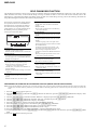
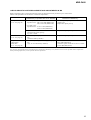
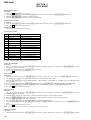
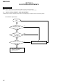
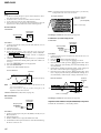
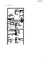
1. When replacing the following parts, perform the adjustments
and checks with in the order shown in the following table.
2. Set the test mode when performing adjustments.
After completing the adjustments, exit the test mode.
Perform the adjustments and checks in “group Service” of the
test mode.
3. Perform the adjustments to be needed in the order shown.
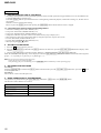
4. Use the following tools and measuring devices.
• Check Disc (MD) (TDYS-1) (Parts No. 4-963-646-01)
• Test Disk (MDW-74/GA-1) (Parts No. 4-229-747-01)
• Laser power meter LPM-8001 (Parts No. J-2501-046-A)
or
MD Laser power meter 8010S (Parts No. J-2501-145-A)*1
• Oscilloscope (Measure after performing CAL of prove.)
• Digital voltmeter
• Thermometer
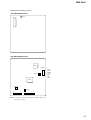
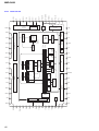
• Jig for checking BD (MD) board waveform
(Parts No. : J-2501-196-A)
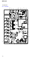
5. When observing several signals on the oscilloscope, etc.,
make sure that VC and ground do not connect inside the oscilloscope.
(VC and ground will become short-circuited.)
6. Using the above jig enables the waveform to be checked without the need to solder.
(Refer to Servicing Note on page 7.)
7. As the disc used will affect the adjustment results, make sure
that no dusts nor fingerprints are attached to it.
*1 Laser power meter
When performing laser power checks and adjustment (electrical
adjustment), use of the new MD laser power meter 8010S (Part
No. J-2501-145-A) instead of the conventional laser power meter is convenient.
It sharply reduces the time and trouble to set the laser power
meter sensor onto the objective lens of optical pick-up.
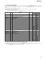
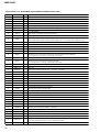
Parts to be replaced
Adjustment
5-8.
Initial setting of adjustment value
5-9.
Recording of Iop information
Optical
Pick-up
IC101
IC12
IC201
IC933
IC195
D101
5-10. Temperature compensation
offset adjustment
5-11. Laser power adjustment
5-12. Iop NV Save
5-13. Traverse adjustment
5-14. Focus bias adjustment
5-17. Auto gain adjustment
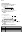
5-7-4. AUTO CHECK
35