1
Technical Reference
Software
Version 10.03 - July 2010
Studio Production Server
XS Series DISK RECORDER - Version 10.03 - Software Technical Reference Manual
EVS Broadcast Equipment SA – July 2010
Issue
10.03.C
C OPYRIGHT
EVS Broadcast Equipment – Copyright © 2009-2010. All rights reserved.
D ISCLAIMER
The information in this manual is furnished for informational use only and subject
to change without notice. While every effort has been made to ensure that the
information contained in this user manual is accurate, up-to-date and reliable,
EVS Broadcast Equipment cannot be held responsible for inaccuracies or errors
that may appear in this publication.
I MPROVEMENT R EQUESTS
Your comments will help us improve the quality of the user documentation. Do not
hesitate to send im provement requests, or report any error or inaccuracy on this
user manual by e-mail to [email protected].
I
Issue
10.03.C
XS Series DISK RECORDER – Version 10.03 - Software Technical Reference
EVS Broadcast Equipment SA – July 2010
Table of Contents
TABLE OF CONTENTS .................................................................................................... II WHAT’S NEW? ................................................................................................................. V 1. EVS SOFTWARE ..................................................................................................... 1 1.1 INTRODUCTION ..........................................................................................................................1 1.2 EVS MAIN MENU ........................................................................................................................2 1.2.1 EVS Screen Layout .................................................................................................................2 1.2.2 Tips to Move Inside the EVS Software ....................................................................................2 1.2.3 Starting an Application ............................................................................................................3 1.2.4 Commands Available from the Main Menu .............................................................................3 1.2.5 Configurations Available on XS Systems ................................................................................3 1.3 AUDIO & VIDEO CHANNEL PARAMETERS (AVCFG) ...............................................................4 1.3.1 Introduction .............................................................................................................................4 1.3.2 How to Modify A/V Channel Parameters .................................................................................4 1.3.3 Audio & Video Parameters overview .......................................................................................5 Lock Video Configuration ........................................................................................................................................... 5 Base Configuration..................................................................................................................................................... 5 Loop Rec .................................................................................................................................................................... 6 Clip Capacity .............................................................................................................................................................. 6 Video players ............................................................................................................................................................. 7 Video recorders .......................................................................................................................................................... 7 Super Motion REC ..................................................................................................................................................... 7 Audio Format .............................................................................................................................................................. 8 Audio Type ................................................................................................................................................................. 8 Lipsync ....................................................................................................................................................................... 8 Audio Full Scale ......................................................................................................................................................... 9 REC 1 on all REC ...................................................................................................................................................... 9 3D Dual-Stream ......................................................................................................................................................... 9 Ancillary Mode............................................................................................................................................................ 9 Sample Rate Converter.............................................................................................................................................. 9 1.3.4 Channels Overview ...............................................................................................................10 Type ......................................................................................................................................................................... 10 CTRL ........................................................................................................................................................................ 10 Port ........................................................................................................................................................................... 10 REC .......................................................................................................................................................................... 11 Audio Tracks ............................................................................................................................................................ 11 Audio Monitoring (A. Mon.) ...................................................................................................................................... 12 1.3.5 Dolby Audio Management .....................................................................................................12 Some Definitions ...................................................................................................................................................... 12 Dolby configurations in XS Servers.......................................................................................................................... 12 1.3.6 3 D & 1080p Dual-Stream Management ...............................................................................13 Principle ................................................................................................................................................................... 13 Possible Channels Configurations ........................................................................................................................... 13 3D Configuration ...................................................................................................................................................... 13 1080p Configuration ................................................................................................................................................. 13 1.3.7 OSD, Video and Audio Signals on COHX in Rec/Play ..........................................................14 1.4 MAINTENANCE MENU..............................................................................................................17 1.4.1 Advanced Parameters...........................................................................................................18 How to Modify Advanced Parameters ...................................................................................................................... 18 Codecs Availability and Options Depending on the Video Standard and the Hardware .......................................... 19 Video Disk Block Size .............................................................................................................................................. 21 Operational Disk Size............................................................................................................................................... 21 Rec HD-> SD Low Latency ...................................................................................................................................... 22 Vertical Interpolator and Four Lines Interpolation .................................................................................................... 22 1.4.2 Configuration .........................................................................................................................23 How to Enter the Configuration Window .................................................................................................................. 23 How to Modify an Item in the Configuration Window ............................................................................................... 23 II
XS Series DISK RECORDER - Version 10.03 - Software Technical Reference Manual
EVS Broadcast Equipment SA – July 2010
Issue
10.03.C
Hardware Revisions Area ........................................................................................................................................ 24 Software Releases Area .......................................................................................................................................... 24 Network Area ........................................................................................................................................................... 25 Video & Audio Area .................................................................................................................................................. 26 Ref & Phase Area .................................................................................................................................................... 27 1.4.3 RAID Configuration ...............................................................................................................28 RAID Construction ................................................................................................................................................... 28 RAID Configuration .................................................................................................................................................. 29 1.4.4 Options..................................................................................................................................30 Accessing the Options Menu ................................................................................................................................... 30 Introduction .............................................................................................................................................................. 30 Display ..................................................................................................................................................................... 30 Expiration and Warning ............................................................................................................................................ 31 How to Enter New License Codes ........................................................................................................................... 31 How to Remove a License Code.............................................................................................................................. 32 How to Check Hardware Key (dongle) Information .................................................................................................. 32 1.4.5 Clear Video Disks .................................................................................................................33 1.4.6 Force Load Clips ...................................................................................................................33 1.4.7 Phase Definition ....................................................................................................................33 Standard Definition................................................................................................................................................... 33 High Definition .......................................................................................................................................................... 34 Commands ............................................................................................................................................................... 34 1.4.8 Default Application ................................................................................................................35 How to Define a Default Application......................................................................................................................... 35 How To Remove the Default Application ................................................................................................................. 35 1.4.9 Default Parameters ...............................................................................................................36 1.4.10 1.4.11 1.4.12 1.4.13 2. Default Parameters for all Applications .................................................................................................................... 36 Default to VGA ......................................................................................................................36 TS Calibration .......................................................................................................................36 Set Time................................................................................................................................37 Hardware Check / Raid Rebuild ............................................................................................37 Disk Errors and Disconnection ................................................................................................................................. 37 Disks Monitoring....................................................................................................................................................... 40 Rebuild Process ....................................................................................................................................................... 42 Retrieving Logs ........................................................................................................................................................ 43 BOOTWINS & ERROR MESSAGES ..................................................................... 44 2.1 INTRODUCTION ........................................................................................................................44 2.2 INITIALIZING THE DISKS..........................................................................................................44 2.2.1 SCSI Disks ............................................................................................................................44 Step 1: Initialization Start ......................................................................................................................................... 44 Step 2: Disk Status................................................................................................................................................... 45 Step 3: Board Capacity Display ............................................................................................................................... 46 Possible Error Messages ......................................................................................................................................... 46 2.2.2 SAS Disks .............................................................................................................................47 2.3 READING THE CONFIGURATION FILE ...................................................................................47 2.4 INITIALIZING THE MICROCODE ..............................................................................................49 2.5 DISK DATA RECOVERY ...........................................................................................................50 3. MONITORING ......................................................................................................... 52 3.1 SDTI NETWORK MONITORING ...............................................................................................52 3.1.1 Information Available on the Screen .....................................................................................52 Data Displayed ......................................................................................................................................................... 52 Background Colour .................................................................................................................................................. 53 Text Colour............................................................................................................................................................... 53 Link Colour ............................................................................................................................................................... 53 Possible Actions ....................................................................................................................................................... 53 3.1.2 How to Disconnect a Machine from the Server .....................................................................54 3.2 SERVER MONITORING ............................................................................................................55 3.2.1 SCSI Disk Status ..................................................................................................................55 3.2.2 SAS Raids and Disks Status .................................................................................................56 RAID Type................................................................................................................................................................ 56 III
Issue
10.03.C
XS Series DISK RECORDER – Version 10.03 - Software Technical Reference
EVS Broadcast Equipment SA – July 2010
3.2.3 3.2.4 3.2.5 3.2.6 3.2.7 3.2.8 4. 4.1 4.2 4.3 4.4 5. 5.1 5.2 6. 6.1 6.2 6.3 RAID Status ............................................................................................................................................................. 56 External Array Status ............................................................................................................................................... 57 Disk Status ............................................................................................................................................................... 57 Genlock Status ......................................................................................................................58 Analog LTC Status ................................................................................................................59 Timecode Statuses ...............................................................................................................59 Timecode Monitoring on SD Recorders ................................................................................61 Timecode Monitoring on HD Recorders ................................................................................61 Log Management ..................................................................................................................61 Log File Types.......................................................................................................................................................... 62 Criticality Levels ....................................................................................................................................................... 62 Extracting Log Files.................................................................................................................................................. 62 ASRUNLOG............................................................................................................ 63 PURPOSE..................................................................................................................................63 AS RUN LOG MECHANISM ......................................................................................................63 SERVER AS RUN LOG FILE .....................................................................................................64 AS RUN LOG FILE CONTENT ..................................................................................................64 PROTOCOLS ......................................................................................................... 65 CONTROL PROTOCOLS ..........................................................................................................65 MONITORING PROTOCOL .......................................................................................................68 POSSIBLE CLIP IDENTIFIERS ............................................................................. 69 LSM ID .......................................................................................................................................69 UMID ..........................................................................................................................................69 VARID ........................................................................................................................................69 REGIONAL CONTACTS ................................................................................................. 71 IV
XS Series DISK RECORDER - Version 10.03 - Software Technical Reference Manual
EVS Broadcast Equipment SA – July 2010
Issue
10.03.C
What’s New?
The following table describes the sections updated to reflect the new and updated
features on Multicam version 10.03.
In the user manual, the icon
has been added on left margin to highlight
information on new and updated features.
Click the section number (or the description) in the table to jump directly to the
corresponding section.
Updates for Multicam version 10.03
1.4
Update: Maintenance Menu for RAID Configuration (SAS
Disks)
1.4.1
New codec: Apple ProRes 422 LT
1.4.3
Raid Configuration for SAS Disks
1.4.13
Hardware check and Rebuild process with SAS disks.
2.2
Initializing process with SAS disks.
3.2.2
Update: Server Monitoring page for Raid & Disk Status
4
As Run Log function
V
XS Series DISK RECORDER - Version 10.03 - Software Technical Reference Manual
EVS Broadcast Equipment SA – July 2010
Issue
10.03.C
1. EVS Software
1.1
INTRODUCTION
The EVS software is used for configuration and maintenance operations. It is also
used to select which application to run, since EVS disk recorders have the ability
to run various dedicated applications (Video Server, …).
When turning on the EVS mainframe, the first step is the PC boot sequence,
followed by the boot of the video I/O boards, and finally the EVS software is
started.
If a default application has been previously selected, this application will start
automatically after a few seconds if no key is hit.
If a default application has not been defined or if the space bar is hit, the system
will remain in the EVS main menu (see snapshot on next page) and wait for the
operator's next command.
1
Issue
10.03.C
XS Series DISK RECORDER – Version 10.03 - Software Technical Reference
EVS Broadcast Equipment SA – July 2010
1.2
EVS MAIN MENU
1.2.1
EVS SCREEN LAYOUT
Title bar: the first line of the VGA screen is the title bar. It contains the EVS
software revision and current date and time.
Task bar: the last line of the VGA screen is the task bar. It contains a summary of
the keyboard controls available.
Application window: this window contains the list of all applications installed on
the system.
Configuration windows: the windows show the hardware configuration of the
system.
Message window: messages are displayed in this space to provide more
information on the current selection.
1.2.2
TIPS TO MOVE INSIDE THE EVS SOFTWARE
• The active window is always shown with a double frame.
• Press the UP ARROW, the DOWN ARROW or the <TAB> key to change the
selection inside the active window.
• Press the <SPACE BAR> to toggle between pre- defined values.
• Press ENTER to select an item or to confirm an entry.
• Press ESC to go back to the previous menu or to cancel an entry.
2
XS Series DISK RECORDER - Version 10.03 - Software Technical Reference Manual
Issue
10.03.C
EVS Broadcast Equipment SA – July 2010
1.2.3
STARTING AN APPLICATION
Select the appropriate application from the Applications list, then press ENTER to
confirm the selection.
1.2.4
COMMANDS AVAILABLE FROM THE MAIN MENU
The UP ARROW and DOWN ARROW keys of the keyboard can be used to select
an application. The purple line show s the current selection. The black line shows
the default application.
The ENTER key is used to start the selected application.
Press F7 to make the currently selected application the new default one. The
default application is automatically started every time the EVS program is entered.
When the application currently selected is already the default application,
pressing F7 will disable the default application and the system will remain in the
EVS Main menu every time the EVS software is launched.
Press F8 to immediately open the Channel Config window related to the selected
application. Press ALT + Q to come back to main menu.
Press F9 to enter the Maintenance menu.
To exit the EVS software and go back to the DOS prompt, press simultaneously
ALT + Q and confirm with ENTER. To restart the EVS software from the DOS,
simply type RUN.
1.2.5
CONFIGURATIONS AVAILABLE ON XS SYSTEMS
EVS XS Servers : Configurations
PGM1 (Mix)
PGM2/PRV
O REC
BDR222
CAM1
BDR444
PGM1 (Cut)
1 REC
BDR444
BDR222
CAM1
2 REC
CAM1
CAM2
BDR414
PGM1 (Mix)
PGM2/PRV
PGM3
PGM4
PGM1 (Mix)
PGM2/PRV
PGM3
CAM1
BDR414
PGM1 (Mix)
CAM2
PGM2/PRV
BDR444
BDR222
CAM1
3 REC
PGM1 (Mix)
PGM2/PRV
PGM3
PGM4
PGM1 (Mix)
PGM2/PRV
PGM3
CAM1
4-Channel
BDR441
4-Channel
BDR414
4-Channel
BDR444
2-Channel
BDR222
PGM1 (Cut)
CAM2
CAM3
CAM1
CAM3
BDR444
4 REC
BDR441
CAM1
CAM1
CAM2
CAM2
CAM3
CAM4
PGM1 (Cut)
CAM2
CAM3
BDR444
CAM4
BDR441
3
Issue
10.03.C
XS Series DISK RECORDER – Version 10.03 - Software Technical Reference
EVS Broadcast Equipment SA – July 2010
1.3
AUDIO & VIDEO CHANNEL PARAMETERS
(AVCFG)
1.3.1
INTRODUCTION
Important
Most parameters are factory preset, and should not be modified without
advice of qualified EVS staff. Improper values for some parameters will
prevent the proper operation of the system .
Please refer to the parameters’ charts for correct values (See section
1.4.9 ‘Default Parameters’, on page 36).
Each application has its own set of parameters. When the user selects an
application in the EVS main menu and press F8 (Parameters), the A/V Channels
Configuration window (also called AVCFG) appears:
This window is used to define video & audio channels, type and configuration of
recorders, audio format and audio-video synchronization parameter. All the
parameters are described in this section.
1.3.2
HOW TO MODIFY A/V CHANNEL PARAMETERS
1. From the EVS main menu, press F9 to open the Maintenance menu.
2. Select the ‘Channel Parameters’ item and press ENTER.
3. Select the Application to configure and press ENTER.
The A/V Channel Config window appears.
4. Use the <TAB> key to move from one box to the next one. Some information
about the current parameter is displayed in the INFO area.
4
XS Series DISK RECORDER - Version 10.03 - Software Technical Reference Manual
EVS Broadcast Equipment SA – July 2010
Issue
10.03.C
5. Press <TAB> or the arrow keys to move across the different parameters in the
window.
6. When the desired field is selected, modify the parameter to its new value by
pressing the <SPACE BAR> or by entering its numeric value and then pressing
ENTER to validate.
7. Press F3 to enter the Advanced Parameters.
8. Press F4 to save the current configuration. A dialog Box appears to enter a
name.
9. Press F5 to load the list of configurations previously saved.
10. Press ALT + Q to exit the A/V Channel Config window.
OR:
1. From the ‘Application List’ in the EVS main menu, select the application to
configure and press F8.
2. Continue from step 4.
1.3.3
AUDIO & VIDEO PARAMETERS OVERVIEW
Note:
When Modifying the value of a parameter in the Audio & Video Channel
Config, always press ENTER after changing the value of a parameter to
validate the new choice. Check the channels table in the centre of the
screen to make sure that the changes are reflected there.
L OCK V IDEO C ONFIGURATION
Possible values: Yes / No
This item enables/disables the access to the modifications of the next three items:
Video Players, Video Recorders and Type for REC1.
The video configuration is locked if Option Code 4 (Authorize video configuration
changes) is not active in the Options List.
B ASE C ONFIGURATION
Possible values:
XS Server Sony
XS Server DD35
XS Server Odetics
XS Server Odetics F&K
XS Server VDCP
XS Server VDCP F&K
XS Server AVSP
XS Server IPDP
XS SpotBox Sony
5
Issue
10.03.C
XS Series DISK RECORDER – Version 10.03 - Software Technical Reference
EVS Broadcast Equipment SA – July 2010
XS SpotBox DD35
XS SpotBox Odetics
XS SpotBox Odetics F&K
XS SpotBox VDCP
XS SpotBox VDCP F&K
XS SpotBox AVSP
XS SpotBox IPDP
Video Delay
2-ch VTR
The different configurations appear according to the licence codes that have been
enabled.
Secondary Controller
When you select a Spotbox configuration, you can define secondary controllers by
pressing CTRL-F1.
Limitations
Some configurations (*) lead to the following message to warn the users of the
limitations of the selected configuration:
“ Warning: your parallel selection is not fully operational”
Parallel
VDCP
Odetics
DD35
Remote
*
*
*
IPDirector
*
*
*
Configuration
VDCP, Odetics and DD35 protocols are standard protocols which have not been
developed to work in collaborative mode. Each protocol has its own workspace, so
the actions of the first controller are not always correctly interpreted by the
second controller.
L OOP R EC
This parameter enables/disables the endless loop recording in AVSP
Server/Spotbox configurations. This function is applied to all recorder channels.
C LIP C APACITY
Possible values: Global / Per Channel
This parameter allows selecting the recording mode.
In Global mode, the clip capacity is shared between the different record trains.
Example: When 3 record trains are used, creating a clip of 30 min on REC1 will
take 10 min of recording capacity equally from each record train.
6
XS Series DISK RECORDER - Version 10.03 - Software Technical Reference Manual
EVS Broadcast Equipment SA – July 2010
Issue
10.03.C
In Per Channel mode, the clip capacity is only relevant to the individual record
train. Example: 3 record trains are used, creating a clip of 30 min on REC1 will
take 30 min of recording capacity from the 1 s t record train, but will not affect the
recording capacity of the other two record trains.
The default value depends on the basic configuration:
2-ch VTR
Slave/Server
configurations
Video Delay
Per Channel
Per Channel
Global (locked)
V IDEO PLAYERS
Range: [1…4]
This parameter allows selecting the number of player channels of the application
and the associated audio channels.
V IDEO RECORDERS
Possible values in range: [1…4]
This parameter allows selecting the number of RECORD channels of the
application. The partition of the disk storage between these channels, and the
associated audio channels are automatically updated.
S UPER M OTION REC
This parameter defines the type of Super Motion recorders. The parameter is only
editable if at least 2 channels are available to be used as Super Motion recorders.
Otherwise, the parameter has the value “None” and is not editable.
Six types of record are available:
• None (Standard rate 50/60 Hz)
• Single SD Super Motion 3x Alternate Parity – EVS mode (150/180 Hz)
• Single SD Super Motion 3x Identical Parity (150/180 Hz)
• Single HD Super Motion 2x Alternate Parity – EVS mode (100/120 Hz)
• Single HD Super Motion 3x Alternate Parity – EVS mode
• Double HD Super Motion 2x Alternate Parity – EVS mode
Note
The fault tolerance on the different phases of the super motion camera is
+/- 90% of one field. So there should be no delay between the different
phases when all equipments are genlocked.
7
Issue
10.03.C
XS Series DISK RECORDER – Version 10.03 - Software Technical Reference
EVS Broadcast Equipment SA – July 2010
A UDIO F ORMAT
Possible values: [Analog (A), AES/EBU (D), Embedded (E), Dolby E AES (DY),
Dolby E Embedded (EY)]
This parameter allows selecting the Audio format.
When the Audio Format is set to AES/EBU (D or DY) or Embedded (E or EY), the
analogue audio outputs are used for additional monitoring.
When the Audio Form at is set to Embedded (E or EY), the digital audio (AES/EBU)
outputs are also active.
For more information on Dolby Audio Management, refer to section1.3.5 ‘Dolby
Audio Management’, on page 12.
A UDIO T YPE
Possible values: [1 Track, 2 Tracks, 4 Tracks, 8 Tracks, 16 Tracks]
This parameter allows selecting the type of audio (number of mono audio tracks
associated to each video channel).
The following table specifies the audio types available for the various audio
formats:
Audio
Type
1 track
2 tracks
4 tracks
8 tracks
16 tracks
Analog (A)
X
X
X
Digital
(D - DY)
X
X
X
Embedded
(E - EY)
X
X
X
L IPSYNC
Range for PAL: From -41,458 ms to 14,708 ms Î 848 to 3544 (sam ples)
With 0 ms = 2838
Range for NTSC: from -34,625 to 12,125 ms Î 688 to 2932 (samples)
With 0 ms = 2350
The Lipsync param eter is the delay (in ms) between video and audio signals. A
positive value means video is ahead of audio. A negative value means audi o
ahead of video.
CTRL+UP ARROW or CTRL+DOWN ARROW changes the value per 1 ms step.
CTRL+LEFT ARROW or CTRL+RIGHT ARROW change the value per 5 ms step.
The operator can also enter directly a value with the keyboard.
Note:
This adjustment is done during the RECORD process. A new Lipsync
value will apply for the next recorded pictures only.
8
XS Series DISK RECORDER - Version 10.03 - Software Technical Reference Manual
EVS Broadcast Equipment SA – July 2010
Issue
10.03.C
A UDIO F ULL S CALE
Range of value: [10…30] dBu
The audio full scale parameter (in dB) specifies the maximum audio level for the
analogue outputs on the server.
It allows indirectly defining the head room, as the audio full scale is 4 dB higher
than the head room. As the default value for the audio full scale is 22 dB, the
default value for the head room is 18.
Change the value per 1 dBu step by pressing CTRL+UP ARROW or
CTRL+DOWN ARROW or per 3 dBu step by pressing CTRL+LEFT ARROW or
CTRL+RIGHT ARROW.
REC 1 ON ALL REC
Possible values: [Yes or No]
All audio channels associated to REC1 (CAM A) will be automatically used for all
other RECORD channels if ‘Yes’ is selected.
3D D UAL -S TREAM
Possible values: [OFF or ON]
This parameter activates the 3D Dual-Stream option, which makes it possible to
use the server to record and playback 3D video. The parameter is only available
for users who have subscribed to the 3D Dual-Stream option (licence code 23).
When the 3D Dual-Stream is set to ON, a message informs the user that the video
and player configuration will automatically be adapted into a compatible
configuration. For more information on the 3D Dual-Stream feature, please refer
to the section 1.3.6 ‘3 D & 1080p Dual-Stream Management’, on page 13.
A NCILLARY M ODE
Possible values: [20 bits or 24 bits]
This parameter defines the encoding method used for Digital Audio.
This parameter is solely applicable in SD, allowing you to have the output of the
embedded audio in 20 or 24 bits. In HD, it is always 24 bits.
S AMPLE R ATE C ONVERTER
Possible values: [OFF or ON]
This parameter is available with AES/EBU audio format.
If this parameter is set to OFF, the user has to ensure that the signals are
properly synchronized.
9
Issue
10.03.C
1.3.4
XS Series DISK RECORDER – Version 10.03 - Software Technical Reference
EVS Broadcast Equipment SA – July 2010
CHANNELS OVERVIEW
Channels input/output and name are automatically defined according to the
parameters entered in the fields: Base configuration, Video Players, Video
Recorders and SLSM Rec.
The player channels are allocated first (starting with OUT1), then the record
channels are allocated (starting with IN1)
Note:
To modify the parameters included in the “Channels’ area”, press F3 to
enter the Advanced Configuration mode
T YPE
Possible values: [Rec, Play, SLSM Rec, SLSM Rec. 1, SLSM Rec. 2, SLSM Rec. 3]
This parameter is automatically set according to the settings of the previous ones.
It defines the type of channel and depends on the values of Video Players, Video
Recorders and SLSM Rec.
CTRL
Possible values: [Sony, DD35, VDCP, VDCP F&K, Odetics, Odetics F&K, Edit Rec,
AVSP, LinX, IPDP]
This parameter defines which system or protocol controls the current channel.
This parameter is automatically set and not editable when the Base Configuration
is set to Video Delay.
P ORT
Range: [1 … 6]
This parameter defines the RS422 port number that controls each channel. These
fields are not available with Video Delay configurations
Note:
A single Sony BVW serial connection can control multiple PGM channels
which are ganged on an XS server. It is therefore possible to assign the
same RS422 port number (#n), which corresponds to a Sony BVW
protocol, to several PGM channels on the same EVS server.
A single Odetics or VDCP serial connection can control two PGM paired
channels, in a Fill and Key configuration, on an XS server. It is therefore
possible to assign the same R S422 port number (#n), w hich corresponds
to a VDCP or Odetics protocol, to the Fill and Key player channels of one
XS server. The first channel will be assigned as the Fill channel and the
second will automatically be the Key channel.
10
XS Series DISK RECORDER - Version 10.03 - Software Technical Reference Manual
Issue
10.03.C
EVS Broadcast Equipment SA – July 2010
REC
For a player channel, this parameter defines which record train is the default
source.
For a recorder channel, two parameters are available:
• Recording Capacity: (% Disk) Percentage of disk space allocated to each
channel. Total of all values must not exceed 100%.
• Loop/No Loop: depends on the value of Loop Rec, previously described. Always
forced to “Loop” with the current version.
A UDIO T RACKS
The audio tracks are listed from A1 up to A16:
• A1 to A16 IN: Mono audio inputs of the current channel.
• A1 to A16 OUT: Mono audio output of the current channel.
Audio Format
Possible values: [Analog (A), Digital AES/EBU (D), Dolby E AES (DY), Embedded
(E), Dolby E Embedded (EY)]
The available values depend on the type of audio connectors defined in EVS
hardware configuration:
None
4 DB15 Analog + 16 BNC Digital
4 DB15 Analog + 4 DB15 Digital
E - EY
E - EY - A – D - DY
Audio Channel
Range: [1 … 64]
This parameter allows selecting each audio channel in the selected audio format.
In 16 audio configurations, the PAGE DOWN and PAGE UP keys make it possible
to navigate through the list of 16 audio channels.
The values depend on the audio format and available connectors:
Analog (A)
4 DB15 Analog + 16 BNC Digital or
4 DB15 Analog + 4 DB15 Digital
1 – 8
Digital
(D - DY)
1 – 16
Embedded
(E - EY)
1 – 64
11
Issue
10.03.C
XS Series DISK RECORDER – Version 10.03 - Software Technical Reference
EVS Broadcast Equipment SA – July 2010
Audio Gain
Range: [from -90dB to +23.5dB]
This parameter allows the operator to adjust the audio gain for each audio track.
The adjustments are done by pressing CTRL-↓/↑ (±0.75dB steps) or SHIFT-↓ /↑
(±6dB steps).
CTRL+UP ARROW or CTRL+DOWN ARROW changes the value per 0.75 dB step.
CTRL+LEFT ARROW or CTRL+RIGHT ARROW change the value per 6 dB step.
A UDIO M ONITORING (A. M ON .)
This parameter defines the audio monitoring outputs, selects the type of audio and
allows adjusting the audio gain for each channel.
1.3.5
DOLBY AUDIO MANAGEMENT
S OME D EFINITIONS
Dolby Digital or Dolby 5.1 or AC-3, is an audio coding system containing up to 6
discrete channels of sound , with 5 channels for normal-range speakers (20 Hz 20,000 Hz) (Right front, Center, Left Front, Right Rear and Left Rear) and one
channel (20 Hz - 120 Hz) for the LFE, or subwoofer.
Dolby E is a professional coding system optim ized for the distribution of
surround and multichannel audio through two-channel postproduction and
broadcasting infrastructures, or for recording surround audio on two audio tracks
of conventional digital video tapes, video servers, communication links, switchers,
and routers.
D OLBY CONFIGURATIONS IN XS S ERVERS
Case 1: The 5.1 audio signal is carried on 6 discrete PCM audio channels
• Available on an XS in all configurations
• The audio can be analogue, digital or embedded depending on the configuration
• In AES audio, if the audio is correctly genlocked to the video, the sample rate
converter can be switched off.
Case 2: The 5.1 audio signal is coded in the two-channels Dolby E
standard
• Dolby E over AES/EBU links
o
Set the configuration of the pair of channels carrying the Dolby E signal to
“DY” in the AVCFG. This has two effects :
• It disables the sample rate converter on the input channels
• It forces all transitions to a hard cut.
If the sample rate converter is activated and the audio configuration is a mix
between PCM audio over AES and Dolby E over AES, the sample rate converter
will only be applied to the PCM over AES signal.
12
XS Series DISK RECORDER - Version 10.03 - Software Technical Reference Manual
EVS Broadcast Equipment SA – July 2010
Issue
10.03.C
• Dolby E Embedded in the SDI/HD SDI stream
o
Set the configuration of the pair of channels carrying the Dolby E signal to
“EY” in the AVCFG. This will force the transition to a hard cut.
o
The sample rate converter parameter does not apply to embedded audio.
The Dolby E transitions will be correct as long as :
• the configuration is correct
• the AES stream containing Dolby E is correctly synchronised with the video
Dolby E transitions will not be correct (2 frames of mute at the transitions) if the
AVCFG is set to E instead of EY or D instead of DY.
Audio effects (scrub, slow motion) are not possible in Dolby E. If they are used
anyway, the audio will be muted.
1.3.6
3 D & 1080P DUAL-STREAM MANAGEMENT
P RINCIPLE
The 3D and 1080p features is based on the use of two physical channels
(recorders or players) seen by the server as a logical channel. Consequently, two
physical recorders or players are required but only one is assigned in the
Channels Configuration. These two configurations require the record and playout
on synchronous channels.
P OSSIBLE C HANNELS C ONFIGURATIONS
The possible video configurations are:
• 1IN 1 OUT
• 2IN 0 OUT
• 0 IN 2 OUT
3D C ONFIGURATION
With the 3D feature, the two physical cameras will record the same scene with a
slightly different angle to mimic the angle difference between the human eyes.
The configuration is set up in the Channels Configuration screen, via the 3D DualStream option. See also the section ‘3D Dual-Stream’, on page 9.
1080 P C ONFIGURATION
With the 1080p feature, the two physical cameras make it possible to get the
progressive image scan with a vertical resolution of 1080 pixels.
The configuration is adapted in the AVCFG when you select the 1080p video
standard in the AVCFG main screen. See also the section ‘Video & Audio Area’, on
page 26.
13
Issue
10.03.C
XS Series DISK RECORDER – Version 10.03 - Software Technical Reference
EVS Broadcast Equipment SA – July 2010
Important
When you activate or deactivate the 1080p video standard, it is highly
recommended to check and set manually the desired channel
configuration in the Channels Configuration screen before you launch the
requested application.
1.3.7
OSD, VIDEO AND AUDIO SIGNALS ON COHX IN REC/PLAY
Embedded audio is present on the monitoring of the codecs in rec.
The following table summarizes what is present on each of the BNC of a COHX
input/output.
COHX rear panel connector:
SD Mode - Input
HD Mode - Input
14
XS Series DISK RECORDER - Version 10.03 - Software Technical Reference Manual
EVS Broadcast Equipment SA – July 2010
Issue
10.03.C
SD Mode - Output
HD Mode - Output
15
Issue
10.03.C
XS Series DISK RECORDER – Version 10.03 - Software Technical Reference
EVS Broadcast Equipment SA – July 2010
SD Codec in Rec
BNCs
Video
J8
J6
J7
J3
J1
SD Input
SD signal of J8 (IN1)
SD signal of J8
Hardware loop of BNC 1
SD SDI or CVBS signal of BNC 1 with OSD
J4 SD signal of BNC 1 with OSD
HD Codec in Rec
BNCs
Video
J8
J6
J7
J3
J1
HD Input
HD signal of J8 (IN1)
HD signal of J8
SD downconverted signal of BNC 1
SD SDI or CVBS signal of BNC 1 with OSD
(08.03)
J4 HD signal of BNC 1 with OSD
Embedded Audio (if
present at input)
n/a
Audio of J8
Audio of J8
Audio of BNC 1
Audio of BNC 1 only in
SDI
Delay
Phase
n/a
n/a
n/a
n/a
n/a
n/a
n/a
n/a
n/a
n/a
Audio of BNC 1
n/a
n/a
Embedded Audio (if
present at input)
n/a
Audio of J8
Audio of J8
Audio of BNC 1
Audio of BNC 1 only in
SDI
Delay
Phase
n/a
n/a
n/a
No*
No*
n/a
n/a
n/a
Adjustable
Adjustable
n/a
n/a
Audio of BNC 1
* No delay if the Rec HD -> SD Low Latency setting is set to ‘ON’ in the Advanced Parameters window of the
selected application in the EVS software.
SD Codec in Play
BNCs
Video
J8
J6
J7
J3
J1
J4
n/a
SD output
SD output
Hardware loop of BNC 1
SD SDI or CVBS output with OSD
SD signal output with OSD
HD Codec in Play
BNCs
Video
J8
J6
J7
J3
J1
J4
16
n/a
HD output
HD output
SD downconverted output
SD SDI or CVBS signal output with OSD
HD output with OSD
Embedded Audio
(depending on the avcfg
configuration)
n/a
Yes
Yes
n/a
Only in SDI
Yes
Embedded Audio
(depending on the avcfg
configuration)
n/a
Yes
Yes
Yes
Only in SDI
Yes
XS Series DISK RECORDER - Version 10.03 - Software Technical Reference Manual
EVS Broadcast Equipment SA – July 2010
1.4
Issue
10.03.C
MAINTENANCE MENU
The Maintenance menu contains various options to configure and check the
system. These options are described in details in the next sections.
According to the type of disks detected at bootwins, the Maintenance menu will
slightly differ.
To select an option, press the UP ARROW and DOWN ARROW keys of the
keyboard to highlight the corresponding line and press ENTER or press the key
corresponding to the character between brackets.
To go back to the Application window, press ESC on the keyboard.
SCSI Disks
SAS Disks
17
Issue
10.03.C
1.4.1
XS Series DISK RECORDER – Version 10.03 - Software Technical Reference
EVS Broadcast Equipment SA – July 2010
ADVANCED PARAMETERS
Important
Most parameters are factory preset, and should not be modified without
advice of qualified EVS staff.
Improper values for some parameters will prevent the proper operation of
the system. Please refer to the parameters’ charts for correct values.
(See section 1.4.9 ‘Default Parameters’, on page 36)
H OW TO M ODIFY A DVANCED P ARAMETERS
1. Press F9 to open the Maintenance menu.
2. Select the ‘Advanced Parameters’ item and press ENTER.
3. Press the UP ARROW and DOWN ARROW keys to select the parameter to
modify and press ENTER.
4. Enter the desired value, and then press ENTER.
5. When all parameters are set, press ESC.
A confirmation message is displayed, press ENTER.
18
XS Series DISK RECORDER - Version 10.03 - Software Technical Reference Manual
Issue
10.03.C
EVS Broadcast Equipment SA – July 2010
C ODECS A VAILABILITY AND O PTIONS D EPENDING ON THE
V IDEO S TANDARD AND THE H ARDWARE
SD 625i
COHX
Codec Type SD MJPEG Standard
Bitrate 20-100 Mbps
Default : 30 Mbps
576 lines
Recorded video lines (L23-310 ; L336-623) default
SD IMX (D10)
DVCPro 50
30 ; 40 ; 50 Mbps
50 Mbps
Default : 30 Mbps
Default : 50 Mbps
608 lines
(L7-310 ; L320-623)
576 lines
(L23-310 ; L335-622)
592 lines
(L15-310 ; L328-623)
608 lines
(L7-310 ; L320-623)
SD 525i
COHX
Codec Type SD MJPEG Standard
Bitrate 20-100 Mbps
Default : 30 Mbps
SD IMX (D10)
DVCPro 50
30 ; 40 ; 50 Mbps
50 Mbps
Default : 30 Mbps
Default : 50 Mbps
512 lines
(L7-262 ; L270-525)
496 lines
Recorded video lines (L16-23 ; L278-525) default
480 lines
(L23-262 ; L285-524)
480 lines
(L23-262 ; L286-525)
512 lines
(L7-262 ; L270-525)
HD 1080i/1080p
50Hz
COHX
Codec HD
Type MJPEG
EVS
Bitrate
(Mbps)
HD
HD
MJPEG
MPEG2
Standard Intra
AVID
AVID
DNxHD DNxHD
AVID
DNxHD
(10-bit)
DVCPro
Apple
Apple
Apple
Apple
ProRes ProRes ProRes ProRes HD
422 LT 422
422 HQ 422 HQ
(10-bit)
120
Mbps
185
Mbps
185
Mbps
85
Mbps
120
Mbps
185
Mbps
185
Mbps
100
Mbps
120
185
185
100
20-360
20-360
20-360
1-120
121-185
121-185
85
Default :
Default :
Default :
Default: Default :
Default :
Default: Default: Default: Default: Default :
100
100
100
120
185
185
85
120
185
185
100
Horizontal
Resolution 960
1920
1920
1920
1920
1920
1920
1920
1440
960
960
1152
1152
1152
1280
(default)
1280
(default)
1280
(default)
1372
1372
1372
1440
1440
1440
1536
1536
1536
1600
1600
1600
1920
1920
1920
19
Issue
10.03.C
XS Series DISK RECORDER – Version 10.03 - Software Technical Reference
EVS Broadcast Equipment SA – July 2010
HD 1080i/1080p
59,94Hz
COHX
Codec HD
Type MJPEG
EVS
Bitrate
(Mbps)
HD
HD
MJPEG
MPEG2
Standard Intra
AVID
AVID
DNxHD DNxHD
AVID
DNxHD
(10-bit)
DVCPro
Apple
Apple
Apple
Apple
ProRes ProRes ProRes ProRes HD
422 LT 422
422 HQ 422 HQ
(10-bit)
145
Mbps
220
Mbps
220
Mbps
102
Mbps
145
Mbps
220
Mbps
220
Mbps
100
Mbps
102
145
220
220
100
20-360
20-360
20-360
1-145
146-220
146-220
Default:
Default:
Default:
Default: Default:
Default:
Default: Default: Default: Default: Default :
100
100
100
145
220
220
102
145
220
220
100
Horizontal
Resolution 960
1920
1920
1920
1920
1920
1920
1920
1280
960
960
1152
1280
(default)
1152
1280
(default)
1152
1280
(default)
1372
1372
1372
1440
1440
1440
1536
1536
1536
1600
1600
1600
1920
1920
1920
HD 720p
50Hz
COHX
Codec HD
Type MJPEG
EVS
Bitrate
20-360
(Mbps)
AVID
AVID
DNxHD DNxHD
AVID
DNxHD
(10-bit)
DVCPro
Apple
Apple
Apple
Apple
ProRes ProRes ProRes ProRes HD
422 LT 422
422 HQ 422 HQ
(10-bit)
120
Mbps
185
Mbps
185
Mbps
85
Mbps
120
Mbps
185
Mbps
185
Mbps
100
Mbps
85
120
185
185
100
20-360
20-360
1-120
121-185
121-185
Default :
Default :
Default :
Default: Default :
Default :
Default: Default: Default: Default: Default :
100
100
100
120
185
185
85
120
185
185
100
1280
1280
1280
1280
1280
1280
1280
960
Horizontal
Resolution 640
20
HD
HD
MJPEG
MPEG2
Standard Intra
640
640
768
(default)
768
(default)
768
960
960
960
1024
1024
1024
1280
1280
1280
(default)
XS Series DISK RECORDER - Version 10.03 - Software Technical Reference Manual
Issue
10.03.C
EVS Broadcast Equipment SA – July 2010
HD 720p
59,94Hz
COHX
Codec HD
Type MJPEG
EVS
Bitrate
(Mbps)
HD
HD
MJPEG
MPEG2
Standard Intra
AVID
DNxHD
AVID
DNxHD
AVID
DNxHD
(10-bit)
DVCPro
Apple
Apple
Apple
Apple
ProRes ProRes ProRes ProRes HD
422 LT 422
422 HQ 422 HQ
(10-bit)
145
Mbps
220
Mbps
220
Mbps
102
Mbps
145
Mbps
220
Mbps
220
Mbps
100
Mbps
145
220
220
100
20-360
20-360
20-360
1-145
146-220
146-220
102
Default:
Default:
Default:
Default: Default:
Default:
Default: Default: Default: Default: Default :
100
100
100
145
220
220
102
145
220
220
100
1280
1280
1280
1280
1280
1280
1280
960
Horizontal
Resolution 640
640
640
768
(default)
768
(default)
768
960
960
960
1024
1024
1024
1280
1280
1280
(default)
Note:
The dynamic bitrate management system modifies compression tables for
each recorded field to keep the bitrate of the encoded stream as close as
possible to the target. A higher bitrate means better picture quality and
less storage capacity but a higher bandwidth is required. Improper values
can lead to exceed disks perform ance, causing frozen pictures during
playback.
Important
Some video formats allowed on XS hardware create clips that are not
compatible with previous hardware. When an incompatible format is
selected, a warning will be issued at the starting up of the application. In
addition, the video format information displayed on the Shift-F2 page of
the Multicam indicates any incompatible inform ation.
V IDEO D ISK B LOCK S IZE
[8 MB]
This parameter indicates the size (in KB) of data blocks to be recorded to or read
from the disks.
O PERATIONAL D ISK S IZE
Range: [0…100]
This parameter indicates the percentage of the disks actually used to store the
data. Restricting access to the centre part of the drives increases the performance
of the system but decreases capacity.
21
Issue
10.03.C
XS Series DISK RECORDER – Version 10.03 - Software Technical Reference
EVS Broadcast Equipment SA – July 2010
R EC HD-> SD L OW L ATENCY
Possible Values: Off / On
This parameter prevents the downconverted output of the record channels from
being delayed. This is very useful in setups including high resolution and low
resolution servers.
V ERTICAL I NTERPOLATOR AND F OUR L INES I NTERPOLATION
Possible values: Off / On
This parameter enables or disables the interpolation processes. Select off to
disable the interpolation process, or on to enable the interpolation process
selected by the Four lines interpolation parameter. An interpolation process is
aimed at reducing the vertical jitter of the pictures that is present during slowmotion replays.
This vertical jitter is actually caused by a violation of the fram e parity when
playing back the pictures at less than 100 % speed.
The process consists in re-building new frames to produce a more transparent
result. These frames have to be interpolated - that is calculated by making
suitably weighted averages of adjacent lines. There are 2 interpolation modes: the
2-line interpolator and the 4-line interpolator. The disadvantage of this method is
that it reduces the vertical resolution. This is particularly true with the 4-line
interpolator.
The user can choose between 3 modes:
no interpolation: maximize the vertical bandwidth of the picture but a vertical
jitter appears in “SloMo”. [set 'Vertical Interpolator' to off, whatever the value of
'Four Lines Interpolation']
2-line interpolator: reduces the vertical jitter but the vertical bandwidth is
reduced. [set 'Four Lines Interpolation' to off and 'Vertical Interpolator' to on]
4-line interpolator: the picture is perfectly steady but the vertical bandwidth is
even more reduced. [set both 'Four Lines Interpolation' and 'Vertical Interpolator'
to on]
Note:
All VTRs use interpolation in PLAY VAR mode.
22
XS Series DISK RECORDER - Version 10.03 - Software Technical Reference Manual
EVS Broadcast Equipment SA – July 2010
1.4.2
Issue
10.03.C
CONFIGURATION
This function is used to set the hardware configuration of the system (boards
release numbers, port settings,…).
H OW TO E NTER THE C ONFIGURATION W INDOW
To enter the configuration window, press F9 to open the Maintenance menu, select
'Configuration' and press ENTER. A double frame appears around the
Configuration window, and the cursor blinks next to one of the parameters in this
window part.
H OW TO M ODIFY AN I TEM IN THE C ONFIGURATION W INDOW
1. Press the UP ARROW, DOWN ARROW, or <TAB> keys to select the desired
item.
2. Press the <SPACE BAR> several times until the correct value appears.
3. Select another item to modify or press ESC to go back to the Maintenance
menu.
23
Issue
10.03.C
XS Series DISK RECORDER – Version 10.03 - Software Technical Reference
EVS Broadcast Equipment SA – July 2010
H ARDWARE R EVISIONS A REA
This area indicates, board by board, the detected hardware inside the chassis.
Please refer to the XS Technical Reference Hardware manual for more information
about the hardware.
Some pieces of information cannot be detected:
• Audio In/Out: defines the audio input and output connectors available from the
rear panel.
o
4 DB15 Analog + 16 BNC Digital,
o
4 DB15 Analog + 4 DB15 Digital
o
None
• Video Ch.: the number of available video channels can be adjusted.
Note:
The order of the boards in this list is the same as inside the mainframe,
from top to bottom. The revision of a board located in the front part of the
mainframe is always written on a white label on the left front end of the
board.
Rev: A1 SN: 2307
Board revision
COHX
Board serial number
Board type
S OFTWARE R ELEASES A REA
LSM
This parameter displays the version number of Multicam software installed.
HCT
This parameter displays the version number and release date of HCT microcode
installed.
24
XS Series DISK RECORDER - Version 10.03 - Software Technical Reference Manual
EVS Broadcast Equipment SA – July 2010
Issue
10.03.C
N ETWORK A REA
SDTI
Possible values: [off / 540Mbps Non-Relay / 1485Mbps Non-Relay]
This parameter makes it possible to enable the SD TI option and select the
bandwidth of the network.
On XS servers, there is one pair of SDTI connectors: XNet[2] Non-Relay
connectors can be used at either 540 or 1485 Mbps.
The SDTI circuit is closed only when the Multicam software is started.
Important
The SDTI bandwidth must be identical on all XS servers connected to the
XNet.
If one system is configured with a different bandwidth, it will block the
entire network.
The Disk Block Size parameter must be the same on all XS servers.
Net Name
The Net name defines the machine name on the network. This name is userdefined but cannot exceed 8 characters. Entering a Network Name is not
mandatory because a network number is also assigned to the system, but it is
recommended to easily identify all servers connected to the XNet.
Net Number
Range: [1 … 29]
The Net Number parameter defines the machine num ber on the network. This
number is user-defined and must be unique for each system on the network. When
entering a new number if this number is already assigned to another machine, an
error message will warn the user.
Type
Possible values: [Client, Master, Server]
The type defines the privileges of the XS server on the SDTI network. One XS
server on the network should be set to Server type. If no server is defined, XNet
will not be activated. If more than one server is defined, only the first one to
connect will be the actual server.
Other XS servers on the network can be set either to Master type if they need to
access clips from other servers, or to Client type if their clips must be available
on the network but they don’t need to access clips from other servers.
25
Issue
10.03.C
XS Series DISK RECORDER – Version 10.03 - Software Technical Reference
EVS Broadcast Equipment SA – July 2010
Allowed to access the content of
all EVS video servers on the
network
Can be accessed by other EVS
video servers on the network
SERVER
Yes
Yes
MASTER
Yes
Yes
CLIENT
No
Yes
DB Size
Possible values: [32000 clips]
This parameter defines the size of the network database, i.e. the maximum number
of clips that can be created for the entire SDTI network.
V IDEO & A UDIO A REA
Std
This parameter allows selecting the video standard:
• 625i 50.00 PAL (default fo r SD)
• 525i 59.94 NTSC
• 525i 59.94 NTSC Japan
• 1080i 50.00 PAL ( d ef a u lt f or H D )
• 1080i 59.94 NTSC
• 1080i 59.94 NTSC Japan
• 1080p 50.00 PAL
• 1080p 59.94 NTSC
• 1080p 59.94 NTSC Japan
• 720p 50.00 PAL
• 720p 59.94 NTSC
• 720p 59.94 NTSC Japan
26
XS Series DISK RECORDER - Version 10.03 - Software Technical Reference Manual
Issue
10.03.C
EVS Broadcast Equipment SA – July 2010
Aspect Ratio
In High Definition, this parameter allows the user to select the form at of the image
for the downconverted outputs of the XS (not used in SD configurations).
4:3 L Box
letterbox ( de f a u lt ), the entire width of the 16:9 original
picture is shown, but there are black panels horizontally
above and below the picture.
4:3 Crop
the sides of the 16:9 picture are cut off but the 4:3 fram e is
filled.
16:9
anamorphic, widescreen mode.
The 16:9 picture area is squeezed horizontally to fit inside
the 4:3 space.
In Standard Definition, the parameter defines the aspect ratio of the incoming
video feeds for third party usage, Xedio for instance.
SD Mon OUT
Possible values: [CVBS or SDI]
This parameter specifies the type of output monitoring.
SD Edge Enhancement
Range: [0 – 200%] (Default 66%)
This parameter specifies the value of the edge
downconverted outputs of the XS servers set in HD.
enhancer
for
the
SD
Audio
Possible values: [On or Off]
This parameter enables or disables the Audio.
R EF & P HASE A REA
Ref Type
Possible values: [SD Black Burst, HD Tri-Level Sync]
This parameter allows selecting the genlock reference input between:
• SD Black Burst ( d ef a u lt)
• HD Tri-Level Sync (HD only)
27
Issue
10.03.C
XS Series DISK RECORDER – Version 10.03 - Software Technical Reference
EVS Broadcast Equipment SA – July 2010
Sync Mode
Possible values: [Studio mode, Resync mode]
This parameter allows selecting the frame synchronizer mode between:
• Studio mode: should be used when the video input signals are synchronized.
( d ef a u lt)
• Resync mode: should be used when the video input signals are not
synchronized. In this case, they will be re-synchonized on the digital I/O board.
This can cause a shift of up to 3 fields between the various video input signals.
Genlock
Possible values:[OK or BAD]
This information is automatically displayed.
This parameter checks if the Genlock input is valid.
TC In
This parameter displays the status of the LTC input of the server, and the video
format corresponding to the incoming timecode.
Ex: “TC in 12:24:45:09 PAL” or “TC in 12:24:45:09 NTSC”. If no valid timecode is
detected, the display will show “TC in --:--:--:-- Bad”.
Phase
This parameter shows the value currently set for the main video phase of the
digital video outputs. Refer to the ‘Phase Definition’ section for details.
1.4.3
RAID CONFIGURATION
This option is only available when the XS server is equipped with SAS disks.
RAID C ONSTRUCTION
At the first start, the software builds the SAS disk raids using the following
settings:
• If internal and external storage are detected, both are used
• (5+1) raid configuration with a maximum of 5 spares is used. First, all the raids
are built. The remaining disks are used as spare disks. The construction of
raids starts with internal arrays and carries on with external arrays. A raid can
be created across several hardware arrays.
Note
Only SAS drives from EVS can be used as they are specifically
configured to work with EVS video servers.
28
XS Series DISK RECORDER - Version 10.03 - Software Technical Reference Manual
EVS Broadcast Equipment SA – July 2010
Issue
10.03.C
RAID C ONFIGURATION
This function, from the Maintenance menu, is used to let the users change the
RAID type.
Requested Configuration
This area is used to select the following parameters.
Storage Type
Possibilities are: Internal only, External + Internal and External only.
Number of Raids
Enter the number of raids you want to use.
Raid Configuration Type
Select the Raid configuration type. The software is able to handle two raid
organizations:
• (4+1): raid of 5 disks
• (5+1): raid of 6 disks
Current Configuration
This area is used to display the selected configuration but no parameter can be
updated here.
Refer to section 3.2.2 ‘SAS Raids and Disks Status’ on page 56 for a description
of each field.
29
Issue
10.03.C
1.4.4
XS Series DISK RECORDER – Version 10.03 - Software Technical Reference
EVS Broadcast Equipment SA – July 2010
OPTIONS
A CCESSING THE O PTIONS M ENU
To enter the Options menu, open the Maintenance menu, then press the
UP ARROW and DOWN ARROW keys to highlight the 'Options' line, and press
ENTER. The Options window appears as shown below:
I NTRODUCTION
This window is used to manage software license codes for all applications. This
window only displays the permanent codes you have subscribed to, as well as
valid or expired temporary codes.
To run particular application software and/or specific software options, not only
the software itself is required but also a license key, which is unique for every
option on every system .
This license key can be temporary and be valid only until a defined deadline for
demonstration purposes, or perm anent with no time limit.
Example of line for a PERMANENT option
92
PERM
XS 1 PLAY
Example of line for a TEMPORARY option
95
DEMO
XS 4 PLAY
D ISPLAY
In the Options menu, the highlighted lines show the valid options. The red line is
the current line. Press the UP ARROW and DOWN ARROW keys to move inside
the options list.
When temporary options are present, the limit time for these is shown in the lower
30
XS Series DISK RECORDER - Version 10.03 - Software Technical Reference Manual
EVS Broadcast Equipment SA – July 2010
Issue
10.03.C
part of the Options window.
To go back to the Maintenance menu, press ESC.
E XPIRATION AND W ARNING
When a temporary license key is about to expire, the system will warn the
operator. The warning is displayed every time the EVS software starts, from 2
weeks before the expiration date. The following message appears:
H OW TO E NTER N EW L ICENSE C ODES
To enter new license codes, proceed in one of the following ways:
• If you have received a xxxxx.COD file (xxxxx = serial number of the server for
which this file has been calculated) from EVS, copy this COD file on a USB key
and press simultaneously ALT+U keys. The licence codes will be automatically
read from the USB key and updated into the system.
or
• You can also copy manually the xxxxx.COD file to the C:\ drive, then restart the
EVS menu, enter the Options windows and press simultaneously ALT+F keys.
The codes will be read from the local file on the C:\ drive and updated into the
system.
or
1. Make sure the cursor blinks in the 'Option' box in the lower part of the Options
windows.
2. In the Validation Code field, type the code corresponding to the selected
option (license codes are sent by EVS Technical Support Dpt) and press
ENTER.
3. Repeat this operation for the next license code.
4. You can check that the corresponding options are enabled by scrolling into the
options list.
31
Issue
10.03.C
XS Series DISK RECORDER – Version 10.03 - Software Technical Reference
EVS Broadcast Equipment SA – July 2010
H OW TO R EMOVE A L ICENSE C ODE
To remove a license code, proceed as follows:
1. Press the UP ARROW and DOWN ARROW keys to move inside the options list
and select the option that must be removed.
2. When the option is selected
CTRL+DEL on the keyboard.
(white
characters),
press
simultaneously
3. Confirm the deletion of the option with ENTER or cancel with ESC.
H OW TO C HECK H ARDWARE K EY ( DONGLE ) I NFORMATION
When the Options window is open, press simultaneously ALT + I. A new window
'Option Info' appears. The following information is available:
System ID:
ID code of the hardware key. This inform ation is necessary for
license code calculation. Factory setting only.
User:
User's name. This information is a label and is for information
only. Factory setting only.
Serial #:
Serial number of the mainframe. The S/N is also written on the
back plate of the mainframe. Factory setting only.
Chassis:
Defines the type of mainframe. If this value is wrong, audio and
video routing inside the system will not work properly. Factory
setting only.
PSU Type:
Defines the type of CPU installed on the chassis: standard or
redundant (hswap).
Limit time:
Expiry date & time for temporary licence codes. This line does
not appear when the permanent codes are installed.
Key time:
Current date & time of the hardware key displayed in a GMT+1
Time zone (Belgium Time). This is the date used to determine
whether limit time for temporary license codes has been
reached or not. Factory setting only.
Press ENTER to go back to the Options window.
32
XS Series DISK RECORDER - Version 10.03 - Software Technical Reference Manual
EVS Broadcast Equipment SA – July 2010
1.4.5
Issue
10.03.C
CLEAR VIDEO DISKS
This function is used to erase all media from the RAID disk array.
Important:
Caution: This will definitely delete all video and audio data, including
protected clip and record trains.
To clear video disks, proceed as follows:
1. Press F9 to open the Maintenance menu.
2. Press the UP ARROW and DOWN ARROW keys to select the Clear Video
Disks option line and press ENTER.
3. Confirm the deletion with ENTER or cancel with ESC.
1.4.6
FORCE LOAD CLIPS
This function is used when swapping disks arrays between XS servers. If clips are
saved to disks, this command forces the system to re-load the clips.
To force loading of clips, proceed as follows:
1. Press F9 to open the Maintenance menu.
2. Press the UP ARROW and DOWN ARROW keys to select the Force Load
Clips option line and press ENTER.
3. Confirm the reloading with ENTER or cancel with ESC.
1.4.7
PHASE DEFINITION
This option is used to adjust the digital phase of the mainframe.
S TANDARD D EFINITION
If the REF TYPE (see Configuration windows) is set to ‘SD BlackBurst’, the phase
definition window is as follows:
The phase value for SD can be adjusted between - 12000 ns and +15000 ns by 37
ns steps.
33
Issue
10.03.C
XS Series DISK RECORDER – Version 10.03 - Software Technical Reference
EVS Broadcast Equipment SA – July 2010
H IGH D EFINITION
If the REF TYPE is set to ’SD BlackBurst’ and if the system is configured for HD,
the phase definition window appears as follows:
The main phase value for SD can be adjusted between - 12000 ns and +15000 ns
by 37 ns steps and the secondary phase value (relative phase of the HD SDI
outputs compared to the phase of the SD SDI outputs) can be adjusted between 1000 ns and +1000 ns by 13.5 ns steps
If the REF TYPE is set to ‘HD Tri-Level Sync’, the phase definition window is as
follows:
The main phase value for HD can be adjusted between - 30000 ns and +32000 ns
by 13.5 ns steps and the secondary phase value (relative phase of the SD SDI
outputs compared to the phase of the HD SDI outputs) can be adjusted between 400 ns and +400 ns by 37ns steps
C OMMANDS
• Press the LEFT ARROW and RIGHT ARROW keys to adjust the main phase
value by half pixel (i.e. SD: 37 ns or HD:13.5 ns) steps or type in the value in
the Phase Value field.
• Press the CTRL+LEFT ARROW and CTRL+RIGHT ARROW keys to adjust the
phase value by 1-line (i.e. 1440 in SD; 2880 half pixel in HD 720p; and 3840
half pixel in HD 1080i) steps.
• Pres the <TAB> key to toggle between Main Phase and Secondary Phase
fields.
• Press the UP ARROW and DOWN ARROW keys to adjust the secondary phase
value by half pixel (i.e. SD: 37 ns or HD:13.5 ns) steps or type in the value in
the Phase Value field.
• Press ENTER to save the new values and return to the Maintenance menu or
press ESC to go back to the Maintenance menu without saving the changes.
34
XS Series DISK RECORDER - Version 10.03 - Software Technical Reference Manual
EVS Broadcast Equipment SA – July 2010
Issue
10.03.C
Important note 1:
The SD phase is always adjusted according to the SD I outputs. Internal
CVBS outputs have a delay of 48 x 37 nsec compared to the
corresponding SDI outputs.
Important note 2:
The internal CVBS outputs can not be used to feed directly a vision mixer
or any equipment performing video effects, since the phase of the chroma
subcarrier is not adjustable internally.
1.4.8
DEFAULT APPLICATION
This option is used to define the default application that is automatically started
by the system . Every tim e the EVS software is entered, the default application is
started a few seconds later. You can avoid the automatic start by pressing the
<SPACE BAR> or the UP ARROW and DOWN ARROW keys immediately when
entering the EVS software. If no default application has been defined, the system
will remain in the EVS software.
The default application is shown against a black background in the Application
window.
H OW TO D EFINE A D EFAULT A PPLICATION
• In the Application window, select the new default application using the
UP ARROW and DOWN ARROW keys and press F7
OR:
• Call the Maintenance menu with F9 and select ‘Default Application’, select the
defined application from the list, and press ENTER
o
If a default application was already defined, a message warns the operator
that it will be disabled. The command can be confirmed with ENTER or
cancelled with ESC.
o
If the command is confirmed, another message warns the operator that a
new default application has just been defined.
H OW T O R EMOVE THE D EFAULT A PPLICATION
• In the Application window, select the application that is the current default
application (blue characters with black background) using the UP ARROW and
DOWN ARROW keys, and press F7.
OR:
• Call the Maintenance menu with F9 and select ‘Default Application‘. Then select
the current default application from the list and press ENTER.
A message warns the operator that the current default application will be
disabled. The command can be confirmed with ENTER or cancelled with ESC.
35
Issue
10.03.C
1.4.9
XS Series DISK RECORDER – Version 10.03 - Software Technical Reference
EVS Broadcast Equipment SA – July 2010
DEFAULT PARAMETERS
This command erases all current parameter settings and restores the default
factory settings for all applications. When selecting this option, you are asked to
confirm the command or cancel it.
XS Spotbox
XS server
HD XS
D EFAULT P ARAMETERS FOR ALL A PPLICATIONS
00 Custom
00 Custom
Y
01 XS SpotBox BVW75
01 XS Server BVW75
Y
02 XS SpotBox DD35
02 XS Server DD35
Y
03 XS SpotBox Odetics
03 XS Server Odetics
Y
04 XS SpotBox VDCP
04 XS Server VDCP
Y
05 XS SpotBox AVSP
05 XS Server AVSP
Y
06 XS SpotBox IPDP
06 XS Server IPDP
Y
1.4.10 DEFAULT TO VGA
Between the PC boot and the I/O boot, the video driver is loaded and the display
is switched to one of the following mode:
• VGA mode
• B&W video mode, allowing the VGA screen to be displayed on a standard
composite video monitor using the VGA↔BNC adapter provided with the unit.
Note:
At start-up, the keys' combination ALT + <Backspace> on the keyboard is
still available for switching from one mode to the other.
1.4.11 TS CALIBRATION
When the Touch Screen option is installed, it can be calibrated using this
command. If the Touch Screen is not installed, a warning message is displayed.
36
XS Series DISK RECORDER - Version 10.03 - Software Technical Reference Manual
EVS Broadcast Equipment SA – July 2010
Issue
10.03.C
1.4.12 SET TIME
The Set Time command allows adjusting the system time & date.
Example of time format:
22:58:00 for 22 h 58 min 00 sec (24 hour display)
Exam ple of date form at (dd-mm -yyyy):
24-10-2007
for October 24, 2007
15-03-2008
for March 15, 2008
1.4.13 HARDWARE CHECK / RAID REBUILD
The purpose of this tool is to check the hardware and to verify the validity of the
data recorded on the video disk array. After the selection of this command from
the Maintenance menu, the system automatically starts the test process.
One after the other, the different stages are displayed in the BOOT.HCTX window.
The test process is complete when the HCTX board is initialized.
Important:
Hardware check is also used to rebuild the video and audio information
after replacing a faulty disk.
D ISK E RRORS AND D ISCONNECTION
Disconnection
When one disk of the video raid array has sustained errors, the Multicam
automatically disconnects that disk and use the parity disk to rebuild the missing
data and provide the video and audio data blocks to the application. The operator
can thus continue working normally and the message “!Raid” appears on all
monitoring outputs.
37
Issue
10.03.C
XS Series DISK RECORDER – Version 10.03 - Software Technical Reference
EVS Broadcast Equipment SA – July 2010
SAS Disks
With an XS SAS, a message is displayed each time a disk is disconnected:
• if the faulty disk is a spare disk:
"Warning: a spare disk has been disconnected. The
system will operate normally on the remaining disks.
At the next opportunity
please consider replacing the faulty disk. It can be
identified in the Shift-F5 screen or in the EVS RAID configuration menu. [Enter]=Continue"
• if the faulty disk is contained in a RAID:
"Warning: a disk has been disconnected. The system
will operate normally on the remaining disks. At the
next opportunity
please consider replacing the faulty disk. It can be
identified in the Shift-F5 screen or in the EVS RAID configuration menu. [Enter]=Continue"
Exit
When exiting the Multicam application, a warning will appear to remind the
operator that one disk was disconnected, and invite him to perform a hardware
check to repair the video raid:
SCSI Disks
To protect disk array integrity, a disk has been disconnected. At
the next opportunity please perform a hardware check to evaluate
the faulty disk, and perform a rebuild to correct the problem.
Enter: OK
SAS Disks
This warning is displayed even if a spare disk is available:
• if the faulty disk is a spare disk:
"Warning: a spare disk has been disconnected. At the next
opportunity please consider replacing the faulty disk. It can
be identified in the Shift-F5 screen or in the EVS - RAID
configuration menu. [Enter]=Continue"
• if the faulty disk is contained in a RAID:
"Warning: a disk has been disconnected. At the next
opportunity please consider replacing the faulty disk. It can
be identified in the Shift-F5 screen or in the EVS - RAID
configuration menu. [Enter]=Continue"
38
XS Series DISK RECORDER - Version 10.03 - Software Technical Reference Manual
Issue
10.03.C
EVS Broadcast Equipment SA – July 2010
Restarting
SCSI Disks
If the Multicam is restarted without the RAID being rebuilt, the following message
is blinking during the Bootwins: “SCSI Controller #C disconnected in operation!”.
Then when entering the Multicam, another message appears:
To protect disk array integrity, a disk has been disconnected. At
the next opportunity please perform a hardware check to evaluate
the faulty disk, and perform a rebuild to correct the problem.
ESC: Exit
Enter: Continue
The operator can press enter and operate normally on 4 disks or exit the software
and return to EVS menu to run a Hardware Check.
SAS Disks
If the Multicam is restarted without the RAID being rebuilt, the following message
is displayed during the Bootwins:
• if a spare disk is OK:
[ Bad ] SEAGATE ST9300603SS
3SE10H1J
0006 279GB 02 07
• if no spare disk is OK and the RAID is no more complete:
[ Bad ] SEAGATE ST9300603SS
3SE10H1J
0006 279GB 02 07
WARNING !!! Tray XX is missing 1 disk(s) to be complete
Then when entering the Multicam, another message appears, even if a spare disk
is available:
• if the faulty disk is a spare disk:
"Warning: a spare disk has been disconnected. The
system will operate normally on the remaining disks.
At the next opportunity please consider replacing
the faulty disk. It can be identified in the ShiftF5 screen or in the EVS - RAID configuration menu.
[Enter]=Continue"
• if the faulty disk is contained in a RAID:
"Warning: a disk has been disconnected. The system
will operate normally on the remaining disks. At the
next opportunity please consider replacing the
faulty disk. It can be identified in the Shift-F5
screen or in the EVS - RAID configuration menu.
[Enter]=Continue"
The operator can press ENTER and operate norm ally on 4 disks (configuration
“4+1”) or on 5 disks (configuration “5+1”) or exit the software and return to
EVS menu to run a Hardware Check.
39
Issue
10.03.C
XS Series DISK RECORDER – Version 10.03 - Software Technical Reference
EVS Broadcast Equipment SA – July 2010
D ISKS M ONITORING
The 1 s t page of the Server Monitoring screen allows disk monitoring. Press ShiftF5 to access this screen. According to the type of disks, this screen will differ as
follows.
SCSI Disks
In the Disk Status section, the screen indicates the position of the disks on the
disk array and the status of each disk:
/
Not present
!Raid
Disconnected disk
OK
Disk present
When a disk is disconnected, the message “Rebuild xx.xx%” will appear next to
the disk array to which the disconnected disk belongs. This value shows the
advance of the rebuild process. When a disk is disconnected but new pictures are
still being recorded on the disk array, this number will decrease until the disk is
replaced and the rebuild process starts. The rebuild is complete when this
number reaches 100%.
40
XS Series DISK RECORDER - Version 10.03 - Software Technical Reference Manual
EVS Broadcast Equipment SA – July 2010
Issue
10.03.C
SAS Disks
Refer to section 3.2.2 ‘SAS Raids and Disks Status’ on page 56 for a
comprehensive description of this screen.
In the Disk Status section, when ‘disks’ is selected, the screen indicates the
position of the disks on the disk array and the status of each disk. When ‘raids’ is
selected, the screen indicates the raid number each disk belongs to.
When a disk is disconnected, it is orange and the RAID status section displays the
percentage rebuilt at the position of the RAID number. When a disk is
disconnected but new media is still being recorded on the disk array, this number
will decrease until the disk is replaced and the rebuild process starts. The rebuild
is complete when this number reaches 100%.
41
Issue
10.03.C
XS Series DISK RECORDER – Version 10.03 - Software Technical Reference
EVS Broadcast Equipment SA – July 2010
R EBUILD P ROCESS
The XS
process
process
process
server is capable of performing a rebuild process of the SCSI RAID. This
can happen either while the Multicam application is not running (offline
– rebuild is faster) or while the Multicam application is running (online
– rebuild is slower).
Disconnection process
As explained in the previous section, the software will disconnect a disk that does
not behave as expected.
Two options are available for the operator:
• Replace the disconnected disk and restart the server
o
Start the Multicam application. The rebuild process will start automatically.
o
Start a hardware check from the EVS menu and launch the rebuild. The
process starts offline. The operator can wait for the rebuild to be
completed or cancel it (that is to say postpone it) and start the Multicam
application, in which case the rebuild carries on in online mode.
• The operator can also force the disk to be reconnected by starting the rebuild
process in the hardware check. The process starts offline. The operator can
wait for the rebuild to be completed or cancel it and start the Multicam
application, in which case the rebuild carries on in online mode.
Maximum duration for on-line rebuild with SCSI disks:
• 5x73GB : 16.5h
• 5x146GB : 33h
• 5x300GB : 66h
• 10x300GB : 133h
• 15x300GB : 200h
Off-line rebuild time with SC SI disks takes about 1.5h for 5x73GB disks, 3h for
5x146GB disks, 6h for 5x300GB disks.
Note:
If errors are detected during the rebuild process, a message appears
after the rebuild is complete to warn the operator, and the raid is not
considered as properly rebuilt. In this state, the system will keep working
on 4 disks (SCSI disks or ‘4+1’ SAS disks configuration) or on 5 disks
(‘5+1’ SAS disks configuration). If you want to run on 5, or 6, disks again,
you can try replacing the disk again and perform another rebuild, or clear
all clips.
If you don’t need to retrieve the clips or the record trains, you don’t need to
rebuild the RAID. In this case, select the “Clear All Clips” answer when the
message with this option appears in the Hardware Check.
42
XS Series DISK RECORDER - Version 10.03 - Software Technical Reference Manual
EVS Broadcast Equipment SA – July 2010
Issue
10.03.C
If you don’t rebuild the RAID array or if you don’t clear clips, the XS will keep
running on 4, or 5, disks only, and you will see a warning message appearing
every time you start or close the Multicam application. Norm al operation can be
achieved on 4, or 5, disks, but then, if another disk fails, the system will hang and
all video and audio data will be definitely lost.
Important:
By default, the online rebuild process takes up 10% of the disk
bandwidth. If you want to change this, contact EVS support.
R ETRIEVING L OGS
If you suspect that the drive disconnection in operation was not due to a severe
disk failure, but perhaps to the server being too prompt to disconnect a drive, you
must run a hardware check immediately after ending the session during which the
disk was disconnected.
Don’t rebuild the RAID, but press simultaneously the ALT+L keys to generate the
log file C:\LSMCE\DATA\LOG\SCSI.LOG, and send this file to EVS for detailed
analysis. Note that this procedure is only valid if the drive is disconnected during
operation, not for a drive being disconnected when booting the system .
43
Issue
10.03.C
XS Series DISK RECORDER – Version 10.03 - Software Technical Reference
EVS Broadcast Equipment SA – July 2010
2. Bootwins & Error
Messages
2.1
INTRODUCTION
This section of the manual describes:
• the sequences of the system initialization and the errors that might occur during
this process.
These different error messages will allow the EVS engineers to identify quickly
the reason of a hardware problem and to provide the operator with a relevant
solution.
• the tool, called EVS Disk Doctor, which makes it possible to recover the disk
data in case Multicam would not succeed in reading it when the application is
started.
2.2
INITIALIZING THE DISKS
The process differs according to the type of disks connected to the XS server.
2.2.1
SCSI DISKS
S TEP 1: I NITIALIZATION S TART
The system is trying to initialize the SCSI hard disks.
The message "Waiting for disk information
procedure is started on the system to initialize hard disks.
44
…
" appears. The
XS Series DISK RECORDER - Version 10.03 - Software Technical Reference Manual
Issue
10.03.C
EVS Broadcast Equipment SA – July 2010
S TEP 2: D ISK S TATUS
A status table is displayed:
DISK A
DISK B
DISK C
DISK D
DISK E
Board #0
READY
READY
READY
READY
READY
Board #x
READY
READY
READY
READY
READY
Primary
defects
XXX
XXX
XXX
XXX
XXX
Grown
defects
YYY
YYY
YYY
YYY
YYY
It gives the status of each disk of each board. The different statuses are:
NOT PRESENT
Disk is not found.
PRESENT
Disk is present but Test unit ready function failed.
MAJOR ERROR
A major error has been detected: Disk cannot be used.
READY
Disk initialization succeeded.
NOT_READY
Time out after attempting to start the disk.
VERIFY_ERROR
An error occurred while verifying sectors on the disks.
The system can probably work for a while but should be
disconnected in operation.
LBA ERROR
LBA size is not 512. System cannot work.
SYS ERROR
All other possible errors.
Note:
The inform ation regarding prim ary and grown defects is only available in
maintenance mode (start a hardware check in EVS maintenance menu).
XXX is the number of primary defects found on each disks. YYY is the
number of defects found on each disks.
45
Issue
10.03.C
XS Series DISK RECORDER – Version 10.03 - Software Technical Reference
EVS Broadcast Equipment SA – July 2010
S TEP 3: B OARD C APACITY D ISPLAY
After this table, the system displays the total capacity of all boards.
The message "Capacity of board #x: m.n GBytes or XXX blocs of YYY KBytes" is
displayed.
where:
x
is the board number
m.n
is the size of the board in base 1024*1024*1024 (Giga bytes)
XXX
is the number of blocs available on the disks
YYY
is the size of each bloc.
P OSSIBLE E RROR M ESSAGES
• If a major error has been detected on a disk, it has been disconnected. In this
case, the system displays the message:
"!!! SCSI CONTROLLER #X DISCONNECTED!!! "
where X is the num ber of the controller. It is advised to replace this disk and
to rebuild its data if necessary.
In that case, start the CHECK program in EVS menu to rebuild the data.
• If more than 2 disks are faulty at start up, the system displays the message:
“MORE THAN 2 CONTROLLERS
WORK PROPERLY”.
IN
ERROR.
SYSTEM
CANNOT
In that case, the faulty disks must be replaced. Data rebuild is not possible.
• If a major error occurred on the board or the board is not correctly plugged or
simply missing, the system displays the message:
“!!! ERROR: TIMED OUT -> SCSI BOARD #0 PROBABLY NOT
PRESENT”.
In that case, check the board installation. If the error persists, install a new
board or contact EVS support.
46
XS Series DISK RECORDER - Version 10.03 - Software Technical Reference Manual
Issue
10.03.C
EVS Broadcast Equipment SA – July 2010
2.2.2
SAS DISKS
The system initializes the disks one by one and the following messages are
displayed as the process is going on:
Tray
Vendor
Model
Serial
Rev.Cap.Enc.At.
[ Bad ]
SEAGATE
ST9300603SS
3SE10H 1J
0006 279GB 02 07
<05-02>
SEAGATE
ST9300603SS
3SE10HCH
0006 279GB 02 08
<05-03>
SEAGATE
ST9300603SS
3SE10GWL
0006 279GB 02 09
<05-04>
SEAGATE
ST9300603SS
3SE10J2X
0006 279GB 02 10
<05-05>
SEAGATE
ST9300603SS
3SE10FQ1
0006 279GB 02 11
<05-01>
SEAGATE
ST9300603SS
3SE10H PD
0006 279GB 02 12
here:
[ Bad ] represents a disconnected disk.
<05-01> is used for disk 1 of RAID 5.
Possible Error Messages
If a major error has been detected on a disk, it has been disconnected. In this
case, the system displays one of the following messages:
• if a spare disk is OK:
[ Bad ] SEAGATE ST9300603SS
3SE10H1J
0006 279GB 02 07
• if no spare disk is OK and the RAID is no more complete:
[ Bad ] SEAGATE ST9300603SS
3SE10H1J
0006 279GB 02 07
WARNING !!! Tray XX is missing 1 disk(s) to be complete
2.3
READING THE CONFIGURATION FILE
After the disk initialization sequence, the system reads the configuration file
stored on the disk. This file contains the parameters which guarantee the
coherence of main parameters of the system from session to session. Those
parameters are: diskBlockSize and operationalDiskSize.
The message "Reading configuration file … please wait" is displayed during
process.
47
Issue
10.03.C
XS Series DISK RECORDER – Version 10.03 - Software Technical Reference
EVS Broadcast Equipment SA – July 2010
If the Configuration File is Found on Disks
The parameters are displayed:
Configuration
of user
on disks
block size
xxx kBytes
yyy kBytes
nbr of blocks
aaa
bbb
This table shows the parameters stored on the system ('on disks' column) and the
ones from the EVS advanced parameters ('of user' column).
The values from both columns must be identical to use properly the system. If not,
the system displays a warning m essage:
"A parameter incoherence has been detected " "Would you like
to format the system".
Answer ‘Yes' to form at the A/V data saved on disks.
Answer 'No' to go back to EVS main menu.
Important:
If you answer ‘Yes’ and decide to format the system, all clips will be
cleared. This operation is instantaneous.
If the Configuration File is not Found
A warning message appears:
"Your system is not
format the system ? ".
formatted"
"Would
you
like
to
Answer ‘Yes’ to format the A/V data saved on disks.
Answer ‘No’ to go back to EVS main menu.
If Errors Occur While Reading the Configuration File
The following message appears:
"Error reading configuration file – status = [Err]".
The type of error [Err] can be:
48
1.
Block error
A disk error occurred while loading the
configuration file to disks. In this case, the disks
have to be replaced by new ones.
2.
Cache overflow error
No more memory blocks are available from the
memory cache.
XS Series DISK RECORDER - Version 10.03 - Software Technical Reference Manual
EVS Broadcast Equipment SA – July 2010
Issue
10.03.C
3.
Checksum error
This error might occur when a disk has been
replaced but the data of this disk is not restored.
For solving the problem, start the Rebuild data
process.
4.
Signature error
The signature of the configuration file is modified
or the file format is modified and then the file is not
compatible with the microcode. In this case, select
the Format command to correct the error.
If the loading duration of the configuration file is too long, a time-out error
message appears:
"READ CONFIGURATION ERROR: TIMED OUT – state = [ST]".
In this case, reset the system and start again the application.
2.4
INITIALIZING THE MICROCODE
The final step is the initialization of the microcode.
If the first line of the application is flashing with the message "Disk #x has been
disconnected in operation", the system will display the message: "Disk to be
disconnected: x". The system will work on 4 disks. Raid function is turned off.
The message "Init board: nb blocks of size kBytes. Audio:aud DiskUse:use%" is
displayed, where:
nb
is the number of blocks used on the system
size
is the size in kBytes of a block on a disk
aud
is ON/OFF
use
is the operationalDiskSize in %
If the system must load tables (no clear clips done in EVS main menu), the
message "Loading tables …" will appear.
When the initialization is complete, the system displays the message "HCTX board
initialized" and the system is ready. If an error occurs, the message "ERROR
(0xErr): HCTX board not correctly initialized" is displayed. The error (Err) are
detailed in the following section.
49
Issue
10.03.C
XS Series DISK RECORDER – Version 10.03 - Software Technical Reference
EVS Broadcast Equipment SA – July 2010
Possible Errors
If an error is detected while loading tables, the following message is displayed: "
LOAD <TAB>LE ERROR – state = [St]" where ‘St’ can be:
1.
Block error
A disk error occurred while loading the table on
hard disks. Maybe a disk failure. Replace disks.
2.
Cache overflow error
No more blocks available in cache. Algorithm
problem. Contact EVS.
3.
Checksum error
This can occur if a disk has been replaced and
data not rebuilt on it. Rebuild data on the disk to
clear the message. If no disk has been replaced,
try to re-start the server to clear the error
message. If it does not resolve it after a few restart, a clear clip will be necessary.
4.
Signature error
The signature on the table file is not found in the
header file. Try to re-start the server to clear the
error message. If it does not resolve it after a few
re-start, a clear clip will be necessary.
If the message "INIT ERROR: TIMED OUT – state = [St]" is displayed, it means
the initialization is not complete. ‘St’ refers to a position in the code.
Note:
Never forget that to start Multicam, the bootwins must successfully
initialize the microcode. In that case, the message "HCTX board
initialized" is displayed. In all other error case, the boot sequence or
initialization phase is cancelled and multicam cannot be started.
2.5
DISK DATA RECOVERY
When Multicam is started, it sometimes happens that the application does not
succeed in reading the data stored on the disks. However, the data is still
available on the disks.
The EVS Disk Doctor has been developed to address this issue. This tool allows
reconstructing the data (trains and clips) stored on the disks.
The tool scans each data block, identifies the recorder on which the data has been
created and reconstructs the whole audio and video material.
The clips will also be recovered. However several overlapping clips will be
recovered as one single long clip. This means that, in the schema below, the clips
CD, EF and GH will be recovered as one single long clip for which the IN point will
be C and the OUT point will be H.
50
XS Series DISK RECORDER - Version 10.03 - Software Technical Reference Manual
Issue
10.03.C
EVS Broadcast Equipment SA – July 2010
Recorded and recovered train
Recovered clip
A
C
CAM A
Clip GH
Clip EF
Clip CD
B
D
E
F
G
H
If you want to use this tool, please contact the EVS support.
51
Issue
10.03.C
XS Series DISK RECORDER – Version 10.03 - Software Technical Reference
EVS Broadcast Equipment SA – July 2010
3. Monitoring
3.1
SDTI NETWORK MONITORING
The SDTI Network Monitoring screen, available via SHIFT-F4, enables more
accurate monitoring of the SDTI network status (the screen background is black).
3.1.1
INFORMATION AVAILABLE ON THE SCREEN
D ATA D ISPLAYED
All the machines are displayed in the logical connection order, i.e. the way they
are effectively connected on the network.
For each machine, the following inform ation is displayed:
• net number + name
• serial number
• main network configuration setting (server, master or client) as defined in the
EVS application.
52
XS Series DISK RECORDER - Version 10.03 - Software Technical Reference Manual
EVS Broadcast Equipment SA – July 2010
Issue
10.03.C
B ACKGROUND C OLOUR
The background colour of the data related to a given machine means:
• blue: effective server
• grey: not currently server
T EXT C OLOUR
The colour of the text indicates the video network overload, based on how many
SDTI network mailboxes are used:
• White: ok, less than 90% capacity
• Red (over 90%): risk of network overload.
L INK C OLOUR
The colour of the link indicates the physical link status between two machines:
• green: OK
• red: errors
P OSSIBLE A CTIONS
• Pressing the Space bar pauses or restarts the monitoring.
• Pressing Enter resets the counters.
• Pressing PgDn displays a new screen with the information of the list of
machines sorted by serial number with error counters inform ation.
In operating conditions, when all machines are connected, the CpLk (electrical
quality of the network) and Frm (checksum on the packets) counters should not
increase at all.
At the contrary, the counters will increase during disconnection/connection of/to
the network.
53
Issue
10.03.C
3.1.2
XS Series DISK RECORDER – Version 10.03 - Software Technical Reference
EVS Broadcast Equipment SA – July 2010
HOW TO DISCONNECT A MACHINE FROM THE SERVER
The operator has the possibility to disconnect a machine from the XNet network.
This can be useful when setting up an SDTI network or troubleshooting an SDTI
network issue. This is only possible when using a XHub from version 3.03.
To disconnect a machine from the server, proceed as follows:
1.
Press SHIFT-F4 to access the SDTI Network Monitoring screen.
2.
Press CTRL-ALT-L to disconnect the XHub branch from the network.
The following warning is displayed:
Warning
The network branch you are connected on
will be disconnected from the network.
All network actions will be disabled.
ESC: Cancel
3.
ENTER: Confirm
Press ENTER to confirm that you want to disconnect the XHub branch from
the network.
On the SDTI Network Monitoring screen, the following message in red font informs
that the machine is disconnected and how it can be connected again:
“XHub branch disconnected from the network. Press CTRL-ALT-L to reconnect.”
54
XS Series DISK RECORDER - Version 10.03 - Software Technical Reference Manual
EVS Broadcast Equipment SA – July 2010
3.2
Issue
10.03.C
SERVER MONITORING
The first pages of the Server Monitoring section make it possible to monitor the
recording activity and the timecodes on the XS server. They are also used to set
up how the timecodes are managed in the timecode jump tables. There are
available by selecting SHIFT-F5 in Multicam.
The different pages differ according to the type of disks used in the XS server.
3.2.1
SCSI DISK STATUS
In this section, the Raid Map indicates the position of the disks on the disk array
and the status of each disk on each existing raid on the right.
/
Disk not present
!Raid
Disk disconnected
OK
Disk present
When a disk is disconnected, the message “Rebuild xx.xx%” will appear next to
the disk array to which the disconnected disk belongs. This value shows the
progress of the rebuild process. For more information on the rebuild, please go to
section ‘Disks Monitoring’, on page 40.
55
Issue
10.03.C
3.2.2
XS Series DISK RECORDER – Version 10.03 - Software Technical Reference
EVS Broadcast Equipment SA – July 2010
SAS RAIDS AND DISKS STATUS
In an XS ‘SAS’, the first page gives information on the disks or raids from internal
and/or external storage.
RAID T YPE
This field displays the number of raids, the type of raid (“4+1” or “ 5+1”) and the
number of spare disks. This information cannot be modified.
RAID S TATUS
This represents each raid by its number and uses a colour code to display its
status.
Refer to section 0 ‘Disk Status’ on page 57 for the status description.
When a raid is rebuilding, the percentage rebuild is displayed instead of the raid
number. This value shows the progress of the rebuild process. For more
information on the rebuild, please go to section ‘Disks Monitoring’, on page 40.
56
XS Series DISK RECORDER - Version 10.03 - Software Technical Reference Manual
EVS Broadcast Equipment SA – July 2010
Issue
10.03.C
E XTERNAL A RRAY S TATUS
This displays the status of each external array and potential alerts:
Status
Meaning
OK
No alert
PSU1!, PSU2!
Problem with a power supply unit
FAN1!, FAN2! or FAN3!
Problem with a fan.
D ISK S TATUS
This area provides a representation of the disks contained in the external and/or
internal arrays, as well as their status.
Colour Code
Raid Status
Light Grey
OK: the disk is connected in a raid.
Red
Disconnected: disk physically present but disconnected
by the software.
Orange
Rebuilding: the disk is being rebuilt.
Green
Spare: the disk is connected but is not included in a raid.
Grey dashes
Not present: the disk is not physically connected to the
hardware.
Based on the selection made in the Display field, two types of representation can
be displayed: disks or raids. Users can change the option by using the Space bar,
-/+ keys, ↑ / ↓ keys, → / ← keys.
Disk Display
This represents each disk by its number in the array, or grey dashes if not
present, and uses a colour code to display its status.
The external arrays can contain up to 24 disks, with a minimum of 5 disks. The
57
Issue
10.03.C
XS Series DISK RECORDER – Version 10.03 - Software Technical Reference
EVS Broadcast Equipment SA – July 2010
internal arrays organisation can be as follows: one array of 6 disks, on array of 12
disks, two arrays with 6 disks each.
Refer to section ‘RAID Status’ on page 56 for the status description.
Raid Display
This represents each disk by the raid number it is included in, or grey dashes if
not present, and uses a colour code to display the disk status. Spare disks are
represented by the letters “sp”.
Highlight Raid
This field is used to select a raid number and highlight the disks belonging to that
raid with a light grey background.
3.2.3
GENLOCK STATUS
This section displays the current status of the genlock.
It is available
• on the first page of the Server Monitoring screen in XS ‘SCSI’. Refer to section
3.2.1 ‘SCSI Disk Status’ on page 55 to see the screenshot.
• on the second page in XS ‘SAS’:
58
XS Series DISK RECORDER - Version 10.03 - Software Technical Reference Manual
EVS Broadcast Equipment SA – July 2010
3.2.4
Issue
10.03.C
ANALOG LTC STATUS
This section specifies the current status of the analogue LTC timecode and
specifies the number of drifts detected compared to the genlock.
The possible status values are the following depending on the MTPC board used:
MTPC A2/A4
OK
The timecode is incremented in a normal way.
Drift
The timecode received and the genlock are not synchronous.
Bad
The timecode received is not correct.
For example when an NTSC timecode is received instead of a PAL
timecode (freq. error), when there are disturbances in the
timecode reception (bad signal).
Lost
3.2.5
No timecode is available.
TIMECODE STATUSES
This section displays
tables. Records are
timecodes occurs in
tables are then used
server.
the settings for managing and monitoring the timecode jump
created in these tables when a break, or jump, in the
the recorded material. The records in the timecode jump
to search for and manipulate the video material on the XS
There are two timecode jump tables:
• Timecode jump table for the LTC timecodes
• Timecode jump table for the timecodes specified by the user in the VITC setting
on the first page of the Setup screen.
59
Issue
10.03.C
XS Series DISK RECORDER – Version 10.03 - Software Technical Reference
EVS Broadcast Equipment SA – July 2010
LTC
Default
Values
LTC jumps
Number of timecode jumps calculated in the LTC
timecode jump table for the given recorder since the
last start of the server.
1
LTC
threshold
Number of continuous timecodes to be received, after
a break in LTC timecodes in the recorded material, in
order to create a new record in the LTC timecode
jump table.
50
Peak alerts
Number of peak alerts generated for the recorder
since the last start of the server.
0
A peak alert is generated each time the peak limit
specified in the Peak Limit field is reached.
In this case, this field is automatically incremented by
one.
Peak limits
(sec)
Period of time (in seconds) of continuous timecodes
after which a break in timecodes in the recorded
material will generate a peak alert. When a peak alert
is generated, the value in Peak Alerts field is
incremented by one.
10
Frequency
alert
Number of frequency alerts generated for the recorder
since the last start of the server.
0
A frequency alert is generated when X timecode
jumps have been detected in Y seconds.
The X value is defined in the Frequency Number field.
The Y value is defined in the Frequency Time field.
In this case, this field is automatically incremented by
one.
Frequency:
Number
Number of timecode jumps detected for the recorder
after which a frequency alert can be generated.
10
Frequency:
Time
Period of time (in seconds) after which a frequency
alert can be generated.
50
VITC
60
Default
Values
VITC jumps
Number of timecode jumps calculated in the VITC
timecode jump table for the given recorder since the
last start of the server.
1
VITC
threshold
Number of continuous timecodes to be received, after
a break in VITC timecodes in the recorded material, in
order to create a new record in the VITC timecode
jump table.
50
XS Series DISK RECORDER - Version 10.03 - Software Technical Reference Manual
EVS Broadcast Equipment SA – July 2010
3.2.6
Issue
10.03.C
TIMECODE MONITORING ON SD RECORDERS
One page of the Server Monitoring section displays the following information:
• LTC timecode on the XS server
• VITC timecode on the various recorders
3.2.7
TIMECODE MONITORING ON HD RECORDERS
One page of the Server Monitoring section displays the following information:
• LTC timecode on the XS server
• VITC timecode on the various recorders
3.2.8
LOG MANAGEMENT
From the Server Monitoring section, the 3 r d page, in XS ‘SCSI’, or the fourth page,
in XS ‘SAS’, displays a menu dedicated to log management. This page allows a
user-friendly and easy management of the logs where log files can be accessed
from a remote computer while the Multicam is still in use.
61
Issue
10.03.C
XS Series DISK RECORDER – Version 10.03 - Software Technical Reference
EVS Broadcast Equipment SA – July 2010
L OG F ILE T YPES
The left column displays items related to microcode. The right column displays
those of the Multicam .
Each item has two associated log files:
• a regular log file
• a log file logging only errors
C RITICALITY L EVELS
Each item has a criticality level that can be modified:
• The lowest and default level of criticality is ‘Critical’, where the log is limited to
recording critical and important commands.
• An intermediate level is ‘Normal’
• The highest level is ‘Debug’ which basically records every command.
This highest level should never be chosen without advice of qualified EVS
staff.
The default value for all items is “Critical”.
A help screen can be reached by pressing SHIFT+F1.
E XTRACTING L OG F ILES
This screen also offers the ability to extract log files when the Multicam is
running. On this 3 r d page of the Server Monitoring section, pressing E extracts the
log files instantly so that a user can access them through a common FTP client
application from a remote computer.
The extracted files are located in C:\LSMCE\DATA\LOG. Their name starts with an
underscore: The regular log file “Multicam_Database.log” is renam ed
“_Multicam_Database.log” once extracted when the application is running.
Note:
From Multicam version 10.01, you will be able to extract the logs from the
XNet Monitor for any server running on the XNet network. For more
information, refer to the XNet Monitor manual.
62
XS Series DISK RECORDER - Version 10.03 - Software Technical Reference Manual
EVS Broadcast Equipment SA – July 2010
Issue
10.03.C
4. AsRunLog
4.1
PURPOSE
An As Run Log is a file which logs what has been effectively played on a channel
and when. The As Run Log will then have a format such as an EDL.
The purposes of using As Run Log can be:
• to produce bills for advertising agency
• to monitor what has effectively been played out in case of errors during
transmission
• to be used as a point of reference when subjects are placed on a website after
they have been played on air.
The As Run Log is generally started before a production and stopped after the
production. This allows to have an As Run Log file with only the events of the
current production.
4.2
AS RUN LOG MECHANISM
The As Run Log mechanism is not an automatic process. It must be triggered by a
start command on the EVS video server and is handled through the GbE port of
the MTPC board of the EVS server.
The As Run Log function can be activated or deactivated from the VGA screen of
an EVS server or from the Playlist Panel of IPDirector. Refer to part 6 of
IPDirector manual for more information on the IPDirector As Run Log function.
The As Run Log is a characteristic of a channel.
When it is activated from the EVS server, the server generates an event channel
log file, the server As Run Log, and stores it on the server local storage
(C:\multicam\asrunlog\playerX, where X is the number of the corresponding player
from 1 to 6). This file will contain all the operations which have been done on the
channel since the As Run Log mechanism has started.
When it is activated from IPDirector, the final As Run Log file is created in two
different steps:
• First, the EVS video server generates the server As Run Log.
• Secondly, a configurable merger application can analyze the server As Run Log
file and form at it in the final As Run Log format. It can retrieve the As Run log
files from each player and merge them to provide a single file per EVS server
per day.
63
Issue
10.03.C
4.3
XS Series DISK RECORDER – Version 10.03 - Software Technical Reference
EVS Broadcast Equipment SA – July 2010
SERVER AS RUN LOG FILE
The As Run Log is a characteristic of a channel. One file is created per day per
player, even if the process is started and stopped several times a day. Up to 10
As Run Log files are kept per player, which corresponds to 10 days.
The last clip which started the day before is included at the beginning of the event
section of the current day if this clip is played out over midnight and no stop
command is received during the current day.
The server As Run Log file is named as follows:
YYYYMMDD_XTNUM_XTNAME_XTSERIAL_PLAYER_X_PLAYERNAME where
• YYYYMMDD is the file creation date
• XTNUM is the user number of the EVS server on the XNET (as defined in
evs.exe)
• XTNAME is the name of that EVS server (as defined in evs.exe)
• XTSERIAL is the serial number of the EVS server
• X is the number corresponding to the player (in case of a PGM/PRV the number
of the PGM is considered)
• PLAYERNAME is the name of the player as defined in the SHIFT-F2 screen of
the Multicam.
4.4
AS RUN LOG FILE CONTENT
The As Run Log file contains
• a header with all the inform ation related to the channel: EVS server nam e and
serial number, channel name and PGM number
• an event section with a line for each event played out. Events include playout of
trains and playout of black clips.
The following information will be recorded in the file for each element played
out to air: on-air date, on-air time, on-air duration (total duration of the clip
even if a transition effect is present), Name, VarID, UmID, LSM ID, TC IN, TC
OUT, end date, end time.
64
XS Series DISK RECORDER - Version 10.03 - Software Technical Reference Manual
Issue
10.03.C
EVS Broadcast Equipment SA – July 2010
5. Protocols
5.1
CONTROL PROTOCOLS
These protocols allow the EVS video server to be controlled by external devices.
Sony BVW75 Protocol
This protocol allows the server to be seen as a VTR by the controlling device. On
a playback channel, all usual transport commands (play, PlayVar, pause, goto
timecode, stop, etc…) are supported. On a record channel, only Rec and Stop
commands are supported.
This protocol is the simplest one but does not support clip management. It should
be used when the controlling device does not support the XtenDD35, Odetics or
Louth VDCP protocols (ex: edit controllers, NLE applications, some video
switchers, VTR controllers, etc.).
EVS has also adapted the behavior of specific commands:
• REC: when a REC command is sent to a player channel, this channel will return
in E2E mode on its default record train. If the default recorder channel
associated to that player is currently stopped, it will jump to the last recorded
picture and pause.
• EJECT: if the player channel is not yet in E2E mode when the command is sent,
it will return to E2E mode on its default record train (similar to receiving a REC
command). If the player channel is already in E2E mode, it will switch to the
next recorder channel available (AÆBÆCÆ…ÆAÆ…). This is for example
useful with a BVE edit controller to allow the editors to select the record train
they want to work with.
Refer to the EVS Sony Protocol documentation for more details.
EditRec Protocol
EditRec protocol allows the EVS server to be controlled by one editing console,
like Sony BVE2000, BVE9100, Sony Plug In Editor switcher interface or Editware
Fastrack. This protocol name has been used to differentiate it from the already
existing “Sony BVW” protocol that is limited in EVS server to the “ read-only”
command subset. EditRec protocol im plements all Sony BVW protocol commands
required for linear editing.
Refer to EditRec documentation for more details.
65
Issue
10.03.C
XS Series DISK RECORDER – Version 10.03 - Software Technical Reference
EVS Broadcast Equipment SA – July 2010
XtenDD35 Protocol
This protocol is based on the Sony BVW75 protocol for all standard transport
commands. It has extended commands so that it supports clip management: using
this protocol, the controlling device can create, name, recall and delete clips.
This protocol can be used with Thomson/GVG XtenDD range of switchers, and with
DNF ST300-EVS and 4040CL-EVS controllers.
EVS developed custom commands to propose all the features offered by the
server.
EVS has also adapted the behavior of specific commands, such as for the Sony
BVW75 protocol.
Refer to the EVS XtenDD35 Protocol documentation for more details.
Odetics Protocol
This protocol is based on the Sony BVW75 protocol for all standard transport
commands. It has extended commands so that it supports clip and playlist
management: using this protocol, the controlling device can create, name, recall
and delete clips, but it can also manage playlists.
This protocol can be used with many different control devices and automation
softwares, including DNF ST300 and 4040CL controllers.
EVS developed custom commands to propose all the features offered by the
server.
EVS has also adapted the behavior of specific commands, such as for the Sony
BVW75 protocol.
A specific Odetics Fill & Key mode is available. It allows the controller to control
two channels (Fill&Key) instead of one with one serial. When the controller loads a
“Fill” clip, the EVS server automatically loads the associated Key clip on the
second channel and manages the perfect synchronization of both channels during
the browsing and playout The F&K clip association can be done by IPDirector or
VDCP Custom command. If no clip association is done, the server follows the
camera mapping (ex: if the Fill clip 111A/02 is loaded on Channel 1, the server
will load the clip 111B/02 as Key).
Refer to the EVS Odetics Protocol documentation for more details.
VDCP Protocol
This protocol is a more complex protocol mainly used by autom ation system s but
also by video switchers. It is based on standard Louth VDCP protocol, and can
handle clips as well as playlists.
A specific VDCP Fill & Key mode is available. It allows the controller to control
two channels (Fill&Key) instead of one with one serial. When the controller loads a
“Fill” clip, the EVS server automatically loads the associated Key clip on the
second channel and manages the perfect synchronization of both channels during
the browsing and playout The F&K clip association can be done by IPDirector or
VDCP Custom command. If no clip association is done, the server follows the
camera mapping (ex: if the Fill clip 111A/02 is loaded on Channel 1, the server
will load the clip 111B/02 as Key).
66
XS Series DISK RECORDER - Version 10.03 - Software Technical Reference Manual
EVS Broadcast Equipment SA – July 2010
Issue
10.03.C
Refer to the EVS VDCP Protocol documentation for more details.
AVSP Protocol
AVSP is a proprietary serial protocol giving quite full access to EVS video server
resources:
• simultaneous multi-port control from one serial link @115kbps.
• dynamic channel configuration including mixed channel for effect (audio and/or
video)
• playlist management including train (record in progress) with or without fixed
delay
• timeline management including train (record in progress) with or without fixed
delay
• start/stop mode and GPI conditional events
• slow-motion clips
• extended channel and clip status reporting
• ganged channels control
• duplication or move of clips am ong network EVS video servers
• auto-backup to XFile
• metadata management (1 name + 3 keywords of 12 bytes each)
• This protocol is used for other EVS products interfaced to the server, like
AIRBOX, AIREDIT, ED IT2AIR and by third-party partners for specific
applications.
IPDP Protocol
For more information on how the IP Director application controls the EVS video
server, refer to the IP Director Technical Reference manual and User manual.
LinX API
The LinX Application Programming Interface is an integrated API used to control
the EVS family video servers through IP connection. It is available since Multicam
10.02 version. It is proposed to EVS partners in order to develop applications
interacting with EVS servers.
This API exposes a simplified view of the video server and its functionalities and
hides future underlying changes in the server architecture.
To be as open as possible to potential users, the API implements multiple layers
to isolate all OS dependent parts in lower layers and provide an interface to many
programming language in the upper layers ( C, C++, C#).
Refer to the EVS LinX documentation for more details.
67
Issue
10.03.C
5.2
XS Series DISK RECORDER – Version 10.03 - Software Technical Reference
EVS Broadcast Equipment SA – July 2010
MONITORING PROTOCOL
SNMP
Since Multicam 10.02, A SNMP agent is available in all the EVS products to
monitor the status of the device/software. The Source MIB is proposed to EVS
partners in order to develop monitoring applications interacting with EVS systems.
Refer to the EVS SNMP Documentation for more details.
68
XS Series DISK RECORDER - Version 10.03 - Software Technical Reference Manual
EVS Broadcast Equipment SA – July 2010
Issue
10.03.C
6. Possible Clip
Identifiers
6.1
LSM ID
The LSM ID is a clip identifier based on the EVS video server structure.
The LSM ID is made up of 3 digits and 1 letter, for exam ple 112B, where the digits
and letter represent the following elements in the server structure:
The digits after the LM S ID correspond to the Net Number of the server on which
the clip is stored, i.e. the EVS video server ID on the XNet network. They are not
part of the LSM ID.
6.2
UMID
The UmID is an 8-bytes ID with fixed length. It is used for the unique clip
identification on the SDTI network.
By default, all the protocols access and identify the clips via the UmID.
6.3
VARID
The VarID is a 32-bytes ID with variable length and form at.
It can only be used in the VDCP protocol. When this protocol uses the VarID, the
following VarID parameters need to be set up:
• Length (8 bytes, 32 bytes)
• Format (ASCII, binary)
• Uniqueness level (local = server level, global = network level)
• Protocol visibility (list of Net Numbers of the servers)
For more information on the parameters, refer to the ‘RS422 Protocol Settings’
page in the Multicam Configuration manual.
69
Issue
10.03.C
XS Series DISK RECORDER – Version 10.03 - Software Technical Reference
EVS Broadcast Equipment SA – July 2010
Note
From Multicam 9, the VarID has been introduced to allow a redundant
architecture where the VarID can be identical on two different servers. All
servers can stay on the same SDTI network. Consequently, this does not
require a full replication of the XNet network. With the Um ID, the full
replication was necessary as this clip ID has to be unique on the XNet
network.
70
XS Series DISK RECORDER - Version 10.03 - Software Technical Reference Manual
Issue
10.03.C
EVS Broadcast Equipment SA – July 2010
Regional Contacts
AM ERICA (NORTH & LATIN)
EVS Americas
East Coast
Tel: +1 818 846 9600
Fax: +1 818 846 9601
[email protected]
EVS Americas
West Coast
Tel: +1 973 575 7811
Fax: +1 973 575 7812
Tech. line: +1 973 575 7813
[email protected]
Tel: +1 514 750 7544
Fax: +1 514 750 7518
Tech. line: +1 973 575 7813
[email protected]
EVS Australia
Tel: +61 02 9452 8600
Fax: +61 02 9975 1368
Mobile: +61 420 307 387
[email protected]
EVS China
Tel: +86 10 6808 0248
Fax: +86 10 6808 0246
Tech. line: +86 139 1028 9860
[email protected]
EVS Hong-Kong
Tel: +852 2914 2501
Fax: +852 2914 2505
Tech. line: +852 9401 2395
[email protected]
EVS India
Tel: +91 22 6697 2999
Fax: +91 22 2673 2092
Mobile: +91 98 9017 5958
[email protected]
EVS Canada
[email protected]
[email protected]
ASIA & PACIFIC
EUROPE, MIDDLE EAST & AFRICA
EVS Belgium
Headquarters
Tel: +32 (0) 4 361 7000
Fax: +32 (0) 4 361 7099
Tech. line: +32 (0) 495 284 000
[email protected]
[email protected]
[email protected]
EVS Brussels
Tel: +32 (0) 2 421.78.70
Fax: +32 (0) 2 421.78.79
[email protected]
EVS Deutschland
Tel: +49 (0) 89 4111 949 00
Fax: +49 (0) 89 4111 949 99
Tech. line: +49 (0) 89 4111 949
77
[email protected]
EVS France
Tel: +33 1 46 99 9000
Fax: +33 1 46 99 9009
Tech. line: +33 1 46 99 9003
[email protected]
71
Issue
10.03.C
XS Series DISK RECORDER – Version 10.03 - Software Technical Reference
EVS Broadcast Equipment SA – July 2010
EUROPE, MIDDLE EAST & AFRICA
72
EVS Iberica
Tel: +34 91 490 3930
Fax: +34 91 490 3939
Tech. line: +34 91 490 3933
[email protected]
EVS Italy
Tel: +39 030 296 400
Fax: +39 030 294 3650
Tech. line: +39 334 631 1493
[email protected]
EVS Middle East
Tel: +971 4 365 4222
Fax: +971 4 425 3501
Mobile: +971 50 887 8758
[email protected]
EVS UK
Tel: +44 (0) 1372 387 250
Fax: +44 (0) 1372 387 269
Tech. line: +44 (0) 1372 387 266
[email protected]
EVS Broadcast Equipment
Liège Science Park
16, rue Bois St Jean
B-4102 Ougrée
Belgium
Corporate
Headquarters
North & Latin America
Headquarters
Asia & Pacific
Headquarters
Other regional offices
available on
+32 4 361 7000
+1 973 575 7811
+852 2914 2501
www.evs.tv/contact
To learn more about EVS go to www.evs.tv


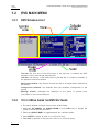

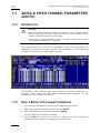

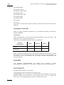

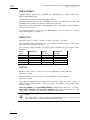
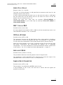


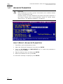
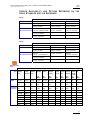
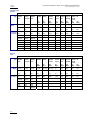
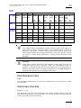
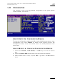


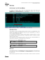
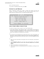

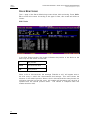


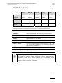


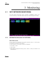
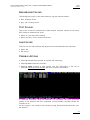
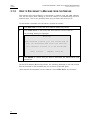

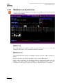
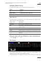
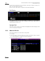
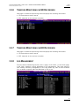
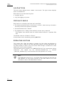
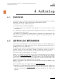


![2.8 conexión de varios servidores xt[2]](http://vs1.manualzilla.com/store/data/006305919_1-9948e093384d4040cdf0f68f445b7f43-150x150.png)


![XL[2] Technical Reference – Hardware](http://vs1.manualzilla.com/store/data/005956150_2-4515f3a1b925b4223206cf04092ab5bd-150x150.png)