1
After Sales Service Manual
Eurotech
466000076
ASKO
U.S.A.
ELECTRONIC FRONT LOADER WASHER
AND
COMBINATION WASHER/DRYER
WASHING MACHINE MODELS: ASKO WAM1712W
code 010477003
Eurotech EWF272EL
code 010477006
Eurotech EWF272ELGH code 010477007
WASHER DRYER MODELS:
1a EDIZIONE - JULY 2004
Eurotech EWC177W
ASKO WCAM1812
code 014477001
code 014477002
S.M.P.E.01.A
01-07-2004
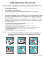
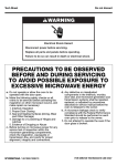
SAFE SERVICING PRACTICES
To avoid the possibility of personal injury and/or property damage, it is important that safe servicing
practices be observed, The following are examples, but without limitation, of such practices:
1.
Do not attempt a product repair if you have any doubts as to your ability to complete it in a
safe and satisfactory manner.
2.
Before servicing or moving an appliance:
. remove power cord from electric outlet, trip circuit breaker to OFF, or remove fuse.
. turn off water supply.
3.
Never interfere with the proper operation of any safety device.
4.
USE ONLY REPLACEMENT PARTS CATALOGED FOR THIS APPLIANCE. SUBSTITUTIONS
MAY DEFEAT COMPLIANCE WITH SAFETY STANDARDS SET FOR HOME APPLIANCES.
5.
GROUNDING: The standard color coding for safety ground wires is GREEN or GREEN with
YELLOW STRIPES. Ground leads are not to be used as current carrying conductors. IT IS
EXTREMELY IMPORTANT THAT THE SERVICE TECHNICIAN RE-ESTABLISH ALL SAFETY
GROUNDS PRIOR TO COMPLETION OF SERVICE. FAILURE TO DO SO WOULD CREATE
A POTENTIAL HAZARD.
6.
Prior to returning the product to service ensure that:
. all electric and water connections are correctly and securely connected.
. all water connections are tested for leaks.
. all electrical leads are properly dressed and secured away from sharp edges,
high-temperature components and moving parts.
. all uninsulated electrical terminals, connectors, heaters, etc. have adequate spacing from
all metal parts and panels.
. All safety grounds (both internal and external to the product) are correctly and
securely connected.
. all panels are properly and securely reassembled.
CAUTION:
When servicing a water using appliance in a location where the water supply has not
been in use for an extended time (such as vacation), open the hot water faucet at the
sink and allow the water to run for several minutes allowing water and accumulated
hydrogen gas to escape. Make sure there are no open flames (pilots) or cigarettes
near the faucet.
NO
YES
CLOSE
YES
NO
S.M.P.E.02.A
01-07-2004
IMPORTANT
This Service Manual must be used together with all the other technical documents appertaining to
the product itself (Exploded views, wiring diagrams and any other technical information provided).
Remove the plug from the mains power supply when
carrying out any operations on the machine.
RATING PLATE
The rating plate is located on the cabinet inside the main door on the front of the washing machine.
If the cabinet needs to be replaced, remove the rating plate from the cabinet itself and attach it to
the new one.
The rating plate reports all the nominal data required by current standards (power supply voltage,
total absorbed power, etc...).
The serial number consists of 11 characters that indicate the date of manufacture and serial number:
For example:
xxxW xxx
xxxx xxA
Model. .......
20042700001
xxxV xxHz
xxxx xxx xxxx xxx xxxx xxx
Manufacturers product
identification code
20042700001
{
}
}
4 digits number
denoting year of
manufacture (2004)
2 digits number
denoting the week
of manufacture
(week 27 of 2004)
5 digits denoting the
progressive number
of the product during
the week of manufacture
Should any problems occur with a washing machine, the Main Technical Assistance Office in your country must be
informed of the serial number and the model in question in order to help the manufacturer identify the product.
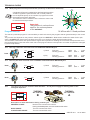
DESCRIPTION OF THE MACHINE
1 - Door filter
2 - Lint filter
3 - Adjustable leveling feet
4 - Drum
5 - Door handle
6 - Door
7 - Rating plate
8 - Scratch-resistant top
8
7
6
5
4
3
2
1
S.M.P.E.03.A
01-07-2004
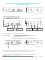
TECHNICAL DATAS
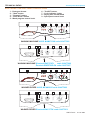
Control panel descriptions
ELECTRONIC CONTROL PANEL DESCRIPTIONS
1
2
3
4
5
6
7
8
9
- Detergent drawer.
- "Start" button
- "Prewash" button
- "Extra Rinse" button
- Wash program control knob.
1
- "On/Off" button.
- Cycle Indicator Lights
- Drying time control knob
- Spin speed control knob
2
3
4
START
PRE
WASH
EXTRA
RINSE
9
7
5
NO SPIN
1200
6
REGULAR
STOP
550
QUICK WASH
PREWASH
WHITES
WASH
1100
RINSE
700
COLOR
FAST
HAND
WASH
SPIN
COLOR
WOOL
STOP
800
1000
DELICATES
900
SYNTHETICS
PERMA
PRESS
WASHING MACHINE ASKO WAM1712W code 010477003
1
4 3 2
9
7
5
DELICATES
NO SPIN
START
PREWASH
REGULAR
STOP
SPIN
550
1200
6
HEAVY
STAIN
RINSE
WHITES
WASH
PRE
WASH
1100
COLOR
FAST
QUICK
WASH
RINSE
700
SPIN
COLOR
WOOL /
HAND WASH
STOP
1000
EXTRA
RINSE
800
COLOR
900
COLOR
FAST
ON
OFF
HEAVY
STAIN
SYNTHETICS
WASHING MACHINE Eurotech EWF272EL
code 010477006
Eurotech EWF272ELGH code 010477007
1
2
3
4
START
PRE
WASH
EXTRA
RINSE
8
20'
0'
40'
7
200'
PREWASH
/ WASH
180'
160'
80'
100'
120'
6
REGULAR
STOP
220'
60'
5
140'
DRY
WHITES
RINSE
DRY
STOP
COLOR
FAST
QUICK
WASH
SPIN
DELICATES
WOOL/ HAND
WASH
COLOR
PERMA
PRESS
SYNTHETICS
WASHER DRYER ASKO WCAM1812 code 014477002
1
4 3 2
8
20'
START
0'
7
5
DELICATES
DRY
140'
40'
130'
PREWASH/WASH
STOP
6
REGULAR
HEAVY
STAIN
SPIN
WHITES
RINSE
PRE
WASH
60'
120'
SPIN
COLOR
FAST
QUICK
WASH
DRY
110'
70'
EXTRA
RINSE
80'
90'
100'
STOP
COLOR
WOOL /
HAND WASH
COLOR
COLOR
FAST
ON
OFF
HEAVY
STAIN
SYNTHETICS
WASHER DRYER Eurotech EWC177W code 014477001
S.M.P.E.04.A
01-07-2004
TECHNICAL DATAS
ELECTRICAL CONNECTION
black
Check to make sure the main power supply and the outlet are appropriate
to support a 110/120 V, 15 amp single-phase circuit.
L
The power supply voltage is indicated on the rating plate inside the main
door of the washing machine.
green/yellow
Grounding Instructions
white
This appliance must be grounded. In the case of malfunction or breakdown,
N
grounding will reduce the risk of electric shock by providing a path of least
resistance for electric current. This appliance is equipped with a cord
having an equipment-grounding conductor and a grounding plug.
The plug must be plugged into an appropriate outlet that is properly
D100
installed and grounded in accordance with all local codes and ordinances.
WARNING!
Improper connection of the equipment-grounding conductor can result in a
risk of electric shock. Do not modify the plug provided with the appliance.
- Position the appliance so that the plug can be accessed and disconnected easily in case
of emergencies.
WATER SUPPLY
This washing machine can only be connected to the cold water supply system.
The water pressure must be between .05 MPa minimum and 1 MPa maximum.
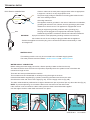
WATER SUPPLY CONNECTION
Before making the water supply connection, allow a quantity of water to flow from the top.
The water should be clean and free from impurities, especially where the system is new or has been left
unused for a length of time.
There are two hoses provided with the machine.
The hot water hose is indicated with a red strip running the length of the hose.
Insert the filter/washer supplied (Fig. 5) before connecting the water inlet hose to the valve.
Check that the other end of the hose is tight (Fig. 5A). Turn the supply valve on (Fig. 5B).
The drain outlet should be positioned at a height of between 23 (60 cm) and 35 (90 cm) above the floor (Fig. 6).
NOTE: To prevent siphoning, do not seal the drain hose connection into the drain outlet.
If the machine is not connected to a drain outlet, place the drain hose and bracket supplied
over the edge of a sink or wash basin and anchor it in place.
FIG.5A
close
open
FIG.6
Hot
Cold
FIG. 5
23,5' (60cm) minimum
35' (90cm) maximum
FIG.5B
S.M.P.E.05.A
01-07-2004
DSS
BP3
BP1
BP2
P11
PREH
L
N
P16
P14
DHE
fa
fa
HE
fa
fa
*** ***
***
AS
BLACK
AS2
AS5
T15
AS3
AS6
T17
T90
***
RF
***
***
10
12
cnF
1
TAB 10v.
BROWN
***
***
AWG-SILICON Wire
10 ways connector F
EVH
common
EVC
common
(F11) T90-RF
(F4)
S.M.P.E.06.A
LIGHT BLUE
IF
PRL
PRH
PREH
DSS
POT-TH
POT-VE
PROG
SONDA
TACHO
PS
EVH
EVC
NEUTRO
IN - BP3
FASE
P11
BLUE
(F1)
(F2)
(F3)
MOLEX 8Vie
MAIN
MOTOR
S TK
TR
S8
WHITE
ELECTRONIC
MOTOR
DRIVER
1 2 3 4
S
FILO DI TERRA
GROUND
GREY
Att-A
Att-B
DHE
HE
AS
T
CU
M
TM
PR
EVA
VA(C)
VA
VIOLET
cn1/cn2
LATO PISTE
Flat cable connection
cna/display
Flat cable connection
ORANGE
Washing Thermo-actuator A
Prewashing Thermo-actuator B
Drying Heating element
Washing Heating element
ON - OFF button
Klixon or Fixed thermostat
Control unit board
Main washing motor
Thermal cut-off
Re-cycle Pump Motor
Drying Water Valve
Drying Fan Motor Capacitor
Drying Fan Motor
Switch
Attuatore lavaggio
Attuatore prelavaggio
Resistenza asciugatura
Resistenza lavaggio
Pulsante On - Off
Termostato fisso
Modulo elettronico
Motore lavaggio
Protettore Termico Motore
Pompa di Ricircolo
Elettrovalvola Asciug.
Cond. Ventola Asciugat.
Ventola Asciugatura
4 ways con. S
Contro Unit
Interference filter
Low level pressostat
High level pressostat
Pressostat
Door safety catch
Variable Temperature Selector
Variable spin speed Selector
Programmer
Thermistor
Tachometer
Drain pump
Hot Water valve
Cold Water valve
RED
Filtro antidisturbo
Pressostato livello basso
Pressostato livello alto
Pressostato
Bloccoporta
Potenziometro temperatura
Potenziometro centrifuga
Programmatore
Termoresistenza
Tachimetrica
Pompa scarico
Elettrovalvola calda
Elettrovalvola fredda
RES. ASCIUG.
BP1
P14
(F6) (F5) RF
(F7)
S1
G
T TK
R
7 ways con. M
ASCIUG.
(F10)BP2-OUT
(F9)
ZS
ZR
ZN
ZL
AMP 6 Vie
MOTORE
12 ways connector B
(F12) RES.
(F8)
EVA
PS
1 2 3 4 5 6 7
EVC
Att-A
Common
Att-B
Common
EVL
Att-A
VA (BL3)
VA (BL2)
VA(C)
ELECTRONIC ZB
MOTOR
DRIVER ZT
Att-B
Z
Progr.
AMP 6Vie
Scheda SOLE
Pot-ve
VA(C)
VA (BL1)
Common
EVA
Common
EVA
SONDA
1 2 3 4 5 6 7 8 9 10 11 12
EVH
EXAMPLE OF ELETTRICAL DIAGRAM - COMBINATION WASHER/DRYER
Display
TECHNICAL DATAS
01-07-2004
DSS
BP3
BP1
BP2
P11
PREH
L
N
P16
P14
fa
fa
HE
fa
fa
AS2
AS5
RF
BLACK
AS3
AS6
T90
10
1
S.M.P.E.07.A
-
EVH
common
IF
PRL
PRH
PREH
DSS
POT-TH
POT-VE
PROG
SONDA
TACHO
PS
(F1)
(F2)
(F3)
(F4)
(F5)
(F6)
BLUE
RED
Interference filter
Low level pressostat
High level pressostat
Pressostat
Door safety catch
Variable Temperature Selector
Variable spin speed Selector
Programmer
Thermistor
Tachometer
Drain pump
LIGHT BLUE
Filtro antidisturbo
Pressostato livello basso
Pressostato livello alto
Pressostato
Bloccoporta
Potenziometro temperatura
Potenziometro centrifuga
Programmatore
Termoresistenza
Tachimetrica
Pompa scarico
NEUTRO
IN - BP3
FASE
BP1
P14
R
P11
(F9)
(F8)
S8
4 ways con. S
1 2 3 4
S
FILO DI TERRA
cna/display
GREY
Switch
VIOLET
cn1/cn2
Flat cable connection
ORANGE
LATO PISTE
Hot Water valve
Cold Water valve
Washing Thermo-actuator A
Prewashing Thermo-actuator B
Washing Heating element
ON - OFF button
Klixon or Fixed thermostat
Control unit board
Main washing motor
Thermal cut-off
Flat cable connection
Elettrovalvola calda
Elettrovalvola fredda
Attuatore lavaggio
Attuatore prelavaggio
Resistenza lavaggio
Pulsante On - Off
Termostato fisso
Modulo elettronico
Motore lavaggio
Protettore Termico Motore
WHITE
EVH
EVC
Att-A
Att-B
HE
AS
T
CU
M
TM
Control Unit
7 ways con. M
12 ways connector B
(F10) BP2-OUT
(F7)
MOLEX 8Vie
S TK
TR
S1
G
T TK
R
EVA
ZR
ZS
ZT
ZL
ZN
1 2 3 4 5 6 7
EVC
Att-A
Common
Att-B
Common
1 2 3 4 5 6 7 8 9 10 11 12
EVH
AMP 6 Vie
MOTORE
Att-B
EVL
Att-A
ZB
Z
Pot-ve
AMP 6Vie
Scheda SOLE
PS
SONDA
EVC
common
(F11) T90
(F12)
BROWN
10 ways connector F
Progr.
EXAMPLE OF ELETTRICAL DIAGRAM - WASHING MACHINE
Display
TECHNICAL DATAS
01-07-2004
TECHNICAL DATAS
1.
WASHER MODELS:
ASKO WAM1712W
code 010477003
Eurotech EWF272EL code 010477006
Eurotech EWF272ELGH code 010477007
- 11 programs with various other combinations
COMBINATION WASHER DRYER MODELS:
Eurotech EWC177W code 014477001
ASKO WCAM1812
code 014477002
- 11 washing programs and 2 drying programs.
2.
Dimensions
Height
Width
Depth
Depth w/door open:
3.
General specifications
Voltage/ Frequency
Fuse
4.
Drum volume
65 liters
5
Drum speed
Slow spin
High speed spin
550 rpm.
according to the model
6
Load capacity
Washing COTTONS
Washing SINTHETICS
Washing WOOL
Drying COTTONS
Drying SINTHETICS
max. 7,0 kg dry laundry
max. 3,5 kg dry laundry
max. 1,5 kg dry laundry
max. 5,0 kg dry laundry
max. 3,0 kg dry laundry
33 -1 / 4"
23 -3 / 8"
23 -1 / 8"
38 - 3/4"
= 84.45 cm
= 59.37 cm
= 58.74 cm
= 98.43 cm
110/120 Volts - 60 Hz
15 Ampères
7. Description of electrical components
7.1
Tubular wash heating element with internal fuse
RF
HE
7.2
Power rating
1150 W
Voltage
120 V
Warning: the Blue contact indicates the thermofuse
G140
Tubular dry heating element (only for combination washer/dryer)
RA1
RA1
DE1
7.3
H120
Synchronous drain pump
PS
F010
DPM
PS
7.4
1400 W
120 V
Power rating
Flow rate
Height of drain hose
Height of the drain hose
approx. 30 W
20 - 25 l/min
approx. 2800 rpm
max. 90 cm
= 35"
min. 60 cm
= 23"
When a washing or drying cycle is in progress, a safety device
prevents the door from being opened. To open the door while
a wash program is running, switch off the washing machine
using the On/Off button. The door can then be opened after a
time lapse of approximately 2 minutes.
Safety door catch
DSS
BP1
BP3
Power rating
Voltage
NEVER OPEN THE DOOR IF THE WATER LEVEL IS VISIBLE
THROUGH THE DOOR GLASS.
BP2
E060
At the end of the cycle, wait for the END indicator light to
flash before opening the door.
S.M.P.E.08.A
01-07-2004
TECHNICAL DATAS
7.5
Drying motor capacitor (H019)
(only for combination washer/dryer)
4 µF 450Volts
C
or
7.6
VA(C)
H019
Drying motor (H290)
(only for combination Washer/Dryer)
2 poles
Type
Class F
Isolation
approx. 140 W
Max. absorbed power
Voltage (according to the model) 120V - 60 Hz
approx. 2800 rpm
Anticlockwise speed Rotation
7.7
H290
Fixed thermostats
A-
For washer and Combination washer/dryer:
Automatic reset 90°C fixed safety thermostat.
Normally Closed for a wash.
G560
TH90°
B-
For washer and Combination washer/dryer:
Thermistor (temperature sensor for water in the tub
TR
TH
TH
C06
C 05
The thermistor checks the temperature of the water in the tub, to read
between 0°C and 90°C (32°F and 194°F) with a tolerance of + / - 2°C
(5°F). As soon as the water's temperature increases, the resistance in
the thermistor decrease.
The heating element will not work if the thermistor is in short-circuit or
disconnected from the electronic circuit board.
G005
Some thermistor values :
Water Temperature F° (C°)
Resistance in kOhm
C-
68° (20°)
86° (30°)
104° (40°)
122° (50°)
140° (60°)
6,06
4,12
2,81
1,99
1,42
T150°
(only for combination washer/dryer)
T150°C long bulb fixed thermostat with automatic reset
Normally Closed Contact, controls the drying temperature.
H220
S.M.P.E.09.A
01-07-2004
TECHNICAL DATAS
D-
8.0
(only for combination washer/dryer)
Half inch fixed safety thermostat with manual reset.
Normally Closed Contact.
Intervenes only if there is a fault in the 150°C drying thermostat or
in the fan and drying unit.
H370
T170°
S17
S17
Pressure switch
D020
Washing machine fill levels.
The electronic control unit calculates the washing machine fill levels according to the type and
quantity of washing placed in the tub and the set program, and then adds a safety margin which
is pre-programmed in the control unit software.
PREH
P14
P12
P11
The single level pressure switch is used with the following functions:
P11-P14
- Signals the electronic control unit (open/closed) that the low water level has been reached.
- Heater element safety switch.
The pressure switch has only 1 level that is identified in the legend with the letters (BL).
The contact P16 is the safety overflow that intervenes when too much water enters tub
interupting the power supply to the inlet valve and putting the drain pump in operation of draining
the water.
P16
FILLING PROCESS
AAL
AL
= 15L (3.9G)
= 13L (3.4G)
BL
= 7,5L (1.9G)
Note: The below is only an example of the filling process
40"
BL
AL
AAL
70"
80"
TIME - seconds
(7,5litri) = 40" = Time to reach the first level ( by pressure switch )
(13litri) = 40"+30" - with Maximum safety time 45" = P + 3/4 of the necessary time to reach BL
(15litri) = 40"+40" - with Maximum safety time 60" = P x 2 of the necessary time to reach BL
In the microprocessor of the electronic module, there is a safety check for the maximum time of the water filling.
Should the first water level of the machine requires too much time due to very low pressure and the water pressure
suddenly increase the water amount in an overfilled way, the AAL safety will intervene.
NB:
Every time the machine fills with water, the time to reach the first level is checked.
To have the correct different levels, the BL must be reached within 60 seconds.
Pressure switch
Program
Selector
Water fill principle for
electrical machines
Solenoid valve
Electronic control unit
S.M.P.E.10.A
01-07-2004
TECHNICAL DATAS
9.0
Main power supply switch:
AS3
AS6
AS2 AS3
AS2
AS5
AS5 AS6
Start/Stop
10.0
Washer ASKO WAM1712W
Washer Eurotech EWF272EL
Washer Eurotech EWF272ELGH
Combination Washer/Dryer EUROTECH EWC177W
Combination Washer/Dryer ASKO WCAM1812
Ref. 010477003
Ref. 010477006
Ref. 010477007
Ref. 014477001
Ref. 014477002
Description of the functions of the switch:
Start/Stop switch
Switches the power supply to the washing machine on
or off.
2 NORMALLY OPEN
CONTACTS
Logarithmic Potentiometer 50 kOhm with 8 fixed positions for spin speed selection
used on:
Washer ASKO WAM1712W
Ref. 010477003
Washer Eurotech EWF272EL
Ref. 010477006
Washer Eurotech EWF272ELGH Ref. 010477007
NO SPIN
550
1200
Pot-ve
1100
700
Simbol on wiring diagram
1000
800
900
When the drying time is set with the knob, the Led "DRY"remain activated until the button Start is pushed ON.
The Drying function could be activated only for the Cotton, Synthetics and Quick wash programmes.
Spin speed setting knob
The knob allows the maximum spin speed to be modified and/or reduced to zero.
The set spin speed is displayed by the LCD or by the leds above the button.
The initial speed setting displayed is the maximum allowed for the set program.
The spin speed can also be modified during the wash cycle.
NB: For combination Washer/Dryer:
Excluding the spin also excludes the DRYING function.
11.0
Logarithmic Potentiometer 36 kOhm with 12 fixed positions for drying time selection
used on: Combination Washer/Dryer EUROTECH EWC177W Ref. 014477001
Combination Washer/Dryer ASKO WCAM1812
Ref. 014477002
20'
PREWASH/WASH
0'
140'
40'
130'
RINSE
Pot-ve
Simbol on wiring diagram
SPIN
60'
120'
DRY
STOP
110'
70'
80'
90'
100'
S.M.P.E.11.A
01-07-2004
TECHNICAL DATAS
12.0
Wash program selection potentiometer (used only on Electronic machines).
Combination Electronic washer/driers are fitted with a positive
36 kOhm logarithmic potentiometer with 12 fixed positions.
Its use depends purely on the number of programs for which
the appliance has been designed.
The maximum Ohmic resistance is the reference value used
to start the Autotest procedure.
Important:
The positions in red are those
used for the various phases
of the autotest.
Progr.
6
STOP
5
7
4
8
9
3
2
10
1
11
12
36 kOhm with 12 fixed positions
Program selector.
The start of a particular program is commanded by a wash code sent by the program selector (potentiometer) to the control
unit.
The process also depends on the pressure switch signal: an OPEN P11 - P14 contact enables the water feed or spin,
while a CLOSED P11 - P14 contact enables the motor to run during the wash and the heating phase.
The thermistor, tachometric and optional button signals are important for enabling the control unit microprocessor to run
the required program. Note that each wash code of the program selector corresponds to a number of operations managed
by the microprocessor.
13.0
Two way cold water solenoid valve forCombination Washer/Dryers.
EVC
WVC
D010
EVC
EVA
13.1
EVH
MAX.
MIN.
12
0,05 - 1
l / min
MPa
2) Dry
Flow rate:
Working pressure:
MAX.
MIN.
0.35
0,05 - 1
l / min
MPa
WVW
Flow rate:
Working pressure:
MAX.
MIN.
7
0,05 - 1
l / min
MPa
Flow rate:
Working pressure:
MAX.
MIN.
10
0,05 - 1
l / min
MPa
1) Wash
EVH
One-way cold water solenoid valve used only for Washers.
D010
14.0
Flow rate:
Working pressure:
One-way hot water solenoid valve for Washer and Combination Washer/Dryers.
D300
13.2
1) Wash
EVC
WVC
1) Wash
EVC
Cold plug type thermo-actuators with 220-240 V 50 Hz power supply for feeding water to the
detergent dispenser:
Actuator
A
Actuator
B
THERMOACTUATOR
B
THERMOACTUATOR
A
Description of water distribution during a wash cycle
PREWASH PHASE:
WASH PHASE:
CONDITIONER PHASE:
Both thermo-actuators are inactive.
During the drain phase, thermo-actuator A is active.
Thermo-actuator A is active.
Thermo-actuator B is active.
S.M.P.E.12.A
01-07-2004
TECHNICAL DATAS
Water fill principle
At the start of the wash program, the control unit, according to the program selected, commands the solenoid valve to
feed water to the appliance providing the pressure switch authorises the action (the pressure switch must be OFF).
When the required water level has been reached, the control unit closes the solenoid valve.
If the pressure switch detects excess water entering the appliance, it sends a signal to the control unit which then starts
the drain pump.
Heating phase principle
The heater element switches on when pressure switch contact P11-P14 is closed (water in the tub).
A traditional thermostat to interrupt the power supply to the heater element is not provided.
The control unit receives the Ohmic value of the resistance and switches off the heater element when the correct
temperature has been reached.
In the case of a fault in the heater element and/or thermistor, a maximum heating time of 30 minutes for each heating
phase is provided. Should a fault of this type arise, the washing machine will complete a cold wash program though will
take more time.
Heating phase principle for
electronic washers
The heating element begins
working, when the contact
P11-P13 of the pressure switch
they is closed.
B003
A210
Drying
Selector
B022
Programmes
Selector
On/Off
switch
G005
Main
Elettronic
P.C.B.
Thermistor
A044
black
green/yellow
white
L
D060
TH90°
N
Fuse
G140
Motor
P.C.B.
HE
RF
D100
G560
Thermostat 90°C
Heating Element
G610
D020
Pressure Switch
G130
Motor and
Tachometer
COOLING
The cooling phase is necessary in order to ensure that the water pumped to the drainage system is not too hot.
This is always carried out for the COTTON program if the temperature is higher than 70°C. The water is gradually cooled
down by allowing cold water to enter after the last wash cycle and before draining. The control unit feeds the cold water
for one minute, pauses one minute then drains.
During DELICATE and SYNTHETIC programs, the cooling is always carried out before draining by activating the solenoid
valve for 10 seconds.
WASH LOAD BALANCE CONTROL
The washing machines are fitted with an electronic balance control which is active in all the spinning phases.
At the start of the spin cycle, the load balance is checked by the control unit. If the load in the drum is unbalanced, the
washing machine attempts to start the spin a number of times. If the control unit detects that the load is very unbalanced,
the entire spin cycle may last as long as 20 minutes (even if the display still shows 12' (minutes).
S.M.P.E.13A
01-07-2004
TECHNICAL DATAS
15.0
Main Motor
Asincronous 3 phases with tachometer
115V - 60 Hz
G130
MOTOR TERMINAL BOARD
AMP 6 ways
connector
R
G
G610
T TK
S TK
DATAS VALID FOR ALL MOTORS
Tachymeter generator
Tolerance for winding measurement
Note:
16.0
TK-TK 29 Ohm+/- 0,5 Ohm
+/- 0,5%
There may be slight variations in ohmic resistance between motors produced by different
manufacturers.
See also motor nominal data identification plate.
Motor Control Unit
S1
MOLEX 8 way connector S
A044
115v - 60Hz.
S2
S3
S4
S5
S6
S7
S8
AMP 6 way connector Z
ZL
ZN
ZB
ZT
ZS
ZR
to the Motor Tachometer (TK)
to the Motor Tachometer (TK)
to the Main Control Unit - Connector M (CM3)
to the Main Control Unit - Connector M (CM1)
to the Main Control Unit - Connector M (CM5)
to the Main Control Unit - Connector M (CM4)
to the Main Control Unit - Connector M (CM3)
to the Main Control Unit - Connector F (CF10)
to the Main Control Unit - Connector F (CF4)
to the Main Motor - Earth wire(G)
to the Main Motor - Wire (T)
to the Main Motor - Wire (S)
to the Main Motor - Wire (R)
S.M.P.E.14.A
01-07-2004
TECHNICAL DATAS
15.0 Electronic control unit contacts
1
(F1)
Electronic washers
- version with 2 thermo-actuators
10 ways connector F
(F2)
10
12
(F3)
(F4)
(F5)
(F6)
(F7)
(F8)
(F9)
FASE
IN - BP3
NEUTRO
P11
RF
PCB Contacts
P14
BP1
RES. ASCIUG.
(F11)
BP2-OUT
T90-RF
(F12)
RES. ASCIUG.
(F10)
not used for washing machines
not used for washing machines
12 ways connector B
1 2 3 4 5 6 7 8 9 10 11 12
FUNCTIONS OF CONTACTS
F1
F2
F3
F4
F5
F6
F7
F8
F9
F10
F11
F12
B1-B3
B1-B2
B4
B5
B6
B7-B8
B9
B10
B11
B12
7 ways con. M
1 2 3 4 5 6 7
4 ways con. S
1 2 3 4
Flat cable connection
Cn1 - SCHEDA DISPLAY
receives power from the ON-OFF button
feeds door catch contact BP3
current output to ON-OFF button
feeds pressure switch contact P11
feeds the heater element through the internal safety thermo-fuse
--------------receives the pressure switch level reached signal from contact P14
feeds door catch contact BP1
receives the return signal from the drying heating element through safety thermostat T170°C which, when the
temperature is reached, opens the contact - used only for combination washer/dryer.
feeds door catch contact BP2
receives the return signal from the washing heating element through safety thermostat T90°C which, when the
temperature is reached, opens the contact
receives the return signal from the drying heating element through thermostat T150°C which, when the
temperature is reached, opens the contact - used only for combination washer/dryer.
feeds Hot Water Solenoid Valve EVH
feeds Cold Water Solenoid Valve EVC
common Thermo-actuator A and Thermo-actuator B
power supply Thermo-actuator A (Wash)
power supply Thermo-actuator B (Softener)
power supply Drain pump
return signal from pressure switch overfill safety (P16), starts the pump.
common Drying Water Solenoid Valve (EVA) and Drying Fan Motor (VA-BL1) - not used for washer.
power supply Drying Water Solenoid Valve (EVA) - not used for washer.
power supply Drying Fan Motor (VA-BL2) and Drying Fan Motor Capacitor (VA-C) - not used for washer.
M1-M2-M3-M4-M5
power supply Motor
M6-M7 return signal from thermistor
S1-S2 receives signal from program selector potentiometer.
S3-S4 receives signal from spin speed potentiometer (Washer) or from drying time potenziometer (Washer/Dryer)
Flat cable receives information from the pushbutton circuit board (wash options).
IMPORTANT:
Before replacing the control unit, use the AUTOTEST to ensure that the electrical components are in
working order, that the contacts of the control unit connections are good and that the mains voltage
is within the required limits.
S.M.P.E.15.A
01-07-2004
Pushbutton specifications
Description of the functions of the selector buttons:
Start button
This button confirms the previously set functions and starts the program.
The button is not normally lit, but lights up to indicate the cycle is running only if the door catch is
closed.
When the program selector is positioned on "Stop", the cycle is stopped and the button light flashes.
Prewash button
This button includes or excludes the prewash (see specifications) from the wash programs that accept
the function (see table).
The button is not normally lit but lights up when the function has been selected.
Extra rinse button
This button includes or excludes the extra rinse (see specifications) from the wash programs that
accept the function (see table).
The button is not normally lit but lights up when the function has been selected.
CONTROL PANEL
Program and Temperature selector knob
This knob is used to select the type of wash and the most appropriate temperature for the items to
be washed.
Positioning the knob at the "STOP" position will reset the program.
If, for any reason, you want to change the set wash program or add more washing to the load during
the wash cycle, simply place the programmer knob on STOP. Then re-position the knob on the
new program and press the START button.
At this point, before the program restarts, any water in the machine will be drained.
N.B. After carrying out this operation, check that there is detergent in the appropriate compartment
---- and add if necessary.
Warning:
Only use this function if strictly necessary and then only if the program to reset has
been running for less than 3 minutes. Before opening the door after a reset, wait 2
minutes for the locking mechanism to release.
S.M.P.E.16.A
01-07-2004
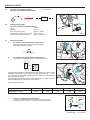
466000001-1-UK
07/03/2003
MANUAL SELF-TEST OF CIRCUIT BOARDS ON MODEL MINI-SEL
with 2 knob control panels
START
PRE
WASH
EXTRA
RINSE
NO SPIN
1200
STOP
550
PREWASH
QUICK WASH
REGULAR
700
RINSE
COLOR
FAST
HAND
WASH
SPIN
800
1000
STOP
COLOR
WOOL
DELICATES
900
STOP
SPIN
550
1200
PREWASH
REGULAR
HEAVY
STAIN
RINSE
WHITES
WASH
WASH
1100
DELICATES
NO SPIN
START
WHITES
PERMA
PRESS
PRE
WASH
1100
700
COLOR
FAST
QUICK
WASH
RINSE
SPIN
EXTRA
RINSE
COLOR
WOOL /
HAND WASH
STOP
1000
800
COLOR
900
SYNTHETICS
COLOR
FAST
ON
OFF
HEAVY
STAIN
SYNTHETICS
START CONDITIONS FOR MANUAL SELF-TEST
- Set the Programmer Knob at 6-o-clock position.
- Set the Spin Speed Knob at 9-o-clock position.
- Keep the PREWASH Button pressed and at the same time switch the machine on by pressing the On/Off button.
ON
START
PRE
WASH
EXTRA
RINSE
NO SPIN
1200
STOP
550
PREWASH
QUICK WASH
REGULAR
700
RINSE
STOP
800
COLOR
WOOL
DELICATES
900
STOP
SPIN
550
1200
PREWASH
REGULAR
HEAVY
STAIN
RINSE
WHITES
WASH
COLOR
FAST
HAND
WASH
SPIN
1000
DELICATES
NO SPIN
START
WHITES
WASH
1100
ON
PERMA
PRESS
PRE
WASH
1100
700
COLOR
FAST
QUICK
WASH
RINSE
SPIN
EXTRA
RINSE
800
COLOR
900
SYNTHETICS
Cycle
Spin Speed
Programmer
Potentiometer at Indicator Potentiometer
Lights
9-o-clock
at 6-o-clock
COLOR
WOOL /
HAND WASH
STOP
1000
COLOR
FAST
ON
OFF
HEAVY
STAIN
SYNTHETICS
Cycle
Indicator
Lights
Spin Speed
Potentiometer at
9-o-clock
Programmer
Potentiometer
at 6-o-clock
The five LEDS indicating the "Cycle Indicator Lights" will LIGHT UP.
THE TEST CHECKS
- The Temperature Probe (THERMISTOR)
- The OFF position of the Pressure Switch (no water in tub)
- The door catch interlock
If the results of these checks are positive, the top LED will switch off.
START
PRE
WASH
EXTRA
RINSE
NO SPIN
1200
STOP
550
PREWASH
QUICK WASH
REGULAR
700
RINSE
COLOR
FAST
HAND
WASH
SPIN
800
1000
900
STOP
SPIN
550
1200
PREWASH
STOP
REGULAR
HEAVY
STAIN
RINSE
WHITES
WASH
WASH
1100
DELICATES
NO SPIN
START
WHITES
COLOR
WOOL
DELICATES
PERMA
PRESS
PRE
WASH
1100
700
RINSE
COLOR
FAST
QUICK
WASH
SPIN
EXTRA
RINSE
STOP
1000
800
COLOR
WOOL /
HAND WASH
COLOR
900
SYNTHETICS
COLOR
FAST
ON
OFF
HEAVY
STAIN
SYNTHETICS
The luminous buttons change their status from On to Off or vice versa, each time they are pressed.
The only exception is the START button which only lights up while it is being pressed.
At this point, the test can be continued using the programmer knob as explained
in chapter MANUAL TEST SELECTION
S.M.P.E.17.A
01-07-2004
DIAGNOSTICS TABLE
The electronic control unit also allows individual components to be tested by varying the knob setting and maintaining the
other conditions unchanged.
Once the autotest function has been started, the required test can be selected by placing the knob in the appropriate
position. Each position of the knob corresponds to a component test.
Starting from the start position (6-o-clock) and rotating the knob anticlockwise one position at a time there are six
tests that can be carried out. Except for the first test, which is carried out by the control unit itself, in order to verify
the result of the test, the behaviour of each tested component must be monitored..
The control unit takes a few seconds to pass from one test to the next. The acceptance of the test is signalled by the
leds or by a display code indicating the program corresponding to the position of the knob in autotest. From this
point on, all the suspect components can be tested.
The correspondence between the reference position of the knob and a wash program is purely indicative, in that this
is linked to the appliance model in question.
Led
Position
on
of knob
SUMMARY TABLE
light
index mark
Test 1
PREWASH/WASH
- Start position, all the functions are deactivated.
6-o-clock
position
RINSE
The control unit automatically tests the operation of the thermistor, the
pressure switch OFF condition (no water in tub), the program selector and
the door catch closed condition.
SPIN
DRY
STOP
Test 2
1
- Fills with water through the cold solenoid valve until the pressure switch trips in.
- Actuator A and actuator B are OFF (water enters the prewash detergent dispenser)
2
This procedure tests the operation of the cold water solenoid valve and the
pressure switch.
Test 3
Test 4
- The heater element is activated (only with water)
- The motor rotates alternately in both directions (45 revolutions clockwise, pause,
45 revolutions anticlockwise).
- Thermo-actuator A only is activated (water enters the wash compartment).
This procedure tests the operation of the following components:
- heater element; wash motor and thermo-actuator A.
3
N.B.: In Autotest, the No Spin function is disabled.
- The drain pump is activated and the spin runs at the preset speed.
- Thermo-actuator B only is activated (water enters the softener compartment)
4
This procedure tests the operation of the following components:
- drain pump, spin motor and thermo-actuator B.
Test 5
- 10 fill with hot water solenoid valve where fitted (with level pressure switch off)
wash motor rotation with different rpm and direction according to the circuit
board model.
- Actuator A and actuator B are ON (water enters the softener dispenser)
This procedure tests the operation of the hot water solenoid valve (where fitted and
only with pressure switch OFF) and the wash motor.
5
Test 6
6
This procedure tests the operation of the following components:
- drying solenoid valve.
- drying fan motor
- drying heater element
S.M.P.E.18.A
01-07-2004
DIAGNOSTICS TABLE
TROUBLESHOOTING GUIDE
Before carrying out any operations on a component check the quality of the electrical connections to the electronic control
unit.
Check the condition of the wiring harness (for wear, twists, breakages) and the connections.
Always check that the contacts of the connections on the electronic control unit are tight.
Always start by checking the other components involved, and then check the electronic control unit last.
The program will not start.
Try to start the manual autotest, if the control unit does not enter autotest mode, check the connections on the control unit
itself. If the connections are good, replace the control unit.
In the case where the autotest is effected, wait until the top wash program led switches off. If this does not happen, then
the control unit has discovered a fault in one of the three components under test:
-the door catch
- the pressure switch
Status of Position of
- the thermistor.
knob index
the
wash phase mark
The door catch does not close the contact.
leds
- Check that the connections have been properly made.
- Use a Tester to check the voltage between contact BP3 and BP1. If there is no voltage:
- Check that power is arriving at the control unit. If there is no power, find out why.
6-o-clock position
- If there is power arriving at the control unit but there is no current at the door catch, use a
Tester to check whether there is voltage at the outputs of the control unit to the door
catch. If there is no voltage, replace the control unit.
- If there is power between contact BP3 and contact BP1, replace the component.
If the door catch closes properly, check the pressure switch.
Disconnect the pressure switch from the wiring and retest. If the test is ok, replace the
component, otherwise if the problem persists:
- Check that the connections have been properly made.
- Check that the pressure switch pipe and the compression chamber are not blocked.
- Disconnect the wiring from the thermistor, fit a new thermistor that is known to be working.
Retest and if ok replace the component (the test is only valid if the washing machine is cold).
If the thermistor is working, replace the control unit.
1
Water does not enter the tub
Check that the water feed valve to the washing machine is open.
Put the control unit in Autotest mode as described previously. Carry out Test 2 of the manual autotest
procedure (testing the solenoid valve), The tests starts when the leds switch off:
6-o-clock position
minus one
- Use a Tester to check the voltage at the ends of the wires connecting the solenoid valve
to the control unit.
- Use a Tester to check the continuity between the two contacts of the solenoid valve, if
the circuit is open replace the component.
- If all the above tests result positive, replace the control unit.
1 2
The washing machine does not heat the water in the tub.
Put the control unit in Autotest mode and carry out Test 2 to allow water to enter the tub
(this is required for the heater element to function).
With water in the tub, carry out Test 3 of the manual Autotest. Wait until the leds switch on
(the washing machine is in Autotest mode) to test the heater element:
6-o-clock position
minus two
- Use a Tester to check the continuity between the two contacts of the heater element,
if the circuit is open replace the component.
- Use a Tester to check the continuity at the ends of the wires connecting the heater
element to the control unit.
- Use a Tester to check the continuity between the two contacts of the T90° safety
thermostat, if the circuit is open replace the component.
- If all the above tests result positive, replace the control unit.
S.M.P.E.19.A
1 2
3
01-07-2004
DIAGNOSTICS TABLE
The motor does not turn properly during a wash and/or spin
Put the control unit in Autotest mode and move the programmer knob to the Test 4 position. Wait
for the leds to light up (the washing machine is in Autotest mode) and then test the motor. If the
motor does not run properly:
6-o-clock position
minus three
- Disconnect the motor from the wiring terminal board.
- Use a Tester to check the continuity at the ends of the wires connecting the wiring terminal
board to the control unit and check that the connectors are not damaged or dirty.
- Replace the control unit with one known to be in working order and check that the motor
runs. If the motor runs replace the control unit, otherwise replace the motor.
1 2
3
4
The washer/drier does not drain
6-o-clock position
minus three
Check that the washer/drier filter or the users drains are not blocked.
Put the control unit in Autotest mode and move the programmer knob to the Test 4 position.
Wait for the leds to light up (the washer/drier is in Autotest mode) and then test the pump:
- remove the wires from the pump and check the continuity between the two terminals
of the drain pump itself.
- if the circuit is open, replace the pump.
- if the circuit is closed, remove the pump from the washing machine and use a
screwdriver to check for any foreign bodies in the scroll.
- use a tester the check the continuity in the pump power supply wires. If the tests prove
negative replace the control unit.
1 2
3
4
Water flows into the tub continuously.
Check that the solenoid valve is working by carrying out the appropriate autotest for that particular component.
- Check that the pressure switch is working by carrying out the appropriate autotest for that particular component.
- Check that there are no leaks from the tub unit.
- Remove the pressure switch pipe from the drain coupling and check that there are no holes in the pipe.
- If all the above tests result negative, replace the control unit.
SAFETY
After eight failed attempts to start the motor (either in wash or spin mode), the control unit passes to the end of the cycle
and the End indicator light flashes. (motor rotor blocked or tachometric open).
If the control unit does not detect the pressure switch empty condition after twenty minutes of pump running time, it passes
to the next step. (Pump blocked).
If, after fifty minutes of heater element operation the set temperature has not been reached, the control unit advances
and continues the cycle as normal.
S.M.P.E.20.A
01-07-2004