1
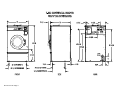
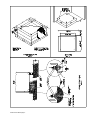
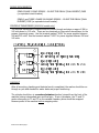
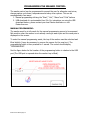
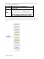
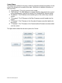
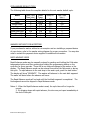
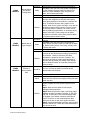
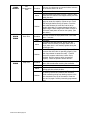
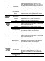
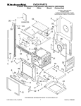
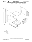
COMMERCIAL WASHER
MODEL T-300 VENDED
C-SERIES CONTROL
OPERATOR’S MANUAL
INSTALLATION & OPERATION
INSTRUCTIONS
Please read this information and retain for reference.
WARNING - THIS WASHER IS EQUIPPED WITH DEVICES AND FEATURES RELATING TO ITS SAFE
OPERATION. TO AVOID INJURY OR ELECTRICAL SHOCK, DO NOT PERFORM ANY SERVICING UNLESS
QUALIFIED TO DO SO.
IT IS THE RESPONSIBILITY OF THE OWNER TO CHECK THIS EQUIPMENT ON A FREQUENT
BASIS TO ASSURE ITS SAFE OPERATION.
A machine should not be allowed to operate if any of the following occur:
- Excessively high water level.
- If machine is not connected to a properly grounded circuit.
- If the door does not remain securely locked during the entire cycle.
- Vibration or shaking from an inadequate mounting or foundation.
WARNING - FOR SAFETY
1.
2.
3.
4.
5.
6.
Always shut off power and water supply before servicing.
Do not overload the washer.
Do not open door when cylinder is in motion or it contains water.
Do not bypass any safety devices of this washer.
Do not use volatile or flammable substances in or near this washer.
Keep all panels in place. They protect against shock and injury and add rigidity to the washer.
PREVENTIVE MAINTENANCE REQUIREMENTS
DAILY
- Check that the loading door remains securely locked and cannot be opened during the entire cycle.
- Check the water connections for leaks.
- Clean the top and sides of the cabinet to remove residue.
- Clean the soap dispenser and lid and check that all dispenser mounting screws are in-place and tight.
- Check the drain valve for leaking and that it opens properly.
- Check the loading door for leaks. Clean the door seal of all foreign matter.
- Leave the loading door open to aerate the washer when not in use.
QUARTERLY
- Make sure the washer is inoperative by switching off the main power supply.
- Check the V-belts for wear and proper tension.
- Clean lint and other foreign matter from around motor.
- Check all water connections for leaks.
- Wipe and clean the inside of the washer and check that all electrical components are free of moisture
and dust.
- Remove and clean water inlet hose filters. Replace if necessary.
- Check anchor bolts - retighten if necessary
IMPORTANT: Replace any and all panels that were removed to perform daily and/or quarterly
maintenance.
8514-223-001 REV B page 1
TABLE OF CONTENTS
Washer Specifications
Mounting Dimensions
Installation Instructions
Operating Instructions
Programming the Washer Control
Displayed Washer Faults
Servicing and Troubleshooting
Accessories and Contact Information
Page No.
2
3
4
8
10
24
30
34
WASHER SPECIFICATIONS
MODEL
T-300 20 LB. WASHER
CAPACITY
20 LBS/2.7 CUBIC FT. (9.1 kg/76.5L)
CYLINDER SIZE
21” DIA X 13 1/2” DEEP (53cm X 34cm)
ELECTRICAL
208-240 VAC, 60 HZ, 1 OR 3 PHASE or 120 VAC, 60 HZ, 1 PH
DRIVE SYSTEM
SOFT START REVERSING INVERTER DRIVE, 1 HP MOTOR
WASH SPEED
55 RPM
INTERMEDIATE
EXTRACT
449 RPM (60 G’S)
FINAL EXTRACT
579 RPM (100 G’S)
MACHINE CONTROL
PROGRAMMABLE COMPUTER
WATER INLET
2 SOLENOID OPERATED VALVES
FLOW RATE: 9 GAL/MIN EACH, 30-120 PSI
DRAIN VALVE
2 1/4” DIAMETER (5.7 cm)
8514-223-001 REV B page 2
8514-223-001 REV B page 3
INSTALLATION INSTRUCTIONS
All washers must be installed in accordance with all local, state and national
building, electrical, plumbing and other codes in effect in the area.
WARNING - THESE INSTALLATION AND SERVICING
INSTRUCTIONS ARE FOR USE BY QUALIFIED PERSONNEL ONLY.
TO AVOID INJURY AND ELECTRICAL SHOCK DO NOT PERFORM
ANY SERVICING OTHER THAN THAT CONTAINED IN THE
OPERATING INSTRUCTIONS, UNLESS QUALIFIED.
FOUNDATION REQUIREMENTS
This machine is designed for use on or over bare concrete floor - not to be used above
combustible flooring. The washer must be securely bolted to a substantial concrete
floor, or mounted upon a suitable base that is securely bolted to a substantial concrete
floor. CARE MUST BE STRESSED WITH ALL FOUNDATION WORK TO INSURE A STABLE
UNIT INSTALLATION, ELIMINATING POSSIBILITIES OF EXCESSIVE VIBRATION. All
installations must be made on sound concrete floors, 6 inches (150mm) or thicker.
Anchor bolts or expansion anchors must be of a quality grade and a minimum of ½ inch
(14 mm) diameter.
MOUNTING
A concrete pedestal or steel-mounting base that elevates the machine approximately 8
inches (200 mm) above the floor level is recommended to provide easy access to the
loading door. Allow a minimum of 24 inches (600mm) of clearance behind the rear of
the machine, to provide access for motor removal. Refer to Fig. 1-1 and 1-2 for
machine bolt-down dimensions.
If an elevated concrete pedestal is desired, it should be embedded into the existing
floor. Anchor bolts should be 1/2" x 8" (14 mm x 200 mm), grade 5 or better, headed
by a 4 inch (10 cm) square fish plate and should protrude 1 7/8” (48 mm) above the
finished surface of the pedestal. EXPANSION ANCHORS ARE NOT RECOMMENDED FOR
USE IN CONCRETE PEDESTALS, BECAUSE THE ANCHORS ARE TOO CLOSE TO AN
EDGE, CAUSING IT TO BREAK OUT. (See Fig. 1-1 and 1-3.)
8514-223-001 REV B page 4
8514-223-001 REV B page 5
PLUMBING
Water supply hoses are furnished with each machine. The threaded connections on the
hoses are ¾-11 ½ NHT.
Separate hot and cold water lines must be provided, maintaining 30 psi to 120 psi (207 kPa
to 827 kPa) water flow pressure. A 140F (60C) degree hot water supply is recommended
for best washing results. Do not exceed 180F (82C) degree water temperature.
DRAIN
The drain outlet tube at the rear of the machine is 2 ¼ inches (57 mm) in diameter. Any
drain hose used must be lower than the drain valve to assure proper draining.
ELECTRICAL
WARNING
SHUT OFF POWER AND WATER BEFORE OPENING ANY SERVICE PANELS.
The Dexter T-300 single-phase 115VAC 60Hz washing machines are provided with a
grounding (three-prong) power cord. A grounding receptacle must be used to provide a
good external ground to the machine.
The Dexter T-300 single/three-phase 208-240VAC 60 Hz washing machines are intended to
be permanently installed appliances. No power cord is provided. The machine should be
connected to an individual branch circuit not shared by lighting or other equipment. The
connection should be sheathed in liquid tight flexible conduit, or equivalent, with
conductors of the proper size and insulation. A qualified technician should make such
connections in accordance with the wiring diagram. (Suggest a minimum wire size of 12
ga.)
Individual circuit breakers for each unit are recommended. Do not use ground-fault circuit
breakers or ground-fault circuit interrupter outlets.
TO MAKE ELECTRICAL CONNECTIONS: Disconnect all power to the washer. Remove the
top panel of the washer and locate the power terminal block near the back of the control
compartment.
If power is 208-240-3PH-60Hz, connect L1, L2, L3 and ground. If there is a high leg it
must be connected to L3.
If power is 208-240-1PH-60Hz, connect L1, L2 and Ground.
NOTE: It is important that the grounding screw next to the power terminal block TB1 be connected to a good external ground.
8514-223-001 REV B page 6
FUSING REQUIREMENTS:
SINGLE-PHASE 115VAC MODELS - 20 AMP TIME-DELAY (DUAL ELEMENT) FUSE
(or equivalent circuit breaker)
SINGLE- and THREE -PHASE 208-240VAC MODELS - 15 AMP TIME-DELAY (DUAL
ELEMENT) FUSE (or equivalent circuit breaker)
CONTROLS TRANSFORMER (208-240V models only)
The controls transformer is located inside the control trough and steps a range of 208 to
240 volts down to 115 volts. There are two terminals on the controls transformer for the
primary (incoming) power. Use the terminal marked “208V” for power supplies between
208 and 219 volts. Use the terminal marked “240V” for power supplies between 220 and
240 volts.
CHECKOUT
After all mounting, plumbing and electrical work is completed; the washer should be run
through a cycle and checked for water leaks and proper functioning.
The cylinder should turn in a counterclockwise direction (viewed from the front of the
machine) during intermediate spin and final spin. If spin is clockwise, the T1 and T2
motor wires going to T1 and T2 on the variable frequency drive should be swapped.
Remove power to the machine before swapping wires.
8514-223-001 REV B page 7
OPERATING INSTRUCTIONS - STARTING THE WASHER
A. Load the clothes into the cylinder and latch the door securely. Be sure
clothing does not get caught between the door gasket and tub front when
closing the door. Maximum load is 20 pounds clothes, dry weight. Do not load
the washer with more than 20 lbs.
B. Select the appropriate cycle temperatures for the load being washed.
C. Add low sudsing powdered detergent into the “detergent” compartment of
the automatic dispenser on the top of the washer. If desired add fabric softener
to the “fabric softener” compartment. Use the amount of fabric softener as
recommended by the manufacturer.
If liquid wash products are used in the “detergent” compartment, they must be
added at the beginning of the wash cycle.
If the machine is set for pre-wash, washing products can be added to the round
opening of the dispenser or put in with the clothes when loading the washing
machine.
D. Insert coins, tokens or debit card to meet the displayed vend price. The
display will count down the amount needed to meet the vend price. Once the
vend price is met, the display will read “PRESS START” and the start button LED
will blink. If the door is not closed and latched, the display will read “CLOSE
DOOR” and the control will wait until the door is latched to continue. Pressing the
start button will begin the cycle and activate the ON light. The display will show
the remaining cycle time in minutes. The clothes door will lock and remain
locked until the end of the cycle.
END OF CYCLE
When the cycle is complete a 3-second tone will sound and the display will read “CYCLE
DONE THANK YOU” until the door is opened. The door can now be opened. Leave the
clothes door open when the machine is not in use.
8514-223-001 REV B page 8
EMERGENCY STOP / SAFETY DOOR LOCK
This machine is equipped with a Safety Door Lock that locks the door closed from when
the cycle is started until the cycle is complete. The door lock prevents opening the door
for up to 3 minutes if the power is interrupted during the cycle.
The Emergency Stop button pauses the washer and allows the door to be opened
during the cycle after the Safety Door Lock releases. When the Emergency Stop button
is pressed an alarm will sound and the display will begin counting down and read “STOP
3”, “STOP 2”, “STOP 1”. If the button is released before 3 seconds elapse, the alarm
will stop and the cycle will continue normally. If the Emergency Stop is held down for 3
seconds, the display will count down and the washer will begin stopping movement and
water flow and begin draining water from inside the washer. Though the machine may
stop wash movement quickly, it may take up to 3 minutes for the door to unlock.
During that time the alarm will continue to sound and the display will read “STOPPING”.
When the alarm stops, the door may be opened. The washer may be restarted by
closing and latching the door, and pressing the Start button. If the washer was stopped
more than once before the final extract, the cycle will be cancelled. If the washer was
stopped during final extract, the cycle will be ended. If the washer is stopped for more
than 1 hour, the cycle will be terminated.
8514-223-001 REV B page 9
PROGRAMMING THE WASHER CONTROL
The washer control can be programmed to prompt the user for alternate vend prices,
change washer cycle times, temperatures and many other options. This can be
accomplished in two ways:
1. Manual programming utilizing the “Start”, “Hot”, “Warm” and “Cold” buttons
2. USB download of a customizable User File. For instructions on using the USB
download feature, please contact your local Dexter distributor or visit
DexterLive.com.
MANUAL PROGRAMMING:
The washer must be in idle mode for the manual programming menus to be accessed.
Idle mode is when the washer is not actively running a wash cycle and the vend price is
displayed on the screen.
To enter the manual programming mode, the top of the washer must be unlocked and
lifted slightly (it may be necessary to remove the screws for the soap box). The
programming button is then pressed for 1 second. The control should display
“PROGRAMMING”.
See the figure below for the location of the programming button in relation to the USB
port (The USB port is exposed when the washer top is lifted).
8514-223-001 REV B page 10
When manual programming mode is entered, the “Start”, “Hot”, “Warm” and “Cold”
buttons perform alternate functions.
Button Name
Start
Hot
Warm
Cold
Alternate Function in Programming Mode
Becomes the action to accept the displayed option or
the “Enter” key
Becomes the action to move UP through displayed
options (Press & hold for accelerated scrolling)
Becomes the action to move DOWN through displayed
options (Press & hold for accelerated scrolling)
Becomes the action to move back a step (1 press) or
EXIT from programming mode (press for 3 seconds)
These alternate functions allow the user to move through a menu of options to choose
various programmable settings. The figure below shows the top level menu. Choosing
an option from the top level menu will then display the next level of options (the sub
menu).
8514-223-001 REV B page 11
Quick Test Option:
When the Quick Test Option is chosen, the washer will begin a shortened wash cycle
without the displayed vend price being met. The purpose of this shortened cycle is to
test all major components for proper operation.
Error Codes should all function normally during this test. The display will show customer
prompts in a similar way to a normal wash cycle. Exceptions to this are that the “ADD
BLEACH” prompt will not occur because of reduced cycle time. Final Extract speed is
specific to the customer’s programming.
Rapid Advance Option:
Similar to the Quick Test, when the Rapid Advance Option is chosen, the washer will
begin a wash cycle without the displayed vend price being met. However, in this case, it
will be a normal default cycle with an additional feature available. The “Start” button
LED will flash, prompting the user that, when pressed, the washer shall rapid advance
to the next step in the cycle. The display will show “ADVANCE” when the cycle is
advancing. The water level needs to be empty before this advance occurs. During the
time waiting for the tub to empty, the “ADVANCE” prompt will be held on the display
and the start pushbutton LED stops flashing. The Rapid Advance shall allow the tub to
empty of water and the tub to stop before beginning either spin or the next bath.
The Rapid Advance mode can be exited by pressing the programming button. This will
end the cycle. When the Rapid Advance mode is used, the cycle time will no longer be
correct. By skipping steps with Rapid Advance, the door may not open immediately at
the end of the cycle.
Error Code Historical Log:
The last five occurring error codes will be stored in the control with a time and date
stamp. The purpose of this option is only to observe the history of these code
occurrences (no changes can be made).
The time is based off the Real Time Clock, but potentially shifted by the user’s manual
programming changes (Shift Hours option) and/or network time override. As additional
error codes occur, the oldest of the five logged codes is cleared from memory.
8514-223-001 REV B page 12
Prices Option:
This option allows the user to set values for coin acceptor inputs and to set the vend
price. It also allows the user to return the values to factory defaults. After changing
prices using the “Up” or “Down” buttons, the “Enter” button must be pressed again for
the control to store the changes that have been made.
1. “RIGHT COIN” and “LEFT COIN” are the two possible inputs from coin acceptors.
2. “SET VEND” is the actual Base Vend Price (or Vend Price A) that is shown on the
control display.
To reset either the coin acceptor inputs or the vend price to factory default, press
“Enter” when the “DEFAULT” prompt is shown. Press “Enter” again when the “RESET”
prompt is shown to confirm the action.
The figure below shows the sub menu options for Prices:
Temp Pricing Option:
The Temperature Pricing option allows for the user to prompt the customer for varying
vend prices based on the water temperature the customer selects. If a value other then
0 is programmed for either the “WARM ADDER” or “HOT ADDER”, the feature becomes
active. The programmed value is added to the base vend price when that particular
water temperature is chosen.
When the customer adds coins to meet the adjusted vend price and starts the washer,
the temperature selections available to the customer are limited to those with vend
prices equal to or less than the amount entered.
The figure below shows the sub menu options for Temp Pricing:
8514-223-001 REV B page 13
Cycles Option:
This option allows the user to set the bath time and spin time for the “Wash” bath. It
also allows the user to set bath time, water temperature and spin time for “Rinse” and
“Final rinse” baths. (Water temperature for the “Wash” bath is chosen by the customer
using the “Hot”, “Warm” and “Cold” buttons on the front of the machine). For the
“Final Spin” it also allows the user to set the spin speed (see additional description
below).
It also allows the user to return the values to factory defaults. To reset all values in the
Cycles option to factory default, press “Enter” when the “DEFAULT” prompt is shown.
Press “Enter” again when the “RESET” prompt is shown to confirm the action.
1. “Final Spin” is the spin that occurs after all selected baths & intermediate spins
have been completed. It is a higher spin speed than previously occurring
intermediate spins. The benefit of this higher spin speed is that more water is
extracted from the wash load, which minimizes the drying time needed.
However, in some cases, if the Dexter installation guidelines are not followed
properly, it may be necessary to reduce the spin speed of the “Final Spin”.
The “Final Spin” can be adjusted in increments of 10 G for washers with a 100G
maximum spin speed and increments of 20 G for washers with a 200G maximum
spin speed. The factory default “Final spin” speeds are the maximum values.
Model
Adjustable Final Spin
Range
T-300
60G to 100G
T-350
60G to 200G
T-400
60G to 100G
T-450 or T-450 SWD
60G to 200G
T-600
60G to 100G
T-750
60G to 200G
T-900
60G to 100G
T-950
60G to 200G
T-1200
60G to 100G
T-1450
60G to 200G
2. “Delay Fill” is meant to be used in applications where the amount of available
water pressure is limited. In these cases, the washer may not be able to fill the
tub in sufficient time to allow for effective washing performance.
When the “Delay Fill” option is “On”, the water valves shall be turned on, the
washer shall agitate, but the cycle time shall be paused. The washer shall
continue in this state until the proper water level is reached. Once the proper
water level is reached, the cycle shall continue. A single selection of “On” or “Off”
shall apply to all baths in the cycle. The factory default setting is “Off”.
8514-223-001 REV B page 14
3. “Delay Spin” is meant to be used in applications where the amount of drain
capacity is limited. In these cases the washer cannot empty the tub in sufficient
time to allow for a spin cycle to occur.
When a time value (other than 0) is programmed for the “Delay Spin” option, the
end of each bath will be extended by the selected time. Therefore, extra time will
be allowed for the drain valve to be open and compensate for slow drain
capacity. The factory default setting is 0 seconds.
4. “Default Temp” allows the user to choose which water temperature (“Hot”,
“Warm”, or “Cold”) will be active during Idle mode. The customer can, of course,
choose other temperatures for the wash bath based on other options described
in this manual.
The figure below shows the sub menu options for Cycles:
8514-223-001 REV B page 15
Plus Cycle Options:
The “Plus Cycle” options allow for the user to prompt the customer for varying vend
prices based on additional wash baths chosen. In general, the user can program the
additional wash baths in a similar manner to what was described in the “Cycles” Options
section.
It also allows the user to return the programmable values to the factory default setting.
No plus cycle options are active using the factory default. To reset all values in the Plus
Cycles option to factory default, press “Enter” when the “DEFAULT” prompt is shown.
Press “Enter” again when the “RESET” prompt is shown to confirm the action.
1. “Pre-Wash”- If the user programs a “Cycle Time” for “Pre-Wash” other than 0
(“No Cycle”), the feature becomes active. However, the customer will not be
prompted to pay an additional vend price for “Pre-Wash” unless the user
programs the Price to a value other than 0 (“Free”). With the “Pre-Wash”
feature active, an additional bath and, optionally, an additional spin, will occur
before the standard Wash bath described in the Cycles Options section.
With the “Pre-Wash” feature active and a “Price” value programmed, the
customer will be prompted to add additional coins if they wish to purchase the
“Pre-Wash” feature. This will occur after they have entered coins to meet the
Base Vend price. If the customer does not meet the vend price of the “PreWash” feature, the prompt will time out and the “Pre-Wash” bath will not occur.
2. “Extend Wash”- If the user programs an “Extend Time” for “Extend Wash” other
than 0, the feature becomes active. However, the customer will not be prompted
to pay an additional vend price for “Extend Wash” unless the user programs the
Price to a value other than 0 (“Free”).
With the “Extend Wash” feature active, the standard Wash bath described in the
Cycles section will be extended for the additional time selected. With the “Extend
Wash” feature active and a “Price” value programmed, the customer will be
prompted to add additional coins if they wish to purchase the “Extend Wash”
feature. This will occur after they have pressed the “Start” button to begin the
normal Wash cycle. If the customer does not meet the vend price of the “Extend
Wash” feature, the prompt will time out and the additional time will not be added
to the Wash bath.
3. “Extra Rinse”- If the user programs a “Cycle Time” for “Extra Rinse” other than 0
(“No Cycle”), the feature becomes active. However, the customer will not be
prompted to pay an additional vend price for “Extra Rinse” unless the user
programs the Price to a value other than 0 (“Free”).
With the “Extra Rinse” feature active, an additional bath and, optionally, an
additional spin, will occur after the standard “Final Rinse” bath described in the
Cycles Options section. With the “Extra Rinse” feature active and a Price value
programmed, the customer will be prompted to add additional coins if they wish
to purchase the “Extra Rinse” feature. This prompt will occur during the standard
8514-223-001 REV B page 16
“Final Rinse” bath. If the customer does not meet the vend price of the “Extra
Rinse” feature, the prompt will time out and the “Extra Rinse” bath will not occur.
The figure below shows the sub menu options for Plus Cycle Options:
8514-223-001 REV B page 17
Settings:
The “Settings” options allow for the user to make various programming changes to
change how the control operation affects the customer. See below for detailed
information on each next level option.
1. “Decimal Point”- If the user programs the Decimal Point to “OFF”, control display
will not show a decimal point on any vend price values. The factory default is
“ON”.
2. “Sounds”- If the user programs the Sounds to “OFF”, the control will not sound
the enunciator at the end of a wash cycle. The factory default is “ON”.
3. “Password”- If the user programs the password to any value other then 0000,
the control will prompt the user to enter a password (the programmed value)
before manual programming can be accessed. The factory default is “0000” (no
password).
a. Note that if the user forgets the Password, it can be reset to factory
default (no password), by performing a hard reset on the control. Please
refer to the appropriate section of this manual to understand how to
perform a hard reset.
b. The individual digits of the Password can be set by using the “Up” or
“Down” buttons to change the number that is flashing. Once the desired
number is chosen for a single digit, press the “Enter” button to move to
the next one. Once all four desired digits are chosen, the “Enter” button
must be held down for 3 seconds to confirm that the complete password
should be set.
4. “Language”- The control uses English for the default language of the customer
prompts. Alternatively, the user can choose Spanish or French for the customer
display prompts. However, all other prompts, such as Manual Programming, USB
Programming and any Error Codes will still display in English.
5. “Shift Hours”- This feature allows the user to shift the time used by the control
from the time kept internally by the control. The control uses a Real Time Clock
(RTC) to internally track the time and date. The RTC continues operation even if
the control loses external power. The RTC is set for Central Standard Time and
no daylight savings. Because the machine may be located in another time zone,
the user can choose to create an alternate time & date that tracks in parallel to
the RTC. When this alternate time is chosen, or shifted from the RTC, the
alternate time will be used to, for example, track error code occurrences and set
time-of-day pricing changes.
a. The hours in “SHIFT HOURS” can be set by using the “Up” or “Down”
buttons to change the number that is flashing. Once the desired hour shift
is chosen, press the “Enter” button to move to the minutes. Once the
hours and minute shift are both chosen, the “Enter” button must be held
down for 3 seconds to confirm that the complete shifted time is set.
6. “Time”- The control uses a Real Time Clock (RTC) to internally track the time and
date. The RTC continues operation even if the control loses external power. The
RTC is set for Central Standard Time and no daylight savings. However, if a
problem occurs and the RTC time is not accurate, it can be reset to the current
time using this option.
a. The hours in “TIME” can be set by using the “Up” or “Down” buttons to
change the number that is flashing. Once the desired hour is chosen,
8514-223-001 REV B page 18
press the “Enter” button to move to the minutes. Once the hours and
minute are both chosen, the “Enter” button must be held down for 3
seconds to confirm that RTC is meant to be reset to the complete entry.
7. “Date”- Similar to “Time”, if a problem occurs and the RTC date is not accurate, it
can be reset to the current date using this option.
a. The day of the month in “DATE” can be set by using the “Up” or “Down”
buttons to change the number that is flashing. Once the desired day of
the month is chosen, press the “Enter” button to move to the month of
the year. Once the desired month of the year is chosen, press the “Enter”
button to move to the year. Once the day, month and year are all chosen,
the “Enter” button must be held down for 3 seconds to confirm that RTC is
meant to be reset to the complete entry.
8. “Drive Table”- The control knows what model of washer it is installed in based on
various inputs including information it receives from the Variable Frequency Drive
(VFD). However, because multiple VFD’s can be used on the same model,
depending on when it was manufactured, the “DRIVE TABLE” option is available.
Any new washer should have the “DRIVE TABLE” programmed to the “CURRENT”
option. However, in older washers that have been retrofitted with a new control,
the “CLASSIC” option should be chosen. Contact your local Dexter distributor for
more information.
To reset all values in the Settings options to factory default, press “Enter” when the
“DEFAULT” prompt is shown. Press “Enter” again when the “RESET” prompt is shown to
confirm the action.
The figure below shows the sub menu options for Settings:
8514-223-001 REV B page 19
Usage Menu:
The Usage menu allows for the user to track data about machine usage. See below for
detailed information on each sub menu option.
1. “Coin Audit”: The coin audit field shows the accumulation of coin pulses that
were sent to the control over each of the left and right coin inputs. Note that this
is a count of coin pulses, not an accumulated report of vend value.
a. The user can also return the coin audit amounts to the factory default
setting (zero). To reset all coin audit values, press “Enter” when the
“DEFAULT” prompt is shown. Press “Enter” again when the “RESET”
prompt is shown to confirm the action.
2. “Cycle Count”: The cycle count field shows the accumulation of wash cycles that
have occurred. Note that this is a count of cycles, not of hours accumulated. The
user can also set the count value to a designated number. For example, if it is
necessary to replace the control on a machine, the new control could be
programmed to show the cycle count value that was recorded by the previously
installed control. The individual digits of the count can be set by using the “Up”
or “Down” buttons to change the number that is flashing. Once the desired digit
of the count is chosen, press the “Enter” button to move to the next digit. Once
the complete count is chosen, the “Enter” button must be held down for 3
seconds to confirm the action.
a. The user can also return the cycle count to the factory default setting
(zero). To reset the cycle count, press “Enter” when the “DEFAULT”
prompt is shown. Press “Enter” again when the “RESET” prompt is shown
to confirm the action.
3. “Motor Hours”: The motor hours field shows the accumulated hours of operation
for the motor. In many cases, it will match the cycle hours of the machine.
However, separate fields are provided in the event that a motor is replaced on a
machine. The user can set the motor hours to a designated number. For
example, if it is necessary to replace the control on a machine, the new control
could be programmed to show the motor hours that were recorded by the
previously installed control. The individual digits of the hours count can be set by
using the “Up” or “Down” buttons to change the number that is flashing. Once
the desired digit of the hours is chosen, press the “Enter” button to move to the
next digit. Once the complete hours are chosen, the “Enter” button must be held
down for 3 seconds to confirm the action.
a. The user can also return the motor hours to the factory default setting
(zero). To reset the motor hours, press “Enter” when the “DEFAULT”
prompt is shown. Press “Enter” again when the “RESET” prompt is shown
to confirm the action.
4. “Cycle Hours”: The cycle hours field shows the accumulated hours of operation
for the washer. In many cases, it will match the motor hours of the machine.
However, separate fields are provided in the event that a motor is replaced on a
machine. See the Motor Hours description for more information.
8514-223-001 REV B page 20
The figure below shows the sub menu options for Usage:
8514-223-001 REV B page 21
Control Menu:
The Control menu allows for the user to observe important technical information for the
control. No changes can be made at this menu. See below for detailed information on
each sub menu.
1. “Serial Number”: This is the control serial number.
2. “MAC Address”: The MAC Address is a unique identifier designated to the control
by the manufacturer. It allows the control to be recognized by network routers.
3. “IP Address”: The IP Address is the identifier given to the control by a network
system.
4. “M Firmware”: The M Firmware is the Main Firmware currently loaded onto the
control.
5. “S Firmware”: The S Firmware is the Secondary Firmware currently loaded onto
the control.
6. “C Firmware”: The C Firmware is the Communications Firmware currently loaded
onto the control.
The figure below shows the sub menu options for Control:
8514-223-001 REV B page 22
COIN WASHER DEFAULT CYCLE
The following table shows the complete details for the coin washer default cycle.
Bath
Prewash
Wash
Extend Wash
Rinse
Final Rinse
Extra Rinse Spin
Extra Rinse Bath
Final Extract Spin
Bath Cycle
Time (min.)
0
9
0
4
5
n/a
0
n/a
Water
Temp.
Cold
Warm
n/a
Cold
Cold
n/a
Cold
n/a
Delay Fill
Off
Off
n/a
Off
Off
n/a
Off
n/a
Spin Time
(min.)
0
0
n/a
1
n/a
0
n/a
6
WASHERS WITHOUT COIN ACCEPTORS
If you purchased a washer without a coin acceptor and are installing a payment device
of your choice, refer to the washer wiring diagram for proper connection. You may also
need to contact the payment device supplier for additional information.
RAPID ADVANCE MODE
Rapid Advance mode may be manually entered by pushing and holding the Cold water
temperature button and then pushing and holding the programming button on the
controller for three seconds. There will be no observed change to the washer or the
display. The Rapid Advance mode can be entered from either the Idle mode or during
the cycle. To rapid advance to the next step in the wash cycle, push the start button.
The display will show “ADVANCE”. The washer will advance to the next bath segment.
The water will drain before the advance will occur.
The Rapid Advance mode will not end until the final bath segment is completed. The
final segment cannot be skipped in Rapid Advance mode.
Notes: 1. When the Rapid Advance mode is used, the cycle time will no longer be
correct.
2. By skipping steps with rapid advance, the door may not open immediately at
the end of the cycle.
8514-223-001 REV B page 23
DISPLAYED WASHER FAULTS
Displayed
Fault
Code
Description
DOOR
LOCK
ERROR
Door Lock
Error
Condition
Delay
Action
Solution
SLOW FILL
ERROR
Slow Fill Error
Condition
Delay
Action
Solution
MEMORY
ERROR
Checksum or
Out of Range
Error
COMM
ERROR1
I2C Bus Error
Condition
Delay
Action
Check VFD fault light. Check to hear if door motor
engaged. Turn off the power to the washer. Check
wire connections to door /lock switches. Check wire
connections from switches to controller. Check P-4
Door/Lock wire connections at PCB controller. Adjust
the door lock mechanism. (See on line service manual
or video)
This error is when a low water level is not reach within
7 minutes.
Immediate
The washer cycle will continue
Turn off the power to the washer. Check the operation
of the water valves. Check the incoming water
pressure. Check for blocked or restricted water flow.
Check to ensure the drain valve is functioning
properly.
Memory error in the controller. The memory
checksum is wrong or a parameter value is out of
range.
Immediate
Stop the washer and turn off all the outputs.
Solution
Check VFD fault light before turning off power. Try a
soft Reset of the controller with the white button. If
problem persist replace PCB controller.
Condition
Washer controller communication error on the I2C
bus. Both the main slave micro and the master micro
can be in this error state. The slave micro error is
recoverable at any time, if I2C communication
resumes. The master micro error is permanent.
Delay
Action
Solution
8514-223-001 REV B page 24
This error is when the Door Locked signal is not
received within one second after the start of the cycle.
After three attempts to start the washer.
Immediate
When the error occurs, the Door Lock Motor will be
turned off; all other outputs will be turned off.
The main slave starts displaying this error after 6
seconds of no (valid) I2C activity. The master micro
goes into this permanent error state after 8 seconds of
no (valid) I2C activity
Stop the washer and turn off all outputs.
Check VFD fault light before turning off power. Try the
data cable first. Move around cable and remove any
side loading tension from data cable connector ends.
Check connection P23 to P15. Turn power back on to
the washer. If the problem returns, replace the PCB
washer controller.
Condition
COMM
ERROR2
Wrong Washer
Size Jumper
Configuration
Delay
Action
Solution
Condition
COMM
ERROR3
Washer Size or
Type Changed
Delay
Action
Solution
COMM
ERROR4
VFD Non
Existent or
communication
fault
Condition
Delay
Action
Solution
8514-223-001 REV B page 25
Invalid washer size jumper (harness) configuration.
Immediate (after the wrong size jumper configuration
is read). Washer size/type inputs are read only at
power up, before starting a cycle, once every 24
hours, and in factory test mode.
Stop the washer.
Check VFD fault light before turning off power. If the
controller was installed in a different size machine
before being installed in this machine, a problem can
occur. If someone has been doing repairs on the
washer, check for the correct size drive. It can also be
caused by pressure switch harness. Check to ensure
the correct harness in installed. The control can be
reset by holding program button on controller during
startup (soft reset). Check orange wire at Molex
connector on controller coming from pressure switch
or replace pressure switch harness.
The washer size or washer type configuration has
changed.
Immediate (after the size jumper configuration is
read). Washer size/type inputs are read only at power
up, before starting a cycle, once every 24 hours, and
in factory test mode.
Stop the washer.
Check VFD fault light before turning off power. Check
to ensure all the harnesses are properly connected to
the controller. Check to ensure the VFD drive
horsepower is proper for this size of washer. The
control can be reset by holding program button on
controller during startup (soft reset). Check orange
wires at Molex connector on controller coming from
pressure switch.
This error is when the washer controller cannot
communicate with the drive.
Delay time is 2 seconds
Stop the machine and clear the cycle. Keep the door
locked until the machine has stopped moving and then
unlock the door.
Check the data communication cable between the
washer computer and the variable frequency drive
(VFD).
Step 1: Make sure the cable did not become
unplugged during operation.
Step 2: Make sure that the cable is not being pulled
sideways at either the washer controller, or the VFD,
plug end. If both ends of the communications cable
are plugged in the washer computer and VFD and
there is no tension on the communications cable
pulling it from side to side, then replace the cable.
Step 3: Inspect both female connection points at PCB
controller and at VFD. These may need replacement if
they cannot be reset.
COMM
ERROR5
VFD
Communication
Fault
Condition
Delay
Action
Solution
SLOW
DRAIN
ERROR
Drain Error
Condition
Delay
Action
Solution
SPIN STOP
ERROR
Stop Error
Condition
Delay
Action
Solution
8514-223-001 REV B page 26
This error is a data error on communications between
the controller and the VF drive
Delay time is 12 seconds.
Stop the machine and clear the cycle. Keep the door
locked until the machine has stopped moving and then
unlock the door.
The CE errors are communications errors. Data Cable
noise can cause the majority of these errors. Check
VFD fault light before turning off power. Check the
data cable between the controller and the drive.
Replace data cable if it appears damaged and fault
appears again. Please note that this fault will occur if
you turned main power off and on too quickly. (See
Note below)
This error is when an empty water level is not reach
within 7 minutes.
Immediate
The washer cycle will continue. Do not spin the
tumbler without reaching an empty water level. If
empty water level is not reached, agitate during the
normal spin time.
Check VFD fault light before turning off power. Check
to ensure the drain valve is operating properly (slow
drain has potential to cause this code). Check to
ensure the pressure switch tube is clear of any
blockage, and the pressure switch is operating
properly. Check the pressure switch harness.
This error is when the washer does not stop spinning
within 150 seconds after receiving the command.
Immediate
Keep the door locked until the machine has stopped
moving and then unlock the door.
Check VFD fault light before turning off power. Inspect
the braking resistors and measure the resistance.
Check connecting wiring from braking resistor to the
drive mounted in the top of the washer. Reset the
drive and try again. Possibly incorrectly programmed
drive.
Condition
DRIVE
ERROR1
PCB
ERROR1
Washer size/
VFD size
mismatch
Controller
Internal Fault
Delay
Action
Stop the machine and clear the cycle. Keep the door
locked until the machine has stopped moving and then
unlock the door
Solution
Check VFD fault light before turning off power. If the
controller was installed in a different size machine
before being installed in this machine, a problem can
occur. If someone has been doing repairs on the
washer, check for the correct size drive. It can also be
caused by pressure switch harness. Check to ensure
the correct harness in installed. The control can be
reset by holding program button on controller during
startup (soft reset). Check orange wire at Molex
connector on controller coming from pressure switch
or replace pressure switch harness.
Condition
Delay
Action
Solution
DRIVE OC
VFD Overcurrent Fault
Condition
Delay
Action
Solution
8514-223-001 REV B page 27
This error is when the drive size does not match the
washer size.
Immediate. (after the size jumper configuration is
read). Washer size/type inputs are read only at power
up, before starting a cycle, once every 24 hours and in
factory test mode
This error is an internal failure of the washer controller
electronics.
Immediate
Stop the machine and clear the cycle. Keep the door
locked until the machine has stopped moving and then
unlock the door.
Check VFD fault light before turning off power. Try a
soft Reset of the controller with the white button. If
problem. Replace PCB controller.
This error is an over-current on the VF drive
Delay time is 35 seconds
Stop the machine and clear the cycle. Keep the door
locked until the machine has stopped moving and then
unlock the door.
Step 1: Check to make sure the washer cylinder turns
freely by hand. If it turns freely, continue to step 2. If
it does not, remove the belt and see if the motor turns
freely by hand. If the motor turns freely, then check
for obstructions in the cylinder or check the bearings.
If the motor does not turn freely, replace the motor.
Step 2: Check the motor wires for a short circuit
between leads. If there are motor leads that have
conductors touching, separate them and insulate
them. If the wires are broken, splice them together or
replace the motor.
Step 3: Check braking resistors to see if they measure
the correct resistance. If a resistor does not measure
the proper value, replace it.
DRIVE OV
VFD Overvoltage Fault
Condition
Delay
Action
Solution
DRIVE OH
VFD Overheat
Fault
Condition
Delay
Action
Solution
DRIVE OL
VFD Overload
Fault
Condition
Delay
Action
Solution
8514-223-001 REV B page 28
This error is over-voltage on the VF drive
Delay time is 35 seconds.
Stop the machine and clear the cycle. Keep the door
locked until the machine has stopped moving and then
unlock the door.
Step 1: Measure the supply voltage to the VFD on the
L1, L2 (or N), and L3 (if connected to three phrase
power). The supply voltage should be from 187 to 264
VAC or 108 to 132 VAC for a 120 VAC VFD. Also make
sure the supply wires on L1, L2 (or N) and L3 (if
connected to three phase power) are securely
connected.
Step 2: Check the braking resistor connections at the
VFD. The terminal screws should be tight. One of the
braking resistor wires should be connected to terminal
B2.
Step 3: Measure each braking resistor separately to
make sure they are the correct resistance. (200 for 1
and 2 Hp VFD and 160 for 3 Hp VFD).
Step 4: If you have a 240 VAC, high leg voltage
supply, try disconnecting the high leg. If this cures the
problem, leave the high leg disconnected, connect a
transient voltage surge suppressor (with some form of
filtering) at the voltage supply panel, connect a line
choke on the high leg or install a VFD filter.
This error is over-heating on the VF drive
Delay time is 12 seconds.
Stop the machine and clear the cycle. Keep the door
locked until the machine has stopped moving and then
unlock the door
Step 1: Make sure the cooling fins on the VFD heat
sink and the ventilation louvers on the VFD cooling fan
cover are clean.
Step 2: Start a washer cycle and make sure the VFD
cooling fan operates after the cylinder starts turning.
This error is overload on the VF drive
Delay time is 12 seconds.
Stop the machine and clear the cycle. Keep the door
locked until the machine has stopped moving and then
unlock the door
(Check drive fault code before powering down). Check
the washer motor to ensure it turns freely. Check the
wiring for loose connections to the drive and motor.
Measure the braking resistor values. Check for
damaged motor wires. Check V-Belt tension and adjust
to 1” deflection at center. Check braking resistors.
DRIVE GFI
VFD Ground
Fault
Condition
This error is a ground fault interruption on the VF drive
Delay
Delay time is 12 seconds.
Stop the machine and clear the cycle. Keep the door
locked until the machine has stopped moving and then
unlock the door.
Action
Solution
DRIVE LV
VFD Low
Voltage
Condition
Delay
Action
Solution
DRIVE IF
VFD Internal
Fault
Condition
Delay
Action
Solution
INVALID
DRIVE
Drive is not the
correct Dexter
version of the
Delta E-drive
Condition
Check VFD light code before turning off power. Check
the wiring connections to the drive and motor. Check
the ground wiring of the drive, motor and incoming
connection to ensure a proper ground is present.
Check for damaged motor wires.
This error is low voltage on the VF drive
Delay time is 12 seconds.
Stop the machine and clear the cycle. Keep the door
locked until the machine has stopped moving and then
unlock the door.
Check VFD light code before turning off power. Turn
the power off to the washer. Check the wiring
connections to the drive and motor. If no problem is
observed, turn on power to the washer and test. (See
Note) Measure the incoming line voltage.
This error is an internal VF drive error
Delay time is 12 seconds.
Stop the machine and clear the cycle. Keep the door
locked until the machine has stopped moving and then
unlock the door.
Check VFD fault light before turning off power. Turn
the power off to the washer. Wait one minute. Turn
the power on to the washer. If problem reappears,
contact your Dexter representative.
The error indicates the VF drive is not a Dexter version
of the Delta E-drive.
Delay
Immediate (after the Dexter indication value is read
from drive). Drive indication value is read only at
power up, before starting a cycle, once every 24
hours, and in factory test mode.
Action
Stop the machine and clear the cycle. Keep the door
locked until the machine has stopped moving and then
unlock the door.
Solution
VFD has been replaced, disconnected, or removed.
Drive is not the correct Dexter version of the Delta Edrive. Replace drive with Dexter Delta E-drive.
Note: Whenever power is turned off to the washer, it must remain off for one minute. The washer will not
operate properly if this is not done.
8514-223-001 REV B page 29
SERVICING AND TROUBLESHOOTING
CAUTION: Label all wires prior to disconnection when servicing controls. Wiring errors can cause
improper and dangerous operation. Verify proper operation after servicing.
ATTENTION. Lors des opérations d'entretien des commandes, étiqueter tous les fils avant de les déconnecter.
Toute erreur de câblage peut être une source de danger et de panne.
If any of the following symptoms occur on this washer, check the suggested remedies listed below. If all
probable causes have been eliminated and the symptom still exists, contact your local Dexter agent for
further troubleshooting assistance. See contact information at the end of this manual. Parts & Service
Manuals from Dexter are also available for further troubleshooting assistance.
Symptom
Probable Cause
Machine does
not start
Power supply
Door Switch
Control breaker or Fuse
Control Transformer
Coin Acceptor
Check PCB board
Check wiring between PCB
Check Relay PCB
Check Door Locking Motor
Machine will
not accept
and count
coins
Coin Acceptor
Power Supply
Door Closed Safety Switch
Door Handle Closed Switch
Control Breaker or fuse
Main PCB
Door does not
lock
Check display for fault
code
Door locking motor
Door Switch
8514-223-001 REV B page 30
Suggested Remedy
Check these areas: Circuit breakers, Voltage, Power leads, Power
connections. Is front display LED showing a dollar amount?
Check for continuity through door switch when door is closed. If no
continuity, adjust or replace door switch.
Check 1.5 amp (T-950, T-1200 and T-1450 use 2.5amp) breaker or
fuse for continuity. If no continuity, replace breaker or fuse.
Check voltage output from control transformer for 120VAC. If
voltage is incorrect, replace transformer.
Check coin acceptor switch for any type of blockage or damage.
Clean, adjust or replace the acceptor.
Check all wire connections for loose contacts.
Check data cable. This is the cable with the phone type connectors
on the main PCB control and the VFD. With the power removed
unplug and check for damage, replug and retry washer.
Check all wire connections for sure contact.
Check that 120 volts AC power is at motor after start button is
pushed.
Check coin acceptor switch for any type of blockage or damage.
Clean, adjust or replace the acceptor.
Check these areas: Circuit breakers, Voltage, Power leads, Power
connection
Check door closed switch at door hinge for proper operation.
Check single door closed switch at left side of door handle to close
when handle is vertical.
Check breaker or fuse for continuity. If no continuity, replace
breaker or fuse. The T-300 through T-900 use the 1.5 amp fuse.
The T-950, T-1200 and T-1450 use a 2.5 amp fuse.
Replace
Does “DOOR LOCK ERROR” show on the front of display? If yes
follow tests described in fault code section.
Check to insure that motor is receiving 120 VAC from main relay
PCB. If it is, replace motor.
Check for continuity through door latch switch when door closed. If
no continuity, adjust or replace door switch.
Door will not
open
Thermoactuator
Check to see if thermoactuator and its mechanism are stuck or
binding and not allowing the door lock motor to open. Check to be
sure that the locking thermoactuator is not receiving 120VAC during
the last 1 1/2 minutes of the cycle. Also check to see that the
unlocking thermoactuator is receiving 120VAC during the last minute
of the cycle. If the thermoactuators do not receive voltage at the
correct times, change the PCB relay board. If the timing and voltage
are correct, replace the thermoactuator.
Door Locking Motor
Check the door lock motor. Make sure the motor is not stuck or in a
bind. If motor does not move freely, replace locking motor.
Door Rod
No hot water
in detergent
dispenser
Water Valve Coil
Water Inlet
Water
P-20 Wire Harness
Hot water
does not
enter tub in
wash
Water Valve Coil
Water Inlet
Water
Black or white wire at
controller and main relay
PCB
No cold water
to tub in
wash
Check water inlet screens for blockage and clean screens if
necessary.
Check to insure that water is turned on and operating.
Check black & white harness.
Check coil continuity at terminals and replace if no continuity. Check
for 120 V power from main relay PCB.
Check water inlet screens for blockage and clean if necessary.
Check to insure that water is turned on and operating.
Check black and white wire at Molex plug on main PCB controller
P21 connection and at PCB relay board P20 connection.
Check pressure switch continuity between terminal contacts. If no
continuity, check pressure switch hose for obstruction. If the hose is
okay then change pressure switch.
Water Valve Coil
Check coil continuity at terminals and replace if no continuity. Check
for 120 V power from main relay PCB.
Water
Black or white wire at
controller and main relay
PCB
Pressure Switch
Drain Valve (open)
Black or white wire at
controller and main relay
PCB
8514-223-001 REV B page 31
Check coil continuity at terminals and replace if no continuity. 120 V
power only on for 20 second in wash bath.
Pressure Switch
Water Inlet Screens
Water comes
in but level
does not rise
Check to see that door rod from locking motor to lock assy is long
enough to allow lock assy to disengage. If not, adjust rod.
Check water inlet screens for blockage and clean if necessary.
Check to insure that water is turned on and operating.
Check black and white wire at Molex plug on main PCB controller
P21 connection and at PCB relay board P20 connection.
Check pressure switch continuity between terminal contacts. If no
continuity, check pressure switch hose for obstruction. If the hose is
okay then change pressure switch.
Check these areas:
• Drain valve blockage.
• Drain valve motor and gear train. If there is power to the valve
but drain valve does not close, replace drain valve and motor.
• Power to the drain valve. If no power to drain valve, check
(brn/yel) wire at PCB relay board. If there is no power on the
(brn/yel) wire when the washer is in a wash cycle replace relay
board.
Check black and white wire at Molex plug on main PCB controller
P21 connection and at PCB relay board P20 connection.
Water does
not flush
softener
compartment.
Water Valve Coil
Check coil continuity at terminals and replace if no continuity.
Water Inlet Screens
Check water inlet screens for blockage and clean if necessary.
Water
Pressure Switch
Check to insure that water is turned on and operating.
Check pressure switch continuity between terminal contacts. If no
continuity, check pressure switch hose for obstruction. If the hose is
okay then change pressure switch.
Check for blockage in pressure switch hose. Check for pressure
switch opening circuit across terminals. Replace switch if contacts do
not open.
Check hoses and drain valve for blockage. Check to make sure
building drain is of adequate size. Check building drains for
blockage.
Water level
too high
Pressure Switch
Water drains
slowly
Drain System
Machine does
not turn
VFD
Check VFD by removing top panel. If no display turn power off to
machine at breaker for 2 minutes and turn power back on to reset.
If still no display replace VFD.
Machine
tumbles in
one direction
VFD
See DISPLAYED WASHER FAULTS section for more info.
VFD
Inspect yellow enable wires from main relay PCB and at VFD
Check these areas:
• Strength of mounting structure, concrete or base.
• Mounting bolts may be loose and need tightening.
Worn drive belt can cause vibration and noise.
Excessive
vibration
Mounting System
Drive Belt
Loading
Machine does
not spin
Pressure Switch
Machine
starts and
does not
operate
VFD
Machine does
not stop
Main PCB
Small loads contribute to out of balance loading and increase
vibration.
Check pressure switch for continuity across terminals #21 & #22
indicating pressure switch has reset to the empty position. If no
continuity, change pressure switch.
Check yellow enable wires from PCB relay board connection P13 &
P14 to the VFD. Check connection of orange wire at P15 from door
switches.
Main PCB controls time of the cycle and the end of cycle.
Braking Resistors
Check braking resistors for continuity. Verify ohms resistance at
braking resistors with wires removed.
Water
leakage
around
loading door
Door Adjustment
Door may need adjustment due to abuse or wear. Check tightness
around perimeter using a dollar bill. Adjust left to right tightness by
shims at door lock or hinge side. It is important to center gasket to
tub opening before tightening door to hinge bolts. Chalk may be
used on tub front to show point of contact with tub. If gasket is
deformed, worn, or damaged, replace. Refer to parts section for
door gasket expander kit.
Signs of a
damaged EStop button.
Stop button
Machine accepts coins, When machines starts the buzzer will sound
and then the machine stops. The display will then show “OPEN
DOOR”. Replace stop button.
8514-223-001 REV B page 32
IMPORTANT
TRANSIENT VOLTAGE SURGE SUPPRESSORS
Like most electrical equipment your new machine can be damaged or have its life
shortened by voltage surges due to lightning strikes which are not covered by factory
warranty. Local power distribution problems also can be detrimental to the life of
electrical components. We recommend the installation of transient voltage surge
suppressors for your new equipment. These devices may be placed at the power
supply panel for the complete installation and don’t require an individual device for each
machine.
These surge protectors help to protect equipment from large spikes and also from small
ongoing spikes in the power that occur on a day to day basis. These smaller surges can
shorten overall life of electrical components of all types and cause their failure at a later
date. Although they can’t protect against all events, these protective devices have a
good reputation for significantly lengthening the useful life of electronic components.
Electronic components are helped to have a longer useful life when they are supplied
with the clean stable electrical power they like.
We are including the following names and phone numbers of a few suppliers of these
devices for those who don’t currently have a source.
MANUFACTURER
CONTACT
PHONE
Innovative Technology, Inc
(Part of Eaton Corporation)
Distributor
1-800-809-2772 or
www.itvss.com
EFI Electronics Corporation
(Part of Schneider Electric)
Factory
1-800-877-1174
MCG Surge Protection
Factory
1-800-851-1508 or
www.mcgsurge.com
Advanced Protection
Technologies Inc.
Factory
1-800-237-4567 or
www.aptsurge.com
8514-223-001 REV B page 33
ACCESSORIES
INSTALLATION: (Furnished)
9990-027-011
8641-242-000
9565-003-001
Hose, Water Supply
Washer, Inlet Hose
Strainer, Inlet Hose
QTY.
2
2
4
Contact distributor or Dexter Laundry, Inc. if a steel-mounting base is required.
For service and parts information, contact your local Dexter agent. To find your local
Dexter agent, use the Distributor Locator at the website shown below. If a Dexter
agent is not available, contact Dexter Laundry, Inc. directly as listed below:
Mailing Address:
2211 West Grimes Avenue
Fairfield, IA 52556
USA
Website: www.dexter.com
8514-223-001 REV B page 34
Phone: 1-800-524-2954