1
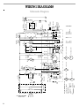
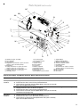
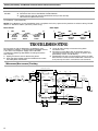
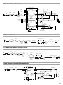
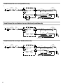
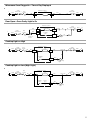
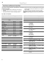
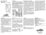
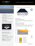
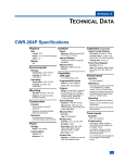
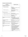
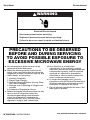
Tech Sheet
Do not discard
WARNING
Electrical Shock Hazard
Disconnect power before servicing.
Replace all parts and panels before operating.
Failure to do so can result in death or electrical shock.
PRECAUTIONS TO BE OBSERVED
BEFORE AND DURING SERVICING
TO AVOID POSSIBLE EXPOSURE TO
EXCESSIVE MICROWAVE ENERGY
a. Do not operate or allow the oven to be
operated with the door open.
b. Make the following safety checks on all
ovens to be serviced before activating the
magnetron or other microwave source, and
make repairs as necessary:
1. Interlock Operation
2. Proper Door Closing
3. Seal and Sealing Surfaces (Arcing, Wear
and Other Damage)
4. Damage to or Loosening of Hinges and
Latches
5. Evidence of Dropping or Abuse
c. Before turning on microwave power for any
service test or inspection within the
microwave generating compartments,
check the magnetron, waveguide or
transmission line, and cavity for proper
alignment, integrity and connections.
W10268748A / 461965199813
d. Any defective or misadjusted
components in the interlock, monitor,
door seal, and microwave generation and
transmission systems shall be repaired,
replaced, or adjusted by procedures
described in service manual before the
oven is released to the owner.
e. A microwave leakage check to verify
compliance with the Federal Performance
Standard should be performed on each
oven prior to release to the owner.
f. Do not attempt to operate the oven if the
door glass is broken.
FOR SERVICE TECHNICIAN’S USE ONLY
2
AC 120V/125V 60Hz
Power Cord
Cy
N
3
W
G
BK
L
P2-6
Y/G
Turntable Motor
FC Motor
CL
Cavity Light
Triac
7104
TT
Y
HF
HL
Hood Exhaust Fan
Hood (Cooktop) Light
L.V.
Transformer
Black
Blue
Red
Yellow
Green
FC
Relay
4904
W P2-5
Connector
Name
R
Valve
Relay
4921
Y P3-5
FCM
P2-4
HL Relay
4911
33K
P5-2
Magnetron
Thermostat
BU
W
TT
P5-1
BK
BU
R
Y
G
MW
Relay
4903
1
2
White
Brown
Orange
Yellow/Green
Gray
Turbo
Relay
4910
R
Symbol Notes:
Wire Color
Pin No.--1
P6-1
BR
GY
P3-1
P3-2
GY
BK P3-3
W P3-4
Fuse
BU P2-1
HL Relay
4912
GY P2-3
TT Relay
4906
CL Relay
4901
OR P2-7
HF Relay
4922
W
HF
Relay
4902
Primary
Interlock
Switch
FCM
FCTH
Diode 6101
Power
Resistor
BK
Golden
Tab
CL
Monitor
Interlock
Switch
FC Heater
PCBA
BK P6-1
W
P6-2
Fuse
20 Amp
P5-5
Golden
Tab
HF
White
Tab
FC
Thermostat
Secondary
Interlock
Switch
BK
R P2-2
Condition: Door Open.
Y/G
Cavity
Thermostat 2
BK
W
HL
R P6-5 R
BK
HL
White
Tab
Motor
Capacitor
Y
BU
P6-3
BK
AC Line Filter
Cx
Cy
P5-4
Cavity
BU Thermostat 1
BR
Dwg No.: MU-099-T - Rev. D
1
L
R
L
4
Y
BU
BK Fuse
20 Amp
P1
P21
P4
W
BR
OR
Y/G
GY
Humidity
Sensor
FC Sensor
Hood
Thermistor
Magnetron
FA
F
H.V.
Diode
H.V.
Capacitor
R
H.V.
Transformer
W
Red Tube
Black Tube
H
2
WIRING DIAGRAMS
Schematic Diagram
Black Tube
Parts Layout (not to scale)
AC
A
AB
AA
B
Z
C
D
E
F
Y
T
G
H
X
I
J
K
W
V
L
3551
T
P5
U
M
S
N
R
O
Q
A. Hood fan motor assembly
B. H.V. capacitor
C. AC line filter
D. Magnetron thermostat—opens at 257ºF
(125ºC), closes at 185ºF (85ºC)
E. Magnetron
F. Cavity thermostat 1—opens at 275ºF
(135ºC), closes at -31ºF (-35ºC)
G. Cavity thermostat 2—opens at 275ºF
(135ºC), closes at -31ºF (-35ºC)
H. Humidity sensor
N
M
P
I. H.V. transformer
J. FC thermoactuator
K. H.V. diode
L. Power resistor
M. Fuse holders
N. Line fuses
O. Motor capacitor
P. Hood thermistor
Q. Electronic control
R. Touch panel
S. Secondary interlock switch
T. Light holders
U. Hood (cooktop) light
V. Monitor interlock switch
W. Primary interlock switch
X. Turntable motor
Y. Cavity light
Z. FC thermostat—opens at 329ºF
(165ºC), closes at 257ºF (125ºC)
AA. FC thermistor
AB. FC ring heater
AC. FC motor
Primary, Secondary, and Monitor Interlock Switch Checkout Procedures
Switch
Check By
Primary
Interlock
1. Unplug microwave oven or disconnect power.
2. Disconnect the wires at the Primary Interlock Switch.
3. Check from the common terminal (black/brown wires) to the normally
open terminal (black/white wires).
-
+
1. Unplug microwave oven or disconnect power.
2. Disconnect the wires at the Primary Interlock Switch.
3. Check from the common terminal (black/brown wires) to the normally
closed terminal (orange wire).
+
-
1. Unplug microwave oven or disconnect power.
2. Disconnect the wires at the Secondary Interlock Switch.
3. Check from the common terminal (blue/white wires) to the normally
open terminal (blue/red wires).
-
+
Secondary
Interlock
Door Open
Door Closed
3
Primary, Secondary, and Monitor Interlock Switch Checkout Procedures
Switch
Check By
Door Open
Monitor
Interlock
1. Unplug microwave oven or disconnect power.
2. Disconnect the wires at the Monitor Interlock Switch.
3. Check from the common terminal (white/white wires) to the normally
closed terminal (blue/white wires).
Door Closed
+
-
(+) Continuity (-) No Continuity
NOTE: These diagrams are not intended to show a complete circuit; they represent the position of switches during “DOOR
OPEN” or “DOOR CLOSED” (continuity checks only).
Door Closed
L
(NC)
Door Open
(NO)
Primary
Interlock
Switch
N
(NO)
(NC)
Monitor
Interlock
Switch
L
(NO)
Secondary
Interlock
Switch
(NC)
N
(NO)
(NO)
(NC)
Primary
Interlock
Switch
Monitor
Interlock
Switch
(NO)
Secondary
Interlock
Switch
TROUBLESHOOTING
Do not continue with the diagnostics of appliance if the
household fuse is blown, a circuit breaker is tripped or if there
is less than 120-volt power supply at the wall outlet.
Complete the following steps before checking microwave
oven circuitry:
1. Unplug microwave oven or disconnect power.
2. Discharge high-voltage capacitor and disconnect white
wire from power transformer.
3. Check for loose wiring or incorrect wiring within
microwave oven.
4. All testing must be done with an ohmmeter having a
sensitivity of 20,000 ohms per volt DC or greater, and
powered by at least a 9-volt battery.
5. All operational checks using microwave energy must be
done with the microwave oven loaded with a minimum of
8 oz (250 mL) of water in a microwave-safe container.
Microwave (Non-sensor) Cooking
BR
OR
L
BK
Filter
Fuse
Cavity
Thermostat 2 20 Amp
BK
BK
BK
BK
Electronic Control
L.V.
Transformer
P2-4
P2-7
2
BU
P2-1
BU
Magnetron
Thermostat
Cavity
Secondary
H.V.
Interlock
Thermostat 1
Transformer
BR
W
W
BU
BU Switch
R
Fuse
20 Amp
Turntable
Motor
BU
BU
R
BK
TT
P2-2
P5-1
P5-2
W
BU
Cavity
Light
Turbo Relay
4910
MW Relay
4903
Primary
Interlock
Switch
P5-4
Filter
TT Relay
4906
CL Relay
4901
P2-3
HF Triac
7104
HF Relay
4902
GY
P3-2
P3-1
HF Relay
4922
GY
Power Resistor
4
P3-3
P3-4
GY
CL
P6-1
BK
BK
W
W
BU
BU
Y
R
Motor Capacitor P6-5
Y
R
HF
N
W
Microwave Sensor Cooking
BR
L
BK
Filter
Cavity
Thermostat 2
BK
BK
P2-7
BK
2
Fuse
20 Amp
BK
Turbo Relay
4910
MW Relay
4903
Primary
Interlock
Switch
TT Relay
4906
BR
R
Fuse
20 Amp
P2-2 R
H
1
Humidity
Sensor
P5-4
BU
P2-1
P2-4
OR
BK
P5-1
Cavity
Light
CL Relay
4901
GY
P2-3
Turntable
Motor
BU
TT
P5-2
W
N
P6-1
BK
BK
W
BU
Y
P3-4
P3-2
P3-1
GY
BU
W
P3-3
HF Relay
4902
BU
CL
HF Triac
7104
HF Relay
4922
BU
Magnetron
Thermostat Secondary
H.V.
Cavity
Interlock
Transformer
Thermostat 1
BU
BU Switch W
W
Filter
Electronic Control
L.V.
Transformer
W
BU
Y
R
HF
R
P6-5
Motor Capacitor
GY
Power Resistor
FC Heater Circuit
L
Filter
BK
Cavity
Thermostat 2
BK
BK
Electronic Control
Fuse
20 Amp
BK
W
Primary
Interlock
Switch
W
Monitor
Interlock
Switch
FC
Thermostat
W
FC Heater
W
FC Relay
4904
W
R
Cavity
Thermostat 1
BU
N
Filter
W
Secondary
Interlock
Switch
FC Motor and Thermal Actuator Circuit
L
Filter
BK
Cavity
Thermostat 2
BK
BK
Fuse
20 Amp
BK
FC Motor
W
BK
W
Primary
Interlock
Switch
Monitor
Interlock
Switch
Electronic Control
M
BK
Valve Relay
4921
BK
Y P3-5
BU
P2-1
BU
W
Cavity
Thermostat 1
BU
Filter
N
W
Secondary
Interlock
Switch
Thermal
Actuator
Hood Exhaust Fan on High Automatically
Filter
BK
Cavity
Fuse
Thermostat 2 20 Amp
BK
BK
Electronic Control
BK
BR
L.V.
Transformer
P2-4
Cavity
Thermostat 1
P2-1
HF Triac
7104
P3-3
HF Relay
4922
HF Relay
4902
BU
P5-4
W
W
BU
BK
BK
P6-1
BU
BU
Y
Y
R
R
P4
BU
Motor Capacitor
HF
BU
Filter
L
N
W
P6-5
Hood Thermistor
5
Hood Exhaust Fan on Low Speed Manually
L
BK
Filter
Cavity
Thermostat 2
BK
BK
Electronic Control
Fuse
20 Amp
BK
BR
L.V.
Transformer
P2-4
P2-1
BU
P5-4
Cavity
Thermostat 1
BU
BU
W
W
BU
HF Triac
7104
W
P3-4
GY
P6-2
GY
W
BU
BU
Y
R
HF
Filter
HF Relay
4902
P3-2
P3-1
HF Relay
4922
N
W
Y
R
P6-5
Motor Capacitor
Power Resistor
Hood Exhaust Fan on Medium Low and Medium Speed Manually
BK
Filter
Cavity
Thermostat 2
BK
BK
Electronic Control
Fuse
20 Amp
BK
BR
P2-4
L.V.
Transformer
P2-1
BU
P5-4
HF Triac
7104
W
P3-4
HF Relay
4922
HF Relay
4902
Cavity
Thermostat 1
BU
BU
W
W
BU
P6-2
W
BU
BU
Y
R
HF
Filter
L
N
W
Y
R
P6-5
Motor Capacitor
Hood Exhaust Fan on High / Medium Manually
Filter
BK
Cavity
Thermostat 2
BK
BK
Electronic Control
Fuse
20 Amp
BK
BR
L.V.
Transformer
P2-1
P2-4
BU
P5-4
HF Triac
7104
P3-3
HF Relay
4922
HF Relay
4902
BK
W
W
BU
BK
BU
BU
Y
R
Y
R
Motor Capacitor
6
P6-1
P6-5
Cavity
Thermostat 1
BU
BU
HF
Filter
L
N
W
Microwave Oven Plugged In—Time of Day Displayed
L
Filter
BK
Cavity
Fuse
Thermostat 2 20 Amp
BK
BK
BK
Electronic Control
L.V.
Transformer
BR
P2-4
P2-1
BU
P5-4
Cavity
Thermostat 1
BU
W
BU
Filter
N
W
Door Open—Oven Cavity Light Is On
Electronic Control
BR
L
BK
Filter
Cavity
Thermostat 2
BK
BK
Fuse
20 Amp
OR
BK
L.V.
Transformer
P2-4
P2-1
P2-7
CL Relay
4901
P2-3
Primary
Interlock
Switch
BU P5-4
GY
BU
W
CL
Cavity
Thermostat 1
BU
W
Filter
N
W
BU
Cavity Light
Cooktop Light on High
Electronic Control
L
BK
Filter
Cavity
Fuse
Thermostat 2 20 Amp
BK
BK
BK
BR
L.V.
Transformer
P2-4
Cavity
Thermostat 1
P5-4 BU
BU
P2-1
W
N
Filter
BU
W
W
HL Relay
4911
P2-6
Y P5-5 R
HL
Hood (Cooktop)
Light
Cooktop Light on Low (Night Light)
L
BK
Filter
Fuse
Cavity
Thermostat 2 20 Amp
BK
BK
Electronic Control
BK
BR
L.V.
Transformer
P2-4
P5-4
BU
P2-1
BU
Cavity
Thermostat 1
BU
W
Filter
N
W
W
HL Relay
4912
Diode
6101
P2-6
Y
P5-5
R
HL
Hood (Cooktop)
Light
7
Touch Panel
Touch Panel and Electronic Control Test
The microwave hood combination is provided with a self-diagnostic routine that can be accessed through the touch keypad.
To initiate this routine:
1. Press and hold the STOP/CLEAR button while opening
the door.
2. While still holding the STOP/CLEAR button, unplug the
microwave oven for 2 seconds, then plug it back in.
All VFD segments will be lit to indicate the test mode has
been entered.
3. Release the STOP/CLEAR button and close the door.
NOTE: When the door is closed, if the STOP/CLEAR button is
pressed during this diagnostic routine, you will exit the test
mode.
Key Tables for Test Mode
Key Name
Function
Display
Buzzer
Key Name
Start
-
-
1 beep
Baked Potato -
Setup Menu
NTC Sensor
Check
NTC Message
1 beep
Dinner Plate
Light
-
Key 03
1 beep
Vent Fan
-
Key 04
1 beep
Timer Set/Off
-
Key 05
1 beep
Warm Hold
-
Key 06
1 beep
Clock
-
Key 07
1 beep
Turntable On/Off -
Key 09
Function
Display
Buzzer
Key 31
1 beep
-
Key 32
1 beep
Quick Defrost -
Key 36
1 beep
0
Microwave Oven On
(1100 W) for
10 Seconds—
Relay 4903 &
Relay 4910-NO
MW TB
1 beep
1
Cavity Light On—
Relay 4901
CL
1 beep
2
Cavity Light & Turntable TT
On—Relay 4901 &
Relay 4906
1 beep
3
Microwave Oven On
(1000W) for
10 Seconds—
Relay 4903 &
Relay 4910-NC
MW
1 beep
4
FC Heater On for
10 Seconds—
Relay 4904
FC
1 beep
Add 30 Sec
-
Key 20
1 beep
Cook Time
-
Key 21
1 beep
Cook Power
-
Key 22
1 beep
Cook
Test Humidity Humidity Sensor 1 beep
Sensor
Message
Reheat
-
Key 24
1 beep
Defrost
-
Key 25
1 beep
5
FC Fan On—Relay 4921 FC-FAN
Kids Menu
-
Key 26
1 beep
6
Cooktop Light On
(High)—Relay 4911
HL_HIGH 1 beep
7
Cooktop Light On
(Low)—Relay 4912
HL_LOW 1 beep
8
Hood Fan On (High
HF_HIGH 1 beep
Speed)— Relay 4902,
Relay 4922 & Triac 7104
9
Hood Fan On (Low
Speed)— Relay 4902 &
Triac 7104
HF_LOW 1 beep
Stop/Clear
Exit Test Mode to
Standby
-
Soften/Melt
-
Key 29
1 beep
Convect Bake
Test FC
Sensor
FC Sensor
Message
1 beep
Convect Roast
-
Key 2B
1 beep
Steam/Simmer
-
Key 2D
1 beep
Popcorn
-
Key 30
1 beep
8
1 beep
1 beep
Microwave Oven Power Output Test
1. Place 8 oz (250 mL) of lukewarm water in the center of the
microwave oven.
2. Operate on HIGH power level for 2 minutes. Water should
be hot.
NOTE: If the water takes longer than 2 minutes to heat,
this may indicate either the operating voltage is lower
than 110 volts or there is a problem with the microwave
oven.
Failure Codes Indications
NOTE: Many of the problems listed in the chart below may be solved by power cycling: Unplug microwave oven or
disconnect power. After 1 minute, plug in microwave oven or reconnect power.
Display
Likely Failure Condition
Recommended Repair Procedure
Flashing
colon “:”
Power failure
After a power failure, the colon “:” will be flashing. Press any key to end this
indication. The colon will then be steady when in standby.
F2
Touch panel failure
1.
2.
3.
4.
5.
6.
7.
8.
Unplug microwave oven or disconnect power.
Replace touch panel.
Replace all parts and panels before operating.
Plug in microwave oven or reconnect power.
If problem persists, unplug microwave oven or disconnect power.
Replace electronic control.
Replace all parts and panels before operating.
Plug in microwave oven or reconnect power.
F3C
Cavity temperature sensor
failure
1.
2.
3.
4.
5.
6.
7.
8.
9.
Unplug microwave oven or disconnect power.
Check cavity temperature sensor connection.
Replace the cavity temperature sensor.
Replace all parts and panels before operating.
Plug in microwave oven or reconnect power.
If problem persists, unplug microwave oven or disconnect power.
Replace electronic control.
Replace all parts and panels before operating.
Plug in microwave oven or reconnect power.
F3H
Humidity sensor failure
1.
2.
3.
4.
5.
F6
MW relay
1. Unplug microwave oven or disconnect power.
2. Check the cable to Relay 4903.
3. Check to see if the relay (4903 on relay electronic control) contact has welded
closed.
4. Replace all parts and panels before operating.
5. Plug in microwave oven or reconnect power.
6. If problem persists, unplug microwave oven or disconnect power.
7. Replace electronic control.
8. Replace all parts and panels before operating.
9. Plug in microwave oven or reconnect power.
Unplug microwave oven or disconnect power.
Connect a new humidity sensor to the electronic control (at P1).
Replace all parts and panels before operating.
Plug in microwave oven or reconnect power.
If no failure code appears when starting sensor function, unplug microwave
oven or disconnect power.
6. Replace humidity sensor.
7. Replace all parts and panels before operating.
8. Plug in microwave oven or reconnect power.
9. If failure code appears when starting sensor function, unplug microwave oven
or disconnect power.
10. Replace electronic control.
11. Replace all parts and panels before operating.
12. Plug in microwave oven or reconnect power.
9
Component Tests
IMPORTANT:
■ Unplug microwave oven or disconnect power.
■ Remove the lead wires from the related component
before conducting any of the following tests.
■ Discharge the high-voltage capacitor and remove the
lead wires from the primary winding of the high-voltage
transformer before conducting any of the following
tests.
■ All operational checks using microwave energy must be
done with the microwave oven loaded with a minimum
of 8 oz (250 mL) of water in a microwave-safe
container.
■ Conduct a microwave energy test after performing any
tests or repairs to the microwave oven.
■ Check that all wire leads are in the correct positions
before operating the microwave oven.
■ Grasp wire connectors when removing the wire leads
from microwave oven parts.
■ All testing must be done with an ohmmeter having a
sensitivity of 20,000 ohms per volt DC or greater, and
powered by at least a 9-volt battery.
Components
Test/Results
H.V. Transformer
1. Unplug microwave oven or disconnect power.
2. Remove wire leads.
3. Measure resistance:
■ Primary winding: Less than 0.5 ohm (approximate)
■ Secondary winding: 90 ohms (approximate)
■ Filament winding: 0 ohms
4. Measure resistance:
■ Primary winding to grounding: Normal: Infinite
■ Filament winding to grounding: Normal: Infinite
Filament
(orange/red wires)
Primary
Secondary (white wire ground to transformer case)
Magnetron
1. Unplug microwave oven or disconnect power.
2. Remove wire leads. Check that the seal is in good condition.
3. Measure resistance:
■ Filament terminal: Normal: Less than 1 ohm
4. Measure resistance:
■ Filament to chassis: Normal: Infinite
H.V. Capacitor
1. Unplug microwave oven or disconnect power.
2. Remove wire leads.
3. Measure resistance:
■ Terminal to terminal: Normal: Momentarily indicates several ohms, and then
gradually returns to infinite.
■ Terminal to case: Normal: Infinite
H.V. Diode
NOTE: Some inexpensive meters may indicate infinite resistance in both directions.
1. Unplug microwave oven or disconnect power.
2. Measure resistance:
■ Forward: Normal: Continuity; Abnormal: Infinite
■ Reverse: Normal: Infinite; Abnormal: Continuity
Turntable Motor
1. Unplug microwave oven or disconnect power.
2. Remove wire leads.
3. Measure resistance:
■ Normal: 2.7k-3.8k ohms (approximate)
■ Abnormal: Infinite
Motor Capacitor
1. Unplug microwave oven or disconnect power.
2. Remove wire leads.
3. Measure resistance:
■ Normal: Momentarily 0 ohms, then goes to infinite
■ Abnormal: Infinite
10
Components
Test/Results
Humidity Sensor
1. Unplug microwave oven or disconnect power.
2. Remove the 3-pin connector from the electronic control (P1).
NOTE: Do not remove the attached resistor, which is used for internal resistance
calibration.
3. Measure resistance across pins 1 & 3, and across pins 2 & 3:
■ Normal: 2.8k ohms (approximate) at 77ºF (28ºC) +/- 18ºF (-10ºC)
■ Abnormal: Infinite
W
R
BK
Resistor
1. Unplug microwave oven or disconnect power.
2. Remove wire leads.
3. Measure resistance:
■ High Speed—Normal: Red (R) and Blue (BU) wires: 80 ohms (approximate);
Blue (BU) and Black (BK) wires: 35 ohms (approximate); Abnormal: Infinite
■ Low Speed—Normal: Red (R) and Blue (BU) wires: 80 ohms (approximate);
Blue (BU) and White (W) wires: 60 ohms (approximate); Abnormal: Infinite
Hood Thermistor
1. If “NTC SHORT, CALL FOR SERVICE” or “NTC OPEN, CALL FOR SERVICE”
scrolls on display, unplug microwave oven or disconnect power.
2. Measure resistance:
■ Normal: 10k ohms +/- 5% at 77ºF (25ºC)
■ Abnormal: Infinite/continuity
P5
355
1
Hood Exhaust Fan Motor
FC Ring Heater
1. Unplug microwave oven or disconnect power.
2. Remove wire leads.
3. Measure resistance:
■ Normal: 9 +/- 3 ohms
■ Abnormal: Infinite
FC Thermistor
1. Unplug microwave oven or disconnect power.
2. Remove wire leads.
3. Measure resistance:
■ Normal: 230k +/- 20% ohm at 77ºF (25ºC)
■ Abnormal: Infinite
FC Thermoactuator
1. Unplug microwave oven or disconnect power.
2. Remove wire leads.
3. Measure resistance:
■ Normal: 1.2k +/- 0.5k ohms
■ Abnormal: Infinite
FC Motor
1. Unplug microwave oven or disconnect power.
2. Remove wire leads.
3. Measure resistance:
■ Normal: 20 +/- 2 ohms
■ Abnormal: Infinite
AC Line Filter
2
1
3
1
L
3
U
2
N
4
4
Thermostats
FC Thermostats
Cavity Thermostats
Magnetron Thermostat
1. Unplug microwave oven or disconnect power.
2. Remove wire leads.
3. Measure resistance:
■ Normal: 1-3 (coil): Less than 1 ohm; 2-4 (coil): Less than 1 ohm;
3-4 (resistor): 550k-800k ohms
■ Abnormal: Infinite
NOTE: Refer to “Parts Layout” for opening and closing temperatures.
1. Unplug microwave oven or disconnect power.
2. Remove wire leads.
3. Measure continuity:
■ Normal: Continuity
■ Abnormal: Infinite
11
W10268748A / 461965199813
© 2009. All rights reserved.
6/09
FOR SERVICE TECHNICIAN’S USE ONLY