1
P/N 8514-186-001B
MODELS T900/T950
60LB CAPACITY
COMPUTER CONTROL
OPL WASHER
DEXTER
LAUNDRY,
INC.
OWNER'S BOOKLET
INSTALLATION & OPERATION
INSTRUCTIONS
________________________________________________________________________
TABLE OF CONTENTS
Safety Warnings
Maintenance Hints
Installation Instructions
Foundation Requirements
Mounting
Plumbing
Drain
Electrical
Fusing Requirements
Electrical Connections
Chemical Injection
Chemical Injection Hoses
Final Checkout
Operating Controls
Operating Instructions
End Of Cycle
Safety Door Lock
Motor Drive Indications
Computer Control Cycle Description
Programming Instructions - Editing Existing Cycle
Programming Instructions - Entering New Cycle
Washer Diagnostic Cycles
Cycle 31 Sequence
Rapid Advance Mode
Preset Cycle Information
Page #
2
2
3
3
3
3
3
6
6
6
7
7
7
10
11
12
12
12
12
14
15
17
17
19
21
LIST OF FIGURES
Figure
Figure
Figure
Figure
Figure
Figure
Figure
Figure
Figure
Figure
Figure
1-1 - Pedestal Mounting
1-2 - Floor Outline
1-3 - Machine Mounting Detail
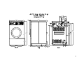
2 Washer Dimensions
3 Electrical Power Connections
4 Injection Signal and Connections
5 Specifications T900/T950
6 Water Usage
7 Push-button Control Switches
8 Recommended Detergent Quantity
9 Bath Setting Limits
4
4
4
5
6
7
8
9
10
11
13
Please read this information and retain for reference.
WARNING -
THIS WASHER IS EQUIPPED WITH DEVICES AND FEATURES RELATING TO ITS
SAFE OPERATION. TO AVOID INJURY OR ELECTRICAL SHOCK, DO NOT PERFORM
ANY SERVICING UNLESS QUALIFIED TO DO SO.
IT IS THE RESPONSIBILITY OF THE OWNER TO CHECK THIS EQUIPMENT ON A
FREQUENT BASIS TO ASSURE ITS SAFE OPERATION.
A machine should not be allowed to operate if any of the following occur:
•
•
•
•
Excessively high water level.
If machine is not connected to a properly grounded circuit.
If the door does not remain securely locked during the entire cycle.
Vibration or shaking from an inadequate mounting or foundation.
WARNING - FOR SAFETY
1.
2.
3.
4.
5.
6.
Always shut off power and water supply and wait a minimum of one minute
before servicing.
Do not overload the washer.
Do not bypass any safety devices of this washer.
Do not use volatile or flammable substances in or near this washer.
Do not attempt to open door when cylinder is in motion or it contains water.
Keep all panels in place. They protect against shock and injury and add
rigidity to the washer.
MAINTENANCE HINTS
DAILY
•
•
•
•
•
Clean
Clean
Check
Check
Leave
the
the
the
the
the
top and the cabinet to remove residue.
soap dispenser and lid.
drain valve for leaking and that it opens properly.
loading door for leaks. Clean the door seal of all foreign matter.
loading door open to aerate the washer when not in use.
QUARTERLY
Always shut off power and water supply and wait a minimum of one minute
before servicing.
• Check the V-belts for wear and proper tension.
• Clean lint and other foreign matter from around motor.
• Check all water connections for leaks.
• Wipe and clean the inside of the washer and check that all electrical
components are free of moisture and dust.
• Remove and clean water inlet hose filters. Replace if necessary.
• Check anchor bolts - retighten if necessary
Replace any and all panels that were removed to perform daily
and/or quarterly maintenance.
IMPORTANT:
2
INSTALLATION INSTRUCTIONS
All washers must be installed in accordance with all local, state and
national building, electrical, plumbing and other codes in effect.
WARNING - THESE INSTALLATION AND SERVICING INSTRUCTIONS ARE FOR
USE BY QUALIFIED PERSONNEL ONLY. TO AVOID INJURY AND ELECTRIC
SHOCK DO NOT PERFORM ANY SERVICING UNLESS QUALIFIED.
FOUNDATION REQUIREMENTS
This machine is designed for use on or over bare concrete floor - not to be used
above combustible flooring. The washer must be securely bolted to a substantial
concrete floor, or mounted upon a suitable base which is, in turn, securely
bolted to a substantial concrete floor.
CARE MUST BE STRESSED WITH ALL
FOUNDATION WORK TO INSURE A STABLE UNIT INSTALLATION, ELIMINATING POSSIBILITIES
OF EXCESSIVE VIBRATION.
All installations must be made on sound concrete
floors, 8" or thicker. Anchor bolts must be of a quality grade and a minimum
of 3/4" diameter. Six (6) mounting bolts must be used.
MOUNTING
A concrete pedestal or steel mounting base which elevates the machine a MAXIMUM
of 10" above the floor level is recommended to provide easy access to the
loading door.
Actual base height should be determined by application
considering access to loading door, access to soap dispenser and height of
loading carts. Allow a minimum of 24" of clearance behind the rear of the
machine, to provide access for motor removal. Refer to Fig. 1-1 & 1-2 for
machine bolt-down dimensions. Refer to Fig. 2 for overall washer dimensions.
If an elevated concrete pedestal is desired, it should be embedded into the
existing floor. Anchor bolts should be 3/4" x 8", grade 8 or better, headed by
a 4 inch square fish plate and should protrude 2 ½ inches above the finished
surface of the pedestal. If anchors are to be installed in existing concrete
we recommend Hilti Adhesive Anchor System w/Hilti HEA 3/4-6 5/8 Adhesive
Capsules and Hilti HAS 3/4-9 5/8 Super Rods. (For information contact Hilti
Customer Service 1-800-879-8000). EXPANSION ANCHORS ARE NOT RECOMMENDED FOR USE
IN CONCRETE FLOORS OR PEDESTALS. (See Fig. 1-1 and 1-3.)
PLUMBING
Water supply hoses are furnished with each machine.
on the hoses are 3/4-11 ½ NHT.
The threaded connections
Separate hot and cold water lines must be provided, maintaining 30 PSI to 120
PSI water flow pressure.
DRAIN
The drain outlet tube at the rear of the machine is 3 inches in diameter. Any
drain hose used must be lower than the drain valve to assure proper draining.
3
FLOOR OUTLINE
Figure 1-1
Figure 1-2
Figure 1-3
MACHINE MOUNTING DETAIL
CONCRETE PEDESTAL MOUNTING
4
5
ELECTRICAL
╔════════════════════════════════════════════════════════════════════╗
║
WARNING
║
║
SHUT OFF POWER AND WATER BEFORE OPENING ANY SERVICE PANELS.
║
╚════════════════════════════════════════════════════════════════════╝
Dexter T900/T950 washing machines are intended to be permanently installed
appliances. The machine should be connected to an individual branch circuit not
shared by lighting or other equipment. The connection should be sheathed in
liquid-tight flexible conduit, or equivalent, with conductors of the proper size
and insulation. No power cord is provided. Such connections should be made by
a qualified electrician, in accordance with the wiring diagram.
(Suggest
minimum wire size of 12 ga.)
FUSING REQUIREMENTS
15 Amp Time Delay (Dual Element) Fuse(s) (or equivalent circuit breaker).
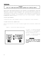
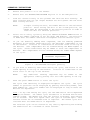
TO MAKE ELECTRICAL CONNECTIONS:
Remove screw and lift out cover located on upper left of machine (viewed from
back).
Figure 3 - Electrical Power Connections
If power is 208-240-3PH-60HZ
connect L1, L2, L3 and ground.
(If there is a high phase it
must be connected to L3.)
If power is 208-240-1PH-60HZ
connect L1, L2 and ground.
IMPORTANT
FOR SAFETY AND PROPER EQUIPMENT
OPERATION THE GROUND LUG MUST
BE CONNECTED TO A GOOD EXTERNAL
GROUND.
6
CHEMICAL INJECTION
Dexter T900/T950 washing machines are intended to be permanently installed
appliances.
The machine is intended to have a chemical injection system
operating with it. There are convenient electrical connection points for the
injection pumps shown in Figure 3. Up to four (4) independent pumps can be
controlled through the signals A, B, C and D. The injection pump signals are
115 VAC. The COM shown in Figure 3 is the common or return for these injection
signals. The complete injection system can be connected to FL1 and FL2 for
system power if other sources are not available. These connections require
fusing which are not provided by Dexter (Dashed lines shown in Figure 3). The
maximum current of the complete injection system is 7 Amps.
The four injection pump signals (A, B, C and D) are individually selected or in
combinations by the programming within the selected cycle. The recommended
signal connections are shown in Figure 4.
The selection of the signal is
explained in the Programming Instructions section of this manual.
FIGURE 4 - INJECTION SOURCE SIGNALS AND CONNECTION RECOMMENDATION
CHEMICAL INJECTION HOSES
Chemical Injection hoses are to be inserted into the injection inlet at the
upper right rear of the washer. These hoses should be inserted into the round
PVC pipe a minimum of 14" and a maximum of 18" to eliminate chemical buildup in
the pipe and/or restrict water flow to the tub. Secure the hoses as required.
FINAL CHECKOUT
After all mounting, plumbing and electrical work is completed, the washer should
be checked for water leaks and proper functioning by first running each step in
the diagnostic cycle (cycle # 31) and by running a complete cycle.
7
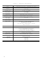
FIGURE 5 - T900/T950 SPECIFICATIONS
MODEL
WCND60HCX-12SX (T900) / WCND60HCX-12SZ (T950)
CAPACITY
9 CUBIC FT.
(UP TO 60#)
CYLINDER DIM.
30" DIA. x 22" DEPTH
GROSS WEIGHT
NET WEIGHT
1075 POUNDS
1025 POUNDS
ELECTRICAL
208-240 VAC, 60 HZ, 1 PH OR 3 PH
EXTRACTION FORCE
140 g’s (T900) / 200 g’s (T950)
WASH SPEED
SPIN SPEED
43 R.P.M.
573 R.P.M.(T900) / 685 R.P.M. (T950)
DRIVE SYSTEM
SOFT START REVERSING AC MOTOR DRIVE
WATER INLET
(T900/T950) 2 SOLENOID OPERATED VALVES
FLOW RATE, 9 GAL./MIN. EACH
FLOW PRESSURE, 30-120 PSI
(T950 ONLY) PLUS 2 SINGLE VALVES (12 GAL/MIN)
EACH, 30-120 PSI
DRAIN VALVE
3" OUTSIDE DIAMETER
PROGRAM CYCLES
30 USER PROGRAMMABLE CYCLES
(29 OF 30 PREPROGRAMMED AT THE FACTORY)
CYCLES TAILORED FOR SHIRT LAUNDRY,
HOTEL/HOTEL, HEALTH CARE AND FOOD & BEVERAGE
(SEE PRESET CYCLE INFORMATION TABLE)
TEST CYCLE
DIAGNOSTIC TEST PROGRAM
TEMPERATURES
USER SELECTABLE FROM 4 SETTINGS
MACHINE CONTROL:
KEYLOCK
ADVANCE/RUN/PROGRAM
MEMBRANE
8
STOP/EXIT
START/ENTER
SCROLL UP
SCROLL DOWN
FIGURE 6 - WATER USAGE
USAGE/BATH
EMPTY CYLINDER - NO LOAD
LOW LEVEL
FILL
HIGH LEVEL
FILL
19.0 gals.
25.7 gals.
31.4 gals.
38.3 gals.
Water required to fill bath preceded
by a drain without a spin.
18.6 gals.
23.6 gals.
Water required to fill bath preceded
by a drain with a spin.
24.7 gals.
32.1 gals.
FULL CYLINDER - LOADED
Water required to fill bath
starting with a dry load.
9
OPERATING CONTROLS
There are four (4) switches that control the washer operation.
shown below followed by an explanation of each switch.
Each switch is
Figure 7 - Push-button Control Switches
STOP (RED) Push-button - Depress momentarily.
Stops the washer during the cycle. All washer cycle information is retained,
the door remains locked and the water remains in the tub.
STOP (RED) Push-button - Depress and hold for 3 seconds or longer.
Stops the washer and clears the cycle. All washer cycle information is cleared,
the water is drained and the door is unlocked. The washer is ready for the next
wash cycle.
NOTE:
The door lock safety mechanism will prevent the door from opening for
up to 3 mins. when the washer is stopped during a cycle and the cycle
cleared.
WARNING
DEPRESSING AND HOLDING THE STOP IS AN EMERGENCY STOP BUTTON.
THIS DOES NOT DISCONNECT THE MACHINE FROM THE INPUT POWER.
START (GREEN) Push-button - Depress momentarily.
Starts the cycle shown on the display. If the cycle was stopped in the middle,
depressing the START will begin the cycle from the point at which the cycle was
stopped.
SCROLL UP ARROW (BLUE) Push-button - Depress momentarily / depress and hold.
Scroll Up increases the cycle number displayed by one each time the switch is
depressed. When the Scroll Up is held, the display cycle numbers will continue
to increase until cycle # 30 (cycle # 31 in Programming Mode) is reached at
which time the cycle number displayed will rollover back to cycle # 1.
SCROLL DOWN ARROW (BLUE) Push-button - Depress momentarily / depress and hold.
Scroll Down decreases the cycle number displayed by one each time the switch is
depressed. When the Scroll Up is held, the display cycle numbers will continue
to decrease until cycle # 1 is reached at which time the cycle number displayed
will rollover to cycle # 30 (cycle # 31 in Programming Mode).
10
OPERATING INSTRUCTIONS
1.
Ensure that power is on to the washer.
2.
Ensure that the ADVANCE/RUN/PROGRAM keylock is in the RUN position.
3.
Load the clothes loosely in the cylinder and latch the door securely. Be
sure clothing does not get caught between the door gasket and tub front
when closing the door.
NOTE:
To begin closing the door, the handle must be in the horizontal
position. After moving the door to the closed position, the
handle must be turned down to the vertical position in order to
latch the door for machine operation.
4.
Select one of thirty cycles by using the SCROLL UP/SCROLL DOWN buttons to
change the number indicated in the two digit LED display. The selection
is made when the number indicated corresponds with the desired cycle.
5.
If you are manually adding wash compounds, add low sudsing powdered
detergent in the amount shown below into the detergent compartment on top
of the machine. Location is illustrated on the black cover on the top of
the machine. This compartment will be flushed during the WASH segment of
the cycle. Rinse conditioners may be added to their own compartment if
desired. This compartment will be flushed during the FINAL RINSE segment
of the cycle.
POWERED
DETERGENT REQUIREMENT
T900/T950
½ CUP
Figure 8 - Recommended Detergent Quantity
6.
If you wish to manually add bleach during the cycle, add bleach in the
round opening in the top of the machine. Location is illustrated on the
black cover on the top of the machine.
NOTE:
7.
Any additional washing compounds may be added at the
appropriate time by pouring into the round opening in the top.
Push the green START button to start the cycle.
The cycle time remaining is displayed throughout the cycle. The cycle
number in operation can be displayed by pushing and holding START, then
push SCROLL UP. The cycle number will be displayed as long as these two
buttons are depressed.
Soak - At any time during the cycle, the red STOP button can be depressed
to stop the washer. All washer cycle information is retained and the door
remains locked. The washer will soak the load for 15 minutes, then agitate
for 30 seconds. This will repeat until the cycle is started again. This
feature allows for an extended soak if required. The washer cycle will
continue when the START button is depressed.
The selected cycle can be cleared at any time by depressing and holding
the STOP button for a minimum of three seconds.
11
END OF CYCLE
At the end of the cycle the machine stops, the END CYCLE LED lights, the alarm
sounds and the loading door unlocks allowing unloading of the machine.
SAFETY DOOR LOCK
This machine is equipped with a Safety Door Lock which prevents opening the
door if power is interrupted, until it is safe to do so.
If power failure occurs it will be necessary to wait 2 to 3 minutes before the
door can be opened.
T-900 MOTOR DRIVE INDICATORS
There is a five digit, seven segment, display on the drive which can be viewed
by removing the access cover at the top rear of the washer. There are also
small L.E.D.s on the left and below the display that can be viewed and used for
troubleshooting. The five seven segment digits will change value depending on
where the washer is during the wash cycle.
T-950 MOTOR DRIVE INDICATORS
There are three small red L.E.D.s located on the upper drive cover. They are
labeled as “READY”, “RUN” and “FAULT” and can be used for troubleshooting. The
definitions of the L.E.D.s are as follows:
Condition
Idle Mode – No
Cylinder Movement
Tumbling
Stop from Tumble
Ramp to
Intermediate or
Final Extract
Spin
Spinning
(Intermediate or
Extract)
Stop from Spin
(Intermediate or
Extract)
Faulted
READY
L.E.D.
ON
ON
ON
RUN L.E.D.
FAULT L.E.D.
OFF
ON
FLASHING
OFF
OFF
OFF
ON
ON
OFF
ON
ON
OFF
ON
FLASHING
OFF
ON
OFF
ON
COMPUTER CONTROL CYCLE DESCRIPTION
The T900/T950 computer control OPL machine has 30 different selectable cycles;
29 of the 30 cycles are preset with the most common industry applications. See
the Preset Cycle Information sheets for complete cycle information. If these
cycle settings do not meet the required application, each cycle is
reprogrammable by the user simply and reliably.
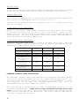
Each cycle has up to 9 baths which are Flush, Prewash, Wash, Rinse 1, 2, 3, 4,
5 and Final Rinse/Extract. There are five user selectable settings within each
bath to allow cycle tailoring to meet exact applications. The settings and the
limits of each are shown in the table below. The Scroll Up/Scroll Down buttons
are used to change the settings.
12
FIGURE 9 - BATH SETTING LIMITS
Settings for
Setting Limits
Description
each bath
Cycle Time
0 to 30 minutes
The Cycle time (tumble) settings are 0 min. to 30 min. in 1 min. increments for each bath. If
(1 min. increments) the setting is 0, then that bath is skipped over. For the Final Rinse /Extract bath, the
minimum time must be 1 min.
Water
HOT, WARM,
Temp.
COLD and NO
water bath. When the No Water bath is selected, the water level can be set to either high or low
WATER
and NO Injection will be made even if the injection source is programmed.
Water
The water temperature setting is displayed as HH = hot, CH = warm, CC = cold and EE = No
HIGH or LOW
The water level setting is displayed as HI for High level and LO for low level.
0 to 6
The injection source settings are 0 through 6 with 0 being no injection and settings 1 through
Level
Injection
Source
Spin Time
6 relating to an injection source. See Recommended Injection Table.
0 to 10 minutes
(1 min. increments)
The spin time settings are 0 min. to 10 min. in 1 min. increments. If the setting is 0, there
is no spin for the bath. Final Rinse/Extract minimum setting is 1 min.
13
PROGRAMMING INSTRUCTIONS
-
EDITING EXISTING CYCLE
There are 29 preset wash cycles programmed into the washer at the factory.
Although these cycles are common industry cycles, there may be a need to tailor
the cycle to meet an exact application. This can easily be done with the
following instructions. Note: It is recommended when changes are made to one
or more of the preset programs that the cycle number and the changes be
documented for later reference. Blank cycle sheets have been provided at the
end of the Preset Cycle Information section.
1.
Turn on the power to the washer.
2.
Turn Advance/Run/Program key to Program position (Program Mode LED lights).
3.
The Select Cycle LED is lit. Select the cycle to be edited by using the
SCROLL UP/SCROLL DOWN buttons. The selection is made when the number
displayed corresponds with the desired cycle.
4.
Push the green ENTER button.
Once depressed, the first of the nine cycle segment LED's will light (top
row). The cycle segments are: Flush, Prewash, Wash, Rinse 1, Rinse 2,
Rinse 3, Rinse 4, Rinse 5 and Final Rinse/Extract. The Select Cycle LED
is out.
5.
Use the Scroll Up / Scroll Down buttons to light the cycle segment to be
changed.
The sequence of steps below are repeated for each cycle segment until all
required segments are edited. The previously stored parameters will appear as
each part of the segment data is reviewed.
6.
Push the green ENTER button.
The Cycle Time LED lights (lower row of LED's) and the segment LED is out.
The tumble time for this segment will be shown on the display. If no
change is required, then continue to the next instruction. If this value
requires changing, then use the SCROLL UP/SCROLL DOWN buttons to change the
tumble time in 1 min. increments to the desired value, then continue to the
next instruction. Settings range is from 0 min. to 30 min. except for the
Final Rinse/Extract segment where the setting range is 1 min. to 30 min.
REMINDER: If the tumble time is set to zero, the segment will be skipped
in the wash cycle.
7.
Push the green ENTER button.
(The wash time has now been entered.)
The Water Temperature LED lights and the Cycle Time LED is out. The water
temperature for this segment is displayed. If no change is required, then
continue to the next instruction. If a change is required, then use the
SCROLL UP/SCROLL DOWN buttons to change the water temperature. {"HH" is
all hot water, "CC" is all cold water, “CH" is an even mix of hot and cold
water and “EE” is a no water bath} When the desired water temperature is
selected, continue to the next instruction.
8.
Push the green ENTER button.
(The water temperature has now been entered.)
The Water Level LED lights and the Water Temperature LED is out.
14
The water
level for this segment is displayed. If no change is required, then
continue to the next instruction. If a change is required, then use the
SCROLL UP/SCROLL DOWN buttons to change the water level. {"HI" is a high
water level and "LO" is a low water level} When the desired water level
is selected, continue to the next instruction.
When the No Water bath is selected, the water level has no effect.
water level can be selected.
9.
Push the green ENTER button.
Either
(The water level has now been entered.)
The Injection Source LED lights and the Water Level LED is out. The
injection source for this segment is displayed. If no change is required,
then continue to the next instruction. If a change is required, then use
the SCROLL UP/SCROLL DOWN buttons to change the injection source. See the
Injection Source table for proper selection. If zero is selected, then no
injection source is active for this segment. When the desired injection
source is selected, continue to the next instruction.
When the No Water bath is selected, injection signals are prohibited by the
electronic controller. The programmed injection source value is ignored.
10.
Push the green ENTER button.
(The injection source has now been entered.)
The Spin Time LED lights and the Injection Source LED is out. The spin
time for this segment is displayed.
If no change is required, then
continue to the next instruction. If this value requires changing, then
use the SCROLL UP/SCROLL DOWN buttons to change the spin time in 1 min.
increments to the desired value, then continue to the next instruction.
Settings range is from 0 min. to 10 min. except for the Final Rinse/Extract
segment where the setting range is 1 min. to 10 min. REMINDER: If the spin
time is set to zero, there will be no spin at the end of the bath.
11.
Push the green ENTER button.
(The extract time has now been entered.)
Once depressed, the Spin Time LED is out and the editing of one segment is
complete. The next sequential cycle segment LED lights, unless the segment
edited above was the Final Rinse/Extract segment.
If the Final
Rinse/Extract segment is edited, after step eleven, the cycle programming
is complete and the machine will return to the Programming Mode awaiting
a cycle select (Step 3).
To exit the programming mode, depress the red STOP button when one of
the nine cycle segment LED lights are lit. The programming changes made
prior to the program exit are retained and the cycle is updated.
PROGRAMMING INSTRUCTIONS
-
ENTERING NEW CYCLE
The T900/T950 comes from the factory with 29 preset wash cycles programmed into
the washer. Although these cycles are common industry cycles, there may be a
need to add a cycle to meet an exact application. This can easily be done with
the following instructions. Note: It is recommended when cycle(s) are made the
cycle number and the cycle steps be documented for later reference. Blank cycle
sheets have been provided at the end of the Preset Cycle Information section.
The instructions for entering a new cycle are the same as the editing a cycle
15
instructions. Again only the cycle segments required need to be programmed.
All other segments can be left unprogrammed by ensuring a zero time value is
entered in the Cycle time for each unused segment.
16
WASHER DIAGNOSTIC CYCLE
The diagnostic test cycle provided with every machine aids the user in verifying
correct operation of the washer after scheduled maintenance and aids the user
in identifying functional problems with the machine.
The diagnostic program, cycle 31, is an individual function test. This program
tests most of the functions of the machine (water valves, drive system, door
lock, etc...). The diagnostic program must be started from the program mode.
The keylock must be in the program position.
Below are two important notes about the diagnostic cycle:
•
Cycle Terminate - At any time during the diagnostic cycle, depressing and
holding the stop button for a minimum of 3 seconds terminates washer
activities and clears the cycle.
•
Injection Signals - The injection signals are not tested during the
diagnostic cycle.
Cycle 31 Sequence - Short individual function test
1.
Close the washer door.
2.
Turn the control key to the PROGRAM mode.
3.
Select cycle 31 using the SCROLL UP/SCROLL DOWN buttons.
4.
Push the green START button.
From this point, the operator must observe the functions of the washer to ensure
correct operation. With the top removed, the activation of each function can
be observed. Each step in this test will turn on an output on the I/O interface
assembly. Each time an output is active, the corresponding RED LED on the I/O
interface assembly will light. The outputs are clearly marked.
To end the test, push STOP and the machine will return to the programming mode
with cycle 31 displayed. The sequence of operation for the diagnostic cycle is
explained below:
•
All indicators are lit and "00" is on the display.
the washer is active.
•
Push the SCROLL UP button.
No other function of
The display will show 01.
For each number in the test, the function will be active when the START button
is pushed and will be inactive when the START button is released. Use the
SCROLL UP to move from one function to the next.
•
Step 1 - Lock the door.
•
Step 2 - Turn on thermoactuator #1 (lock).
•
Step 3 - Turn on thermoactuator #2 (unlock).
17
•
Step 4 - Close the drain valve.
•
Step 5 - Turn on the cold water to the tub.
The pressure switch low level setting can be tested at this point.
The drain valve is closed and cold water is on for as long as the
START button is pushed. When the water level reaches a low level,
the water valve will turn off and no additional cold water can be
added. (The time required to reach a low water is dependent on input
water pressure. It may require several minutes.)
•
Step 6 - Turn on the cold water to the dispenser.
The pressure switch low level setting can also be tested with this
step. For details see Step 5.
•
Step 7 - Turn on the hot water to the tub.
The pressure switch high level setting of the pressure switch can be
tested at this point. The drain valve is closed and hot water on for
as long as the START button is pushed. When the water level reaches
a high level, the water valve will turn off and no additional hot
water can be added. (The time required to reach a high water is
dependent on input water pressure. It may require several minutes.)
•
Step 8 - Turn on the hot water to the dispenser.
The pressure switch high level setting can also be tested with this
step. For details see Step 7.
•
Step 9 - Forward tumble.
•
Step 10 - Reverse tumble.
•
Step 11 - Open drain.
•
Step 12 - Intermediate spin.
The I/O interface outputs labeled Reverse and Speed1 will be active
(the two RED LED’s will light).
•
Step 13 - Full speed spin.
The I/O interface outputs labeled Reverse, Speed1 and Speed2 will be
active (the three RED LED’s will light).
DO NOT USE STEP 14 IF YOU HAVE CUSTOMIZED CYCLES PROGRAMMED AS
THIS WILL SET THE CYCLES BACK TO THE FACTORY PRESETS.
•
Step 14 - Preset Cycles. Push START and hold, then push SCROLL UP.
will reset the DEXTER preset cycles back to the factory settings.
This
At cycle complete, switch the Advance/Run/Program switch to the Run position
and the unit is ready to select a run cycle.
18
RAPID ADVANCE MODE
To enter the Rapid Advance mode, insert the key into the Rapid
Advance/Run/Program lock and turn the key counter-clockwise (CCW). The
Rapid Advance mode must be entered during the cycle. If the cycle has not
yet started, press the “DOWN” button or the “UP” button to choose a cycle
and then the “START” button to begin the cycle.
To advance to the next step in the cycle, push both the “UP” and “START”
buttons at the same time. The display will show “Ad” (advance).
If advancing during a bath, all water valves will turn off and the drain
will open until the “open drain” step is completed. The cycle will then
continue to the next bath or to the spin of the current bath if the
programming includes spin time.
If advancing during a chemical injection of a bath or after a chemical
injection of the bath but before the low water level is reached, the
injector will turn off and the hot and the cold water valves to the tub will
turn on until the low water level is reached or for 30 seconds, whichever
comes first. Then the drain will open and proceed to the next step after
the “open drain” step is completed.
If advancing before a chemical injection of the bath, the drain will open
immediately and the cycle will proceed to the next step when the “open
drain” step is completed.
If advancing during a spin, the tumbler will begin to decelerate
immediately. However the cycle may proceed to the next bath before the
tumbler comes to a complete stop. The cycle cannot be advanced further
while the tumbler is decelerating.
If a temperature PCB is installed in the I/O PCB and the temperature
programmed from 20 to 90 (Celsius), advancing will turn off the heater relay
or steam valve immediately, if either is on, and open the drain after a
three second delay. If the display shows a water temperature from 65 to 90
(may be displayed by pressing the “DOWN” and “START” buttons together), the
drain will close again when the washer indicates empty and the hot and the
cold water valves to the tub will turn on until the low water level is
reached. The cycle will then continue to the next bath, or if programmed, to
the spin of the current bath.
To exit the Rapid Advance mode during the cycle, turn the key to Run.
cycle will continue normally.
The
Notes:
• The cycle cannot be advanced during the “open drain” step of the bathes.
• The cycle cannot be advanced when the hot and cold water valves to the
tub are on after advancing during or after a chemical injection.
• The cycle cannot be advanced again while the hot and cold water valves to
the tub are on after advancing when the water temperature was 65 to 90.
• The Rapid Advance mode may only be entered after a cycle is started.
• The indicator lights will show to which segment the cycle has been
advanced.
19
•
•
The Rapid Advance mode cannot skip the final three tumbles of the cycle.
The door lock may remain activated for a couple minutes after the cycle
has been completed.
The chemical injection signals will not turn on if the Rapid Advance mode
is entered before the injection.
To end the cycle without waiting for the time to count down, push and hold
the “STOP” button for 5 seconds or more. The display will then show the
cycle number and be ready to start the cycle.
20
OPL 60 POUND WASHER
COMPUTER CONTROLLED
PRESET CYCLE INFORMATION
APPLICATION
Shirt/Laundry
CYCLE #
1
2
DESCRIPTION
Shirts (No Starch)
Shirts (Starch)
Hotel/Motel
3
4
5
6
7
8
9
10
11
12
White Sheets
White Pillowcases
White Towels, Bath Mats, Wash Cloths
Colored Sheets & Towels
Delicate Wash
Housekeeping Rags & Mops
Housekeeping Uniforms
Stain Treatment
Reclaim
Part 1
Part 2
Health Care
13
14
15
16
17
Sheets & Pillowcases
Towels
Diapers & Pads
Personals
Delicate
Food & Beverage
18
19
20
21
22
23
24
25
26
27
White (Cotton/Blend) Table Linen
Colored (Cotton/Blend) Table Linen
White 100 % Polyester Table Linen
Colored 100 % Polyester Table Linen
White Chef Coats
Kitchen and Maintenance Rags
White/Colored (Cotton/Blend) Table Linen
White/Colored 100 % Polyester Table Linen
White Chef Coats
Kitchen and Maintenance Rags
Other
28
29
30
Oxygen Bleach - Terry
Oxygen Bleach - Terry (No iron)
Open
Test
31
Test Diagnostic
21
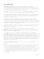
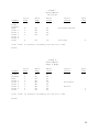
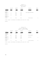
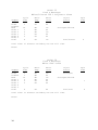
CYCLE 1
Shirt/Laundry
Shirts (No Starch)
Segment
Flush
Prewash
Wash
Rinse 1
Rinse 2
Rinse 3
Rinse 4
Rinse 5
Final
Cycle
Time
Water
Temp
Water
Level
12
2
2
2
HH
CH
CH
CH
LO
HI
HI
HI
4
CH
LO
Inject
Source
Spin
Time
Detergent/Bleach1
3
Total Time: 25 minutes excluding the tub fill time.
Notes: 1.
Use only oxygen bleach in shirt laundries.
DO NOT USE CHLORINE BLEACH.
CYCLE 2
Shirt/Laundry
Shirts (Starch)
Segment
Flush
Prewash
Wash
Rinse 1
Rinse 2
Rinse 3
Rinse 4
Rinse 5
Final
Cycle
Time
Water
Temp
Water
Level
Inject
Source
12
2
2
2
HH
CH
CH
CH
LO
HI
HI
HI
Detergent/Bleach1
7
CH
LO
Starch
Total Time: 28 minutes excluding the tub fill time.
Notes: 1.
22
Use only oxygen bleach in shirt laundries.
DO NOT USE CHLORINE BLEACH.
Spin
Time
3
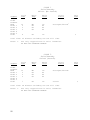
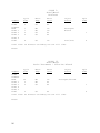
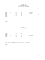
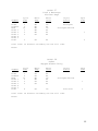
CYCLE 3
Hotel/Motel
White Sheets
Segment
Flush
Prewash
Wash
Rinse 1
Rinse 2
Rinse 3
Rinse 4
Rinse 5
Final
Cycle
Time
Water
Temp
Water
Level
Inject
Source
7
7
2
2
HH
HH
CH
CH
LO
LO
HI
HI
Detergent
Bleach
4
CH
LO
Sour/Soft
Spin
Time
1
4
Total Time: 27 minutes excluding the tub fill time.
Notes:
CYCLE 4
Hotel/Motel
White Pillowcases
Segment
Flush
Prewash
Wash
Rinse 1
Rinse 2
Rinse 3
Rinse 4
Rinse 5
Final
Cycle
Time
Water
Temp
Water
Level
Inject
Source
7
1
7
2
2
HH
HH
HH
CH
CH
LO
HI
LO
HI
HI
Detergent
4
CH
LO
Sour/Soft
Bleach
Spin
Time
1
4
Total Time: 28 minutes excluding the tub fill time.
Notes:
23
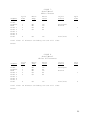
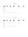
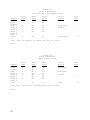
CYCLE 5
Hotel/Motel
White Towels
Segment
Flush
Prewash
Wash
Rinse 1
Rinse 2
Rinse 3
Rinse 4
Rinse 5
Final
Cycle
Time
Water
Temp
Water
Level
Inject
Source
7
1
7
2
2
HH
HH
HH
CH
CH
LO
HI
LO
HI
HI
Detergent
4
CH
LO
Sour/Soft
Bleach
Spin
Time
1
5
Total Time: 29 minutes excluding the tub fill time.
Notes:
CYCLE 6
Hotel/Motel
Color Sheets
Segment
Flush
Prewash
Wash
Rinse 1
Rinse 2
Rinse 3
Rinse 4
Rinse 5
Final
Cycle
Time
Water
Temp
Water
Level
Inject
Source
7
2
2
2
HH
HH
CH
CH
LO
HI
HI
HI
Detergent/Bleach
4
CH
LO
Sour/Soft
1
Total Time: 22 minutes excluding the tub fill time.
Notes:
24
Spin
Time
4
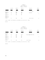
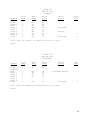
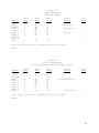
CYCLE 7
Hotel/Motel
Delicate
Segment
Flush
Prewash
Wash
Rinse 1
Rinse 2
Rinse 3
Rinse 4
Rinse 5
Final
Cycle
Time
Water
Temp
Water
Level
Inject
Source
8
2
2
2
CH
HH
CH
CH
HI
HI
HI
HI
Detergent/Bleach
4
CH
LO
Sour/Soft
Spin
Time
4
Total Time: 22 minutes excluding the tub fill time.
Notes:
CYCLE 8
Hotel/Motel
Rags & Mops
Segment
Flush
Prewash
Wash
Rinse 1
Rinse 2
Rinse 3
Rinse 4
Rinse 5
Final
Cycle
Time
3
2
2
2
7
2
7
2
2
Water
Temp
Water
Level
Inject
Source
CH
CH
CH
CH
HH
HH
HH
CH
CH
HI
HI
HI
HI
LO
HI
LO
HI
HI
Detergent
Bleach
Spin
Time
1
5
Total Time: 35 minutes excluding the tub fill time.
Notes:
25
CYCLE 9
Hotel/Motel
Uniforms
Segment
Flush
Prewash
Wash
Rinse 1
Rinse 2
Rinse 3
Rinse 4
Rinse 5
Final
Cycle
Time
Water
Temp
Water
Level
Inject
Source
2
CH
HI
7
7
2
2
HH
HH
CH
CH
LO
LO
HI
HI
Detergent
Bleach
4
CH
LO
Sour/Soft
Spin
Time
1
4
Total Time: 29 minutes excluding the tub fill time.
Notes:
CYCLE 10
Hotel/Motel
Stain Treatment - Chlorine Bleach
Segment
Flush
Prewash
Wash
Rinse 1
Rinse 2
Rinse 3
Rinse 4
Rinse 5
Final
Cycle
Time
Water
Temp
Water
Level
30
2
2
2
HH
HH
HH
CH
LO
HI
HI
HI
2
CH
HI
Inject
Source
Detergent/Bleach
Total Time: 43 minutes excluding the tub fill time.
Notes:
26
Spin
Time
1
4
CYCLE 11
Hotel/Motel
Reclaim (Part 1)
Segment
Flush
Prewash
Wash
Rinse 1
Rinse 2
Rinse 3
Rinse 4
Rinse 5
Final
Cycle
Time
Water
Temp
Water
Level
Inject
Source
20
3
HH
HH
LO
HI
Manual
3
HH
HI
Spin
Time
1
Total Time: 27 minutes excluding the tub fill time.
Notes:
CYCLE 12
Hotel/Motel
Reclaim (Part 2)
Segment
Flush
Prewash
Wash
Rinse 1
Rinse 2
Rinse 3
Rinse 4
Rinse 5
Final
Cycle
Time
Water
Temp
Water
Level
3
20
3
3
10
3
HH
HH
HH
HH
HH
HH
HI
LO
HI
HI
LO
HI
3
CH
HI
Inject
Source
Spin
Time
Manual
Bleach
1
4
Total Time: 50 minutes excluding the tub fill time.
Notes:
27
CYCLE 13
Health Care
Sheets & Pillowcases
Segment
Flush
Prewash
Wash
Rinse 1
Rinse 2
Rinse 3
Rinse 4
Rinse 5
Final
Cycle
Time
Water
Temp
Water
Level
Inject
Source
3
2
7
7
2
2
CH
CH
HH
HH
CH
CH
HI
HI
LO
LO
HI
HI
Detergent
Bleach
4
CH
LO
Sour/Soft
Spin
Time
1
4
Total Time: 32 minutes excluding the tub fill time.
Notes:
CYCLE 14
Health Care
Towels
Segment
Flush
Prewash
Wash
Rinse 1
Rinse 2
Rinse 3
Rinse 4
Rinse 5
Final
Cycle
Time
Water
Temp
Water
Level
3
2
7
1
7
2
2
CH
CH
HH
HH
HH
CH
CH
HI
HI
LO
HI
LO
HI
HI
4
CH
LO
Inject
Source
Detergent
Bleach
Sour/Soft
Total Time: 34 minutes excluding the tub fill time.
Notes:
28
Spin
Time
1
5
CYCLE 15
Health Care
Diapers
Segment
Flush
Prewash
Wash
Rinse 1
Rinse 2
Rinse 3
Rinse 4
Rinse 5
Final
Cycle
Time
3
2
2
7
2
7
2
2
4
Water
Temp
Water
Level
CH
CH
CH
HH
HH
HH
CH
CH
CH
HI
HI
HI
LO
HI
LO
HI
HI
LO
Inject
Source
Spin
Time
Detergent
Bleach
Sour/Soft
1
4
Total Time: 36 minutes excluding the tub fill time.
Notes:
CYCLE 16
Health Care
Personals
Segment
Flush
Prewash
Wash
Rinse 1
Rinse 2
Rinse 3
Rinse 4
Rinse 5
Final
Cycle
Time
Water
Temp
Water
Level
3
CH
HI
7
2
2
2
HH
HH
CH
CH
LO
HI
HI
HI
4
CH
LO
Inject
Source
Spin
Time
Detergent/Bleach
Sour/Soft
4
Total Time: 24 minutes excluding the tub fill time.
Notes:
29
CYCLE 17
Health Care
Delicate
Segment
Flush
Prewash
Wash
Rinse 1
Rinse 2
Rinse 3
Rinse 4
Rinse 5
Final
Cycle
Time
Water
Temp
Water
Level
2
CH
HI
7
2
2
2
CH
CH
CH
CH
HI
HI
HI
HI
4
CH
HI
Inject
Source
Spin
Time
Detergent/Bleach
Sour/Soft
3
Total Time: 22 minutes excluding the tub fill time.
Notes:
CYCLE 18
Food & Beverage
White Cotton Linen
Segment
Flush
Prewash
Wash
Rinse 1
Rinse 2
Rinse 3
Rinse 4
Rinse 5
Final
Cycle
Time
Water
Temp
Water
Level
Inject
Source
2
CH
HI
10
2
7
2
2
HH
HH
HH
CH
CH
LO
HI
LO
HI
HI
Bleach
4
CH
LO
Sour/Starch
Detergent
Total Time: 34 minutes excluding the tub fill time.
Notes:
30
Spin
Time
1
4
CYCLE 19
Food & Beverage
Colored Cotton Linen
Segment
Flush
Prewash
Wash
Rinse 1
Rinse 2
Rinse 3
Rinse 4
Rinse 5
Final
Cycle
Time
Water
Temp
Water
Level
Inject
Source
2
CH
HI
10
7
2
2
HH
HH
CH
CH
LO
LO
HI
HI
Detergent
Bleach
4
CH
LO
Sour/Starch
Spin
Time
1
4
Total Time: 32 minutes excluding the tub fill time.
Notes:
CYCLE 20
Food & Beverage
White 100 % Polyester Linen
Segment
Flush
Prewash
Wash
Rinse 1
Rinse 2
Rinse 3
Rinse 4
Rinse 5
Final
Cycle
Time
Water
Temp
Water
Level
Inject
Source
2
CH
HI
10
2
7
2
2
HH
HH
HH
CH
CH
LO
HI
LO
HI
HI
Bleach
4
CH
LO
Sour/Starch
Spin
Time
Detergent
4
Total Time: 33 minutes excluding the tub fill time.
Notes:
31
CYCLE 21
Food & Beverage
Colored 100 % Polyester Linen
Segment
Flush
Prewash
Wash
Rinse 1
Rinse 2
Rinse 3
Rinse 4
Rinse 5
Final
Cycle
Time
Water
Temp
Water
Level
Inject
Source
2
CH
HI
10
7
2
2
HH
HH
CH
CH
LO
LO
HI
HI
Detergent
Bleach
4
CH
LO
Sour/Starch
Spin
Time
1
4
Total Time: 32 minutes excluding the tub fill time.
Notes:
CYCLE 22
Food & Beverage
White Chef Coats
Segment
Flush
Prewash
Wash
Rinse 1
Rinse 2
Rinse 3
Rinse 4
Rinse 5
Final
Cycle
Time
Water
Temp
Water
Level
Inject
Source
5
1
8
2
7
2
2
HH
HH
HH
HH
HH
CH
CH
LO
HI
LO
HI
LO
HI
HI
Detergent
4
CH
LO
Detergent
Bleach
Sour
Total Time: 36 minutes excluding the tub fill time.
Notes:
32
Spin
Time
1
4
CYCLE 23
Food & Beverage
Kitchen Rags
Segment
Flush
Prewash
Wash
Rinse 1
Rinse 2
Rinse 3
Rinse 4
Rinse 5
Final
Cycle
Time
Water
Temp
Water
Level
Inject
Source
5
2
8
2
7
2
HH
HH
HH
HH
HH
CH
LO
HI
LO
HI
LO
HI
Detergent
2
CH
HI
Spin
Time
Detergent
1
Bleach
1
5
Total Time: 35 minutes excluding the tub fill time.
Notes:
CYCLE 24
Food & Beverage
White/Colored (Cotton/Blend) Linen
Segment
Flush
Prewash
Wash
Rinse 1
Rinse 2
Rinse 3
Rinse 4
Rinse 5
Final
Cycle
Time
Water
Temp
Water
Level
Inject
Source
2
CH
HI
10
1
2
2
2
HH
HH
HH
CH
CH
LO
HI
HI
HI
HI
Detergent/Bleach
4
CH
LO
Sour/Starch
Spin
Time
1
4
Total Time: 28 minutes excluding the tub fill time.
Notes:
33
CYCLE 25
Food & Beverage
White/Colored 100 % Polyester Linen
Segment
Flush
Prewash
Wash
Rinse 1
Rinse 2
Rinse 3
Rinse 4
Rinse 5
Final
Cycle
Time
Water
Temp
Water
Level
Inject
Source
2
CH
HI
10
1
2
2
2
HH
HH
HH
CH
CH
LO
HI
LO
HI
HI
Detergent/Bleach
4
CH
LO
Sour/Starch
Spin
Time
4
Total Time: 27 minutes excluding the tub fill time.
Notes:
CYCLE 26
Food & Beverage
White Chef Coats
Segment
Flush
Prewash
Wash
Rinse 1
Rinse 2
Rinse 3
Rinse 4
Rinse 5
Final
Cycle
Time
Water
Temp
Water
Level
Inject
Source
5
1
10
2
2
2
HH
HH
HH
HH
CH
CH
LO
HI
LO
HI
HI
HI
Detergent
4
CH
HI
Detergent/Bleach
1
Sour/Soft
Total Time: 31 minutes excluding the tub fill time.
Notes:
34
Spin
Time
4
CYCLE 27
Food & Beverage
Kitchen Rags
Segment
Flush
Prewash
Wash
Rinse 1
Rinse 2
Rinse 3
Rinse 4
Rinse 5
Final
Cycle
Time
Water
Temp
Water
Level
Inject
Source
5
2
10
1
2
2
HH
HH
HH
HH
HH
CH
LO
HI
LO
HI
HI
HI
Detergent
2
CH
HI
Spin
Time
Detergent/Bleach
1
5
Total Time: 30 minutes excluding the tub fill time.
Notes:
CYCLE 28
Other
Oxygen Bleach Terry
Segment
Flush
Prewash
Wash
Rinse 1
Rinse 2
Rinse 3
Rinse 4
Rinse 5
Final
Cycle
Time
Water
Temp
Water
Level
3
2
10
2
2
2
CH
CH
HH
HH
CH
CH
HI
HI
LO
HI
HI
HI
4
CH
LO
Inject
Source
Spin
Time
Detergent/Bleach
1
Sour/Soft
3
Total Time: 29 minutes excluding the tub fill time.
Notes:
35
CYCLE 29
Other
Oxygen Bleach Terry (No Iron)
Segment
Flush
Prewash
Wash
Rinse 1
Rinse 2
Rinse 3
Rinse 4
Rinse 5
Final
Cycle
Time
Water
Temp
Water
Level
3
2
10
2
2
2
CH
CH
HH
HH
CH
CH
HI
HI
LO
HI
HI
HI
4
CH
LO
Inject
Source
Spin
Time
Detergent/Bleach
1
Sour/Soft
5
Total Time: 31 minutes excluding the tub fill time.
Notes:
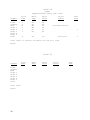
CYCLE 30
Segment
Cycle
Time
Flush
Prewash
Wash
Rinse 1
Rinse 2
Rinse 3
Rinse 4
Rinse 5
Final
Total Time:
Notes:
36
Water
Temp
Water
Level
Inject
Source
Spin
Time
CYCLE
Segment
Cycle
Time
Water
Temp
Water
Level
Inject
Source
Spin
Time
Inject
Source
Spin
Time
Flush
Prewash
Wash
Rinse 1
Rinse 2
Rinse 3
Rinse 4
Rinse 5
Final
Total Time:
Notes:
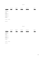
CYCLE
Segment
Cycle
Time
Water
Temp
Water
Level
Flush
Prewash
Wash
Rinse 1
Rinse 2
Rinse 3
Rinse 4
Rinse 5
Final
Total Time:
Notes:
37