1
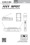
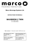
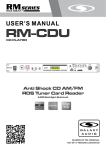
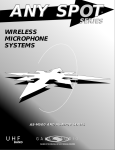
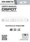
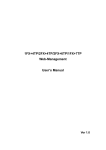
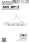
CTS
UHF
USER'S MANUAL
®
Contents
Introduction..................................................................................................1
System Components.....................................................................................2
Functions of the CTSR Receiver.................................................................3-4
Connecting a Receiver to the RF Distributor...................................................5
System Setup............................................................................................6-8
HH85 Handheld Transmitter..........................................................................9
MBP85 Body Pack..................................................................................10-11
Main Functions Description of Transmitters..................................................12
Handheld and Body Pack Transmitter.....................................................13-14
Troubleshooting..........................................................................................15
Specifications.............................................................................................16
Introduction
Thank you for choosing the Galaxy Audio CTS Wireless
Microphone System. You have joined hundreds of thousands of
other satisfied Galaxy customers. Since 1977 Galaxy Audio’s
professional experience in design and manufacturing ensure
our products quality, performance and reliability.
For the most up to date manual and information
visit www.galaxyaudio.com.
1
CTS System Components
System Overview
The CTS system is specifically designed for a variety of performance art. The
CTS system has 18 different groups, and each group consists of 14
compatible receiving channels. The CTS system is capable of searching
vacant channels automatically, and synchronizing with transmitter accurately.
The CTS system consists of a receiver, transmitter, and power adaptor. The
transmitter can either be a handheld or a belt pack (choice of headset or
lavaliere mic). Systems also include a ¼" signal cable, (2) AA batteries and a
user manual.
All CTS systems include the following components:
CTS Receiver
One ¼" Audio Cable
Power Adapter
Two Antennas
Single Rack Ears
User Manual
Handheld Microphone Systems include the following:
HH85 Handheld Transmitter
Lavalier/Headset Microphone systems include the
following:
MBP85 Bodypack Transmitter
Microphone (choice of Lavalier, or Headset)
2
Functions of the CTSR Receiver
CTSR Receiver Features
Front Panel
Power Switch.
With red light indicator, press it one second to turn it
on or off.
System Menu up button
IR Port
SQL decrease button
IR Sync Signal Button: Pressing button starts 10 second
transmitter synchronization indicated by flashing Icon.
During the 10 seconds aim the transmitter IR port at the
receiver IR port and the transmitter will sync to the
receiver frequency.
SQL increase button
System Menu down button
Automatically Search
for vacant channels
LCD Display Panel
System setting button
3
Functions of the CTSR Receiver
Rear Panel
1
DC power socket
2
Balanced audio output socket
3
Un-balanced audio output socket: 1/4 inch
4
Antenna Socket
Receiver LCD Functions
Function
Display
IR port
Audio Level
Current Group Number
Current Channel Number
Current Frequency
Mute, it will disappear when the mic is on
Receiving Signal Status
Squelch Level Setting
Antenna A B status
Automatically Search for vacant channels
4
Connecting Receiver to the RF Distributor
Connecting Receiver to the RF Distributor
Rack mount side panel
DC power adapter
Balanced output cable
1/4 inch Output cable
5
System Setup
1. IR SYCN Setting
Press the
button, the icon will flash for 10 seconds. During the 10
seconds aim the transmitter IR port at the receiver IR port and the
transmitter will sync to the receiver frequency. When the sync is complete
the icon will disappear and the display will return to its normal state.
6
System Setup
2. Selecting Frequency
Press
button,the GP flashes to indicate the group can be chosen by
pressing the
or
button,to confirm press the
button.It will
return back to the original state without any operation within 5 seconds.
Press
to confirm the group selection, the CH flashes to indicate the
channel can be chosen, press the
or
button to choose, Press
again to exit setting mode automatically after confirmation.
When choosing frequencies from the “U” group, press
top three numbers before the point flash, press
1MHz for every push, and press
number after the point blink, press
for 25Khz.
button, and the
buttons to choose,
again to confirm, then the last three
buttons to choose, every step
3. SQ Setting and Change
The CTSR receiver has a build-in adjustable SQL(Squelch Level) function
which silences the output when the receiver does not get a strong or quality
signal from the transmitter, instead of reproducing noise. When squelch is
adjusted, the threshold of the signal quality or level is adjusted.
Press SQL
or
to change the value. The higher value means the
lower reception sensitivity and stronger anti-interference ability. The selection
should be based on the use of different locations to achieve the best effect.
7
System Setup
4. Automatically Search for Vacant Channel
Press
,
icon will start to flash ,then available channels will be shown
on the LCD display. For example , the LCD display shows 15, that means there are 15
vacant channels available. Then Press the button
and
to select an
appropriate channel. Once a channel is selected, press
to confirm the setting.
If no vacant channel can be found within 5 seconds, receiver will automatically
return to the original state.
5. Auto Muting
The
icon is displayed in the receiver LCD screen when the
frequency is different between receiver and transmitter or the receiver
can't receive any signal from the transmitter.
6. Locking and Unlocking
Press
and hold for one second until LCD shows "
". At this time,
all buttons except Power/Mute will be disabled. All receiver’s setting
functions are now locked. To unlock, press
and hold it until the “ “
icon disappears,the receiver is now unlocked.
8
HH85 Handheld Transmitter
Functions:
1
Microphone Grille
2
LCD Display
3
Power and Mute switch:
hold for three seconds
to power on or off. Click
once to mute or unmute
output signal
4
System setting button.
5
System selection button.
6
Battery holder.
7
IR port: Receiving the IR
signal to SYNC the CTSR
receiver.
Changing Batteries:
Unscrew cover to access the Battery Tray. Observe
correct polarity markings when installing Batteries.
8 Hrs +
5 to 6 Hrs
2 to 3 Hrs
Low Battery
Loosen
Tighten
9
MBP85 Bodypack Transmitter
Functions:
1
Mini XRL input socket
2
Power/Mute switch: Press it and hold for
three seconds can power on or off. Click
once can mute or unmute output signal
3
Antenna
4
Low battery indicator
5
Mute indicator
6
LCD Display
7
IR port: Receiving the IR signal to SYNC
the CTSR receiver
8
System setting button
9
System Up or Down buttons
10
Battery holder
Battery Replacement:
Fold open the Battery Door as shown. Install Batteries
while observing correct polarity markings.
The life expectancy of two alkaline batteries is about 8 hours.
8 Hrs +
5 to 6 Hrs
2 to 3 Hrs
Low Battery
10
MBP85 Bodypack Transmitter
How to Wear the MBP85 Transmitter:
Clip the transmitter to belt 1 , or slide a guitar strap
through the transmitter's clip 2 , as shown in the diagram at left.
For best results, slide the transmitter until the belt is pressed
against the base of the clip 1 .
Microphones for bodypack transmitter
HS-U3BK Headset Microphone
Polar Patten: Unidirectional
Sensitivity: -65dB ± 2dB
Frequency Response:
50Hz-18KHz
Output impedance: <2K Ω
S/N Ratio: <38dB
LV-U3BK Clip-on Microphone
Polar Patten: Unidirectional
Sensitivity: -64dB ± 2.2dB
Frequency Response:
100Hz-20KHz
Output impedance:2K Ω
S/N Ratio: >44dB
This is just a sample of the
many headset options available
from Galaxy Audio.
11
Main Functions Description of Transmitters
Function
Display
Transmitter Output Power
Battery Status
Current Frequency
Mute Symbol
Transmitter Output Level
Current Group Number
Current Channel Number
Function Locked Indicator
12
Handheld and Bodypack Transmitter
Transmitter gain adjust:
Press ,
symbol flashing, press the button to change the relative level
in dB. (-9dB, -6dB, -3dB, 0dB, 3dB) then press the button again to confirm
it or press on Mute button to exit the setting.
Transmitter RF Power adjust:
Press
twice, the signal icon
flashes, press the
button to change the
relative output level in mW. (5mW, 10mW, 20mW) then press
it or press on Mute button to exit the setting.
again to confirm
Mute setting:
Press
once, the transmitter will be muted right away and the icon
press one more time to unmute it.
* Button
displayed,
on handheld microphone has an identical function as the button
on bodypack transmitter.
13
Handheld and Bodypack Transmitter
Current Frequency Checking:
Press
button to show the current frequency, press
to return.
If no operation was performed within 5 seconds, the display will return back to
normal display automatically.
Battery Status Indicator:
When the battery is low, the display shows an empty flashing battery icon .
The battery status of transmitter and receiver is synchronized.
When the battery is lower than 1.6V, an empty battery icon and Lo will appear
on the display for about three seconds, then an internal control circuit will
force the transmitter into off state automatically.
We recommend users change to a pair of new batteries when the battery icon
shows as 30%.
Lock and Unlock Setting:
Press
button and hold it until LCD shows “ ”. At this time, all buttons except
Power on/off will be disabled. All transmitter's functions are now locked.
Press
and
to unlock.
14
buttons continuously back and forth (as shown below) three times
Troubleshooting
Tips for Improving System Performance
Maintain a line of sight between transmitter and antenna.
Avoid placing the receiver near metal surfaces or any digital equipment (CD players, computers, etc).
Keep the receiver away from the wall and over 1m to the ground.
Cellular telephones, two-way radios and other RF transmitters can interfere with the transmitting
frequencies, maintain a distance from interfering equipment.
Troubleshooting
Issue
No sound or faint
sound.
Indicator Status
Solution
Transmitter ON Indicator
stop flashing
Turn on transmitter.
Make sure the +/- indicator on battery
match the transmitter terminals
Power indicator off
Make sure AC adapter is securely
plugged into electrical outlet and into
DC input connector on rear panel of
receiver.
Receiver RF indicator glows
Turn the receiver up
Turn up the Gain adjustment switch in
the transmitter
Check the power connection of the
receiver and amplifier or mixer
Receiver RF indicator off,
transmitter indicator ON
Take the receiver away from the metal
objects
Check whether there are obstructions
between receiver and transmitter
Move the transmitter near the receiver
Check the receiver and transmitter
whether use the same frequency
Transmitter low battery
indicator ON
Change the batteries in transmitter.
Distortion or
unwanted noise
bursts.
Receiver RF indicator ON
Remove nearby sources of RF interference (CD players, computers,
in-ear monitor systems, etc.)
Distortion level
increases gradually.
Transmitter low battery
indicator ON
Replace Transmitter batteries.
Sound level different
from cabled guitar or
microphone, or when
using different guitars.
Adjust Transmitter Gain and Receiver
Volume as necessary.
15
Specifications
CTSR System:
Available Channels: 920 Selectable Frequencies
(18 groups of 14 channels)
Band: UHF Frequency
Operating Range Under Typical Conditions: 300'
Audio Frequency Response: 60Hz - 16KHz
Note: battery characteristics may limit
this range.
Handheld Transmitter:
HH85
Polar Pattern: Cardioid
Element Type: Dynamic
LCD Display: Frequency, Battery Life,
Mute, Gain, RF Power, Lock
Selectable Power: 5, 10, 20mW
Selectable Gain: -3, 0, 3, 6, 9
Power Requirements: 2 “AA” Batteries alkaline
or rechargeable batteries
Receiver:
CTSR
Frequency Range: CODE D 584~607 MHZ
CODE L 655~679 MHZ
Channels: 920 Selectable Frequencies
(18 groups of 14 channels)
Power Requirements: 12Vdc, 500mA
Bandwidth: 24 MHz
Sensitivity: -102 dBm
Battery Life: About 8 Hrs dependent on power setting
Dimensions: 9.68" x 2.08" (246mm H x 53mm W)
Weight: 8.8oz (250g)
Bodypack Transmitter:
MBP85
Frequency Range: CODE D 584~607 MHZ
CODE L 655~679 MHZ
Signal-to-noise ratio: >105 dB(A)
LCD Display: Frequency, Battery Life,
Mute, Gain, RF Power, Lock
Frequency Response: 60 Hz - 15 Khz
Selectable Power: 5, 10, 20mW
Output Level: 8 dBu Max
Selectable Gain: -3, 0, 3, 6, 9
Output Connections: Balanced XLR,
Unbalanced 1/4"
Power Requirements: 2 “AA” size alkaline or
rechargeable batteries
IR Sync transmitter with receiver
Battery Life: About 8 Hrs dependent on power setting
Dimensions: 8.34" W x 6.29" D x 1.73" H
(212mm x 160mm x 44mm)
Dimensions: 3.85" W x 2.51" H x 0.90" D
(98mm x 64mm x 23mm)
Weight: 1.98 lbs (900g)
Weight: 3.17oz. (90g)
16
THREE YEAR LIMITED WARRANTY
WARRANTY Information can be viewed online at
http://www.galaxyaudio.com/warranty.php
CTS
USER'S MANUAL
Specifications in this manual are subject to change without notice.
For the most up to date manual and information
visit www.galaxyaudio.com.
1-800-369-7768
www.galaxyaudio.com
© Copyright Galaxy Audio 2012
V09112012