1
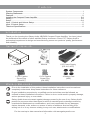
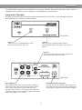
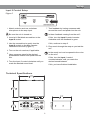
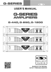
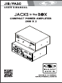
USER'S MANUAL
Contents
System Components..................................................................................................................... 1
Warning Statements...................................................................................................................... 1
Features........................................................................................................................................ 2
Installing the Compact Power Amplifier...................................................................................... 3-4
Wiring......................................................................................................................................... 3-4
Setup...........................................................................................................................................3-4
Input 1 Control and Volume Setup................................................................................................ 5
Input 2 Control Setup.................................................................................................................... 6
Technical Specifications................................................................................................................ 6
Introduction
Thank you for choosing the Galaxy Audio JIB/PA50 Compact Power Amplifier. You have joined
the hundreds of thousands of other satisfied Galaxy customers. Since 1977 Galaxy Audio’s
professional experience in design and manufacturing ensure our products' quality, performance
and reliability.
System Components
1 JIB/PA50
1 4-Pin Captive
Screw Plug
(CN-4SP)
Manual
1 3-Pin Captive
Screw Plug
(CN-3SP)
1 DC Power Supply
(PS-19-3.45.5)
4 Rubber Feet
(HRF)
Warning Statements
Prior to the installation of this product, these installation instructions must be read and
completely understood. Keep these instructions for future reference.
Proper installation procedure by a qualified service technician must be followed, as
outlined in these installation instructions. Failure to do so could result in property damage,
serious personal injury, or even death.
Galaxy Audio does not warrant against damage caused by the use of any Galaxy Audio
product for purposes other than those for which it was designed or damage caused by
unauthorized attachments or modifications, and is not responsible for any damages,
claims, demands, suits, actions or causes of action of whatever kind resulting from,
arising out of or in any manner relating to any such use, attachments or modifications.
For the most up to date manual and information visit www.galaxyaudio.com.
1
Features
The JIB/PA50 Compact Power Amplifier is an energy-efficient, 50amp Energy Star rated® Class-D
amplifier and is perfect for the classroom or meeting room environment.
Automatic Standby
Standby mode activates if no input signal is detected for 20 minutes. Once an input signal is
detected the unit resumes normal function.
Front View
Input 1
Input 2
Use the Input 1 potentiometer on the
front panel to control the gain.
Use the Input 2 potentiometer on the
front panel to control the gain on the input 2
signal.
Input 2
The mono sound will be evenly mixed into
the left and right amp channels.
Back View
Input Mixing
External Volume Control
The JIB/PA50 has two line-level stereo inputs on
RCA connectors plus one line-level stereo input
on a 3.5mm mini-jack and one sub-line level
(30 mV) mono input on a TRS (3.5mm) mini-jack.
Input switching is not needed All signals are mixed
inside the amp at a 1:1:1 ratio.
You can plug in an optional 10k volume pot.
The external volume control only adjusts the
mixed Input 1 signals, not the Input 2 signal.
2
Installing the Compact Power Amplifier
Wiring Step 1
If you are connecting the sound sources directly to the projector, follow the suggested
Option A wiring diagram (Figure 1) for reference.
If you are connecting the sound sources directly to the JIB/PA50 Power Amp and are
using the external volume control, follow the suggested Option B wiring diagram (Figure 2)
and 10k Pot Volume Wiring Diagram (Figure 3) for reference.
Figure 1
L
PC
VGA
Audio
Input 1
PROJECTOR
Video
DVD Audio
JIB/PA50
Input 2
R
Wireless
Mic Receiver
Variable Audio Output
Projector Remote
Volume Control
Figure 2
Input 1
L
Audio
PC
VGA
JIB/PA50
PROJECTOR
Video
DVD Audio
Input 2
R
Wireless
Mic Receiver
Line Input
Optional 10k Pot
Volume Control
Figure 3
VOLUME
10k Pot Volume
Wiring Diagram
Pot Volume
10K Ohm
10V (Pin 1)
Vol/Mute (Pin 2)
GND (Pin 3)
3
Installing the Compact Power Amplifier
Step 2
1. Use standard RCA connectors and/or 1/8"
(3.5mm) mini-cables to connect the input
devices (e.g., the projector, other audio sources)
to the power amp.
Match the wiring polarity. For example, red
for positive, black or white for negative.
Make sure no wire strand bridges (shorts)
the adjacent terminals.
3. Insert the captive screw plug into the
receptacle on the amp’s rear panel
(see drawing).
4. Attach the power amp plug to the
amplifier.
Do you need to wire the 10k pot
volume? If Yes, proceed to Step 3
below
2. Insert all four wires on each speaker into the
blue 4-pin captive screw plug supplied with the
power amp.
Use a #1 Phillips screwdriver to tighten the
locking screws.
Amp Receptacle for the
Blue 4-Pin Captive
Screw Plug
Step 3
When wiring the 10V, Vol/Mute and GND
outputs, strip off the insulation from the
external volume control wire by 3/16". Make
sure the wire ends do not touch. Keep
exposed wire ends short after stripping. If the
wires touch, they may short the amp.
1. Follow the 10k Pot Volume Wiring Diagram
to connect the external volume control to the
amp (Figure 4).
Figure 4
Use a #1 flat blade screwdriver to
tighten the locking screws.
3. Insert the captive screw plug into the
receptacle on the amp’s rear panel
(Figure 5).
Figure 5
10k Pot Volume
Wiring Diagram
Pot Volume
10K Ohm
2. Insert all three pins from the external
volume control into the green 3-pin
captive screw plug supplied with the
amp (see drawing).
VOLUME
10V (Pin 1)
Vol/Mute (Pin 2)
GND (Pin 3)
Amp Receptacle for the
Green 3-Pin Captive
Screw Plug
4
Setup
Input 1 Control and Volume Setup
Figure 6
If you are using the Option A wiring
method of installation on page 3, do the
following:
If you are using the Option B wiring
method of installation on page 3, do the
following:
1. Insert a #1 flat blade screwdriver to the
Input 1 control.
1. Insert a #1 flat blade screwdriver to the
Input 1 control.
2. To test the volume, use the screwdriver to
gently turn the Input 1 control on the amp
counter-clockwise to the end (Figure 6).
2. To test the volume, use the screwdriver to
gently turn the Input 1 control on the amp
counter-clockwise to the end (Figure 6).
3. Turn Input 1 control clockwise 1/4 turn.
3. Turn the Input 1 control clockwise 1/4 turn.
4. Play sound from the loudest audio source
input on the projector to help adjust the
amp volume.
4. Turn the 10k pot volume to the maximum
level.
5. Play sound through all the audio inputs on
the amp.
5. Turn the Input 1 control on the amp
clockwise slowly until the sound distorts.
6. Choose the loudest audio source to help
adjust the amp volume.
6. Turn the Input 1 control counter-clockwise
until the distortion disappears.
7. Adjust the projector volume until you reach
the desired sound level.
7. Turn the Input 1 control on the amp
clockwise slowly until the sound distorts.
8. Turn the Input 1 control counter-clockwise
until the distortion disappears.
9. Adjust the 10k pot volume until you reach
the desired sound level.
After setting up the Input 1, let the sound
continue to play and proceed to the “Input
2 Setup” section on page 6.
5
Setup
Input 2 Control Setup
Figure 7
7. Test feedback by having someone walk
around the room and speak into the mic.
1. Attach a device such as a wireless
microphone to the amp input.
Be sure the mic is turned on.
Is there feedback coming from the mic?
2. Insert a #1 flat blade screwdriver to the
Input 2 control.
If Yes, turn the Input 2 control counterclockwise until the feedback is gone.
3. Use the screwdriver to gently turn the
Input 2 control on the amp counterclockwise to the end (Figure 7).
If No, continue to step 8.
8. Play music through the amp as you test the
mic.
4. Turn on the mic receiver, if applicable.
Is the music too loud compared to the voice
on the mic?
5. Have someone stand in the desired
presentation location and speak into the
mic.
If Yes, turn the Input 1 control
counterclockwise until you reach the
desired sound balance.
6. Turn the Input 2 control clockwise until you
reach the desired sound level.
If No, you have finished installation.
Technical Specifications
4.29"
108.97
3.10"
78.64
3.10"
78.64
1.62"
41.15
6
THREE YEAR LIMITED WARRANTY
WARRANTY Information can be viewed online at
http://www.galaxyaudio.com/warranty.php
USER'S MANUAL
Specifications in this manual are subject to change without notice.
For the most up to date manual and information
visit www.galaxyaudio.com.
1-800-369-7768
www.galaxyaudio.com
© Copyright Galaxy Audio 2013
Printed in Taiwan
V08122013