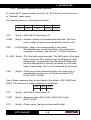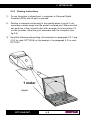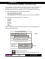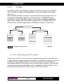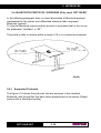
1
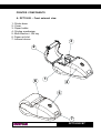
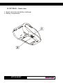
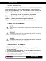
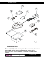
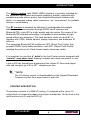
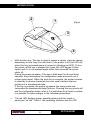
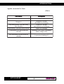
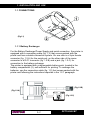
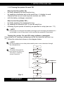
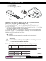
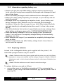
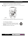
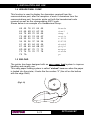
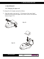
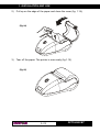
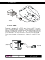
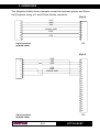
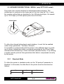
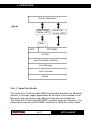
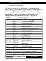
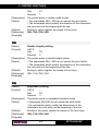
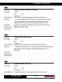
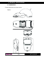
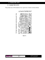
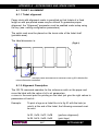
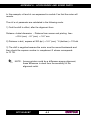
User Manual Portable thermal printer s’print www.custom.it DPT100-B/I/BT All rights reserved. Total or partial reproduction of this manual in whatever form, whether by printed or electronic means, is forbidden. While guaranteeing that the information contained in it has been carefully checked, CUSTOM ENGINEERING SPA and other entities utilized in the realization of this manual bear no responsibility for how the manual is used. Information regarding any errors found in it or suggestions on how it could be improved are appreciated. Since products are subject to continuous check and improvement, CUSTOM ENGINEERING SPA reserves the right to make changes in information contained in this manual without prior notification. COD. DOME-DPT100-B Rev. 300 Copyright 2001 CUSTOM ENGINEERING SPA – Italy CUSTOM ENGINEERING SPA Str. Berettine 2 - 43010 Fontevivo (PARMA) - Italy Phone: +39 0521-680111 Fax: +39 0521-610701 http:\\www.custom.it http:\\www.smice.com Customer Service Dept.: Phone: +39 0521-680163 E-mail: [email protected] DPT100-B/I/BT Fax: +39 0521-680146 PRINTER COMPONENTS A. DPT100-B – Front external view 1- Printer base 2- Cover 3- Paper holder 4- Printing mechanism 5- Multi-function + ON key 6- Paper exit slot 7- Infrared device 3 2 6 1 4 5 7 DPT100-B/I/BT B. DPT100-B – Under view 1- Serial connector and battery recharger 2- Battery compartment 1 2 DPT100-B/I/BT TABLE OF CONTENTS INTRODUCTION MANUAL CONTENTS .................................................................................... 1 EXPLANATORY NOTES USED IN THIS MANUAL ...................................... 1 GENERAL SAFETY INFORMATION ............................................................. 1 UNPACKING THE PRINTER ......................................................................... 2 PRINTER FEATURES ................................................................................... 3 PRINTER DESCRIPTION ............................................................................. 4 1. INSTALLATION AND USE 1.1 CONNECTIONS ................................................................................... 1-1 1.1.1 Battery recharger ........................................................................... 1-1 1.1.2 Turning the printer On and Off ....................................................... 1-2 1.2 BATTERIES ......................................................................................... 1-3 1.2.1 Recharging batteries ...................................................................... 1-3 1.2.2 Information regarding battery use .................................................. 1-4 1.2.3 Replacing batteries ........................................................................ 1-4 1.2.4 Disposing of batteries .................................................................... 1-6 1.3 CONFIGURATION ............................................................................... 1-7 1.3.1 Configuration Mod. DPT100-B/I .................................................... 1-7 1.3.2 Configuration Mod. DPT100-BT .................................................... 1-8 1.4 HEXADECIMAL DUMP .......................................................................1-11 1.5 SIXLOAD .............................................................................................1-11 1.6 MAINTENANCE.................................................................................. 1-12 1.6.1 Changing the paper roll ................................................................ 1-12 1.6.2 Cleaning ....................................................................................... 1-14 2. INTERFACES 2.1 RS232 SERIAL .................................................................................... 2-1 2.2 INFRARED BIDIRECTIONAL SERIAL ............................................... 2-4 2.2.1 Standard Mode............................................................................... 2-4 2.2.2 InfraRed communication protocol.................................................. 2-6 2.2.1 Printing instructions ........................................................................ 2-8 2.3 IrDA PROTOCOL OVERVIEW ........................................................... 2-9 2.3.1 IrDA Data protocols supported .................................................... 2-10 2.3.1.1 Physical signal layer (PHY) .................................................... 2-10 2.3.1.2 IrLAP ...................................................................................... 2-10 i DPT100-B/I/BT TABLE OF CONTENTS 2.3.1.3 IrLMP ..................................................................................... 2-12 2.3.1.4 Link Management-Information Access Service ..................... 2-12 2.3.1.5 IrCOMM ................................................................................. 2-13 2.3.1.5.1 3-Wire Raw and IrLPT in detail ............................................ 2-13 2.3.1.5.2 How 3-Wire Raw and IrLPT differ ....................................... 2-14 2.3.1.5.3 IAS entry and hint bits .......................................................... 2-14 2.3.1.5.4 Basic link operation .............................................................. 2-15 2.4 BLUETOOTH PROTOCOL OVERVIEW (ONLY MOD. DPT100-BT)2-16 2.4.1 Protocols supported .................................................................... 2-16 2.4.1.1 Serial Port Profile ................................................................... 2-17 2.4.1.2 Object Push Profile ................................................................ 2-18 3. PRINTER FUNCTIONS 3.1 CONTROL CHARACTERS .................................................................. 3-1 3.1.1 Emulation ...................................................................................... 3-1 4. TECHNICAL SPECIFICATIONS 4.1 TECHNICAL SPECIFICATIONS ......................................................... 4-1 4.2 ADAPTOR SPECIFICATIONS ............................................................ 4-4 4.3 DIMENSIONS ....................................................................................... 4-4 5. CHARACTER FONTS 5.1 CHARACTER SETS ............................................................................ 5-1 APPENDIX A - ACCESSORIES AND SPARE PARTS A.1 TICKET ALIGNMENT .......................................................................... A-1 A.1.1 Ticket alignment ............................................................................. A-1 A.1.2 Alignment Description ................................................................... A-1 A.2 ACCESSORIES................................................................................... A-3 A.2.1 Belt coupler.................................................................................... A-3 A.3 SPARE PARTS .................................................................................... A-3 DPT100-B/I/BT ii INTRODUCTION MANUAL ORGANIZATION In addition to the Introduction which includes a description of the explanatory notes used in the manual, general safety information, how to unpack the printer and a brief description of the printer including its basic features, this manual is organized as follows: Chapter 1: Contains the information required for correct printer installation and its proper use, as well as interface specifications Chapter 2: Contains information on interface specifications Chapter 3: Contains a description of the printer command set Chapter 4: Contains Technical Specifications of the printer Chapter 5: Contains the character sets (fonts) used by the printer SYMBOL USED IN THIS MANUAL NOTE Gives important information or suggestions relative to the use of the printer. WARNING Information marked with this symbol must be carefully followed to guard against damaging the printer. DANGER Information marked with this symbol must be carefully followed to guard against operator injury or damage. GENERAL SAFETY INFORMATION • Read and keep the instructions which follow. • Before cleaning the printer, disconnect the power supply and make sure that the printer is off. • Clean the printer with a damp cloth. Do not use liquid or spray products. • Do not operate the printer near water. • Only use approved accessories and batteries. Do not connect to products that are not compatible. 1 DPT100-B/I/BT INTRODUCTION • Use the type of electrical power supply indicated on the printer label. If in doubt, contact your retailer. • When deciding where to place the printer, make sure it is positioned where its cables will not be damaged. • Do not introduce foreign objects of any kind into the printer as they could cause a short circuit and could jeopardize printer functioning. • Do not spill liquids onto the printer. • Do not carry out technical operations on the printer, with the exception of the scheduled maintenance procedures specifically indicated in the user manual. • Disconnect the printer from the electricity supply and have it repaired by a specialized technician when: A. The feed connector has been damaged. B. Liquid has seeped inside of the printer. C. The printer has been exposed to rain or water. D. The printer is not functioning normally despite the fact that all instructions in the users manual have been followed. E. The printer has been dropped and its outer casing damaged. F. Printer performance is poor. G. The printer is not functioning. UNPACKING THE PRINTER Remove the printer from its carton being careful not to damage the packing material so that it may be re-used if the printer is to be transported in the future. Make sure that all the components illustrated in fig. 1 are present and that there are no signs of damage. If there are, contact Customer Service. 1. 2. 3. 4. 5. 6. 7. 8. Warning sheet Cable Paper roll Adaptor / Battery recharger Batteries (5 pcs.) Belt coupler Printer Box DPT100-B/I/BT 2 INTRODUCTION 1 2 4 3 s’p r in t 7 5 8 6 (Fig. 1) PRINTER FEATURES The new s’ print portable thermal printer offers an innovative alternative to impact-based systems, with a range of interface options (RS232 serial,R232+IRDA, RS232+Bluetooth). The printer is powered using batteries. 3 DPT100-B/I/BT INTRODUCTION The battery version (with RS232+IRDA interface) is primarily intended for the automatic identification and mobile telephony market, combined with portable terminals without printer; the infrared bidirectional interface with which it is equipped makes cable connection—so “inconvenient” for portable devices—unnecessary. The BT version is powered by batteries (5 rechargeable AA penlight batteries), and communicates through RS232 serial interface and Bluetooth(TM). s’print-BT is a light weight and slim printer. By means of the Bluetooth(TM) wireless technology it is capable to print wireless at high speed without any alignment. The ideal and best match of s’print-BT is together with PDAs, mobile phones, laptop computers, and automatic ID devices. The supported Bluetooth(TM) profiles are SPP (Serial Port Profile) that provides RS232 serial cable emulation, and OPP (Object Push Profile) enabling the print-out of vCard format objects (business cards). It is important to note that s’ print is the first Custom printer designed with “sixload” easy paper load, making it simpler and more convenient to use. It has a 203 dpi thermal print mechanism that utilizes 57.5mm-wide paper rolls and can print up to 24 o 40(1) charaters per line. NOTE The 40 column version is downloadable on the Support/Download/ Firmware section from www.custom.it web site. (1) PRINTER DESCRIPTION The printers consists of a ABS-V0 casing (1) equipped with a cover (2) under which is housed the paper roll and print mechanism. On the front is the multi-function key (3) and red LED (4). DPT100-B/I/BT 4 INTRODUCTION 2 1 (Fig. 2) 3 4 • Multi-function key. This key is used to access a variety of printer options depending on how long it is held down. If the printer is off (red LED off), when this key is pressed power is turned on (blinking red LED). To turn the printer off the key is pressed two times (the LED begins to blink faster) and if it is not pressed again within three seconds the printer shuts off. During the power-up phase, if the key is held down for at least three seconds, the printer enters the configuration mode and prints out a printer setup report. When the print-out is complete, the printer remains in stand-by to receive characters from the serial interface that are printed out in hexadecimal code. If the key is pressed, the printer by-passes the setup mode and terminates the hexadecimal dump function. Pressing the key quickly will exit the configuration mode, while if it is held down for at least a second, it is possible to make changes in the individual parameters. • The red LED displays printer operating status and this check is performed “on-line”. Table 1 lists operating statuses and the LED 5 DPT100-B/I/BT INTRODUCTION signals connected to them: (Tab.1) LED status Description Always off Printer off Always on Printer on - no fault with batteries recharging Very slow blinking (one blink every three seconds) Printer On - no fault with batteries not recharging Slow blinking (one blink every second) Paper Out message Fast blinking (one blink every half second) Resettable error (head overheating, battery voltage error) Very fast blinking (seven blinks per second) In process of shutting off DPT100-B/I/BT 6 1. INSTALLATION AND USE 1.1 CONNECTIONS 1 (Fig.1.1) 2 1.1.1 Battery Recharger For the Battery Recharger/Power Supply and serial connection, the printer is equipped with a connecting cable (fig. 1.2) that comes packed with the printer and has a double connection system. On one side is a 9-pin female connector (fig. 1.2.A) for the serial port; on the other side of the same connector is a RJ11 connector (fig. 1.2.B) and a jack (fig. 1.2.C) for connection to the battery recharger. The printer is equipped with a rechargeable battery pack, located in the battery compartment (2), self-sufficient for printing. To recharge the batteries, use the connection cable (fig. 1.2) that comes packed with the printer and following the instructions reported in the 1.2.1 paragraph. (Fig.1.2.B) (Fig.1.2.A) DC IN (Fig.1.2.C) 1- 1 DPT100-B/I/BT 1. INSTALLATION AND USE 1.1.2 Turning the printer On and Off • How to turn the printer On by briefly pressing the multi-function key by sending a characters set on the serial line—it is better to send characters that are not read as printer controls (ex. 0x0E) with the battery recharger connected • • • How to turn the printer Off (1) by briefly pressing the multi-function key by sending the character ESC 0 over the serial line following a given period of inactivity as specified in setup (see sec. 1.3) • • NOTE If the printer is connected to the battery recharger and it recharging the batteries it’s not possible to turn off the printer. It must wait that the operation in terminated. (1) Turning the printer On and Off using software commands If the printer is off, sending a characters set on the serial line will turn it on (2)(3) . Follow the instructions shown in the diagram below: NOTE It’s not possible to turn on the printer sending one or more characters through the infrared device. (2) START (3) NOTE The printer start up will not occur before 200-250 msec. This delay is caused by internal component. Time out = 10 sec. Transmits status command RTS is high ? Yes Printer on No Received characters from serial No No Time out = 0? Yes Printer on error (Fig.1.3) END DPT100-B/I/BT 1- 2 Yes 1. INSTALLATION AND USE 1.2 BATTERIES 1.2.1 Recharging batteries (Fig.1.4) Appearing in the printer set up print out (see sec. 1.3) is the parameter HEAD VOLT that gives the battery charge level. To recharge the batteries(4), use the cable packed with the printer and proceed as follows: • connect the battery recharger jack to the cable jack (vedi fig. 1.4) and plug the battery recharger into the electrical mains; • connect the cable RJ11 connector to the RJ11 connector located under the printer (see fig. 1.4). For a complete recharge, we recommend that the batteries be left to charge for two hours; NOTE During the recharge operation it’s not possible turning the printer off. (4) WARNING Incorrect battery recharge voltage (different from that given in tab. 1.2) could seriously damage the printer. Tables 1.1 and 1.2 provide specifications for the battery recharger PIN SIGNAL IN / OUT DESCRIPTION 1 + VRIC POWER Battery recharge 2 GND POWER Ground signal Max recharge current 0.6 A Max recharge voltage 12V - 36V 1- 3 (Tab.1.1) (Tab.1.2) DPT100-B/I/BT 1. INSTALLATION AND USE 1.2.2 Information regarding battery use • Please note that the new NiMH battery reaches maximum performance levels only after having been completely discharged and recharged at least two or three times. • Never use battery rechargers and/or batteries that are damaged or worn. • Battery life varies greatly depending, for example, on print density and the text to be printed. • Recharge times vary depending on depletion levels, type of battery and battery recharger used. Batteries may be recharged and discharged hundreds of times, but they do wear out over time. When battery life (both print and stand-by) is noticeably shorter than usual, it is time to buy a new battery. • Only utilize batteries that conform to specifications and only recharge them using battery rechargers approved by CUSTOM ENGINEERING SPA. • When the battery recharger is not in use, unplug it from the electrical mains. If not used, even a completely-charged battery will automatically discharge over time. • NiMH batteries last longer if you remember to completely discharge them every so often. • Extreme temperatures can affect battery charge levels—leave them to cool or warm as required. 1.2.3 Replacing batteries Instead of the rechargeable battery pack supplied with the printer, 5 AA ALKALINE penlight batteries may be used(5)(6). Note: if batteries other than those supplied with the printer are used, the Battery parameter in setup must modified and the settings changed to Alkaline if Alkaline batteries are used, or the to closest reference value for other types of batteries (see sec. 1.3). (5) (6) Note: if Alkaline batteries are used it doesn’t make the recharge. To replace batteries, proceed as follows: • remove the cover on the battery compartment (1) by unscrewing the screws (2) and, using a flat-head screwdriver, pry open at points A and B (see fig.1.5). DPT100-B/I/BT 1- 4 1. INSTALLATION AND USE A B 2 1 (Fig.1.5) • remove the battery pack (2) by lifting the battery removal tape (1) (see fig. 1.6). 2 1 (Fig.1.6) 1- 5 DPT100-B/I/BT 1. INSTALLATION AND USE • insert the 5 batteries(7) inside the compartment following the layout indicated in fig. 1.7 and re-position the battery removal tape; Note: when inserting the batteries, make sure the + and – signs are positioned correctly. (7) (Fig.1.7) • reclose the battery compartment by tightening the fastening screws. 1.2.4 Disposing of batteries • • Batteries must be recycled or disposed of properly. Do not throw batteries away as part of normal refuse disposal. Do no throw batteries into open flame! DPT100-B/I/BT 1- 6 (Fig.1.8) 1. INSTALLATION AND USE 1.3 CONFIGURATION 1.3.1 Configuration Mod. DPT100-B/I The printer set up print out (see fig. 1.9) includes a range of information, and among these should be pointed out the HEAD VOLT parameter that indicates the battery charge level, i.e., the print head battery voltage. * SETUP DEFAULT * (Fig.1.9) HEAD TEMP. [°C] BATT TEMP. [°C] HEAD VOLT [V] = 22.5 = 25.0 = 6.3 Interface IR Protocol Baud Rate Data length Parity Handshaking Autofeed Battery Standby Alignment Print Density :RS232 :Enable : 9600 bps : 8 bits/chr : None : Xon/Xoff : CR disabled : 1600 mAh : 5 MIN : Disable :0 [PUSH] ENTER SET-UP [FAST PUSH] EXIT SET-UP The printer’s configurable parameters are: • Interface: RS232D, Infrared(8). • IR Protocol(9): Enable, DisableD. • Baud Rate: 38400, 19200, 9600D, 4800, 2400, 1200, 600. • Data length: 7, 8D bits/car. • Parity: NoneD, even or odd. • Handshaking: XON/XOFFD or Hardware(10). • Autofeed: CR deactivatedD or CR activated. • Battery: 1000 mAh, 1100 mAh, 1200 mAh, 1300 mAh, 1400 mAh, 1500 mAh, 1600 mAh, 1700 mAh, 1800 mAh, 1850 mAhD , Alkaline(11). • Standby: 1min, 5minD, 10 min, 30 min(12), 1 h, 2h, None. • Alignment: DisableD, Enable. • Print density: -2, -1, 0D, +1, +2. 1- 7 DPT100-B/I/BT 1. INSTALLATION AND USE Please note: the parameters marked with the symbol values. D represent the default Note If the Interface parameter is set in infrared and flow control is required, any time a transmission is effected a time break of one time and a half the byte transmission is needed (for example 1.5 msec at 9600 bps). The reason is for Half Duplex type of infrared line communication. As a result the Busy condition check must be waited when transmitting data to the printer. If said condition would slow down print-out, it is alternatively possible to transmit the bytes to be printed in fixed length blocks (for example 16 bytes at a time) and to wait for the necessary time to receive a likely XON/XOFF. (8) Note The “IR Protocol” parameter is visualizzato only if interface is set in“Infrared”. (9) Note It is not possible to modify the "flow control" parameter if interface is set in infrared because it is automatically set in XON/XOFF. (10) Note This parameter regulates battery recharge time. If set to Alkaline, battery recharge is disabled. If another type of battery other than those supplied with the printer is used, select the closest appropriate charge value from the list. (11) Note This parameter regulates the period of inactivity after which the printer shuts off automatically to avoid battery discharge. (12) Each time the key is pressed quickly, the parameter will change and the current value will be printed out. Once the desired value has been attained, hold the key down for at least a second to pass to the next parameter, and so on. Printing out of a new printer set up report indicates that set up is complete. 1.3.2 Configuration Mod. DPT100-BT The printer set up print out (see fig. 1.10) includes a range of information, and among these should be pointed out the HEAD VOLT parameter that indicates the battery charge level, i.e., the print head battery voltage. DPT100-B/I/BT 1- 8 1. INSTALLATION AND USE * SETUP DEFAULT * (Fig.1.10) BT TEST = OK BT NAME = S’print-BT(12) BT PIN(13) = 12345 HEAD TEMP. [°C] = 22.5 BATT TEMP. [°C] = 25.0 HEAD VOLT [V] = 6.3 Interface BT Name ID(14) Authenticat(15) Autofeed Battery Standby Print Mode Alignment Print Density :BT :NO ID :Disabled :CR disabled :1850 mAh :5 MIN :Normal :Disable :0 [PUSH] ENTER SETUP [FAST PUSH] EXIT The printer’s configurable parameters, with Bluetooth interface selected, are: • Interface: BTD, RS232. • BT Name ID(14): NO IDD, #0, #1, #2, #3, #4, #5, #6, #7, #8, #9. • Authentication(15): Enabled, DisabledD. • Autofeed: CR disabledD o CR enabled. • Battery: 1000 mAh, 1100 mAh, 1200 mAh, 1300 mAh, 1400 mAh, 1500 mAh, 1600 mAh, 1700 mAh, 1800 mAh, 1850 mAhD , Alkaline(10). • Standby: 1min, 5minD, 10 min, 30 min, 1 h, 2h, None. • Print mode: NormalD, revers. • Alignment: DisableD, Enable. • Print density: -2, -1, 0D, +1, +2. The printer’s configurable parameters, with RS232 interface selected, are: • • • • • • • Interface: RS232D, Infrared(8). IR Protocol(9): Enable, DisableD. Baud Rate: 38400, 19200, 9600D, 4800, 2400, 1200, 600. Data length: 7, 8D bits/car. Parity: NoneD, even or odd. Handshaking: XON/XOFFD or Hardware(10). Autofeed: CR deactivatedD or CR activated. 1- 9 DPT100-B/I/BT 1. INSTALLATION AND USE • Battery: 1000 mAh, 1100 mAh, 1200 mAh, 1300 mAh, 1400 mAh, 1500 mAh, 1600 mAh, 1700 mAh, 1800 mAh, 1850 mAhD , Alkaline(11). • Standby: 1min, 5minD, 10 min, 30 min(12), 1 h, 2h, None. • Alignment: DisableD, Enable. • Print density: -2, -1, 0D, +1, +2. Please note: the parameters marked with the symbol values. D represent the default (12) NOTE: It’s the name that identify the printer from a Bluetooth remote device. (13) NOTE: BT PIN is the password that permit to connect to the printer, if some devices request it. (14) NOTE: BT Name ID needs to diversify one printers from another that have the same name, inside the same area. The index will be added at the end of the name (example: S’print-BT #1). It’s possible that some Bluetooth remote device don’t update immediatly printer name, but only at the beginning of new connection. This happened because most of remote devices create a page table between Bluetooth address (that is passed on every access) and the identification name. So the method of research of remote devices is sensibly faster, but it involves that the printer name (or others devices BT) is update only sometimes, for the most part it happened at the beginning of new connection. (15) NOTE: Nota the authentication needs to enable the password entry, from the host at every connection, for printing. This option activation allows to print even if sameone isn’t enable to do it . If sameone is enable to use the printer (and consequenty to know the password), it’s possible to execute an operation of “pairing” (combination of the devices) in this operation the password is requested only one time. It’s possible, when the devices are coupled, to access to printing service without password. The BT name, BT PIN, BT name ID and the authentication become actives only turning off and than turning on the printer, reset commands or reset after set up don’t get actives those setting. If Bluetooth is enable, it’s better do not send data on RS232 line, because datas could set over Bluetooth line. DPT100-B/I/BT 1- 10 1. INSTALLATION AND USE 1.4 HEXADECIMAL DUMP This function is used to display the characters received from the communications port; after the reception of each 6 characters from the communications port, the printer prints out both the hexadecimal code received as well as the corresponding ASCII code. Shown below is an example of a Hexadecimal Dump: 48 63 64 75 6E 34 61 67 6D 73 79 65 69 75 6E 20 35 62 68 6E 74 7A 78 6D 6D 63 30 36 63 69 6F 75 61 61 70 74 31 37 64 6A 70 76 64 6C 20 69 32 38 65 6B 71 77 65 20 66 6F 33 39 66 6C 72 78 Hexade cimal dump f unctio n 0123 456789 abcdef ghijkl mnopqr stuvwx yz 1.5 SIXLOAD The printer has been designed with an easy paper load system to improve handling and simplify use. This easy paper loading system is called “sixload” because when the paper is loaded into the printer, it looks like the number “6” (the roll on the bottom with the edge lifted). (Fig.1.11) 1- 11 DPT100-B/I/BT 1. INSTALLATION AND USE 1.6 MAINTENANCE 1.6.1 Changing the paper roll To change the roll of paper, proceed as follows: 1) Open the printer cover (see fig. 1.12) levering on the cover lateral projections and position the paper roll so that it unrolls in the direction shown in figure 1.13; (Fig.1.12) (Fig.1.13) DPT100-B/I/BT 1- 12 1. INSTALLATION AND USE 2) Pull up on the edge of the paper and close the cover (fig. 1.14); (Fig.1.14) 3) Tear off the paper. The printer is now ready (fig.1.15). (Fig.1.15) 1- 13 DPT100-B/I/BT 1. INSTALLATION AND USE 1.6.2 Cleaning To clean the printer, use a vacuum cleaner or soft cloth. Before cleaning the printer, unplug its electrical cord and make sure that the printer is off. Do not use alcohol, solvents or hard-bristled brushes. Do not let water or other liquids seep into the printer. alcohol, solvent (Fig.1.16) DPT100-B/I/BT 1- 14 2. INTERFACES (Fig.2.1) 2.1 RS232 SERIAL The printer is equipped with an RS232 serial interface with RJ11 connector (fig. 2.1) located underneath the printer. For serial connection, a connecting cable (fig. 2.2) with double connection system is packed with the printer. On one side is a 9-pin female connector (fig. 2.2A) to connect to the serial port; on the other side of the same connector is a RJ11 connector (fig. 2.2.B). For the layout of signals on the connectors, please refer to tables 2.1 and 2.2. (Fig.2.2.A) (Fig.2.2.B) 2- 1 DPT100-B/I/BT 2. INTERFACES RJ11 connector DPT100 (fig. 2.1) (Tab.2.1) PIN SIGNAL IN/OUT A DESCRIPTION 1 +VRIC IN - Battery recharge voltage 2 GND - GND Ground signal 3 RX IN TXD Receive data 4 TX OUT RXD Transmit data 5 RTS OUT CTS Ready to send / Ready to receive data 6 GND - GND Ground signal (Tab.2.2) 9-pin female connector (fig. 2.2.A) PIN SIGNAL IN/OUT A DESCRIPTION 1 DCD OUT DCD Data carrier identification. Printer On (active at RS232 high) 2 TXD OUT RXD Transmit data. Serial output (from host) 3 RXD IN TXD Receive data. Serial data input (to host) 4 N.C. - N.C. Not connected 5 GND - GND Ground signal 6 D SR OUT D SR Data set ready. Printer ON and operating (active at RS232 high) 7 N.C. - N.C. Not connected 8 RTS OUT CTS Ready to send / Ready to receive data (active at RS232 high) 9 N.C. - N.C. Not connected DPT100-B/I/BT 2- 2 2. INTERFACES The diagrams below show a sample connection between printer and Personal Computer using a 9- and 25-pin female connector. (Fig.2.2) 1 2 3 4 5 6 7 8 DCD RXD TXD 1 2 SIGNAL GND DSR 5 CTS 9 3 4 6 7 8 9 9-pin connector (s’print cable) PC (Fig.2.3) DCD TXD RXD 1 2 3 4 CTS DSR SIGNAL GND 5 6 7 8 9 9-pin connector (s’print cable) 1 2 3 4 5 6 7 8 9 10 11 12 13 14 15 16 17 18 19 20 21 22 23 24 25 PC 2- 3 DPT100-B/I/BT 2. INTERFACES 2.2 INFRARED BIDIRECTIONAL SERIAL (only DPT100-B model) The printer has a serial interface for bidirectional data exchange. The infrared port is centered on the lower part of the front (see fig. 2.4); it uses the encode method bits as described in the IrDA physical layer, for speeds up to 115.2 kbps (a 3/16th optical pulse time of bit time). Infrared port (Fig.2.4) To utilize the infrared bidirectional serial interface, it must first be enabled under setup (parameter: “Interface: Infrared”). It is possible to communicate with the printer in two different ways: by sending a string of characters and/or commands preceded by the IR port Open command and followed by a Close command (standard mode), or by utilizing a simple transfer protocol that guarantees that data is compressed correctly by the printer. 2.2.1 Standard Mode To utilize the printer in standard mode, set the “IR protocol” parameter to Disabled. In this mode, the data flow to the printer must be structured as follows: 2Bytes n Bytes 2Byte Start Command Dati/Comandi Stop Command DPT100-B/I/BT 2- 4 2. INTERFACES START COMMAND (ESC STX): the IR port opening command, it is composed of 2 bytes with values 0x1B 0x02. All characters received before this command, when the communication port is closed, are ignored. DATA/COMMANDS: the part of the data and/or commands the printer must elaborate and its length is variable. This field may include both data to be printed and control characters (see Section 3 “Printer Functions”). To guarantee that all data is received correctly, this field is subject to handshaking software (xon/xoff). STOP COMMAND (ESC ETX): the IR port closing command, it is composed of 2 bytes with values 0x1B 0x03. All characters received after this command are ignored, unless it is a START COMMAND. EXAMPLE: To use this protocol to print the text “CUSTOM” in double height and width, send the following data to the printer Start Command Dati Stop Command Modo espanso 0x1B 0x02 0x03 Line F eed 0x43 0x55 0x53 0x54 0x4F 0x4D C U S T O 0x0A 0x1B 0x03 M NOTE The LED is always switched on (not flashing) when using the infrared port. 2- 5 DPT100-B/I/BT 2. INTERFACES 2.2.2 InfraRed communication protocol To utilize the IR communication protocol, the “IR Protocol” must first be set to “Enabled” under setup. The transfer protocol is structured as follows: 1Byte 1Byte Lung Bytes 1Byte 1Byte STX LUNG DATI ID JOB C KS STX [1byte] = 0x02 Start Transmission ID LUNG [1byte] = number of bytes in the transmitted data field. The maximum number of bytes to be transmitted must be <=48. DATI [LUNG bytes] = data to be communicated to the printer. The datafield may include both data to be printed and command characters (see Section 3 “Printer Functions”). ID JOB [1byte] = ID of the data packet received. The 0x00 value of this data field is reserved. This number must be different for each transmission: a data packet with the same IDJOB as the previous data packet is formally accepted (an ACK message is transmitted), but it is not interpreted by the printer. CKS [1byte] = Check sum of the transmitted bytes: the check sum is calculated as an 8 bit sum of all previous fields (STX, LUNG, DATI, IDJOB) One of three responses may be sent back to the printer: ACK, NACK and BUSY. The structure of these responses is as follows: 1Byte 1Byte 1Byte STX TYPE STS STX [1byte] = 0x02 Start Transmission ID TYPE [1byte] = Response type: ACK (0x06), NACK (0x15) and BUSY (0x13)) STS [1byte] = Printer status: the byte is structured like that DPT100-B/I/BT 2- 6 2. INTERFACES Bi t 0,1 Off/On Off Hex 00 Decimal 0 On 03 3 Off 00 0 On 0C 12 Off Off On Off On Off 00 00 20 00 40 00 0 0 32 0 64 0 2,3 4 5 6 7 Function Cover close, paper present Cover open or paper sensor not working Paper-end sensor: Paper present Paper-end sensor: Paper not present Not used. Fixed to Off. Head temperature correct Head temperature error Battery voltage correct Battery voltage error Not used. Fixed to Off. An ACK response is returned in the event the entire protocol was interpreted correctly and the check sum calculated is the same as that received by the host. A NACK response is returned in the event of transmission errors that cause a discrepancy between the calculated and received check sums. A BUSY response is returned in the event the printer does not have sufficient memory to store the transmitted data. If this response is returned, use the STS byte to find the cause that generated the BUSY condition. If there are no errors (no paper, head overheating or incorrect electrical voltage), the BUSY message has been generated because the buffer is full and it is necessary to wait for the buffer to empty; then change the IDJOB field and repeat the transmission. EXAMPLE: To use this protocol to print the text “CUSTOM” in double height and width, send the following data to the printer STX LUNG Dati IDJOB CKSUM Modo espanso 0x02 0x08 0x03 Line F eed 0x43 0x55 0x53 0x54 0x4F 0x4D C U S T O M 2- 7 0x0A 0x01 DPT100-B/I/BT 0xF3 2. INTERFACES 2.2.3 Printing instructions 1) To use the printer’s infrared port, a computer or Personal Digital Assistant (PDA) with IR port is required. 2) Position a computer conforming to the specifications in point 2) not more than a meter away from the printer’s infrared port. Make sure the two ports are in front of each other with an angle of not more than 15° on the fou sides. Send the print command from the computer (see fig.2.5). 3) Send the following data printing, like descript in to paragraph 2.2.1 and 2.2.2 for mod. DPT100-B or like descript in to paragraph 2.3 for mod. DPT100-I 15° 1 meter (Fig.2.5) DPT100-B/I/BT 2- 8 2. INTERFACES 2.3 IrDA PROTOCOL OVERVIEW (only DPT100-I model) This paragraph contains a general overview information about IrDA protocol implemented on the printer. For further detrils about the complete IrDA standard specifications are available from the IrDA website www.IrDA.org. The • • • IrDA standard specifies the following protocols: Physical Signaling Layer (PHY) Lynk Access Protocol (IrLAP) Lynk Management Protocol/Information Access Service (IrLMP/IAS) The IrDA data lists optional protocols. These are: • Tiny TP • Ir Tran-P • IrOBEX • IrLAN • IrCOMM • IrMC • IrDA Lite Figure 2-6 shows the IrDA data protocol stack and which components are implemented by the printer. Printer Application IrTran-P IrObex IrLan IrMC (1) (Fig.2.6) IrComm LM-IAS Tiny Transport protocol (Tiny TP) IR Link Access Protocol (IrLAP) Asynchronous Synchronous Synchronous Serial IR 4 PPM Serial IR(2) (9600-38400b/s) (1.152Mb/s) (4 Mb/s) } IrPHY Supported by the printer Optional IrDA data protocols not supported by the 2- 9 DPT100-B/I/BT 2. INTERFACES printe Note 1: the printer implements the 3-wire Raw service class. 2.3.1 The • • • IrDA DATA PROTOCOLS SUPPORTED printer supports these required IrDA standard protocols: Physical Signaling Layer(PHY) Link Access Protocol(IrLAP) Link Management Protocol/information Access Service(IrLMP/IAS) The printer also supports some of the optional protocols for IrDA data. The optional protocols that the printer implements are: • IrCOMM 2.3.1.1 Physical Signal Layer(PHY) The printer provides the following Physical Signal Layer specification support: • Bi-directional communication • Data Packets are protected by a CRC-16-bit CRC for speeds up to 38400 kbaud • Data communication Rate -9600 baud minimum data rate (with primary speed/cost steps of 38400 baud) • Communication Range • Continuous operation from contact to at least 1 meter (typically 2 meters can be reached), all the same it’s possible in a low power devices reduce the distance at least 20 cm. 2.3.1.2 IrLAP The IrLAP protocol provides: • Management of communication processes on the link between devices. • A device-to-device connection for the reliable, ordered transfer of data. • Device discover procedures. • Hidden node handling. Figure 2-6 identifies the key parts and hierarchy of the IrDA protocols. The bottom layer is the Physical layer, IrPHY. This is the part that converts the DPT100-B/I/BT 2- 10 2. INTERFACES serial data to and from pulses of IR light. IR transceivers can’t transmit and receive at the same time. The receiver has to wait for the transmitter to finish sending. This is sometimes referred to as a “Half-Duplex” connection. The IR Link Access Protocol (IrLAP) provides the structure for packets or “frames” of data to emulate data that would normally be free to stream back and forth. (Fig.2.7) X BOFs BOF A C I (1+N) of C0h FCS Payload 2 bytes EOF C1h Figure 2-7 shows how the IrLAP frame is organized. The frame is proceeded by some number of Beginning of frame characters,(BOFs). The value of the BOF is generally 0xC0, but 0xFF may be used if the last BOF character is a 0xC0. The purpose of multiple BOFs is to give the other station some warning that a frame is coming. The IrLAP frame begins with an address byte (“A” field), then a control byte(“C” field). The control byte is used to differentiate between different types of frames and is also used to count frames. Frames can carry status, data, or commands. The IrLAP protocol has a command syntax of it’s own, and these commands are part of the control byte. Lastly, IrLAP frames carry data. This data is the information or “I” field. The integrity of the frame is ensured with a 16-bit CRC, referred to as the Frame Check Sequence (FCS). The end of the frame is marked with an EOF character which is always a 0xC1. The frame structure described here is used for all versions of IrDA protocols used for serial wire replacement for speeds up to 38400 baud. In addition to defining the frame structure, IrLAP provides the “housekeeping” function of opening and closing connections, and maintaining connections once they’ re open. The critical parameters that determine the performance of the link are part of this function. These parameters control how many BOFs are used, identify the speed of the link, how fast either party may change from receiving to transmitting, etc. IrLAP has the responsbility of negotiating these parameters to the highest common set so that both sides can communicate as fast and as reliably as 2- 11 DPT100-B/I/BT 2. INTERFACES possible. 2.3.1.3 IrLMP The IrLMP protocol provides: • Multiplexing of the IrLAP layer. This allows multiple channels above an IrLAP connection. • Protocol and service discovery. This is via the Information Access Service (IAS). When two devices that contain the IrDA standard feature are connected, there is generally one device that has something to do, and the oder device has the resource to do it. For example, a laptop may have a job to print and an IrDA standard compatible printer has the resources to print it. In IrDA standard terminology, the laptop is a Primary device and the printer is the Secondary device. When these two devices connect, the Primary device must determine the capabilities of the Secondary device to determine if the Secondary device is capable of doing the job. This determination is made by the Primary device asking the Secondary device a series of questions. Depending on the answers to these questions the Primary device may or may not elect to connect to the Secondary device. The queries from the Primary device are carried to the Secondary device using IrLMP. The responses to these queries can be found in the Information Access Service (IAS) of the Secondary device. The IAS is a list of the resources of the Secondary device. The Primary device compares the IAS responses with its requirements and then makes the decision if a connection should be made. 2.3.1.4 Link Management-Information Access Service (LM-IAS) Each LM-IAS entity maintains an information data base to provide: • Information on service for other devices that contain the IrDA standard feature (Discovery) • Information on service for the device itself • Remote accessing of another device’s information base This is required so that clients on a remote device can find configuration information needed to access a service. DPT100-B/I/BT 2- 12 2. INTERFACES 2.3.1.5 IrCOMM IrCOMM provides the method to support serial and parallel port emulation. This is useful for legacy COM applications, such as printers and modem devices. The IrCOMM standard is simply a syntax that allows the primary device to consider the Secondary device as a serial device. IrCOMM allows for emulation of serial or parallel (printer) connections of various capabilities. The printer supports the 3-wire Raw service class of IrCOMM and IrLPT. Other service classes supported by IrCOMM are shown in Figure 2-8. IrCOMM Service Uncooked Services Cooked Services Parallel Serial Parallel IrLPT 3-wire Raw Centronics IEEE 1284 Supported by printer Serial 3-wire Cooked 9-wire Cooked (Fig.2.8) 2.3.1.5.1 3-Wire Raw and IrLPT in Detail 3-Wire raw and IrLPT may be used to emulate either serial or parallel ports in cases where a single exclusiveconnection is satisfactory. They can emulate both port types because there is no control channel, and therefore no information about the non-data circuits of either type is carried - only the data normally flowing through thedata circuits is emulated. If data transfer is all a port needs to function, then 3-Wire raw or IrLPT may be fine. 2- 13 DPT100-B/I/BT 2. INTERFACES 2.3.1.5.2 How 3-Wire raw and IrLPT differ 3-Wire raw and IrLPT are two names for the same COMM emulation service. IrLPT was built into some commercially available devices before this IrCOMM specification was complete, and is included here for compatibility. There are two differences between 3-Wire raw and IrLPT: • IrLPT has a fixed definition and purpose - it is for printing only. IrCOMM 3Wire raw can be used forboth printing and non-printing tasks • 3-Wire raw uses an IAS entry with classname IrDA:IrCOMM and at least two parameters. Its IAS definition may be modified or extended over time. IrLPT has classname IrLPT, only one parameter, and the IAS definition isfixed. IAS entry formats are defined in the next section. Beyond these two distinctions, 3-Wire raw and IrLPT are the same. 2.3.1.5.3 IAS entry and hint bits An entity advertising 3-Wire raw must set up the IAS entry in one of two forms: • Classname IrDA:IrCOMM with two attributes, called IrDA:IrLMP:LsapSel, and Parameters. The Parameters attribute has at least the service type parameter with at least the 3-Wire raw bit set in it. Optionally IrDA:IrLMP:InstanceName can be used to distinguish between two instances of this service. The Discovery frame must have the IrCOMM hint bit set. It should also have the printer bit set if this is a printing service. • An alternate entry provided for backwards compatibility with some existing devices has Classname IrLPT with just one attribute, called IrDA: IrLMP :LsapSel. The printer hint bit must be set in the Discovery frame. This IAS object is only used for printing services. DPT100-B/I/BT 2- 14 2. INTERFACES 2.3.1.5.4 Basic link operation 3-Wire raw connections must be exclusive - that is, all other non-IAS connections must terminate before the raw connection is made, and all others must wait until the raw connection is broken before they can connect. This is because 3-Wire raw uses IrLAP flow control, which flow controls off the entire physical link - multiple connections under this scenario could result in deadlock. At connection, the 3-Wire raw service type can be distinguished reliably by its LSAP-SEL alone, since unlike the cooked types (where multiple service types can be referenced by IrDA:TinyTP:LsapSel) only 3-Wire raw can use the LSAP-SEL specified by IrDA:IrLMP:LsapSel. Once connected there is no control channel and no control parameters of any kind to look for - the only data that comes over 3-Wire raw is the user data that would flow over TD and RD on a serial port or the 8 data lines of a Centronics port. This means 3-Wire raw cannot be used to emulate any kind of hardware handshaking or error reporting. 2- 15 DPT100-B/I/BT 2. INTERFACES 2.4 BLUETOOTH PROTOCOL OVERVIEW (Only mod. DPT100-BT) In the following paragraph there is a brief description of Bluetooth protocol implemented in the printer and differented elements that composed Bluetooth protocol. To Use the Bluetooth communication protocol is necessary that in the set up the parameter “Interface” in “BT”. The printer is able to receive within a range of 10 m in a vacant envoirement. 10 metri 10 metri (Fig.2.9) 2.4.1 Supported Protocols The figure 2.10 shows the protocols that are previews in the standard Bluetooth, and the profiles that have been implemented in the printer (Object push profile e Serial port profile). DPT100-B/I/BT 2- 16 2. INTERFACES Printer Application (Fig.2.10) Object Push Profile (OPP) Serial Port Profile (SPP) OBEX SDP RFCOMM L2CAP Host Controller Interface Link Manager Link Controller Radio 2.4.1.1 Serial Port Profile The Serial Port Profile provides RS232 serial cable emulation for Bluetooth devices. In this way, legacy applications do not have to be modified to use Bluetooth; they can simply treat a Bluetooth link as a serial cable link. The Serial Port Profile uses RFCOMM to provide serial port emulation. The device which sets up the RFCOMM connection is called the initiator, while 2- 17 DPT100-B/I/BT 2. INTERFACES the other is referred to responder. A few passages are requested to set the virtual serial port and to establish a connection, so it is necessary. that on the side host a software management of the Bluetooth devices must manage to execute every of these passages (the search of removedevices, the optional request of the password, chanal setting RFCOMM, ecc.). 2.4.1.2 Object Push Profile L’object push profile, uses the Generic Object Exchange Profile (GOEP) services that defines 2 rules: the first is a server devices that the object can be send or receive (the printer is a server devices) and a client devices that can send or receives data objects from the server (for example: a Pc, a cell Phone, or a Palm). The Object Push Profile provides facilities for exchanging business cards between client and server, for pulling business cards from a server, and for pushing a limited range of object onto a server. The object that printer identify are: Object Format Extension Business Card VCard .VCF Text File Text .TXT Printing File Printing on File .PRN Message VMessage .VMG Note VNote .VNT Activity Object VCalendar .VCS DPT100-B/I/BT 2- 18 3. PRINTER FUNCTIONS 3.1 CONTROL CHARACTERS The command table lists all the commands for the management of the printer functions. These commands can be transmitted to the printer with the serial interface. The commands can be transmitted to the printer at any moment, but they will only be carried out when the characters previously transmitted have been printed or the commands previously transmitted have been carried out. There are no commands with priority status; all the commands are carried out when the circular buffer is free to do so. (Tab.3.1) ASCII Com. COMMAND TABLE HEX Com. Description $00 Prints in small characters $01 Prints in double width $02 Prints in double height $03 Expanded printing $04 Restores small character printing $07 Cancel print data buffer $0A Forward feeds one line (n) $0B Forward feeds (n) line $0D Prints line buffer $0F Sets CRLF mode $11 Graphic mode ESC (STX) $1B $02 Enable infrared port ESC (ETX) $1B $03 Close down the communication with infrared port ESC # n $1B $23 n Transmit printer ID ESC 0 $1B $30 Turning the printer off ESC @ $1B $40 Resets the printer ESC A $1B $41 Executes [n] dots line feed (dd) ESC M (dd) $1B $4D Writes value (dd) in print mode ESC N $1B $4E Sets normal mode printing ESC Q $1B $51 Enables underlining 3-1 DPT100-B/I/BT 3. PRINTER FUNCTIONS ASCII Com. HEX Com. Description ESC R $1B $52 Sets reverse mode printing ESC W $1B $57 Prints graphic line of 200 dpi (dd) ESC a $1B $61 Selects number of dot spaces ESC c $1B $63 Management of bar code printing ESC m $1B $6D Transmits print mode in serial ESC q $1B $71 Disables underlining ESC s $1B $73 Transmits next character in serial ESC v $1B $76 Transmits a printer status ESC ⋅ n1 n2 $1B $FA n1 n2 Print graphic GS $ n $1D $24 n Set absolute shift into a graphic line GS I n $1D $49 n Transmits the printer ID GS U $1D $55 Resets printer parameters to default value GS W n $1D $57 n Prints n byte of a 200 dpi graphic line GS ÷ (nH) (nL) $1D $F6 (nL) (nH) Aligns the ticket at the first printed line The following pages provide a more detailed description of each command. 00H [Name] [Format] [Description] [Notes] [Default] [Reference] [Example] Small character printing ASCII Hex 00 Decimal 0 The printer prints in small characters (normal) • The commands 00H - 09H do not cancel the print buffer • The commands which modify the direction of the characters are only active at the beginning of the line Setting in option register by means of front keys 01H, 02H, 03H, 04H 01H [Name] [Format] Double width printing ASCII DPT100-B/I/BT 3-2 3. PRINTER FUNCTIONS [Description] [Notes] [Default] [Reference] [Example] Hex 01 Decimal 1 The printer prints in double width format • The commands 00H - 09H do not cancel the print buffer • The commands which modify the direction of the characters are only active at the beginning of the line Setting in option register by means of front keys 00H, 02H, 03H, 04H 02H [Name] [Format] [Description] [Notes] [Default] [Reference] [Example] Double height printing ASCII Hex 02 Decimal 2 The printer prints in double height format • The commands 00H - 09H do not cancel the print buffer • The commands which modify the direction of the characters are only active at the beginning of the line Setting in option register by means of front keys 00H, 01H, 03H, 04H 03H [Name] [Format] [Description] [Notes] [Default] [Reference] [Example] Expanded printing ASCII Hex 03 Decimal 3 The printer prints in expanded character mode • commands 00H-09H do not cancel the print buffer • the commands which modify the dimensions of the characters are only active at the beginning of the line Setting in the option register by means of the front keys 00H, 01H, 02H, 04H 3-3 DPT100-B/I/BT 3. PRINTER FUNCTIONS 04H [Name] [Format] [Description] [Notes] [Default] [Reference] [Example] Restore small character printing ASCII Hex 04 Decimal 4 The printer resumes printing with small characters • The commands 00H-09H do not cancel the print buffer • the commands which modify the dimensions of the characters are only active at the beginning of the line Setting in the option register by means of the front keys 00H, 01H, 02H, 03H 07H [Name] [Format] [Description] [Notes] Cancel print data buffer ASCII Hex 07 Decimal 7 Deletes all the print data in the current print buffer. • If data that existed in the previously specified printing area also exists in the currently specified printing area, it is deleted. [Default] [Reference] [Example] 0AH [Name] [Format] [Description] Forward feeds one line ASCII Hex 0A Decimal 10 Forward feeds one line equivalent to a line of print DPT100-B/I/BT 3-4 3. PRINTER FUNCTIONS [Notes] [Default] [Reference] [Example] • This command brings about the printing of the contents of the line buffer 0BH (n) 0BH [Name] [Format] [Description] [Notes] [Default] [Reference] [Example] Forward feeds (n) lines ASCII Hex 0B Decimal 11 Carries out the number of line feeds specified in (n) •The number must be ASCII and between 0 and 9 (when n=0 the command is ignored) • This command clears the line buffer 0AH To forward feed fast, 5 lines at a time: $35 $0B (or 5 and the command $0B) 0D H [Name] [Format] [Description] [Notes] [Default] [Reference] [Example] Print the line buffer ASCII Hex 0D Decimal 13 This command prints the line buffer • If the line buffer is empty, the command is ignored • If the CRLF option is set, this command is ignored and printing can only be ordered through the command $0A 0FH 3-5 DPT100-B/I/BT 3. PRINTER FUNCTIONS 0F H [Name] [Format] [Description] [Notes] [Default] [Reference] [Example] Set CRLF mode ASCII Hex 0F Decimal 15 Inhibits the command $0D maintaining enabled only the command $0A for printing • To disable this option, reset the printer • This command clears the line buffer • On switching on the default value is in the Option Register Setting in the option register by means of the front keys 0DH 11H [Name] [Format] [Description] [Notes] Graphic mode ASCII Hex 11 Decimal 17 Enables graphic mode: a line in 24 column mode corresponds to 144 horizontal dots divided into 24 blocks of 6 dots each; a line in 40 column mode corresponds to 240 horizontal dots divided into 40 blocks of 6 dots each. To obtain graphic printing, enter the command $11 at the beginning of each line. The format of the byte in graphic configuration is: X R P6 P5 P4 P3 P2 P1 D7 D6 D5 D4 D3 D2 D1 D0 where: X is not used (0 is recommended); R must be fixed at level 1; P1,.P6 are the graphic dot data (1 prints, 0 does not print). The P6 bit of the string of dots transmitted is printed on the left and the others follow from left to right (P5, P4, P3, P2, DPT100-B/I/BT 3-6 3. PRINTER FUNCTIONS [Default] [Reference] [Example] P1) as shown: 1st byte Î 2nd byte Î 3rd byte Î P6 P5 P4 P3 P2 P1 P6 P5 P4 P3 P2 P1 P6 P5 P4 P3 P2 P1 To print a line of dots, transmit: $11, n x $7F (where n is the number of characters per line), $0D. To print an empty line, transmit: $11, $40, $0D. ESC (STX) [Name] [Format] [Description] [Notes] [Default] [Reference] [Example] Enable infrared port ASCII ESC (STX) Hex 1B 02 Decimal 27 2 Enable infrared port. • if the printer doesn’t receive this command all data sent to infrared port are ignored. • After receiving this command the infrared led is always switched on. ESC (ETX) ESC (ETX) [Name] [Format] [Description] [Notes] Close down the communication with infrared port ASCII ESC (ETX) Hex 1B 03 Decimal 27 3 Close down the communication with the infrared port . • The command is active only if the infrared communication channel has been enabled by the ESC STX command. • After the command execution the printer ignores all the characters received from the communication port until to the next ESC STX reception. 3-7 DPT100-B/I/BT 3. PRINTER FUNCTIONS • After receiving this command the infrared led is functioning, as usual. [Default] [Reference] [Example] ESC (STX) ESC # n [Name] [Format] [Range] [Description] n Transmit printer ID ASCII ESC # Hex 1B 23 Decimal 27 73 1 ≤ n ≤ 3, 49 ≤ n ≤ 51 Transmits the printer ID Printer ID n n n specified by n follows: Specification 50H (24 col) 1, 49 Printer model ID 54H (40 col) 60H (24 col Bluetooth version) 61H (40 col Bluetooth version) 2, 50 Not used Fixed on 00H 3, 51 ROM version ID Depends on version ROM (4 char) [Notes] • This command is executed when the data is processed in the data buffer. Therefore, there could be a time lag between command reception and data transmission, depending on data buffer status. [Default] [Reference] [Example] ESC 0 [Name] Turning the printer off DPT100-B/I/BT 3-8 3. PRINTER FUNCTIONS [Format] [Description] [Notes] [Default] [Reference] [Example] ASCII ESC 0 Hex 1B 30 Decimale 27 48 Turning the printer off. ESC @ [Name] [Format] [Description] [Notes] [Default] [Reference] [Example] Resets the printer ASCII ESC @ Hex 1B 40 Decimal 27 64 Cancels all the data in the print buffer and resets the printer mode, restoring the mode which was enabled at the moment of switching on • Same as hardware reset • After the command has been transmitted, 1.5 seconds elapse before the printer is enabled This can be useful during switching on in order to avoid the sending of false characters during initialization by the master device ESC A [nH] [nL] [Name] [Format] [Description] [Notes] [Default] [Reference] Executes [n] dots line feed ASCII ESC A nH nL Hex 1B 41 nH nL Decimal 27 65 nH nL Executes [n] dots line feed. 3-9 DPT100-B/I/BT 3. PRINTER FUNCTIONS [Example] (dd) ESC M [Name] [Format] [Description] [Notes] [Default] [Reference] [Example] Writes the value (dd) in the print mode ASCII dH dL ESC M Hex dH dL 1B 4D Decimal dH dL 27 77 Sets the print mode default parameters: $00 small character printing $01 double width printing $02 double height printing $03 expanded printing • The setting is stored in the EEPROM Setting by means of the front keys ESC m For double height printing, transmit: $30 $32 $1B $4D ESC N [Name] [Format] [Description] [Notes] [Default] [Reference] [Example] Set normal mode printing ASCII ESC N Hex 1B 4E Decimal 27 78 Select normal mode printing:the receipt feeds out of the printer with the printing upside down running from right to left Setting in option register by means of front keys ESC R ESC Q [Name] [Format] Enable underlined printing ASCII ESC Q DPT100-B/I/BT 3-10 3. PRINTER FUNCTIONS [Description] [Note] [Default] [Reference] [Example] Hex 1B 51 Decimal 27 81 After this command has been received, the characters are printed underlined ESC q ESC R [Name] [Format] [Description] [Notes] [Default] [Reference] [Example] Set reverse mode printing ASCII ESC R Hex 1B 52 Decimal 27 82 Selects printing in reverse mode: the receipt feeds out of hte printer with the printing in normal mode running from left to right. Setting in option register by means of front keys ESC N ESC W [Name] [Format] [Description] Prints a graphic line at 200 dpi ASCII ESC W Hex 1B 57 Decimal 27 87 After receiving this command, the printer waits for 48 bytes which correspond to an entire graphic line. In fact, 48 bytes of 8 bits each correspond to 384 dots per line. [Notes] [Default] [Reference] [Example] 3-11 DPT100-B/I/BT 3. PRINTER FUNCTIONS (dd) ESC a [Name] [Format] [Description] [Notes] [Default] [Reference] [Example] Selects the number of dot spaces ASCII (dd) ESC a Hex (dd) 1B 61 Decimal (dd) 27 97 (dd) are two ASCII characters which identify a hexadecimal byte and correspond to the number of dot lines between one print line and another 0 ESC c [Name] [Format] [Description] Management of bar code printing ASCII ESC c [code] [height] [position] [options] [length] [data] Hex 1B 63 Decimal 27 99 [ASCII code] Type of bar code I Interleved 2/5 C Code 39 B CodaBar e EAN8 E EAN13 [height] Number of dot lines in 1/8 mm. units. [position] Left hand margin, expressed in 1/8 mm. units [options] DPT100-B/I/BT 3-12 3. PRINTER FUNCTIONS bit bit 0 bit 1 bit0: check digit is not printed is printed bit3,2: HRI 0=no 1=above 2=below 3=above & below bit5,4: size 0=normal 1=double 2=triple 3=quadruple [maximum length] Interleaved 2/5 = Code 39 = CodaBar = EAN8 = EAN13 = 12 characters 10 characters 10 characters 8 characters 13 characters [data] Expressed in ASCII [Notes] [Default] [Reference] [Example] ESC m [Name] [Format] [Description] [Notes] [Default] [Reference] [Example] Transmits the print mode in serial ASCII ESC m Hex 1B 6D Decimal 27 109 Transmits the print mode configuration on the serial port • If the printer is using the parallel protocol, nothing with be transmitted Setting in the option register by means of the front keys ESC B The response is on two bytes. E.g. if you receive: $30, $32 it means that printing is in double height mode 3-13 DPT100-B/I/BT 3. PRINTER FUNCTIONS ESC q [Name] [Format] [Description] [Notes] [Default] [Reference] [Example] Disables underlined printing ASCII ESC q Hex 1B 71 Decimal 27 113 Annuls underlined printing ESC Q ESC s [Name] [Format] [Description] [Notes] [Default] [Reference] [Example] Transmits the next character in serial ASCII ESC s Hex 1B 73 Decimal 27 115 Transmits the next character it receives on the serial port If you transmit: ESC s A the last character, A, will not be printed but immediately transmitted on the serial line E S C · n1 n2 [Name] Print graphic bank ( 384 ´ 85 dots). [Format] ASCII ESC · n1 n2 Hex 1B FA n1 n2 Decimal 27 250 n1 n2 [Range] 0 £ n1, n2 £ 255 [Description] Prints the graphics bank from flash. n1 specifies the starting dot line ( 1 ÷ 85 ). n2 specifies the number of lines to print. [Notes] • If n1 + n2 > 85 the printer only prints 85 - n1 + 1 dotlines. [Default] DPT100-B/I/BT 3-14 3. PRINTER FUNCTIONS [Reference] [Example] To print the graphic bank from dotline 10 to dotline 40, send: 1BH FAH 0AH 1EH ESC v [Name] [Format] [Description] [Notes] Transmit paper sensor status ASCII ESC v Hex 1B 76 Decimal 27 118 When this command is received, transmit the current status of the paper sensor. • This command is executed immediately, even when the data buffer is full (Busy ). The status to be transmitted is shown in the table below: Bi t 0,1 Off/On Off Hex 00 Decimal 0 On 03 3 Off 00 0 On 0C 12 Off Off On Off On Off 00 00 20 00 40 00 0 0 32 0 64 0 2,3 4 5 6 7 Function Cover close, paper present Cover open or paper sensor not working Paper-end sensor: Paper present Paper-end sensor: Paper not present Not used. Fixed to Off. Head temperature correct Head temperature error Battery voltage correct Battery voltage error Not used. Fixed to Off. [Default] [Reference] [Example] 3-15 DPT100-B/I/BT 3. PRINTER FUNCTIONS GS $ n [Name] [Format] [Range] [Description] [Notes] [Default] [Reference] [Example] Set absolute shift into a graphic line. ASCII GS $ n Hex 1D 24 n Decimal 29 36 n 0≤ n ≤ 47 Set the print beginning position into a graphic line based on the current value of n that indicate the byte number of shift from left margin. • Settings outside the specified printable area are ignored. GS I n [Name] [Format] [Range] [Description] n Transmit printer ID. ASCII GS I Hex 1D 49 Decimal 29 73 1 ≤ n ≤ 3, 49 ≤ n ≤ 51 Transmits the printer ID Printer ID n n n specified by n follows: Specification 50H (24 col) 1, 49 Printer model ID 54H (40 col) 60H (24 col Bluetooth version) 61H (40 col Bluetooth version) 2, 50 Not used Fixed on 00H 3, 51 ROM version ID Depends on version ROM (4 char) [Notes] • This command is executed when the data is processed in the data buffer. Therefore, there could be a time lag between command reception and data transmission, depending on data buffer status. [Default] DPT100-B/I/BT 3-16 3. PRINTER FUNCTIONS [Reference] [Example] GS U [Name] [Format] [Description] [Notes] [Default] [Reference] [Example] Resets the printer parameters to default. ASCII GS U Hex 1D 55 Decimal 29 85 Resets the printer parameters to the default configuration. • After executing this command the printer is initialized. GS W n d1 ...dn [Name] [Format] [Range] [Description] [Notes] Prints n byte of a 200 dpi ASCII GS W n Hex 1D 57 n Decimal 29 87 n 1 ≤ n ≤ 48 0 ≤ d1 … dn ≤ 255 graphic line d1... dn d1... dn d1... dn Print n byte of a 200 dpi graphic line where : • n specifies the number of byte to print; • d1...dn specify the bytes to print. • If the bit image data input exceeds the number of dots to be printed on a line, the excess data are processed as printable characters. • d indicates the bit image data. Set a corresponding bit to 1 to print a dot, or to 0 to not print the dot. • This command is not affected by the emphasized, doublestrike, underline (etc.) print modes, except for the upsidedown mode. [Default] [Reference] 3-17 DPT100-B/I/BT 3. PRINTER FUNCTIONS [Example] For printing 12 bytes the command sequence is : 1D 57 0C FF 00 FF 00 FF 00 FF 00 FF 00 FF 00 GS GS ÷ (nH) (nL) [Name] [Format] [Description] [Note] [Reference] [Example] Aligns the ticket at the first printed line ASCII GS ÷ (nH) (nL) Hex 1D F6 (nH) (nL) Decimal 29 246 (nH) (nL) This command searches for the reference notch on the paper and aligns the ticket at the first line to be printed. nH and nL are the values of the shift to be made once the notch has been found The command is only performed if alignment is enabled under setup (see parameter) To print a logo on a ticket that is 25 mm long with the hole (or notch) at the end of the ticket, the following command must be sent: 0x1D, 0xF6, 0xFF, 0x7B 0x1B, 0xFA, 0x00, 0x55 (perform alignment) (print logo) In this example, nH and nL are expressed in module 2 so that the motor will recede. DPT100-B/I/BT 3-18 4. TECHNICAL SPECIFICATIONS 4.1 TECHNICAL SPECIFICATIONS Table 4.1 gives the main technical specifications for the model DPT 100-B/I. (Tab.4.1) Resolution 203 DPI (8 dot/mm) Paper roll siz e 57.5 mm ± 1 mm Sensors Paper out Print method Thermal (8 dot/mm) Print mode Forward , reverse, 90° Print styles Normal, double height/width, reverse, underlines, expanded Character fonts 1 (16 x 24 dot) Communication interfaces available Driver for Window s RS232 / RS232 + Bidirectional infrared 95 / 98 / me / NT / W2K Baud rate 600 to 38400 bps Print buffer 128 bytes Flash memory 32K Graphics memory 1 logo of 384 x 85 dots Print speed up to 50 mm/sec (2) Pow er suply 12-36 VDC / 0.6A (Battery recharger) 5 AA penlight (NI-MH/NI-CD/ALKALINE) Batteries Battery life (1) 100 mt. of paper Autonomy (hours) Print (1) 1h 40 min. Electrical input Print (1) 925 mA Environmental conditions 0 °C ÷ 50 °C Operating temperature Relative humidity 10-85 %Rh without condensing Storage temperature / humidity Dimensions 145.96mm x 88.18mm x 64.61mm Weight Note : -20 °C ÷ +70 °C / 10 %Rh ÷ 90 %Rh 370 gr. (without paper roll) STANDARD CUSTOM receipt and 1300 mAh battery. It depends by the battery status, the printing typology and the environment temperature. (1) (2) 4- 1 DPT100-B/I/BT 4. TECHNICAL SPECIFICATIONS Table 4.2 gives the main technical specifications for the model DPT 100-BT. (Tab.4.2) Resolution Paper roll siz e 203 DPI (8 dot/mm) 57.5 mm ± 1 mm Sensors Print method Paper out Thermal (8 dot/mm) Print mode Forward , reverse Print styles Normal, reverse, underlines, expanded Character fonts Communication interfaces available Driver for Window s Baud rate 1 (16 x 24 dot) RS232 / Bluetooth 95 / 98 / NT / 2K / XP / Library for print from PalmOS and PocketPC From 1200 to 38400 bps Print buffer 138 bytes Flash memory Graphics memory 17K 1 logo of 384 x 85 dots Print speed up to 50 mm/sec (2) Pow er suply 12-36 VDC / 0.6A (Battery recharger) Batteries 5 AA penlight (NI-MH/NI-CD/ALKALINE) Battery life (1) 100 mt. of paper Autonomy (hours) Print (1) 1h 40 min. Electrical input 925 mA Print (1) Environmental conditions 0 °C ÷ 50 °C Operating temperature Relative humidity Storage temperature / humidity Dimensions Weight Note : 10-85 %Rh without condensing -20 °C ÷ +70 °C / 10 %Rh ÷ 90 %Rh 145.96mm x 88.18mm x 64.61mm 370 gr. (without paper roll) STANDARD CUSTOM receipt and 1300 mAh battery. It depends by the battery status, the printing typology and the environment temperature. (1) (2) DPT100-B/I/BT 4- 2 4. TECHNICAL SPECIFICATIONS (Tab.4.3) 57 mm paper 12.7 cpi Number of columns 24, 40 (3) Characters (L x H mm) Normal 2x3 Double height 2x6 Double width 4x3 Double height and width 4x6 Bidirectional infrared port specifications Operating distance up to 1mt. Wave length 800-900 nm Bluetooth port specifications Operating distance up to 10 mt. Power Class device 3 Output power 1 mW (0 dBm) ISM Band (GHz) 2,400 - 2,4835 Lower Guard Band 2 MHz Upper Guard Band 3.5 MHz Available Channel 79 GFSK (Gaussian Frequency Shift Keying) Modulation Max Speed (Baseband) 1Mb/s Bluetooth profile supported SPP (Serial Port Profile) OPP (Object Push Profile) NOTE The 40 column version is downloadable on the Support/Download/ Firmware section from www.custom.it web site. (3) 4- 3 DPT100-B/I/BT 4. TECHNICAL SPECIFICATIONS LED safety The infrared port on the front of the printer conforms to Class 1 for LED devices (light-emitting diode), on the basis of international standard IEC 8251 (EN 60825-1). This device is not considered harmful, but the following precautions should be observed: • avoid direct exposure of eyes to infrared LED rays; • remember that infrared rays are not visible; • do not attempt to observe infrared LED rays with any type of optical aid. 4.2 ADAPTOR SPECIFICATIONS 220Vac Adaptor (Tab.4.4) Input specifications Input voltage 230 Vac Input frequence 50 Hz Output specifications Output voltage 18 V dc 120Vac Adaptor (Tab.4.5) Input specifications Input voltage 230 Vac Input frequence 50 Hz Output specifications Output voltage DPT100-B/I/BT 18 V dc 4- 4 4. TECHNICAL SPECIFICATIONS 4.3 DIMENSIONS R 75 Printer dimensions are shown below. 88,2 (Fig.4.1) 213,9 145,96 88,18 64,61 4- 5 DPT100-B/I/BT 5. CHARACTER SETS 5.1 CHARACTER SETS The printer has a 224-character font, a print-out of which is shown below. (Fig.5.1) 5- 1 DPT100-B/I/BT 5. CHARACTER SETS Blank page DPT100-B/I/BT 5- 2 APPENDIX A - ACCESSORIES AND SPARE PARTS A.1 TICKET ALIGNMENT A.1.1 Ticket alignment Paper stock with alignment marks is permitted so that tickets of a fixed length or with pre-printed areas may be utilized.To guarantee proper alignment, the “Alignment” parameter must be enabled under setup using the key (see: setting configuration parameters) The notch mark must be placed on the termic side of the ticket itself (printable area) . The label dimension is: (Fig.A.1) * * The listed value showed with on asterisk in the fig.A1 indicates the minum dimension controlled A.1.2 Alignment Description The GS F6 command searches for the reference notch on the paper and muve the label with the value of nH e nL parameters o move in the exact point for printing on the label just give the right values to parameters nH and nL. Example: To print a logo on a ticket like in to fig.A1 with the hole (or notch) at the end of the ticket, the following command must be sent: 0x1D, 0xF6, 0xFF, 0x7B 0x1B, 0xFA, 0x00, 0x55 A- 1 (perform alignment) (print logo) DPT100-B/I/BT APPENDIX A - ACCESSORIES AND SPARE PARTS In this example, nH and nL are expressed in module 2 so that the motor will recede. The nH e nL parameter are calculated in the following mode: 1) Find the shift to effect, after the alignment from: Distance =Label dimension - Distance from sensor end printing line= = 25.4 (mm) - 8.7 (mm) = 16.7 mm 2) Distance in dot ( express at 200 dpi ) = 16.7 (mm) * 8 (dot/mm) = 133 dot 3) The shift is negative because the motor must be moved backwards and then should be express number in complement 2 whose corresponds to FF 7B. NOTE: Among printers could be a difference among alignment, these difference is dued from the sensibility of the alignment notch. DPT100-B/I/BT A- 2 APPENDIX A - ACCESSORIES AND SPARE PARTS A.1 ACCESSORIES A.1.1 Belt coupler In the s’print-B battery model, there is a support kit available for the printer that consists of a belt and fastening screws. The figure below illustrates how the belt coupler is attached underneath the printer. (Fig.A.1) A.2 SPARE PARTS (Tab.A.2) R C T 57X 50 Roll of thermal paper BTNIMH-1.2V-1300MAH NICKEL-CADIUM AA batteries PCALI-DP-E Adapter/battery recharger CB9POLI-PLUG8 Serial cable VAGANCIO-CINT Belt loop coupler VACUSTODIA-CINT case for belt s'print A- 3 DPT100-B/I/BT