1
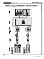
!$&78$7256
LINEAR
1000-family
2000-family
3000-family
ROTARY
1400-family
2400-family
Quintel Corporation
CONTROL3 Smartboard
Ironless-core DC Motor
Stepping Motor
Brushless DC Motor
United Technologies
Optical Systems
CONTROL2 Smartbox
Ironless-core DC Motor
Stepping Motor
!'&02725/,1($56(5926
!&21752//(56
CLOSED-LOOP
Computer Interface
Control2 Smartbox
Control3 Smartboard OEM board set
HYBRID POSITION DISPLAY
1000INT
Integrated
1000MOD
Modular
OPEN-LOOP
1200SC
Speed Controller
1200J
Joystick
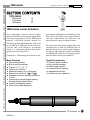
Wherever you might have used a manual
adjustment micrometer spindle, you can
substitute a motorized Linear Actuator for
computer control of movement or precise
remote manual control.
Santa Barbara Research Center
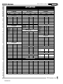
7$6.
$33$5$786
&20321(17
Point 91 sub-mirrors in Primary Mirror
HET Telescope
2200-1-AM1524-485
Point a Photographic Camera Mirror
Earth Resources Satellite
1100-05-1616-485,
1000MOD
Q6000 Photomask Aligner
1100-05-1624-485, 120005-1624-76ZB, 1200-051616-262ZB, 1200-11616-262ZB, Control3,
1200J
Position a Silicon Wafer
Direct a Mirror Forest
Position a Pressure Proximity Sensor
Position an Atomic-Force
Microscope Probe
1100-05-1616-1670-V,
1000C2-2
1200-1-1724-3.71
United Technologies
Optical Systems
Hobart Laser
Vertical Slide above sample
1100-05-1616-485ZB
Digital Instruments
Stacked X/Y/Z Slides
Position a Hybrid Memory Module
in a prototype assembly laboratory
under computer control
Translation slides
and rotating shaft
Position a Disk Head Wafer
for dicing
Quintel Corporation
Optical Table with Mirror
Mounts
Robotic End Effector
Position an Optical Fiber
in a production environment
prior to final potting
Rotate a Silicon Wafer
&86720(5
Univ. of Texas
Santa Barbara
Research Center
Rotate chuck tangent arm
Crossed-roller slide under a
grinding wheel in a wet
environment
Move a Sample
at an ultra-slow velocity
Scanning Electron
Microscope
Adjust a Valve on a Test Motor
Tangent arm rotating a
control shaft
1000-05-1624-262, 11002-1624-11.8, Control2-4,
1200-025-1616-262,
1200JC
1100-025-1616-141, 110005-1624-76, 1100-1-162422, 1100-2-1624-11.8
1100-4-1624-6.3, 1100-41624-22, 1400-1616-262
Control2-4, Control2-6
1100-025-1616-76
3M Corporation
Fiber Optics Division
Texas Instruments
Etec Corporation
1000-1-1616-3101,
Control2-2
Seagate Technology
1100-05-1624-19813ZB,
1100-1-1616-3101ZB,
1000INT
Lawrence Livermore
National Laboratory
2200-1-AM1524-41
General Motors
Power Trans. Div.
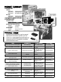
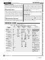
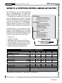
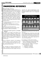
:K\XVH0RWRUL]HG/LQHDU$FWXDWRUVLQVWHDGRI
0DQXDO0LFURPHWHUVIRU$GMXVWPHQW"
! Remote control
You just can’t easily reach the knob!
! Computer control
Unattended simultaneous multi-axis motion control.
! Velocity control
Adjust the velocity profile to fit your requirement.
! Total system consolidation
Fully-computerized instruments.
! Leadscrew Pitch Error Compensation
A look-up table removes periodic pitch errors.
:KDW,QGXVWULHV8VH
0RWRUL]HG/LQHDU$FWXDWRUV"
Since automation is creeping into every
industry and personal computers sit on every
desk, our customers cross many diverse
fields )
! Semiconductor Manufacturing
Equipment
! Medical Research
! Optical/Laser Equipment
! Photographic camera pointing platform
! Satellites with optics
! Anyone adjusting a control arm
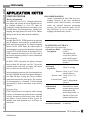
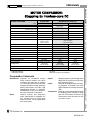
:K\XVH763URGXFWV
/LQHDU$FWXDWRUV&RPSDUHGWR
RWKHU6XSSOLHUVRI,QOLQH0RWRUL]HG$FWXDWRUV"
! Large selection of 2,374 configurations )
640 1000-series
Ironless-core DC Motor
1536
1100 and 1200-series
Stepping Motor
90
2000-series
108
2100, 2200-series
! High accuracy Leadscrew
0.5µm runout over 4"
! Long-life mechanics
• Dual anti-rotation tab to prevent
self-induced sideload on the
leadscrew.
• Zero thrust on gearhead output
shaft at limits-of-travel.
• Internal elastomer cushions at
ends-of-travel.
• Polished Nose Button ) short
radius, long radius, flat.
• Mating Push Pads.
• Bellows option for leadscrew
protection.
! Internal limit-of-travel and HOME
Hall-effect sensors with overtravel.
! High thrust up to 300 lbs. with 1724
motor and 16/7 gearhead.
! Diminished backlash option.
! One price for any gearhead ratio.
! Custom modifications easy to get.
! PULL as well as PUSH with
-PPA Push/Pull Adaptor.
! Vacuum compatibility to 10-9 Torr.
! Knowledgeable Customer Service by
product designers.
0RWRUL]HG/LQHDU$FWXDWRU$OWHUQDWLYH6RXUFHV
In-Line Motor, Low Thrust
•TS Products
•Newport/Klinger
•Oriel
•Melles-Griot
•Physik Instrumente
Side-Mount Motor,
High Thrust
•Industrial Devices
•Warner Electric
•Jordan Controls
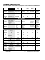
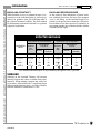
&203$5,1*7+(&203(7,7,21
In the table below, we compare selected features of our Linear Actuators to five other suppliers.
(Please verify competitors’ features.)
FEATURE
TS PRODUCTS
Basic
Construction
In-line Motor/Encoder/Leadscrew inside 1"
OD tube
Standard
Micrometer
Replacement?
Yes
Internal Limitof-Travel Sensors?
Newport/
Klinger
Similar in-line construction.
Rectangular PM500-A1
with glass scale
Yes
Oriel
MellesGriot
Burleigh
Instruments
New Focus
Similar in-line
construction
in 0.75" tube
Probably
similar
Ganged piezoelectric washers
move on rod
Clever Piezo
Motor rotates
screw by friction
Yes
Yes
Yes
No
No
No
No
No
! 850/860 No
! PM500-A1?
! 1000-family (custom)
! 2000-family (std.)
Principal Attributes
Positive
Attributes?
!
!
!
!
!
!
!
Large selection
Custom Modifications
Rugged
Open and closed-loop
OEM/quantity discounts
Fast delivery
Knowledgeable Customer
Support
Negative
Attributes?
! Open and closed loop
! Smaller OD
! Open & closed
loop
! Limited selection
! Weaker internal construction
! Limited custom modifications
! No OEM or quantity
discounts?
! Less thrust
! Weak motor
! Self-constricting
! Fragile
construction
! Variations?
?
! High-resolution
! Higher absolute
accuracy
! Zero backlash
! Small package
! High resolution
! Laser mirror
positioning
! Zero backlash
?
! Open-loop uncertainty
! High acoustic noise
! Low thrust
! Open-loop uncertainty
! Low thrust
! Repeatability?
! Acoustic
noise?
Variations Available
Vacuum
Compatibility?
10-9 Torr
(-V Option)
10-6 Torr
10-5 Torr
?
2
2
Gear Ratios
>32
3.71-235,067:1
Three
11.8, 262, 1670:1
One
485:1
One
na
na
Two
Ironless-core
DC
One
Ironless-core
DC
One
Ironlesscore
DC
na
na
Motor
Styles
!
!
!
Four Ironless-core
DC
Stepping
Brushless DC
Travels
¼"-12"
½"-4"
½"-2"
?
½"-2"
na
Resolution
2 m-3.5µm
0.05µm std.
7.5 m, 0.55µm
0.02µm
?
?
na
Maximum
Thrust Limit
300 lbs.
100 lbs.
22 lbs.
?
15 lbs.1
?
Push and Pull?
Yes
No
No
No
2
2
Maximum Velocity Range
290 m/sec18mm/sec
75µm/sec5.5mm/sec
0.2mm/sec
?
?
?
Pricing
Philosophy
One price for all gearhead variations 3
Variable pricing for
three velocity variations
na
?
?
?
Design
Engineering
Support
! Detailed Drawings
! AutoCad files
! Designers provide customer service
! Catalog Information
?
?
?
?
1
2
Estimated.
Probably available.
3
Within one style; all ratios.
na
?
=
=
Not applicable.
Not enough information to make a comparison.
Introduction to Linear Actuators . . . . . . . . .
DC-Motor . . . . . . . . . . . . . . . . . . . . . . . . . .
1000-series . . . . . . . . . . . . . . . . . . . . .
1100-series . . . . . . . . . . . . . . . . . . . . .
1200-series . . . . . . . . . . . . . . . . . . . . .
Stepping-Motor . . . . . . . . . . . . . . . . . . . . .
2000-series . . . . . . . . . . . . . . . . . . . . .
2100-series . . . . . . . . . . . . . . . . . . . . .
2200-series . . . . . . . . . . . . . . . . . . . . .
Accessories . . . . . . . . . . . . . . . . . . . . . . . .
Pricing . . . . . . . . . . . . . . . . . . . . . . . . . . . .
Warranty . . . . . . . . . . . . . . . . . . . . . . . . . .
PRICING CUSTOM SYSTEMS CLOSED-LOOP CONTROLLERS OPEN-LOOP CONTROLLERS ROTARY ACTUATORS LINEAR ACTUATORS
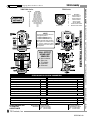
,QWURGXFWLRQ
Motor/Leadscrew-driven
1
9
10
16
20
30
32
33
34
47
52
54
TS Products, Inc.
LINEAR 1
3
Step counting
-$0.5K
1-100
2-100
-$1K
-$1K
-$0.5K
2.1-165 4.5-165
1.856
2200
2100
2000
1200
1100
1
Openloop3
With 12-volt motor armature
Shorter
3.9"-8.4"
Encoder
@ 60 ppr
Internal
Hall-effect
Switches
250 mA
max
Shortest
3.5"-7.7"
¼"-4"
Yes
Push/Pull
Adaptor
Option
No
½"-4"
6.3"-14.8"
Closedloop
STEPPING MOTOR
Yes
Push/Pull
Adaptor
Option
2
Pseudo-resolution compared to closed-loop
46 m-17mm
14 m5.1µm
11 m4.1µm
56 m-21mm
AM1524
.45-56
36 m27 m-17mm
23mm
56 m3.5µm
No
1616 6.3"-14.8" ½"-4" std
Motor
Closed- Conditions 145 mA Sealed 6" custom
loop
1624
and
Encoder
Encoder 500 mA Shorter
@ 60 ppr
1717 3.9"-18.2" ¼"-12" std
Timing
16", 18"
600 mA
Motor
Shortest
Opencustom
1724
loop
Conditions 750 mA 2.6"-15.4"
1000
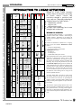
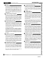
Housed in a tube, Linear Actuators
produce linear movement by converting
an electric motor’s rotation into
translation through a precision leadscrew and nut. Competing technologies
similarly housed in a tube include )
! Pneumatic cylinder,
! Voice coil,
! Piezoelectric stack.
As usual, each technology has its own
strengths and weaknesses.
0(&+$1,&$/29(59,(:
45 m2.8µm2
Servo
.36-56
Stall
7µm100
11mm
Servo
Servo
Servo
.631.7-165 3.6-165
56
Stall
Stall
Stall
300
300
100
-$1K
-$1K
Motor/Leadscrew-driven
38 m29 m-18mm
24mm
1717
1624
1624 1717 1724
1616
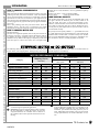
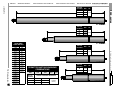
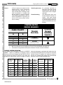
IRONLESS-CORE DC MOTOR
Limit
Sensing
Series
Control
Method
Electronic
Current
@ Stall1
Housing
Length
Travel
Thruster
Resolution
Rotating?
Maximum Velocity Range
units/sec
1616
Maximum Thrust
lbs
1724
Price
Mechanical
COMPARATIVE FEATURES
LINEAR ACTUATORS ROTARY ACTUATORS OPEN-LOOP CONTROLLERS CLOSED-LOOP CONTROLLERS CUSTOM SYSTEMS PRICING
@ ½"
Travel
,QWURGXFWLRQ
To produce the linear movement, a -.2" OD Thruster
protrudes on-axis from a nominal 1" OD housing in
standard actuators. Depending on the model, the
Thruster may be rotating or non-rotating and push up
to 300 lbs.
Ironless-core brushed DC, brushless DC, or stepping
motors power the actuators. Brushed DC motors
feature )
! Precious metal brushes,
! 3-28 vdc ironless-core armature.
Stepping motors feature )
! 2-phases,
! 24-steps/rev,
! Maximum 0.25A phase current.
These high-speed motors rotate a leadscrew through a
spur-gear or planetary-gear reducer. In the 1100,
1200, 2100, and 2200-series, the leadscrew itself is
the thruster and protrudes through a threaded Nose
Mounting. They can provide pull and also push with
the Push/Pull Adaptor [PPA] option. In contrast, the
1000 and 2000-series have push-only plungers independent from the rotating leadscrew. Hardened Push
Pads [PP#] and a protective Boot [B] for the leadscrew are available as options. In all versions, we lap
the leadscrew and its mating nut for a long life of
smooth, repeatable motions.
To mount, simply drill a 3/8" hole in a plate, insert
the actuator, and secure with the Nose Nut (see Page
49). The shorter travel devices are specifically-designed to replace typical micrometer spindles traditionally used in precise alignment of optics and translation slides.
The actuator’s compact package permits a user to nestle it into tight places without having to design a complete precision motion. For many practical applications, they are buried deep inside equipment to provide remote final alignment in difficult-to-reach locations.
TS Products, Inc.
LINEAR 2
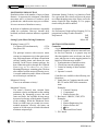
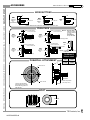
02725$/7(51$7,9(6
You can choose between the standard stepping, brushed ironlesscore DC, and semi-custom brushless DC motors to propel the Linear Actuators. Each motor type has its strengths and weaknesses. A
Selection Guide included in this section will help you make a
choice.
$1$/2*9(/2&,7<6(592
Although you can drive brushed DC-motor actuators from your own
electronics, we supply the SER3000 Analog Velocity Servo as well
as manual and µcomputer-based controllers. The servo expects a
low-current ±10 vdc velocity steering voltage from external sources
such as our 1000INT, 1000MOD, CONTROL2, or CONTROL3
controllers. In spite of load variations, the servo drives the motor at
a programmable constant velocity by sensing the motor's BEMF.
Additional circuitry senses unusual motor conditions ) moving too
slow and pushing too hard ) to indicate a limit-of-travel or stall conditions.
$48$'%(1&2'(5&/26('/223
Both 1000/1100 and 2000/2100-series have a built-in rotary encoder
directly coupled to the motor shaft. With 15PPR(Pulses per Revolution), it provides 60 counts in 4X decode. Because the motor drives
the leadscrew through a gearhead, the ratio directly multiplies the 60
counts. For example, a 262:1 ratio will produce 15,720 encoder
counts per revolution of the leadscrew. With a 32 TPI leadscrew,
these counts produce an incremental resolution of 2 µin. The 2phase outputs from an A-QUAD-B encoder are for direction and
position information. Its magnetic construction assures high immunity to induced EMI current at either TTL or CMOS levels.
/($'6&5(:3,7&+
Most actuators are available with either 32.3885 or 40 TPI leadscrews. The first pitch produces an exact resolution of 0.1 µm (a
common optical research standard) through the 262:1 gearhead if
using 2X encoder decode.
*($5+($'5$7,2
Since the comparatively small motors have extremely high rotary
velocity but low torque, we gear them down to perform useful work.
The 15/5 and 16/5 gearheads are available in 18 different ratios producing an incremental resolution from 50 m to 3µm at 4X encoder
decode. The 17/5 gearhead series has 14 different ratios to produce
incremental resolutions from 2 m to 4µm. Some gearheads are
available in a zero-backlash configuration that removes the 4 o clearance between drive gear teeth by preloading.
25'(5,1**8,'(
All Linear Actuators can be ordered with this number sequence )
Series)Travel)Motor Size)Gearhead Ratio)Leadscrew Pitch)Options
Example: 1000-05-1616-485-32-SD-V
ACTUATOR
SERIES
Brushed DC
[Sensing Motor Conditions for
Limit-of-Travel]
1000 ! Closed- loop
! Non-rotating
thruster
! Robust, enclosed
1100 ! Closed-loop
! Shorter housing
! Rotating thruster
1200 ! Open-loop
! Shortest housing
! Rotating thruster
Stepping
[Integral Hall-effect Limit-ofTravel Sensors]
2000 ! Closed- loop
! Non-rotating
thruster
! Robust, enclosed
2100 ! Closed-loop
! Shorter housing
! Rotating thruster
2200 ! Open-loop
! Shortest housing
! Rotating thruster
Brushless DC
30001 ! Semi-custom
1
Contact factory
TRAVEL
1000
-05
-1
-2
-4
-61
1100/1200
-025
-05
-1
-2
-4
-6
-8
-10
-12
$-141
2000
-05
-1
-2
-4
2100/2200
-025
-05
-1
-2
-4
MOTOR
SIZE
Brushed DC
-1616
-1624
-1717
-1724
Brushless DC
-35561
Stepping
-AM1524
GEARHEAD
RATIO
16/5-series for
brushed DC 1616
or 1624 motor
15/5-series for
AM1524 stepping
motor
-6.3
-1670
-11.8
-3101
-22
-5752
-41
-10683
-76
-19813
-141
-36796
-262
-68245
-485
-126741
-900
-235067
16/7-series for
brushed DC 1717
or 1724 motors
-3.71
-415
-14
-592
-43
-989
-66
-1526
-134
-2608
-159
-4356
-246
-5647
LEADSCREW
PITCH
OPTIONS
-32
32.3885 TPI for
actuators )
1000
1100
2000
2100
No dash designator for OPTIONS indicates STANDARD
CONFIGURATION with -NB1
Nose Button and axial discharge of control cable.
-40
40.0000 TPI for
actuators )
1100
1200
2100
2200
-NB# Nose Button
-NB1 Short radius [std]
-NB2 Long radius
-NB3 Flat
-B#
-B05
-B1
-B2
-PPA
Boot
½" travel
1" travel
2" travel
Push/Pull Adaptor
-PP# Push Pad
-PP1 Hemispherical, short-radius
-PP2 Conical, short-radius
-PP3 Hemispherical, long- radius
-PP4 Conical, long-radius
-PP5 Flat
-S#a Custom modification designator
-SD
-V
-ZB
Cable Side Discharge
[Axial Discharge is std]
Vacuum Compatibility
Zero Backlash Gearhead
-CN# Connector
-CN1 MiniDIN8P (1000, 1100,
1200, 2200)
-CN2 DA-15P (2000, 2100)
-CN3 Mono 2.5mm Phone Plug
(1200)
-CN4 Tinned 18" Leads
-CN5 Ribbon & Header
TS Products, Inc.
LINEAR 3
PRICING CUSTOM SYSTEMS CLOSED-LOOP CONTROLLERS OPEN-LOOP CONTROLLERS ROTARY ACTUATORS LINEAR ACTUATORS
,QWURGXFWLRQ
Motor/Leadscrew-driven
,QWURGXFWLRQ
Motor/Leadscrew-driven
LINEAR ACTUATORS ROTARY ACTUATORS OPEN-LOOP CONTROLLERS CLOSED-LOOP CONTROLLERS CUSTOM SYSTEMS PRICING
+2:72&+226($*($5+($'5$7,2
Closed-Loop
While examining the Motor/Gearhead Selection Tables, pick a ratio
producing less than your desired resolution. Check the maximum
velocity for that gearhead. You may have to compromise your initial
specifications to select the best actuator for your application. Because the motor has a fixed maximum power and encoder frequency,
you must juggle Velocity against Load Capacity against Resolution.
Open-Loop
Pick a ratio producing more than your desired thrust. Check the
maximum velocity. You may have to compromise your original
specifications to select the best fit for Velocity and Load Capacity.
+2:72&+226($027256,=(
consider the 1717 and 1724 motors ) the 16/7 gearhead can push up
to 300 lbs.
Brushless DC-Motor ) Only one model available.
) Only one model available.
Stepping Motor
/2$'&$55<,1*&$3$&,7<
The specified Load Limit is to protect the individual teeth on the
spur gears. Because the leadscrew pitch is fixed (32.3885 or 40
TPI), the output drive gears see the load independent of ratio.
Therefore, we limit the motor current in the Servo and thus the actuator’s ability to push more than 100 or 300 lbs. Without the Servo,
you may elect to push higher loads but you will sacrifice some of
our mechanical warranty.
Brushed DC-Motor
If Load is not a significant problem, there is only one reason for selecting the 1616 motor ) increased Velocity. Because the 1624 motor produces 4X torque compared to the 1616, it has 30% lower
maximum velocity. When Load Capacity is important, pick the 1624
motor but expect it to move more slowly. For even higher loads,
We specify two load capacity numbers ) 1. @ maximum servo and
2. @ stall (limit-of-travel). The maximum servo value represents the
maximum load to remain inside a constant velocity servo window
such as with our SER3000 Analog Velocity Servo. Outside this window, the motor’s velocity is inversely dependent on the load.
The following table will help you choose between brushed, brushless DC motor, and a stepping motor. Although many facts are pre-
sented, often people choose one motor style over another because of
personal experience or familiarity.
MOTOR PERFORMANCE COMPARISON
DC (Ironless-core)
Stepping (Bipolar)
Category
Brushless
2000-family
1
Brushed
Semi-Custom
1000-family
Open-Loop2 Closed-Loop3 Open-loop Closed-Loop Open-Loop Closed-Loop
ELECTRONIC
Digital Coordinate Control
Run-away possible?
4
Attitude of being In Control?
5
Resume Running after Stall?
Sensitive to acceleration?
6
7
Single-Polarity Power Supply?
Complex Drive Electronics? 9
8
YES
Yes
No
Yes
No
Yes
No
No
Unlikely
Unlikely
Yes
Yes
Yes
Yes
No
No
No
No
No
No
Yes
Yes
Yes
Yes
Yes
Yes
No
No
No
No
Yes
Yes
Yes
Yes
No
No
Yes
Yes
Some
Some
No
No
Yes
Yes
Some
Some
No
No
Yes
Yes
No
No
No
No
Yes
Yes
No
No
No
No
No
No
No
No
Yes
Yes
Yes
Yes
Yes
Yes
No
No
Yes
Yes
No
No
No
No
MECHANICAL
Acoustic Noise? 10
Excessive Vibration?
Motor runs hot?
11
12
Brushes to wear-out?
High inertia?
13
14
Inaccuracy under load?
15
Brushless DC-motors are only available in semi-custom
2" OD housings for high-thrust applications.
Open-Loop control of a stepping motor requires counting
the step commands to control the position. If you loose
step-synchronization, the controller will be unaware of
this condition unless some expected external event is also
missing.
Closed-Loop control of a stepping motor means that an
A-QUAD-B position encoding device is somewhere in the
motion subsystem. Although you issue individual step
commands, you determine the final position by the encoder, independent of the number of steps. Even with loss
of step synchronization, the encoder information is accurate.
TS Products, Inc.
LINEAR 4
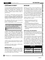
Run-away?
In contrast to easily-controlled brushed DC motors,
stepping motors and brushless DC-motors require complex switching of current flow through the motor windings. Therefore, failure in a servo, amplifier, or powersupply can falsely move the brushed DC motor ) causing the motor to run-away! While the DC motor’s tendency is to move, the stepping motor’s tendency is to
not move. Although a simple battery will move a brushed DC motor, only complex electronics will move a
stepping motor.
Attitude of Being IN CONTROL?
Each step is the result of a deliberate electronic event.
In contrast, the brushed DC motor only needs a voltage
source to run. In a closed-loop environment, instead of
thinking GO TO HERE, you ask a DC motor, WHERE
ARE YOU? In DC controllers, the encoder counts maintain either a hardware or software position counter.
Stepping controllers issue timed pulses to a driver that
produces the complex switching to move the motor.
Resume Running after Stall?
A stepping motor can lose step-synchronism easily if
the load increases beyond the operating window for the
current velocity or acceleration. If the time is long
enough, the motor will stall until the motion sequence
starts again. Even if it is operating with an encoder in
closed-loop fashion, the motor will stall. The controller
must handle this error condition and restart the motion
toward the final coordinate.
In comparison, the DC motor ) brushless or brushed )
will continue to try to move in the face of adversity.
Although it may slow down, it will resume running normally after removing the offending load. However, in a
closed-loop environment with digital velocity servoing,
the controller may sense a following error and terminate
the motion.
Sensitive to Acceleration?
Stepping motors will lose step-synchronization if accelerated or decelerated too fast. Taking the next step too
early or too late causes this error and results in loss of
step synchronism ) it may even run backwards! If the
load varies, it is difficult to exactly find the correct acceleration to guaranty faultless stepping. One common
approach is to accelerate much more slowly to assure
not losing synchronism. Although you don’t lose position when the motor stalls in closed-loop environment,
it is inconvenient to restart the motion.
Single-Polarity Power Supply?
We use balanced-bridge analog velocity servos with our
DC motors to achieve a smooth, quick-response movement. In contrast, some pulse-width modulated (PWM)
servos may create audio noise, mechanical vibration,
and cogging at low velocities. The balanced-bridge
servo by necessity has a bipolar power source (±15vdc).
On the other hand, both the brushed DC-motor and
stepping motor operate from unipolar supplies.
,QWURGXFWLRQ
Complex Drive Electronics?
Although brushed DC motors can run from a battery,
brushless DC and stepping motors require more elaborate electronic controllers. Eventually, both motors often have complex controllers due to all the collateral
events they are controlling ) limit handling and encoder
decoding.
Acoustic Noise?
Excessive Vibration?
The stepper's action is violent ) especially for full steps
) the magnitude of the switched electrical current is
independent of motor velocity! This jolt produces both
audio noise and mechanical vibration that is especially
noticeable at lower velocities. However, the DC
brushed and brushless motors feature seamless transitions from winding to winding. Except for vibration
from bearings and air currents, these motors are noise
and vibration free!
Fortunately, microstepping reduces the current differential being switched and the acoustic noise. Due to the
motor's construction, we recommend limiting microstepping to 4X ) unfortunately, this is still not sufficient
to completely illuminate noise and vibration.
Motor runs hot?
A stepping motor is often fully-powered all the time to
retain its maximum holding torque. If the system friction is high enough, holding current can be substantially
lowered. For example, we recommend reducing the
current to 100mA from a running 250mA when stopped. In either case, this continuous current makes the
stepping motor hotter than equivalent DC motors. Because the motor gets hot, the linear actuators should be
in contact with a heat conducting element such as a
thick metal plate. Without adequate heat conduction, it
is possible to overheat and destroy the motor windings.
Brushes to wear-out?
Obviously, stepping and brushless DC motors do not
have brushes to wear out ) this is one of their primary
strengths. In contrast, even the precious metal brushes
of normal DC motors eventually wear out. The only
question is: how long do they last? While the motor
manufacturer conservatively specifies the brushes for
1000 hours at maximum conditions, we anticipate
2000-5000 hours. In stepping and brushless DC motors,
the bearings should last for 50,000 hours.
High inertia?
Since they have no moving magnets, only brushed,
ironless-core DC motors can exhibit ultra-low rotor
inertia. In contrast, both the stepping and brushless DC
motors have moving permanent magnets. This increased mass invariably results in slower starts and
stops when compared to ironless-core DC motors with
identical magnetic materials. However, the effects of
higher inertia are effectively negated by high-strength
samarium-cobalt rotor magnets in the stepping motor.
TS Products, Inc.
LINEAR 5
PRICING CUSTOM SYSTEMS CLOSED-LOOP CONTROLLERS OPEN-LOOP CONTROLLERS ROTARY ACTUATORS LINEAR ACTUATORS
Motor/Leadscrew-driven
,QWURGXFWLRQ
Motor/Leadscrew-driven
LINEAR ACTUATORS ROTARY ACTUATORS OPEN-LOOP CONTROLLERS CLOSED-LOOP CONTROLLERS CUSTOM SYSTEMS PRICING
Inaccuracy under load?
In unloaded condition, stepping motor's accuracy is ±3%
of full step or ±27 arc minutes. Under load, accuracy is
further decreased an arc minute for every load change
equivalent to 1% of the motor's rated torque. Since the
stepper holds position by balanced magnetic fields ) addi-
tional force always causes position distortion. In contrast,
the closed-loop DC motor has no errors introduced by
loading variations. However, the accuracy of both motors
is equivalent in a closed-loop environment.
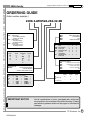
SELECTION GUIDE
COMPARATIVE FEATURES
Stepping
1. Long life due to absence of brushes;
2. Vibrates and noisy in full or half-step operation )
4X maximum microstep recommended;
3. Direct open-loop control ) Move another step;
4. Less-expensive position control;
5. Larger size required to assure accurate openloop performance;
6. Higher inertia from rotating permanent magnets
results in slower Start and Stop performance;
7. Numerous, but complex low-cost controllers
available;
8. Possible loss of step-synchronism causing Stall;
9. Runs hot, even at rest;
10. Unipolar power supply;
11. No EMI from arcing nor particulate contamination
from brushes;
12. Open-loop microstep inaccuracy under varying
loads;
13. Thinks digital.
Brushed DC
1. Gold and silver brush/commutator give 20005000 hours lifetime;
2. Ultra-smooth and quiet in all modes of operation;
3. Indirect control ) Where are you?;
4. Position control requires encoder/resolver;
5. Smaller size since it never looses stepsynchronization;
6. Low inertia from ironless-core results in
rapid Start and Stop performance;
7. Fewer, but simple higher-cost controllers;
8. In closed-loop environment, always tries to move
without loss of information;
9. No electrical power consumption at rest;
10. Bipolar power supply;
11. Minimal arcing and zero contamination due
to arc suppression and fine metal brushes;
12. Accuracy independent of load;
13. Thinks analog.
RECOMMENDATIONS
Condition
1. Equipment sensitive to vibration ) optics,
interferometry, pattern generation.
2. Long life at maximum conditions.
3. Vacuum environment.
4. Ultra-fast starting and stopping response.
5. Zero EMI.
6. Low thermal emissions.
7. Interface to standard board level controllers
for table-top PCs.
8. Low electrical power consumption.
9. Low acoustical noise.
10. Open-loop position control.
11. Run-away protection from secondary component failure.
12. High accuracy under load.
13. Repeatable HOME sensor. 2
1
BLDC1
3000-series
T
Brushed DC
1000-family
T
Stepping
2000-family
)
T
T
T
)
T
)
T
)
T
T
T
T
)
)
T
T
T
T
T
)
)
T
)
)
)
)
T
T
)
T
)
)
)
T
T
T
Brushless DC-motor only available in semi-custom, high-thrust, 2" OD Linear Actuator version.
2
Check availability of built-in Hall-effect Limit-of-Travel sensors for 1000-family.
TS Products, Inc.
LINEAR 6
/($'6&5(:$&&85$&<
%$&./$6+
A Linear Actuator's absolute accuracy is first
a function of the leadscrew’s pitch accuracy. Even
though the gearhead/encoder combination may
produce a large number of counts per leadscrew
revolution, absolute position directly relates to
pitch accuracy.
Backlash is present in most all mechanical systems, although it might be too small to be perceived. We define backlash as the absence of physical movement when the direction is first reversed. Clearances between moving internal parts
cause the backlash but also permit smooth operation. There is no resultant motion until all the tolerances in the mechanical system have been taken
out and the force is again applied to the output.
The leadscrew is fabricated by single-point cutting
on a CNC lathe in a temperature regulated environment. It is lapped to produce a fine surface and
mated to its Nose Mounting or Nut. However, this
lapping does little to compensate for pitch errors.
We calibrate the lathe with a laser and control its
leadscrew through a look-up table.
Because of the prohibitive cost of a more accurate
Error analysis by laser interferometer
shows that our leadscrews have
maximum peak-to-peak pitch errors
ranging from ±0.5 µm to ±5 µm over 4"
travel.
leadscrew, one method for improving absolute
accuracy is to use a computer look-up table. With
a look-up table, you must have a repeatable starting point ) a HOME point. Fortunately, the 2000family has built-in Hall-effect sensors for both the
Forward and Reverse limit. You can use either
sensor as the HOME sensor, repeatable to at least
10 µin (0.25 µm).
Another accuracy improvement method is a collateral A-QUAD-B external linear encoder such as a
glass scale.
TS Products will supply leadscrew calibration by
laser interferometer as an option.
RESOLUTION
Resolution is the smallest incremental distance
represented by one step or encoder count. Resolution does not relate to absolute accuracy. However, during leadscrew calibration, the resolution
governs the sample interval of the data.
Common methods to remove or reduce backlash
when using Linear Actuators )
1. Relatively-high unidirectional load
! Spring-return of translation stages
! Gravity
2. Zero-backlash gearheads (-ZB Option)
3. Motion-control programming that always approaches the final coordinate in the same direction.
4. Motion-control programming that compensates
for known backlash every time there's a switch
in direction.
ZERO-BACKLASH GEARHEAD
80% of backlash in the in-line linear actuators is
caused by the clearance of the teeth in the 15/5 and
16/5 gearhead's output drive gear. The -ZB option
removes this major contributor.
The Zero Backlash Gearhead contains two parallel
stacks of spur gears in one package with a common attachment to both the output and motor
drive gear. Prior to joining with the motor, one
gear stack is advanced until all the tooth clearance
at the output gear is consumed. Now, it is joined
to the motor's drive gear and the gearhead-generated backlash is canceled. This preloading increases friction and diminishes lifetime slightly.
%$&./$6+
Gearhead Style
Normal
10 µm ± 1 µm
Zero-Backlash
2 µm ± 1 µm
TS Products, Inc.
LINEAR 7
PRICING CUSTOM SYSTEMS CLOSED-LOOP CONTROLLERS OPEN-LOOP CONTROLLERS ROTARY ACTUATORS LINEAR ACTUATORS
,QWURGXFWLRQ
Motor/Leadscrew-driven
,QWURGXFWLRQ
Motor/Leadscrew-driven
LINEAR ACTUATORS ROTARY ACTUATORS OPEN-LOOP CONTROLLERS CLOSED-LOOP CONTROLLERS CUSTOM SYSTEMS PRICING
BACKLASH CONSTANT?
While backlash is never a constant because of eccentricities in the individual gears as well as irregularities in guidance slots, the following table is
the expected nominal backlash. The best method
for determining maximum backlash is to perform
a physical experiment.
BACKLASH RESPONSE KNEE
At the relatively fine dimensions of linear actuators with high gear ratios, the knee of the response
curve is not sharp. As the backlash begins to be
picked-up, the physical movement for each resolution element is less than expected. Eventually, the
movement matches the resolution and the actuator
responds linearly again.
(;3(&7('%$&./$6+
1100-series (60-count Encoder)
GEARHEAD
RATIO
Distance
per
Count
EQUIVALENT
COUNTS
Normal
ZeroBacklash
2200-series (24 full-steps/rev)
Distance
per
Step
EQUIVALENT
STEPS
Normal
ZeroBacklash
6.3:1
2.0 µm
5
1
4.1 µm
2
0
11.8:1
?
262:1
?
3101:11
1.1 µm
?
0.05
?
4.1 m
9
?
200
?
2439
2
?
40
?
488
2.2 µm
?
76 m
?
8.4 m
5
?
132
?
1193
1
?
26
?
239
1
Zero-backlash Gearhead Option is only available up through the 3101:1 gear ratio.
6,'(/2$'
Sideload on the extended Thruster will increase
internal friction and reduce available thrust dramatically. When rotating a tangent arm with a linear actuator, sideload becomes a significant factor
influencing the thrusting force. As a rule of thumb,
limit the sideload to a maximum of 5 lbs.
TS Products, Inc.
LINEAR 8
VHULHV
DC-Motor/Leadscrew-driven
LINEAR ACTUATORS ROTARY ACTUATORS
IDPLO\
1000-series . . . . .
1100-series . . . . .
1200-series . . . . .
10
16
20
1000-series Linear Actuators
OPEN-LOOP CONTROLLERS
These high-quality actuators directly replace
micrometer heads in micro-motion applications
with a typical resolution of 0.05µm. With built-in
magnetic A-QUAD-B position encoder for
closed-loop positing applications, the 1000-series
are available in 32 resolution/velocity variations,
4 travels, and 3 load categories. Its principal
feature is a non-rotating thruster that pushes
against an external return force.
ged enough to withstand an accidental drop on the
floor. Quiet and sealed from external moisture
and dust contamination, the 1000-series can
perform directly exposed to harsh weather.
CLOSED-LOOP CONTROLLERS
Formed in a 1"OD housing, this actuator is rug-
The 1000-series can be operated from either your
controller/servo or from our SER3000-series of
Analog Velocity Servos. In its normal configuration, the 18" cable from this actuator is terminated
in a MiniDIN8P connector. For vacuum environment, all lubricants are space-qualified.
Major Features
Typical Customizing
!
!
!
!
!
!
!
!
!
!
!
!
!
Non-rotating thruster
Built-in position encoder
Travels of ½", 1", 2", 4"
Thrusts up to 300 lbs.
Maximum velocity up to 18 mm/sec
Resolutions down to 2.2 in (56 m)
Expected minimum absolute accuracy =
2 µm/in
! Internal limit-of-travel/torque sensing
through Analog Velocity Servo
! Vacuum-compatibility option
! Axial or side cable discharge
Thruster length variation
Omit position encoder
Cable length variation
Increased thrust capacity
Adjustable thrust limit
Leadscrew error calibration
CUSTOM SYSTEMS
PRICING
TS Products, Inc.
LINEAR 10
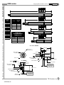
VHULHV
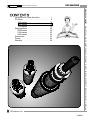
ENCODER
GEARHEAD
HUB
DOG-POINT
SET SCREWS
DRIVESHAFT
BEARINGS
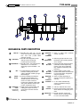
! MicroMo 1616, 1624, 1717, or 1724 motor with armature voltage ranging from 324 volts (17,000 RPM maximum velocity).
! MicroMo HE15 Magnetic Encoder with
60 counts at 4X decode provides position
information.
! MicroMo 16/5 or 16/7 Gearhead with ratios from 3.71:1 to 235,067:1 depending
on space available ) see charts.
! Attached to gearhead to prevent rotation.
! Prevents HUB from rotating.
! Stationary, precision-ground stainlesssteel with 32.3885 TPI pitch converts
rotary motion into linear movement of
Drive Nut. Bonded to gearhead output
shaft with Loctite adhesive rated at -65oF
to 300oF temperature range.
! Precision stainless-steel bearings promote exceptionally-smooth motion.
! Locks bearings into position.
BEARING
SPACERS
! Supports bearing outer race.
OUTER RACE
NUT
INNER RACE
NUT
BEARING SEAT
! Supports bearing inner race.
DOG-POINT
SET SCREWS
REVERSE
STOP
CUSHION
PUSH ROD
FORWARD
STOP
FORWARD
STOP
CUSHION
NOSE
BEARING
MOUNTING
NUT
HOUSING
COUPLER
MOTOR
HOUSING
END CAP
! Phosphor-bronze nut moves linearly as
Driveshaft rotates to produce motion.
! Rides in mating slot in Drivenut to prevent rotation during linear motion.
! Rubber O-ring provides soft stop for
Drivenut at Reverse End-of-Travel.
! Non-rotating stainless-steel rod provides
linear thrust to object being pushed )
polished; hardened by heat-treatment;
0.1875 spherical dia tip.
! Force-fit onto Push Rod, provides Forward Limit-of-Travel.
! Elastomer
cushion
provides
soft
FORWARD Limit-of-Travel.
! Precision cylinder bearing is force-fit to
Housing. Lapped to Push Rod for smooth, low-jitter, thrusting movement.
! 0.55" OD secures actuator to mounting
plate. ID 3/8-40 UNC.
! <1" OD, black anodized tube. Vacuumcompatible Housing is unanodized.
! Joins Motor Housing to Housing.
! Covers Motor/Gearhead/Encoder.
! Closes Motor Housing and provides
strain-relief for cable.
! 1/8" OD cable with 7 conductors.
ACTUATOR
CABLE
PRICING
! Contacts outer bearing race and supports Reverse Stop Cushion.
DRIVENUT
CLOSED-LOOP CONTROLLERS
MOTOR
CUSTOM SYSTEMS
MECHANICAL PARTS DESCRIPTION
OPEN-LOOP CONTROLLERS ROTARY ACTUATORS
LINEAR ACTUATORS
DC-Motor/Leadscrew-driven
TS Products, Inc.
LINEAR 11
LINEAR ACTUATORS ROTARY ACTUATORS
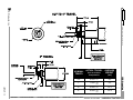
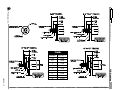
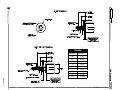
DIM
#1
14.303
#2
14.553 ±.020
#3
14.803
TOL
VHULHV
OPEN-LOOP CONTROLLERS
CLOSED-LOOP CONTROLLERS
CUSTOM SYSTEMS
PRICING
LINEAR 12
MOTOR
HOUSING
75$9(/
17/5
DIM
#1
10.303
#2
10.553 ±.020
#3
10.803
MOTOR
HOUSING
DIM
3.71:1
#1
7.303
14:1
#2
7.553
22:1
43:1
#3
7.803
41:1
159:1
76:1
246:1
141:1
415:1
262:1
592:1
TS Products, Inc.
989:1
900:1
1,526:1
1,670:1
2,608:1
3,101:1
4,365:1
5,752:1
10,683:1
19,813:1
5,647:1
TOL
±.020
75$9(/
PERMITTED MOTOR/GEARHEAD
COMBINATIONS
MOTOR
SIZE
1616
1624
36,796:1
MOTOR
HOUSING
68,2451
#1
485:1
11.8:1
126,741:1
#2
19,813:1
141:1
235,067:1
#3
235,067:1
5,752:1
1717
1724
MOTOR
HOUSING
DIM
#1
6.303
#2
6.553
#3
6.803
TOL
±.020
HIGHEST POSSIBLE GEAR RATIO
Contact
Factory
75$9(/
DC-Motor/Leadscrew-driven
6.3:1
11.8:1
485:1
TOL
75$9(/
AVAILABLE
GEAR RATIOS
16/5
MOTOR
HOUSING
DC-Motor/Leadscrew-driven
TS Products, Inc.
CUSTOM SYSTEMS
CLOSED-LOOP CONTROLLERS
ACTUAL TRAVEL
Prior to Cushion
Compression
AVERAGE
WEIGHT
(oz.)
0.5"
0.569 -+.022
.027
8.2
1"
1.069 -+.022
.027
9.2
2"
2.069 -+.022
.027
12.1
4"
4.069 -+.022
.027
22.4
OPEN-LOOP CONTROLLERS ROTARY ACTUATORS
LINEAR ACTUATORS
VHULHV
LINEAR 13
PRICING
NOMINAL
TRAVEL
VHULHV
DC-Motor/Leadscrew-driven
LINEAR ACTUATORS ROTARY ACTUATORS
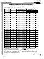
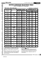
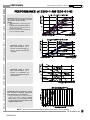
02725*($5+($'6(/(&7,217$%/(
RU0RWRUV*HDUKHDGVZLWK;(QFRGHU0XOWLSOLHU
6HULHV/LQHDU$FWXDWRU
RESOLUTION1
1616
Motor
1624
Motor
6.3
2.04 µm
80.4 µin
1.10
43.4
593 m
23.4 µin
320
12.6
172
6.78
92.9
3.66
50.0
1.97
27.0
1.06
14.5 m
571 in
7.83
308
4.21
166
2.27
89.5
1.22
48.2
660 m
26.0 in
355
14.0
192
7.54
103
4.06
55.6
2.19
.69-14 mm
27-550 mils
.37-7.5
15-290
.20-4.0
7.9-160
.11-2.2
4.3-86
.059-1.2
2.3-46
32-630 µm
1.2-25 mils
17-340
.67-13
9.2-180
.36-7.2
4.9-99
.19-3.9
2.7-53
.10-2.1
1.4-29
.056-1.1
.77-15 µm
30-610 µin
.42-8.3
16-330
.22-4.5
8.8-180
.12-2.4
4.8-95
.065-1.3
2.6-51
35-700 m
1.4-28 µin
19-380
.74-15
.53-11 mm
21-420 mils
.29-5.7
11-230
.15-3.1
6.1-120
.08-1.7
3.3-65
45-900
1.8-35
24-480 µm
.95-19 mils
13-260
.51-10
7.0-140
.28-5.5
3.8-75
.15-3.0
2.0-41
.080-1.6
1.1-22 µm
43-860 µin
.59-12
23-470
.32-6.4
13-250
.17-3.4
6.7-140
.092-1.8
3.6-73
.050-1.0
2.0-39
27-540 m
1.0-21 µin
15-290
.57-11
11.8
[11.86420]
22
[22.03351]
41
[40.86557]
OPEN-LOOP CONTROLLERS
76
[75.89319]
141
[140.75917]
262
[261.40989]
485
[484.83713]
900
[900.41181]
1670
CLOSED-LOOP CONTROLLERS
[1669.99451]
3101
[3101.41837]
5752
[5752.20313]
10683
[10682.66295]
19813
[19813.14453]
36796
[36795.83984]
68245
CUSTOM SYSTEMS
[68245.27344]
126741
[126741.22210]
235067
[235067.04688]
2
3
VELOCITY2 units/sec
GEARHEAD
RATIO
[6.39683]
1
/HDGVFUHZ
PRICING
At 60 A-QUAD-B encoder counts per revolution.
Typical 20:1 velocity range for continuous-style motion.
@ max velocity (50% No-Load Velocity). Typical variation of maximum load for 1000-series is ±30%.
1100-Series is ±35%. Suggested minimum load is 7
lbs or 50% of maximum for optimal operation.
4
5
6
73,
MAXIMUM LOAD3 (lbs)
1616 Motor
1624 Motor
4
5
Servo
Stall
Servo4 Stall5
.56
.97
2.2
3.9
.25kgm
.44kgm
1.kgm
1.8kgm
1.0
1.8
4.2
7.2
.45kgm
.82kgm
1.9kgm
3.3kgm
1.7
3.0
7.0
12
.77kgm
1.4kgm
3.2kgm
5.5kgm
3.2
5.6
13
22
1.5kgm
2.5kgm
5.9kgm
10kgm
5.4
9.4
22
38
2.4kgm
4.3kgm
10kgm
17kgm
10
17
40
70
4.5kgm
7.7kgm
18kgm
32kgm
17
29
566
1006
7.7kgm
13kgm
[67]
[120]
31
54
56
100
14kgm
24kgm
26kgm
45kgm
56
100
56
100
56
100
52
90
24kgm
41kgm
566
1006
[96]
[170]
56
100
26kgm
45kgm
56
100
56
100
56
100
56
100
56
100
56
100
56
100
56
100
56
100
56
100
56
100
56
100
56
100
56
100
While still inside a typical velocity servo window.
@ velocity = 0 (STALL).
Maximum thrust at STALL limited to 100 lbs to protect gearhead from damage. Maximum thrust at
maximum velocity still within Servo Window is 56%
of STALL thrust. Limitation by motor current reduction.
TS Products, Inc.
LINEAR 14
/HDGVFUHZ
2
GEARHEAD
RATIO
RESOLUTION1
1717
Motor
1724
Motor
3.71
3.52 µm
139 µin
947 m
37.3 µin
305
12.0
197
7.77
97.9
3.85
82.0
3.23
53.1
2.09
31.5
1.24
22.1 m
869 in
13.2
520
8.57
337
5.01
197
2.99
118
2.31
91.1
.92-18 mm
36-720 mils
.25-4.9
9.7-194
.079-1.6
3.1-62
.051-1.0
2.0-40
25-510 µm
1.0-20 mils
21-430
.84-17
14-280
.54-11
8.2-160
.32-6.4
5.7-110
.23-4.5
3.4-69
.14-2.7
2.2-45
.087-1.8
1.3-26
.051-1.0
.78-16 µm
31-610 µin
.60-12
24-470
.56-11 mm
22-440 mils
.15-3.0
6.0-120
48-970 µm
1.9-38 mils
32-630
1.2-25
16-310
.62-12
13-260
.52-10
8.5-170
.33-6.7
5.0-100
.20-4.0
3.5-71
.14-2.8
2.1-42
.83-1.7
1.4-27
.51-1.1
.80-16 µm
32-630 µin
.48-9.6
19-380
.37-7.4
15-290
[]
14
[13.7959]
43
[42.9206]
66
[66.2204]
134
[133.5309]
159
[159.4195]
246
[245.9615]
415
[415.4294]
592
[592.1296]
989
[988.8914]
1526
[1525.7182]
2608
[]
4365
[]
5647
[]
1
2
At 60 A-QUAD-B encoder counts per revolution.
Typical 20:1 velocity range for continuous-style motion.
@ max velocity (50% No-Load Velocity). Typical variation of maximum load for 1000-series is ±30%.
1100-Series is ±35%. Suggested minimum load is 7
lbs or 50% of maximum for optimal operation.
4
5
6
MAXIMUM LOAD3 (lbs)
1716 Motor
1724 Motor
Servo4 Stall5 Servo4 Stall5
1.7
2.9
3.6
6.2
.77kgm
1.3kgm
1.6kgm
2.8kgm
5.6
9.7
12
21
2.5kgm
4.4gm
5.4kgm
9.5kgm
15
26
32
56
6.8kgm
12kgm
15kgm
25kgm
23
41
50
87
10kgm
19kgm
23kgm
39kgm
41
70
86
150
19kgm
32kgm
39kgm
68kgm
48
84
100
180
22kgm
38kgm
45kgm
82kgm
75
130
160
280
34kgm
59kgm
73kgm
130kgm
120
200
1656
3006
54kgm
91kgm
[250]
[430]
160
290
165
300
73kgm
130kgm
73kgm
140kgm
1656
3006
[280]
[480]
165
300
165
300
165
300
75kgm
140kgm
165
300
165
300
165
300
165
300
165
300
165
300
While still inside a typical velocity servo window.
@ velocity = 0 (STALL).
Maximum thrust limited to 300 lbs to protect
gearhead teeth from damage. Maximum thrust at
maximum velocity still with Servo Window is 56% of
STALL thrust. Limitation by motor current reduction.
PRICING
3
VELOCITY units/sec
73,
OPEN-LOOP CONTROLLERS ROTARY ACTUATORS
6HULHV/LQHDU$FWXDWRU
CLOSED-LOOP CONTROLLERS
NOTE Contact factory for limitations on particular combinations of motor, gearhead ratio, and travel.
CUSTOM SYSTEMS
02725*($5+($'6(/(&7,217$%/(
RU0RWRUV*HDUKHDGVZLWK;(QFRGHU0XOWLSOLHU
LINEAR ACTUATORS
VHULHV
DC-Motor/Leadscrew-driven
TS Products, Inc.
LINEAR 15
VHULHV
LINEAR ACTUATORS ROTARY ACTUATORS
OPEN-LOOP CONTROLLERS
Although these actuators have a built-in AQUAD-B position encoder for closed-loop
operation, they are much shorter than the 1000series because the rotating leadscrew is also the
thruster. A typical length reduction is 2.28" for
the 0.5" travel. Two guiding slots on opposite
sides of the housing prevent the motor from
rotating as the leadscrew is rotated. Marked keys
in these slots also serve as a coarse indicator of
position.
A shaped and polished Nose Button provides a
precise contact point as well as a Reverse
mechanical stop. The Forward mechanical stop is
provided by an elastomer cushion inside the
housing connected directly to the leadscrew. The
0DMRU)HDWXUHV
CLOSED-LOOP CONTROLLERS
CUSTOM SYSTEMS
! Short housing length
! Built-in position encoder
! Travels of ¼", ½", 1", 2", 4", 6", 8", 10",
12" [Custom = 16", 18"]
! Thrusts up to 300 lbs.
! Maximum velocity up to 18 mm/sec
! Resolutions down to 2.2 in (56 m)
! Expected minimum absolute accuracy =
2 µm/in
! Internal limit-of-travel/torque sensing
through optional SER3000 Analog
Velocity Servo
! Vacuum-compatibility option
! Axial or side cable discharge
DC-Motor/Leadscrew-driven
keys in the guiding slots do not provide any endsof-travel. In this way, the severe mechanical
forces from running into the ends-of-travel are
prevented from reaching the gearhead and motor.
For pulling applications, a [-PPA] Push/Pull
Adaptor option replaces the Nose Button.
The 1100-series can be operated from either your
controller/servo or from our SER3000-series of
Analog Velocity Servos. In its normal
configuration, the 18" cable from this actuator is
terminated in a MiniDIN8P connector. For
vacuum environment, all lubricants are space-qualified.
7\SLFDO&XVWRPL]LQJ
!
!
!
!
!
!
!
!
!
Shorter housing
Non-standard travels, such as 0.6"
Thruster length variation
Omit position encoder
Cable length variation
Increased thrust capacity
Adjustable thrust limit
Leadscrew error calibration
Custom Nose Button
PRICING
TS Products, Inc.
LINEAR 16
VHULHV
GEARHEAD
KEY
DRIVE
SHAFT
FORWARD
STOP
[Stop Shaft
Extension]
! Double-tabbed key holds the gearhead from rotating and prevents
choking sideloads created by singletabbed designs.
! Precision-rolled/ground stainlesssteel with either 32.3885 TPI or
40.0000 TPI pitch converts rotary
motion into linear movement )
bonded onto gearhead output shaft
with Loctite adhesive rated at -65 oF
to 300oF temperature range.
! Rigidly fixed on the Driveshaft, this
rotating piece stops all forward
motion when it touches the Nose
Mounting.
. . . FORWARD
STOP
CUSHION
! Teflon or rubber donut produces
smooth, soft stops.
NOSE
MOUNTING
! Stationary phosphor-bronze nut for
Driveshaft. Outer mounting threads
are d-40 UNC.
! Rotating stainless-steel hemisphere
(.200" Dia) contacts object being
pushed ) also acts as a Reverse
stop. Polished; hardened by heattreatment.)
! Assures metal-to-metal contact
between Nose Button and Driveshaft
to insure Nose Button straightness
and good dynamics.
! Teflon or rubber (depending on
Actuator velocity) donut produces a
soft stop.
NOSE
BUTTON
NOSE
BUTTON
WASHER
REVERSE
STOP
CUSHION
HOUSING
CABLE
ENDCAP
MOUNTING
NUT
! <1" O.D. black anodized body.
Vacuum compatible housing is
unanodized.
! 1/8" O.D. cable-coil with 7 wires.
! Closes-up the actuator and provides
strain-relief for the cable going to the
servo.
! Nut with 0.55"O.D. secures the
actuator onto its mounting surface.
I.D. has d-40" UNC threads.
TS Products, Inc.
LINEAR 17
CLOSED-LOOP CONTROLLERS
ENCODER
! MicroMo 1616, 1624, 1717, or 1724
motor with armature voltage ranging
from 3-24 volts (17,000 RPM
maximum velocity).
! MicroMo HE15 Magnetic Encoder
with 60 counts at 4X decode
provides position information.
! MicroMo 16/5 or 16/7 Gearhead with
ratios from 3.71:1 to 235,067:1
depending on space available ) see
charts.
CUSTOM SYSTEMS
MOTOR
PRICING
0(&+$1,&$/3$576'(6&5,37,21
OPEN-LOOP CONTROLLERS
ROTARY ACTUATORS LINEAR ACTUATORS
DC-Motor/Leadscrew-driven
LINEAR ACTUATORS ROTARY ACTUATORS
OPEN-LOOP CONTROLLERS
CLOSED-LOOP CONTROLLERS
CUSTOM SYSTEMS
PRICING
VHULHV
LINEAR 18
TS Products, Inc.
$9(5$*(:(,*+7
75$9(/
0.25"
0.5
1"
2"
R]
4.3
4.6
4.8
7.9
4"
6"
8"
10"
12"
11.2 13.3 16.4 19.5 22.6
6.3:1
1670:1
11.8:1
3101:1
22:1
5752:1
41:1
10683:1
76:1
19813:1
141:1
36796:1
DC-Motor/Leadscrew-driven
6(5,(6
6WDQGDUG
$9$,/$%/(
*($55$7,26
+,*+(673266,%/(*($5+($'5$7,2
VHULHV3(5027253(575$9(/
MOTOR
TRAVEL
0.25"
0.5"
1"
1616
1670
5752
5752
1624
41
41
41
2"
4"
6"
8"
10"
12"
68245 235067 235067 235067 235067 235067
485
68245 235067 235067 235067 235067
262:1
68245:1
485:1
126741:1
1717
Call Factory
900:1
235067:1
1724
Call Factory
DC-Motor/Leadscrew-driven
TS Products, Inc.
75$9(/
CUSTOM SYSTEMS
ACTUAL-+.047
.027
0.25"
0.302
0.5"
0.530
1"
1.030
2"
2.030
4"
4.030
6"
6.030
8"
8.030
10"
10.030
12"
12.030
CLOSED-LOOP CONTROLLERS
OPEN-LOOP CONTROLLERS
VHULHV
LINEAR 19
PRICING
NOMINAL
ROTARY ACTUATORS LINEAR ACTUATORS
VHULHV
DC-Motor/Leadscrew-driven
LINEAR ACTUATORS ROTARY ACTUATORS
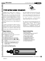
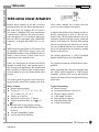
VHULHV/LQHDU$FWXDWRUV
Because these actuators do not have a built-in
position encoder, they are shorter than the equivalent 1100-series. For example, the 0.5" travel is
0.8" shorter! Although 1200-series construction
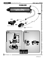
is similar to the 1100-series, the electrical connection is through an 18" two-conductor cable terminated in either a mono phone plug, MiniDIN8P
connector, or stripped and tinned wires [-A option].
OPEN-LOOP CONTROLLERS
While the phone plug adapts to TS Product’s line
of controllers with built-in velocity servos, the
MiniDIN8P interfaces to the SER3000-family of
Analog Velocity Servos. Tinned leads are for
connection to your controller/servo.
CLOSED-LOOP CONTROLLERS
Unless you incorporate an external A-QUAD-B
position encoding device, this actuator series is
only for open-loop applications. We typically find
these actuators in systems where an operator has
visual feedback to move into final position with a
joystick.
Two guiding slots on opposite sides of the housing prevent the motor from rotating as the lead-
CUSTOM SYSTEMS
PRICING
Major Features
! Shortest housing length
! Travels of ¼", ½", 1", 2", 4", 6", 8", 10",
12" [Custom=14", 16", 18"]
! Thrusts up to 300 lbs.
! Maximum velocity up to 17 mm/sec
! Pseudo-resolutions down to 1.8 in (45
m)
! Internal limit-of-travel/torque sensing
through optional SER3000 Analog Velocity Servo
! Vacuum-compatibility option
! Axial or side cable discharge
screw rotates. Marked keys in these slots also
serve as a coarse indicator of position.
A shaped and polished Nose Button provides a
precise contact point as well as a Reverse mechanical stop. The Forward mechanical stop is an
elastomer cushion inside the housing connected
directly to the leadscrew. The tabs in the guiding
slots do not provide any ends-of-travel. In this
way, the gearhead and motor are protected from
the severe mechanical forces created by running
into the ends-of-travel.
For pulling applications, a [-PPA] Push/Pull
Adaptor option replaces the Nose Button.
For vacuum environment, all lubricants are spacequalified.
When controlling the 1200-series through either
the 1200SC Speed Controller or 1200J Joystick
Controller, you have full velocity and direction
control with limit-of-travel sensing and backingoff the limit.
Typical Customizing
! Shorter housing
! Non-standard travels, such as 0.6"
! Thruster length variation
! Cable length variation
! Increased thrust capacity
! Adjustable thrust limit
! Custom Nose Button
TS Products, Inc.
LINEAR 20
VHULHV
GEARHEAD
! MicroMo 16/5 or 16/7 Gearhead
with ratios from 3.71:1 to
235,067:1 depending on space
available.
NOSE
BUTTON
WASHER
KEY
! Double-tabbed key holds the
gearhead from rotating and prevents choking sideloads created
by single-tabbed designs.
! Precision-ground stainless-steel
with either 32.3885 TPI or
40.0000 TPI pitch converts
rotary motion into linear movement ) bonded to gearhead output shaft with Loctite adhesive
rated at -65 oF to 300oF temperature range.
REVERSE
STOP
CUSHION
DRIVESHAFT
FORWARD
STOP
[Stop Shaft
Extension]
FORWARD
STOP
CUSHION
NOSE
MOUNTING
! Rigidly fixed on the Driveshaft,
this rotating piece stops forward
motion when it runs into the
Nose Mounting.
! Teflon or rubber donut produces
smooth, soft stops.
! Stationary phosphor-bronze nut
for Driveshaft. Outer mounting
threads are d-40 UNC.
HOUSING
CABLE
SCRAPER
CABLE
ENDCAP
CABLE
STRAIN
RELIEF
MOUNTING
NUT
! Rotating stainless-steel hemisphere (.200" Dia) contacts object being pushed ) also acts as
a Reverse stop. Polished; hardened by heat-treatment.
! Provides metal-to-metal contact
between Nose Button and Driveshaft to insure Nose Button
straightness and good dynamics.
! Teflon or rubber donut (depending on Actuator velocity) produces a soft stop.
! <1" O.D. black anodized body )
unanodized for vacuum compatibility.
! Thin disk keeps motor cable
from getting stuck.
! 1/8" O.D. cable-coil with 2
conds.
! Closes-up the actuator and provides strain-relief for the cable
going to the servo.
! Rubber sheath decreases the
possibility of damaging the Cable by bending.
! Nut with 0.55"O.D. secures the
actuator onto its mounting surface. I.D. has d-40" UNC
threads.
TS Products, Inc.
LINEAR 21
CLOSED-LOOP CONTROLLERS
NOSE
BUTTON
CUSTOM SYSTEMS
! MicroMo 1616, 1624, 1717, or
1724 motor with armature voltage
ranging from 3-24 volts (17,000
RPM maximum velocity).
MOTOR
PRICING
0(&+$1,&$/3$576'(6&5,37,21
OPEN-LOOP CONTROLLERS
ROTARY ACTUATORS LINEAR ACTUATORS
DC-Motor/Leadscrew-driven
OPEN-LOOP CONTROLLERS
LINEAR ACTUATORS ROTARY ACTUATORS
CLOSED-LOOP CONTROLLERS
CUSTOM SYSTEMS
PRICING
VHULHV
LINEAR 22
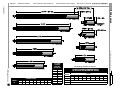
$9(5$*(:(,*+7
75$9(/
0.25"
0.5
1"
2"
4"
6"
8"
10"
12"
R]
3.6
3.8
4.2
4.9
6.1
7.4
8.5
9.7
10.9
6.3:1
1670:1
11.8:1
3101:1
22:1
5752:1
41:1
10683:1
76:1
19813:1
141:1
36796:1
262:1
68245:1
485:1
126741:1
900:1
235067:1
DC-Motor/Leadscrew-driven
TS Products, Inc.
6(5,(6
6WDQGDUG
$9$,/$%/(
*($55$7,26
See Ordering Information on Page 28.
+,*+(673266,%/(*($5+($'5$7,2
VHULHV3(5027253(575$9(/
MOTOR
TRAVEL
0.25"
0.5"
1"
1616
485
19813
68245
1624
11.8
141
485
2"
4"
6"
8"
10"
12"
68245 235067 235067 235067 235067 235067
485
1670
1717
Call Factory
1724
Call Factory
5752
5752
5752
1670
DC-Motor/Leadscrew-driven
TS Products, Inc.
75$9(/
ACTUAL-+.047
.027
0.25"
0.302
0.5"
0.530
1"
1.030
2"
2.030
4"
4.030
6"
6.030
8"
8.030
10"
10.030
12"
12.030
LINEAR 23
PRICING
CUSTOM SYSTEMS
CLOSED-LOOP CONTROLLERS
OPEN-LOOP CONTROLLERS
ROTARY ACTUATORS LINEAR ACTUATORS
VHULHV
NOMINAL
VHULHV
DC-Motor/Leadscrew-driven
LINEAR ACTUATORS ROTARY ACTUATORS
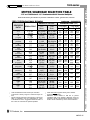
02725*($5+($'6(/(&7,217$%/(
RU0RWRUV*HDUKHDGV
6HULHV/LQHDU$FWXDWRU
RESOLUTION1
1616
Motor
1624
Motor
6.3
1.65 µm
65.1 µin
892 m
35.1 µin
480
18.6
256
10.2
140
5.49
75.2
2.96
40.5
1.59
21.8 m
859 in
11.8
463
6.34
250
3.41
134
1.84
72.4
991 m
39.0 in
534
21.0
288
11.3
155
6.11
83.5
3.29
45.0
1.77
.65-13 mm
26-510 mils
.35-7.1
14-280
.19-3.8
7.5-150
.10-2.1
4.0-81
.055-1.1
2.2-43
30-590 µm
1.2-23 mils
16-320
.63-13
8.6-170
.34-6.8
4.7-93
.18-3.7
2.5-50
.10-2.0
1.4-27
.053-1.1
.73-15 µm
29-570 µin
.39-7.8
15-310
.21-4.2
8.3-170
.11-2.3
4.5-90
.061-1.2
2.4-48
33-660 m
1.3-26 µin
18-360
.70-14
.50-10 mm
20-390 mils
.27-5.4
11-210
.14-2.9
5.7-110
.078-1.6
3.1-61
42-840 µm
1.7-30 mils
23-450
.90-18
12-240
.48-9.6
6.6-130
.26-5.2
3.6-71
.14-2.8
1.9-38
.075-1.5
1.0-21 µm
41-810 µin
.56-11
22-440
.30-6.0
12-240
.16-3.2
6.4-130
.089-1.7
3.7-74
47-940 m
1.9-37 µin
25-500
1.0-20
14-270
.54-11
11.8
[11.86420]
22
[22.03351]
41
[40.86557]
OPEN-LOOP CONTROLLERS
76
[75.89319]
141
[140.75917]
262
[261.40989]
485
[484.83713]
900
[900.41181]
1670
[1669.99451]
CLOSED-LOOP CONTROLLERS
3101
[3101.41837]
5752
[5752.20313]
10683
[10682.66295]
19813
[19813.14453]
36796
[36795.83984]
68245
[68245.27344]
CUSTOM SYSTEMS
126741
[126741.22210]
235067
[235067.04688]
2
PRICING
3
VELOCITY2 units/sec
GEARHEAD
RATIO
[6.39683]
1
/HDGVFUHZ 73,
Pseudo-resolution ) compared to 1000/1100series Linear Actuators with 60-count encoders.
Typical 20:1 velocity range for continuous motion.
@ max velocity (50% No-Load Velocity). Typical
variation of maximum load is ±35%. Suggested
minimum load is 7 lbs or 50% of maximum for
optimal operation.
4
5
6
MAXIMUM LOAD 3 (lbs)
1616 Motor
1624 Motor
Servo4 Stall5
Servo4 Stall5
.7
1.2
2.8
4.9
.32kgm
.54kgm
1.3kgm
2.2kgm
1.3
2.3
5.2
9.1
.59kgm
.91kgm
2.4kgm
4.1kgm
2.2
3.8
8.7
15
1.0kgm
1.7kgm
4.0kgm
6.9kgm
4.0
7.0
16
28
1.8kgm
3.2kgm
7.4kgm
13kgm
6.8
12
27
47
3.1kgm
5.4kgm
12kgm
21kgm
13
22
50
87
5.7kgm
10.kgm
23kgm
40kgm
21
36
566
1006
9.1kgm
17kgm
[84]
[150]
39
67
56
100
18kgm
31kgm
26kgm
45kgm
566
1006
[65]
[110]
56
100
56
100
56
100
26kgm
45kgm
56
100
56
100
56
100
56
100
56
100
56
100
56
100
56
100
56
100
56
100
56
100
56
100
56
100
56
100
56
100
56
100
While still inside a typical velocity servo window.
@ velocity = 0 (STALL).
Maximum thrust at STALL limited to 100 lbs to
protect gearhead from damage. Maximum thrust
at maximum velocity still within Servo Window is
56% of STALL thrust. Limitation by motor current reduction.
TS Products, Inc.
LINEAR 24
6HULHV/LQHDU$FWXDWRU
RESOLUTION1
1717
Motor
1724
Motor
3.71
2.85 µm
112 µin
767 m
30.2 µin
247
9.71
160
6.29
79.3
3.12
66.4
2.61
43.0
1.69
25.5
1.00
17.9 m
704 in
10.7
421
6.94
273
4.06
160
2.42
95.5
1.87
73.8
.86-17 mm
34-680 mils
.23-4.6
9.1-180
.075-1.5
2.9-59
48-970 µm
1.9-38 mils
24-480
.94-19
20-400
.79-16
13-260
.51-10
7.7-150
.30-6.1
5.4-110
.21-4.3
3.2-65
.13-2.6
2.1-42
.083-1.7
1.2-25 µm
48-970 µin
.73-15
29-580
.57-11
22-450
.53-11 mm
21-420 mils
.14-2.9
5.6-110
46-920 µm
1.8-36 mils
30-590
1.2-23
15-290
.58-12
12-250
.49-9.7
8.0-160
.32-6.3
4.7-95
.19-3.7
3.3-67
.13-2.6
2-40
.078-1.6
1.3-26
.051-1.0
.76-15 µm
30-590 µin
.45-9.0
18-360
.35-7.0
14-270
14
[13.7959]
43
[42.9206]
66
[66.2204]
134
[133.5309]
159
[159.4195]
246
[245.9615]
415
[415.4294]
592
[592.1296]
989
[988.8914]
1526
[1525.7182]
2608
[]
4365
[]
5647
[]
2
Pseudo-resolution due to No Encoder present.
Typical 20:1 velocity range for continuous-style motion.
@ max velocity (50% No-Load Velocity). Typical
variation of maximum load for 1200-series is ±35%.
Suggested minimum load is 7 lbs or 50% of maximum for optimal operation.
4
5
6
73,
MAXIMUM LOAD3 (lbs)
1716 Motor
Servo4 Stall5
1724 Motor
Servo4
Stall5
2.1
3.7
4.5
7.8
.95kgm
1.7kgm
2.kgm
3.5kgm
7.0
12
15
26
3.2kgm
5.5kgm
6.8kgm
12kgm
19
33
40
70
8.6kgm
15kgm
18kgm
32kgm
29
51
62
108
13kgm
23kgm
28kgm
49kgm
51
88
108
190
23kgm
77kgm
49kgm
85kgm
61
100
130
220
27kgm
48kgm
58kgm
100kgm
93
162
1656
3006
42kgm
73kgm
[200]
[340]
140
250
165
300
66kgm
110kgm
75kgm
140kgm
1656
3006
[210]
[360]
165
300
165
300
165
300
75kgm
140kgm
165
300
165
300
165
300
165
300
165
300
165
300
165
300
165
300
While still inside a typical velocity servo window.
@ velocity = 0 (STALL).
Maximum thrust limited to 300 lbs to protect gearhead teeth from damage. Maximum thrust at maximum velocity still within Servo Window is 56% of
STALL thrust. Limitation by motor current reduction.
PRICING
3
VELOCITY2 units/sec
GEARHEAD
RATIO
[]
1
/HDGVFUHZ
OPEN-LOOP CONTROLLERS
NOTE Contact factory for limitations on particular combinations of motor, gearhead ratio, and travel.
CLOSED-LOOP CONTROLLERS
RU0RWRUV*HDUKHDGV
CUSTOM SYSTEMS
02725*($5+($'6(/(&7,217$%/(
ROTARY ACTUATORS LINEAR ACTUATORS
VHULHV
DC-Motor/Leadscrew-driven
TS Products, Inc.
LINEAR 25
LINEAR ACTUATORS ROTARY ACTUATORS
OPEN-LOOP CONTROLLERS
CLOSED-LOOP CONTROLLERS
CUSTOM SYSTEMS
PRICING
LINEAR 26
DC-Motor/Leadscrew-driven
IDPLO\
TS Products, Inc.
IDPLOLHV
ROTARY ACTUATORS LINEAR ACTUATORS
Motor/Leadscrew-driven
PRICING
CUSTOM SYSTEMS
CLOSED-LOOP CONTROLLERS
OPEN-LOOP CONTROLLERS
Use the Interconnect Cables to extend the short
actuator cable to join the Servo or Controller.
Also use them to connect SER3000-series Servos to Controllers. While some standard lengths
are molded construction, the custom lengths are
hand-fabricated.
TS Products, Inc.
LINEAR 27
IDPLOLHV
Motor/Leadscrew-driven
LINEAR ACTUATORS ROTARY ACTUATORS
All Linear Actuators can be ordered with this number sequence )
6HULHV)7UDYHO)0RWRU6L]H)*HDUKHDG5DWLR)/HDGVFUHZ3LWFK)2SWLRQV
([DPSOH6'9
ACTUATOR
SERIES
Brushed DC
[Sensing Motor Conditions for
Limit-of-Travel]
1000 ! Closed- loop
! Non-rotating
thruster
! Robust, enclosed
1100 ! Closed-loop
! Shorter housing
! Rotating thruster
1200 ! Open-loop
! Shortest housing
! Rotating thruster
OPEN-LOOP CONTROLLERS
Stepping
[Integral Hall-effect Limit-ofTravel Sensors]
2000 ! Closed- loop
! Non-rotating
thruster
! Robust, enclosed
2100 ! Closed-loop
! Shorter housing
! Rotating thruster
2200 ! Open-loop
! Shortest housing
! Rotating thruster
Brushless DC
30002 ! Semi-custom
CLOSED-LOOP CONTROLLERS
1
-05 represents 0.05" travel.
-1 represents 1.0" travel.
TRAVEL1
(inches)
1000
-05
-1
-2
-4
-61
1100/1200
-025
-05
-1
-2
-4
-6
-8
-10
-12
$-142
2000
-05
-1
-2
-4
2100/2200
-025
-05
-1
-2
-4
MOTOR
SIZE
Brushed DC
-1616
-1624
-1717
-1724
Brushless DC
-35561
Stepping
-AM1524
GEARHEAD
RATIO
16/5-series for
brushed DC 1616
or 1624 motor
15/5-series for
AM1524 stepping
motor
-6.3
-1670
-11.8
-3101
-22
-5752
-41
-10683
-76
-19813
-141
-36796
-262
-68245
-485
-126741
-900
-235067
16/7-series for
brushed DC 1717
or 1724 motors
-3.71
-415
-14
-592
-43
-989
-66
-1526
-134
-2608
-159
-4356
-246
-5647
LEADSCREW
PITCH
-32
32.3885 TPI for
actuators )
1000
1100
2000
2100
-40
40.0000 TPI for
actuators )
1100
1200
2100
2200
OPTIONS
No dash designator for OPTIONS indicates STANDARD
CONFIGURATION with -NB1
Nose Button and axial discharge of control cable.
-B#
Boot
-B05 ½" travel
-B1 1" travel
-B2 2" travel
-NB# Nose Button
-NB1
-NB2
-NB3
-PPA
Short radius [std]
Long radius
Flat
Push/Pull Adaptor
-PP# Push Pad
-PP1 Hemispherical, short-radius
-PP2 Conical, short-radius
-PP3 Hemispherical, long- radius
-PP4 Conical, long-radius
-PP5 Flat
-S#a Custom modification designator
-SD Cable Side Discharge
[Axial Discharge is std]
-V
Vacuum Compatibility
-ZB Zero Backlash Gearhead
-CN# Connector
-CN1 MiniDIN8P (1000, 1100,
1200, 2200)
-CN2 DA-15P (2000, 2100)
-CN3 Mono 2.5mm Phone Plug
(1200)
-CN4 Tinned 18" Leads
-CN5 Ribbon & Header
(1000/1100)
2
Contact factory for additional information.
5(675,&7,21IRUVHULHV/LQHDU$FWXDWRUV
CUSTOM SYSTEMS
PRICING
&KRRVLQJD02725*($5+($'&RPELQDWLRQIRUDFHUWDLQ75$9(/
! The actuator’s housing is a fixed length for a given travel For example, a 0.5" travel 1200-series with1624 motor and
) we often make custom modifications.
900:1 gearhead will fit into a 1" housing.
! Motors and gearheads vary in length ) more powerful
motors and higher-ratio gearheads have longer length.
HIGHER GEARHEAD RATIOS
! Space is required for internal cable’s service-loop.
No matter what torque is available from the motor/gearTherefore, each TRAVEL has a maximum gearhead ratio
head combination, we limit the permissible maximum
for a particular motor as shown on pages 12, 18, and 22.
thrust to 100 lbs for the 16/5 gearhead. Higher thrust will
If you desire a combination beyond the limitation, you must
either damage individual gear teeth, the spur gear support
use )
rods, or severely reduce component lifetime. Since higher
1. A smaller motor.
gear ratios easily convert small motor torque into high
2. The next longer housing.
thrust exceeding 100 lbs, there is no reason to use the
3. Cable side discharge (-SD) without internal cable’s
more powerful but longer and slower 1624 motor since the
service-loop.
100 lb threshold has been already exceeded! (16/7 gearheads restricted to 300 lbs.)
TS Products, Inc.
LINEAR 28
STEPPINGMOTOR
PRECISION
MINIATURE
LINEAR
ACTUATORS
2000-Family
Micrometer
Replacement
Stepping
Motor
S
T
TS PRODUCTS, INC.
5550-2 North McGuire Road
Post Falls ID 83854-6506 USA
208-777-2771
FAX 208-777-9307
2100-series
Stepping-Motor/Leadscrew-driven
LINEAR ACTUATORS ROTARY ACTUATORS
SECTION CONTENTS
OPEN-LOOP CONTROLLERS
Stepping
Mechanical Specifications
2000-series . . . . . . . . . . . . . . . . 32
2100-series . . . . . . . . . . . . . . . . 33
2200-series . . . . . . . . . . . . . . . . 34
Cabling . . . . . . . . . . . . . . . . . . . 35
Ordering Information . . . . . . . . . . 36
Gearhead Selection Guide . . . . . 37
Performance . . . . . . . . . . . . . . . . . 38
Electrical Connection . . . . . . . . . 39
Engineering Reference . . . . . . . . 40
HOME Sensing . . . . . . . . . . . . . 40
Application Notes . . . . . . . . . . . . 42
Stepping Motor . . . . . . . . . . . . . 42
Accuracy . . . . . . . . . . . . . . . . . . 42
Resolution . . . . . . . . . . . . . . . . 43
Motor Controllers . . . . . . . . . . . 43
Drivers . . . . . . . . . . . . . . . . . . . 44
Low Temperature . . . . . . . . . . . 44
Vacuum Compatibility . . . . . . . . 44
Motor Comparison . . . . . . . . . . 45
CLOSED-LOOP CONTROLLERS
2200-series
2000-series
2100series
CUSTOM SYSTEMS
PRICING
S
TS Products, Inc. T
STEPPING 30
WHAT IS A STEPPING MOTOR LINEAR ACTUATOR?
OPEN-LOOP CONTROLLERS
! Travels to 4"
! Thrusts to 100 lbs.
! Velocities from 22 µin/sec to 0.82"/sec
! Resolutions from 2 nanoinches to 0.0002"
! Internal HOME sensor accurate to 10 µin
! End-of-Travel sensors with overtravel
! Adjusting Micrometer Replacement
2200-series
Coordinate control without
built-in encoder!
ACTUATOR PHYSICAL PARAMETERS
1
S
T
Approximate to mounting surface
¼"
½"
1"
2"
4"
Inches
Ounces
NA
NA
6.5
8.2
7.5
9.2
10.5
12.1
14.5
22.4
Inches
Ounces
4
4.6
4.5
4.8
5.2
5.3
6.2
6.3
8.2
8.3
Inches
Ounces
o
F
3.8
4.5
4
4.7
%
2
Approximate
3
4.5
5.5
5.2
6.2
-4 to +113
10-9 Torr3 to 3 Atmospheres
0 to 95
7.5
8.2
PRICING
Travel
2000-SERIES [Closed-loop]
Nominal Length1
Nominal Weight2
2100-SERIES [Closed-loop]
Nominal Length1
Nominal Weight2
2200-SERIES [Open-loop]
Nominal Length1
Nominal Weight2
Operating Temperature
Operating Air Pressure
Operating Relative Humidity
CLOSED-LOOP CONTROLLERS
In the 2000-series, a non-rotating nut moves
along the screw and pushes a non-rotating
plunger. In the 2100/2200-series, the screw
itself mates with a threaded Nosepiece and
rotates as it protrudes from the cylinder.
2000-Series
Closed-loop operation
Integral position encoder
Non-rotating plunger
2100-Series
Closed-loop operation
Integral position encoder
Rotating plunger
Push/Pull capability
Short housing
2200-Series
Open-loop operation
Rotating plunger
Push/Pull capability
Shortest housing
CUSTOM SYSTEMS
The 2000-family uses an Arsape Stepping
Motor and leadscrew/nut to convert the
motor's rotation into linear movement up to
4". Stepping motors enable open-loop coordinate control without an encoder. The 2000,
2100, and 2200 series produce a controlled
thrusting movement by moving a plunger in
and out of one end of a 1" OD cylinder.
Eighteen different gearhead ratios provide a
variety of thrusts, velocities, and resolutions.
ROTARY ACTUATORS LINEAR ACTUATORS
2100-series
Stepping-Motor/Leadscrew-driven
Order-V Option
TS Products, Inc.
STEPPING 31
2000-series
LINEAR ACTUATORS ROTARY ACTUATORS
AVAILABLE
GEAR
RATIOS
Stepping-Motor/Leadscrew-driven
TRAVEL
AVERAGE
WEIGHT
(oz.)
0.5"
8.2
15/5
MOTOR
HOUSING
DIM
#1
14.303
#2
14.553 ±.020
#3
14.803
MOTOR
HOUSING
DIM
#1
10.303
#2
10.553 ±.020
#3
10.803
TOL
4" TRAVEL
TOL
6.3:1
11.8:1
22:1
41:1
76:1
1"
9.2
2"
12.1
4"
22.4
DIM
#1
7.303
#2
7.553
#3
7.803
MOTOR
HOUSING
DIM
#1
6.303
#2
6.553
#3
6.803
141:1
262:1
2" TRAVEL
MOTOR
HOUSING
485:1
TOL
±.020
OPEN-LOOP CONTROLLERS
900:1
1,670:1
3,101:1
PERMITTED
MOTOR/GEARHEAD
COMBINATIONS
5,752:1
10,683:1
19,813:1
36,796:1
68,2451
126,741:1
235,067:1
MOTOR SIZE
MOTOR
HOUSING
1524
HIGHEST POSSIBLE
GEAR RATIO
#1
#2
#3
485:1
1" TRAVEL
TOL
±.020
19,813:1
235,067.1
0.5" TRAVEL
CLOSED-LOOP CONTROLLERS
0.5" TO 2" TRAVEL
1.781±.005
.550±.010 OD
MOUNTING NUT
.656±.005
.150±.010
.110 +.049
- .044
@ REVERSE LIMIT
.1875 ±.0002 OD
PLUNGER
ACTUATION
.990 ±.010 OD
.2000±.0005 Spherical OD
PLUNGER TIP
4" TRAVEL
@ REVERSE LIMIT
.060±.010 Radius
.375-40 UNS-2A Thd.
CUSTOM SYSTEMS
.620 +.000
- .005 OD
.656 +.005
- .007
.150±.010
.1875 ±.0002 OD
PLUNGER
Range of Mounting
Plate Thickness
.255 to .491
.990 ±.010 OD
.2000±.0005 Spherical OD
PLUNGER TIP
.375-40 UNS-2A Thd.
PRICING
.550±.010 OD
MOUNTING NUT
Range of Mounting
Plate Thickness
.255 to .489
S
TS Products, Inc. T
STEPPING 32
S
T
PRICING
5752:1
10683:1
19813:1
36796:1
68245:1
126741:1
235067:1
22:1
41:1
76:1
141:1
262:1
485:1
900:1
CLOSED-LOOP CONTROLLERS
IN
1
TS Products, Inc.
STEPPING 33
OPEN-LOOP CONTROLLERS
11.8:1
41:1
2"
4"
485:1
1670:1
1670:1
1"
0.5"
0.25"
TRAVEL
7.701
5.701
4.701
4.201
3.951
GEAR
RATIO
˜X
8.442
6.442
5.442
4.942
4.692
GEAR
RATIO
šX
"A"±.020
8.3
6.3
5.3
4.8
4.6
AVERAGE
WEIGHT
(oz.)
ROTARY ACTUATORS LINEAR ACTUATORS
IN
CUSTOM SYSTEMS
3101:1
11.8:1
"X"
(Critical
Gear
Ratio)
.5
1670:1
0
6.3:1
AVAILABLE GEAR
RATIOS
Stepping-Motor/Leadscrew-driven
2100-series
CUSTOM SYSTEMS
3101:1
5752:1
10683:1
19813:1
36796:1
68245:1
126741:1
235067:1
22:1
41:1
76:1
141:1
262:1
485:1
900:1
CLOSED-LOOP CONTROLLERS
PRICING
STEPPING 34
485:1
41:1
1"
2"
7.243
5.243
4.243
4.743
3.493
7.701*
5.701
4.701
4.201
3.951
GEAR
RATIO
šX
"A" ±.020
8.3
6.3
5.3
4.8
4.6
AVERAGE
WEIGHT
(oz.)
* This dimension is 8.442 with a
3101:1 or higher gear ratio.
11.8:1
1670:1
0.5"
4"
19813:1
0
GEAR
RATIO
˜X
IN
0.25"
"X"
(Critical
Gear
Ratio)
1
11.8:1
TRAVEL
OPEN-LOOP CONTROLLERS
IN
1670:1
.5
6.3:1
LINEAR ACTUATORS ROTARY ACTUATORS
AVAILABLE GEAR
RATIOS
2200-series
Stepping-Motor/Leadscrew-driven
S
TS Products, Inc. T
2000-family
Stepping-Motor/Leadscrew-driven
ROTARY ACTUATORS LINEAR ACTUATORS
CABLING
f .146 ±.003
Actuator Cable
OPEN-LOOP CONTROLLERS
CN2
CN1
OR
2000 and 2100-Series
Connector Mating Surface Line
2200-Series
CN2
CN1
CLOSED-LOOP CONTROLLERS
15-pin Subminiature "D" Connector
DA-15
(Only 12 circuits active)
8-pin MiniDIN Plug
f .146±.003
Actuator Cable
2.0
.54±.02
CUSTOM SYSTEMS
.24
1.46±.06
.54±.02
1.31
.49
f .120 Typ
1.54
TOLERANCE
S
T
.X
.XX
.XXX
± .2
± .01
± .005
PRICING
unless noted
(All dimensions in inches)
TS Products, Inc.
STEPPING 35
2000-family
Stepping-Motor/Leadscrew-driven
LINEAR ACTUATORS ROTARY ACTUATORS
ORDERING GUIDE
Order number example )
2100-1-AM1524-262-32-SD
NOSE BUTTON Options
-NB1
Short Radius [Std.]
-NB2
Long Radius
-NB3
Flat
-PPA
Push/Pull Adaptor
OPEN-LOOP CONTROLLERS
ACTUATOR SERIES
2000 ! Closed-loop
! Non-rotating thruster
! Robust, enclosed
2100 ! Closed-loop
! Shorter housing
! Rotating thruster
2200 ! Open-loop
! Shortest housing
! Rotating thruster
TRAVEL Options
2000
Travel
½"
-05
1"
-1
2"
-2
4"
-4
CLOSED-LOOP CONTROLLERS CUSTOM SYSTEMS PRICING
MOTOR STYLE
-AM1524
2100/220
0
-025
-05
-1
-2
-4
Travel
¼"
½"
1"
2"
4"
OPTIONS
2000 2100 2200
-B
Boot
)
T
T
-NB# Nose Button
)
T
T
-PP# Push Pad
T
T
T
-SD
Side Discharge T
T
T
-V
Vacuum
T
T
T
Compatible
-ZB
Zero Backlash
T
T
T
Gearhead
PUSH PAD Options
-PP1
Hemispherical, Short-Radius
-PP2
Hemispherical, Long-Radius
-PP3
Conical, Short-Radius
-PP4
Conical, Long-Radius
-PP5
Flat
Arsape Stepping Motor
24 Full-steps/rev
Current mode (250mA max)
GEARHEAD RATIO 15/5 Options
-6.3
:1
-262
:1
-10683
-11.8
:1
-485
:1
-19813
-22
:1
-900
:1
-36796
-41
:1
-1670
:1
-68245
-76
:1
-3101
:1
-126741
-141
:1
-5752
:1
-235067
IMPORTANT NOTICE
:1
:1
:1
:1
:1
:1
LEADSCREW Options
2000
T
-32
2100
T
2200
T
T
)
[32.3885 TPI]
-40
)
[40.0000 TPI]
Not all combinations of motor, gearhead ratio, and travel
are possible in the standard unmodified housing. Please
see selection guidance charts on the pages of mechanical
drawings.
S
TS Products, Inc. T
STEPPING 36
S
T
32.3885 TPI 40.0000 TPI 32.3885 TPI 40.0000 TPI
20002/21003 21003/22004 2000/2100
MAXIMUM
LOAD
@4000 fsps
lbs
2000/2100 2100/2200
VELOCITY
@250mA
4000 sps1
2000/2100
2100/2200
6.3
(6.39683)
5.11 µm
201.1 µin
4.14 µm
162.8 µin
2.04 µm
80.4 µin
1.65 µm
65.1 µin
100
2505
500
1
2
4
1
3
6
20.8 mm/sec
820 mils/sec
16.9 mm/sec
664 mils/sec
11.8
(11.86420)
2.75
108.4
2.23
87.8
1.10
43.4
892 nm
35.1 µin
100
250
500
2
4
8
2
5
10
11.1
437
9.0
354
22.
(22.03351)
1.48
58.4
1.20
47.3
593 nm
23.4 µin
480
18.6
100
250
500
3
7
14
3
8
16
6.0
235
4.8
190
41.
(40.86557)
800 nm
31.5 µin
648 nm
25.5 µin
320
12.6
256
10.2
100
250
500
5
13
26
6
15
30
3.2
127
2.6
102
76.
(75.89319)
430
16.9
348
13.7
172
6.78
140
5.49
100
250
500
9
23
46
10
25
50
1.7
68
1.4
55
141.
(140.75917)
232
9.13
188
7.40
92.9
3.66
75.2
2.96
100
250
500
17
43
85
18
46
92
940 µm/sec
37 mils/sec
762 µm/sec
30 mils/sec
262.
(261.40989)
125
4.92
101
3.98
50.0
1.97
40.5
1.59
100
250
500
30
74
1006
31
77
1006
508
20
406
16
485.
(484.83713)
67.4
2.66
54.6
2.15
27.0
1.06
21.8 nm
859 nin
100
250
500
56
1006
100
57
1006
100
269
10.6
218
8.6
900.
(900.41181)
36.4
1.43
29.5
1.16
14.5 nm
571 nin
11.8
463
100
250
500
1006
100
100
1006
100
100
145
5.7
117
4.6
1670.
(1669.99451)
19.5 nm
771 nin
7.83
308
6.34
250
100
250
500
100
100
100
100
100
100
78.7
8.1
63.5
2.5
3101.
(3101.41837)
10.53
415
8.53
336
4.21
166
3.41
134
100
250
500
100
100
100
100
100
100
40.6
1.6
33.0
1.3
5752.
(5752.20313)
5.68
224
4.60
181
2.27
89.5
1.84
72.4
100
250
500
100
100
100
100
100
100
22.9 µm/sec
902 µin/sec
18.5 µm/sec
730 µin/sec
10683.
(10682.66295)
3.06
120
2.48
97.5
1.22
48.2
991 pm
39.0 nin
100
250
500
100
100
100
100
100
100
12.2
482
9.9
390
19813.
(19813.14453)
1.65
65.0
1.34
52.6
660 pm
26.0 nin
534
21.0
100
250
500
100
100
100
100
100
100
6.6
259
5.3
210
36796.
(36795.83984)
888 pm
35.0 nin
719 pm
28.3 nin
355
14.0
288
11.3
100
250
500
100
100
100
100
100
100
3.5
136
2.8
110
68245.
(68245.27344)
480
18.9
389
15.3
192
7.54
155
6.11
100
250
500
100
100
100
100
100
100
1.9
75
1.5
61
126741.
(126741.22210)
258
10.15
209
8.22
103
4.06
83.5
3.29
100
250
500
100
100
100
100
100
100
1.0
41
838 nm/sec
33 µin/sec
235067.
(235067.04688)
140
5.47
113
4.43
55.6
2.19
45.0
1.77
100
250
500
100
100
100
100
100
100
559 nm/sec
22 µin/sec
457
18
15.8 nm
624 nin
Velocity for estimated Maximum Mechanical Power Point. You can run the motor faster but with less load capacity.
All 2000-series have 32.38853 TPI leadscrew.
2100-series can have either 32.38853 or 40 TPI leadscrew.
All 2200-series have 40.0000 TPI leadscrew.
Factory-specified maximum continuous current in one winding only = 250 mA
User must further limit the motor current to prevent exceeding 100 lbs of thrust.
PRICING
1
2
3
4
5
6
2100
C
U
R
R
E
N
T
mA
CLOSED-LOOP
15-count encoder @ 4X
OPEN-LOOP CONTROLLERS
nominal
(actual)
OPEN-LOOP
24 full steps/rev
CLOSED-LOOP CONTROLLERS
RESOLUTION
GEARHEAD
RATIO
15/5
CUSTOM SYSTEMS
GEARHEAD RATIO SELECTION TABLE
ROTARY ACTUATORS LINEAR ACTUATORS
2000-family
Stepping-Motor/Leadscrew-driven
TS Products, Inc.
STEPPING 37
IDPLO\
Stepping-Motor/Leadscrew-driven
LINEAR ACTUATORS ROTARY ACTUATORS
MAXIMUM LOAD for step synchronization
as a function of motor winding current for
various FULL-STEP velocities.
NOTES
1. MAXIMUM LOAD = load causing step
error.
2. INTERMITTENT MAXIMUM CURRENT)
ON for less than 10 seconds with 10
seconds OFF minimum!
3. For 250 mA values, motor operated with
3.125 Vdc maximum voltage.
OPEN-LOOP CONTROLLERS
MAXIMUM LOAD to retain
step synchronization as a
function of motor winding current for various HALF-STEP
velocities
CLOSED-LOOP CONTROLLERS
MAXIMUM LOAD to retain
step synchronization as a
function of Acceleration for
various motor winding currents
and step sizes
CUSTOM SYSTEMS
MAXIMUM LOAD Supported in Power
OFF Condition comparing 2000-family
with 1000-family Linear Actuators 1
1
Only applies during severe multi-G vibration.
Under normal static conditions, internal
friction always exceeds external force thus
preventing all spurious movement for both
stepping and DC motors.
PRICING
NOTE ) Proportionally scale performance data by gear ratio for other actuators.
TS Products, Inc.
STEPPING 38
!
!
!
!
!
Open-collector
Active low
TTL/CMOS
Hysteresis
Overtravel
67(33,1*027253+<6,&$/3$5$0(7(56
(/(&75,&$/3$5$0(7(56
$1*8/$5$&&85$&<
3KDVHUHVLVWDQFH
S
3KDVHLQGXFWDQFH#.]
P+
1RPLQDOSKDVHFXUUHQW
$
5RWRULQHUWLD
1RPLQDOVLQJOHSKDVHFXUUHQW
$
0D[LPXPUDGLDOORDG
9NVWHSVVHFRQG
0D[LPXPD[LDOORDG
%DFN(0)DPSOLWXGH
72548(3$5$0(7(56:,7+%,32/$5'5,9(5
$EVROXWHDQJXODU)SKDVHV21
LQ
+ROGLQJWRUTXH)[QRPLQDOFXUUHQW
R]LQ
27+(53$5$0(7(56
'HWHQWSOXVIULFWLRQWRUTXH
R]LQ
'LHOHFWULF7HVWV)IRUPLQXWH
5HVRQDQFHIUHTXHQF\
&:
R
$PELHQWZRUNLQJWHPSHUDWXUH
R
7KHUPDOWLPHFRQVWDQW
STEPPING-MOTOR
TECHNICAL
ASSISTANCE
)
(OHFWULFDOWLPHFRQVWDQW
1RPLQDODFFHOHUDWLRQ
& WR :HLJKW
VHFRQGV
$UVDSH)DFWRU\
5HSUHVHQWDWLYH
'LVWULEXWRU
0D[LPXPD[LDOSOD\)#1HZWRQV
0D[LPXPFRLOWHPSHUDWXUH
OEV
OEV
R
NJP @
LQ
R]LQ
7KHUPDOUHVLVWDQFHFRLODLU
0D[LPXPUDGLDOSOD\)#1HZWRQV
1RPLQDOKROGLQJWRUTXH)SKDVHV21
7+(50$/3$5$0(7(56
RI)XOO6WHS
0(&+$1,&$/3$5$0(7(56
6WHSDQJOH
'RQRYDQ0LFUR7HN,QF
9LVWD/DJR'ULYH
6LPL9DOOH\&$
9RLFH )$;
9UPV
+]
6
NUDGVVHF R]
GHJUHHVRIDUF
'LVWULEXWRU
OPEN-LOOP CONTROLLERS
HALL-EFFECT
HOME/LIMIT
SENSORS
CLOSED-LOOP CONTROLLERS
NOTE
The wiring schematics shown on
this page represent )
! 2000-x-AM1524-76 and
! 2200-x-AM1524-262 only.
Other gearhead ratios and actuator styles have modified wiring
to produce identical thruster
movement for the same controller sequence.
CUSTOM SYSTEMS
MiniDIN 8-pin
Circuit
Function
1
Motor Phase A+
2
Motor Phase A3
Motor Phase B+
4
Motor Phase B5
Sensor Supply
6
Sensor Return
7
Forward Limit Sensor
8
Reverse Limit Sensor
(/(&75,&$/&211(&7,216
Subminiature DA-15P
2200-Series
Circuit
Function
1
Sensor Supply
2
Sensor Return
3
Motor Phase A+
4
Motor Phase A5
Motor Phase B+
6
Motor Phase B7
Encoder Phase A
8
Encoder Phase B
9
Forward Limit Sensor
10
Reverse Limit Sensor
11
Encoder Return
12
Encoder Supply
13
NC
14
NC
15
NC
0LFUR0R(OHFWURQLFV,QF
6HFRQG$YHQXH6
6W3HWHUVEXUJ)/
9RLFH )$;
TS Products, Inc.
STEPPING 39
PRICING
2000/2100-Series
ROTARY ACTUATORS LINEAR ACTUATORS
IDPLO\
Stepping-Motor/Leadscrew-driven
!
!
!
!
!
Open-collector
Active low
TTL/CMOS
Hysteresis
Overtravel
67(33,1*027253+<6,&$/3$5$0(7(56
(/(&75,&$/3$5$0(7(56
$1*8/$5$&&85$&<
3KDVHUHVLVWDQFH
S
3KDVHLQGXFWDQFH#.]
P+
1RPLQDOSKDVHFXUUHQW
$
5RWRULQHUWLD
1RPLQDOVLQJOHSKDVHFXUUHQW
$
0D[LPXPUDGLDOORDG
9NVWHSVVHFRQG
0D[LPXPD[LDOORDG
%DFN(0)DPSOLWXGH
72548(3$5$0(7(56:,7+%,32/$5'5,9(5
$EVROXWHDQJXODU)SKDVHV21
LQ
+ROGLQJWRUTXH)[QRPLQDOFXUUHQW
R]LQ
27+(53$5$0(7(56
'HWHQWSOXVIULFWLRQWRUTXH
R]LQ
'LHOHFWULF7HVWV)IRUPLQXWH
5HVRQDQFHIUHTXHQF\
&:
R
$PELHQWZRUNLQJWHPSHUDWXUH
R
7KHUPDOWLPHFRQVWDQW
STEPPING-MOTOR
TECHNICAL
ASSISTANCE
)
(OHFWULFDOWLPHFRQVWDQW
1RPLQDODFFHOHUDWLRQ
& WR :HLJKW
VHFRQGV
$UVDSH)DFWRU\
5HSUHVHQWDWLYH
'LVWULEXWRU
0D[LPXPD[LDOSOD\)#1HZWRQV
0D[LPXPFRLOWHPSHUDWXUH
OEV
OEV
R
NJP @
LQ
R]LQ
7KHUPDOUHVLVWDQFHFRLODLU
0D[LPXPUDGLDOSOD\)#1HZWRQV
1RPLQDOKROGLQJWRUTXH)SKDVHV21
7+(50$/3$5$0(7(56
RI)XOO6WHS
0(&+$1,&$/3$5$0(7(56
6WHSDQJOH
'RQRYDQ0LFUR7HN,QF
9LVWD/DJR'ULYH
6LPL9DOOH\&$
9RLFH )$;
9UPV
+]
6
NUDGVVHF R]
GHJUHHVRIDUF
'LVWULEXWRU
OPEN-LOOP CONTROLLERS
HALL-EFFECT
HOME/LIMIT
SENSORS
CLOSED-LOOP CONTROLLERS
NOTE
The wiring schematics shown on
this page represent )
! 2000-x-AM1524-76 and
! 2200-x-AM1524-262 only.
Other gearhead ratios and actuator styles have modified wiring
to produce identical thruster
movement for the same controller sequence.
CUSTOM SYSTEMS
MiniDIN 8-pin
Circuit
Function
1
Motor Phase A+
2
Motor Phase A3
Motor Phase B+
4
Motor Phase B5
Sensor Supply
6
Sensor Return
7
Forward Limit Sensor
8
Reverse Limit Sensor
(/(&75,&$/&211(&7,216
Subminiature DA-15P
2200-Series
Circuit
Function
1
Sensor Supply
2
Sensor Return
3
Motor Phase A+
4
Motor Phase A5
Motor Phase B+
6
Motor Phase B7
Encoder Phase A
8
Encoder Phase B
9
Forward Limit Sensor
10
Reverse Limit Sensor
11
Encoder Return
12
Encoder Supply
13
NC
14
NC
15
NC
0LFUR0R(OHFWURQLFV,QF
6HFRQG$YHQXH6
6W3HWHUVEXUJ)/
9RLFH )$;
TS Products, Inc.
STEPPING 39
PRICING
2000/2100-Series
ROTARY ACTUATORS LINEAR ACTUATORS
IDPLO\
Stepping-Motor/Leadscrew-driven
IDPLO\
Stepping-Motor/Leadscrew-driven
LINEAR ACTUATORS ROTARY ACTUATORS
Home Sensing Accuracy
OPEN-LOOP CONTROLLERS
CLOSED-LOOP CONTROLLERS
Providing an accurate, repeatable HOME point is
difficult. Although the Linear Actuators can provide
an incremental resolution of a few nanoinches,
traditional mechanical switches for limit-oftravel/home sensing are only accurate to a few mils
at best. This means the HOME point could be in
error by 500,000 resolution elements! However, the
2000-family uses Hall-effect switches for limit-oftravel and Home sensors. While the Hall-effect
devices are much more accurate than mechanical
switches, they still exhibit inaccuracies from the
following sources:
! Differential thermal expansion in the actuator
mechanical structure,
! Hall-effect switch temperature sensitivity,
! Losing step synchronism under an excessive
load,
! Microstep uncertainty under load,
! Variable biasing from stray magnetic fields,
! Mechanical vibration and distortion,
represents the apparent displacement of the
thruster’s Nose Button at both the FORWARD and
REVERSE HOME sensor as the temperature
changes.
1. Differential thermal expansion of dissimilar
materials
In contrast to the stainless steel leadscrew, the
actuator’s housing is aluminum. The limit sensors
are on the housing and the tripping magnets move
with the leadscrew. Therefore, due to differential
thermal expansion of these dissimilar metals, the
position varies by temperature as a function of
actuator travel.
Internal housing temperature increase from running motor:
Since stepping motors continuously consume high
current whether running fast or slow, they pump
heat into the leadscrew and housing. Because it is a
localized source of heat, the motor itself can produce distortions as the actuator temperature advances toward equilibrium.
CUSTOM SYSTEMS
In the 2000-series structure, the housing-toleadscrew joint is closest to the Reverse Limit
sensor. In contrast, in the 2100/2200-series structure, the housing-to-leadscrew joint is far away
from the Reverse Limit sensor.
We calculated the following information from
known coefficients of thermal expansion for the
various materials used in the actuators. The error
THRUSTER POSITION ERROR in µin
versus oC CHANGE in TEMPERATURE
TRAVEL
¼"
½"
1"
2"
4"
2000-series
Reverse
na
-23
-31
-46
-77
Forward
na
-7
-4
3
17
2100/2200-series
Reverse
+6
+3
-2
-13
-36
Forward
+16
+19
+24
+36
+58
+
Positive means that when you return to the Home switch, the Nose Button
will be IN FRONT of where it was prior to the temperature change.
-
Negative means that the Nose Button will be BEHIND where it was prior to
the temperature change.
For example, on a 2200-1 Linear Actuator )
! Simply holding an actuator in your hand can
cause a 1-2 mil change in limit position. This
can easily be 80 full-steps of the motor.
! Quick temperature changes can expand/contract housing by 1-2 mils )
1. Attaching to a cold plate,
2. Holding in a warm hand,
3. Contacting a work surface.
PRICING
TS Products, Inc.
STEPPING 40
Operating Environment
To produce actuator resolution comparable
with Hall-effect Switch accuracy, we make
the following practical suggestions )
! Air temperature within ±½ oF,
! Laminar air flow,
! Mount to heat conductor,
! Prohibit mechanical vibration,
! No touching of housing with hand.
! No variable pressure on housing.
4. Microstep Inaccuracy Under Load
Microstepping motor drivers vary the magnetic
stator pole strengths to balance the rotor teeth
somewhere between the cardinal steps. With many
microstep subdivisions, the torque difference
between adjacent microsteps may be smaller than
system friction and load and the actuator will not
move.
Without external torque, a stepping motor's rotor is
in a stable resting position compared to the stator.
To hold a stepping motor's rotor in place against an
external torque, the magnets generate a larger
opposing torque as the displacement between rotor
and stator becomes larger. The greater the displacement ) the greater the torque. If the external torque
5. Variable Biasing from
Stray Magnetic Fields
Although the external
magnetic fields may not be
strong enough to trip the
sensor, any field will move
the trip point.
6. Mechanical Vibration
and Distortion
Although the actuator housing is mechanically
robust, you can easily experience HOME position
errors while the housing flexes under an external
driving mechanical vibration.
Switch Accuracy
With all factors being stable, the Hall-Effect
Switch repeats within 10µin (0.4µm) ) other
error sources can often be an order of
magnitude larger.
TS Products, Inc.
STEPPING 41
OPEN-LOOP CONTROLLERS
3. Losing Step
Synchronism under
Excessive Load
Typical of all stepping motors, if the external load
exceeds the thrust capacity
of the Linear Actuator, the
motor will lose position by
4-step multiples. Under
these conditions, HOME is
not repeatable.
If the external load is high enough, the motor may
not even move. It may even rotate away from its expected position until the torque generated by the
displacement exceeds the
torque required.
CLOSED-LOOP CONTROLLERS
2. Hall-effect Switch Temperature Sensitivity
The 2000-family Linear Actuators use the Allegro
Model 3122 Hall-Effect Switch. Its operating point
can vary 5 µin/oC.
Similarly, to move against an external torque, the
motor must generate a larger torque. This torque is
a function of both the offset between the rotor and
its rest state as well as the relative current differences between the poles. When microstepping,
maximum available torque for a fixed current
occurs at the normal full-step detents. At the electronically-created microsteps between the full-steps,
the number of steps correspondingly reduces the
available torque.
CUSTOM SYSTEMS
70oF±10oF
21oC±5oC
Actuator style
2200-01-AM1524-41
Microstepping
8x
o
Change 10 F room warm-up over 30 minutes
Result
Moved REVERSE sensor's effective
position by 700 µin (17.8 µm).
Change Holding in hand
Result
FORWARD LIMIT
= 200 µin.
REVERSE LIMIT
= 1500 µin.
PRICING
is higher than the motor's maximum torque, the
rotor will slip to the next detent position.
Typical Experimental Data
Initial Conditions
Temperature
ROTARY ACTUATORS LINEAR ACTUATORS
IDPLO\
Stepping-Motor/Leadscrew-driven
IDPLO\
LINEAR ACTUATORS ROTARY ACTUATORS
STEPPING MOTOR
Theory of Operation
The AM1524-24-A-0.25-12.5 Stepping Motor has
two phases and operates best from bipolar drivers.
Its winding resistance is a low 12.5 ohms for
continuous current operation not exceeding 0.25A
for both phases ON simultaneously. During halfstepping, the single phase ON can be 0.35A without
damage to the motor under normal conditions.
OPEN-LOOP CONTROLLERS
MicroStepping
In single-phase FULL STEP operation, an opposing
pair of magnetic rotor teeth line up with the energized stator electro-magnets. To control a stepping
motor in FULL STEP mode, the adjacent pair of
electromagnets is energized to attract the rotor teeth
to a new FULL STEP position. In dual-phase FULL
STEP operation, all stator poles are active and of
the correct magnetic polarity to cause rotation and
maximum torque.
CLOSED-LOOP CONTROLLERS
In HALF STEP operation, the phases alternate
between both ON and only one ON. To provide
constant torque with only one phase ON, motor
drivers often raise the current by 50%.
In microstepping operation, the electromagnets are
not fully-switched. Instead, the magnetic strength is
less than full thus causing the rotor to balance
somewhere between the stator poles. The accuracy
of microstepping is a function of field strength
repeatability as well as uniformity of the electromagnets.
CUSTOM SYSTEMS
PRICING
Dropping Steps
If the external load is too high for either starting
velocity, acceleration rate, motor current, or running
velocity, the motor can fail to take a step. After the
step failure, its new position will be in error by
multiple rotor teeth positions or 4 Full Steps for
each tooth.
Stepping-Motor/Leadscrew-driven
RECOMMENDATIONS
Arsape recommends no more than 4x microstepping. Because of the exact mechanical
structure of the AM1524 motor, you cannot
realize the assumed increased positioning
accuracy. We have tested the motor at FullStep, Half-Step, 2x, 4x, 8x, and 16x microstepping with satisfactory results )
POSITIONING ACCURACY
Ranked from Most Important
±400µin max.
! Leadscrew Pitch
(±5µm)
Irregularity
The nominal leadscrew has a peak-topeak wobble equivalent to 10µm of linear
distance.
! Thermal
Expansion
15µin/EC average
Thruster 25µin/EC per 1" of exposed leadscrew.
Reverse Limit 15µin/EC per 1" of
travel.
Forward Limit 3µin/EC independent
of travel
! Mechanical
Distortion
! Gear Eccentricity
External forces on the
actuator housing cause
deformations and
metal compression ) a
function of force amplitude and direction.
Unknown but finite
eccentricity.
TS Products, Inc.
STEPPING 42
0.25A
0.35A
The principal concern with excessive motor
current is a temperature rise in the motor windings. High temperature will burn-off insulation
causing winding shorts and distort the rotor
bearings. In the Linear Actuator package, the
heat conduction path is through the Gearhead
Housing-to-Leadscrew-to-Nose
Mounting/Housing-to- mounting plate. The heat
also radiates from the motor-to-Housing-to-air.
A second conduction path is Motor-to internal
air-to Housing-to external air.
Minimum Velocity
There is no minimum velocity!
Maximum Velocity
The motor’s electrical time constant limits
maximum velocity and depends on the winding
inductance. By attempting to move the rotor
faster and faster, the available driving energy
decreases less because of the dynamic resistance
of the windings. While the Maximum Power
Point is at 4000 steps per second (our recommended maximum velocity), the motor can
operate at 10,000 steps per second with reduced
maximum output torque.
MOTOR CONTROLLERS
Controller
A typical Controller is a dedicated microprocessor-based computer with an accurate time base.
Its low-level function is to prepare step and
direction signals to start, accelerate, run, decelerate, and stop one or more stepping motors. Its
high-level functions may include )
1. Synchronization of multiple motors.
2. Closed-loop encoder management.
3. Control or sensing of other machine
events.
4. Operator’s console.
Controllers are available in the following configurations )
1. Stand-alone or Computer-interface with
RS-232 and/or IEEE-488 communications.
Examples:
1. Centent Company
2. Compumotor
3. Motion Science Inc.
2. Bus-based ) IBM-PC, VME, STD.
Examples:
1. AMSI
2. Motion Engineering, Inc.
3. Motion Science Inc.
4. Drive
5. Precision MicroControl
3. PLC-based
TS Products, Inc.
STEPPING 43
ROTARY ACTUATORS LINEAR ACTUATORS
Winding Current @25EC
Two phases ON simultaneously
One phase ON
OPEN-LOOP CONTROLLERS
Setting Up the Motor Driving Parameters
Acceleration
See Performance Graph on Page Stepping 38. Use
proportional scaling for other actuators.
Step Interval
Full
Half
Micro<8X
CLOSED-LOOP CONTROLLERS
In the best of conditions, the actuator is repeatable
within the resolution. However, thermal drift,
backlash, and load variations influence repeatability.
Maximum Starting Velocity is a function of load.
For a given load, this velocity will move the actuator without dropping rotor steps. Please see Performance Graph on Page Stepping 38. Use proportional scaling for other actuators.
CUSTOM SYSTEMS
POSITIONING RESOLUTION
Resolution relates to the number of steps per linear
distance. It represents the minimum controllable
movement and is a function of leadscrew pitch,
gearhead ratio, and the motor steps per revolution.
It is not a measure of absolute accuracy.
IDPLO\
PRICING
Stepping-Motor/Leadscrew-driven
IDPLO\
Stepping-Motor/Leadscrew-driven
LINEAR ACTUATORS ROTARY ACTUATORS
Driver
Drivers deliver electrical power to motor in
response to signals from the Controller. Typical
signals are step pulses and direction level. It
contains the logic to drive motors in full-step,
half-step, or microsteps.
OPEN-LOOP CONTROLLERS
CLOSED-LOOP CONTROLLERS
Bipolar Recirculating Chopper
(Power Dumping not necessary because the
motor inductance is small.)
Examples:
1. AMSI
2. Compumotor
For low current motors, controllers
combine with drivers.
Desirable Features:
1. Step selection
! Full
! Half
! Micro
2. Adjustable Microstep Current Profiles
! Sinusoidal
! Filled out
! Trimmed
3. Automatic current reduction a certain time after last step pulse.
4. Pulse Width Modulated power delivery for more accurate
microstepping.
5. Current modification for torque
equalization for half-steps and
microsteps.
VACUUM COMPATIBILITY
Laboratory testing demonstrates that the
Arsape motor operates with expected torque
at less than 10-5 Torr.
The 2000-family of Linear Actuators is
specially-prepared to operate in a deep
vacuum ) order option -V. We use the
following components )
O Lubricant ! Brayco Micronic 815Z
! Perfluorinated polyether
! Chemically inert
! Compatible with rocket
propellants and oxidizers
! Intended for aerospace use
! Vapor Pressure @ 38EC =
1x10⁻⁹ Torr
OR
! DuPont KRYTOX 143AB
! Fluorinated oil (perfluoroalkylpolyether)
specially formulated for
aerospace, nuclear, and
chemical process
industries.
! Vapor Pressure @ 38EC is
5x10⁻⁶ Torr.
O Bonding ! 3M Scotch-Weld 2216
Epoxy Adhesive.
O Cable
! Belden 9505 (Teflon) or
equivalent.
O Motor
! Vented, cleaned, and
relubed.
O Gearhead ! Vented, cleaned, and
relubed.
CUSTOM SYSTEMS
/2:7(03(5$785(&203$7,%,/,7<
Test Temperature
PRICING
Winding Resistance
Heat Dissipation
-196.2 C
(78oK)
13% change
6.5 mW
-269.2oC
(4oK)
1.9% change
1 mW
o
TS Products, Inc.
STEPPING 44
hours
Krads/sec 2
(Maximum @ No Load)
No Load Velocity
Stall Torque
Holding Torque
Detent + Friction
Operating Temperature
RPM
oz-in
oz-in
oz-in
Rotor Inertia
@10 -3 oz-in-sec 2
Resonance
Hz
Mechanical Power
watts
Conceptual Position Control
Actual Position Control
Noise
Smoothness
Apparent Acceleration
Loss of Position
Package Size
Weight
Magnetic Material
1
2
oz
AM1524-A
MM16243
MM17243
>50001
2000-50002
2000-50002
130
71.6
105
14,000
0.53
0.6
0.12
266oF maximum
-20oC to +45oC
(-4oF to 113oF)
6.4
120
1.55
Simple
Complex
Noticeable
Jerky4
Moderate
Possible if open-loop
15mm OD
24mm Length
0.42
Samarium Cobalt
13,000
0.6
0.6
0.013
8,000
1.49
Limited by bearings
Limited by brush life
3
4
0.016
-30oC to 100oC
(-22oF to 212oF)
0.85
None
1.5
Difficult
Moderate
Silent
Zero cogging
High
Never
16mm OD
24mm Length
0.75
Alnico
1.44
None
2.2
Difficult
Moderate
Silent
Zero cogging
High
Never
17mm OD
24mm Length
0.93
Samarium Cobalt
@ 12vdc
Improved by half or microstepping
Comparative Comments
Smoothness
Detent
Inertia
Temperature
Stepping motors by their design have
detent but DC motors never have detent. Both have friction.
Because the stepping motor has moving magnets, it inherently has much
higher inertia thus reducing its acceleration.
Because current always flows through
the stepping motor windings, it easily
gets hot. In DC motors, current is only
consumed to move the motor. At rest,
no current is used.
PRICING
Noise
Important for mechanical set-ups
where external vibration will cause
resonance and take time to dampen
out. Laboratory technicians know that
pumping mechanical energy adversely
affects microscopes and other high
magnification devices. In particular,
RESONANCE would be a disaster if
the motor remained at resonance.
Obvious ramp-up and ramp-down
audio characteristic of stepping motors. Ironless-core DC motors have
almost no noise. The spur gearheads
have some noise.
OPEN-LOOP CONTROLLERS
Lifetime
Acceleration
IRONLESS-CORE DC
CLOSED-LOOP CONTROLLERS
STEPPING
Units
CUSTOM SYSTEMS
SPECIFICATIONS
ROTARY ACTUATORS LINEAR ACTUATORS
IDPLO\
Stepping-Motor/Leadscrew-driven
TS Products, Inc.
STEPPING 45
IDPLO\
LINEAR ACTUATORS ROTARY ACTUATORS
Drivers
Stepping-Motor/Leadscrew-driven
At first, it seems more simple to drive
stepping motors ) give it a step and it
moves one step. However, it’s not
really a STEP and the winding current
must be switched in a complex and
precise manner to cause movement.
This switching substitutes for the DC
motor’s commutation. In principle, you
can run a DC motor by direct connection to a battery.
Switching Accuracy
It’s extremely important to
NOT have clock jitter during
switching times. Clock jitter will
freeze-up the motor at higher
velocities.
Phase Switching
The tables below show relationship between Thruster direction
and motor phase
switching sequence. Be sure
to connect internal sensors in
proper Forward/Reverse relationship.
67(33,1*02725
'5,9,1*6(48(1&(
OPEN-LOOP CONTROLLERS
3+$6(32/$5,7<
$
%
[1
[2
,
[
,
,
[
CLOSED-LOOP CONTROLLERS
1
2
3
'LUHFWLRQ
WKURXJK
6ZLWFKLQJ
6HTXHQFH
7KUXVWHU
'LUHFWLRQ
FORWARD
(Protruding Thruster)
REVERSE
(Retracting Thruster)
,
[ $ Conventional current flowing from Pin1 to Pin2 on MiniDIN8P (see page 39)
[ $ Conventional current flowing from Pin3 to Pin4 on MiniDIN8P (see page 39)
All actuators and gearhead ratios produce identical Thruster movement direction.
&855(17/,0,7('23(5$7,21
The Arsape motor is designed to operate in CURRENT mechanical damage to gearheads with high ratios. We
MODE ) torque is produced by supplying varying recommend limiting the current to produce no more than
amounts of current at voltages less than 500 vdc. Since 100 lbs of thrust. In addition to a maximum current of
you control the amount of current to the motor and 250 mA, the following table shows the recommended
therefore its output torque, there is a danger of causing maximum current for each gearhead ratio:
CUSTOM SYSTEMS
PRICING
15/5
GEARHEAD
RATIO
MAX
LOAD
(lbs)
MAX CURRENT
(mA)
15/5
GEARHEAD
RATIO
MAX
LOAD
(lbs)
MAX
CURRENT
(mA)
15/5 GEARHEAD RATIO
MAX
LOAD
(lbs)
MAX
CURRENT
(mA)
6.3
4
250
262
100
169
10683
100
4.14
11.8
7
250
485
100
91.3
19813
100
2.23
22
13
250
900
100
49.2
36796
100
1.20
41
24
250
1670
100
26.5
68245
100
0.649
76
45
250
3101
100
14.3
126741
100
0.349
141
80
250
5752
100
7.70
235067
100
0.188
TS Products, Inc.
STEPPING 46
DC-MOTOR &
STEPPING MOTOR
LINEAR ACTUATOR
ACCESSORIES
and
PRICING
ACCESSORIES
Motor/Leadscrew-driven
LINEAR ACTUATORS ROTARY ACTUATORS
NOSE BUTTONS
.16
.06
.06
NB1
NB2
Spherical
Radius =
0.1"
[STANDARD]
.343 ±.001 OD
Spherical
Radius =
0.5"
NB3
.343 ±.001 OD
.343±.001 OD
Flat
Material: Stainless Steet, hardened to 58-62 Rockwell, polished to 1-2µin.
.050 Tip of Nose Button
PUSH PADS
.050 Tip of Nose Button
to Face of Push Pad
to Face of Push Pad
PP2
PP1
Conical
Radius = .375 OD
0.1"
Spherical
Radius =
0.1"
Small circumference Ring contact
[Standard]
.100
.100
OPEN-LOOP CONTROLLERS
PP5
.024 Tip of Nose Button
to Face of Push Pad
PP3
PP4
.100
PP5-S: Flat Sapphire Push Pad is
0.080 thick
Higher load capacity
.060
.375 OD
Large circumference Ring contact
Conical
Radius = .375 OD
0.5"
.375 OD
Flat
to Face of Push Pad
.024 Tip of Nose Button
Spherical
Radius =
0.5"
Material: Stainless Steel,
hardened to 58-62
Rockwell, polished
to 1-2 µin.
Flat Sapphire,
Knoop 1525-2000
TOLERANCE
Unless noted
.060
PUSH/PULL ATTACHMENT
.524 +.020
- .015
.XX
.XXX
±.010
±.005
CLOSED-LOOP CONTROLLERS
.800 ±.003 OD *
DriveShaft
Reverse Stop Cushion
.992 ±.002 OD
(1000-family ONLY)
Bearing
* NOTE: 4 equally-spaced
mounting holes for 2-56 Cap
screws. Mounting pattern on
.800±.005 OD.
CUSTOM SYSTEMS
BOOT
1.0±.05 OD
PRICING
Length varies to
fit actuator travel.
S
TS Products, Inc. T
ACCESSORIES 48
ACTUATOR MOUNTING
PUSH PADS, PUSH/PULL ADAPTOR
PP1
NOSE BUTTONS
Short Radius, Spherical
NB1
ACTUATORS
PP2
Short Radius, Conical
Short Radius
BOOT
PP5
Mounting Plate
(Typically stationary)
Flat
Mounting Nut
PP3
3/8-40 UNC Threads
ROTARY ACTUATORS LINEAR ACTUATORS
ACCESSORIES
Motor/Leadscrew-driven
NB2
PP4
Long Radius, Conical
Long Radius
PP5
Flat
NB3
Spherical Surface
Boot: Collapsable Rubber
Driveshaft Covering
(Provided by
Customer)
Driveshaft
Flat
CLOSED-LOOP CONTROLLERS
-PPA
Push/Pull
Adaptor
OPEN-LOOP CONTROLLERS
Long Radius, Spherical
Expand boot to fit over
Push/Pull Adaptor
Surface Being Pushed
PRICING
CUSTOM SYSTEMS
EXAMPLE OF ASSEMBLY
S
T
TS Products, Inc.
ACCESSORIES 49
ACCESSORIES
Motor/Leadscrew-driven
LINEAR ACTUATORS ROTARY ACTUATORS
1000-Family COMPONENT INTERCONNECT
Comms via LPT
Comms via RS-232/IEEE-488
OPEN-LOOP CONTROLLERS
CLOSED-LOOP CONTROLLERS
To use Encoder Booster
CUSTOM SYSTEMS
For use with SER30xx
PRICING
S
TS Products, Inc. T
ACCESSORIES 50
ACCESSORIES
PRICING
CUSTOM SYSTEMS
CLOSED-LOOP CONTROLLERS
OPEN-LOOP CONTROLLERS
2000-Family COMPONENT INTERCONNECT
ROTARY ACTUATORS LINEAR ACTUATORS
Motor/Leadscrew-driven
S
T
TS Products, Inc.
ACCESSORIES 51
PRICING
Motor/Leadscrew-driven
LINEAR ACTUATORS ROTARY ACTUATORS
ACTUATORS
DC MOTOR
LINEAR1
Item
Page
ROTARY4
Price
Item
1000-series
Price
Item
Page
Closed-loop
Closed/Open-loop
L12
1400-1313
-
2000-05
S32
1000-1
L12
1400-1616
-
2000-1
S32
1000-2
L12
1400-1624
-
2000-2
S32
1000-4
L12
1400-1717
-
2000-4
S32
1000-6
-
1400-1724
-
-V
-V
Closed-loop
1400-2233
-
1400-3540
-
1400-3557
-
2100-series
Closed-loop
OPEN-LOOP CONTROLLERS
2100-025
S33
2100-05
S33
2100-1
S33
2100-2
S33
-
2100-4
S33
1450-1616
-
-V
L18
1450-1624
-
L18
1450-1717
-
1100-10
L18
1450-1724
-
2200-025
S34
1100-12
L18
1450-2233
-
2200-05
S34
1100-025
L18
1100-05
L18
1100-1
L18
1100-2
L18
1450-1313
1100-4
L18
1100-6
1100-8
-V
1200-series
Open-loop
CLOSED-LOOP CONTROLLERS
1200-025
L22
1200-05
L22
Price
2000-series
1000-05
1100-series
3
Page
LINEAR5
1400-series
Closed/Open-loop
2
STEPPING MOTOR
-V
1450-series
Open-loop
2200-series
Open-loop
1450-3540
-
2200-1
S34
1450-3557
-
2200-2
S34
2200-4
S34
-V
-V
ROTARY5
ANALOG VELOCITY SERVOS
1200-1
L22
SER3000
-
1200-2
L22
-ENC
-
1200-4
L22
SER3010
-
2400AM1524
1200-6
L22
-ENC
-
-V
1200-8
L22
-EB
-
1200-10
L22
1200-12
L22
Closed-loop
Open-loop
Applies to All
-TTL
-
-
NC
-V
2450AM1524
-
-V
-
OPTIONS/ACCESSORIES
Actuator-Related
Interconnect Cables
CUSTOM SYSTEMS
PRICING
-B
A46
1000I-5
-
2000I-5
-
-NB1
A46
1000I-10
-
2000I-10
-
-NB2-3
A46
1000I-15
-
2000I-15
-
-PPA
A46
1000I-S
-
2000I-S
-
-PP1-4
A46
1200I-5
-
2200I-5
-
-PP5
A46
1200I-10
-
2200I-10
-
-SD
-
1200I-15
-
2200I-15
-
-TTL
-
1200I-S
-
2200I-S
-
-ZB
-
S
TS Products, Inc. T
PRICING 52
Page
Price
Item
1000-series [Hybrid-loop]
INT-series [Integrated]
Page
Price
Item
1200-series [Open-loop]
Page
CONTROL2 [Closed-loop]
1200SC+110P
-
1000C2-2
-
1200SCC+100P
-
1000C2-4
-
1000INT1+110P
-
1000INT2+110P
-
-1616
-
1000C2-6
-
1000INTJ+110P
-
-1624/1717/1724
-
1000C2-488
-
+220P
-
-2233
-
1000C2-JSB
-
-3540
-
1000C2-RM
-
-3557
-
1000C2-MD
-
1000C2-OM
-
MOD-series [Modular]
1000M+110P
-
1000EM
-
1200J+110P
-
1000S
-
1200JC+110P
-
1000D
-
-1616
-
1000JM
-
-1624/1717/1724
-
1000R
-
-2233
-
+220P
-
-3540
-
-3557
-
+220P
-
1200P
-
TERMS
Net 30 days to qualified purchasers.
F.O.B. Arleta, CA, USA
Domestic USA pricing only.
Ask for export pricing.
CONTROL3 [Closed-loop]
OEM board set ) custom software setup charge. Request separate price list.
Prices subject to change
without notice ) please
verify.
QUANTITY DISCOUNTS
PRICING NOTES
For multiple quantities of any single item, group of similar
items, or systems per purchase order for deliveries during 12
months.
Quantity
)
Discount
1
0%
2
)
4
5%
5
)
9
9%
19
15%
10
)
20
)
49
25%
50
)
99
40%
>
99
55%
PRICING
1 One price for all motors (1616,
1624, 1717, 1724) and gearhead
(16/5, 16/7) ratios. Does not
include servo SER3000-series.
2 -V = Vacuum compatible
3 Special Order
4 One price for all gearhead (16/5,
16/7) ratios. Does not include
servo SER3000-series.
5 One price for all gearhead (15/5)
ratios.
Price
OPEN-LOOP CONTROLLERS
Item
CLOSED-LOOP CONTROLLERS
COMPUTERCONTROLLED
MANUAL
CUSTOM SYSTEMS
DC-MOTOR CONTROLLERS
ROTARY ACTUATORS LINEAR ACTUATORS
PRICING
Motor/Leadscrew-driven
S
T
TS Products, Inc.
PRICING 53
WARRANTY
Motor/Leadscrew-driven
LINEAR ACTUATORS ROTARY ACTUATORS
WARRANTY STATEMENT
INTRODUCTION
OPEN-LOOP CONTROLLERS
All products interfaced to non-TS Products controllers have a limited warranty because faulty controllers or miss-wiring can damage the actuator,
motor, encoder, and servo electronics. For both
DC-motor and Stepping-motor Actuators, the user
is fully responsible for correct connection to a
properly-operating Controller functioning within
the operating limits of the Actuator. When using
controllers purchased from TS Products, the warranty is not limited since we warranty the total motion system..
Limit-of-Travel
Actuator products depend
on the Controller and/or Servo to appropriately
stop the motor. While the 2000-family has built-in
Hall-effect sensors to detect the limit-of-travel, the
1000-family has no sensors ) it relies on external
electronics to monitor motor current under a feedback arrangement to infer a limit-of-travel. In either case, the Actuator does not stop itself!
CLOSED-LOOP CONTROLLERS
Motor Current
Both DC motor and Stepping motor Actuators with relatively high gear ratios can easily produce high thrusts. These thrusts
will damage gearhead teeth if the motor current is
not deliberately limited. In addition, both styles of
motors will be damaged from high temperatures
due to high current flow through the motor windings. Neither the actuator nor the Analog Velocity
Servo are self-protecting!
CUSTOM SYSTEMS
MODIFICATIONS
No modifications are permitted without prior written approval.
PRICING
SUMMARY
When operating from non-TS Products' Controllers
and Servos, both the 1000 and 2000-family of actuators are guaranteed against defects in materials
and workmanship for one (1) year from delivery
only for the following defects:
1. Bond failure between gearhead output shaft and leadscrew;
2. Minimum travel, thrust, and
maximum no-load velocity;
3. Housing defects;
4. Cabling defects.
When operating from TS Products' Controllers/Servos, our warranty is almost unlimited except that we do not guarantee that our products
will function in the customer's particular system to
the customer's expectation or satisfaction. We only
warranty that our products will function as expressly specified in the particular Operator's Manual in effect at time of delivery. TS Products is not
liable for any customer assumptions of other performance specifications except those agreed-to in
writing by TS Products. We do not have a Return
for Refund policy due to the custom nature of each
product.
WARRANTY STATEMENT
For 1-year after delivery, TS Products
will either repair or replace, on its option,
the defective component if returned to
the factory in Arleta, CA. This warranty
shall not apply to defects resulting from
improper maintenance, misuse (as described above), nor unapproved modifications. Warranty is limited to cost of the
defective component and in no way can
it be construed to cover damage to any
external subsystem or component, penalties on customer for late delivery, or
customer-supplied components. Obtain a
Return Material Authorization (RMA)
number from TS Product prior to shipping defective component to factory. No
warranty repairs will be made on equipment if original purchase payment is past
due.
S
TS Products, Inc. T
WARRANTY 54
CONTROLLER SUMMARY
Open Loop
1200SC Controls 1-of-4 Linear/Rotary Actuators (DC
motors) with DIRECTION, VELOCITY, LIMIT INDICATIONS, JOG/SLEW, and MOTOR SELECTION controls.
Housed in a 4"x6"x3" slope-front enclosure, it has a convenient 110vac wall-mount and 220vac table-top power supply. A built-in Analog Velocity Servo with 20:1 speed range
provides constant velocity within the servo window. Available for 1616 through 3557 MicroMo or equivalent motors.
Unused channels are shorted to themselves to provide
BEMF braking. Internal Limits-of-Travel circuitry senses
motor conditions with adjustable sensitivity and backs-off
offending Stall or Limit. Computer version [SCC] permits
PC's printer port to control and read most functions.
1200J
2-axis Joystick controls two Linear/Rotary Actuators simultaneously with dual built-in Analog Velocity
Servos together with Stall/Limit sensing electronics. Housed
in a 4"x6"x3" slope-front enclosure, it has SLOW/FAST
and LIMIT INDICATORS. Computer version [JC].
Hybrid
The Hybrid controller combines open-loop control with
position display from encoder built into 1000, 1100, 2000,
2100, 1400, 2400 Actuators.
1000INT-family
This family of controllers integrates separate controller
functions into a single unit. In contrast, the 1000MOD-series is an assembly of modules.
1000INT1 Single axis controller housed in a
4"x6"x3" slope-front enclosure with VELOCITY, DIRECTION, JOG, and POSITION DISPLAY MULTIPLIER and
CLEAR functions. Produces a ±10vdc Command Velocity
Voltage for an external servo. Limit handling senses
STALLs and LIMITs-OF-TRAVEL from Linear/Rotary
Actuators. 110vac wall-mount or 220vac table-top power
supply.
1000INT2 Dual axis controller housed in a slopefront 9"x6"x4" enclosure with independent controls and displays for 2 axes.
1000INTJ Dual axis Joystick Controller with POSITION DISPLAY housed in a slope-font 9"x6"x4" enclosure.
1000MOD-family
This modular 1000-series controllers mixes SPEED CONTROL, POSITION DISPLAY, and POSITION ENTRY
modules for 1 to 3 axes into a single enclosure. In contrast
to 1000INT controllers, functions can be easily added as
requirements change. While the basic unit is housed in an
8"x9"x3" enclosure, the Position Entry Module adds a
2"x2"x9" module on top. The Position Entry modules provides an elementary method of stopping motion when a
programmable coordinate is reached. The power supply is a
110vac wall-mount or 220vac table-top.
Order# Description
1000M
Mainframe
1000S
Speed Controller
1000D
Position Display
1000R
Remote Control
1000EM
Position Entry Mainframe
1000JM Joystick Speed Controller
Closed Loop
CONTROL2 General-purpose microcomputer controller
for up to 6-axes of DC motors with external servos and AQUAD-B encoders. An interface between computers and
actuators, the CONTROL2 has a library of more than 50
motion commands used over RS-232 or IEEE-488 communications busses concurrently. Fundamental movement is
closed-loop trapezoidal with automatic backlash compensation. Housed in an 8"x10"x16" enclosure, CONTROL2 has
a programmable built-in front panel joystick, jog/slew buttons, and activity and limit indicators as well as a built-in
power supply. Motion programs can be executed from internal battery backed-up memory. Extensive I/O controls and
reads external events.
CONTROL3 2"x10"x11" board-set designed for OEM
environments with multiple quantities, CONTROL3 can
control system functions as well as provide closed-loop position of up to 32 axes. A REMOTE PANEL permits operator
interface for position display and Menu Tree commands
functions. Custom programming for each application draws
on library of motion control functions. Set-up programming
typically necessary to match environment.
Servo
SER3000
Principally for ironless-core DC motors,
the SER3000-series Velocity Servos are balanced-bridge
type for fast response, dynamic braking, low EMI, and absolutely no acoustic noise. Sensing the motor's BEMF provides feedback for constant, programmable motor velocity
independent of load. At rest, the servo resists external
forces. Weighing less than 2 oz, the 1.7"x3.7" PCB mounts
into a 2"x4"x1" Vero box. A built-in 10-pin ribbon cable
connector accepts standard MicroMo connectors for motors
with HE encoders. Normal connection to motor is made
through 8-pin MiniDIN and to controller through DE-9P
connectors. MicroMo 1016-2233 motors use the 1-amp (18v
max) version with National's µA759 Power Amplifier
(SER3000). 3557 Super motors use the 5-amp (40v max)
continuous or 10-amp intermittent version (SER3010) with
Burr-Brown's OPA541.
2000-family of Stepping Motor products can be controlled
by standard Stepping Motor Drivers and Controllers. We
recommend AMSI for low-cost entry-level or ?Drive for
advanced control.