1
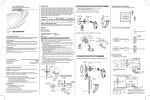
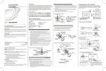
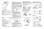
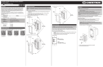
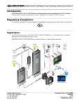
Crestron GLS-SIM Sensor Integration Module Operations & Installation Guide DESCRIPTION The GLS-SIM is a compact interface device designed to allow Crestron Green Light™ sensors to be connected directly to a Cresnet® control network. The GLS-SIM installs easily at the sensor location, mounting conveniently inside the electrical box or exposed above the ceiling. Wiring connections to the network and sensor are facilitated using miniature screw terminals. Physical Description This section provides information on the connections, controls and indicators available on your GLS-SIM. GLS-SIM Overall Dimensions The GLS-SIM is compatible with Crestron GLS-series sensors and most third party 24 Volt-powered sensors. Up to 1A @ 24VDC power is available* to support multiple sensors in parallel. The GLS-SIM actually includes two sensing inputs, each capable of sensing a contact closure, logic level, or 0-10V analog signal. When used with a Crestron IPAC or iLux™ system, setup is simplified using onboard DIP switches to select the sensor type (i.e. occupancy, photocell, partition, etc.) and operating mode (i.e. normally-open or normally-closed). *Actual load capability dependent upon the amount of available Cresnet power in the system. 1 3 2.00 in (51 mm) 4 CRESTRON HI POWER Applications 2.00 in (51 mm) The following diagram shows a GLS-SIM in a lighting system application. GLS-SIM in a Lighting System Application C C WE T NE 24 R GL SE NS OR IM OR S -S SENS T NE G Z Y 24 G 1 2 INP UT # 1 C VA 120 Further Inquiries 6M 2 -C LS 3 Check the Crestron website periodically for manual update availability and its relevance. Updates are identified as an “Addendum” in the Download column. Default Net ID 92 (mechanical setting is 00)1 Minimum 2-Series Control System Update File2, 3 Version 4.001.1012 or later Device Database Version 20.10.03 or later Crestron Database Version 20.05.20 or later Environmental Temperature Humidity Heat Dissipation 32° to104° F (0° to 40° C) 0% to 95% RH (non-condensing) 3.4 BTU/Hr WARNINGS, CAUTIONS & NOTES WARNING: To avoid fire, shock, or death; turn off power at circuit breaker or fuse and test that power is off before wiring! CAUTION: Insufficient power can lead to unpredictable results or damage to the equipment. Please use the Crestron Power Calculator to help calculate how much power is needed for the system. (www.crestron.com/calculators). NOTES: Observe the following points. • • • • • • To be installed and/or used in accordance with appropriate electrical codes and regulations. If you are unsure about any part of these instructions, consult a qualified electrician. Sensors must be mounted on a vibration free surface. All sensors must be mounted at least 6 feet (1.8 m) away from air vents. Do not mount sensors closer than 10 feet (3 m) from each other. Do not touch the inner surface of the lens. Clean outer surface with a damp cloth only. PREPARING AND CONNECTING WIRES Strip the ends of the wires approximately 1/2 inch (13 mm). Use care to avoid nicking the conductors. Twist together the ends of the wires that share a connection and tin the twisted connection. Apply solder only to the ends of the twisted wires. Avoid tinning too far up the wires or the end becomes brittle. 1 Watt (0.04 Amps @ 24 VDC) (Does not include power draw of attached devices.) Metal Metal Included mounting bracket or dual-lock fastener Dimensions Height Width Depth 2.00” (51 mm) 2.00” (51 mm) 0.86” (22 mm) Weight 2 oz (46 g) Included Accessories Mounting bracket, dual-lock fastener DESCRIPTION (1) 4-position DIP switch; Adjustable to account for various sensor types. Refer to configuration diagrams on the next page. (2) Rotary DIP Switches; Used for manually setting Cresnet ID; Set to 00 to use touch-settable ID (TSID). When using with the iLux Integrated Lighting system products (CLS-C6 series), the ID setting determines the sensor's function.2 5 SETUP (LED and button) Used to setup unit’s Net ID in conjunction with Crestron Toolbox™. (Optional) 6 NET — NET — 24 Y Z G SENSOR (1) 4-pin 5 mm detachable terminal block; Cresnet slave port, connects to Cresnet control network. 24: Power (24 Volts DC) Y: Data Z: Data G: Ground Digital Input: Rated for 0-24 Volts DC, input impedance 18.5k ohms, logic threshold 1.25 Volts DC. Digital Output: 250mA sink from maximum 24 Volts DC, catch diodes for use with “real world” loads. Maximum Power Load: 1 Amp @ 24 Volts DC3. Interface connectors for NET and SENSOR ports are provided with the unit. Refer to documentation for the CLS-C6 series products for details. Actual load capability dependent upon the amount of available Cresnet power in the system. 1. Refer to “Identity Code” in last column on this page for details. 2. The latest software versions can be obtained from the Crestron website. Refer to the NOTE following these footnotes. 3. Crestron 2-Series control systems include the AV2 and PRO2. Consult the latest Crestron Product Catalog for a complete list of 2-Series control systems. NOTE: Crestron software and any files on the website are for authorized Crestron dealers and Crestron Authorized Independent Programmers (CAIP) only. New users may be required to register to obtain access to certain areas of the site (including the FTP site). For more details, refer to “Check Network Wiring” on the next page. The Net ID of the GLS-SIM has been factory set to 92 (with a mechanical setting of 00). The Net ID of the GLS-SIM can be set using one of two methods: • Manual Setting: Set the two ID CODE switches (from 03 to FE) to match a Net ID in the SIMPL™ Windows program. • Touch-settable ID: Set the two ID CODE switches to 00 and set the Net ID using Crestron Toolbox (refer to “Establishing Communication” on the next page). This is the factory setting. For more details, refer to the Crestron Toolbox help file. ID CODE Switches When setting the Net ID, consider the following: • The Net ID of each unit must match an ID code specified in the control system program. • Each network device must have a unique Net ID. Installation The GLS-SIM can be installed inside a standard 4" electrical box or mounted above the ceiling using the included mounting bracket or the included dual-lock fastener. Refer to the following instructions and illustrations. Use the included screws to attach the included mounting bracket as shown in the following diagram. The only tool required for this step is a #1 Phillips screwdriver. Attach Mounting Bracket to GLS-SIM (Optional) Industry Compliance Dual-Technology Ceiling Mount Occupancy Sensor, 500 Sq. Ft. Dual-Technology Ceiling Mount Occupancy Sensor, 1000 Sq. Ft. Dual-Technology Ceiling Mount Occupancy Sensor, 2000 Sq. Ft. Dual-Technology Wall Mount Occupancy Sensor, 1200 Sq. Ft. Passive Infrared Ceiling Mount Occupancy Sensor, 450 Sq. Ft. Passive Infrared Ceiling Mount Occupancy Sensor, 1500 Sq. Ft. Passive Infrared Wall Mount Occupancy Sensor, 2500 Sq. Ft. Crestron Green Light Photocell, Closed-Loop Crestron Green Light Photocell, Open-Loop • For networks with 20 or more devices, use a Cresnet Hub/Repeater (e.g., DIN-HUB) to maintain signal quality. (1) 4-pin 3.5 mm detachable terminal block; Sensor input comprised of 24VDC power output and (2) Versiports (referenced to GND); adjustable 5 Volts, 2k ohms pull-up resistor per pin. Analog Input: Rated for 0-10 Volts DC, protected to 24 Volts DC maximum, input impedance 18.5k ohms. 1. 2. 3. CAUTION: Insufficient power can lead to unpredictable results or damage to the equipment. Please use the Crestron Power Calculator to help calculate how much power is needed for the system (www.crestron.com/calculators). NOTE: The ID CODE switches on the GLS-SIM are factory set to 00. This allows changing the Net ID with Crestron Toolbox™. (Optional) Indicates communication with Cresnet system. SENSOR When wiring the Cresnet network, consider the following: • Use Crestron Certified Wire. • Use Crestron power supplies for Crestron equipment. • Provide sufficient power to the system. Identity Code NET LED 7 SETUP Indicates 24 Volts DC power supplied from Cresnet control network. 4 24 1 2 G Enclosure Chassis Faceplate Mounting Available Accesssories GLS-ODT-C-500 GLS-ODT-C-1000 GLS-ODT-C-2000 GLS-ODT-W-1200 GLS-OIR-C-450 GLS-OIR-C-1500 GLS-OIR-W-2500 GLS-LCL GLS-LOL PWR LED DETAILS Power Cresnet Power Usage Operations & Installation Guide - DOC. 6768B (2022952) 10.09 Specifications subject to change without notice. ID CODE Specifications for the GLS-SIM are listed in the following table. As Crestron improves functions, adds new features and extends the capabilities of the GLS-SIM units, additional information may be made available as manual updates. These updates are solely electronic and serve as intermediary supplements prior to the release of a complete technical documentation revision. Crestron Electronics, Inc. 15 Volvo Drive Rockleigh, NJ 07647 Tel: 888.CRESTRON Fax: 201.767.7576 www.crestron.com MODE Specifications SPECIFICATION 7 Network Wiring CONNECTORS1, CONTROLS & INDICATORS C GLS-SIM Specifications Future Updates 6 NOTE: This equipment has been tested and found to comply with the limits for a Class B digital device, pursuant to part 15 of the FCC Rules. These limits are designed to provide reasonable protection against harmful interference in a residential installation. This equipment generates, uses and can radiate radio frequency energy and if not installed and used in accordance with the instructions, may cause harmful interference to radio communications. However, there is no guarantee that interference will not occur in a particular installation. If this equipment does cause harmful interference to radio or television reception, which can be determined by turning the equipment off and on, the user is encouraged to try to correct the interference by one or more of the following measures: • Reorient or relocate the receiving antenna. • Increase the separation between the equipment and receiver. • Connect the equipment into an outlet on a circuit different from that to which the receiver is connected. • Consult the dealer or an experienced radio/TV technician for help. SENSOR Connectors, Controls & Indicators CRESTRON OCCUPANCY SENSOR C R E S N E T If you cannot locate specific information or have questions after reviewing this guide, please take advantage of Crestron's award winning customer service team by calling Crestron at 1-888-CRESTRON [1-888-273-7876]. GLS -SIM — NET — 24 Y Z G 0.86 in (22 mm) P TU SE PO 5 —SETUP LIGHTING LO HI ON TR ES CR NET LO 24 1 2 G IM S-S GL You can also log onto the online help section of the Crestron website (www.crestron.com/onlinehelp) to ask questions about Crestron products. First-time users will need to establish a user account to fully benefit from all available features. 2 CAUTION: Changes or modifications not expressly approved by the manufacturer responsible for compliance could void the user’s authority to operate the equipment. This product is Listed to applicable UL Standards and requirements by Underwriters Laboratories Inc. (E174344) Suitable for use in environmental air space in accordance with Section 300-22© of the National Electrical Code (US, NFPA-70), and Sections 2-128, 12-010(3), and 12-100 of the Canadian Electrical Code, Part 1, CSA C22.1. 0.20 in (6 mm) As of the date of manufacture, the GLS-SIM has been tested and found to comply with specifications for CE marking and standards per EMC and Radiocommunications Compliance Labelling. Federal Communications Commission (FCC) Compliance Statement This device complies with part 15 of the FCC rules. Operation is subject to the following two conditions: (1) this device may not cause harmful interference and (2) this device must accept any interference received, including interference that may cause undesired operation. 2.88 in (74 mm) 2.48 in (63 mm) NOTE: Screws to secure the GLS-SIM to a surface are not included. (Continued on next page.) Installation (Continued) Sensor Digital Input. The GLS-SIM can be configured for use with sensors that use relay contacts (normally open or normally closed) or a voltage-level (active high or active low). Refer to the following tables and wiring diagrams to configure the GLS-SIM. Refer to the diagram below to use the included dual-lock fastener strip. Switch Settings for Analog Input (Read Resistance of Potentiometer) SENSOR Using Dual-Lock Fastener on the GLS-SIM (Optional) INPUT DIP CHANNEL SWITCH Switch Settings for Digital Input (Dry Contact Closure) 24 1 2 G INPUT DIP CHANNEL SWITCH SENSOR 24 1 2 G 1 Detecting a contact closure from a switch or relay 2 SETTING 1 OFF 2 OFF (Normally Open) ON (Normally Closed) 3 OFF 4 OFF (Normally Open) ON (Normally Closed) Mounting in Octagon Back Box Installed Flush to Drop Ceiling Reading resistance of a potentiometer 2 Cable Length Equation 1 OFF 2 OFF* 3 OFF 4 OFF* * Setting switches 2 or 4 to ON will invert the polarity, causing the control signal to read “100%” at 0 Volts and “0%” at 10 Volts. Digital Output. When using the GLS-SIM as a digital output, set the DIP switches as shown in the following table and wiring diagram. Switch Settings for Digital Output (Drive a Relay Coil) Octagon Back Box 4" x 1 1/2" deep Switch Settings for Digital Input (Voltage Detection) Drop Ceiling GLS-SIM 1 SETTING INPUT DIP CHANNEL SWITCH SENSOR Low-Voltage Wires 24 1 2 G #8-32 Screws (2 places) 1 24V DC Max. Detecting a voltage level SENSOR SETTING ON 2 OFF (Active Low) ON (Active High) ON 3 2 24 1 2 G 1 OFF (Active Low) ON (Active High) 4 Driving a relay coil 24V DC Max. INPUT DIP CHANNEL SWITCH 1 2 of that unit is the Cresnet power usage of the entire run. The wire gauge and the Cresnet power usage of the run should be used in the following equation to calculate the cable length value on the equation’s left side. SETTING 1 ON 2 OFF* 3 ON 4 OFF* * Setting switches 2 or 4 to ON will invert the polarity, reversing the operation based on the message from the control system. L< 40,000 RxP Where: L = Length of run (or chain) in feet R = 6 Ohms (Crestron Certified Wire: 18 AWG (0.75 MM 2 )) or 1.6 Ohms (Cresnet HP: 12 AWG (4 MM 2 )) P = Cresnet power usage of entire run (or chain) Make sure the cable length value is less than the value calculated on the right side of the equation. For example, a Cresnet run using 18 AWG Crestron Certified Wire and drawing 20 watts should not have a length of run more than 333 feet (101 meters). If Cresnet HP is used for the same run, its length could extend to 1250 feet (381 meters). NOTE: All Crestron certified Cresnet wiring must consist of two twisted pairs. One twisted pair is the +24V conductor and the GND conductor and the other twisted pair is the Y conductor and the Z conductor. Strip and Tin Wires. When daisy-chaining Cresnet units, strip the ends of the wires carefully to avoid nicking the conductors. Twist together the ends of the wires that share a pin on the network connector and tin the twisted connection. Apply solder only to the ends of the twisted wires. Avoid tinning too far up the wires or the end becomes brittle. Insert the tinned connection into the Cresnet connector and tighten the retaining screw. Repeat the procedure for the other three conductors. Add Hubs. Use of a Cresnet Hub/Repeater (CNXHUB) is advised whenever the number of Cresnet devices on a network exceeds 20 or when the combined total length of Cresnet cable exceeds 3000 feet (914 meters). Return and Warranty Policies Merchandise Returns / Repair Service Hardware Hookup Connect the Device. Make the necessary connections as called out in the illustration that follows this paragraph. Refer also to “Check Network Wiring”, which begins in the third column on this page, before attaching the NET 4-position terminal block connector. Apply power after all connections have been made. Switch Settings for Digital Input (Crestron Occupancy Sensors, e.g., GLS-ODT-C500/1000/2000) Troubleshooting SENSOR INPUT DIP CHANNEL SWITCH 24 1 2 G GLS-SIM 1 2 Red Black SETTING 1 ON 2 ON 3 ON 4 ON The following table provides corrective action for possible trouble situations. If further assistance is required, please contact a Crestron customer service representative. NOTE: Operation is ultimately determined by the control system program, and that must be considered when troubleshooting. TROUBLE GLS-ODT-C Device does not turn on (PWR LED is not lit). Sensor Blue SENSOR: SENDS POWER TO AND RECEIVES INPUT FROM SENSORS NET: TO CONTROL SYSTEM AND OTHER CRESNET DEVICES Analog Input. When using the GLS-SIM to read an analog input, set the DIP switches as shown in the following tables and wiring diagrams to configure the GLS-SIM. POSSIBLE CAUSE(S) SENSOR Other Connections. The GLS-SIM can be configured as a digital input, an analog input, or a digital output. Refer to “Configuration” below for diagrams that show how the GLS-SIM should be wired for each application. 24 1 2 G Reading a voltage from an analog source CAUTION: Incorrect wiring may damage the GLS-SIM. NOTE: The GLS-SIM can be configured as a digital input, digital output, or analog input. This setting is determined by the program running in the attached control processor. Other settings are controlled by the DIP switches, as described below. INPUT DIP CHANNEL SWITCH Use the provided Crestron power source. Verify connections. Device is not receiving sufficient power. Use the Crestron Power Calculator to help calculate how much power is needed for the system. Electrostatic discharge due to improper grounding. Check that all ground connections have been made properly. 1 2 10V DC SETTING 1 ON 2 OFF* 3 ON 4 OFF* Incorrect programming in control system. Verify DIP switch settings and sensor wiring. Check control system logic or contact Crestron for assistance. Check Network Wiring * Setting switches 2 or 4 to ON will invert the polarity, causing the control signal to read “100%” at 0 Volts and “0%” at 10 Volts. Switch Settings for Analog Input (Crestron Photocells, e.g., GLS-LCL & GLS-LOL) Use the Right Wire. In order to ensure optimum performance over the full range of your installation topology, Crestron Certified Wire and only Crestron Certified Wire may be used. Failure to do so may incur additional charges if support is required to identify performance deficiencies because of using improper wire. Calculate Power Configuration Using the DIP switches shown below, the GLS-SIM can be configured to work with various device types, as described in the following illustrations and associated tables. CAUTION: Use only Crestron power supplies for Crestron equipment. Failure to do so could cause equipment damage or void the Crestron warranty. SENSOR GLS-SIM Switch Settings DIP Switches on GLS-SIM 1234 Device does not Unit is not configured function as expected. correctly. INPUT DIP CHANNEL SWITCH ON OFF 24 1 2 G GLS-SIM SETTING 1 OFF: Enables pullup resistor ON: Disables pullup resistor 2 OFF: Normal polarity ON: Inverted polarity 3 OFF: Enables pullup resistor ON: Disables pullup resistor 4 OFF: Normal polarity ON: Inverted polarity 1 2 Red INPUT DIP CHANNEL SWITCH 1 2 GLS-LCL Black Orange SETTING 1 ON 2 OFF* 3 ON 4 OFF* * Setting switches 2 or 4 to ON will invert the polarity, causing the control signal to read “100%” at 0 Volts and “0%” at 10 Volts. 2. CORRECTIVE ACTION Device is not receiving power from a Crestron power source. Switch Settings for Analog Input (Read Voltage from Analog Source) NOTE: Depending on available Cresnet power, the GLS-SIM can pass up to 1 Amp @ 24 Volts to devices or sensors that are connected to the 24 pin of the SENSOR port. 1. PROBLEM SOLVING CAUTION: Provide sufficient power to the system. Insufficient power can lead to unpredictable results or damage to the equipment. Please use the Crestron Power Calculator to help calculate how much power is needed for the system (www.crestron.com/calculators). When calculating the length of wire for a particular Cresnet run, the wire gauge and the Cresnet power usage of each network unit to be connected must be taken into consideration. Use Crestron Certified Wire only. If Cresnet units are to be daisy-chained on the run, the Cresnet power usage of each network unit to be daisy-chained must be added together to determine the Cresnet power usage of the entire chain. If the unit is home-run from a Crestron system power supply network port, the Cresnet power usage 3. No merchandise may be returned for credit, exchange or service without prior authorization from CRESTRON. To obtain warranty service for CRESTRON products, contact an authorized CRESTRON dealer. Only authorized CRESTRON dealers may contact the factory and request an RMA (Return Merchandise Authorization) number. Enclose a note specifying the nature of the problem, name and phone number of contact person, RMA number and return address. Products may be returned for credit, exchange or service with a CRESTRON Return Merchandise Authorization (RMA) number. Authorized returns must be shipped freight prepaid to CRESTRON, 6 Volvo Drive, Rockleigh, N.J. or its authorized subsidiaries, with RMA number clearly marked on the outside of all cartons. Shipments arriving freight collect or without an RMA number shall be subject to refusal. CRESTRON reserves the right in its sole and absolute discretion to charge a 15% restocking fee plus shipping costs on any products returned with an RMA. Return freight charges following repair of items under warranty shall be paid by CRESTRON, shipping by standard ground carrier. In the event repairs are found to be non-warranty, return freight costs shall be paid by the purchaser. CRESTRON Limited Warranty CRESTRON ELECTRONICS, Inc. warrants its products to be free from manufacturing defects in materials and workmanship under normal use for a period of three (3) years from the date of purchase from CRESTRON, with the following exceptions: disk drives and any other moving or rotating mechanical parts, pan/tilt heads and power supplies are covered for a period of one (1) year; touchscreen display and overlay components are covered for 90 days; batteries and incandescent lamps are not covered. This warranty extends to products purchased directly from CRESTRON or an authorized CRESTRON dealer. Purchasers should inquire of the dealer regarding the nature and extent of the dealer's warranty, if any. CRESTRON shall not be liable to honor the terms of this warranty if the product has been used in any application other than that for which it was intended or if it has been subjected to misuse, accidental damage, modification or improper installation procedures. Furthermore, this warranty does not cover any product that has had the serial number altered, defaced or removed. This warranty shall be the sole and exclusive remedy to the original purchaser. In no event shall CRESTRON be liable for incidental or consequential damages of any kind (property or economic damages inclusive) arising from the sale or use of this equipment. CRESTRON is not liable for any claim made by a third party or made by the purchaser for a third party. CRESTRON shall, at its option, repair or replace any product found defective, without charge for parts or labor. Repaired or replaced equipment and parts supplied under this warranty shall be covered only by the unexpired portion of the warranty. Except as expressly set forth in this warranty, CRESTRON makes no other warranties, expressed or implied, nor authorizes any other party to offer any warranty, including any implied warranties of merchantability or fitness for a particular purpose. Any implied warranties that may be imposed by law are limited to the terms of this limited warranty. This warranty statement supersedes all previous warranties. Trademark Information All brand names, product names and trademarks are the sole property of their respective owners. Windows is a registered trademark of Microsoft Corporation. Windows95/98/Me/XP/Vista and WindowsNT/2000 are trademarks of Microsoft Corporation.