1
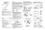
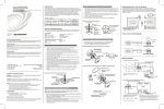
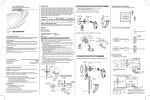
DIN-1DIM4
DIN Rail 4-Channel Dimmer
Operations & Installation Guide
Hardware Hookup
Description
The Crestron® DIN-1DIM4 is a DIN rail mounted lighting control module with four channels
of dimming. A single model supports both 120 and 220-277 V electronic and magnetic
low-voltage, incandescent, neon/cold cathode, 2-wire dimmable fluorescent, and
non-dimmable lighting loads up to 5 A per channel, 10 A total.
Additional Resources
Visit the product page on the Crestron website (www.crestron.com) or
scan the QR code to the right for additional information and the latest
firmware updates.
Make the necessary connections as shown below. Apply power after all connections have
been made. When making connections to the DIN-1DIM4, use Crestron power supplies for
Crestron equipment.
With the circuit breaker turned off, connect the wires to the terminal blocks per the
markings provided on the DIN-1DIM4.
Load Connections Example for the DIN-1DIM4
NOTE: The control system program has a setting that can prevent locally saving the
override state. If this setting is enabled, the display shows “Er” when trying to save
override states. For more information, refer to the SIMPL Windows help file.
WARNING: Prior to connecting the device, turn off power at the circuit breaker. Failure to
do so may result in serious personal injury or damage to the device. Restore power after
all connections have been made.
To save the load level as an override setting, set all of the loads to their desired levels and
then press and hold the OVR button for three seconds. The OVR LED blinks to indicate the
new override setting has been stored.
CAUTION: Connecting this device to the wrong type of load or short circuiting the load
can cause severe product damage. Each load should be tested to identify a short circuit
condition prior to wiring the load to the module.
Neutral
NOTE: Strip the ends of the wires approximately 1/4 in (6 mm). Use care to avoid nicking
the conductors. Twist together the ends of the wires that share a connection. Apply solder
only to the ends of the twisted wires. Avoid tinning too far up the wires or the end
becomes brittle.
Installation
WARNING: To avoid fire, shock, or death, turn off power at circuit breaker or fuse and
test that power is off before wiring!
CAUTION: This equipment is for indoor use only. Mount in a well-ventilated area. The
ambient temperature must be 0º to 40º C (32º to 104º F). The relative humidity must be
10% to 90% (non-condensing).
NOTE: This product should be installed and used in accordance with appropriate
electrical codes and regulations.
NOTE: This product should be installed by a qualified electrician.
NOTE: When installing in an enclosure, high-voltage devices should be grouped
separately from low-voltage devices.
Install the DIN-1DIM4
The DIN-1DIM4 installs on a DIN rail.
1. Use a flat object (e.g., a flat-head screwdriver) to pull the DIN rail release downward.
2. With the top of the unit tilted down, place the DIN-1DIM4 against the bottom of the
DIN rail.
NOTE: High-voltage connections accept 2.5 mm2 (12 AWG) wire. Wire should be stripped
to 8 mm (1/3 inch). Tighten terminal blocks to 0.5 Nm (5 in-lbs).
NOTE: The DIN-1DIM4 power feed must be protected by a 10 A (trip curve C) breaker or
equivalent.
NOTE: The DIN-1DIM4 outputs must be used to control permanently installed lighting
loads only.
NOTE: Do not mix magnetic and electronic transformers on the same dimmer output.
NOTE: Use copper wire only. For high-voltage connections, use wire rated for at least
75º C (167º F).
NOTE: Ensure the unit is properly grounded by connecting the chassis ground lug to an
earth ground (building steel).
Hardware Connections for the DIN-1DIM4
Toggle Override Mode
To enable Override mode, press the OVR button. The OVR LED flashes slowly. Override
mode can also be toggled via a remote contact closure attached to the OVERRIDE port.
Neutral
Line
Line
Ground
120/277 Volts
from Breaker
Ground
120/277 Volts
Load
Set the Net ID
The Net ID of the DIN-1DIM4 has been factory set to 89. The Net IDs of all devices in the
same system must be unique. The Net ID can be changed from the front panel of the
DIN-1DIM4 or from a personal computer via Crestron Toolbox™.
Set the Net ID using the front panel.
1. Press the SETUP button to enter Setup mode. The SETUP LED illuminates.
2. Press the left and right button under the NET ID display to change the Net ID.
3. When the desired Net ID is displayed, press the SETUP button to exit Setup mode.
The SETUP LED extinguishes.
NOTE: If an invalid Net ID is set (i.e., 00, 02, FF), “Er” will be displayed on the NET
ID display and the DIN-1DIM4 will revert to the previously set Net ID.
A small Net ID label is provided on the DIN-1DIM4 to document the unit’s Net ID in the case
where power is not available. Apply a mark over the digits that correspond to the assigned
Net ID.
NET ID Label (“3C” Shown)
3. Tilt the top of the DIN-1DIM4 toward the DIN rail until it is secure on the top edge of
the rail. Push the DIN rail release upward to lock the DIN-1DIM4 into place.
Mount DIN-1DIM4
DIN Rail
Release
Remove the DIN-1DIM4
To remove the DIN-1DIM4 from the DIN rail, use a flat object (e.g., a flat-head screwdriver)
to pull the DIN rail release and tilt the bottom of the DIN-1DIM4 away from the DIN rail.
NOTE: Certain third party DIN cabinets provide space for an informational label
between each DIN rail row. Crestron’s Engraver software (version 4.0 or later) can
generate appropriate labels for all Crestron DIN rail products.
To disable Override mode, press the OVR button again. The OVR LED extinguishes and
the outputs return to the states set by the control system program.
Reboot the DIN-1DIM4
To reboot the DIN-1DIM4, press the RESET button. The outputs will be set to the states
currently specified by the control system program. If the control system does not provide
any values, the outputs will be set to the previously set values.
Select the Operating Mode
CAUTION: Selecting an incompatible lighting load may cause damage to the
DIN-1DIM4 or the lighting load.
In the event that the DIN-1DIM4 is to be operated without a connection to a control
system, the operating mode must be set locally.
NOTE: Once a program has been downloaded to the DIN-1DIM4, the manual selection
of load types will be restricted. For example, if the program defines a channel as
NON-DIM, it cannot be set to DIM locally. Similarly, if the program defines a channel as
DIM, it cannot be set to NON-DIM locally.
Once a connection to a control system has been established, the SIMPL windows symbol
should define the unit as DIM or NON-DIM. The operating mode must still be selected
locally on the dimmer.
The operating mode is selected locally for each channel using the recessed channel mode
select buttons. Press the recessed button for the appropriate channel until the proper
operating mode is selected. Repeat this process for each channel on the dimmer. Refer to
the table that follows for information about each operating mode and the corresponding
unit display.
OPERATING MODE
Top
DIN Rail
(Not Supplied)
NOTE: If Override mode was enabled from an external device (i.e., a contact closure
connected to the OVERRIDE port), the OVR LED will flash quickly when the local OVR
button is pressed. Pressing the local OVR button has no effect when Override mode was
toggled via the remote connection.
NOTE: If override levels have not been saved, the factory default override level is 100%.
NOTE: The DIN-1DIM4 will leave Setup mode after 10 seconds of inactivity and
revert to the previously set Net ID.
NOTE: When mounting DIN rail products, it may be necessary to use a flat-head
screwdriver to pull the DIN rail release tab down while snapping the device onto
the DIN rail.
Establish Override Mode Levels
Override mode disables the control system program and sets all of the output states to the
stored override values. The state of each output can be saved as an override setting,
which can be automatically recalled when Override mode is enabled.
NET:
To Control System
and Other
Cresnet® Devices
LIVE:
Line Power Input
from AC Power Line
OVERRIDE:
From Device
Providing Override
Signal and to Other
Devices Receiving
Override Signal
NEUTRAL:
Neutral
Connection from
AC Power LIne
Ground
Operation
NOTE: Before using the DIN-1DIM4, ensure the device is using the latest firmware.
Check for the latest firmware for the DIN-1DIM4 at www.crestron.com/firmware. Firmware
is loaded onto the device using Crestron Toolbox.
DIMMED LIVE (1 - 4):
Dimmer Channel
Outputs
DIM: Channel operates as a dimmer with no
switching capabilities. The DIM LED will illuminate
when operating as a dimmer.
Operating mode should be set to DIM when
controlling dimmable fixtures.
The DIN-1DIM4 can be controlled via its front panel as well as from a control system. The
following local controls are available.
Control the Loads from the Front Panel
The lighting level of each output can be manually controlled from the front panel.
To toggle the light between off and 100% (on), tap the appropriate load button. The
corresponding LED illuminates and the output level is shown on the NET ID display (“oF” for
off, “On” for on) for two seconds after the button is released.
To ramp the lighting level up or down (until it reaches a limit), press and hold the
appropriate load button. To change the ramp direction, release the load button, and then
press and hold it again. The corresponding LED illuminates and the output level is shown on
the NET ID display as a percentage (01% to 99%) for two seconds after the button is
released.
NOTE: The control system program may change the settings if Override mode is not
enabled.
NON-DIM: Channel operates only as a switch with
no dimming capabilities. The NON-DIM LED will
illuminate when operating as a switch.
Operating mode should be set to NON-DIM when
controlling non-dimmable fixtures.
UNIT DISPLAY
TROUBLESHOOTING
The following table provides corrective action for possible trouble situations. If further
assistance is required, please contact a Crestron customer service representative.
DIN-1DIM4 Troubleshooting
TROUBLE
The device does not
function.
POSSIBLE CAUSE(S)
CORRECTIVE ACTION
The DIN-1DIM4 is
not receiving power
from the ac line or
the Crestron power
supply.
Ensure that the circuit
breaker was not tripped.
The device is not
receiving power from
a Crestron power
supply.
Use a Crestron power
supply. Verify the
connections.
The device is not
receiving sufficient
power.
Use the Crestron Power
Calculator to help
calculate how much
power is needed for the
system.
An electrostatic
discharge occurred
due to improper
grounding.
Check that all of the
ground connections
have been made
properly.
The DIN-1DIM4 is
not receiving power
from the ac line.
Ensure that the circuit
breaker was not tripped.
The unit ignores Cresnet
commands.
The unit is in Override
mode.
Take the DIN-1DIM4 out
of Override mode by
pressing the OVR button
or releasing the override
contact closure.
The LOAD LED blinks 3
times, pauses for 1
second, and then
repeats.
An overload or over
temperature situation
exists.
Reduce the load on the
channel.
The Channel 1 LED blinks
and all of the channels
turn off.
The firmware upgrade
has failed.
Cycle power on the
DIN-1DIM4.
The load flickers, flashes,
or slowly varies in light
level when running on
generator or UPS power.
There is unstable
frequency due to
generator or UPS
power.
Using Crestron Toolbox,
disable the Wilson filter.
NOTE: Disabling the
Wilson filter may leave
the dimmer susceptible
to other forms of line
noise creating flicker.
The PWR LED blinks.
As of the date of manufacture, the DIN-1DIM4 has been tested and found to comply with
specifications for CE marking.
This product is Listed to applicable UL Standards and requirements by Underwriters Laboratories Inc.
protection against harmful interference in a residential installation. This equipment generates, uses and can
radiate radio frequency energy and, if not installed and used in accordance with the instructions, may
cause harmful interference to radio communications. However, there is no guarantee that interference will
not occur in a particular installation. If this equipment does cause harmful interference to radio or television
reception, which can be determined by turning the equipment off and on, the user is encouraged to try to
correct the interference by one or more of the following measures:
•
Reorient or relocate the receiving antenna
•
Increase the separation between the equipment and receiver
Federal Communications Commission (FCC) Compliance Statement
•
This device complies with part 15 of the FCC Rules. Operation is subject to the following two
conditions:
Connect the equipment into an outlet on a circuit different from that to which the receiver is
connected
•
Consult the dealer or an experienced radio/TV technician for help
(1) This device may not cause harmful interference, and (2) this device must accept any interference
received, including interference that may cause undesired operation.
CAUTION: Changes or modifications not expressly approved by the manufacturer responsible for
compliance could void the user’s authority to operate the equipment.
NOTE: This equipment has been tested and found to comply with the limits for a Class B digital
device, pursuant to part 15 of the FCC Rules. These limits are designed to provide reasonable
The product warranty can be found at www.crestron.com/warranty.
The specific patents that cover Crestron products are listed at patents.crestron.com.
Crestron, the Crestron logo, Cresnet, and Crestron Toolbox are either trademarks or registered
trademarks of Crestron Electronics, Inc. in the United States and/or other countries. UL and the UL
logo are either trademarks or registered trademarks of Underwriters Laboratories, Inc. in the United
States and/or other countries. Other trademarks, registered trademarks, and trade names may be
used in this document to refer to either the entities claiming the marks and names or their products.
Crestron disclaims any proprietary interest in the marks and names of others. Crestron is not
responsible for errors in typography or photography.
This document was written by the Technical Publications department at Crestron.
©2015 Crestron Electronics, Inc.
Industry Canada (IC) Compliance Statement
Operation is subject to the following two conditions:
1. This device may not cause interference, and
2. This device must accept any interference, including interference that may cause undesired operation
of the device.
Crestron Electronics, Inc.
15 Volvo Drive Rockleigh, NJ 07647
Tel: 888.CRESTRON
Fax: 201.767.7576
www.crestron.com
Operations & Installation Guide - DOC. 6928B
(2026315)
04.15
Specifications subject to
change without notice.