1
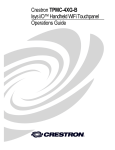
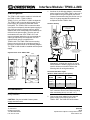
Interface Module: TPMC-L-IMC
Description
The TPMC-L-IMC interface module is included with
the TPMC-15-CH-L, TPMC-15-QM-L,
TPMC-17-CH-L, and TPMC-17-QM-L touchpanels.
The TPMC-L-IMC is used to deliver power from a
power supply to a remotely located wall mount
touchpanel. The TPMC-L-IMC converts the cable
(used by the touchpanel’s included power supply) to
two wires (see chart in following column), which
allows a wall mount touchpanel to be installed up to
60 feet from its power supply. The wire runs are
terminated on the rear of the TPMC-15/17 wall
mount touchpanel where they are converted to the
cable-type required by the touchpanel. An LED
indicates when power is supplied to the
TPMC-L-IMC. The TPMC-L-IMC has a mounting
flange to secure the unit to a mounting surface or
the rear of a rack as shown in the following diagram.
The TPMC-L-IMC should be installed near the power
supply.
1. As shown in the following diagram, connect the
power wires from the TPMC-L-IMC to the rear of
the touchpanel using the supplied connectors.
Crestron recommends using two 60 foot runs (or
less) of 14-gauge stranded wire between the
touchpanel and the TPMC-L-IMC.
Hardware Hookup
CABLE CONNECTED TO
PWR PORT ON BOTTOM OF
TOUCHPANEL
TO TOUCHPANEL:
(60 ft MAX @ 14 GAUGE x2)
OBSERVE POLARITY
(+ to + and – to –)
Physical Views of the TPMC-L-IMC
2.14 in
(5.42 cm)
PWR IN:
FROM EXTERNAL
POWER SUPPLY
2.53 in
(6.42 cm)
Alternatively, a single wire can be run over a
shorter distance. Smaller gauge wires can be
used for shorter runs as well. Refer to the
following table for wiring alternatives.
3.43 in
(8.70 cm)
Recommended Wire Lengths
(Between TPMC-L-IMC and Touchpanel)
1.05 in
(2.67 cm)
1.97 in
(5.00 cm)
2.23 in
(5.66 cm)
Installation:
CAUTION: Ensure that the power is disconnected
during installation.
CAUTION: Only the included Crestron power
supply should be used.
Crestron Electronics, Inc.
15 Volvo Drive
Rockleigh, NJ 07647
Tel: 888.CRESTRON
Fax: 201.767.7576
WIRE
GAUGE
SINGLE WIRE
(FEET)
DOUBLE WIRE
(FEET)
14 AWG
2
(2.5 mm )
30
60
16 AWG
2
(1.5 mm )
20
40
NOTE: If running a single wire, either PWR
OUT connector can be used. Observe polarity
when terminating wire (+ to + and – to –).
2. Connect the power cable from the external
power supply to the PWR IN port of the
TPMC-L-IMC. The PWR LED will illuminate.
Data Sheet – DOC. 6385
(2013189)
07.05
Specifications subject to change without notice.
www.crestron.com
Interface Module: TPMC-L-IMC
Return and Warranty Policies
Problem Solving
Merchandise Returns / Repair Service
Troubleshooting
1.
No merchandise may be returned for credit, exchange, or
service without prior authorization from CRESTRON. To
obtain warranty service for CRESTRON products, contact
the factory and request an RMA (Return Merchandise
Authorization) number. Enclose a note specifying the nature
of the problem, name and phone number of contact person,
RMA number, and return address.
2.
Products may be returned for credit, exchange, or service
with a CRESTRON Return Merchandise Authorization
(RMA) number. Authorized returns must be shipped freight
prepaid to CRESTRON, 6 Volvo Drive, Rockleigh, N.J, or its
authorized subsidiaries, with RMA number clearly marked on
the outside of all cartons. Shipments arriving freight collect
or without an RMA number shall be subject to refusal.
CRESTRON reserves the right in its sole and absolute
discretion to charge a 15% restocking fee, plus shipping
costs, on any products returned with an RMA.
3.
Return freight charges following repair of items under
warranty shall be paid by CRESTRON, shipping by standard
ground carrier. In the event repairs are found to be nonwarranty, return freight costs shall be paid by the purchaser.
The table after this paragraph provides corrective action
for possible trouble situations. If further assistance is
required, please contact a Crestron customer service
representative.
TPMC-L-IMC Troubleshooting
TROUBLE
PWR LED
does not
illuminate.
PWR LED
extinguishes
after
connecting
to
touchpanel.
POSSIBLE
CAUSE(S)
CORRECTIVE
ACTION
TPMC-L-IMC
is not
receiving
power.
Verify that the
TPMC-L-IMC is
properly connected
to the power supply.
Fuse is blown.
Remove wires that
connect to the
touchpanel. Using a
Phillips tip
screwdriver,
remove the
enclosure cover
and replace the
fuse with an 8A,
250V, 1¼” x ¼”,
Time Lag fuse.
Replace the cover
and reconnect the
wires to the
touchpanel.
Incorrect
wiring
between
TPMC-L-IMC
and
touchpanel.
Verify that the
polarity between
TPMC-L-IMC and
the touchpanel is
correct (+ to + and
– to –). Check the
wiring between the
TPMC-L-IMC and
the touchpanel for
shorts.
Further Inquiries
If you cannot locate specific information or have questions
after reviewing this sheet, please take advantage of
Crestron's award winning customer service team by calling
the Crestron corporate headquarters at
1-888-CRESTRON [1-888-273-7876]. For assistance in
your local time zone, refer to the Crestron website
(www.crestron.com) for a listing of Crestron worldwide
offices.
You can also log onto the online help section of the
Crestron website to ask questions about Crestron
products. First-time users will need to establish a user
account to fully benefit from all available features.
As of the date of manufacture, the TPMC-L-IMC has been
tested and found to comply with specifications for CE
marking and standards per EMC and
Radiocommunications Compliance Labelling.
CRESTRON Limited Warranty
CRESTRON ELECTRONICS, Inc. warrants its products to be free
from manufacturing defects in materials and workmanship under
normal use for a period of three (3) years from the date of
purchase from CRESTRON, with the following exceptions: disk
drives and any other moving or rotating mechanical parts, pan/tilt
heads and power supplies are covered for a period of one (1)
year; touchscreen display and overlay components are covered
for 90 days; batteries and incandescent lamps are not covered.
This warranty extends to products purchased directly from
CRESTRON or an authorized CRESTRON dealer. Purchasers
should inquire of the dealer regarding the nature and extent of the
dealer's warranty, if any.
CRESTRON shall not be liable to honor the terms of this warranty
if the product has been used in any application other than that for
which it was intended, or if it has been subjected to misuse,
accidental damage, modification, or improper installation
procedures. Furthermore, this warranty does not cover any
product that has had the serial number altered, defaced, or
removed.
This warranty shall be the sole and exclusive remedy to the
original purchaser. In no event shall CRESTRON be liable for
incidental or consequential damages of any kind (property or
economic damages inclusive) arising from the sale or use of this
equipment. CRESTRON is not liable for any claim made by a third
party or made by the purchaser for a third party.
CRESTRON shall, at its option, repair or replace any product
found defective, without charge for parts or labor. Repaired or
replaced equipment and parts supplied under this warranty shall
be covered only by the unexpired portion of the warranty.
Except as expressly set forth in this warranty, CRESTRON makes
no other warranties, expressed or implied, nor authorizes any
other party to offer any warranty, including any implied warranties
of merchantability or fitness for a particular purpose. Any implied
warranties that may be imposed by law are limited to the terms of
this limited warranty. This warranty statement supercedes all
previous warranties.
Trademark Information
All brand names, product names, and trademarks are the sole property of their
respective owners. Windows is a registered trademark of Microsoft Corporation.
Windows95/98/Me/XP and WindowsNT/2000 are trademarks of Microsoft Corporation.
2 • Interface Module: TPMC-L-IMC
Data Sheet – DOC. 6385