1
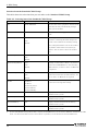
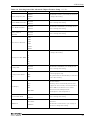
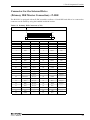
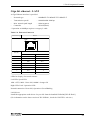
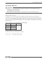
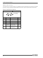
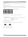
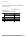
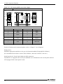
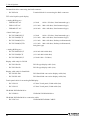
5. Each Component Function
Table 5.12. Function of Each Register < 2 / 4 >
I/O address
03FAH
Description
IIR : Interrupt Identification Register
D7
D6
D5
D4
D3
D2
0
0
0
0
D1
D0
0
Interrupt details
bit2 bit1 bit0 Priority
03FBH
1: Do not generate interrupts
0: Generate interrupts
Description
Interrupts are not generated.
0
0
1
1
1
0
1 (high)
Generated by overrun, parity, framing error or break
interrupt.
Cleared when the line status register is read.
1
0
0
2
Generated when the receive buffer register is ready.
Cleared when the receiving buffer is read.
0
1
0
3
Generated when the transmitter holding register is
empty. Cleared when the IIR is read or when
transmitted data is written to THR.
0
0
0
4 (low)
Modem status interrupt is generated.
(CTS, DSR, RI, CD)
Cleared when the modem status register is read.
LCR : Line Contror Regester
D7
D6
D5
D4
D1 D0 Bit table
D3
D2
D1
D0
0
0
5
0
1
6
1
0
7
1
1
8
0 : 1 STOP bit
1 : 1.5 STOP bits at 5-bit length
2 STOP bits at 6-, 7-, or 8-bit length
0 : Disable parity
1 : Enable parity
0 : Odd parity
1 : Even parity
0 : Disable stick parity
1 : Enable stick parity
0 : Break signal off
1 : Send break signal
DLAB (Divisor Latch Access Bit)
In order to access the divisor latch register, you need to set the bit
to 1. To access another register, set the bit to 0.
66
User’s Manual