1
IPC Series
BOX-PC
for IPC-BX/M360(PCI)C
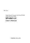
User’s Manual
CONTEC CO.,LTD.
Copyright
Copyright 2005 CONTEC CO., LTD. ALL RIGHTS RESERVED.
No part of this document may be copied or reproduced in any form by any means without prior written
consent of CONTEC CO., LTD.
CONTEC CO., LTD. makes no commitment to update or keep current the information contained in this
document.
The information in this document is subject to change without notice.
All relevant issues have been considered in the preparation of this document. Should you notice an
omission or any questionable item in this document, please feel free to notify CONTEC CO., LTD.
Regardless of the foregoing statement, CONTEC assumes no responsibility for any errors that may
appear in this document or for results obtained by the user as a result of using this product.
Trademarks
Intel and Celeron are registered trademarks of Intel Corporation. MS, Microsoft and Windows are
trademarks of Microsoft Corporation. Other brand and product names are trademarks of their respective
holder.
User’s Manual
i
Table of Contents
Copyright ............................................................................................................................................. i
Trademarks .......................................................................................................................................... i
Table of Contents................................................................................................................................ ii
1.
INTRODUCTION
1
Features ........................................................................................................................................ 1
Supported OS ............................................................................................................................... 1
Customer Support ............................................................................................................................... 2
Web Site....................................................................................................................................... 2
Limited One-Year Warranty............................................................................................................... 2
How to Obtain Service........................................................................................................................ 2
Liability............................................................................................................................................... 2
Safety Precautions .............................................................................................................................. 3
Safety Information ....................................................................................................................... 3
Handling Precautions ................................................................................................................... 3
FCC PART 15 Class A Notice .................................................................................................... 4
2.
OVERVIEW
5
Specifications...................................................................................................................................... 5
System Configuration ......................................................................................................................... 8
Physical Dimensions........................................................................................................................... 9
3.
HARDWARE SETUP
11
Before Using the BOX-PC for the First Time.................................................................................. 11
Hardware Setup................................................................................................................................. 12
Removing the Left-side Cover and HDD Bracket .................................................................... 12
Locations and Settings of Internal Connectors and Jumpers .................................................... 13
Power connection....................................................................................................................... 14
Installation method .................................................................................................................... 15
Installation Requirements .......................................................................................................... 17
4.
BIOS SETUP
19
BIOS Setup ....................................................................................................................................... 19
Starting the Setup Screen........................................................................................................... 19
Main Menu ................................................................................................................................. 22
Standard CMOS Setup ............................................................................................................... 23
Advanced BIOS Features Setup ................................................................................................ 25
Advanced Chipset Features Setup ............................................................................................. 29
Integrated Peripherals ................................................................................................................ 35
ii
User’s Manual
Power Management Setup ......................................................................................................... 39
PnP/PCI Configuration Setup .................................................................................................... 45
PC Health Status ........................................................................................................................ 47
Frequency/Voltage Control ....................................................................................................... 48
Load Fail-Safe Defaults............................................................................................................. 48
Load Optimized Defaults........................................................................................................... 48
Supervisor/User Password Setting ............................................................................................ 49
Save & Exit Setup...................................................................................................................... 50
Exit Without Saving .................................................................................................................. 50
POST Messages ................................................................................................................................ 51
POST Beep ....................................................................................................................................... 51
Error Messages ................................................................................................................................. 52
5.
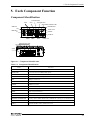
EACH COMPONENT FUNCTION
55
Component Identification .......................................................................................................... 55
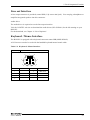
Line out Interface....................................................................................................................... 57
Keyboard / Mouse Interface ...................................................................................................... 57
Serial Port Interface ................................................................................................................... 58
USB Ports .................................................................................................................................. 64
Ethernet ...................................................................................................................................... 65
PC Card Slots............................................................................................................................. 66
DVI Connector........................................................................................................................... 67
RAS Functions ........................................................................................................................... 71
Watchdog Timer ........................................................................................................................ 72
General-purpose I/O .................................................................................................................. 76
RS-422/485 ................................................................................................................................ 78
IDE Interface ............................................................................................................................. 80
6.
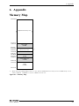
APPENDIX
83
Memory Map .................................................................................................................................... 83
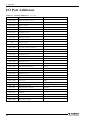
I/O Port Addresses............................................................................................................................ 84
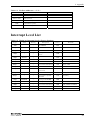
Interrupt Level List........................................................................................................................... 85
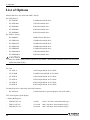
List of Options .................................................................................................................................. 86
User’s Manual
iii
iv
User’s Manual
1. Introduction
1. Introduction
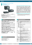
The IPC-BX/M360(PCI)C is an IBM PC/AT compatible, box computer designed for industrial use based
on the Ultra Low Voltage Intel(R) Celeron(R) Processor 400MHz, to operate as a completely
nature-cooled (fanless) system.
The IPC-BX/M360(PCI)C is smaller in size than the IPC-BX/M400(PC)H while providing assorted
interfaces such as USB 2.0, 100BASE-TX, and RS-232C. It can be a compact platform based on an OS
for general-purpose PCs. As this series incorporates handpicked components such as the embedded types
of CPU and chipset, it excels in environmental resistance and remains in stable supply for an extended
period of time. You can therefore use the box computer under severe operating conditions such as FA with
ease.
For the components of this package, refer to the bundled product guide. If you discover damaged or
missing items, contact your retailer.
Features
-
Equipped with the latest Ultra Low Voltage Intel(R) Celeron(R) Processor 400MHz (FSB 100MHz)
CPU
Very small size (system unit: 146 (W) x 157 (D) x 64 (H))
Fan-less operation achieved by natural air-cooling
High reliability and completely silent running (when fitted with the PC-SDD V series silicon disk
from CONTEC)
Long, reliable supply (The CPU and chip set are embedded versions.)
Adopting the slot-in mounted HDD implements easy maintenance and replacement easy.
Equipped with a DVI video output connector (VGA adapter bundled)
Capable of starting up, even with the battery dead, using CMOS data retained by EEPROM
Equipped with PC Card Slot, CF Card Slot (dedicated to memory card; bootable), 100BASE-TX x 2
ports and USB 2.0 x 4 ports
Equipped with a secondary-IDE connector to allow an optional external CD-ROM drive to be
connected
Equipped with AC97 compliant audio features
Supported OS
-
Windows 2000 Professional
Windows XP Embedded
Windows XP Professional
*
The Windows 2000 Profession and Windows XP Embedded models have the recovery CD-ROM
bundled for restoring the OS environment to the default state.
*
The Windows XP Profession model has the OS install CD-ROM (DSP version) and driver & utility
set CD-ROM [IPC-SLIB-01] bundled. To restore the OS environment to the default, install the OS
and then individual drivers.
User’s Manual
1
1. Introduction
Customer Support
CONTEC provides the following support services for you to use CONTEC products more efficiently and
comfortably.
Web Site
Japanese
English
Chinese
http://www.contec.co.jp/
http://www.contec.com/
http://www.contec.com.cn/
Latest product information
CONTEC provides up-to-date information on products.
CONTEC also provides product manuals and various technical documents in the PDF.
Free download
You can download updated driver software and differential files as well as sample programs available in
several languages.
Note! For product information
Contact your retailer if you have any technical question about a CONTEC product or need its price,
delivery time, or estimate information.
Limited One-Year Warranty
CONTEC Products are warranted by CONTEC CO., LTD. to be free from defects in material and
workmanship for up to one year from the date of purchase by the original purchaser.
Repair will be free of charge only when this device is returned freight prepaid with a copy of the original
invoice and a Return Merchandise Authorization to the distributor or the CONTEC group office, from
which it was purchased.
This warranty is not applicable for scratches or normal wear, but only for the electronic circuitry and
original products. The warranty is not applicable if the device has been tampered with or damaged
through abuse, mistreatment, neglect, or unreasonable use, or if the original invoice is not included, in
which case repairs will be considered beyond the warranty policy.
How to Obtain Service
For replacement or repair, return the device freight prepaid, with a copy of the original invoice. Please
obtain a Return Merchandise Authorization number (RMA) from the CONTEC group office where you
purchased before returning any product.
* No product will be accepted by CONTEC group without the RMA number.
Liability
The obligation of the warrantor is solely to repair or replace the product. In no event will the warrantor
be liable for any incidental or consequential damages due to such defect or consequences that arise from
inexperienced usage, misuse, or malfunction of this device.
2
User’s Manual
1. Introduction
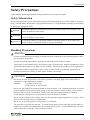
Safety Precautions
Understand the following definitions and precautions to use the product safely.
Safety Information
This document provides safety information using the following symbols to prevent accidents resulting in
injury or death and the destruction of equipment and resources. Understand the meanings of these labels
to operate the equipment safely.
DANGER
DANGER indicates an imminently hazardous situation which, if not avoided, will
result in death or serious injury.
WARNING
WARNING indicates a potentially hazardous situation which, if not avoided, could
result in death or serious injury.
CAUTION
CAUTION indicates a potentially hazardous situation which, if not avoided, may
result in minor or moderate injury or in property damage.
Handling Precautions
WARNING
-
Always check that the power supply is turned off before connecting or disconnecting power cables.
-
Do not modify the product.
-
Always turn off the power before inserting or removing circuit boards or cables.
-
This product is not intended for use in aerospace, space, nuclear power, medical equipment, or other
applications that require a very high level of reliability. Do not use the product in such applications.
-
If using this product in applications where safety is critical such as in railways, automotive, or
disaster prevention or security systems, please contact your retailer.
-
Do not use or store the product in a location exposed to extremely high or low temperature or
susceptible to rapid temperature changes.
Example:
- Exposure to direct sun
- In the vicinity of a heat source
Do not use the product in extremely humid or dusty locations. It is extremely dangerous to use the
product with its interior penetrated by water or any other fluid or conductive dust. If the product
must be used in such an environment, install it on a dust-proof control panel, for example.
Avoid using or storing the device in locations subject to shock or vibration.
Do not use the product in the vicinity of devices that generate strong magnetic force or noise. Such
devices will cause this device to malfunction.
Do not use or store the product in the presence of chemicals.
The heat sink on top may become hot. To avoid being burned, do not touch that section while the
product is in operation or immediately after turning off the power. Avoid installation in a location
where people may come into contact with that section.
CAUTION
-
-
User’s Manual
3
1. Introduction
-
To clean the BOX-PC, wipe it gently with a soft cloth dampened with either water or mild detergent.
Do not use chemicals or a volatile solvent, such as benzene or thinner, to prevent pealing or
discoloration of the paint.
- 2.5 inches hard disk drive (HDD) of our company has not guaranteed use by continuation and
continuation power for 24 hours. When it is used by continuation operation and continuation power,
a life fails extremely. In the case of a 24 hours operation system, use of our company silicon disk
drive (SDD) is recommended.
- Hard disks have a limited life span. Please perform systematic backup and maintenance.
- CONTEC does not provide any guarantee for the integrity of data on hard disks.
- To prevent corruption of files, always shutdown the OS before turning off the BOX-PC.
- Be sure to unplug the power cable from a wall outlet before plugging or unplugging a PCMCIA card,
CF card, or any connector.
- CONTEC reserves the right to refuse to service a product modified by the user.
- In the event of failure or abnormality (foul smells or excessive heat generation), unplug the power
cord immediately and contact your retailer.
- To connect with peripherals, use a grounded, shielded cable.
- Component Life:
(1) Battery--- The internal calendar clock and CMOS RAM are backed by a Lithium primary
battery. The backup time at a temperature of 25°C with the power disconnected is
10 years or more.
* Replacement of expendables is handled as a repair (there will be a charge).
- Connection USB apparatus
There is USB apparatus by which current flows conversely to BOXPC through a connection cable at
the time of power supply off of BOXPC. When such apparatus is connected, since 5V power supply
does not turn off completely, BOXPC may be unable to be started. In such a case, please remove
USB apparatus and connect again after a power supply injection. However, please connect again
before performing apparatus detection, when using USB apparatus as a boot device.
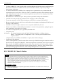
FCC PART 15 Class A Notice
NOTE
This equipment has been tested and found to comply with the limits for a Class A digital device,
pursuant to part 15 of the FCC Rules. These limits are designed to provide reasonable protection
against harmful interference when the equipment is operated in commercial environment.
This equipment generates, uses, and can radiate radio frequency energy and, if not installed and
used in accordance with the instruction manual, may cause harmful interference to radio
communications. Operation of this equipment in a residential area is likely to cause harmful
interference at his own expense.
WARNING TO USER
Change or modifications not expressly approved the manufacturer can void the user's authority to
operate this equipment.
4
User’s Manual
2. Overview
2. Overview
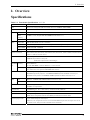
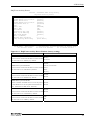
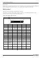
Specifications
Table 2.1. Functional Specifications < 1 / 2 >
Model
CPU
Ultra Low Voltage Intel(R) Celeron(R) Processor 400MHz, FSB100MHz
Chip set
Memory
IPC-BX/M360(PCI)C
VIA CLE266(VT8623+VT8235)
L2 Cache
256KB
Main
512MB *1 (3.3V 200pin DDR SO-DIMM PC2100 Socket x 1)
memory
Video
BIOS ROM
128KB E0000H - FFFFFH (Award)
Controller
VIA VT8623 (Built into the controller)
Video RAM
Main memory shared (Default 32MB, Up to 64 MB configurable by BIOS
Video BIOS
64KB (C0000H - CFFFFF)
Display I/F
DVI-I 29pin *2
System resolution
640 x 480(16,770,000 colors), 800 x 600(16,770,000 colors), 1,024 x 768(16,770,000 colors),
1,280 x 1,024(16,770,000 colors)
Audio
AC97 compliant
LINE OUT: φ3.5 Stereo mini jack
Full-scale output level 1.0Vrms(Typ.)
IDE HDD Primary
I/F
Ultra DMA/133
2.5 inch IDE HDD or silicon disk drive: 1 internal unit
Secondary
Equipped with a dedicated 36pin, half-pitch connector
(for connection of an optional CD-ROM) (left surface)
Serial I/F
RS-232C (general-purpose): 2ch (SERIAL PORT1, 2) 9pin D-SUB connector
RS-422/485 (general-purpose): 1ch (SERIAL PORT1) [inside the RAS connector] *3
RS-232C (touch panel): 1ch (SERIAL PORT2) [inside the DVI connector] *4 *5
LAN
I/F
Ethernet 100BASE-TX/10BASE-T RJ-45 connector: 2ch
Controller
Realtek RT8139DL x 2
PC Card Slot
PCMCIA Type I or II x 1 (Startup from ATA card not allowed)
CardBus correspondence
CF Card Slot
CF CARD Type I, II x 1 (For memory card) (Secondary IDE) *6
USB I/F
4ch (USB 2.0 specification)
Keyboard I/F
Corresponding to PS/2 keyboard (6pin MINI DIN connector)
(PS/2 mouse acceptable with the bundled keyboard/mouse branch cable)
General-purpose I/O
3 opto-isolated inputs and outputs
(However, one output also serves as an external WDT output and one input also serves
as remote reset. They become available when switched.)
User’s Manual
5
2. Overview
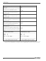
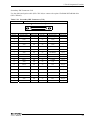
Table 2.1. Functional Specifications < 2 / 2 >
Model
RAS function
IPC-BX/M360(PCI)C
WDT: 1sec - 255sec (RESET or external output is allowed at time expiration)
Remote reset: External input signal
Expansion board slot
RTC/CMOS
None
Lithium backup battery life: 10 years or more
The real-time clock is accurate within ±2 minutes (at 25°C) per month.
DC Power Input supply voltage 10 - 12VDC (However, change is less then ±5% of power supply voltage)
supply
Current consumption 12V 2.5A (Max.)
Current consumption 12V 0.27A(Max.)
(At shutdown) *7
Physical dimensions (mm)
146(W) x 157(D) x 64(H) (No protrusion)
Weight
About 1.5kg
Supported OS
Windows 2000 Professional, Windows XP Embedded, Windows XP Professional
*1
512MB memory module is plugged. No more memory can be added.
*2
The interface can connect the PC to a CONTEC Panel Link input type display (using an optional cable) or an
*3
The SERIAL1 connector (RS-232C) and RS-422/485 are mutually exclusive. (RS-232C is used by factory default.)
*4
The interface is used for the CONTEC Panel Link or touch panel type display.
ordinary analog RGB input display (using the bundled DVI-analog RGB adapter).
*5
The SERIAL2 connector (RS-232C) and touch panel function are mutually exclusive. (Touch panel function is used
by factory default.)
*6
When starting Windows from CF card, CF card different from a general marketing article is required.
( Our company option CF card can start Windows. However, the capacity of CF card should choose the thing in
which Windows installation is possible.)
Moreover, about operation of CF card, it is checking with our company option CF card. Operation of all the cards of
general marketing is not secured.
*7
6
At ATX mode.
User’s Manual
2. Overview
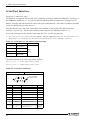
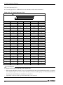
Table 2.2. Installation Environment Requirements
Parameter
Requirement description
0 - 45°C (SDD in use)
Operating temperature
5 - 40°C (HDD in use)
Storage temperature
-10 - 60°C
Operating humidity
10 - 90%RH(No condensation)
Floating dust particles
Not to be excessive
Corrosive gases
None
Line-noise
Static electricity
Contact discharge/4kV (IEC1000-4-2Level 2, EN61000-4-2Level 2)
resistance
resistance
Atmospheric discharge/8kV (IEC1000-4-2Level 3, EN61000-4-2Level 3)
When the HDD is in
Vibration
resistance *8
operation.
25 min. each in x, y, and z directions
(JIS C0040-compliant, IEC68-2-6-compliant)
When the
10 - 57Hz/semi-amplitude 0.15mm 57 - 150Hz/2.0G
HDD is not in operation.
40 min. each in x, y, and z directions
(when deenergized)
(JIS C0040-compliant, IEC68-2-6-compliant)
10G, half-sine shock for 11 ms in x, y, and z directions
Impact resistance *7 *8
(JIS C0041-compliant, IEC68-2-27-compliant)
Grounding
*7
10 - 50Hz/0.5G
Class D grounding (previous class 3 grounding)
Not guaranteed in all environments while tried and tested for conformance under relevant test conditions.
Not guaranteed for resistance to resonance which can occur in the vicinity of the natural frequency of the system
unit.
*8
When the HDD is not in use.
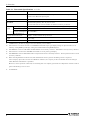
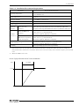
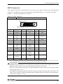
Power Up Specification for DC Powered Models
Volt
1 to 30mS
11.4V
Time
User’s Manual
7
2. Overview
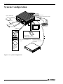
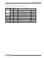
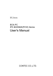
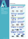
System Configuration
SERIAL port
USB
LINE OUT
6pin mini DIN cable
(Keyboard mouse distribution cable)
Option CD-ROM
RST Switch
CF Card
Mouse
LAN
HDD
Display
Keyboard
USB2.0/1.1
FD drive
PC Card Slot
PCMCIA Type I or II x 1
Printer
Power unit IPC-POAW/10-01
(Option)
Using the bundled
cable of IPC-POAW/10-01
to connect.
USB device
such as the
CD-ROM
drive
Figure 2.1. System Configuration
8
User’s Manual
2. Overview
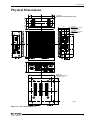
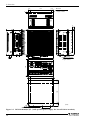
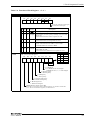
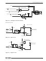
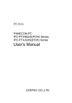
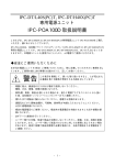
Physical Dimensions
(13)
(13)
M4 TAP
(Maximum tapping length: 5mm)
(18)
28
(18)
120
64
28
(18)
M4 TAP
(Maximum tapping
length: 5mm)
M3 TAP
(Maximum tapping
length: 5mm)
(6)
49.4
157
79.2
(18)
22.4
146
USB
DVI
64
SERIAL1
PCMCIA
PWR
ACCESS
KB
SPK
RST
SPD
RAS
SERIAL2
ACT
LNK ACT
LAN2
LNK
LAN1
DC-IN
116
(15)
M4 TAP
(Maximum tapping
length: 5mm)
(18.5)
120
(18.5)
(15)
FG V- V+
[mm]
Figure 2.2. IPC-BX/M360(PCI)C
User’s Manual
9
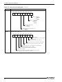
2. Overview
(13)
(13)
9
120
M4 TAP
(Maximum tapping
length: 5mm)
(6)
157
9
M4 TAP
(Maximum tapping
length: 5mm)
146
SERIAL1
USB
DVI
PCMCIA
PWR
ACCESS
KB
SPK
RST
SPD
102
RAS
SERIAL2
ACT
LNK ACT
LAN2
LNK
LAN1
DC-IN
N
FG V- V+
10VDC-OUT
L
FG V- V+
134
(6)
(18.5)
120
(18.5)
(6)
[mm]
M4 TAP
(Maximum tappinglength: 5mm)
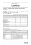
Figure 2.3. IPC-BX/M360(PCI)C (with optional power supply IPC-POAW/10-01 installed)
10
User’s Manual
3. Hardware Setup
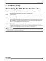
3. Hardware Setup
Before Using the BOX-PC for the First Time
Follow the next steps to set up the BOX-PC:
STEP1
Install the hard disk and set jumper switches.
By referring to the information in this chapter, set the BOX-PC.
STEP2
Connect cables.
Connect necessary external devices, such as a printer and a CRT, to the BOX-PC using
appropriate cables.
STEP3
Turn on the power.
After verifying that you have correctly followed steps 1 and 2, turn on the power. If you
feel something is wrong after turning on the power, turn off the power immediately and
check to see if the BOX-PC has been set up correctly.
STEP4
Set up BIOS.
By referring to Chapter 4, set up BIOS. This setup requires a keyboard and a display.
* Before using the BOX-PC, be sure to execute "Load Optimized Defaults" to initialize the
BIOS settings to their default values. (See Chapter 4, "Main Menu.")
CAUTION
If your BOX-PC is a Windows preinstalled model, be sure to connect the keyboard and mouse to it
before turning the power on for the first time.
User’s Manual
11
3. Hardware Setup
Hardware Setup
Removing the Left-side Cover and HDD Bracket
-
Before you start, be sure that the power is turned off.
Remove only those screws that are explained. Do not move any other screw.
(1) Remove the screws from the left-side cover and open the cover.
(2) Remove the hard disk bracket.
To remove the hard disk (silicon disk) unit, open the left-side
cover, hook the lower end of the cover on the chassis to lever the
unit out toward you.
Figure 3.1. Removing the HDD bracket
(3) Connect the hard disk (silicon disk) to the HDD bracket.
(4) Insert the hard disk unit (silicon disk drive) as illustrated below and attach the left-side cover.
HDD or SDD
Attachment position adjustment hole *1
Figure 3.2. Removing and attaching the left-side cover, HDD bracket
*1 A connector attachment position change with HDD(SDD). Please adjust HDD(SDD) attachment
position adjustment hole after checking a side cover attachment.
CAUTION
Do not plug the HDD (SDD) with its pins bent.
Doing so may break the pins.
12
User’s Manual
3. Hardware Setup
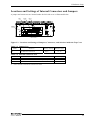
Locations and Settings of Internal Connectors and Jumpers
A jumper and connectors are located under the left-side cover as illustrated below.
JP1
CN5
CN1
HDD
< Left-side >
Figure 3.3. Locations and Settings of Jumpers, Connectors, and Switches inside the Top Cover
Table 3.1. Jumper List
Name
JP1
Function
Sets RS-485 termination
Factory setting
Open
Reference page
78, 79
Table 3.2. Internal Connector List
Name
Function
Reference page
CN1
CD-ROM Connection Connector (36 pin half pitch)
81
CN5
CF Card Connector *1
82
*1
Insert the CF card with the bottom face down.
User’s Manual
13
3. Hardware Setup
Power connection
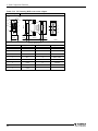
Table 3.3. Power Connector
Connector
type
DFK-MC1,5/3-GF-3,81
DC input connector
Type
(Made by PHONIX
Pin No.
Signal name
1
FG
2
GND
3
VCC
CONTACT)
1 2 3
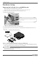
Connect the power unit IPC-POAW/10-01(option) for the IPC-BX/M360(PCI)C.
(1) Check that the power unit’s SW is turned to be OFF.
(2) Connect the DC cable of power unit to the power connector on the computer itself.
(3) Fasten the DC cable with its built-in screws on both sides.
IPC-BX/M360(PCI)C
Attached screws
(IPC-POAW/10-01's accessory)
DC Cable
(IPC-POAW/10-01's
accessory)
Attached fittings
(IPC-POAW/10-01's accessory)
IPC-POAW/10-01
Figure 3.4. Connecting the IPC-BX/M360(PCI)C to the IPC-POAW/10-01(option)
14
User’s Manual
3. Hardware Setup
An external power cable connector [MC1,5/3STF-3,81] is bundled. You can use this connector to
connect a 10-V to 12-V external power supply. (A power supply of at least 30W is required to operate
the IPC-BX/M360(PCI)C normally.)
28 to 16AWG
MC1,5/3STF-3,81 (bundled)
Figure 3.5. Connection with power cable connector in use
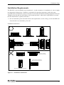
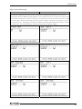
Installation method
The system unit can be installed in one of the orientations in (1) to (3) below. (Using the bundled system
unit brackets)
190
(1)
170
16
120
10
R2.5
R5.5
10.5
5
(Connector side)
146
USB
DVI
64
SERIAL1
PCMCIA
PWR
ACCESS
KB
SPK
RST
SPD
RAS
SERIAL2
ACT
LNK ACT
LAN2
LNK
LAN1
2.3
DC-IN
FG V- V+
[mm]
Figure 3.6. Installation method < 1 / 3 >
User’s Manual
15
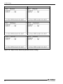
3. Hardware Setup
10
(2)
146
120
5
USB
DVI
102
82
SERIAL1
PCMCIA
PWR
KB
AC CESS
SPK
RST
SPD
RAS
SERIAL2
LNK ACT
ACT
LAN2
LNK
LAN1
DC-IN
FG V- V+
16
R2.5
R5.5
[mm]
5
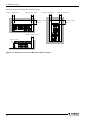
Figure 3.6. Installation method < 2 / 3 >
R2.5
R5.5
5
10.5
16
120
(3)
(Connector side)
82
102
10
[mm]
Figure 3.6. Installation method < 3 / 3 >
16
User’s Manual
3. Hardware Setup
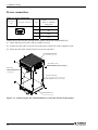
Installation Requirements
The BOX-PC can be installed in any orientation Ο. Avoid orientation x’s installation *1 since it might
not adequately dissipate heat. Similarly, to maintain the operating temperature within the range
specified in the specifications, ensure a clearance between the unit and surrounding equipment of at least
100mm for the top and rear and 50mm for the bottom and sides. (Meet these requirements even with
the IPC-POAW/10-01 (option) connected.)
*1 Do not install the system unit with the heat sink upside down, on the ceiling, or with the HDD unit
slot (left-side cover) blocked by the wall.
Installation Orientation
SERIAL1
SERIAL2
ACT
LAN2
USB
LNK ACT
LAN1
LNK
PCMCIA
KB
SPK
A CC E SS
DVI
RAS
USB
DVI
PWR
SERIAL1
SPD
P WR
AC C ESS
DC -IN
PCMCIA
RST
SPD
LNK ACT
LNK
DC-IN
RST
LAN1
SPK
LAN2
KB
ACT
FG V- V+
RAS
SERIAL2
FG V- V+
SERIAL1
SERIAL2
ACT
LAN2
USB
LNK ACT
SERIAL1
USB
DVI
L AN1
LNK
(Connector side)
PCMCIA
PCMCI A
P WR
KB
AC CE S S
SPK
RST
SPD
RAS
ACT
A C CE S S
RAS
DVI
PWR
SERIAL2
LAN2
LNK AC T
LAN1
LNK
DC-IN
FG V-
V+
SPD
DC-IN
KB
SPK
D C -I N
LAN2
ACT
F G V- V+
DC -I N
LAN1
LNK AC T
LNK
SERIAL2
LAN2
ACT
SERIAL1
PWR
USB
A CC ES S
FG V - V +
LAN1
LNK ACT
LNK
RAS
PCMCIA
RST
V+
SERIAL2
FG V-
On the ceiling
RAS
SP D
DVI
RST
KB
SPK
PCMCIA
SERIAL1
PWR
A CC ES S
DVI
USB
RST
S PD
KB
SPK
F G V- V+
RST
Left-side face blocked
A CC ESS
RAS
PW R
DVI
SP D
D C -IN
KB
SPK
Upside down
USB
DVI
KB
SPK
LNK
PCMCIA
SERIAL1
PWR
A CC ESS
RST
S PD
RAS
ACT
LAN2
LNK ACT
LAN1
LNK
D C -I N
FG V - V +
SERIAL2
SERIAL1
ACT
LAN2
USB
LNK AC T
LAN1
PCMCIA
SERIAL2
Top face positioned vertically
Figure 3.7. Installation Orientation
User’s Manual
17
3. Hardware Setup
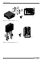
Distances between the BOX-PC and Its Vicinity
50mm or more (side)
50mm or more (side)
50mm or more (side)
50mm or more (side)
100mm or more
(above)
100mm or more
(above)
DVI
PCMCIA
PWR
KB
ACCESS
SPD
SPK
RST
ACT
ACT
LN K ACT
LNK
LAN1
FG V- V+
USB
DC-IN
LNK ACT
LAN2
LAN2
RAS
SERIAL2
SERIAL1
USB
SERIAL2
SERIAL1
LAN1
LNK
PCMCIA
ACCESS
DVI
PWR
RAS
50mm or more (back)
SPD
DC-IN
KB
SPK
RST
FG V- V+
Connector side
Figure 3.8. Distances between the BOX-PC and Its Vicinity
18
User’s Manual
4. BIOS Setup
4. BIOS Setup
BIOS Setup
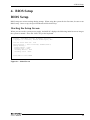
BIOS setup sets various settings during startup. When using the system for the first time, be sure to run
BIOS setup. Once set up, the specified details will be backed up.
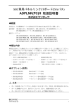
Starting the Setup Screen
When you turn on the system power supply, the BOX-PC displays the following initial screen as long as
the system is normal. Press the <DEL> key at the keyboard.
Phoenix - AwordBIOS v6.00PG, An Energy Star Ally
Copyright (C) 1984-2003, Phoenix Technologies, LTD
IPC-360 series BIOS ver. x.xx
Main processor : Intel Celeron(R) 400MHz(100x4.0)
Memory Testing :
Primary Master : None
Primary Slave : None
Secondary Master : None
Secondary Slave : None
Press DEL to enter SETUP
Figure 4.1. Initial Screen
User’s Manual
19
4. BIOS Setup
Using Setup
In general, you use the arrow keys to highlight items, press <Enter> to select, use the <PageUp> and
<PageDown> keys to change entries, press <F1> for help and press <Esc> to quit.
Table 4.1. Using Setup program
Key
Function
Up Arrow
Move to the previous item
Down Arrow
Move to the next item
Left Arrow
Move to the item on the left (menu bar)
Right Arrow
Move to the item on the right (menu bar)
Esc
Main Menu: Quit without saving changes
Submenus: Exit Current page to the next higher level menu
Move Enter
Move to the item you desired
PgUp key
Increase the numeric value or make changes
PgDn key
Decrease the numeric value or make changes
+ key
Increase the numeric value or make changes
- key
Decrease the numeric value or make changes
Main Menu -- Quit and not save changes into CMOS(EEPROM)
Esc key
Status Page Setup Menu and Option Page Setup Menu -- Exit current page and
return to Main Menu
F1 key
General help on Setup navigation keys
F5 key
Load previous values from CMOS(EEPROM)
F6 key
Load the fail-safe defaults from BIOS default table
F7 key
Load the optimized defaults
F10 key
Save all the CMOS(EEPROM) changes and exit
Getting Help
Press <F1> to pop up a small help window that describes the appropriate keys to use and the possible
selections for the highlighted item. To exit the Help Window, press <Esc> or the <F1> key again.
20
User’s Manual
4. BIOS Setup
Note on the setup
Information in this chapter is subject to change without notice.
Figure 4.2. Main window
User’s Manual
21
4. BIOS Setup
Main Menu
Once you enter the Award BIOS CMOS Setup Utility, the Main Menu will appear on the screen. The
Main Menu allows you to select from several setup functions and two exit choices. Use the arrow keys to
select among the items and press <Enter> to accept and enter the sub-menu.
Note that a brief description of each highlighted selection appears at the bottom of the screen.
Setup Items
The main menu includes the following main setup categories.
Standard CMOS Features
Use this menu to set the standard CMOS function available on your system.
Advanced BIOS Features
This section allows you to configure your system for basic operation.
Advanced Chipset Features
Use this menu to set up some features of the chipset.
Integrated Peripherals
Use this menu to set up peripheral devices such as IDE and PCI devices.
Power Management Setup
Use this menu to specify your settings for power management.
PnP / PCI Configuration
Use this menu to configure the PCI bus system.
PC Health Status
Use this menu to reference internal voltages and temperatures of the PC.
Frequency/Voltage Control
You do not have to use this menu for setup on this machine.
Load Fail-Safe Defaults
Use this menu to load the Fail-Safe Defaults values.
Load Optimized Defaults
Use this menu to load the BIOS appropriate default values.
22
User’s Manual
4. BIOS Setup
Supervisor / User Password
Use these menu items to specify passwords for BIOS Setup.
You can set up all the BIOS setup items in supervisor mode but not in user mode.
CAUTION
Once a password is registered, even the password function itself cannot be cancelled without the
password. Passwords should be handled with great care.
Save & Exit Setup
Use this option to save all the changes made on the Setup screen to CMOS (EEPROM) and reboot the
PC.
Exit Without Save
Use this option to reboot the PC with the last saved settings without saving any changes made on the
Setup screen to CMOS (EEPROM).
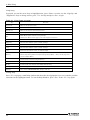
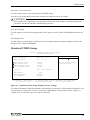
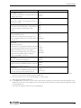
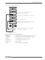
Standard CMOS Setup
Phoenix - AwardBIOS CMOS Setup Utility
Standard CMOS Features
Item Help
Date (mm:dd:yy)
Time (hh:mm:ss)
Thu, Jan 1 2001
10 : 22 : 30]
IDE
IDE
IDE
IDE
[
[
[
[
Primary Master
Primary Slave
Secondary Master
Secondary Slave
None]
None]
None]
None]
Halt On
[All , But keyboard]
Base Memory
Extended Memory
Total Memory
640K
490496K
491520K
↓→←:Move
Enter:Select
F5: Previous Values
Menu Level
Change the day, month,
year and century
+/-/PU/PD:Values F10:Save Esc:Exit F1 General Help
F6: Fail-Safe Defaults
F7: 0 timized Defaults
↓
Figure 4.3. Standard CMOS Setup Window (factory setting)
The items in Standard CMOS Setup Menu are divided into 10 categories. Each category includes no, one
or more than one setup items. Use the arrow keys to highlight the item and then use the <PgUp> or
<PgDn> keys to select the value you want in each item.
User’s Manual
23
4. BIOS Setup
Selection from the Standard CMOS Setup
This table shows the selections that you can make on the Standard CMOS Setup.
Table 4.2. Selecting item of the Standard CMOS Setup
Item
Date
Option
Month DD YYYY
Description
Sets the date on the equipment calendar clock.
Note that the ‘Day’ automatically changes
when you set the date.
Time
HH : MM : SS
Sets the time on the equipment calendar
clock.
IDE Primary Master
None
Set the type of HDD(SDD *1) to be used as the
Auto
first drive. Selecting this field changes the
Manual
screen to the submenu for manually setting
drive configuration data such as the number
of cylinders. This field is set to [Auto] by
default. You can leave it intact for normal
use.
IDE Primary Slave
None
Connection not allowed. Set to "None."
Auto
Manual
IDE Secondary Master
None
Usually, set this item to "None." If you have
Auto
connected a CD-ROM drive to the secondary
Manual
IDE connector, set this to "Auto" or "Manual"
as required.
IDE Secondary Slave
Halt On
None
Usually, set this item to "None." If you have
Auto
connected a CF card to the CF connector, set
Manual
this to "Auto" or "Manual" as required.
All Errors
The default is "All, but Keyboard"; you usually
No Errors
do not have to change this setting.
All, but Keyboard
All, but Diskette
All, but Disk/Key
Base Memory
N/A
Displays the detected amount of memory
installed on the system.
Extended Memory
N/A
Displays the detected amount of memory
installed on the system.
Total Memory
N/A
Displays the detected amount of memory
installed on the system.
*1
To use a PC-SDD V series product with a capacity of 500 MB or less, set the item to "Manual" and select the CHS
mode. For drive information such as the number of cylinders, see the manual for the PC-SDD series.
24
User’s Manual
4. BIOS Setup
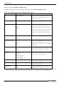
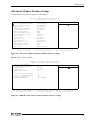
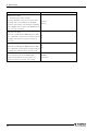
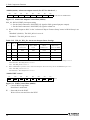
Advanced BIOS Features Setup
This section allows you to configure your system for basic operation.
Virus Warning
CPU internal Cache
External Cache
Processor Number Feature
Quick Power On Self Test
First Boot Device
Second Boot Device
Third Boot Device
Boot Other Device
Boot Up NumLock Status
Gate A20 Option
Typematic Rate Setting
x Typematic Rate (Chars/Sec)
x Typematic Delay (Msec)
Security Option
OS Select For DRAM > 64MB
Video BIOS Shadow
↓→←:Move
Enter:Select
F5: Previous Values
[Disabled]
[Enabled]
[Enabled]
[Enabled]
[Enabled]
[USB FDD]
[CDROM]
[HDD-0]
[Enabled]
[On]
[Fast]
[Disabled]
6
250
[Setup]
[Non-OS2]
[Enabled]
+/-/PU/PD:Values F10:Save Esc:Exit F1 General Help
F6: Fail-Safe Defaults
F7: 0 timized Defaults
↓
Figure 4.4. Advanced BIOS Features Window (factory setting)
Virus Warning
If you enable this feature, a warning message is displayed when a program (a virus in particular) attempts
to write to the boot sector or partition table of the hard disk drive. If a warning message appears, run an
antivirus program. This feature protects only the boot sector. Note that the feature does not protect the
entire hard disk drive.
CAUTION
A virus warning message may be displayed in response to various diagnostic and installation
programs which access the boot sector table. You should disable Virus Warning before running
such a program.
Enabled
Displays a warning message when an attempt is made to access the boot sector or hard
disk partition table.
Disabled
No warning message will appear when anything attempts to access the boot sector or
hard disk partition table.
User’s Manual
25
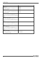
4. BIOS Setup
Description
CPU internal Cache
The default is "Enabled"; you usually do not
have to change this setting.
External Cache
The default is "Enabled"; you usually do not
have to change this setting.
Processor Number Feature
The default is "Enabled"; you usually do not
have to change this setting.
Choice
Enabled
Disabled
Enabled
Disabled
Enabled
Disabled
Quick Power On Self Test
Setting this item to "Disabled" causes Power On
Self Test (POST) to be performed in more
detail. The default is "Enabled"; you usually do
Disabled
Enabled
not have to change this setting.
First/Second/Third/Boot Device
BIOS starts booting the system in the device
order selected here. Set these items depending HDD-0
on the devices connected.
CDROM
- HDD-0 : Internal HDD (SDD) *1
HDD-1
- CD-ROM : Optional CD-ROM drive
HDD-2
(IDE connection)
HDD-3
- HDD-1 : Card plugged in the CF connector USB-FDD
on the system unit *1
USB-CDROM
(IDE connection)
USB-HDD
- HDD-2/3 : Not available
LAN
- USB-FDD/CDROM/HDD :
Disabled
Device connecting to the USB
- LAN : For boot-up from a network *2
Boot Other Device
In the case that it is not possible boot with the
First/Second/Third setting devices, BIOS tries
Disable
the boot from other devices.
Enable
The default is "Enabled"; you usually do not
have to change this setting.
Boot Up NumLock Status
Select a NumLock key status at system startup. Off
The default is "On"; you usually do not have to On
change this setting.
Gate A20 option
The default is "Fast"; you usually do not have to
change this setting.
Normal
Fast
*1
If the system unit contains no HDD (SDD), "HDD-0" causes the system to be booted from the card in the CF
*2
Boot-up from a network uses the PXE (Pre-Boot eXecution Environment) client feature.
connector on the system unit. ("HDD-1" is disabled.)
Boot-up from a LAN requires a server supporting the PXE client. (Such as a Windows remote install server)
26
User’s Manual
4. BIOS Setup
Description
Typematic Rate Setting
The default is "Disabled"; you usually do not
have to change this setting.
Choice
Disabled
Enabled
6
8
Typematic Rate (Chars/Sec)
10
This item is disabled with "Typematic Rate
12
Setting" set to "Disabled." You usually do not
15
have to change this setting.
20
24
30
Typematic Delay (Msec)
250
This item is disabled with "Typematic Rate
500
Setting" set to "Disabled." You usually do not
750
have to change this setting.
1000
Security Option
Select whether the password is required every
time the system boots or only when you enter
setup. Select whether the password be
requested whenever the system boots up or only
upon startup of Setup. The default is "Setup";
you usually do not have to change this setting.
System: The system won't boot up and access to
Setup
System
Setup will be denied unless the correct
password is entered at the prompt.
Setup: The system will boot, but access to Setup
will be denied if the correct password is not
entered at the prompt.
CAUTION
To disable security, select PASSWORD SETTING at Main Menu and then you will be asked to
enter password. Do not type anything and just press <Enter>, it will disable security. Once the
security is disabled, the system will boot and you can enter Setup freely.
User’s Manual
27
4. BIOS Setup
Description
OS Select For DRAM > 64MB
The default is " Non-OS2"; you usually do not
have to change this setting.
Video BIOS Shadow
The default is " Enabled"; you usually do not
have to change this setting.
28
Choice
Non-OS2
OS2
Disabled
Enabled
User’s Manual
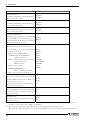
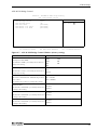
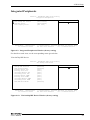
4. BIOS Setup
Advanced Chipset Features Setup
Use this menu to set up some features of the chipset.
Phoenix - AwardBIOS CMOS Setup Utility
Advanced Chipset Features
DRAM Clock/Drive Control
AGP & P2P Bridge Control
CPU & PCI Bus Control
Memory Hole
System BIOS Cacheable
Video RAM Cacheable
Power-Supply Type
VGA Share Memory Size
Select Display Device
Panel Type
Lan2 Select
Serial1 Select
Serial2 Select
WDT Output to PO2
WDT Power-on State
WDT Time-up State
HDD Select
↓→←:Move
Enter:Select
F5: Previous Values
[Press Enter]
[Press Enter]
[Press Enter]
[Disabled]
[Disabled]
[Disabled]
[ATX]
[32M]
[CRT+LCD]
[Auto]
[Enabled]
[RS232C]
[Touch Panel]
[Disabled]
[Off]
[On]
[Auto Serect]
Item Help
Menu Level
+/-/PU/PD:Values F10:Save Esc:Exit F1 General Help
F6: Fail-Safe Defaults
F7: 0 timized Defaults
↓
Figure 4.5. Advanced Chipset Features Window (factory setting)
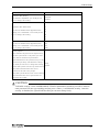
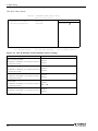
DRAM Clock / Drive Control
Phoenix - AwardBIOS CMOS Setup Utility
DRAM Clock / Drive Control Features
Current FSB Frequency
Current DRAM Frequency
DRAM Clock
DRAM Timing
DRAM CAS Latency
[By SPD]
[By SPD]
2.5
Precharge to Active(Trp)
Active to Precharge(Tras)
Active to CMD(Tras)
DRAM Command Rate
3T
6T
3T
[2T Command]
↓→←:Move
Enter:Select
F5: Previous Values
Item Help
Menu Level
+/-/PU/PD:Values F10:Save Esc:Exit F1 General Help
F6: Fail-Safe Defaults
F7: 0 timized Defaults
↓
Figure 4.6. DRAM Clock / Drive Control Window (factory setting)
User’s Manual
29
4. BIOS Setup
Description
DRAM Clock
Choice
100Mhz
The default is "By SPD"; you usually do not have to 133Mhz
change this setting.
DRAM Timing
The default is "By SPD"; you usually do not have to
change this setting.
By SPD
Manual
By SPD
DRAM CAS Latency
This item is disabled with "DRAM Timing" set to
2.5
"BySPD." You usually do not have to change this
2
setting.
Precharge to Active (Trp)
This item is disabled with "DRAM Timing" set to " 2T
By SPD." You usually do not have to change this
3T
setting.
Active to Precharge (Tras)
This item is disabled with "DRAM Timing" set to " 5T
By SPD." You usually do not have to change this
6T
setting.
Active to CMD (Trcd)
This item is disabled with "DRAM Timing" set to " 2T
By SPD." You usually do not have to change this
3T
setting.
DRAM Command Rate
The default is "2T Command"; you usually do not
have to change this setting.
30
2T Command
1T Command
User’s Manual
4. BIOS Setup
AGP & P2P Bridge Control
Phoenix - AwardBIOS CMOS Setup Utility
AGP & P2P Bridge Control
AGP
AGP
AGP
AGP
AGP
AGP
Aperture Size
Driving Control
Driving Value
Fast write
Master 1 ws write
Master 1 ws Read
↓→←:Move
Enter:Select
F5: Previous Values
[64M]
[Auto]
DA
[Disabled]
[Disabled]
[Disabled]
Item Help
Menu Level
+/-/PU/PD:Values F10:Save Esc:Exit F1 General Help
F6: Fail-Safe Defaults
F7: 0 timized Defaults
↓
Figure 4.7. AGP & P2P Bridge Control Window (factory setting)
Description
AGP Aperture Size (MB)
The default is "64M"; you usually do not have to
change this setting.
AGP Driving Control
The default is "Auto"; you usually do not have to
change this setting.
Choice
256M
16M
128M
8M
64M
4M
32M
Auto
Manual
AGP Driving Value
This item is disabled with "AGP Driving Control" Min = 0000(h)
set to "Auto."
Max = 00FF(h)
You usually do not have to change this setting.
AGP Fast Write
The default is "Disabled"; you usually do not have
to change this setting.
AGP Master 1 WS Write
The default is "Disabled"; you usually do not have
to change this setting.
AGP Master 1 WS Read
The default is "Disabled"; you usually do not have
to change this setting.
User’s Manual
Disabled
Enabled
Disabled
Enabled
Disabled
Enabled
31
4. BIOS Setup
CPU & PCI Bus Control
Phoenix - AwardBIOS CMOS Setup Utility
CPU & PCI Bus Control
CPU to PCI Write Buffer
PCI Master 0 ws Write
PCI Delay Transaction
↓→←:Move
Enter:Select
F5: Previous Values
[Enabled]
[Enabled]
[Disabled]
Item Help
Menu Level
+/-/PU/PD:Values F10:Save Esc:Exit F1 General Help
F6: Fail-Safe Defaults
F7: 0 timized Defaults
↓
Figure 4.8. CPU & PCI Bus Control Window (factory setting)
Description
CPU to PCI Write Buffer
The default is "Enabled"; you usually do not have
to change this setting.
PCI Master 0 WS Write
The default is "Enabled"; you usually do not have
to change this setting.
PCI Delay Transaction
The default is "Disabled"; you usually do not have
to change this setting.
Memory Hole
The default is "Disabled"; you usually do not have
to change this setting.
System BIOS Cacheable
The default is "Disabled"; you usually do not have
to change this setting.
32
Choice
Disabled
Enabled
Enabled
Disabled
Disabled
Enabled
Disabled
15M – 16M
Disabled
Enabled
User’s Manual
4. BIOS Setup
Description
Video RAM Cacheable
The default is "Disabled"; you usually do not have
to change this setting.
Power-Supply Type
The default is "ATX"; you usually do not have to
change this setting.
Video Share Memory Size
Specify the size of video memory. The specified
size of main memory is allocated as video
memory.
Choice
Disabled
Enabled
AT
ATX
16M
32M
64M
Select Display Device
Specify the display device.
CRT
Set this item to "LCD" when the monitor to be
LCD
used is a DVI/panel-link type (see "DVI Connector CRT+LCD
in Chapter 6.
Panel Type
Specify the panel type.
In Auto mode, the type (SVGA or XGA) of the FPD
is automatically identified with the serial signal
(COM) of the FPD at startup. If no FPD is
connected (or the FPD connected is left off), the
module enters the CRT mode (providing no
Auto
640x480
800x600
1024x768
1280x1024
display on the FPD). *1 *2 *3 *4
Lan2 Select
Enabled
Enable or disable the left LAN port.
Disabled
Serial1 Select
Switches between the RS232C (Serial1 connector)
and RS485 (in the RAS connector).
Serial2 Select
Switches between the RS232C (Serial2 connector)
and touch panel port (in the DVI connector).
*1
RS232C
RS485
RS232C
Touch Panel
In the "Auto" mode, only a CONTEC flat panel display(FPD) can be identified when connected. If any other
monitor is connected, the module enters the CRT mode.
*2
For use of "Auto," be sure to set "Serial2 Select" to "Touch Panel."
*3
FPD: Flat Panel Display LCD device
*4
If a CONTEC FPD is connected to use the “Auto” mode, the host computer may not be able to read the information on the
display, and as a result, no screen image may come up (e.g. when the host computer is turned on before the FPD, when a cable
is connected later on).
In this case, set the Panel Type to the size of the FPD used.
User’s Manual
33
4. BIOS Setup
Description
Choice
WDT Output to PO2
Set watchdog timer output to PO2.
Selecting "Enabled" connects the output of the
watchdog timer to the PIO2 pin in the RAS
connector. The output value changes depending
Disabled
Enabled
on the "WDT Power-on State" and "WDT Time-up
State" settings. (See P74)
WDT Power-on State
This item is enabled with "WDT Output to PO2"
set to " Enabled." Set the state of output from the
watchdog timer when the power is turned on.
Off
On
(See P74)
WDT Time-up State
This item is enabled with "WDT Output to PO2"
On
set to " Enabled." Set the state of output from the Off
watchdog timer when the time-up. (See P74)
HDD Select
Set the transfer mode of the HDD (SDD)
UDMA33
connected. The default is "Auto Select"; you
Auto Select
usually do not have to change this setting.
34
User’s Manual
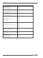
4. BIOS Setup
Integrated Peripherals
Phoenix - AwardBIOS CMOS Setup Utility
Integrated Peripherals
VIA OnChip IDE Device
VIA OnChip PCI Device
SuperIO Device
Init Display First
↓→←:Move
Enter:Select
F5: Previous Values
[Press Enter]
[Press Enter]
[Press Enter]
[PCI Slot]
Item Help
Menu Level
+/-/PU/PD:Values F10:Save Esc:Exit F1 General Help
F6: Fail-Safe Defaults
F7: 0 timized Defaults
↓
Figure 4.9. Integrated Peripherals Window (factory setting)
For details on each item, see the corresponding menu given below.
VIA OnChip IDE Device
Phoenix - AwardBIOS CMOS Setup Utility
VIA OnChip IDE Device
Onchip IDE Channel0
Onchip IDE Channel1
IDE prefetch Mode
Primary Master PIO
Primary Slave PIO
Secondary Master PIO
Secondary Slave PIO
Primary Master UDMA
Primary Slave UDMA
Secondary Master UDMA
Secondary Slave UDMA
IDE HDD Block Mode
↓→←:Move
Enter:Select
F5: Previous Values
[Enabled]
[Enabled]
[Enabled]
[Auto]
[Auto]
[Auto]
[Auto]
[Auto]
[Auto]
[Auto]
[Auto]
[Enabled]
Item Help
Menu Level
+/-/PU/PD:Values F10:Save Esc:Exit F1 General Help
F6: Fail-Safe Defaults
F7: 0 timized Defaults
↓
Figure 4.10. VIA Onchip IDE Device Window (factory setting)
User’s Manual
35
4. BIOS Setup
Description
On-Chip IDE Channel 0
The default is "Enabled"; you usually do not
have to change this setting.
On-Chip IDE Channel 1
The default is "Enabled"; you usually do not
have to change this setting.
IDE Prefetch Mode
The default is "Enabled"; you usually do not
have to change this setting.
Choice
Disabled
Enabled
Disabled
Enabled
Disabled
Enabled
Auto
Primary Master/Slave PIO
The default is "Auto"; you usually do not have to
change this setting.
Mode 0
Mode 1
Mode 2
Mode 3
Mode 4
Auto
Secondary Master/Slave PIO
The default is "Auto"; you usually do not have to
change this setting.
Mode 0
Mode 1
Mode 2
Mode 3
Mode 4
Primary Master/Slave UDMA
The default is "Auto"; you usually do not have to
change this setting.
Secondary Master/Slave UDMA
The default is "Auto"; you usually do not have to
change this setting.
IDE HDD Block mode
The default is "Enabled"; you usually do not
have to change this setting.
36
Disabled
Auto
Disabled
Auto
Disabled
Enabled
User’s Manual
4. BIOS Setup
VIA OnChip PCI Device
Phoenix - AwardBIOS CMOS Setup Utility
VIA OnChip PCI Device
VIA-3058 AC97 Audio
Onchip USB controller
Onchip USB2.0 controller
USB keyboard Support
↓→←:Move
Enter:Select
F5: Previous Values
[Auto]
[All Enabled]
[Enabled]
[Disabled]
+/-/PU/PD:Values F10:Save Esc:Exit F1 General Help
F6: Fail-Safe Defaults
F7: 0 timized Defaults
↓
Figure 4.11. OnChip USB Controller Window (factory setting)
Description
Choice
VIA-3058 AC97 Audio
Auto
Enable or disable the audio feature.
Disabled
OnChip USB Controller
Enable or disable the USB port.
All Disabled
1&3 USB Port
All Enabled
1 USB Port
1&2 USB Port
OnChip 2.0 controller
Enable or disable the use of the USB ports for
Enabled
USB2.0. When "Disabled" is selected, the USB
Disabled
port works as a USB1.1 port.
USB Keyboard Support
Select whether to emulate a USB keyboard as a
PS/2 keyboard. Set this item to "Enabled" to
install an OS with a USB keyboard. You do not Disabled
have to set this to "Enabled" to place the
Enabled
keyboard under control of the OS's driver after
starting the OS. The default is "Disabled"; you
usually do not have to change this setting.
User’s Manual
37
4. BIOS Setup
Super IO Device
Phoenix - AwardBIOS CMOS Setup Utility
Super IO Device
Onboard Serial Port 1
Onboard Serial Port 2
[3F8/IRQ4]
[2F8/IRQ3]
Item Help
Menu Level
↓→←:Move
Enter:Select
F5: Previous Values
+/-/PU/PD:Values F10:Save Esc:Exit F1 General Help
F6: Fail-Safe Defaults
F7: 0 timized Defaults
↓
Figure 4.12. SuperIO Device Window (factory setting)
Description
Onboard Serial Port 1
Select the base I/O address and IRQ for serial port 1.
- Selecting "3F8/IRQ4" assigns the port to COM1
- Selecting "2F8/IRQ3" assigns the port to COM2
- Selecting "3E8/IRQ4" assigns the port to COM3
- Selecting "2E8/IRQ3" assigns the port to COM4
in Windows.
Onboard Serial Port 2
Select the base I/O address and IRQ for serial port 2.
- Selecting "3F8/IRQ4" assigns the port to COM1
- Selecting "2F8/IRQ3" assigns the port to COM2
- Selecting "3E8/IRQ4" assigns the port to COM3
- Selecting "2E8/IRQ3" assigns the port to COM4
in Windows.
Init Display First
The default is "PCI Slot"; you usually do not have to
change this setting.
38
Choice
Disabled
3F8 / IRQ4
2F8 / IRQ3
3E8 / IRQ4
2E8 / IRQ3
Auto
Disabled
3F8 / IRQ4
2F8 / IRQ3
3E8 / IRQ4
2E8 / IRQ3
Auto
PCI Slot
AGP
User’s Manual
4. BIOS Setup
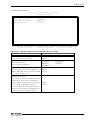
Power Management Setup
Phoenix - AwardBIOS CMOS Setup Utility
Power Management Setup
ACPI function
Power Management Option
HDD Power Down
Suspend Mode
Video Off Option
Video Off Method
MODEM Use IRQ
IRQ/Event Activity Detect
↓→←:Move
Enter:Select
F5: Previous Values
[Disabled]
[User Define]
[Disabled]
[Disabled]
[Suspend -> Off]
[V/H SYNC+Blank]
[3]
[Press Enter]
Item Help
Menu Level
+/-/PU/PD:Values F10:Save Esc:Exit F1 General Help
F6: Fail-Safe Defaults
F7: 0 timized Defaults
↓
Figure 4.13. Power Management Setup Window (factory setting)
Description
ACPI function
The default is "Disabled"; you usually do not have to
change this setting.
Power management Option
Set the power save mode.
Choice
Enabled
Disabled
User Define
Min saving
Max saving
Disabled
1 Min
2 Min
3 Min
4 Min
HDD Power Down
5 Min
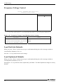
This item is enabled with "Power management
6 Min
Option" set to "User Define."
7 Min
When the module is used under Windows, the
8 Min
relevant setting in Windows overrides the setting of 9 Min
10 Min
this item.
11 Min
12 Min
13 Min
14 Min
15 Min
User’s Manual
39
4. BIOS Setup
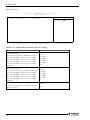
Description
Choice
Disabled
1 Min
2 Min
Suspend Mode
This item is enabled with "Power management
Option" set to "User Define."
When the module is used under Windows, the
relevant setting in Windows overrides the setting of
this item.
4 Min
6 Min
8 Min
10 Min
20 Min
30 Min
40 Min
1 hour
Video Off Option
Always On
- Always On
: The monitor remains on even in Suspend -> Off
- Suspend --> Off
: The monitor is turned off in
suspend mode.
suspend mode.
When the module is used under Windows, this
setting is not adapted.
Video Off Method
Blank Screen
Select how to turn the monitor off. The default is
V/H SYNC+Blank
"V/H SYNC+Blank"; you usually do not have to
DPMS Support
change this setting.
NA
3
Modem Use IRQ
The default is "3"; you usually do not have to change
this setting.
4
5
7
9
10
11
40
User’s Manual
4. BIOS Setup
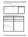
IRQ/Event Activity Detect
Phoenix - AwardBIOS CMOS Setup Utility
IRQ/Event Activity Detect
PS2KB Wakeup Select
PS2KB Wakeup from S3/S4/S5
xPower Button Lock
PS2MS Wakeup from S3/S4/S5
USB Resume from S3
VGA
LPT & COM
HDD & FDD
PCI Master
PowerOn by PCI Card
Wake Up On LAN/Ring
RTC Alarm Resume
xData (of Month)
xResume Time (hh:mm:ss)
IRQs Activity Monitoring
↓→←:Move
Enter:Select
F5: Previous Values
[Hot key]
[Disable]
[Enabled]
[Disable]
[Disabled]
[OFF]
[LPT/COM]
[ON]
[OFF]
[Disable]
[Disable]
[Disable]
0
0 : 0 : 0
[Press Enter]
+/-/PU/PD:Values F10:Save Esc:Exit F1 General Help
F6: Fail-Safe Defaults
F7: 0 timized Defaults
↓
Figure 4.14. IRQ/Event Activity Detect Window (factory setting)
Description
PS2KB Wakeup Select
This item is not used for the module. Use the module
with this item set to "Hot key" by default.
Choice
Hot key
Password
Disable
PS2KB Wakeup from S3/S4/S5
Ctrl+F1 to Ctrl+F12
This item is not used for the module. Use the module Power
with this item set to "Disabled" by default.
Wake
Any key
Power Button Lock
This item is not used for the module. Use the module
with this item set to "Enabled" by default.
Disable
Enable
PS2MS Wakeup from S3/S4/S5
Enable or disable the PS/2 mouse to turn the power Disable
on with Windows in the sleep/hibernate/shutdown
Enable
state. (Dedicated to ATX mode. See P56)
USB Resume from S3
This item is not used for the module. Use the module
with this item set to " Disabled" by default.
VGA
This item is not used for the module. Use the module
with this item set to "OFF" by default.
User’s Manual
Disable
Enable
OFF
ON
41
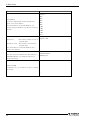
4. BIOS Setup
Description
LPT & COM
This item is not used for the module. Use the module
with this item set to "LPT/COM" by default.
HDD & FDD
The default is "ON"; you usually do not have to
change this setting.
PCI Master
The default is "OFF"; you usually do not have to
change this setting.
Power-On by PCI card
The default is "Disabled"; you usually do not have to
change this setting.
Choice
NONE
LPT
COM
LPT/COM
OFF
ON
OFF
ON
Disabled
Enabled
Wake Up On LAN/Ring
Enable or disable the LAN to turn the power on with Disabled
Windows in the sleep/hibernate/shutdown state.
Enabled
(Dedicated to ATX mode. See P56) *1
RTC Alarm Resume
If this item is set to "Enabled," the RTC (realtime
clock) alarm can be used to specify the date and time
at which to resume from suspend mode or restart the
Disabled
Enabled
system.
*1
To use the Wake Up On LAN feature, this machine must receive a magic packet to awaken itself. The magic packet
contains six bytes of FF followed by 16 contiguous copies of the MAC address (irrespective of the protocol used).
42
User’s Manual
4. BIOS Setup
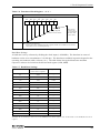
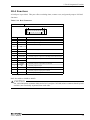
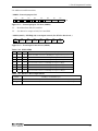
IRQs Activity Monitoring
Description
Choice
Selecting "On" (default) causes the system to resume from suspend mode whenever an event occurs.
The following table lists IRQs (Interrupt ReQuests). You usually do not have to change the setting from the
default. When an I/O devices requires servicing by the operating system, the I/O device generates an IRQ
to send the signal. When the operating system is ready for response, it generates an interrupt to execute
the requested service. Accordingly, the options available are On (default) and Off. When "Off" is selected,
the system won't enter suspend mode or return to normal mode in response to IRQs.
User’s Manual
43
4. BIOS Setup
Description
Choice
Figure 4.15. IRQs Activity Monitoring Window (factory setting)
44
User’s Manual
4. BIOS Setup
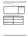
PnP/PCI Configuration Setup
Phoenix - AwardBIOS CMOS Setup Utility
PnP/PCI Configuration Setup
PNP OS Installed
Reset Configuration Data
No
[Disabled]
Item Help
Menu Level
Resources Controlled By
IRQ Resources
[Auto(ESCD)]
Press Enter
PCI/VGA Palette Snoop
[Disabled]
↓→←:Move
Enter:Select
F5: Previous Values
Select Yes if you are
using a Plug and Play
capable operating
system Select No if
you need the BIOS to
configure non-boot
devices
+/-/PU/PD:Values F10:Save Esc:Exit F1 General Help
F6: Fail-Safe Defaults
F7: 0 timized Defaults
↓
Figure 4.16. PnP/PCI Configuration Setup Window (factory setting)
Description
Choice
PNP OS Installed
No
The default is "No"; you usually do not have to
Yes
change this setting.
Reset Configuration Data
Disabled
The default is "Disabled"; you usually do not have Enabled
to change this setting.
After upgrading the BIOS, start it up with
"Enabled" selected, then select "Disabled" again.
Resource Controlled by
Auto(ESCD)
The default is "Auto(ESCD)"; you usually do not
Manual
have to change this setting.
User’s Manual
45
4. BIOS Setup
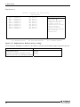
IRQ Resources
Phoenix - AwardBIOS CMOS Setup Utility
IRQ Resources
IRQ-3
IRQ-4
IRQ-5
IRQ-7
IRQ-9
IRQ-10
IRQ-11
IRQ-12
IRQ-14
IRQ-15
assigned
assigned
assigned
assigned
assigned
assigned
assigned
assigned
assigned
assigned
to
to
to
to
to
to
to
to
to
to
↓→←:Move
Enter:Select
F5: Previous Values
[PCI
[PCI
[PCI
[PCI
[PCI
[PCI
[PCI
[PCI
[PCI
[PCI
Device]
Device]
Device]
Device]
Device]
Device]
Device]
Device]
Device]
Device]
Item Help
Menu Level
Legacy ISA for devices
compliant with the
original PC AT bus
specification, PCI/ISA
PnP for devices
compliant with the
Plug and Play standard
PCI or ISA bus
architecture
+/-/PU/PD:Values F10:Save Esc:Exit F1 General Help
F6: Fail-Safe Defaults
F7: 0 timized Defaults
↓
Figure 4.17. IRQ Resources Window (factory setting)
To set resources manually, use them as "PCI Device" because this machine cannot accept ISA devices.
Description
Choice
PCI/VGA Palette Snoop
Disabled
This item is not used for the module. Use the
Enabled
module with this item set to "Disabled" by default.
46
User’s Manual
4. BIOS Setup
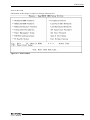
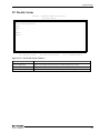
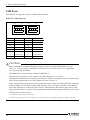
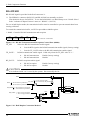
PC Health Status
Phoenix - AwardBIOS CMOS Setup Utility
PC Health Status
Current System Temp.
Current CPU1 Temperature
IN0(V)
IN2(V)
+5V
VBAT(V)
5VSB(V)
↓→←:Move
Enter:Select
F5: Previous Values
+/-/PU/PD:Values F10:Save Esc:Exit F1 General Help
F6: Fail-Safe Defaults
F7: 0 timized Defaults
↓
Figure 4.18. PC Health Status Window
Description
Choice
Current CPU Temp.
Displays the temperature detected by the CPU temperature sensor.
Current System Temp.
Displays the temperature detected by the CPU board temperature sensor.
IN0 / IN2 / +5V / VBAT / 5VSB Displays the CPU core, +3.3V, +5V, battery, and 5VSB voltages.
User’s Manual
47
4. BIOS Setup
Frequency/Voltage Control
Phoenix - AwardBIOS CMOS Setup Utility
Frequency/Voltage Control
Spread Spectrum
[Disabled]
Item Help
Menu Level
↓→←:Move
Enter:Select
F5: Previous Values
+/-/PU/PD:Values F10:Save Esc:Exit F1 General Help
F6: Fail-Safe Defaults
F7: 0 timized Defaults
↓
Figure 4.19. Frequency/Voltage Control Window (factory setting)
Description
Spread Spectrum
This item is not used for the module. Use the module
with this item set to "Disabled" by default.
Choice
Disable
Enable
Load Fail-Safe Defaults
When you press <Enter> on this item you get a confirmation dialog box with a message similar to:
Load Fail-Safe Defaults (Y/N) ? N
Press the <Y> key loads the most safe settings.
Load Optimized Defaults
When you press <Enter> on this item you get a confirmation dialog box with a message similar to:
Load Optimized Defaults (Y/N) ? N
Pressing the <Y> key loads the values optimized by the BIOS. The BIOS optimized settings are factory
defaults.
48
User’s Manual
4. BIOS Setup
Supervisor/User Password Setting
You can set either supervisor or user password, or both of then. The differences between are:
SUPERVISOR PASSWORD: can enter and change the options of the setup menus.
USER PASSWORD: just can only enter but do not have the right to change the options of the setup
menus. When you select this function, the following message will appear at the center of the screen to
assist you in creating a password.
ENTER PASSWORD:
Enter a password within eight characters and press the <Enter> key, and you will be prompted to confirm
the password. Type the password again and press <Enter>. You may also press <Esc> to abort the
selection and not enter a password.
To disable a password, just press <Enter> when you are prompted to enter the password. A message will
confirm the password will be disabled. Once the password is disabled, the system will boot and you can
enter Setup freely.
PASSWORD DISABLED.
When a password has been enabled, you will be prompted to enter it every time you try to enter Setup.
This prevents an unauthorized person from changing any part of your system configuration.
You can also set up the password so that you are prompted to enter it whenever the system is rebooted.
This would prevent unauthorized use of your computer.
You determine when the password is required within the BIOS Features Setup Menu and its Security
option. If the Security option is set to “System”, the password will be required both at boot and at entry
to BIOS Setup. If set to “Setup”, prompting only occurs when trying to enter BIOS Setup.
User’s Manual
49
4. BIOS Setup
Save & Exit Setup
Pressing <Enter> on this item asks for confirmation:
Save to CMOS and EXIT (Y/N)? Y
Pressing the <Y> key saves the changes made on the Setup screen to CMOS (EEPROM).
Pressing “Y” stores the selections made in the menus in CMOS(EEPROM) – a special section of
memory that stays on after you turn your system off. The next time you start up your computer, the BIOS
configures your system according to the value stored in CMOS(EEPROM). After saving the values the
system is restarted again.
Exit Without Saving
Pressing <Enter> on this item asks for confirmation:
Quit Without Saving (Y/N)? N
Pressing the <Y> key quits Setup without saving the changes made on the Setup screen to CMOS
(EEPROM). Quitting Setup without saving leaves the last saved settings in effect, with which the
system is rebooted after that.
50
User’s Manual
4. BIOS Setup
POST Messages
During the Power On Self-Test (POST), if the BIOS detects an error requiring you to do something to fix,
it will either sound a beep code or display a message.
POST Beep
The BIOS reports errors using two types of beeps when they cannot be reported with on-screen messages.
One is a long beep followed by two short beeps. This indicates an error in the video system.
The other is a repetition of a long beep, indicating a DRAM error.
User’s Manual
51
4. BIOS Setup
Error Messages
One or more of the following messages may be displayed if the BIOS detects an error during the POST.
CMOS checksum error
CMOS memory recording BIOS Setup information contains an invalid checksum.
This indicates that invalid data has been written to CMOS memory. The error occurs,
for example, when the BIOS is upgraded or when the power is turned off while BIOS
Setup is saving data.
You can recover from the error by writing valid Setup data unless the error is caused by
a fault in CMOS memory.
DISK BOOT failure
[INSERT SYSTEM DISK AND PRESS ENTER]
No boot device was found.
This message appears, for example, when the BIOS cannot find any drive from which
to boot the system. Check whether a bootable device has been connected and whether
the connectors and cables have been plugged correctly.
Error encountered initializing hard drive
Error initializing hard disk controller
Hard disk(s) fail (80)
Hard disk(s) fail (40)
Hard disk(s) fail (20)
Hard disk(s) fail (10)
Hard disk(s) fail (08)
The HDD (SDD) is abnormal.
These messages appear when the HDD (SDD) connected is detected to be abnormal in
some way. If any of the messages is displayed, check the connection of the drive and
its settings.
Primary IDE Channel no 80 conductor cable installed
Secondary IDE Channel no 80 conductor cable installed
These messages appear when the system unit cannot recognize a connected ATA100
IDE device as an ATA100 device. If either of the messages is displayed, check that
"HDD Select" in the "Advanced Chipset Features" menu has been set to "Auto Select."
52
User’s Manual
4. BIOS Setup
Keyboard error or no keyboard present
This message appears with no keyboard connected.
The message may also appear if a key remains held down during a boot-up.
If this message is displayed, check the connection of the keyboard and its situation
during startup.
If you use the module with no keyboard connected, use BIOS Setup to set "Halt On" in
the "Standard CMOS Feature" menu to "All, But Keyboard."
Keyboard is locked out – Unlock the key
A key remains held down during a system boot. Check that the keyboard is connected
correctly and that no key is pressed during a system boot.
Memory address error at…
Memory parity error at…
Memory verify error at…
Memory test fail
These error messages appear when system memory is abnormal.
They may appear when a BIOS Setup value is abnormal.
Run BIOS Setup again if possible.
Press F1 to disable NMI, F2 to REBOOT
This message appears when the system detects a nonmaskable interrupt (NMI).
You can select whether to continue processing with the NMI disable or to reboot the
system with the NMI enabled after the message is cleared.
Press a key to REBOOT
This message appears along with another message for an error, indicating that the error
requires a reboot.
Press any key and the system will reboot.
System halted, (CTRL-ALT-DEL) to REBOOT…
This message appears along with another message as well, but indicating that the
system has been hung. Press and hold down the <CTRL> and <ALT> keys and press
<DEL> to re-start the system.
User’s Manual
53
4. BIOS Setup
BIOS ROM checksum error – System halted
BIOS ROM data is invalid. This message appears, for example, when an attempt to
upgrade the BIOS has failed. BIOS ROM must be removed for repair.
54
User’s Manual
5. Each Component Function
5. Each Component Function
Component Identification
POWER LED
ACCESS LED
DVI
STANDBY POWER LED
USB
KEYBOARD
SERIAL1
SERIAL1
USB
DVI
KB
SPK
LINE OUT
RST
RESET
SERIAL2
PCMCIA
PWR
ACCESS
SPD
RAS
SERIAL2
ACT
LNK ACT
LAN2
PCMCIA
LNK
LAN1
DC-IN
LAN2
LAN1
FG V- V+
RAS
10VDC-IN
SECONDARY IDE
CF Slot
HDD
< Left side >
Figure 5.1. Component Identification
Table 5.1. Component Identification
Name
Function
LINE OUT
Line out (φ3.5 PHONE JACK)
KEYBOARD
Keyboard connector (MINI-DIN, 6pin)
SERIAL1
Serial port 1 connector (9pin, male D-SUB)
SERIAL2
Serial port 2 connector (9pin, male D-SUB)
USB
USB port connector
LAN1, LAN2
Ethernet connector (RJ-45)
PCMCIA
PCMCIA card slot
DVI
DVI connector (29pin, DVI-I)
RAS
RAS function (9pin, female D-SUB)
RESET
Hard reset push button
POWER LED
Power ON indicator
ACCESS LED
Internal hard disk access lamp
STANDBY POWER LED
Stand by Power LED (Dedicated to ATX mode, coming on at shutdown) *1
SECONDARY IDE
Secondary IDE connector (dedicated 36pin half-pitch connector)
CF Slot
CF Card Slot(Secondary IDE connection)
*1
See the list of the next page for differences between ATX and AT modes.
User’s Manual
55
5. Each Component Function
Mode
Setting method
At shutdown (standby/power-off state)
- In case of Windows XP
Open the Control Panel, select "Turn off
Computer" from "Performance and
Maintenance," then check "Enable
ATX
mode
Advanced Power Management support."
under the APM tab, then reboot the system
- In case of Windows 2000
Check "Enable Advanced Power
- SPD (standby power indicator LED) comes on.
- Recycle the DC power supply, press any key on the PS/2
keyboard, click the PS/2 mouse button (see P41), or use
WakeupOnLan (see P42) to return to the power-on state.
Management support." under the APM tab
from the Control Panel – Power Option,
then reboot the system
AT mode
56
Uncheck the above option, then reboot the
Recycle the DC power supply to return to the power-on
system.
state.
User’s Manual
5. Each Component Function
Line out Interface
A line output connector is provided, named SPK (3.5φ stereo mini jack). You can plug a headphone or
amplifier-integrated speakers into this connector.
Audio driver
The audio driver is required to use the line output interface.
Visit the CONTEC web site to download the audio driver (IPC-SLIB-01) for the OS running on your
BOX-PC.
For the download, see Chapter 6 “List of Options".
Keyboard / Mouse Interface
The BOX-PC is equipped with a keyboard connector named KB (MINI-DIN 6P).
A PS/2 mouse can also be used with the bundled keyboard/mouse branch cable.
Table 5.2. Keyboard / Mouse Interface
Connector type Equivalent to the MD-DS12300-14S-14(JST)
1
2
3
4
5
6
Pin No.
Signal name
Pin No.
1
+KBD DATA
5
+KBD CLK
2
+MOUSE DATA
6
+MOUSE CLK
3
GND
SHELD
GND
4
+5.0V DC
---
User’s Manual
Signal name
57
5. Each Component Function
Serial Port Interface
Serial port 1, 2(RS-232C port)
The BOX-PC is equipped with two RS-232C-compliant serial port connectors (SERIAL1: Serial port 1
and SERIAL2: Serial port 2). You can use BIOS Setup (described in Chapter 4) to configure an I/O
address, interrupt and unused state for each of the ports independently. (The same I/O address and IRQ
cannot be shared with any other device.)
Note that Serial Ports 1 and 2 are shared ports also available as the RS-422/485 and touch panel
interfaces, respectively. The interfaces sharing each serial port are mutually exclusive. *1
To use the serial port for the interface other than RS-232C, see the relevant page.
*1
The serial ports are set as follows by default: SERIAL1: RS232C / SERIAL2: Touch Panel. To use Serial Port 2, run
BIOS Setup to set "Serial2 Select" in the "Advanced Chipset Features" menu to "RS232C". (See P33)
Table 5.3. Serial port 1, 2 I/O address and Interrupts
COM
I/O address
Interrupt
1
3F8h-3FFh
2
2F8h-2FFh
IRQ 3
3
3E8h-3EFh
IRQ 4
4
2E8h-2EFh
The BIOS defaults to the following factory settings:
Serial port 1: COM1(3F8h-3FFh),IRQ4
Serial port 2: COM2(2F8h-2FFh),IRQ3
Table 5.4. Serial Port Connector
Connector used on the unit
6
Pin No. Signal name
58
9
1
9-socket D-SUB (MALE)
No.4-40UNC
Inch thread
5
Meaning
Direction
1
CD
Carrier detect
2
RD
Received data
3
TD
Transmitted data
Output
Output
Input
Input
4
DTR
Data terminal ready
5
GND
Signal ground
-----
6
DSR
Data set ready
Input
7
RTS
Request to send
Output
8
CTS
Clear to send
Input
9
RI
Ring indicator
Input
User’s Manual
5. Each Component Function
I/O Addresses and Instructions
The I/O addresses and instructions of COM1 are shown next.
Table 5.5. I/O Addresses
I/O address
DLAB
Read/Write
Register
03F8H
0
W
Transmitter holding register
THR
R
Receive buffer register
RBR
1
W
Divisor latch register (LSB)
DLL
03F9H
1
W
Divisor latch register (MSB)
DLM
0
W
Interrupt enable register
IER
03FAH
X
R
Interrupt ID register
IIR
03FBH
X
W
Line control register
LCR
MCR
03FCH
X
W
Modem control register
03FDH
X
R
Line status register
LSR
03FEH
X
R
Modem status register
MSR
03FFH
X
R/W
Scratch register
SCR
DLAB (Divisor Latch Access Bit) : The value in bit 7 of the line control register
User’s Manual
59
5. Each Component Function
Table 5.6. Function of Each Register < 1 / 4 >
I/O address
03F8H
Description
THR: Transmitter Holding Register [DLAB=0]
D7 D6 D5 D4 D3
D2
D1
D0
bit0
LSB
bit7
MSB
Register dedicated to write transmitted data to
03F8H
RBR: Reciever Buffer Register [DLAB=O]
D7 D6 D5 D4 D3
D2
D1
D0
bit0
LSB
bit7
MSB
Register dedicated to read received data from
03F8H
DLL: Divisor Latch (LSB) [DLAB=1]
D7 D6 D5 D4 D3
D2
D1
D0
bit0
LSB
bit7
MSB
Baud rate setting register (LSB)
03F9H
DLH: Divisor Latch (MSB) [DLAB=1]
D7 D6 D5 D4 D3
D2
D1
D0
bit0
LSB
bit7
MSB
Baud rate setting register (MSB)
03F9H
IER: Interrupt Enable Register [DLAB=0]
D7 D6 D5 D4 D3
D2
D1
0
0
0
0
EMS
D0
ELSI ETHREI ERDAI
Received data
Interrupt enable
Received data register empty
Interrupt enable
Receiver line status
Interrupt enable
Modem status interrupt enable
[Always used at 0.]
1: Enable interrupt
0: Disable interrupt
60
User’s Manual
5. Each Component Function
Table 5.6. Function of Each Register < 2 / 4 >
I/O address
03FAH
Description
IIR : Interrupt Identification Register
D7
D6
D5
D4
D3
D2
0
0
0
0
D1
D0
0
Interrupt details
bit2 bit1 bit0 Priority
03FBH
1: Do not generate interrupts
0: Generate interrupts
Description
Interrupts are not generated.
0
0
1
1
1
0
1
0
0
2
Generated when the receive buffer register is ready.
Cleared when the receiving buffer is read.
0
1
0
3
Generated when the transmitter holding register is
empty. Cleared when the IIR is read or when
transmitted data is written to THR.
0
0
0
4 (low)
1 (high) Generated by overrun, parity, framing error or break
interrupt.
Cleared when the line status register is read.
Modem status interrupt is generated.
(CTS, DSR, RI, CD)
Cleared when the modem status register is read.
LCR : Line Contror Regester
D7
D6
D5
D4
D1 D0 Bit table
D3
D2
D1
D0
0
0
5
0
1
6
1
0
7
1
1
8
0 : 1 STOP bit
1 : 1.5 STOP bits at 5-bit length
2 STOP bits at 6-, 7-, or 8-bit length
0 : Disable parity
1 : Enable parity
0 : Odd parity
1 : Even parity
0 : Disable stick parity
1 : Enable stick parity
0 : Break signal off
1 : Send break signal
DLAB (Divisor Latch Access Bit)
In order to access the divisor latch register, you need to set the bit
to 1. To access another register, set the bit to 0.
User’s Manual
61
5. Each Component Function
Table 5.6. Function of Each Register < 3 / 4 >
I/O address
03FCH
Description
MCR: Modem Control Register
D7
D6
D5
D4
D3
0
0
0
Loop IRQ
D2
X
D1
D0
RTS DTR
DTR 0 : Inactive
[HIGH]
1 : Active
[LOW]
RTS 0 : Inactive
[HIGH]
1 : Active
[LOW]
Interrupt control bit
0 : Disable
1 : Enable
Diagnostic local loop-back test
0 : Disable
1 : Enable
03FDH
LSR: Line Status Regester
D7
0
D6
D5
TEMT THRE
D4
D3
D2
D1
D0
BI
FE
PE
OE
DR
Data ready
(1 for existence of received data)
Overrun error
(1 for occurrence of an error)
Parity error (1 for occurrence of an error)
Framing error (1 for occurrence of an error)
Break interrupt (1 for detection of break state)
Transmitter holding register empty
(1 for transmission buffer being empty)
Transmitter empty
(Set to 1 when both transmitter holding register and
transmitter shift register are empty.)
62
User’s Manual
5. Each Component Function
Table 5.6. Function of Each Register < 4 / 4 >
I/O address
Description
03FEH
MSR : Modem Status Register
D7 D6 D5
D4 D3
DCD
RI
D2
D1
D0
DSR CTS DDCD TERI DDSR DCTS
Delta CTS
Delta DSR
Trailing edge RI
Delta data carrier detect
CTS
Since these
statuses are
not used with
RS-485, data
is not valid.
DSR
RI
DCD
03FFH
SCR : Scratchpad Register
This is an 8-bit, readable/writable register which is available to the user to
allow data to be saved temporarily.
Baud Rate Settings
A baud rate is set by software by dividing the clock input (1.8432MHz). The baud rate in terms of
hardware can be set to a maximum of 115,200 bps. The baud rates available in practice depend on the
operating environment (cable, software, etc.). The table below lists typical baud rates and their
respective values to be written to the divisor latch register (LSB, MSB).
Table 5.7. Baud Rate Settings
Baud rate to be set
Value to be set
Setting error (%)
in the divisor register
50
2304
75
1536
-----
110
1047
0.026
134.5
857
0.058
150
768
---
300
384
---
600
192
---
1200
96
---
1800
64
---
2000
58
0.69
2400
48
---
3600
32
---
4800
24
---
7200
16
---
9600
12
---
19200
6
---
Example: To set 9,600 bps, write "00" to the (MSB) divisor latch register and "12 (decimal)" to the (LSB) divisor latch
register.
User’s Manual
63
5. Each Component Function
USB Ports
The BOX-PC is equipped with four USB interface channels.
Table 5.8. USB Connector
Pin No.
C4
C1
A4
A1
D4
D1
B4
B1
Signal name
Pin No.
Signal name
A1
USB0 Vcc
B1
USB1 Vcc
A2
USB0 -Data
B2
USB1 -Data
A3
USB0 +Data
B3
USB1 +Data
A4
USB0 GND
B4
USB1 GND
C1
USB2 Vcc
D1
USB3 Vcc
C2
USB2 -Data
D2
USB3 -Data
C3
USB2 +Data
D3
USB3 +Data
C4
USB2 GND
D4
USB3 GND
CAUTION
-
When installing the Windows2000/XP package versions from USB-CDROM, there are no
note.*1*2 In recovering pre-installation OS, please recover with reference to an appending
recovery procedure document.
-
USB-HDD boot is checking only starting of MS-DOS.*2
-
The total current capacity of four channels of USB connectors is 1 A or less.
Although the maximum current capacity per channel is 500 mA, configure the devices such that the
total current consumption by the four channels does not exceed 1 A.
-
There is apparatus by which current flows backwards from a connection cable to BOXPC at the time
of power supply off of BOXPC among USB apparatus. Since you may be unable to start BOXPC
when such apparatus is connected, please remove USB apparatus and connect again after a power
supply injection. However, please connect again before performing apparatus detection, when using
USB apparatus as a boot device.
*1 Only SP4(or later) is about Windows 2000.
*2 Basic functional operation of a screen display etc is checked. However, no operation of the functions of OS is guaranteed.
64
User’s Manual
5. Each Component Function
Ethernet
The module is equipped with two channels of Fast Ethernet.
- Network type
: 100BASE-TX/10BASE-T
- Transmission speed *
: 100M/10M bps
- Max. network path length
: 100m/segment
- Controller
: RTL8139DL(Realtek)
* Operation at 100Mbps requires a category 5 cable.
Table 5.9. Ethernet Connector
Connector type
RJ-45
1
Act
8
Link
Pin No.
Signal name
Meamimg
1
TD+
Transmitted data (+)
2
TD-
Transmitted data (-)
3
RD+
Received data (+)
4
N.C.
Not connected
5
N.C.
Not connected
6
RD-
Received data (+)
7
N.C.
Not connected
8
N.C.
Not connected
LEDs for the display of network status
LINK
: Normal connection display
ACT
: Transmission/reception indicator
LAN drivers
Visit the CONTEC web site to download the LAN driver (IPC-SLIB-01) for the OS running on your
BOX-PC. For the download, see Chapter 6 “List of Options"
User’s Manual
65
5. Each Component Function
PC Card Slots
PCMCIA compliant, CardBus compatible card slots are provided [TYPE II x 1 size]
Slot
Figure 5.2. Slot Numbers and Locations
Attaching the Metal Brace to Keep the Card in Place
Bind screws (M3 x 6)
(Bundled)
Figure 5.3. Attaching the Metal Brace to Keep the Card in Place
Power Supply to the Card
The voltage that can be used and the current capacity are as shown below:
Table 5.10. Power Supply to the Card
66
Voltage
Current capacity (Max.)
+5V
250mA/Slot
+3.3V
250mA/Slot
+12V
Not supplied.
User’s Manual
5. Each Component Function
DVI Connector
This is the DVI connector for the CRT/LCD. You can use it to connect a display (even a D-SUB-15pin
connector is acceptable by using the bundled DVI-analog RGB adapter) or a CONTEC Panel Link
display *1. The pin assignments are as follows.
Table 5.11. DVI Connector
Connector type
DVI-I 29pin
C4
C3
16
24
17
8
1
9
C5
C2
C1
Pin No.
Signal name
Pin No.
Signal name
Pin No.
1
DATA2-
13
N.C.
C1
RED
2
DATA2+
14
+5V
C2
GREEN
15
GND
C3
BLUE
3
4
N.C.
16
HPD
C4
HSYNC
5
N.C.
17
DATA0-
C5
GND
6
DDC CLK
18
DATA0+
7
DDC
DATA
19
8
VSYNC
20
9
DATA1-
21
10
11
12
*1
DATA2
SHIELD
Signal name
DATA1+
DATA1
SHIELD
N.C.
22
DATA0
SHIELD
TXD
RXD
DATA0
SHIELD
23
CLK+
24
CLK-
To use a CONTEC panel display, select "Touch Panel" to the "Serial2 Select" in the "Advanced Chipset Features"
menu or the display mode of the connected display with the "Panel Type." (See P33)
CAUTION
-
-
Installation of the display driver for windows sets resolution as 1024 x 7684. When you use it in
different resolution, please re-setup in the display mode before re-starting.
When it re-starts without setting up, it becomes impossible to express a screen as the monitor which
cannot display 1024 x 768.
The display is not guaranteed about resolution except 720 x 400, 640 x 480, 800 x 600, 1024 x 768.
There is a case where it cannot be displayed that the display mode more than the recommendation
resolution of a display is set up.
User’s Manual
67
5. Each Component Function
Table 5.12. DVI-Analog RGB conversion adapter
Connector type
C5
C4
C3
DVI-I 29pin
C2
C1
6
17
39.40
8
24
33.00
16
1
11
5
15
1
10
15.00
6.20
30.00
5.80
[mm]
Analog RGB signals
68
Pin No.
Signal name
Pin No.
1
RED
9
Signal name
HPD
2
GREEN
10
GND
3
BLUE
11
N.C.
4
N.C.
12
DDC DATA
HSYNC
5
GND
13
6
GND
14
VSYNC
7
GND
15
DDC CLK
8
GND
User’s Manual
5. Each Component Function
The table below lists the LCDs that can be connected.
Note that in order to connect an LCD, you need a connecting cable.
Table 5.13. LCD Displays Acceptable
Display
Model
6.5 inch TFT with
a panel-mounting
IPC-DT/S61VT-DC1
touch panel
6.5 inch TFT with
built-in touch panel
10.4 inch TFT with
a panel-mounting
touch panel
10.4 inch TFT with
built-in touch panel
12 inch TFT with
a panel-mounting
touch panel
12 inch TFT with
built-in touch panel
15 inch TFT with
a panel-mounting
touch panel
15 inch TFT with
built-in touch panel
12 inch TFT with a
desktop/wall-mounted
touch panel
IPC-DT/S65VT-DC1
Signal name
Display
Analog RGB
VGA
DVI
(640 x 480)
Analog RGB
VGA
DVI
(640x x480)
IPC-DT/M61VT-DC1
Analog RGB
VGA
IPC-DT/M61VT-AC0
DVI
(640 x 480)
IPC-DT/M65VT-DC1
Analog RGB
VGA
DVI
(640 x 480)
IPC-DT/L61SVT-DC1
Analog RGB
SVGA
IPC-DT/L61SVT-AC0
DVI
(800 x 600)
IPC-DT/L40S(PC)T
Panel link
IPC-DT/L65SVT-DC1
SVGA
(800 x 600)
Analog RGB
SVGA
DVI
(800 x 600)
IPC-DT/H61XT-DC1
Analog RGB
XGA
IPC-DT/H61XT-AC0
DVI
(1024 x 768)
IPC-DT/H40X(PC)T
Panel link
IPC-DT/H65XT-DC1
IPC-DT/L440(PC)TA
IPC-DT/L440(PC)TB
XGA
(1024 x 768)
Analog RGB
XGA
DVI
(1024 x 768)
Panel link
SVGA
(800 x 600)
CAUTION
When using IPC-DT/x6x series, even if it uses "Auto detect", when the display has shifted in the
direction of length, please adjust by "V positionSP" of IPC-DT/x6x series.
Display Driver
Visit the CONTEC web site to download the Display driver (IPC-SLIB-01) for the OS running on your
BOX-PC.
For the download, see Chapter 6 “List of Options".
User’s Manual
69
5. Each Component Function
Serial Interface for Touch Panel (Inside the DVI connector)
The BOX-PC is equipped with a serial port (Serial port 2) to communicate with a touch panel when an
LCD equipped with a touch panel is used. *1
Visit the CONTEC web site to download the Touch Panel driver (IPC-SLIB-01) for the OS running on
your BOX-PC.
For the download, see Chapter 6 “List of Options".
*1
The SERIAL2 connector (RS-232C) and touch panel function are mutually exclusive.
(In the default settings, the touch panel function is used.) (See P33)
70
User’s Manual
5. Each Component Function
RAS Functions
A RAS port is provided. This port offers watchdog timer, remote reset, and general-purpose I/O RAS
functions.
Table 5.14. RAS Connector
Connector type
15pin D-SUB(FEMALE) (DALC-J15SAF-20L9) JAE
8
1
15
9
Pin No.
Signal name
1
SPK
External speaker signal
9
GND
External speaker ground
2
TX +
RS-485 transmitting line
10
TX -
3
RX +
11
RX -
4
NCOM
12
PO2/WDT
5
PO0
13
PO1
6
NCOM
7
PI1
14
PI2/IRQ
8
PCOM
15
PI0
Function
RS-485 receiving line
Minus common dedicated to PO2
General-purpose output or watchdog timer alarm output
General-purpose output
General-purpose output minus common
General-purpose input
General-purpose input or interrupt input
General-purpose input plus common
General-purpose input
*Fastening screw: No. 4-40UNC inch thread
RAS Port address: 4000h to 4006h
CAUTION
Pin 4 NCOM (minus common dedicated to PO2) and pin 6 NCOM (minus common shared by PO0
and PO1) are electrically separated from each other.
User’s Manual
71
5. Each Component Function
Watchdog Timer
The watchdog timer is started by output of A5 to I/O port address 4002h. A second output of A5 to the
same port within the specified expiration time once again triggers the watchdog timer. If a time-out
occurs, a reset or an interrupt is generated according to the 4004h port setting or an alarm is output
according to the 4004h port setting.
The time-out period can be set between 1 and 255 seconds depending on the timer value setting for the
WDT counter port (4003h).
The watchdog timer stops by reading port 4002h. The alarm-out output is cancelled at the same time.
The alarm out is output from the RAS connector's PO2/WDT (12-pin) and cancelled when reset.
The alarm-out output can be set to BIOS startup by BIOS setup (see Chapter 4), watchdog timer startup,
or watchdog timer time-up.
Specifications
-
Time to be set
: 1sec to 255sec
-
Interrupt or reset
: Resets or generates an interrupt at time-up (Port setting).
-
External alarm output
: Optocoupler isolated open-collector output (the output status is set
by software). For more information, see the general-purpose I/O
specifications.
-
I/O addresses
: 4001h to 4005h (RAS port)
72
User’s Manual
5. Each Component Function
How to Use the Watchdog Timer
BIOS setting
Power ON
Set event
output control
... Output data to ports 4001h and 4004h to set the
output mode of event, external alarm.
... Read port 4002h, stop the WDT, and turn off alarm output.
Instruct
WDT to stop
Set timer value
Start & clear WDT
... Output set data to port 4003h.
... Output of A5h to port 4002h starts the WDT and output
of A5h to the same port clears the timer.
Application
NO
... To modify the timer value during operation, the WDT
needs to be stopped temporarily.
Modify timer
value?
YES
*WDT: Watch Dog Timer
Figure 5.4. How to Use the Watchdog Timer
Example use:
To assign IRQ5 to the event whose time-up value is 15sec:
Out 4004h 02h
: Set the event at the time of WDT expiration to IRQ5.
In 4002h
: Stop the WDT timer and cancel the alarm.
Out 4003h 0Fh
: Set the WDT expiration time to 15sec.
Out 4002h A5h
: Start the WDT.
In 4002h
: Stop the WDT and cancel the alarm.
User’s Manual
73
5. Each Component Function
* 4001h (bit4-6): Alarm out output control (See P77 for bits 0 to 3.)
D7
D6
D5
D4
D3
D2
D1
D0
---
WD_S1
WD_S0
PO2_M
RESET
PIM2
PIM1
PIM0
R/W (default: XXXX0000b)
Figure 5.5. Alarm Out Output Control Port (4001h)
PO2_M : PO PO2/WDT pin output setting
0 : Set the RAS connector's PO2/WDT(12) signal to PO2 (general-purpose output).
1 : Set the RAS connector's PO2/WDT(12) signal to alarm out.
*1 When "WDT Output to PO2" in the "Advanced Chipset Features Setup" menu in BIOS Setup is set
to:
"Disabled" (default): The PO2_M bit is set to 0.
"Enabled": The PO2_M bit is set to 1.
Table 5.15. WD_S1, WD_S0: Alarm-out Output Status Settings
External alarm output status
WD_S1 WD_S0
When BIOS
starts
When
WDT starts
0
OFF
OFF
OFF
ON
0
OFF
OFF
ON
OFF
1
OFF
ON
ON
OFF
1
OFF
ON
OFF
ON
*3
0
1
1
0
*2
When power is
turned off
*2
When time
expires on WDT
When "WDT Power-on State" in the "Advanced Chipset Features Setup" menu in BIOS Setup is set to:
"Off" (default): The WD_S0 bit is set to 0.
"On": The WD_S0 bit is set to 1.
*3
When "WDT Time-up State" in the "Advanced Chipset Features Setup" menu in BIOS Setup is set to:
"Off": The WD_S1 bit is set to 1.
"On (default)": The WD_S2 bit is set to 0.
* 4002h WDT control
D7
D6
D5
D4
D3
D2
D1
D0
R/W
Figure 5.6. WDT Control Port (4002h)
R
: Cancels WDT stop/alarm.
Read data is undefined.
W : Start and clear the WDT.
Write A5h to start and clear the WDT.
74
User’s Manual
5. Each Component Function
* 4003h: WDT counter
D7
D6
D5
D4
D3
D2
D1
D0
T7
T6
T5
T4
T3
T2
T1
T0
W
Figure 5.7. WDT Counter Port (4003h)
W : Writes watchdog timer count data.
Write watchdog timer counter expiration time data.
→
→
→
→
1sec
8sec
15sec
30sec
01h
08h
0Fh
1Eh
* 4004h : Event output control
D7
D6
D5
D4
D3
D2
D1
D0
---
---
---
---
RESET
WM2
WM1
WM0
R/W (Default: XXXX0000b)
Figure 5.8. Event Output Control Port (4004h)
Table 5.16. WM2-WM0: Interrupt Output Modes
WM2
WM1
WM0
Interrupt output at occurrence of WDT errors
0
0
0
Disable an interrupt when the watchdog timer causes a time-out
0
0
1
Output to NMI when the watchdog timer causes a time-out.
0
1
0
Output to IRQ5 when time expires on the WDT.
0
1
1
Output to IRQ7 when time expires on the WDT.
1
0
0
Output to IRQ9 when time expires on the WDT.
1
0
1
Output to IRQ10 when time expires on the WDT.
1
1
0
Output to IRQ11 when time expires on the WDT.
Table 5.17. RESET: Reset Output Modes
RESET
0
1
Note!
RESET output at occurrence of WDT errors
Inhibits RESET output when time expires on the WDT.
Allows RESET output when time expires on the WDT.
When time expires on WDT, the alarm-out is output irrelevant to the settings of the port for controlling event
output.
* 4005h : RAS status port
D7
D6
D5
D4
D3
D2
D1
D0
WDT
R
(Default: XXXXXXX0b)
Figure 5.9. RAS Status Port (4005h)
R
: RAS status port
WDT : WDT status
This is the WDT status bit. This bit is cleared when the WDT stops (read port 4002h).
0 : The WDT is either stopped or counting.
1 : The time set on the WDT expired.
User’s Manual
75
5. Each Component Function
General-purpose I/O
The BOX-PC is equipped with three general-purpose isolated signals each for input and output in the
RAS connector. The input signals can also be used for interrupt input or remote reset input.
Specifications
[ Input ]
-
Input specifications
:
Current-driven input by Optocoupler isolation.
-
Input resistance
:
4.7kΩ
-
Input signal count
:
3 [One of them can be used for remote reset and interrupt input.
(bit2<fixed>)]
-
Input protection circuit
:
Equipped with a reverse-connection protection diode
-
Input response time
:
Less than 100μsec
-
External circuit power supply :
12 to 24VDC (±10%)
[ Output ]
-
Output specifications
:
Open-collector output by Optocoupler isolation.
-
Output rating
:
Max. 30VDC, 100mA
-
Output signal count
:
3 [One of them can be used for WDT alarm output.
(bit2<fixed>)]
-
Output response time
:
Less than 300μsec
[ Common ]
-
I/O addresses
4000h and 4001h
How to Use General-purpose I/O and Remote Reset
Event output
control
I/O
... Output data to port 4001h to set PI2 mode.
... Implement input and output with port 4000h.
Figure 5.10. How to Use General-purpose I/O and Remote Reset
76
User’s Manual
5. Each Component Function
I/O Addresses and Instructions
* 4000h : General-purpose I/O
D7
D6
D5
D4
D3
D2
D1
D0
PIO2
PIO1
PIO0
R/W
Figure 5.11. General-purpose I/O Port (4000h)
R : Read data from PI0, PI1 and PI2.
W : Set data to be output to PO0, PO1 and PO2.
* 4001h (bit0-3): PI2/IRQ(14) event input control (See P74 for bits 4 to 6.)
D6
D5
D4
D3
D2
D1
D0
WD_S1
WD_S0
PO2_M
RESET
PIM2
PIM1
PIM0
D7
Figure 5.12. Event Input Control Port (4001h)
Table 5.18. PIM2-PIM0
PIM2
PIM1
PIM0
PI2/IRQ (14) interrupt input
0
0
0
Inhibit the RAS connector's PI2/IRQ (14) signal interrupt to be set.
0
0
1
Input the RAS connector's PI2/IRQ (14) signal to NMI.
0
1
0
Input the RAS connector's PI2/IRQ (14) signal to IRQ5.
0
1
1
Input the RAS connector's PI2/IRQ (14) signal to IRQ7.
1
0
0
Input the RAS connector's PI2/IRQ (14) signal to IRQ9.
1
0
1
Input the RAS connector's PI2/IRQ (14) signal to IRQ10.
1
1
0
Input the RAS connector's PI2/IRQ (14) signal to IRQ11.
Table 5.19. RESET: Reset Input Modes
RESET
PI2/IRQ (14)'s RESET input
0
Inhibit the remote reset input function of the RAS connector's PI2/IRQ (14) signal.
1
Use as the remote reset input function of the RAS connector's PI2/IRQ (14) signal.
User’s Manual
77
5. Each Component Function
RS-422/485
RS-422/485 signal is provided in the RAS connector *1.
*1 The SERIAL1 connector (RS-232C) and RS-422/485 are mutually exclusive.
(The default is the use for RS232C. To use the RS-422/485, use BIOS Setup to set "Serial1 Select"
in the "Advanced Chipset Features" menu to " RS485." (See P33)
For use in half-duplex mode, the transmission buffer must be controlled to prevent transmit data from
causing collisions.
To control the transmission buffer, set RTS or port address 4006h register.
* 4006h : Control of RS-485 transmission and reception
D4
D3
D2
RE_GATE TE_GATE TE_SEL
D1
D0
rsv*
R/W (Default: xxx00000b)
rsv*
Figure 5.13. RS-485 Transmission and Reception Control Port (4006h)
TE_SEL : Select the RS-485 transmission enable signal.
TE_GATE :
RE_GATE :
0 :
Sets the RTS signal to the RS-485 transmission enable signal. (factory setting)
1 :
Sets the TE_GATE value to the RS-485 transmission enable signal.
RS-485 transmission enable signal. Valid only when the TE_SEL value is "1."
0 :
RS-485 transmission
Enable (factory setting)
1 :
RS-485 transmission
Disable
RS-485 reception enable signal.
0 :
RS-485 reception
Enable (factory setting)
1 :
RS-485 reception
Disable
CAUTION
A bit indicated with "rsv" is used by the system. Do not modify the bit.
TXD
RTS
0 : Transmission prohibited
D
TE_SEL
1 : Transmission permitted
TE_GATE
0 : Controlled by RTS
1 : Controlled by TE_GATE
0
1
RX-(11)
0 : Transmission permitted
1 : Transmission prohibited
RE_GATE
RX+ (3)
21
VCC
0 : Receiving permitted
1 : Receiving prohibited
47k
JP1
TX-(10)
TX+ (2)
120Ω
6.2k
RXD
R
6.2k
47k
Figure 5.14. Half-Duplex Connection Method
78
User’s Manual
5. Each Component Function
TXD
RTS
D
0 : Transmission prohibited
TE_SEL
0
1
1 : Transmission permitted
TE_GATE
0 : Controlled by RTS
1 : Controlled by TE_GATE
0 : Transmission permitted
1 : Transmission prohibited
RE_GATE
RX-(11)
RX+ (3)
TX-(10)
TX+ (2)
21
JP1
VCC
0 : Receiving permitted
1 : Receiving prohibited
47k
120Ω
6.2k
R
RXD
6.2k
47k
Figure 5.15. Full-Duplex Connection Method
External I/O Circuit
(External circuit)
(PCOM)
4.7kΩ
(IN)
4.7kΩ
1/4W
PC817
External power
(12V to 24VDC)
Internal
reset
(PI 0 to 2)
Input
contact
RAS connector
Figure 5.16. Input Circuit
(External circuit)
Lord
510Ω
(PO 0 to 2)
PC817
External power
(Max. 30VDC)
2N3904
4.7kΩ
(NCOM)
RAS connector
Figure 5.17. Output Circuit
User’s Manual
79
5. Each Component Function
Reset Switch
The BOX-PC is equipped with a hardware reset switch. To prevent it from being pressed by mistake, the
switch is designed to be difficult to press. Use a pointed object to push the switch with.
IDE Interface
Connector for the Internal Drive (Primary IDE Connector)
The module is equipped with an E-IDE controller, allowing a 2.5-inch IDE hard disk drive to the
on-board connector using the bundled hard disk bracket.
Table 5.20. Primary IDE Connector
Connector in use
80
44-socket header type (2mm pitch)
1
43
2
44
Pin No.
Signal
Direction
Pin No.
Signal
Direction
1
RESET-
Output
2
GND
-------
3
DD7
I/O
4
DD8
I/O
5
DD6
I/ O
6
DD9
I/O
7
DD5
I/O
8
DD10
I/O
9
DD4
I/O
10
DD11
I/O
11
DD3
I/O
12
DD12
I/O
13
DD2
I/O
14
DD13
I/O
15
DD1
I/O
16
DD14
I/O
17
DD0
I/O
18
DD15
I/O
19
GND
-------
20
N.C.
-------
21
DDRQ
Input
22
GND
-------
23
DIOW-
Output
24
GND
-------
25
DIOR-
Output
26
GND
-------
27
IOCHRDY
Input
28
DALE
Output
29
DDACK-
Output
30
GND
-------
31
INTRQ
Input
32
N.C.
-------
33
DA1
Output
34
N.C.
Output
35
DA0
Output
36
DA2
Output
37
CSI-
Output
38
CS3-
-------
39
DACT-
Output
40
GND
-------
41
+5V
-------
42
+5V
-------
43
GND
-------
44
N.C.
User’s Manual
5. Each Component Function
Secondary IDE Connector-CN1
Use the dedicated option cable (IPC-CDC-04) to connect the option CD-ROM/DVD-ROM drive
(IPC-CDD-03).
Table 5.21. Secondary IDE Connector (CN1)
Connector in use
36pin, half-pitch type (0.8mm pitch)
18
1
36
19
Pin No.
Signal name
Direction
Pin No.
Signal name
Direction
1
RESET-
Output
19
DDRQ
Input
2
GND
20
GND
3
DD7
21
DIOW-
I/O
4
DD8
I/O
22
GND
5
DD6
I/O
23
DIOR-
6
DD9
I/O
24
GND
Output
Output
7
DD5
I/O
25
IOCHRDY
Input
8
DD10
I/O
26
DDACK-
Output
9
DD4
I/O
27
GND
10
DD11
I/O
28
INTRQ
11
DD3
I/O
29
+5V
12
DD12
I/O
30
DA1
Output
13
DD2
I/O
31
DALE
Output
14
DD13
I/O
32
DA0
Output
15
DD1
I/O
33
DA2
Output
16
DD14
I/O
34
CS1-
Output
17
DD0
I/O
35
CS3-
Output
18
DD15
I/O
36
DACT-
Output
User’s Manual
Input
81
5. Each Component Function
CF Card Connector(CN5)
A CF card (Type I/II x 1 dedicated to use as a memory card) can be connected.
Table 5.22. CF Card Connector (CN5)
Connector in use
50 socket header-type (1.27mm pitch)
Pin No.
Signal name
1
GND
2
DD3
3
DD4
4
50
26
25
1
Direction
Pin No.
Signal name
26
N.C
Direction
I/O
27
DD11
I/O
I/O
28
DD12
I/O
DD5
I/O
29
DD13
I/O
5
DD6
I/O
30
DD14
I/O
6
DD7
I/O
31
DD15
I/O
7
CS0-
Output
32
CD3-
Output
8
GND
33
N.C
9
GND
34
DIOR-
Output
10
GND
35
DIOW-
Output
11
GND
36
+5V
12
GND
37
INTRQ
13
+5V
38
+5V
Input
14
GND
39
CSEL-
15
GND
40
N.C
Output
16
GND
41
RESET-
17
GND
42
IOCHRDY
Input
18
DA2
Output
43
DDRQ
Input
19
DA1
Output
44
DDACK-
Output
20
DA0
Output
45
DACT-
Output
21
DD0
I/O
46
DALE
Output
22
DD1
I/O
47
DD8
I/O
23
DD2
I/O
48
DD9
I/O
24
N.C
49
DD10
I/O
25
N.C
50
GND
Output
CAUTION
-
Insert the CF card with facing up the bottom side.
-
When starting Windows from CF card, CF card different from a general marketing article is required.
Our company option CF card can start Windows.( However, the capacity of CF card should choose
the thing in which Windows installation is possible.)
-
Operation of all the cards of general marketing is not secured.
82
User’s Manual
6. Appendix
6. Appendix
Memory Map
FFFFFFF
Expansion memory area
0100000
00FFFFF
00E0000
00DFFFF
00D8000
00D7FFF
00D0000
00CFFFF
00C0000
00BFFFF
00A0000
009FFFF
Main BIOS
(128KB)
Expansion ROM area
(Free to the user)
*1
Reserved for BIOS
VGA BIOS
(64KB)
Video RAM area
(128KB)
RAM
(640KB)
0000000
*1
When "First/Second/Third/Boot Device" in the "Advanced BIOS Features Setup" menu in BIOS Setup is set to
"LAN," 00D8000 - 00DFFFF are used as a BIOS reserved area.
Figure 6.1. Memory Map
User’s Manual
83
6. Appendix
I/O Port Addresses
Table 6.1. I/O Port Addresses < 1 / 2 >
ADDRESS(HEX)
000 to 01F
020 to 03F
Interrupt controller 1 (master)
040 to 05F
Timer / counter
060 to 06F
Keyboard controller
070 to 077
RTC / CMOS / NMI mask
078 to 07F
Available to user
080
Reserved for system
081 to 08F
DMA page register
090 to 091
092
84
Description
Remark
DMA controller 1 (slave)
Available to user
System control
093 to 09F
Available to user
0A0 to 0BF
Interrupt controller 2 (slave)
0C0 to 0DF
DMA controller 2 (master)
0E0 to 0FF
Reserved for system
100 to 16F
Available to user
170 to 17F
IDE hard disk controller
180 to 18F
Reserved for system
190 to 1DF
Available to user
1E8 to 1EF
Reserved for system
1F0 to 1FF
IDE hard disk controller
200 to 277
Available to user
278 to 27F
Reserved for system
280 to 2E7
Available to user
2E8 to 2EF
Reserved for system
2F0 to 2F7
Available to user
2F8 to 2EF
Serial port
300 to 35F
Available to user
370 to 375
Reserved for system
376 to 377
IDE hard disk controller
378 to 3DF
Reserved for system
3E0 to 3E7
PCMCIA
3E8 to 3F7
Reserved for system
3F8 to 3FF
Serial port
4D0 to 4DF
Reserved for system
Secondary
Primary
COM2
Secondary
COM1
User’s Manual
6. Appendix
Table 6.1. I/O Port Addresses < 2 / 2 >
ADDRESS(HEX)
Description
CF0 to CFF
Reserved for system
4000 to 4007
RAS functions
4008 to 400F
Reserved for system
46E8
Reserved for system
83D0 to B3D3
Reserved for system
Remark
Interrupt Level List
Table 6.2. Hardware Interrupt Levels (Factory Settings)
Type
8259
High
NMI
IRQ0
Priority
MASTER
Description
Vector
-I/O CHECK
02H
↑
Timer 0
08H
09H
0AH
Remarks
IRQ1
"
⎪
Keyboard
IRQ2
"
⎪
Interrupt controller 2
(slave)
IRQ8
SLAVE
⎪
Real-time clock
70H
IRQ9
"
⎪
ACPI
71H
IRQ10
"
⎪
Reserved for PCI device
72H
LAN2, USB
IRQ11
"
⎪
Reserved for PCI device
73H
LAN1, USB
IRQ12
"
⎪
Not in use
74H
IRQ13
"
⎪
Reserved for
coprocessor
75H
IRQ14
"
⎪
Reserved for hard disk
76H
Primary
IRQ15
"
⎪
Reserved for optional
CD-ROM
77H
Secondary
IRQ3
MASTER
⎪
Serial port B (COM2)
0BH
IRQ4
"
⎪
Serial port A (COM1)
0CH
IRQ5
"
⎪
Reserved for PCI device
0DH
IRQ6
"
↓
Not in use
0EH
IRQ7
"
Low
Reserved for PCI device
0FH
User’s Manual
USB, VIDEO, PCMCIA
USB
85
6. Appendix
List of Options
Silicon disk drive for extension (IDE 2.5inch)
[PC-ESD Series]
-
PC-ESD500
512MB silicon disk drive
-
PC-ESD1000
1GB silicon disk drive
-
PC-ESD2000
2GB silicon disk drive
-
PC-ESD4000
4GB silicon disk drive
-
PC-ESD8000
8GB silicon disk drive
[PC-SDD V Series]
-
PC-SDD64V
64MB silicon disk drive
-
PC-SDD128V
128MB silicon disk drive
-
PC-SDD192V
192MB silicon disk drive
-
PC-SDD320V
320MB silicon disk drive
-
PC-SDD500V
512MB silicon disk drive
-
PC-SDD1000V
1GB silicon disk drive
-
PC-SDD2000V
2GB silicon disk drive
CAUTION
Only one HDD (SDD) can be installed on this model. HDD (SDD) installed models can accept an
additional HDD (SDD).
CF Card
-
CF-1GB-A
1GB CompactFlash for Fix Disk
-
CF-512MB
512MB CompactFlash for Fix Disk
-
CF-1GB-R
1GB CompactFlash for Fix Disk
-
CF-2GB-R
2GB CompactFlash for Fix Disk
-
CF-4GB-R
4GB CompactFlash for Fix Disk
-
CF-8GB-R
8GB CompactFlash for Fix Disk
Terminal block for connecting the RAS connector
-
IPC-PSD-20
Terminal block for general-purpose I/O (with cable)
TFT color liquid-crystal display
< Analog RGB types>
-
FPD-H21XT-AC
(15inch
1024 x 768 dots, Panel mounted type)
-
FPD-L21ST-AC
(12.1inch
800 x 600 dots, Panel mounted type)
-
FPD-M21VT-AC
(10.4inch
640 x 480 dots, Panel mounted type)
86
User’s Manual
6. Appendix
TFT color liquid-crystal display
< Panel Link types >
-
IPC-DT/H40X(PC)T
(15inch
1024 x 768 dots, Panel mounted type)
-
IPC-DT/L40S(PC)T
(12.1inch
800 x 600 dots, Panel mounted type)
-
IPC-DT/L440(PC)TA
(12.1inch
800 x 600 dots, Desktop/wall-mounted)
-
IPC-DT/L440(PC)TB
(12.1inch
type)
800 x 600 dots, Desktop/wall-mounted, anti-glare
(10.4inch
640 x 480 dots) *1
<Analog RGB types>
-
IPC-DT/M20V(PC)T
-
IPC-DT/L20S(PC)T
(12.1inch
800 x 600 dots) *1
-
IPC-DT/H20X(PC)T
(15inch
1024 x 768 dots) *1
DVI-D cable
-
IPC-DVI/D-020
DVI-D cable (2m)
-
IPC-DVI/D -050
DVI-D cable (5m)
Panel link DVI-D conversion cable
-
IPC-DVIPL-020
DVI-Panel Link conversion display cable (2m)
-
IPC-DVIPL-050
DVI-Panel Link conversion display cable (5m)
Touch-panel cable for an analog RGB display
-
IPC-CBL3-2
Touch panel, COM cable (2m)
-
IPC-CBL3-5
Touch panel, COM cable (5m)
Power unit
-
IPC-POAW/10-01
10VDC Power Unit for IPC Series(100 to 240VAC Input)
CD-ROM drive or connection cable
-
IPC-CDD-03
CD-ROM/DVD-ROM Drive Unit (with cable) *2
-
IPC-CDC-04
Drive connection cable for the IPC-BX/M360(PCI)C CD-ROM
drive (400mm)
User’s Manual
87
6. Appendix
Driver
-
IPC-SLIB-01 *1*2
Driver & Utility Soft Set (CD-ROM version) *3 *4
*1 To connect a touch panel to a USB port, set "OnChip 2.0 controller" to "Disable" to use it as a USB1.1
device.
*2 The bundled cable cannot be used. Purchase a dedicated cable (IPC-CDC-04) separately.
(Supported OS: Windows XP/2000)
*3 If your BOX-PC is an OS preinstalled model, the driver is supplied with the OS or already installed
on the PC.
*4 You can download the driver from the Download Library
(http://www.contec.com/download) on the CONTEC web site.
If you need IPC-SLIB-01 (CD-ROM version), it is available as a separately priced option.
88
User’s Manual
IPC-BX/M360(PCI)C
User’s Manual
IPC-BX/M360(PCI)-HMU
CONTEC CO.,LTD.
October 2008 Edition
3-9-31, Himesato, Nishiyodogawa-ku, Osaka 555-0025, Japan
Japanese http://www.contec.co.jp/
English http://www.contec.com/
Chinese http://www.contec.com.cn/
No part of this document may be copied or reproduced in any form by any means without prior written
consent of CONTEC CO., LTD.
[10032008]
[01252005]
[10032008_rev7]
Management No.
Parts No.
A-46-954
LYEK294