1
I C R / I C M S V 1 P P lus - electrical interface , S pecs & W iring
: 3
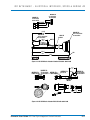
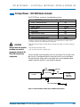
will act as a CAN Master allowing the address. Next, CAN connections are made
between actuator #1, actuator #2, and so on in daisy-chain fashion until the last
actuator is addressed. The last and first actuator must have the 120 Ohm resistor
between the “CAN_H” and “CAN_L” signals to act as a line-terminator. Then, the
CAN addresses of the actuators downstream from actuator #1 are set to unique
numbers, other than “0”.
When ASCII data is exchanged over the serial port, the commands are now
preceded with the node address of the actuator. Actuator #1 converts the data into
CAN data which is then sent to all of the actuators in the chain. All actuators in the
chain appear to be connected to a single RS-232 port in the computer, hence the
reference to multi-drop RS-232.
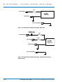
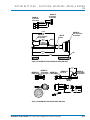
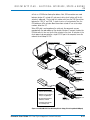
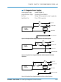
Multi-Drop RS-232 (RS-232 to CANopen)
Power Cable (To Power Source)
Std.: 3604-1641
IP65: 3604-1649
PO SUP
WE PL
R S IED
OU
RC
E
Signal I/O Cable (To RS-232 Port)
Std.: 3604-1640
IP65: 3604-1648
CAN IN
ACTUATOR #1
CAN MASTER
CAN Address = 0
(required)
CAN OUT
POW SUPPL
ER S IED
OUR
CE
CAN IN
CAN OUT
CAN IN
MULTI-DROP RS-232 RULES
• Actuator #1 must have CAN address 0
• All actuators must have different
CAN addresses in network
Communication Cable
1m: 3604-1959
5m: 3604-1660
ACTUATOR #2
CAN Node
CAN Address = 1
(optional)
POW SUPPL
ER S IED
OUR
CE
• CAN address can be saved in flash
memory or set by digital inputs
Terminator
Male: 3604-1653
Female: 3604-1654
CAN OUT
Terminator
Male: 3604-1653
Female: 3604-1654
Communication Cable
1m: 3604-1959
5m: 3604-1660
ACTUATOR #3
CAN Node
CAN Address = 2
(optional)
• Last and first actuator must have
120 Ω terminating resistor
Figure 3-22: ICR/ICM SV1P Plus Multi-drop RS-232 Setup (RS-232 to optional CANopen)
Tolomatic User Guide: ICR Rod Style Integrated Control Actuator 3-13