1
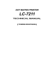
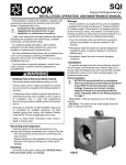
®
Propeller Wall Fans
Installalation, Operation, And Maintenance Manual
Carefully read this publication and any
supplemental documents prior to any
installation or maintenance procedure.
This installation manual provides information for
installing and configuring the Loren Cook Company
Propeller Wall Fans.
• XWD
• APD
• XWHD
• APB
• XPD
• EWD
• XPHD
• EWB
• XLW / XMW
• EPD
• XLWH / XMWH
• EPB
• XLP / XLPH
• SWD
• XMP / XMPH
• SPB
• AWD
• SPD
• AWB
Exhaust & supply models
Loren Cook Company’s Propeller Wall catalog provides
additional information describing the equipment, fan
performance, available accessories and specification data.
For information and instructions on special equipment,
contact Loren Cook Company.
For additional safety information, refer to AMCA
publication 410-96, Safety Practices for Users and
Installers of Industrial and Commercial Fans. This
document and all Cook publications may be obtained from
Cook by phoning (417) 869-6474, extension 166; by FAX
at (417) 832-9431; or by e-mail at [email protected].
All Cook publications are available on LorenCook.com.
Receiving and Inspection
Carefully inspect the unit and accessories for any
damage and shortage immediately upon receipt of the unit.
• Turn the propeller by hand to ensure it turns freely and
does not bind.
• Record on the Delivery Receipt any visible sign of
damage.
Handling
Lift propeller wall fans by attachment to the power
assembly or by the shipping carton. Never lift by the shaft,
motor or housing.
Storage
If the fan is stored for any length of time prior
to installation, coat the shaft with grease or a rust
preventative compound. Store it in its original shipping
crate and protect it from dust, debris and the weather.
Rotate the wheel several revolutions every three to five
days to keep a coating of grease on all internal bearing
parts.
XLWH shown
Rotating Parts & Electrical Shock Hazard
Disconnect electric power before working on unit.
Installation
Follow proper lockout / tagout procedures to ensure
the unit cannot be energized while being installed or
serviced.
Fans mounted to a wall require a different wall opening
size than fans mounted in wall collars or wall housings. For
specific dimensions, refer to the submittal drawing for the
specific fan type.
A disconnect switch should be placed near the fan
in order that the power can be swiftly cut off, in case
of an emergency and in order that maintenance
personnel are provided complete control of the
power source.
Motor Installation
To prevent damage to the fan during shipping, motors 5
HP and larger, and extremely heavy motors (cast iron or
severe duty) are shipped loose and must be field mounted
by bolting the motor on the motor mounting plate in the
existing slots.
The motor should be mounted in order that the motor
plate is between the fan shaft and the motor shaft.
1. Remove the motor plate mounting bolts and motor
plate.
Grounding is required. All field-installed wiring
must be completed by qualified personnel. All field
installed wiring must comply with National Electric
Code (NFPA 70) and all applicable local codes.
Failure to follow these instructions could result in
death or serious injury.
1
2.
3.
4.
Remove the motor mounting bolts from the motor
plate.
Mount the motor to the motor plate aligning the
appropriate holes.
Place the motor plate on the power assembly and
reinstall the mounting bolts.
setscrew and by moving the motor pulley on the motor
shaft.
The drawing below indicates where to measure the
allowable gap for the drive alignment tolerance. All
contact points (indicated by WXYZ) are to have a gap
less than the tolerance shown in the table. When the
pulleys are not the same width, the allowable gap must
be adjusted by half of the difference in width. Figure
3 illustrates using a carpenter’s square to adjust the
position of the motor pulley until the belt is parallel to the
longer leg of the square.
Belt and Pulley
Installation
Belt tension is determined
by the sound of the belts
1/4 inch
when the fan is first started.
The belts will produce a loud
squeal, which dissipates
after the fan is operating at
full capacity. If belt tension
is too tight or too loose, lost
efficiency and damage can
occur.
Do not change the pulley
pitch diameter to change tension. The change will result
in a different fan speed.
1. Loosen the motor plate
adjustment nuts on motor
base and move motor plate
in order that the belts can
easily slip into the grooves
on the pulleys. Never pry,
roll, or force the belts over
the rim of the pulley.
2. Adjust the motor plate until
proper tension is reached.
For proper tension, a
deflection of approximately
1/4” per foot of center
distance should be
obtained by firmly pressing
Figure 3
the belt. See drawing to the
right.
3. Lock the motor plate adjustment nuts in place.
4. Ensure pulleys are properly
Tolerance
aligned. See next section.
1
fo
o
t
Installation
Pulley Alignment
Pulley alignment is adjusted
by loosening the motor pulley
OFFSET
ANGULAR
Center Distance
Maximum
Gap
Up thru 12”
12” up through 48
Over 48”
1/16”
1/8”
1/4”
Insert the fan into the wall opening and secure with lag
screws, anchor bolts, or other suitable fasteners.
Always mount belt drive wall fans in order that the
motor base is below the fan shaft.
Wiring
Proper Electrical Safety Habits
Correctly label the circuit on the main power box and
always identify a closed switch to promote safety
(i.e., red tape over a closed switch).
All wiring should be in accordance with local
ordinances and the National Electrical Code,
NFPA 70. Ensure the power supply (voltage,
frequency, and current carrying capacity
of wires) is in accordance with the motor
nameplate. Follow the wiring diagram in the
disconnect switch and the wiring diagram
provided with the motor.
Leave enough slack in the wiring to allow for motor
movement when adjusting belt tension. Some fractional
motors have to be removed in order to make the
connection with the terminal box at the end of the motor.
Wall Fans
1.
2.
Extend wires to the fan.
Prevent excess wire from entering the shaft and
propeller area by restraining the excess wire to a
point outside the base.
Wall Fans with Wire Guard
1.
OFFSET/ANGULAR
2.
A
W
3.
Remove end panel from the wire guard to gain
access to the motor.
Extend wires through a side panel of the wire guard
to gain access to the motor.
Prevent excess wire from entering the shaft and
propeller area by restraining the excess wire to a
point outside the base.
Wall Fans with Wall Housing
1.
2.
CENTER
DISTANCE
X
(CD)
Y
3.
Z
B
GAP
GAP
2
Remove end guard from the wall housing.
Drill a hole through either side panel at a
convenient location and pull the wires through. Do
not pull wires through wire guard at the back panel.
Restrain the incoming wire at the side panel to
prevent excess wire from entering the shaft and
propeller area.
Single Speed, Single Phase Motor
3 Phase, 9 Lead Motor Y-Connection
3 Phase, 9 Lead Motor
Y-Connection
Ground A
L1
T-1
Low Voltage
208/230 Volts
Line
T-4
L2
4 5 6
7 8 9
Ground B
1
7
When ground is required, attach to ground A or B with
no. 6 thread forming screw. To reverse, interchange
T-1 and T-4.
Low Voltage
208/230 Volts
9
8
7
5
4
6
3
2
1
Low Speed
When ground required, attach to ground A or B with
No. 6 thread forming screw. To reverse, interchange
T-1 and T-4 leads.
L1
L1
Link B
J-10
L2
Line
Low Voltage
L2
Link A & B
T-5
L1
Line
J-10
Motor
L2
Ground B
Ground B
L3
High Voltage
460 Volts
7 8 9
4 5 6
1 2 3
L1 L2 L3
2 Speed, 1 Winding, 3 Phase Motor
Ground A
Link A
T-5
L1 L2 L3
To reverse, interchange any 2 line leads.
Single Speed, Single Phase, Dual Voltage
Ground A
3
3 Phase, 9 Lead Motor
Delta-Connection
L1
Line
L2
Ground B
1 2
3 Phase, 9 Lead Motor Delta-Connection
High Speed
T-1
T-4
2 3
8 9
L1 L2 L3
To reverse, interchange any 2 line leads.
2 Speed, 2 Winding, Single Phase Motor
Ground A
High Voltage
460 Volts
4 5 6
High Speed
1
Together
2
3
4
5
6
L1
L2 Line
L3
Low Speed
L1
1
L2 Line
2
3
L3
Motor
4
Open
5
6
To reverse, interchange any 2 line leads. Motors
require magnetic control.
When ground required, attach to ground A or B with
No. 6 thread forming screw. To reverse, interchange
T-5 and J-10 leads.
2 Speed, 2 Winding, 3 Phase
Typical Damper Motor Schematic
L3
L2
L1
Fan
Motor
Transformer**
Damper
Motor*
Transformer**
To reverse: High Speed-interchange leads T11 and
T12.
Low Speed-interchange leads T1 and T2. Both
Speeds-interchange any 2 line leads.
Second
Damper
Motor
For 3 phase, damper motor voltage should be
the same between L1 and L2. For single phase
application, disregard L3. *Damper motors may be
available in 115, 230 and 460 volt models. The damper
motor nameplate voltage should be verified prior to
connection. **A transformer may be provided in some
installations to correct the damper motor voltage to the
specified voltage.
3
Shutters
•
•
•
•
•
Direction of rotation.
Excessive vibration.
Unusual noise.
Bearing noise.
Improper belt alignment or tension (listen for a
continuous squealing noise).
• Improper motor amperage or voltage.
NOTICE! If a problem is discovered, immediately
shut off the fan. Lock out all electrical power
and check for the cause of the trouble. Refer to
Troubleshooting
If your fan is supplied with a shutter, follow the direction
below. If your fan is not supplied with a shutter, proceed
to Final Installation Steps.
To ensure long-life, make a weather-proof seal by using
a good quality silicon caulking under the shutter flange.
1. Place the shutter into the wall opening.
2. Mount the shutter to the supporting surface using
Number 12 sheet metal screws on six inch centers
around the perimeter.
3. Manually operate the shutter to ensure the blades
move freely.
Recommended Torque for Setscrews/Bolts
Typical Installation
In. - Lb.
Refer to page 8.
Setscrews
Final Installation Steps
1.
2.
3.
4.
Inspect fasteners and setscrews, particularly
fan mounting and bearing fasteners, and tighten
according to the recommended torque shown in
the table on page 4, Recommended Torque for
Setscrews/Bolts.
Inspect for correct voltage with voltmeter.
Ensure all accessories are installed.
Test the fan to be sure the rotation is the same as
indicated by the arrow marked Rotation.
Key Hex
Across
Flats
Recommended
Torque
Min.
Max.
Size
Wrench
Torque
No.10
3/32”
28
33
3/8”-16
240
1/4”
1/8”
66
80
1/2”-13
600
5/16”
5/32”
126
156
5/8”-11
1200
3/8”
3/16”
228
275
3/4”-10
2100
7/16”
7/32”
348
384
7/8”-9
2040
1/2”
1/4”
504
600
1”-8
3000
5/8”
5/16”
1104
1200
1-1/8”-7
4200
3/4”
3/8”
1440
1800
1-1/4”-7
6000
Size
Proper Rotation
Do not allow the fan to run in the wrong direction.
This will overheat the motor and cause serious
damage. For 3-phase motors, if the fan is running
in the wrong direction, check the control switch. It is
possible to interchange two leads at this location so
that the fan is operating in the correct direction.
Hold Down Bolts
Recommended
Torque
Inspection
Inspection of the fan should be conducted at the first
30 minute, 8 hour and 24 hour intervals of satisfactory
operation. During the inspections, stop the fan and
inspect as per directions below.
30 Minute Interval
Operation
Inspect bolts, setscrews, and motor mounting bolts.
Adjust and tighten as necessary.
Pre-Start Checks
8 Hour Interval
1.
Lock out all the primary and secondary power
sources.
2. nspect fasteners and setscrews, particularly
those used for mounting the unit, and tighten if
necessary.
3. Inspect belt tension and pulley alignment.
(Remember, if belt tension is correct, a loud squeal
occurs as the fan increases to full power.)
4. Inspect motor wiring.
5. Ensure the belt touches only the pulleys.
6. Rotate the prop to ensure it does not rub against
the venturi.
7. Ensure fan and ductwork are clean and free of
debris.
8. Test the fan to ensure the rotation of the propeller
is the same as indicated by the rotation label.
9. Close and secure all access doors.
10. Restore power to unit.
Inspect belt alignment and tension. Adjust and tighten
as necessary.
24 Hour Interval
Inspect belt tension. Adjust and tighten as necessary.
Maintenance
Establish a schedule for inspecting all parts of the fan.
The frequency of inspection depends on the operating
conditions and location of the fan.
Inspect fans exhausting corrosive or contaminated
air within the first month of operation. Fans exhausting
contaminated air (airborne abrasives) should be
inspected every three months. Clean the propeller and air
inlets if material build-up is excessive. Excessive build-up
can cause imbalance and failure of the propeller. Regular
inspections are recommended for fans exhausting
non-contaminated air. It is recommended the following
inspections be conducted twice per year.
• Inspect bolts and setscrews for tightness. Tighten as
necessary.
Start Up
Turn the fan on. In variable speed units, set the fan to
its lowest speed. Inspect for the following:
4
• Inspect belt wear and alignment. Replace worn belts
with new belts and adjust alignment as needed. See Belt
and Pulley Installation, on page 2.
• Bearings should be inspected as recommended in the
Conditions Chart, below.
• Inspect for cleanliness. Clean exterior surfaces only.
Removing dust and grease on motor housing assures
proper motor cooling.
The above intervals should be reduced to half for vertical
shaft installations.
Fan Bearings
The fan bearings are provided prelubricated. Any
specialized lubrication instructions on fan labels
supersedes information provided herein. Bearing grease
is a petroleum lubricant in a lithium base conforming to a
NLGI #2 consistency. If user desires to utilize another type
of lubricant, they take responsibility for flushing bearings
and lines, and maintaining a lubricant that is compatible
with the installation.
A NLGI #2 grease is a light viscosity, low-torque, rustinhibiting lubricant that is water resistant. Its temperature
range is from -30°F to 200°F and capable of intermittent
highs of 250°F.
Bearings should be relubricated in accordance with the
condition chart below.
For best results, lubricate the bearing while the fan is in
operation. Pump grease in slowly until a slight bead forms
around the bearing seals. Excessive grease can damage
seal and reduce life through excess contamination and/or
loss of lubricant.
In the event that the bearing cannot be seen, use no
more than three injections with a hand operated grease
gun.
Lubricants
Loren Cook Company uses petroleum lubricant in a
lithium base conforming to NLGI grade 2 consistency.
Other grades of grease should not be used unless the
bearings and lines have been flushed clean. If another
grade of grease is used, it should be lithium-based.
A NLGI grade 2 grease is a light viscosity, lowtorque, rust-inhibiting lubricant that is water resistant. Its
temperature range is from -30°F to +200°F and capable of
intermittent highs of +250°F.
Motor Bearings
Motors are provided with prelubricated bearings. Any
lubrication instructions shown on the motor nameplate
supersede instructions below.
Direct Drive 1050/1075,1200,1300 &1500 rpm units use
a prelubricated sleeve bearing that has a oil saturated
wicking material surrounding it. The initial factory
lubrication is adequate for up to 10 years of operation
under normal conditions. However, it is advisable to add
lubricant after 3 years. Use only LIGHT grade mineral oil
or SAE 10W oil up to 30 drops. If the unit has been stored
for a year or more it is advisable to lubricate as directed
above. For units in severe conditions, lubrication intervals
should be reduced to half.
Motors without sleeve bearings (as described above)
will have grease lubricated ball or roller bearings. Motor
bearings without provisions for relubrication will operate up
to 10 years under normal conditions with no maintenance.
In severe applications, high temperatures or excessive
contaminates, it is advisable to have the maintenance
department disassemble and lubricate the bearings after 3
years of operation to prevent interruption of service.
For motors with provisions for relubrication, follow
intervals of the table below.
Conditions Chart
RPM
Up to 1000
1800
RPM
and
less
Over
1800
RPM
1800
RPM
and
less
Over
1800
RPM
Standard
3 yrs.
6
months
2 yrs.
6
months
1 yr.
3
months
Severe
Service
Conditions
Over
1800
RPM
1 yr.
3
months
1 yr.
3
months
6
months
1
months
6 months
120 to 200
2 months
3 months
1 month
-30 to 120
1 month
120 to 200
2 weeks
Any Speed
< -30
Consult Factory
Any Speed
> 200
1 week
For moist or otherwise contaminated installations;
divide the interval by a factor of 3. For vertical shaft
installations divide the interval by a factor of 2.
Motor Services
Should the motor prove defective within a one-year
period, contact your local Loren Cook representative
or your nearest authorized electric motor service
representative.
404T and larger
1800
RPM
and
less
-30 to 120
-30 to 120
Over 3000
NEMA Frame Size
213T-365T
Greasing Interval
120 to 200
1000 to
3000
Relubrication Intervals
Up to and
including 184T
Temp °F
Changing Shaft Speed
All belt driven Propeller Wall fans with motors up to and
including 5HP are equipped with variable pitch pulleys. To
change the fan speed, perform the following:
a. Loosen setscrew on driver (motor) pulley and remove key, if equipped.
b. Turn the pulley rim to open or close the groove facing.
If the pulley has multiple grooves, all must be adjusted to
the same width.
c. After adjustment, inspect for proper belt tension.
Speed Reduction
Motors are provided with a polyurea mineral oil NGLI #2
grease. All additions to the motor bearings are to be with a
compatable grease such as Exxon Mobil Polyrex EM and
Chevron SRI.
Open the pulley in order that the belt rides deeper in the
groove (smaller pitch diameter).
5
Speed Increase
Close the pulley in order that the belt rides higher in the
groove (larger pitch diameter). Ensure that the RPM limits
of the fan and the horsepower limits of the motor are
maintained.
XMW/
XMWHS
Size
Maximum
RPM
XMWH/
XMWHS
Size
Maximum
RPM
20
1462
-
-
24
1272
24
1385
30
860
30
1175
Maximum RPM
EWB
Size
Maximum
RPM
AWB
Size
Maximum
RPM
APB
Size
Maximum
RPM
36
672
36
948
24
1675
24
1510
24
1005
42
498
42
829
30
1370
30
1145
30
800
48
416
48
726
36
1310
36
990
36
645
54
350
54
522
42
1175
42
905
42
660
60
320
60
530
48
1215
48
900
48
605
54
960
-
-
-
-
60
890
-
-
-
-
1.
2.
72
700
-
-
-
-
3.
XLP/
XLPS
Size
Maximum
RPM
XLPH/
XLPHS
Size
Maximum
RPM
20
1280
-
-
24
1012
24
1100
30
666
30
1074
36
566
36
895
42
424
42
870
48
356
48
761
54
316
54
472
60
260
60
446
XMP/
XMPS
Size
Maximum
RPM
XMPH/
XMPHS
Size
Maximum
RPM
20
1280
-
-
24
1276
24
1385
30
830
30
1175
36
680
36
948
42
498
42
829
48
414
48
726
54
346
54
522
60
318
60
530
XLW/
XLWS
Size
Maximum
RPM
XLWH/
XLWHS
Size
Maximum
RPM
20
1276
-
-
24
1018
24
1126
30
674
30
1074
36
570
36
895
42
422
42
870
48
356
48
761
54
320
54
478
60
256
60
438
Pulley and Belt Replacement
4.
5.
6.
7.
8.
Clean the motor and fan shafts.
Loosen the motor plate mounting bolts to relieve
the belt tension. Remove the belt.
Loosen the pulley setscrews and remove the
pulleys from the shaft. NOTICE! If excessive force
is required to remove the pulleys, a threejaw puller can be used. This tool, however,
can easily warp a pulley. If the puller is used,
inspect the trueness of the pulley after it is
removed from the shaft. The pulley will need
replacement if it is more than 0.020 inch out of
true.
Clean the bores of the pulleys and place a light
coat of oil on the bores.
Remove grease, rust and burrs from the shaft.
Place fan pulley on the fan shaft and the motor
pulley on the motor shaft. Damage to the pulleys
can occur when excessive force is used in placing
the pulleys on their respective shafts.
After the pulleys have been correctly placed back
onto their shafts, tighten the pulley setscrews.
Install the belts on the pulleys. Align and adjust the
belts to the proper tension as described in Belt and
Pulley Installation, page 2
Bearing Replacement
6
The fan bearings are pillow block ball bearings.
1. Mark the position of the shaft in reference to both
the bearing races and the propeller and pulley.
Make a note of the clearance between the propeller
and the frame.
2. Remove the pulley.
3. Remove the propeller from the shaft. A two-jaw
puller may be needed to remove the propeller from
the shaft.
4. Remove the bearing hold-down bolts. Remove the
shaft and the bearings as one unit.
5. Remove the anti-corrosion coating from the shaft
with a suitable degreaser.
6. Remove the bearing from the shaft using a bearing
puller. If a bearing puller is not available, remove
the bearing by using a wood block and hammer.
An emery cloth or file may be needed to remove
imperfections in the shaft left by the setscrews.
7. Clean the shaft and bearing bore thoroughly.
8. Place the bearings into position ensuring they are
not on a worn section of the shaft. Tapping the
9.
10.
11.
12.
13.
14.
15.
16.
17.
18.
19.
20.
inner ring face with a soft driver may be required. Do
not hammer on the housing.
The outer ring of the bearing is spherical and
swivels in the housing to compensate for
misalignment. Slightly tighten the hold down bolts.
Align the setscrews on the bearings and tighten one
setscrew on each bearing.
Rotate the shaft to allow the bearing outer rings to
find the center of free movement.
Install the propeller on the shaft and adjust the
bearing position to center the propeller in the
opening.
Tighten the hold-down bolts to the proper torque.
Refer to the Torque Chart, page 4.
Turn the shaft by hand. Resistance should be the
same as it was before the hold-down bolts were fully
tightened.
Tighten the bearing setscrews to the specified
torque.
Install the pulley and adjust the belt tension.
After 24 hours of continuous operation, tighten the
setscrews to the appropriate torque. This assures
the full locking of the inner race to the shaft. Ensure
the socket key or driver is in good condition with no
rounded corners. The key should be fully engaged
in the setscrew and held squarely to prevent the
rounding out of the setscrew socket when applying
maximum torque.
• Incorrect direction of rotation. Make sure the fan
rotates in same direction as the arrows on the motor
or belt drive assembly.
• Cooling air diverted or blocked.
• Improper inlet clearance.
• Incorrect fan RPMs.
• Incorrect voltage.
• Overheated Bearings
• Improper bearing lubrication
• Excessive belt tension.
Typical Installations (Dimensions are in inches)
Exhaust fan with OSHA wire guard & shutter
Illustrated is the typical installation of an exhaust wall fan
with an OSHA wire guard and shutter in a steel structure
with corrugated siding. The installer will provide a sleeve
of suitable material to support the fan at a correct distance
from the shutter (minimum distance is the “A” dimension).
B
C
WO
D
A
1-1/2
1-1/2
Fan support and flashing by others.
Troubleshooting
Problem and Potential Cause
Low Capacity or Pressure
• Incorrect direction of rotation. Make sure the fan
rotates in same direction as the arrows on the motor
or belt drive assembly.
• Poor fan inlet conditions. There should be a straight
clear duct at the inlet.
• Improper propeller alignment.
Excessive Vibration and Noise
•
•
•
•
Damaged or unbalanced propeller.
Belts too loose; worn or oily belts.
Speed too high.
Incorrect direction of rotation. Make sure the fan
rotates in same direction as the arrows on the motor or
belt drive assembly.
• Bearings need lubrication or replacement.
• Fan surge.
Overheated Motor
• Motor improperly wired.
7
WO
AWB
AWD
SWD
XLW
XLWH
XMW
XMWH
EWB
EWD
A
B
C
D
E
Std.
Fan
Wire
Guard.
8
-
-
11
13
12-3/4
10
1
12-1/2
13-1/4
1012
-
-
12
13
16-3/4
14
1
16-7/16
17-1/4
1416
-
-
12
13
20-3/4
18
1
20-7/16
21-1/4
1820
-
-
13
12
24-3/4
22
1
24-7/16
25-1/4
-
20
-
13
21
24-3/4
22
1
24-7/16
25-1/4
24
-
-
15
21
30-3/4
27
1-1/2
30-7/16
31-1/4
-
24
-
15
13
30-3/4
27
1-1/2
30-7/16
31-1/4
30
30
24
16
21
36-3/4
33
1-1/2
36-7/16
37-1/4
36
36
30
16
21
42-3/4
39
1-1/2
42-7/16
43-1/4
42
42
36
17
26
48-7/8
45
1-1/2
48-7/16
49-1/4
48
48
42
17
26
54-7/8
51
1-1/2
54-7/16
55-5/16
-
54
48
17
28
60-7/8
57
1-1/2
60-7/16
61-5/16
-
60
54
17
28
66-7/8
63
1-1/2
66-7/16
67-1/2
-
-
60
17
28
72-7/8
69
1-1/2
72-7/16
73-1/2
-
-
72
17
31
84-7/8
81
1-1/2
84-7/16
85-1/2
Exhaust package fan with shutter guard
Supply fan with wall collar, OSHA wire
guard, motorized supply shutter & weather
hood
Illustrated is the typical installation of an exhaust PACFan in a masonry wall with a shutter guard. The installer
provides suitable fasteners (Hex bolts or Lag screws) to
support the fan. It is recommended that 5/16” minimum
bolts on 6” to 10” centers be used on the perimeter of the
housing. Mounting flange should be caulked to exterior of
the wall. Fans with motors in excess of 80 lbs. should be
additionally supported by hanging rods or supports placed
underneath the fan.
Illustrated is the typical installation of a supply wall fan
in a masonry wall with a wall collar, OSHA wire guard,
motorized supply shutter and weather hood. The installer
provides suitable fasteners to support the fan. Fasteners
should be placed on 6” to 10 centers on the perimeter
of the wall collar. Wall collar should be caulked to the
exterior of the wall. The weather hood should be securely
fastened and sealed to the wall. Fans with motors in
excess of 80 lbs. should be additionally supported by
hanging rods or supports placed underneath the fan.
D
E
C
Ar
ea
A
WO
A
Ho
od
Fr
ee
WO
7
B
B
APB,
APD,
SPD
XLP,
XLPH,
XMP,
XMPH
EPB,
EPD
A
BDirect
B-Belt
WO
8
-
-
10-5/8
13-5/8
-
13-1/4
10-12
-
-
14-5/8
17-5/8
-
17-1/4
14-16
-
-
18-5/8
20
-
21-1/4
18-20
20
-
22-5/8
22
34-1/4
25-1/4
24
24
-
27-7/8
23
34-1/4
31-1/4
30
30
24
33-7/8
24-3/8
37-7/8
37-1/4
36
36
30
39-7/8
28-3/8
39-3/8
43-1/4
42
42
36
45-7/8
33-5/8
40-5/8
49-1/4
48
48
42
51-7/8
39-5/8
50-5/8
55-5/16
-
54
48
57-7/8
40-1/8
47-3/4
61-5/16
-
60
54
63-7/8
44-3/4
47-3/4
67-1/2
-
-
60
69-7/8
-
47-3/4
73-1/2
-
-
72
81-7/8
-
50-3/4
85-1/2
8
AWB
AWD
SWD
XLW
XLWH
XMW
XMWH
EWB
EWD
A
B
C
D
E
WO
8
-
-
18
16
12
13
1
13-1/4
1012
-
-
22
18-3/4
14-3/8
13
1
17-1/4
1416
-
-
26
21-3/4
15-3/8
13
1
21-1/4
1820
-
-
30
24-1/2
17-5/8
13
1
25-1/4
-
20
-
30
24-1/2
17-5/8
21
1
25-1/4
24
-
-
30
24-1/2
17-5/8
13
1-1/2
31-1/4
-
24
-
34
27-1/4
18-3/4
21
1-1/2
31-1/4
30
30
24
40
31-1/2
18-3/4
21
1-1/2
37-1/4
36
36
30
46
35-3/4
19-1/2
21
1-1/2
43-1/4
42
42
36
52
40
19-1/2
26
1-1/2
49-1/4
48
48
42
58
44-1/4
19-3/4
26
1-1/2
55-5/16
-
54
48
64
48-1/2
19-3/4
28
1-1/2
61-5/16
-
60
54
70
52-3/4
19-3/4
28
1-1/2
67-1/2
-
-
60
76
57
19-3/4
28
1-1/2
73-1/2
-
-
72
88
67-1/2
19-3/4
31
1-1/2
85-1/2
Parts List
XWD & SWD
XPD & SPD
Exhaust
3
2
4
1
Exhaust
6
5
9
3
2
10
11
9
3
6
10
11
2
Air Flow
1
1
5
Air
Flow
5
Rotation
Supply
4
3
2
4
5
Air
Flow
4
XPHD
Exhaust
1
Size 12-18
6
2
9
3
Size 20-24
10
11
6
9
3
2
10
11
Air Flow
Rotation
1
8
7
Description
Part
Description
1
Motor
5
Stamped Aluminum Propeller
2
Wire Guard
6
Wall Collar
3
Wall Base
7
End Wire Guard
4
Venturi
Air
Flow
Size 12-18
Exhaust
Supply
Size 12-18
6
2
4
1
7
1
8
1
7
Air Flow
6
9
3
Size 20-24
10
11
6
7
Air Flow
6
1
8
5
11
Air
Flow
4
Description
XPD SPD
1
2
4
7
XPHD
Motor
Wire Guard
Power Assembly
Description
1
Motor
2
Power Assembly
3
Wall Base
4
Venturi
5
Stamped
Aluminum
Propeller
6
End Wire Guard
9
Mounting Collar Angles (4)
7
Motor Plate
10
Anchor Angles (2)
11
Shutter Assembly
Size 20-24
Exhaust
Supply
4
4
1
7
1
7
Air Flow
10
5
Part
Note: Since 2012, the
venturi and base are
6
one piece.
9
3
2
Air
Flow
Part
3
4
7
4
Supply
4
Exhaust Rotation
Air
Flow
7
Note: Since 2012, the venturi and base are one piece.
2
5
Supply Rotation
5
6
Part
XWHD
1
8
5
6
3
Wall Base
4
Venturi
5
Stamped Aluminum Propeller
6
Fan Box Panels
7
8
End Wire Guard
-
Motor Plate
Note: Since 2012, the venturi and base are one piece.
Air Flow
9
XLW / XMW
Exhaust
2
4
3
9
11
5
Supply
2
6
8
10
9
13
7
4
3
5
9
11
8
10
13
Rotation
13
7
XLWH / XMWH
Exhaust
2
3
5
11
1
10
Rotation
8
13
Supply
2 3
7
Air Flow
4
5
11
1
6
9
12
12
6
9
10 13
Rotation
6
7
3
Air Flow
11
12
14
5
2
6
7
3
Air Flow
Part
Description
1
Base
2
Prop
3
Venturi
4
Shaft
5
Bearings (2)
6
Motor
7
Motor Plate
8
Driven Sheave
9
Drive Sheave
10
Belt
11
Mounting Collar
Angles (4)
12
Anchor Angles (2)
13
End Wire Guard
14
Shutters
Note: Since 2012, the
venturi and base are one
piece.
Air Flow
4
2
4
8
10
9
12
5
4
1
6
11
14
Supply
Air Flow
12
1
1
8
10
13
Rotation
Exhaust
Air Flow
12
1
XLP / XLPH / XMP / XMPH
8
7
Part
Description
Part
Description
1
Power Assembly Rail
8
Motor
2
Base
9
Motor Plate
3
Prop
10
Drive Sheave
4
Power Assembly Feet (3)
11
Driven Sheave
5
Shaft
12
Belt
6
Bearings (2)
13
End Wire Guard
7
Venturi
Note: Since 2012, the venturi and base are one piece.
10
AWD
APD
Exhaust
1
Exhaust
2
3
1
4
8
3
2
9
10
Air
Flow
5
6
5
Rotation
Supply
1
2
7
Air Flow
3
4
Rotation
Supply
1
Part
Description
1
Power Assembly
2
Prop
3
Base
4
Venturi
5
Motor
AWB
6
Motor Plate
Exhaust
7
Wire Guard
8
Shaft
9
Bearings
10
Driver Sheave
11
Belt
12
Driven Sheave
5
6
Rotation
1
2
Air Flow
7
3
Air Flow
8
11
12
10
4
9
5
Rotation
Supply
1
2
Air Flow
3
8
11
12
10
Rotation
8
3
2
9
10
5
6
7
Rotation
4
APB
Exhaust
3
1
7
7
6
9
6
4
Air
Flow
8
9
10
15 14
12
13
11
2
3
1
10
5
4
Supply
9
8
15 14
12
13
11
5
7
4
Air
Flow
Note: Since 2012, the
venturi and base are
one piece.
6
7
6
7
2
5
6
4
Air
Flow
Part
Description
1
Power Assembly
10
Shutters
2
Prop
11
Driven Sheave
3
Base
12
Driver Sheave
4
Venturi
13
Belt
5
Motor
14
Shaft
6
Motor Plate
15
Bearings
7
Wire Guard
8
Mounting Collar Angles (4)
9
Anchor Angles (2)
Description
Note: Since 2012, the venturi and base are one piece.
11
EWD
Exhaust Rotation
1
4
2
3
Exhuast
Air
Flow
5
6
Supply
Air
Flow
7
Supply Rotation
EWB
Exhaust Rotation
1
4
3
2
9
Exhuast
Air
Flow
8
12
11
10
Supply
Air
Flow
5 6
7
Supply Rotation
EPD
Exhaust
3
13 1
4
5
6
2
5
Supply
3
Air
Flow
5
6
6
7
7
4
EPB
Exhaust
13
1
Air
Flow
3
14 15
16
8
9
2
12
11
10
7
14 15
16
Air
2 Flow
13 1
4
Supply
3
13
1
Air
Flow
8
9
14 15
16
2
12
11
10
5
6
4
7
5
6
4
Part
Description
Description
v
Power Assembly
10
Driver Sheave
2
Prop
11
Belt
3
Base
12
Driven Sheave
4
Venturi
13
Fan Box Panels
5
Motor
14
Mounting Collar
Angles (4)
6
Motor plate
15
Anchor Angles (2)
7
End Wire Guard
16
Shutters
8
Bearing
9
Shaft
Note: Since 2012, the
venturi and base are one
piece.
12
Weather Hood Size 36 to 60
Weather Hood Size 8 to 30
6
8
1
3
1
2
4
3
8
2
7
6
9
5
5
8
7
4
8
6
6
Part
Description
Description
1
Top Panel, Piece 1
Part
Description
6
Bird Screen Support
1
Top Panel
5
1/2” Mesh Galvanized Bird Screen
2
3
Top Panel, Piece 2
7
1/2” Mesh Galvanized Bird Screen
2
Right Side Panel
6
1/4” X 1/2” Speed Screw
Right Side Panel
8
1/4” X 1/2” Speed Screw
3
Left Side Panel
7
5/16 SAE Steel Washer
4
Left Side Panel
9
5/16 SAE Steel Washer
4
Bottom Panel
5
Bottom Panel
13
Description
Weather Hood EWB 72
1
10
10
2
10
3
6
9
8
4
11
7
10
10
Part
Description
Part
Description
1
Top Panel, Piece 1
7
Bottom Panel
2
Top Panel, Piece 2
8
Bird Screen Support
3
Right Side Panel Tip
9
1/2” Mesh Galvanized Bird Screen
4
Right Side Panel
10
1/4” X 1/2” Speed Screw
5
Left Side Panel Tip
11
5/16 SAE Steel Washer
6
Left Side Panel
14
Limited Warranty
Loren Cook Company warrants that your Loren Cook
fan was manufactured free of defects in materials and
workmanship, to the extent stated herein. For a period of
one (1) year after date of shipment, we will replace any
parts found to be defective without charge, except for
shipping costs which will be paid by you.
This warranty is granted only to the original purchaser
placing the fan in service.
This warranty is void if the fan or any part thereof has
been altered or modified from its original design or has been
abused, misused, damaged or is in worn condition or if the
fan has been used other than for the uses described in the
company manual. This warranty does not cover defects
resulting from normal wear and tear.
To make a warranty claim, notify Loren Cook Company,
General Offices, 2015 East Dale Street, Springfield,
Missouri 65803-4637, explaining in writing, in detail,
your complaint and referring to the specific model and
serial numbers of your fan. Upon receipt by Loren Cook
Company of your written complaint, you will be notified,
within thirty (30) days of our receipt of your complaint,
in writing, as to the manner in which your claim will be
handled. If you are entitled to warranty relief, a warranty
adjustment will be completed within sixty (60) business
days of the receipt of your written complaint by Loren Cook
Company.
This warranty gives only the original purchaser placing
the fan in service specifically the right. You may have other
legal rights which vary from state to state.
For fans provided with motors, the motor manufacturer
warrants motors for a designated period stated in the
manufacturer’s warranty. Warranty periods vary from
manufacturer to manufacturer. Should motors furnished by
Loren Cook Company prove defective during the designated
period, they should be returned to the nearest authorized
motor service station. Loren Cook Company will not be
responsible for any removal or installation costs.
15
Corporate Offices 2015 E. Dale Street Springfield, MO 65803
Phone 417-869-6474 Fax 417-862-3820
lorencook.com
16
Propeller Wal IOM Manual - Oct 2012