1
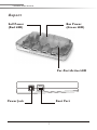
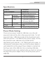
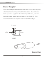
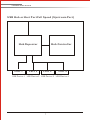
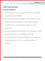
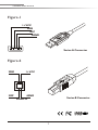
UNIVERSAL
SERIAL BUS HUB
User Manual
UNIVERSAL SERIAL BUS HUB
Please read this manual thoroughly and follow the instruction
procedures to prevent any damage to the USB HUB and or the
connecting devices.
Package Content
s One USB Hub
s One USB Cable (6 feet)
s One Power Adapter DC 5V (2.5A)
Overview
The USB Hub provides the electronic interface between USB
devices and the host. It allows up to three USB devices or Hubs
to connect to an upstream USB Hub or Host port, USB HUB is a
complete USB 1.1 specification compatible device. USB HUB
offers a real plug & play environment to the PC world.
Features
s USB 1.1 specification compatibility
s Plug and play with USB devices
s Bus fault detection and recovery.
s All Downstream Ports support full-speed and low-speed
operations
s Supports Self-Powered mode and Bus-Powered mode, indicate
by power LED
1
UNIVERSAL SERIAL BUS HUB
l Low voltage drop:
1. Self-powered mode:
Max 500mA (indicated by Red power LED)
2. Bus-powered mode:
140mV/500mA, 14mV/50mA (indicated by Green
power LED)
l Individual power switches (each port):
1. Over-current protection with current limit threshold:
500mA(Min)750mA(Typ)/1250mA(Max)
2. Turn power off in status of over-current or thermal shutdown,
save power consumption
3. Soft start for slow turn-on feature prevents high inrush currents
when initially powering capacitive loads
l Reset by Upstream attachment or programmable reconfigure
l Downstream port LEDs: indicating Power and Active on/off
l Self-powered mode: Shutdown system power no need to
disconnect the power adapter, power consumption only
3mA for Red power LED
l Supports suspend MODE
2
UNIVERSAL SERIAL BUS HUB
Aspect
Self Power
(Red LED)
Bus Power
(Green LED)
Per-Port Active LED
Power Jack
Root Port
3
UNIVERSAL SERIAL BUS HUB
Specifications
Function
Description
Power Consumption
3mA per LED
40mA for HUB control circuit
Connector
LED
Upstream
1 USB Series B Receptacle
Downstream
4 USB Series A Receptacles
Power
1 USB-power (Green LED)
1 Self-power (Red LED)
Port Status
4 Port Active Status (Green LED)
Weight
100g
Dimension (LxWxH)
135mm(L)x72mm(W)x23mm(H)
Power Mode Setting
There are two power modes for USB Hub, one is the selfpowered mode and the other is Bus-powered mode. For selfpowered mode, USB Hub provides all the downstream ports
with each port DC + 5V, 500mA (max.) power supply. For the
Bus-powered mode, USB Hub only provides all four
downstream ports with DC + 5V, 100mA each port in total. In
self-powered mode please make sure that the power adapter is
well installed first and the plug of Power Adapter is inserted into
the Power Jack of the USB Hub, then connecting USB cable.
The powered mode is auto selected while you insert (or remove)
the plug of the power adapter into (or from) the power jack of
USB Hub.
4
UNIVERSAL SERIAL BUS HUB
Power Adapter
The Power Adapter attached with USB Hub is DC 5V, 2.5A (min.)
which is a minimum requirement for the device. If user needs
more power to supply the downstream port devices, user can
purchase a new power with the Spec. of DC 5V, 2.5A. The
mechanical of Power Adapter is listed in the follow figure.
2.1mm
5.5mm
+5V
GND
Power Plug
5
UNIVERSAL SERIAL BUS HUB
Diagram
PC
2 Port Hub
Telephone
Camera
Joystick
Electric Keyboard
6
UNIVERSAL SERIAL BUS HUB
USB Hub or Host Port Full Speed (Upstream Port)
Hub Repeater
Port 1
Port 2
Hub Controller
Port 3
Port 4
USB Device 1 USB Device 2 USB Device 3 USB Device 4
7
UNIVERSAL SERIAL BUS HUB
INSTALLATION
Install the Hardware
A. First of all, please insert the plug of the DC 5V 2.5A power adapter
into the power jack of USB Hub
B. Connect the series-A connector (please refer to the Figure-1) of the
USB cable into the downstream port of PC USB host controller
(or ROOT hub) or one downstream port of the upper level
(parent) hub.
C. Connect the series-B connector (please refer to the Figure-2) of USB
able into the upstream port of USB Hub, the USB hub.
D. Connect the series-A connector of USB device, such as USB mouse,
USB keyboard and so on, into any one of the downstream of
USB Hub.
8
UNIVERSAL SERIAL BUS HUB
Figure-1
1+VCC
2DM
3DP
4GND
Series-A Connector
Figure-2
2DM
1+VCC
3DP
4GND
Socket B
Series-B Connector
9