1
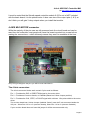
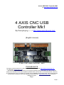
4 Axis USB CNC Controller Mk1
(By http://www.pennybuying.com
)
It must be noted that the Spindle speed controller module 0-5/10v out is NOT included
with the basic board, it is an optional extra. It also uses two of the output pins (1 & 3) so
don't think you will gain 3 relay outputs when you install that module.
4 AXIS Mk1 MOTOR connector
While the majority of the pin uses are silk-screened onto the circuit board and can be
read from the underside, most people will have the board mounted into a case before
making the connections – which obviously means they won't be readable at the time.
Okay let's get straight to the pins you will be most interested in...
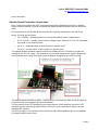
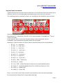
The 4 Axis connectors
The 4 Axis connector blocks each contain 3 pins used as follows:
Pin 1 – Provides the DIR, or DIRECTION signal to the motor driver
Pin 2 – Provides a Common Anode, or Cathode (Based on Yellow Jumper position)
Pin 3 – Provides the CLK, STEP, or PULSE signal with minimum 12us pulse width to the motor
driver
This revision board has a Yellow Jumper (Labelled “Select”) near the Z axis connector beside the
I2C port – Short Pins 2-3 for +5v (common Anode), Short Pins 1-2 for 0v (common Cathode)
If your revision board does not have this jumper it will be common anode only.
Page 6