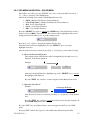
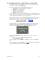
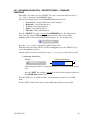
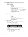
1
Rugged Military ACH4600
Flat Panel Display
User’s Guide
For
ACH4600
Chassis Mount
1. PRODUCT OVERVIEW
This User Guide is for Aydin Displays standard Model 4446 Flat Panel Display with
optional QuadView XL windowing system capable of displaying live video and/or computer
windows on each of four windows. Each window has four inputs of which only one input
can be displayed at a time. The four inputs are as follows:
•
RGB / YPbPr component
•
Composite video
•
S-Video
•
DVI
All of the input sources can be mixed and matched simultaneously, and each input can be
independently scaled, positioned, panned and zoomed.
All QuadView XL functions can be accessed remotely by either RS-232 serial
communications or via network control (Ethernet 10/100 BaseT).
For detailed operation of the QuadView XL, please refer to the QuadView XL Users Guide
contained on the Product CD or the following RGB Spectrum Web site for the latest
revision:
www.rgb.com/en/manuals.asp
With the QuadView XL installed, some of the standard 4446 Display functions, accessible
through the OSD, are disabled. The display functions that are enabled are described in this
User Guide.
2. CONNECTIONS AND SETUP
To connect the LCD display to your system, follow these instructions:
CAUTION: Turn power off to the computer, display, and power supply
before making any connections.
The power ON/OFF switch designations are as follows:
ON
PWR
OFF
Placing the POWER switch in the ‘ON’ position applies power to all of the internal
components of the display and will enable the display.
With the POWER switch in the ‘ON’ position, the display can also be turned ON and OFF
by doing the following:
150-4446-101(-)
4
-
Using the POWER button on the remote control.
Through the host interface.
Using the OSD. Pushing the SELECT button on the front panel when the unit is
OFF will display the OSD, which can then be used to power the unit ON.
2.1 Power Connections
AC operating input voltage is 90-132/180-264 VAC Auto-ranging, 47-63 Hz.
Plug the AC Power Cord into the AC power inlet on the rear of the unit.
NOTE: THE POWER CORD RETENTION BRACKET MUST BE
INSTALLED WITH THE SUPPLIED HARDWARE TO MEET
SHOCK AND VIBRATION.
Connect the AC line power cord to a grounded outlet. For maximum protection, use
a good surge protector between the outlet and the power supply to avoid damage to
the display due to electrical service abnormalities.
2.2 Signal Connections
The desired video input source is selected using one of the QuadView XL Remote
Access interfaces. If the video input connection is different from the Video Source
selection, a ‘No Sync!’ symbol will be displayed, see section 3.1.4.
2.2.1 VGA (YUB) HD15 Signal Connections
The LCD should be connected to a video source using a HD15-male to HD15-male
cable. Pin assignments for the HD15 connector are shown below.
Pin
Signal
Pin
Signal
1
Red Video Signal
(alternative input V)
9
No Connection
2
Green Video Signal
(alternative input Y)
10
Ground
3
Blue Video Signal
(alternative input U)
11
No Connection
4
No Connection
12
No Connection
5
No Connection
13
Horizontal Sync Signal
6
Ground for Red Video Signal
14
Vertical Sync Signal
7
Ground for Green Video Signal
15
No Connection
8
Ground for Blue Video Signal
150-4446-101(-)
5
2.2.2 NTSC Signal Connections
The NTSC inputs use a standard 75-ohm BNC connector.
2.2.3 S-VIDEO Signal Connections
–
The S-VIDEO inputs use a standard 4-pin mini-DIN connector. Pin assignments for
the 4-pin Mini-Din female connector are shown below.
Pin
Name
Description
1
GND
Ground (Y)
2
GND
Ground (C)
3
Y
Intensity (Luminance)
4
C
Color (Chrominance)
2.2.4 DVI-I Digital/Analog VIDEO Signal Connections
The DVI input uses a DVI-I female connector and supports both analog and digital
signals. Pin assignments are shown below.
Pin
Signal
Pin
Signal
Pin
Signal
1
T.M.D.S. DATA 2-
9
T.M.D.S. DATA 1-
17
T.M.D.S. DATA 0-
2
10
12
T.M.D.S. DATA 1+
T.M.D.S. DATA 1/3
SHIELD
NC
18
4
T.M.D.S. DATA 2+
T.M.D.S. DATA 2/4
SHIELD
NC
20
T.M.D.S. DATA 0+
T.M.D.S. DATA 0/5
SHIELD
NC
5
NC
13
NC
21
NC
6
DDC CLOCK
14
+5 POWER
22
T.M.D.S. CLOCK SHIELD
7
DDC DATA
15
GND
23
T.M.D.S. CLOCK+
8
NO CONNECT
16
HOT PLUG DETECT
24
T.M.D.S. CLOCK-
3
11
19
2.3 QuadView XL Remote Control Interfaces
All QuadView XL functions can be accessed remotely by either a RS-232 serial
communications interface or via network control (Ethernet 10/100 BaseT) interface.
150-4446-101(-)
6
2.3.1 RS232 Control Signal Connections
The RS232 port uses a standard 9-pin sub-D female connector. Baud rate can be set
from 9600 to 115200 baud. Pin assignments are shown below.
Pin
Signal
Pin
Signal
Pin
Signal
1
Carrier Detect (CD)
4
NC
7
Clear to Send (CTS)
2
Transmit Data (TXD)
5
GND
8
Request to Send (RTS)
3
Receive Data (RXD)
6
Data Set Ready (DSR)
9
NC
2.3.2 ETHERNET 10/100 BASE-T Control Signal Connections
The Ethernet connector is a standard 8-pin RJ-45. Pin assignments are shown below.
Pin
Signal
Pin
1
TX Data +
5
2
TX Data -
6
3
RX Data +
7
4
Signal
RX Data -
8
2.4 4446 LCD Display Interfaces
2.4.1 Audio Input Connections (Optional Equipment)
The Audio input connector is a SWITCHCRAFT P/N C3F female connector. Connect the
Audio Source to the Audio Input Connector using a SWITCHCRAFT P/N A3M connector
(not supplied) and shielded audio cable. Pin assignments are shown below.
Pin
1
2
G
Signal
Line +
Line SHIELD
2.4.2 Speaker Output Connections (Optional Equipment)
Connect an 8 ohm speaker to the + and – terminals of the SPEAKER Terminal Block. The
terminal block screw size is a # 6 for the FCC unit and #8 for the MIL-461 unit.
150-4446-101(-)
7
2.4.3 Host Computer Interface (RS232) Connections
Connect an RS232 Serial Cable (not provided) to the DB9 female RS232 input
connector on the back of the unit to the host computer RS232 Interface. Pin
assignments for the DB9 female connector are shown below.
Pin
Signal
1
Pin
Signal
4
2
Receive Data (RXD)
5
3
Transmit Data (TXD)
6
Pin
Signal
7
GND
8
9
2.4.4 Maintenance Interface (RS232) Connections
This interface is for factory use only or for Aydin Customer Service authorized field
upgrade of display firmware. Contact Customer Service at 610-404-5370 or fax at
610-404-8186 with requirements for firmware upgrades and procedure. Pin
assignments for the DB9 female connector are shown below.
Pin
Signal
1
Pin
Signal
4
2
Receive Data (RXD)
5
3
Transmit Data (TXD)
6
150-4446-101(-)
Pin
Signal
7
GND
8
9
8
3. DISPLAY ADJUSTMENT
If you have any problems connecting, setting up or operating the display, please refer to the
Troubleshooting section of this guide.
Plug the LCD power cord into an AC power source. The green ON LED will light when the
Power Switch is turned ON. When the display has power applied, and either the computer
or video card is in power save mode, the amber SAVE LED will also be on.
A typical adjustment sequence is: Width, Horizontal Position, repeat Width, Focus and then
Vertical Position. Display height is preset and not adjustable.
3.1 Control Function Buttons
When necessary, the unit is adjusted using the On-Screen Display (OSD) and the
Remote Control or the Front Panel pushbuttons:
3.1.1 LCD Adjustment Front Panel Pushbuttons
OSD and SELECT MODE
Enables the Main Menu, Sub Menu, and parameter to be adjusted.
ADJUST & SELECT
The pushbuttons are used to select a main or sub menu and are then used to make the
adjustments once a function is selected using the OSD and SELECT MODE key.
EXIT
The EXIT pushbutton is the complement of SELECT MODE and allows you to exit
menu selections by returning the user to the previous menu or exiting the OSD.
3.1.2 LCD Adjustment Remote Control Pushbuttons
150-4446-101(-)
9
POWER
ON / OFF
Enables and Disables the display.
VOLUME (Optional Equipment)
-/+
Adjusts the volume up and down.
OSD and SELECT MODE
SEL
Enables the Main Menu, Sub Menu, and parameter to be adjusted.
ADJUST & SELECT
+
The pushbuttons are used to select a main or sub menu and are then used to make the
adjustments once a function is selected using the OSD and SELECT MODE key.
EXIT
EXIT
3.1.3 Hot Buttons
ADJUST & SELECT
The Adjustment pushbuttons are used as Hot Buttons to increase or decrease the
Backlight Intensity when the OSD is not enabled.
EXIT
The EXIT pushbutton is also a Hot Button for the Auto Adjust Function only when
VGA is the Main video source and the OSD is not enabled.
3.1.4 Power Management
When Horizontal or Vertical Sync is not detected, the amber SAVE indicator will
light and the No Sync symbol will appear (see below).
When the Horizontal or Vertical Synchronization frequencies being supplied to the
unit are not within the range of the AMLCD monitor, or when No Signal is applied,
or if the wrong video input source is selected in the display, the No Sync symbol will
appear.
No Sync!
To extinguish the No Sync symbol and display an image, do one of the following:
-
Supply a format with Horizontal or Vertical Synchronization frequencies that are
compatible with the display.
- Connect a video source to the selected video input on the display
150-4446-101(-)
10
3.2 On-Screen Control Function Items
3.2.1 OSD (ON SCREEN DISPLAY) – PRE ADJUSTMENT NOTICE
3.2.1.1 OSD Timeout Period
The OSD (On Screen Display) has a user-selectable Timeout Period.
If the OSD is activated and no front panel or remote control keys are depressed for a period
of 5 to 60 seconds, the OSD will automatically deactivate. Any adjustments made prior to
timeout will be stored.
If the Timeout Period is set to zero, the OSD will remain continuously enabled, until
deactivated by one of the following conditions:
•
Pressing the “EXIT” key as often as required to reach and exit the Top Level menu
•
Unit power is turned off.
The Timeout Period function is accessed via the OSD/RESET menu.
3.2.1.2 OSD Activation
If the OSD (On Screen Display) is not visible, press the “SELECT” key, once, to activate the
OSD.
3.2.1.3 OSD Menu:
Observe the following Top-Level Menu Selection Tabs on the OSD Menu:
•
•
•
•
•
•
MAIN
IMAGE (disabled)
PIP (disabled)
COLOR
CONTROLS
OSD/RESET
MAIN is the default foreground menu; the active menu will always appear in the foreground.
The Selection Tab of the active menu will be highlighted in blue.
Press the “EXIT” key once to deactivate the OSD.
See the OSD – SAMPLE IMAGES section of this document for sample images of OSD
menus.
3.2.2 OSD (ON SCREEN DISPLAY) – STORED VALUES
Values chosen during OSD interaction are stored in memory under the following conditions:
•
•
The “EXIT” is pressed
Timeout period expires
Values chosen during OSD interaction are not stored in memory under the following
conditions:
•
Unit power is turned off prior to pressing the “EXIT” key
•
Unit power is turned off prior to the expiration of the timeout period
Values stored in memory are retained indefinitely. Unit power is not required to retain
stored values.
150-4446-101(-)
11
3.2.3 OSD MENU NAVIGATION – MAIN MENU (DVI Main Source)
If the OSD is not visible, press the “SELECT” key once to activate the OSD. Observe the
following choices in the MAIN Menu Selection List:
•
Source - (Multiple Sub-Function Selection Buttons)
NOTE:
MAIN Source – (set to DVI when the QuadView XL option is installed)
PIP Source - (disabled when the QuadView XL option is installed)
•
Scaling - (set to FILL when the QuadView XL option is installed)
NOTE:
SCALING can only be set to FILL when the QuadView XL option is installed.
• Brightness - (Level Adjust Function)
• Contrast - (Level Adjust Function)
• Hue - (Level Adjust Function)
• Saturation - (Level Adjust Function)
Press the “SELECT” key again to activate the MAIN menu. The OSD will auto-index to the
first selection (Source) on the menu list. The selection will be highlighted with a raised
background and a blue indicator dot as per the example below.
Press the [ - ] or [ + ] keys to navigate through the Selection List
When the desired selection is highlighted, press the “SELECT” key to access the highlighted
selection
After the desired selection is activated, press the [ - ] or [ + ] keys to perform the following:
1) Adjust the desired Level.
Example:
Adjustment Indicator
Bar
After the desired selection is activated, press the [ - ] or [ + ] keys to set the desired
level.
Press the “EXIT” key one time to activate the desired level and resume navigation
in the MAIN Menu Selection List
Press the “EXIT” key one additional time to resume navigation in the Top- Level OSD
menu.
Pressing “EXIT” while in the Top-Level of the OSD menu will deactivate the OSD.
150-4446-101(-)
12
3.2.4 OSD MENU NAVIGATION – COLOR MENU
If the OSD is not visible, press the “SELECT” key once to activate the OSD. Press the [ - ]
or [ + ] keys to navigate to the COLOR menu.
Observe the following choices in the COLOR Menu Selection List:
•
•
•
•
•
sRGB - (Multiple Sub-Function Selection Buttons)
Color Temperature - (Multiple Sub-Function Selection Buttons)
Red - (Level Adjust Function)
Green - (Level Adjust Function)
Blue - (Level Adjust Function)
Press the “SELECT” key again to activate the COLOR menu. The OSD will auto-index to
the first selection (sRBG) on the menu list. The selection will be highlighted with a raised
background and a blue indicator dot as per the example below:
Press the [ - ] or [ + ] keys to navigate through the Selection List.
When the desired selection is highlighted, press the “SELECT” key to access the
highlighted selection.
After the desired selection is activated, press the [ - ] or [ + ] keys to perform the following:
1) Choose the desired Sub-Function.
The currently selected Sub-Function will be distinguished by the white font color
displayed on the Selection Button.
Example:
Off
On
After the desired Sub-Function is highlighted, press the “SELECT” key to activate
the highlighted Sub-Function.
Press the “EXIT” key one time to resume navigation in the Menu Selection List.
2) Adjust the desired Level.
Example:
Adjustment Indicator
Bar
After the desired selection is activated, press the [ - ] or [ + ] keys to set the desired
level.
Press the “EXIT” key one time to accept the desired level and resume navigation in
the COLOR Menu Selection List.
Press the “EXIT” key one additional time to resume navigation in the Top- Level OSD
menu.
Pressing “EXIT” while in the Top-Level of the OSD menu will deactivate the OSD.
150-4446-101(-)
13
3.2.5 OSD MENU NAVIGATION – CONTROLS MENU
If the OSD is not visible, press the “SELECT” key once to activate the OSD. Press the [ - ]
or [ + ] keys to navigate to the CONTROLS menu
Observe the following choices in the CONTROLS Menu Selection List:
•
•
•
•
Power - (Multiple Sub-Function Selection Buttons)
Pattern- (Multiple Sub-Function Selection Buttons)
Backlight - (Level Adjust Function)
Volume - (Level Adjust Function)
When the CONTROLS menu tab is highlighted, press the “SELECT” key to access the
CONTROLS menu. The OSD will auto-index to the first selection (POWER) on the menu
list. The selection will be highlighted with a raised background and a blue indicator dot as
per the example below:
Press the [ - ] or [ + ] keys to navigate through the Selection List.
When the desired selection is highlighted, press the “SELECT” key to access the
highlighted selection.
After the desired selection is activated, press the [ - ] or [ + ] keys to perform the following:
1). Choose the desired Sub-Function.
The currently selected Sub-Function will be distinguished by the white font color
displayed on the Selection Button.
Example:
Off
On
After the desired Sub-Function is highlighted, press the “SELECT” key to activate
the highlighted Sub-Function.
Press the “EXIT” key one time to resume navigation in the Menu Selection List.
2). Adjust the desired Level.
Example:
Adjustment Indicator
Bar
After the desired selection is activated, press the [ - ] or [ + ] keys to set the desired
level.
Press the “EXIT” key one time to accept the desired level and resume navigation in
the CONTROLS Menu Selection List.
Press the “EXIT” key one additional time to resume navigation in the Top- Level OSD
menu.
Pressing “EXIT” while in the Top-Level of the OSD menu will deactivate the OSD.
150-4446-101(-)
14
3.2.6 OSD MENU NAVIGATION – OSD/RESET MENU – FACTORY RESET
If the OSD is not visible, press the “SELECT” key once to activate the OSD. Press the [ - ]
or [ + ] keys to navigate to the OSD/RESET menu
Observe the following choices in the OSD/RESET Menu Selection List:
•
•
•
•
•
Factory Reset - (Single Sub-Function Selection Button)
Horizontal - (Level Adjust Function)
Vertical - (Level Adjust Function)
Blend - (Level Adjust Function)
Time Out - (Time Adjust Function)
Press the “SELECT” key again to activate the OSD/RESET menu. The OSD will auto-index
to the first selection (Factory Reset) on the menu list. The selection will be highlighted with
a raised background and a blue indicator dot. See example below:
The Factory Reset selection has only one Sub-Function Selection Button. The Sub-Function
Selection Button for this mode is auto-selected and highlighted in blue with a white font,
when Factory Reset is chosen from the selection list. See example below:
Select
Pressing the “SELECT” key when Factory Reset is highlighted will activate the Factory
Reset OSD. The Factory Reset OSD (On Screen Display) provides for acceptance or
rejection of the Factory Reset process. See Factory Reset OSD example below:
When the Factory Reset OSD is displayed, press the [ - ] or [ + ] keys to select the
following:
•
•
No (Default Selection) – Do Not Perform Factory Reset
Yes – Perform Factory Reset
If “No” is highlighted, press the “SELECT” or “EXIT” key to return to the OSD/RESET
menu.
If “Yes” is highlighted, press the “SELECT” key to activate Factory Reset. All previously
saved settings will be lost when Factory Reset is activated.
150-4446-101(-)
15
3.2.7 OSD MENU NAVIGATION – OSD/RESET MENU – STANDARD
FUNCTIONS
If the OSD is not visible, press the “SELECT” key once to activate the OSD. Press the [ - ]
or [ + ] keys to navigate to the OSD/RESET menu
Observe the following choices in the OSD/RESET Menu Selection List:
•
•
•
•
•
Factory Reset - (Single Sub-Function Selection Button)
Horizontal - (Level Adjust Function)
Vertical - (Level Adjust Function)
Blend - (Level Adjust Function)
Time Out - (Time Adjust Function)
Press the “SELECT” key again to activate the OSD/RESET menu. The OSD will autoindex to the first selection (Factory Reset) on the menu list. The selection will be
highlighted with a raised background and a blue indicator dot. See example below:
Press the [ - ] or [ + ] keys to navigate through the Selection List.
When the desired (non Factory Reset) selection is highlighted, press the “SELECT” key to
access the highlighted selection.
After the desired selection is activated, press the [ - ] or [ + ] keys to perform the following:
1) Adjust the desired Level.
Example:
Adjustment Indicator
Bar
After the desired selection is activated, press the [ - ] or [ + ] keys to set the desired
level.
Press the “EXIT” key one time to accept the desired level and resume navigation in
the COLOR Menu Selection List.
Press the “EXIT” key one additional time to resume navigation in the Top- Level OSD
menu.
Pressing “EXIT” while in the Top-Level of the OSD menu will deactivate the OSD.
150-4446-101(-)
16
3.2.8 OSD MENU – SAMPLE IMAGES
MAIN
COLOR
CONTROLS W/ AUDIO OPTION
CONTROLS W/O AUDIO OPTION
OSD/RESET
150-4446-101(-)
17
3.2.9 HOST REMOTE DISPLAY INTERFACE (SERIAL CONTROL – RS-232)
3.2.9.1 RS-232 Serial HOST Interface - Interrogation and Control
The RS-232 Serial Interface provides for the interrogation and control of the
following display functions:
•
•
•
•
•
•
•
•
•
•
•
•
•
A/D Values
Main Brightness
Main Contrast
Main Source Select (DVI only with QuadView XL option)
PIP (Picture In Picture) Brightness
PIP (Picture In Picture) Contrast
PIP (Picture In Picture) Enable
DISABLED WITH
PIP (Picture In Picture) Horizontal Position
QUADVIEW XL
PIP (Picture In Picture) Size
PIP (Picture In Picture) Vertical Position
PIP (Picture In Picture) Source Select
Controls
Status (BIT)
3.2.9.2 Interface Protocol
The Interface Protocol is standard asynchronous RS-232 serial I/O
•
•
•
•
•
•
Start Bit = 1
Stop Bit = 1
Data Bits = 8
Baud Rate = 115.2K
Handshake = None (Only Transmit “TX” and Receive “RX”
lines are used)
Message Length = 5 bytes
3.2.9.3 READ / WRITE Commands
The “A/D” and “Status (BIT)” registers are “READ” only. All other functions
accept both “READ” and “WRITE” commands.
MESSAGE PROTOCOL TABLE
STX
0x02
READ / WRITE
Read = 0x55
Write = 0xAA
ADDRESS
0xXX
DATA
0xYY
ETX
0x03
A “READ” command is issued to read the current value of the variable being
addressed.
A “WRITE” command is issued to change the current value of the variable being
addressed. The following are responses for invalid operations:
150-4446-101(-)
FF
Value is out of range
FE
Illegal command
FD
Unavailable command
18
3.2.10 REMOTE DISPLAY INTERFACE – FUNCTION MESSAGES
3.2.10.1 A/D (Analog to Digital) Converter
A/D Address and Value Data Table
Address
HEX
Value
(VDC)
0x01
Not
Used
1.8
2.5
3.3
5.0
12.0
0x02
0x03
0x04
0x05
0x06
HEX Data
(Read
Range)
Value Range
HEX
(+/- 20%)
N/A
Value
Range
DAC Count
N/A
Voltage per
Count
mV DC
N/A
00 – B4
00 – CE
00 – C6
00 – C7
00 - AD
0 – 180
0 – 206
0 – 198
0 – 199
0 - 173
0.01000
0.01214
0.01666
0.02513
0.06936
00 - FF
A/D Message Example
(Send Request for 5 Vdc Value)
MODE
SEND
(Read Command)
Auto Receive
STX READ ONLY HEX ADDRESS HEX DATA ETX
02
55
05
00
03
02
55
05
C6
03
Interpreting Received Data
Received HEX DATA = C6
Convert HEX DATA value to Decimal Value to derive (DAC Count)
HEX DATA C6 = 198 (DAC Count)
Derived Decimal Value = 198 (DAC Count) x 0.02513 (Voltage per Count)
Derived Decimal Value = 4.976
Received Decimal Equivalent = 4.976 VDC
A/D Message Example
(Send Request for 12 Vdc Value)
MODE
SEND
(Read Command)
Auto Receive
STX READ ONLY HEX ADDRESS HEX DATA ETX
02
55
06
00
03
02
55
06
A7
03
Interpreting Received Data
Received HEX DATA = A7
Convert HEX DATA value to Decimal Value to derive (DAC Count)
HEX DATA A7 = 167 (DAC Count)
Derived Decimal Value = 167 (DAC Count) x 0.06936 (Voltage per Count)
Derived Decimal Value = 11.583
Received Decimal Equivalent = 11.583 VDC
150-4446-101(-)
19
3.2.10.2 Main Brightness
Range and Hex Value Data Table
Value
Range
(%)
0 - 100
HEX Data
(Write
Range)
1C – E4
HEX Data
(Read
Range)
00 – FF
Value
Range
DAC
Counts
28 – 228
DAC
Offset
28
Value Range
DAC Counts
per %
2
Main Brightness Message Example
(Send Request for Value)
MODE
SEND
(Read
Command)
Auto Receive
STX READ HEX ADDRESS HEX DATA ETX
02
55
11
00
03
02
55
11
80
03
Interpreting Received Data
Received HEX DATA = 80
Convert HEX DATA value to Decimal Value to derive (DAC Count)
HEX DATA 80 = 128 (DAC Count)
Derived Decimal Value = 128 (DAC Count) - 28 (DAC Offset) = 100
Derived Decimal Value = 100 (Count - Offset) / 2 (DAC Counts per %) = 50
Received Decimal Equivalent for (Main Brightness) = 50%
Main Brightness Message Example
(Set Value to 75%)
MODE
STX WRITE HEX ADDRESS HEX DATA ETX
SEND
02
AA
11
B2
03
(Write Command)
Auto Receive
02
AA
11
B2
03
Converting Desired Value (0 - 100%) to HEX DATA
Desired Value = 75%
Convert Desired Value to (DAC Count)
75% (Desired Value) x 2 (DAC Counts per %) = 150 (DAC Count)
150 (DAC Count) + 28 (DAC Offset) = 178 (DAC Count)
Convert Decimal Value 178 (DAC Count) to HEX DATA
178 (DAC Count) = B2 (HEX DATA)
Use HEX DATA value B2 in SEND (Write) message string
150-4446-101(-)
20
3.2.10.3 Main Contrast
Range and Hex Value Data Table
Value
Range
(%)
HEX Data
(Read
Range)
HEX Data
(Write
Range)
0 - 100
00 – FF
1C – E4
Value
Range
DAC
Counts
28 – 228
DAC
Value Range
Offset DAC Counts per
%
28
2
Main Contrast Message Example
(Send Request for Value)
MODE
SEND
(Read
Command)
Auto Receive
STX READ HEX ADDRESS HEX DATA ETX
02
55
12
00
03
02
55
12
80
03
Interpreting Received Data
Received HEX DATA = 80
Convert HEX DATA value to Decimal Value to derive (DAC Count)
HEX DATA 80 = 128 (DAC Count)
Derived Decimal Value = 128 (DAC Count) - 28 (DAC Offset) = 100
Derived Decimal Value = 100 (Count - Offset) / 2 (DAC Counts per %) = 50
Received Decimal Equivalent for (Main Contrast) = 50%
Main Contrast Message Example
(Set Value to 75%)
MODE
STX WRITE HEX ADDRESS HEX DATA ETX
SEND
02
AA
12
B2
03
(Write Command)
Auto Receive
02
AA
12
B2
03
Converting Desired Value (0 - 100%) to HEX DATA
Desired Value = 75%
Value = 75 (Desired Value) x 2 (DAC Counts per %) = 150
Value = 150 + 28 (DAC Offset) = 178 (DAC Counts)
Value = 178 (DAC Counts) = B2 (HEX DATA)
Use HEX DATA value B2 in SEND (Write) message string
150-4446-101(-)
21
3.2.10.4 Controls Power
The Power control function, provides the following options:
•
•
Off
On
Mode and Hex Value Data Table
Controls Power HEX Data
Off
00
On
01
HEX Data
HEX Data
(Read Range) (Write Range)
0 - FF
00 - 01
Controls Power Message – Power Off Example
(Send Request for Value)
MODE
SEND
(Read Command)
Auto Receive
STX READ HEX ADDRESS HEX DATA ETX
02
55
50
00
03
02
55
50
00
03
Interpreting Received Data
HEX DATA = 00
Received Value = Power – OFF
Controls Power Message Example
(Set Power to On)
MODE
STX WRITE HEX ADDRESS HEX DATA ETX
SEND
02
AA
50
01
03
(Write Command)
Auto Receive
02
AA
50
01
03
Converting Controls Power Status to HEX DATA
Desired Value = Power - ON
Use HEX DATA value 01 in SEND (Write) message string
150-4446-101(-)
22
3.2.10.5 Controls Backlight Intensity
Range and Hex Value Data Table
Value
HEX Data
HEX Data
Value Range
Value Range
Range (%) (Read Range) (Write Range) DAC Count % Per DAC Count
0 - 100
00 - FF
20 – A2
32 – 162
0.61728
Backlight Intensity Message Example
(Send Request for Value)
MODE
SEND
(Read Command)
Auto Receive
STX READ HEX ADDRESS HEX DATA ETX
02
55
52
00
03
02
55
52
59
03
Interpreting Received Data
Received HEX DATA = 59
Convert HEX DATA value to Decimal Value to derive (DAC Count)
HEX DATA 59 = 89 (DAC Count)
Derived Decimal Value = 89 (DAC Count) x 0.61728 (% Per Count) = 54.9
Received Decimal Equivalent for (Backlight Intensity) = 54.9%
Backlight Intensity Message Example
(Set Value to 75%)
MODE
STX WRITE HEX ADDRESS HEX DATA ETX
SEND
02
AA
52
79
03
(Write Command)
Auto Receive
02
AA
52
79
03
Converting Desired Value (20 - 100%) to HEX DATA Value
Desired Value = 75%
Convert Desired Value to (DAC Count)
75% (Desired Value) / 0.61728 (% per DAC Count) = 122 (DAC Count)
Convert Decimal Value 122 (DAC Count) to HEX DATA Value
122 (DAC Count) = 79 (HEX DATA)
Use HEX DATA value 79 in SEND (Write) message string
Note:
150-4446-101(-)
Brightness can be adjusted from a Max. Brightness of 100%
to a Min. Brightness of 20% ± 5%.
23
3.2.10.6 Controls Volume Adjustment (Optional Equipment)
Range and Hex Value Data Table
Value
HEX Data
HEX Data
Value Range
Value Range
Range (%) (Read Range) (Write Range) DAC Count % Per DAC Count
0 - 100
00 - FF
00 – A2
0 – 162
0.61728
Volume Message Example
(Send Request for Value)
MODE
SEND
(Read Command)
Auto Receive
STX READ HEX ADDRESS HEX DATA ETX
02
55
53
00
03
02
55
53
59
03
Interpreting Received Data
Received HEX DATA = 59
Convert HEX DATA value to Decimal Value to derive (DAC Count)
HEX DATA 59 = 89 (DAC Count)
Derived Decimal Value = 89 (DAC Count) x 0.61728 (% Per Count) = 54.9
Received Decimal Equivalent for (Volume) = 54.9%
Volume Message Example
(Set Value to 75%)
MODE
STX WRITE HEX ADDRESS HEX DATA ETX
SEND
02
AA
53
79
03
(Write Command)
Auto Receive
02
AA
53
79
03
Converting Desired Value (0 - 100%) to HEX DATA Value
Desired Value = 75%
Convert Desired Value to (DAC Count)
75% (Desired Value) / 0.61728 (% per DAC Count) = 122 (DAC Count)
Convert Decimal Value 122 (DAC Count) to HEX DATA Value
122 (DAC Count) = 79 (HEX DATA)
Use HEX DATA value 79 in SEND (Write) message string
150-4446-101(-)
24
3.2.10.7 STATUS (BIT)
The status register provides a bit level error flag for each of the A/D values
defined below:
A/D VALUES
BIT 7: A/D 12 VDC
BIT 6: A/D 5 VDC
BIT 5: A/D 3.3 VDC
BIT 4: A/D 2.5 VDC
BIT 3: A/D 1.8 VDC
BIT 2: NOT USED (Always 0)
BIT 1: NOT USED (Always 0)
BIT 0: Source = MAIN
A “1” flag will occur under the following conditions:
The A/D value is greater than (+/- 20%) of the expected nominal value.
An input signal has been lost.
Status BIT Message Example 1
(Send Request for Value)
MODE
SEND
(Read Command)
Auto Receive
STX READ HEX ADDRESS HEX DATA ETX
02
55
00
00
03
02
55
00
01
03
Interpreting Received Data
HEX DATA = 01
Received Value = SOURCE (MAIN) – Input Signal Lost
Status BIT Message Example 2
(Send Request for Value)
MODE
SEND
(Read Command)
Auto Receive
STX READ HEX ADDRESS HEX DATA ETX
02
55
00
00
03
02
55
00
02
03
Interpreting Received Data
HEX DATA = 02
Received Value = SOURCE (PIP) – Input Signal Lost
150-4446-101(-)
25
3.2.11 MENU MAP AND REMOTE FUNCTION CHART
REMOTE ACCESS
YES
YES
YES
YES
YES
150-4446-101(-)
MAIN MENU
OPTIONS
Brightness
Contrast
Hue
Saturation
Adjustment Bar
Adjustment Bar
Adjustment Bar
Adjustment Bar
COLOR MENU
sRGB
Color Temperature
Red
Green
Blue
Off
User
Adjustment Bar
Adjustment Bar
Adjustment Bar
ON
6500K
CONTROLS MENU
Power
Pattern
Backlight
Volume (Option)
Off
Off
Adjustment Bar
Adjustment Bar
ON
OSD / RESET MENU
Factory Reset
Horizontal
Vertical
Blend
Timeout
Select
Adjustment Bar
Adjustment Bar
Adjustment Bar
Adjustment Bar
9300K
26
3.3 Dimming Operation
The brightness adjustment allows the operator to adjust the brightness of the
display from full Brightness to 20% ± 5% Brightness depending on the user’s
needs. The Brightness level on the OSD MAIN menu is adjusted by the
Remote or Front Panel Controls.
150-4446-101(-)
27
4. MAINTENANCE
Field Maintenance should be limited to front panel adjustments, and external cleaning. Any
action that requires opening the monitor chassis should be deferred to the depot or factory.
4.1 PREVENTIVE MAINTENANCE
The only periodic maintenance recommended is EXTERIOR SURFACE cleaning when
necessary, and the periodic inspection and cleaning of the air filter.
4.1.1 Surface Cleaning
The window and exterior surfaces may be cleaned with standard non-abrasive glass cleaners
applied with a soft cloth to avoid scratching the anti-reflective coating on the window.
NOTE: INTERIOR CLEANING OF THE MONITOR IS NEITHER
REQUIRED NOR RECOMMENDED.
4.1.2 Image Persistence
Image persistence is the occurrence of a ghost image that remains on the display screen even
after the display monitor has been turned off. Unlike cathode ray tube monitors that
permanently burn the image into the phosphors, with liquid crystal displays, image
persistence is not permanent. LCD’s suffering from image persistence can be cleared by
turning off the display monitor for a period equivalent to the duration in time that the
offending image was displays. If the image was displayed for one hour, turn the monitor off
for one hour to erase the ghost image.
NOTE: The use of a screen saver is recommended whenever the
screen is idle.
4.2 CORRECTIVE MAINTENANCE
Any corrective maintenance should be deferred to the depot or factory.
4.3 AIR FILTER MAINTENANCE
Depending on the environment, the air filters on the rear panel should be inspected
periodically and cleaned as required with clean, dry, low pressure air or rinse with water and
dried thoroughly.
150-4446-101(-)
28
5. 4446 SPECIFICATIONS
NOTE
Technical specifications are subject to change without notice.
5.1 LCD Module
Active matrix thin film transistor (TFT) liquid crystal display (LCD)
Native Resolution (Pixel Count): 1920 x 1080
Pixel pitch: 0.1767 mm (H) x 0.530 mm (V)
Viewing angle: ±85° (typical all directions with more than 10:1 contrast ratio)
Luminance: 270cd/m2 White typical (product spec is 450 typ)
Contrast Ratio: 900:1 typical
Display colors: 16,777,216
Diagonal: 46 inches
Viewable Image Size: 1018.08(H) mm x 572.67(V) mm (40.08 in. x 22.54 in.)
1920 x 1080 at 60Hz Native Resolution
5.2 QuadView XL Video Input Characteristics
5.2.1 DVI Input Signal
Type: DVI – Single Link
Max. bandwidth: 1.65 Gbps
5.2.2 Analog Input Signal
Type: Analog RGB/ YPbPr
Analog video: RGB/ YPbPr interlaced or non-interlaced
• Video level: Analog 0 to 0.8 Vp-p (0.7 Vp-p/75 ohms)
• Sync: Separate Sync TTL Level; Horizontal Sync Positive/Negative;
Vertical Sync Positive/Negative; Composite Sync Positive/Negative,
TTL Level; Sync on Green Video (Positive) 0.7 Vp-p and sync
Negative 0.3 Vp-p
Analog HD video
• Video level: 1 Vp-p (sync and video)
• Sync: Tri-level
• Sync level: 0.6 Vp-p
5.2.3 Composite Video Input Signal
Format: Composite, NTSC RS-170A or PAL CCIR 624
Input Sampling: All inputs sampled as 3:2 pixels (CCIR 601)
Video levels: 0.5 to 2.0 Vp-p, 1 Vp-p nominal
Sync level: 0.3 to 0.6 Vp-p
150-4446-101(-)
29
5.2.4 S-Video Input Signal
Format: S-Video (NTSC RS-170A or PAL CCIR 624)
Input Sampling: All inputs sampled as 3:2 pixels (CCIR 601)
Video levels: 0.5 to 2.0 Vp-p, 1 Vp-p nominal
Sync level: 0.3 to 0.6 Vp-p
5.2.5 Synchronization Range
Both Horizontal and Vertical sync are performed automatically.
Horizontal: 12 kHz to 125 kHz
Vertical: up to 200 Hz
Max pixel clock rate is 162 MHz
5.3 Dimming Range
♦ OSD control dimming 20% - 100%
5.4 Brightness
♦ 240 cd/m2 (Minimum)
5.5 Audio Input/Output Levels (OPTIONAL)
♦ Line input level is 70mVRMS typical and 350mVRMS max.
♦ Output level is 10 Watts RMS into 8 ohms
150-4446-101(-)
30
5.6 Display RS-232 Serial HOST interface
Provides RS-232 Serial interface for control of brightness (backlight control),
contrast, and BIT.
Provides RS-232 Serial interface for interrogation of status of display.
Serial Interface Protocol
Communication with the host is via an asynchronous RS232 standard serial I/O: one start
bit, eight data bits, and one stop bit at 115.2 K baud. Only the transmit data (TX) and receive
data (RX) signal lines are used (no handshaking). All messages are five bytes in length:
STX
READ or
WRITE
ADDRESS
DATA
ETX
0x02
READ = 0x55
Write = 0xAA
0xXX
0xYY
0x03
Except for the General Status and A/D Converter messages, which is “READ” only, all
messages can be “READ” to read the current value of the variable addressed, or can be
“WRITE” to change the value of the variable addressed. The DATA values reflect the value
shown on the corresponding On-Screen-Display adjustment bar.
Main Brightness (video signal level):
READ or
STX
ADDRESS
WRITE
DATA
ETX
READ = 0x55
Write = 0xAA
0x11
0x1C 0xE4
0x03
STX
READ or
WRITE
ADDRESS
DATA
ETX
0x02
READ = 0x55
Write = 0xAA
0x12
0x1C 0xE4
0x03
0x02
Main Contrast:
150-4446-101(-)
31
Controls Power:
STX
READ or
WRITE
ADDRESS
DATA
ETX
0x02
READ = 0x55
Write = 0xAA
0x50
OFF = 0x00
ON = 0x01
0x03
ADDRESS
DATA
ETX
0x52
0x20 0xA2
0x03
DATA
ETX
0x53
0x00 0xA2
0x03
ADDRESS
DATA
ETX
READ = 0x55
0x02
thru
0x06
0x00 0xFF
0x03
STX
READ or
WRITE
ADDRESS
DATA
ETX
0x02
READ = 0x55
0x00
0x00 0xFF
0x03
Controls Backlight Intensity:
READ or
STX
WRITE
0x02
READ = 0x55
Write = 0xAA
Controls Volume: (Optional Equipment)
READ or
STX
ADDRESS
WRITE
0x02
READ = 0x55
Write = 0xAA
General A/D Converter:
READ or
STX
WRITE
0x02
General Status:
General Status will provide a GO-NO GO status bit for each of the internal power supply
voltages, and a status bit indicating the presence of a MAIN video input.
150-4446-101(-)
32
5.7 Power Consumption
Input 120 VAC 60Hz at 2.85Amps, 310 W (typ).
5.8 Dimensions
See the dimension drawings at the back of this Users Guide.
5.9 Weight
Wall Mount: 113 lbs.
5.10 Operating Environment
Temperature:
Humidity:
Shock:
Vibration:
EMI:
0°C, +50°C
5% to 95% RH non-condensing
MIL-S-901D, Grade B, Class I, Type A
MIL-STD-167-1, Type 1
Standard:
FCC Class A
Optional:
MIL-STD-461E:
Meets all of the applicable test requirements for
surface ships as defined in 461E.
5.11 Non-Operating Environment
Temperature: -20°C to +60°C
Humidity:
5% to 95% RH non-condensing
150-4446-101(-)
33
6. TROUBLESHOOTING TIPS
If you experience trouble with your 4446 display, check the following items
and the Trouble Shooting Guide in the RGB Spectrum QuadView Users
Guide before contacting Aydin Displays or your dealer.
Trouble
Troubleshooting Tip
No picture
• The signal cable should be completely connected to the display
card/computer.
• The display card should be completely seated in the computer slot.
• Display power connector should be plugged in and computer power
switch should be in the ON position.
• Check the signal cable connector for bent or pushed-in pins.
• Check if the correct video input source is selected in the display.
• Make certain the computer is not in a power-saving mode (touch the
keyboard or mouse.)
Image persistence.
• Image persistence occurs when a ghost of an image remains on the
screen even after the monitor has been turned off. Unlike a CRT
monitor, a LCD monitor’s image persistence is not permanent. To
erase an image ghost, turn the monitor off for as long as the image was
displayed. If an image was on the monitor for an hour and a ghost of
that image remains, the monitor should be turned off for an hour to
erase the image. To avoid this problem, use a screen saver whenever
the screen is idle.
Image is unstable,
unfocused or swimming
is apparent.
• Signal cable should be completely attached to the computer.
• Use the controls to readjust the display for optimum operation.
• Check the monitor and your display card for compatibility and
recommended signal timings.
Power LED on monitor
is not lit.
• Power cable should be connected and power supply plugged into an
AC power source.
Display image is not
sized properly.
• Ensure that a supported mode is selected on the display card or system
being used. Consult the display card or system manual to change
graphics mode.
If these troubleshooting tips do not solve your problem, contact Aydin Displays
Customer Support at 610-404-5370 or fax us at 610-404-8186.
150-4446-101(-)
34
7. 4446 DISPLAY DIMENSIONS
For clarity, displays are shown without signal and power cables.
150-4446-101(-)
35
4446 DISPLAY DIMENSIONS CONT.
150-4446-101(-)
36