1
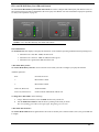
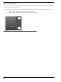
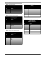
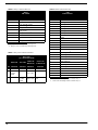
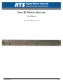
Zeus III Matrix Intercom
User Manual
Up to and including version 1.0.0
93507843000 Rev B
7/2009
Proprietary Notice
Shipping to the Manufacturer
The product information and design disclosed herein were originated by
and are the property of Bosch Security Systems, Inc. Bosch reserves all
patent, proprietary design, manufacturing, reproduction, use and sales
rights thereto, and to any article disclosed therein, except to the extent
rights are expressly granted to others.
All shipments of product should be made via UPS Ground, prepaid (you
may request from Factory Service a different shipment method). Any
shipment upgrades will be paid by the customer. The equipment should
be shipped in the original packing carton. If the original carton is not
available, use any suitable container that is rigid and of adequate size. If
a substitute container is used, the equipment should be wrapped in paper
and surrounded with at least four (4) inches of excelsior or similar
shock-absorbing material. All shipments must be sent to the following
address and must include the Proof of Purchase for warranty repair.
Upon completion of any repair the equipment will be returned via
United Parcel Service or specified shipper, collect.
Copyright Notice
Copyright 2009 by Bosch Security Systems, Inc. All rights reserved.
Reproduction, in whole or in part, without prior written permission from
Bosch is prohibited.
WARRANTY NOTICE
See the enclosed warranty card for further details.
CUSTOMER SUPPORT
Factory Service Department
Bosch Security Systems, Inc.
8601 East Cornhusker Hwy.
Lincoln, NE 68507 U.S.A.
Attn: Service
Technical questions should be directed to:
Customer Service Department
Bosch Security Systems, Inc.
12000 Portland Avenue South
Burnsville, MN 55337 USA
[email protected]
Telephone: 800-392-3497
Fax: 800-323-0498
RTS Technical Support EMEA
Telex Communications (UK) Ltd.
www.rtsintercoms.com
Telephone: 44-1707-2809-60
Return Shipping Instructions
Customer Service Department
Bosch Security Systems, Inc. (Lincoln, NE)
Telephone: 402-467-5321
Fax: 402-467-3279
Factory Service: 800-553-5992
Please include a note in the box which supplies the company name,
address, phone number, a person to contact regarding the repair, the type
and quantity of equipment, a description of the problem and the serial
number(s).
THE LIGHTNING
FLASH AND
ARROWHEAD
WITHIN THE TRIANGLE IS A WARNING
SIGN ALERTING
YOU OF “DANGEROUS VOLTAGE”
INSIDE THE PRODUCT.
CAUTION: TO REDUCE THE
RISK OF ELECTRIC SHOCK,
DO NOT REMOVE COVER. NO
USER-SERVICABLE PARTS
INSIDE. REFER SERVICING TO
QUALIFIED SERVICE PERSONNEL.
THE EXCLAMATION POINT
WITHIN THE
TRIANGLE IS A
WARNING SIGN
ALERTING YOU
OF IMPORTANT
INSTRUCTIONS
ACCOMPANYING THE PRODUCT
SEE MARKING ON BOTTOM/BACK OF PRODUCT
WARNING: APPARATUS SHALL NOT BE EXPOSED TO DRIPPING OR
SPLASHING AND NO OBJECTS FILLED WITH LIQUIDS, SUCH AS VASES,
SHALL BE PLACED ON THE APPARATUS.
WARNING: THE MAIN POWER PLUG MUST REMAIN READILY OPERABLE.
CAUTION: TO REDUCE THE RISK OF ELECTRIC SHOCK, GROUNDING OF
THE CENTER PIN OF THIS PLUG MUST BE MAINTAINED.
WARNING: TO REDUCE THE RISK OF FIRE OR ELECTRIC SHOCK, DO NOT
EXPOSE THIS APPRATUS TO RAIN OR MOISTURE.
WARNING: TO PREVENT INJURY, THIS APPARATUS MUST BE SECURELY
ATTACHED TO THE FLOOR/WALL/RACK IN ACCORDANCE WITH THE
INSTALLATION INSTRUCTIONS.
This product is AC only.
This product meets Electromagnetic Compatibility Directive 89/336/EEC.
Important Safety Instructions
1.
Read these instructions.
2.
Keep these instructions.
3.
Heed all warnings.
4.
Follow all instructions.
5.
Do not use this apparatus near water.
6.
Clean only with dry cloth.
7.
Do not block any ventilation openings. Install in accordance with the
manufacturer’s instructions.
8.
Do not install near any heat sources such as radiators, heat registers, stoves,
or other apparatus (including amplifiers) that produce heat.
9.
Do not defeat the safety purpose of the polarized or grounding-type plug. A
polarized plug has two blades with one wider than the other. A grounding
type plug has two blades and a third grounding prong. The wide blade or the
third prong are provided for your safety. If the provided plug does not fit into
your outlet, consult an electrician for replacement of the obsolete outlet.
10.
Protect the power cord from being walked on or pinched particularly at
plugs, convenience receptacles, and the point where they exit from the
apparatus.
11.
Only use attachments/accessories specified by the manufacturer.
12.
Use only with the cart, stand, tripod, bracket, or table specified by the
manufacturer, or sold with the apparatus. When a cart is used, use caution
when moving the cart/apparatus combination to avoid injury from tip-over.
13.
Unplug this apparatus during lightning storms or when unused for long
periods of time.
14.
Refer all servicing to qualified service personnel. Servicing is required when
the apparatus has been damaged in any way, such as power-supply cord or
plug is damaged, liquid has been spilled or objects have fallen into the
apparatus, the apparatus has been exposed to rain or moisture, does not
operate normally, or has been dropped.
Table
of
Contents
INTRODUCTION ........................................................................................................................................ 9
General Description ..................................................................................................................................................9
Features .....................................................................................................................................................................9
Reference View ........................................................................................................................................................10
Specifications ...........................................................................................................................................................11
Indicators and Controls ...........................................................................................................................................12
STATUS LEDS .........................................................................................................................................................................12
CH A AND CH B 2W/PARTY LINE LEDS AND CONTROLS .......................................................................................................13
POWER 1 AND POWER 2 LED .................................................................................................................................................14
Connector Pinouts ...................................................................................................................................................15
Dip Switches ............................................................................................................................................................17
S1 DIP SWITCH .......................................................................................................................................................................19
S2 DIP SWITCH .......................................................................................................................................................................20
2-Wire Settings in AZedit ........................................................................................................................................21
USE DIP SWITCH SETTINGS RADIO BUTTON ...........................................................................................................................21
MANUALLY OVERRIDE SETTINGS RADIO BUTTON ....................................................................................................................21
Zeus III and GPIO-16 ..............................................................................................................................................22
Zeus and Accessory Dimensions .............................................................................................................................24
CABLES ...................................................................................................................................................... 25
Cable Requirements .................................................................................................................................................25
INSTALLATION ........................................................................................................................................ 29
Requirements ...........................................................................................................................................................29
Default Ethernet IP Addresses ................................................................................................................................29
Initial Power Up ......................................................................................................................................................30
Zeus III Configuration .............................................................................................................................................31
SERIAL CONFIGURATION .........................................................................................................................................................31
USB CONFIGURATION ............................................................................................................................................................32
ETHERNET CONFIGURATION ...................................................................................................................................................34
INITIAL IP CONFIGURATION OF THE ZEUS III .........................................................................................................................37
Typical System Installations ....................................................................................................................................39
2-WIRE CHANNEL A AND B CONFIGURATION ..........................................................................................................................39
AUDIOCOM (BALANCED) MODE CONFIGURATION FOR SINGLE CHANNEL SYSTEM ...................................................................40
CLEARCOM (UNBALANCED) MODE CONFIGURATION ..............................................................................................................41
KEYPANEL CONFIGURATION ...................................................................................................................................................42
TRUNKING CONFIGURATION ...................................................................................................................................................42
PARTY LINE INTRODUCTION AND OPERATION ..............................................................................43
Party Line Operation .............................................................................................................................................. 43
PARTY LINE GAIN ADJUSTMENT WITH ZEUS III .......................................................................................................................44
CALL SIGNALLING ...................................................................................................................................................................45
ZEUS III AND VOX ...................................................................................................................................49
ADJUST BOX ...........................................................................................................................................................................50
SET TO BUTTON AND SLIDER ..................................................................................................................................................50
ADJUST BOX ...........................................................................................................................................................................50
SET TO BUTTON AND SLIDER ..................................................................................................................................................51
SHOW ENABLED ONLY CHECK BOX ........................................................................................................................................51
REAL-TIME CHANGES CHECK BOX .........................................................................................................................................51
PORT COLUMN .......................................................................................................................................................................51
ALPHA COLUMN .....................................................................................................................................................................51
SUPPORTED? COLUMN ...........................................................................................................................................................51
ENABLED? COLUMN ...............................................................................................................................................................51
THRESHOLD COLUMN .............................................................................................................................................................51
HOLD TIME COLUMN .............................................................................................................................................................52
AUDIO? COLUMN ...................................................................................................................................................................52
ENABLE VOX BUTTON .............................................................................................................................................................52
DISABLE VOX BUTTON ............................................................................................................................................................52
RESET THRESHOLD BUTTON ...................................................................................................................................................52
RESET HOLD TIME BUTTON ....................................................................................................................................................52
SELECT ALL BUTTON ..............................................................................................................................................................53
DE-SELECT ALL BUTTON ........................................................................................................................................................53
INVERT SELECTIONS BUTTON ..................................................................................................................................................53
CHANGING THE IP PROPERTIES ON YOUR PC ................................................................................55
UPL RESOURCE GUIDE ..........................................................................................................................59
COMMENT FIELD ....................................................................................................................................................................60
ENABLED CHECK BOX ............................................................................................................................................................60
TYPE AND VARIABLE DROP DOWN MENU ...............................................................................................................................61
INVERT INPUT A CHECK BOX ..................................................................................................................................................62
OPERATION DROP DOWN MENU .............................................................................................................................................62
TYPE AND VARIABLE DROP DOWN MENUS ..............................................................................................................................63
INVERT INPUT B CHECK BOX ..................................................................................................................................................64
TYPE AND VARIABLE DROP DOWN MENUS ..............................................................................................................................64
DESCRIPTION FIELD ...............................................................................................................................................................66
Notes ....................................................................................................................................................................... 67
List
of
Figures
FIGURE 1.
FIGURE 2.
FIGURE 3.
FIGURE 4.
FIGURE 5.
FIGURE 6.
FIGURE 7.
FIGURE 8.
FIGURE 9.
FIGURE 10.
FIGURE 11.
FIGURE 12.
FIGURE 13.
FIGURE 14.
FIGURE 15.
FIGURE 16.
FIGURE 17.
FIGURE 18.
FIGURE 19.
FIGURE 20.
FIGURE 21.
FIGURE 22.
FIGURE 23.
FIGURE 24.
FIGURE 25.
FIGURE 26.
FIGURE 27.
FIGURE 28.
FIGURE 29.
FIGURE 30.
FIGURE 31.
FIGURE 32.
FIGURE 33.
FIGURE 34.
FIGURE 35.
FIGURE 36.
FIGURE 37.
Zeus III Front and Rear Reference View ......................................................................................10
Red LED Status, Orange Status, and Green Status Indicator ......................................................12
CH A and CH B 2W/Party Line LEDs and Controls ....................................................................13
Power 1 and Power 2 Status LEDs ...............................................................................................14
Screw locations on the Zeus III unit .............................................................................................17
Dip Switch Locations ....................................................................................................................18
S1 Dip Switch ................................................................................................................................19
S2 Dip Switch ................................................................................................................................20
2-Wire Settings Page ....................................................................................................................21
Keypanel / Ports Window .............................................................................................................22
Zeus and Accessory Dimensions ...................................................................................................24
Connector Numbering ...................................................................................................................26
Cable Requirements ......................................................................................................................26
Configuration Computer Cable ....................................................................................................26
Trunking Configuration Cable ......................................................................................................26
GPIO-16 Interconnect Cable ........................................................................................................26
GPIO-16/PAP/LCP Interconnect Cable .......................................................................................27
LCP Interconnect Cable ...............................................................................................................27
RJ-45 Straight Cat-5 and RJ-45 Cat-5 Crossover Cable .............................................................27
Apply power to the Zeus III. ..........................................................................................................30
Serial Connector ...........................................................................................................................31
Serial Connection – Communications Window ............................................................................32
USB Connector .............................................................................................................................32
USB Connection – Communication Window ................................................................................33
Straight Cat-5 Ethernet Connection .............................................................................................34
Communications Window – Straight Cat-5 Ethernet Cable .........................................................35
Available Intercoms Window ........................................................................................................35
Crossover Cat-5 Connection ........................................................................................................36
Communications Window – CAT-5 Crossover Cable ...................................................................37
Ethernet Setup Window .................................................................................................................37
2-Wire Channel A and B Configuration .......................................................................................39
Audiocom (Balanced) Mode Configuration for Single Channel System ......................................40
ClearCom (Unbalanced) Mode Configuration .............................................................................41
Keypanel Configuration ................................................................................................................42
Trunking Configuration ................................................................................................................42
Zeus III 4-Wire and 2-Wire Port Allocation .................................................................................43
Input/Output Gain Window ...........................................................................................................44
FIGURE 38.
FIGURE 39.
FIGURE 40.
FIGURE 41.
FIGURE 42.
FIGURE 43.
FIGURE 44.
FIGURE 45.
FIGURE 46.
FIGURE 47.
FIGURE 48.
User Programmable Statements Window – AZedit ...................................................................... 45
Edit UPL Statement Window – AZedit ......................................................................................... 46
Naming the UPL Statement .......................................................................................................... 46
Configure the Input Action ........................................................................................................... 47
Configure the Output Action ........................................................................................................ 47
VOX Window ................................................................................................................................ 49
Open the Control Panel Window ................................................................................................. 55
Open the Local Area Connection Status Window ........................................................................ 56
Open the Local Area Connection Properties Window ................................................................. 57
Enter the IP Address of the Zeus III. ............................................................................................ 58
Edit UPL Statement Window ........................................................................................................ 60
CHAPTER 1
Introduction
General Description
Introducing a totally re-engineered Zeus Intercom System—Zeus III is the next generation of small intercom system units,
giving smaller systems more options for their intercom configurations. We now have 32 channels IN/OUT and two (2)
configurable party-line channels. This system is excellent for smaller installations, as well as OB (Outside Broadcast) vans. Its
compact size is perfect for small environments with limited space. With the addition of Ethernet, the Zeus III can be
configured from virtually anywhere on the network using AZedit Intercom software. Alternatively, the Zeus III can be directly
connected to AZedit through the use of the USB connector on the front panel. The Zeus II’s 24 DB-9 connectors have been
replaced with 32, RJ-45 connectors.
Features
Redundant Power Supplies
The unit comes with two (2) completely independent power supplies powered from
separate AC (Alternating Current) feeds. Because of the extremely low power
consumption, the use of UPS (Uninterruptible Power Supply) units is possible.
USB Port
The USB (Universal Serial Bus) port is used for the AZedit Intercom software system
configuration.
Trunk Capable
Using the dedicated DB-9 trunk connector with standard RS485 protocol, the Zeus III is
able to communicate in a trunked system.
10 Additional Audio Channels
Expanding on the Zeus II’s 24-channel unit, we have added 10 additional audio channels
to the Zeus III; eight (8) channels of audio IN and OUT, as well as two (2) channels that
can be configured for party line use. The two (2) party-line channels interface two separate
2-wire lines to 4-wire lines. From the front panel, it can be configured for RTS, Audiocom
(Balanced), or ClearCom (Unbalanced) mode.
Remote Configuration
With the addition of Ethernet to the Zeus III unit, you can now remotely configure your
Zeus III intercom system using the AZedit Intercom System software.
Dynamic Keypanel
Addressing Zeus III now automatically addresses keypanels when they are connected to
the Zeus III frame. This eliminates the need for setting keypanel addresses and
maintaining port allocations.
Relays
New relay connection supports Relay 1 and Relay 2.
Simultaneous Download
Faster downloads to multiple ports supporting the same type of keypanels.
9
Reference View
FIGURE 1.
1.
2.
3.
4.
5.
6.
7.
8.
9.
10
Zeus III Front and Rear Reference View
Status LED - 2-color status LED, for a more detailed
description see “Status LEDs” on page 12.
USB Connector
Recessed Reset Button - Resets the Zeus III to its
default configuration.
Channel A Peak LED - If within the normal range of
operation, the LED lights green, if the operating range
is above the normal range the LED lights red. For more
information, see “CH A and CH B 2W/Party Line
LEDs and Controls” on page 13.
Channel A Channel Selector - Using a flathead
screwdriver, turn the indicator to the channel mode you
want to operate.
Channel A Channel LEDs - When lit green, the channel
mode is selected.
Channel B Peak LED - If within the normal range of
operation, the LED lights green, if the operating range
is above the normal range the LED lights red. For more
information, see “CH A and CH B 2W/Party Line
LEDs and Controls” on page 13.
Channel B Channel Selector - Using a flathead
screwdriver, turn the indicator to the channel mode you
want to operate.
Channel B Channel LEDs - When lit green, the channel
mode is selected.
10. Power 1 LED - When lit green, power supply 1 is
11.
12.
13.
14.
15.
16.
17.
18.
19.
20.
21.
operating normally. When unlit, the power supply is
bad.
Power 2 LED - When lit green, power supply 2 is
operating normally. When unlit, the power supply is
bad.
AC Connector
AC Connector
GPI Connector - 25-pin Female connector. For pin
outs, see Table 8 on page 16.
GPIO-16/PAP/LCP Connector - DB-9 Female
connector. For pin outs, see Table 5 on page 15.
Relays 1 & 2 Connector - DB-9 male connector. For pin
outs, see Table 6 on page 16.
CH A Connector - 3-pin XLR Female. For pin outs, see
Table 7 on page 16.
CH B Connector - 3-pin XLR Female. For pin outs, see
Table 7 on page 16.
Port Connectors - 32, RJ-45 port connectors. For pin
outs, see Table 2 on page 15.
Trunk/To PC Connector - DB-9 Female connector. For
pin outs, see Table 3 on page 15.
Ethernet Connector - RJ-45 Connector. For pin outs,
see Table 4 on page 15.
Specifications
MATRIX
Peripheral Data Port
Description:
32 keypanel ports, 2-party line ports with call signaling
RS485 for GPIO-16/LCP-102
Trunk Port
Conversion:
48.0kHz, 24-bits
RS485 for Trunking
PC Port
Programming:
AZedit via Windows
RS232 for AZedit (supports CPL)
USB Port
Memory:
USB for AZedit
Non-volatile Flash
Ethernet Port
Communication:
USB and Ethernet interface
AUDIO PERFORMANCE
10/100Mbps for remote AZedit
Call Signals:
Balanced:
Keypanel Ports
Receive:
Signal Type:
20kHz ±100Hz, 100mVrms
Balanced
Send:
Nominal Level:
8dBu
20kHz ±100Hz, 500mVrms
RTS Channel 1 and Channel 2
Maximum Level:
Receive:
20dBu
20kHz ±100Hz, 100mVrms
Input Impedance:
Send:
22kΩ
Output Impedance:
20kHz ±200Hz, 350mVrms
ClearCom (Unbalanced) (DC-call)
600Ω
Receive:
SNR at 20dBu(A-weighted):
4VDC
>85dB
Send:
THD+N at 20dBu, 1kHz (unweighted):
<0.007%
Frequency Response at 20dBu:
12VDC
Controls
Reset Switch:
within ±1dB from 50Hz - 20kHz
Crosstalk at 20dBu:
< -80dBu
Note: All measurements performed using an Audio Precision
System 1 Dual Domain System at f=1kHz and Level=20dBu.
Measurement bandwidth= 20Hz to 20kHz.
Party Line Ports
Nominal Operating Levels:
Audiocom: 1 VRMS
RTS/TW/ClearCom: 775mVRMS
Nominal Input/Output:
5kΩ
Frequency Response:
200Hz to 3.5kHz, ±4dB
THD:
Accessible from the front panel; recessed.
Power Requirements
AC Input:
90-264VAC 50/60Hz
Power Consumption
42 Watts (Full Load)
Physical Dimension
1.72” H x 19” W x 15” D
(4.37cm H x 48.26cm W x 38.1cm D)
Weight
7.0lbs (3.18kg)
NOTE:
It is recommended to mount the Zeus III with a
half inch (1/2”) spacing on the top and bottom of
the unit to allow for proper air flow.
<1% at channel output with nominal input
DATA PORTS
Keypanel Data Ports
RS485 with dedicated transceivers for every port.
11
Indicators and Controls
Status LEDs
When the Zeus III powers on each time, the Status LED, located on the front panel (see Figure 2), cycle through a three (3)
color sequence as it verifies the Zeus III is working properly. The LED color cycle starts with Red, goes to Orange, and ends
with Green.
Red -
System Malfunction
Orange -
Boot Load Mode
NOTE:
Green -
If Switch S1-7 is set to ON (Force Boot Loader Mode, see Table 9 on page 19) and the Zeus III unit is
powered on, the LED stays at the Orange level of the color cycle, indicating you are in boot loader
mode.
Normal Operation
Red LED
FIGURE 2.
12
Orange LED
Red LED Status, Orange Status, and Green Status Indicator
Green LED
CH A and CH B 2W/Party Line LEDs and Controls
The CH A and CH B 2W/Party Line LEDs and Controls are used to configure dual-channel party line interface. Ports 33
and 34 in the intercom system are designated as the 2-wire party line channels. For more information on party line operation,
see “Party Line Operation” on page 43.
FIGURE 3.
CH A and CH B 2W/Party Line LEDs and Controls
Peak LED Indicator
The Peak LED indicator displays if the party line channel or 2-wire channel is operating within the normal operating levels.
•
•
•
When the level is less than -12dBu, the LED is off.
When the level is between -12dBu to 1dBu, the LED is green.
When the level is greater than 1dBu, the LED is red.
2-Wire Mode Rotary Switch
The 2-Wire Mode Rotary Switch is used to select the 2-wire mode you want to configure your party line channel.
Available options are:
OFF -
No modes are active
1-
RTS Channel 1 mode
2-
RTS Channel 2 mode
Audiocom (Balanced) -
Audiocom Mode
ClearCom (Unbalanced) -
ClearCom mode. Unbalanced with DC call
To change the 2-Wire Mode, do the following:
1.
Using a flathead screwdriver, insert the head into the rotary switch slot.
2.
Turn the flathead screwdriver until the arrow is pointing to the mode you desire.
The corresponding green LED (to the right) lights, designating your selection.
2-Wire Mode LED Indicators
The 2-Wire Mode LED indicators signal which 2-wire mode is currently active. When a mode is active, the green LED next
to it lights.
13
Power 1 and Power 2 LED
The Zeus III has two (2) power supplies powered by independent AC feeds. This allows for full power failover protection if
one of the power supplies stops working.
Green LEDs located on the front panel (see Figure 4) indicates whether the power supply is working properly or is broken.
•
•
FIGURE 4.
14
When the green LED is lit, the power supply is working properly.
When the green LED is not lit, the power supply is not working properly.
Power 1 and Power 2 Status LEDs
Connector Pinouts
TABLE 1. USB
Connector Pin Out
TABLE 4. Ethernet
Ethernet
RJ–45(Cat5)
Front USB
Standard Type B
Pin
1
2
3
4
Function
V_BUS
DD+
GND
TABLE 2. Keypanel
Port Connector Pin Out
Connector Pin Out
Pin
1
2
3
4
5
6
7
8
Function
TX +
TX RX +
RX -
Rear Keypanel Port
(32) RJ–45(Cat5)
Pin
1
2
3
4
5
6
7
8
Function
N/C
RS485 Data Audio Out +
Audio In +
Audio In Audio Out RS485 Data +
N/C
TABLE 3. Trunking
/ To PC Connector Pin Out
Trunking/ To PC Connection
DB–9 Female
Pin
1
2
3
4
5
6
7
8
9
TABLE 5. GPIO-16/LCP/PAP
Connector Pin Out
Peripheral Data Port
(GPIO-16, LCP-102, Etc.)
DB–9 Female
Pin
1
2
3
4
5
6
7
8
9
Function
RS485 Data GND
N/C
GND
N/C
RS485 Data +
GND
N/C
N/C
Function
RS485 Data RS232 RX
RS232 TX
N/C
GND
RS485 Data +
GND
N/C
N/C
15
TABLE 6. Relay
Connector Pin Out
TABLE 8. GPI
Relays
DB–9 Male
Pin
1
Function
2
Relay 1:NO1
+12V through 300Ω
GPI
DB-25 Female
1
Relay 1:NC
3
4
Relay 2:NC2
5
Relay 2:NO2
6
Relay 1:Common1
GND
GND
7
8
9
Relay 2:Common2
1. Relay 1 is also controlled by GPI Output #1
2. Relay 2 is also controlled by GPI Output #2
TABLE 7. Party
Line Connector Pin Out
Party Line
(2) 3-Pin Female XLR
Audiocom
RTS CH1 RTS CH2 (Balanced)
Pin Function
1 Common
2 Audio
+CALL
signal
3
16
Clear Com
(Unbalanced)
Function Function
Function
Common Common
Common
CH1 Audio
Low +Call
Audio
+CALL
signal
Connector Pin Out
CH1 Audio Audio + DC
High +Call Call
Pin
1
2
3
4
5
6
7
8
9
10
11
12
13
14
Function
GPI Input #1
GPI Input #2
GPI Input #3
GPI Input #4
GPI Input #5
GPI Input #6
GPI Input #7
GPI Input #8
GND
GND
GND
GND
GND
15
GPI Output #22
GPI Output #3
GPI Output #4
GPI Output #5
GPI Output #6
GPI Output #7
GPI Output #8
GND
GND
GND
GND
16
17
18
19
20
21
22
23
24
25
GPI Output #11
1. Control for GPI Output #1 also controls relay 1.
2. Control for GPI Output #2 also controls relay 2.
Dip Switches
To access the dip switches in the Zeus III unit, do the following:
1.
Using a Phillips head screwdriver, remove the four (4) top screws (see Figure 5).
FIGURE 5.
Screw locations on the Zeus III unit
2.
Remove the three (3) screws located on the right-side of the unit.
3.
Remove the three (3) screws located on the left-side of the unit.
4.
Carefully remove the top cover panel and set it to the side.
5.
Using Figure 6, locate the dip switch you want to configure.
6.
Using Table 9 on page 19 or Table 10 on page 20, configure the dip switch as required.
17
FIGURE 6.
18
Dip Switch Locations
S1 Dip Switch
FIGURE 7.
S1 Dip Switch
TABLE 9. Dip
Switch S1 Reference
Dip Switch
1
Description
Serial Baud Rate
Set1
Default Setting
Off
Off = 9600 baud
On= 38.4k
2
Authentication Not Required when using USB Connection
Off
Off = Authentication not required
On = Authentication required when using the USB connection
3
Reserved, Do Not Modify
Off
4
Reserved, Do Not Modify
Off
5
Reserved, Do Not Modify
Off
6
Reserved, Do Not Modify
Off
7
Force Boot Loader Mode
Off
Off = normal mode
On = force boot loader mode
8
Reserved, Do Not Modify
Off
1. Make sure the rate set here matches the rate set in AZedit. A 9600 baud permits a longer PC cable, but uploads and downloads are
slower (approximately 30 seconds for a complete system update). Alternatively, 38.4 kbaud provides faster uploads and downloads,
but the PC cable should be kept to a length less than 10 ft (3m), and some older PC's may not operate reliably at this speed.
19
S2 Dip Switch
FIGURE 8.
S2 Dip Switch
TABLE 10. S2
Dip Switch Reference
Dip Switch
1
Description
Noise Suppression on 2-Wire Port 1
Default Setting
Off
Off = disable noise suppression on 2-wire port 1
On = enable noise suppression on 2-wire port 1
2
Half-Duplex Mode on 2-Wire Port 1
Off
Off = enable half-duplex mode on 2-wire port 1
On = disable half-duplex mode on 2-wire port 1
3
Noise Suppression on 2-Wire Port 2
Off
Off = disable noise suppression on 2-wire port 2
On = enable noise suppression on 2-wire port 2
4
Half-Duplex Mode on 2-Wire Port 2
Off = enable half-duplex mode on 2-wire port 2
On = disable half-duplex mode on 2-wire port 2
20
Off
2-Wire Settings in AZedit
The 2-Wire Setting window, showin in Figure 9, is used to override the DIP switch settings you set on the Zues III unit (see
“Dip Switches” on page 17) using AZedit.
NOTE:
CH-A or CH-B must be selected for the 2-Wire Settings page to be available.
NAVIGATION: On the Keypanel / Ports Window, select the Edit button (see Figure 10).
FIGURE 9.
2-Wire Settings Page
2-Wire Settings Group Box
Use the 2-Wire Settings options to either use the currently set DIP switches, as set in the Zeus III or to override the DIP switch
settings for the selected channel. You can set CH-A and CH-B independent from each other, if desired.
Use DIP Switch Settings Radio Button
The Use DIP Switch Settings radio button indicates the currently set DIP switch settings should be used. The current settings
are displayed below the radio button.
Manually Override Settings Radio Button
The Manually Override Settings radio button allows the user to select override options to the currently set DIP switch
options. Once the Manually Override Settings radio button is selected, the override options check boxes become active below
the radio button.
Available override check box options are:
Half Duplex Check Box - Half Duplex operation is enabled.
Full Duplex Check Box - Full Duplex operation is enabled. Audio flows in both directions simultaneously.
Disable Noise Suppression Check Box - Noise suppression is disabled.
Enable Noise Suppression Check Box - Noise suppression is enabled.
21
To configure the 2-wire settings, do the following:
1.
From the System menu in AZedit, select Keypanel Assignment.
The Keypanel / Ports window appears.
FIGURE 10.
Keypanel / Ports Window
2.
From the Alphas drop down list, select CH-A or CH-B.
3.
Click Edit.
The Keypanel / Port Configuration Window appears.
4.
Click the 2-Wire Settings tab.
The 2-Wire Settings page appears.
5.
Make the configuration modifications you desire.
6.
Click Apply.
The changes are applied.
7.
Click OK.
The Keypanel / Port Configuration window closes.
8.
Send Changes to the Intercom.
Zeus III and GPIO-16
You can connect a GPIO-16 to the Zeus III intercom system. A GPIO-16 provides 16 GPI (General Purpose Inputs) and 16
GPO (General Purpose Outputs). GPIs can be set up as remotely controlled keypanel keys to activate intercom ports, party
lines, GPOs, etc. within the intercom system. GPOs are typically assigned for activation from keypanel keys. They can be used
to control lighting or to key remote transmitters, paging systems, etc.
22
The maximum number of devices that can be connected when using a GPIO-16 are as follows:
•
•
NOTE:
Zeus, Zeus II, and ADAM CS = Four (4) devices (64 relays)
ADAM, Zeus III and Cronus = 16 devices (256 relays)
In the AZedit GPI Output window, Relays 1 – 8 are dedicated to Zeus III GPI Output. In the AZedit GPI Input
window, GPI Inputs 1 – 8 are dedicated to Zeus III GPI Inputs.For more information on the GPIO-16, see the
GPIO User Manual (9350-7842-000).
23
Zeus and Accessory Dimensions
FIGURE 11.
NOTE:
24
Zeus and Accessory Dimensions
Front panel rack mounts fit industry standard 19” (483mm) racks and consoles. Dimensions exclude connectors.
Allow at least 2 inches (51mm) for cables and connections.
CHAPTER 2
Cables
Each Zeus III intercom system has unique requirements for cables, so it is not practical to apply these with the unit. A USB
interconnect cable has been provided, but even this may not be long enough for your system layout requirements. Most cables
need to be custom built. The following paragraphs and diagrams contain some useful general information for those who are
not familiar with cable construction. Connection diagrams are also included for all of the common types of Zeus III
connections.
Cable Requirements
We recommend 22AWG, stranded, twisted pair cable for your connections. For most applications, you can use unshielded
cable. Shielded cable is only required when some condition in the environment is inducing noise into the intercom system. For
keypanels and the TIF, the cables should have three (3) twisted pairs. To connect 4-wire audio devices, you need two (2)
twisted pair cables. The LCP-102 and GPIO-16 require a single twisted pair. Ask your intercom dealer about recommended
sources for cabling.
25
FIGURE 14.
Configuration Computer Cable
IMPORTANT: Pins 2 and 3 are switched between the
two (2) connectors.
FIGURE 12.
Connector Numbering
FIGURE 13.
26
Cable Requirements
FIGURE 15.
Trunking Configuration Cable
FIGURE 16.
GPIO-16 Interconnect Cable
FIGURE 17.
FIGURE 18.
GPIO-16/PAP/LCP Interconnect Cable
LCP Interconnect Cable
RJ-45 Straight Cat-5 and RJ-45 Cat-5
Crossover Cable
FIGURE 19.
27
28
CHAPTER 3
Installation
Requirements
•
AZedit version 3.6.2 or later
Default Ethernet IP Addresses
TABLE 11. Default
Product
RVON-I/O
RVON-8
RVON-1
RVON-C
RVON-16
GPIO-16
MCII-e
Cronus
Zeus III
Ethernet IP Addresses
Default IP Address
192.168.0.1
192.168.0.2
192.168.0.3
192.168.0.4
192.168.0.5
192.168.0.6
192.168.0.7
192.168.0.8
192.168.0.9
Default Subnet Mask
255.255.0.0
255.255.0.0
255.255.0.0
255.255.0.0
255.255.0.0
255.255.0.0
255.255.0.0
255.255.0.0
255.255.0.0
29
Initial Power Up
To power on the Zeus III unit, do the following:
1.
Attach the power cord to the power entry module on the rear of the Zeus III.
FIGURE 20.
2.
Apply power to the Zeus III.
Plug the other end of the power cord into the electrical outlet.
The unit powers on. The Status LED, located on the front panel (see Figure 2 on page 12), cycles through a three (3)
color sequence as it verifies the Zeus III is working properly. The LED color cycle starts with Red, goes to Orange,
and ends with Green.
NOTE: Repeat step 1 and step 2 for redundant power supplies.
30
Zeus III Configuration
There are three (3) configuration types for Zeus III operation:
•
•
•
NOTE:
RS-232 (serial)
USB
Ethernet
You can only use one (1) type of communication configuration at a time. For example, if the Zeus III is
connecting to AZedit via USB, it cannot also connect over Ethernet at the same time.
Serial Configuration
To configure the Zeus III for serial configuration, do the following:
1.
Attach a serial cable to the Trunk/To PC connector on the rear of the Zeus III.
FIGURE 21.
2.
Serial Connector
Attach the other end of the serial cable to any available serial connector on the computer with AZedit loaded on it.
31
3.
In AZedit, from the Options menu, select Communications.
The Communications window appears.
FIGURE 22.
Serial Connection – Communications Window
4.
Select the Serial radio button.
5.
Click OK.
The Zeus III is configured to connect to AZedit serially.
USB Configuration
NOTE:
If you are configuring a USB connection for the first time, you must manually navigate to the USB drivers at
C:\Telex\AZedit\USB.
To configure the Zeus III for USB configuration, do the following:
1.
Attach the supplied USB cable to the USB connector located on the front of the Zeus III.
FIGURE 23.
32
USB Connector
2.
Attach the other end of the USB cable to any available USB connector on the computer with AZedit loaded on it.
3.
In AZedit, select Options|Communications.
The Communications window appears.
FIGURE 24.
USB Connection – Communication Window
4.
Select the USB radio button.
5.
Click OK.
The Zeus is configured to connect to AZedit via USB.
33
Ethernet Configuration
There are two (2) ways to connect the Zeus III to AZedit over Ethernet:
•
•
NOTE:
Using a straight CAT-5 Ethernet cable and connecting to an existing IP Network.
Using a fabricated CAT-5 crossover cable and connecting directly to the AZedit computer. (For the CAT-5
crossover cable pin out, see Figure 19 on page 27.)
The straight CAT-5 cable assembly cannot be directly connected to the computer with AZedit loaded on it. It can
only be used with a router or switch that is connected to the computer. Use the CAT-5 crossover cable to directly
connect to the Zeus III with Ethernet.
To configure the Zeus III for Ethernet configuration using the supplied Ethernet cable, do the following:
1.
Attach the Ethernet cable to your existing IP network using a network router or switch.
FIGURE 25.
2.
Attach the other end of the Ethernet cable to the Ethernet connector located on the rear of the Zeus III.
NOTE:
34
Straight Cat-5 Ethernet Connection
By default, Zeus III is shipped with the IP Address 192.68.0.9 and the Network Mask 255.255.0.0.
To change the IP Address, initially you must connect either serially or via USB.
3.
From Options menu, select Communications.
The Communications window appears.
FIGURE 26.
Communications Window – Straight Cat-5 Ethernet Cable
4.
Select the Network radio button.
5.
Click the browse button.
The Available Intercoms window appears.
FIGURE 27.
Available Intercoms Window
6.
From the Intercoms list field, select the Zeus III intercom you want to connect to.
7.
Click OK.
The Available Intercoms window closes and the Communications window appears.
8.
Click OK.
The Communications window closes. The Zeus III is configured for Ethernet operation via the supplied cable.
35
To configure the Zeus III for Ethernet configuration using the CAT-5 crossover cable, do the following:
By default, Zeus III is shipped with the IP Address 192.168.0.9 and the Network Mask 255.255.255.0. To change the IP
Address, you must initially connect either serially or via USB. For crossover cable construction, see Figure 19 on page 27.
NOTE:
1.
If access to serial port and USB is not available on the host PC, you must configure your TCP/IP properties on
the PC to match the Zeus III unit subnet (192.168.0.X) for proper communication.
Using the CAT-5 crossover cable, attach one end to the Ethernet connector located on the rear of the Zeus III.
FIGURE 28.
2.
36
Crossover Cat-5 Connection
Attach the other end of the crossover cable to an Ethernet port on the computer with AZedit loaded.
3.
In AZedit, from the Options menu, select Communications.
The Communications window appears.
FIGURE 29.
Communications Window – CAT-5 Crossover Cable
4.
Select the Network radio button.
The IP Address group box becomes active.
5.
Click OK.
The Communications window closes. The Zeus III is configured for Ethernet operation via the CAT-5 crossover cable.
Initial IP Configuration of the Zeus III
By default, the Zeus III is shipped with the IP Address 192.168.0.9 and the Net Mask 255.255.255.0. to change the IP Address
initially, you must connect either serially or via USB.
1.
Connect to the PC with AZedit via a serial or USB cable.
2.
In AZedit, from the Options menu, select Ethernet Setup.
The Ethernet Setup window appears.
FIGURE 30.
Ethernet Setup Window
3.
In the IP Address field, enter the IP Address for the Zeus III.
4.
In the Netmask field, enter the Netmask Address for the Zeus III, if needed.
5.
In the Gateway field, enter the Gateway Address for the Zeus III, if needed.
6.
Click Apply.
The IP Address, Network Mask, and Gateway Address are changed.
37
7.
Click Close.
The Ethernet Settings window closes.
NOTE: Remember to send your changes to the Matrix. To send changes to the matrix, from the edit menu, select
Send Changes
38
Typical System Installations
2-Wire Channel A and B Configuration
FIGURE 31.
NOTE:
2-Wire Channel A and B Configuration
CH A and CH B are not powered by the Zeus III, therefore a power supply must be used for party line channels.
To configure a typical 2-wire channel A and B system, do the following:
NOTE: A TW5W or TW7W breakout panel can be used to connect the 2-wire device, power supply and Zeus III
unit.
1.
Connect the Zeus III 2-wire party line channel(s) (CHA and/or CHB) to the breakout panel using a female 3-pin
XLR connector.
2.
Connect the 2-wire device to the breakout panel using the specified 3-pin XLR connector.
3.
Connect the power supply to the breakout panel using the specified 3-pin XLR connector.
4.
Depending on the channel being used by the 2-wire device, set the Zeus III 2-wire mode appropriately.
39
Audiocom (Balanced) Mode Configuration for Single Channel System
FIGURE 32.
NOTE:
Audiocom (Balanced) Mode Configuration for Single Channel System
CH A and CH B are not powered by the Zeus III, therefore a power supply must be used for party line channels.
To configure a typical balanced mode system, do the following:
NOTE: A TW5W or TW7W breakout panel can be used to connect the 2-wire device, power supply and Zeus III
unit.
40
1.
Connect the Zeus III 2-wire party line channel(s) (CHA and/or CHB) to the breakout panel using a female 3-pin
XLR connector.
2.
Connect the 2-wire device to the breakout panel using the specified 3-pin XLR connector.
3.
Connect the power supply to the breakout panel using the specified 3-pin XLR connector.
4.
Using a small, flathead screw driver, set the 2W/Party Line mode to balanced.
ClearCom (Unbalanced) Mode Configuration
FIGURE 33.
NOTE:
ClearCom (Unbalanced) Mode Configuration
CH A and CH B are not powered by the Zeus III, therefore a power supply must be used for party line channels.
To configure a typical ClearCom (unbalanced) mode system, do the following:
NOTE: A TW5W or TW7W breakout panel can be used to connect the 2-wire device, power supply and Zeus III
unit.
1.
Connect the Zeus III 2-wire party line channel(s) (CHA and/or CHB) to the breakout panel using a female 3-pin
XLR connector.
2.
Connect the 2-wire device to the breakout panel using the specified 3-pin XLR connector.
3.
Connect the power supply to the breakout panel using the specified 3-pin XLR connector.
4.
Using a small, flathead screw driver, set the 2W/Party Line mode to Clear Com (unbalanced).
41
Keypanel Configuration
FIGURE 34.
Keypanel Configuration
To configure a typical keypanel system, do the following:
>
Using an RJ-45 keypanel cable, connect the cable to a keypanel port (ports 1 to 32) located on the back of the Zeus
III unit.
NOTE: For the pin out of the RJ-45 keypanel cable, see Table 2 on page 15.
Trunking Configuration
FIGURE 35.
Trunking Configuration
To configure a trunking system, do the following:
42
1.
Connect a serial cable to the TRUNK/TO PC connector located on the rear panel of the Zeus III unit.
2.
Connect the other end of the serial cable to the serial cable connector located on the back of the MTM-2000.
3.
Use TrunkSupervisor/Editor to configure the Zeus III trunking system (for trunking configuration information,
see the TM-2000/MTM-2000 User Manual – 93507715000).
CHAPTER 4
Party Line Introduction and Operation
Party Line Operation
The Zeus III integrates 32 4-wire intercom ports (ports 1 – 32) with two (2) 2-wire intercom ports (ports 33 and 34), allowing
audio to pass between the 2-wire channels and 4-wire channels. Any 2-wire system can be connected directly to the Zeus III
without an SSA-324 or a DSI-2008, saving the space and expense of supporting two (2) units to convert the signal.
IMPORTANT:
FIGURE 36.
Channels must be configured the same between products. For example, a PS-4001 connected to CH1 of
the Zeus III must be set to BAL on both units.
Zeus III 4-Wire and 2-Wire Port Allocation
43
Party Line Gain Adjustment with Zeus III
Unlike the Zeus III 4-wire channels that can have their input and output gain adjusted, the 2-wire channels (Channel A and
Channel B) can only have their input gains adjusted. This is because there is a limit on the amount of gain a 2-wire device can
receive (see “Specifications” on page 11), therefore a limiter between the 2-wire device and the Zeus III system limits the
amount of gain received by the 2-wire device.
The range for this field is -20dB to +20dB.
The default is 0.0dB.
FIGURE 37.
Input/Output Gain Window
To adjust the party line input gain, do the following:
1.
From the System menu in AZedit, select Gains.
A flyout menu appears.
2.
From the flyout menu, select Input/Output Gains.
The Input/Output Gains window appears.
3.
Select the party line channel you want to adjust the input value (Port 33 CHA or Port 34 CHB).
NOTE: Notice in Figure 37, the Output Gain column for CHA and CHB has n/a (not available) in the output gain
column.
44
4.
From the Gain drop down menu, select the input gain amount you want to assign to the channel.
OR
Using the spinner arrows, adjust the input gain amount up or down.
5.
Click Set Input Gain when you are finished.
The input is adjusted.
Call Signalling
Zeus III party line channels (CH1 and CH2, see Figure 3 on page 13) support an integrated call signalling function controlled
through the use of UPL statements in AZedit. Using a UPL statement, you can configure an indicator to activate when calls are
received.
NOTE:
Call signalling support is only available with AZedit version 3.6.4 and later.
To configure incoming call signalling from a 2-wire system, do the following:
1.
In AZedit, from the System menu, select UPL Statements.
The User Programmable Logic Statements window appears.
FIGURE 38.
User Programmable Statements Window – AZedit
45
2.
Double-click a UPL Statement.
The Edit UPL Statement window appears.
FIGURE 39.
3.
In the comment field, enter an identifiable description for the UPL statement.
4.
Select the Enabled check box to enable the UPL statement.
FIGURE 40.
46
Edit UPL Statement Window – AZedit
Naming the UPL Statement
5.
From the Input A Type drop down menu, select Call Signal.
A port field and drop down menu appear.
6.
In the port field, enter the 2-wire channel port.
7.
From the drop down menu, select the channel the 2-wire system is connected to.
FIGURE 41.
Configure the Input Action
8.
In the Output Action Type drop down menu, select the output action you want to configure.
9.
In the Port field, enter the port number to send the call signal.
10.
From the Port drop down menu, select the channel you want to send the call signal.
11.
Using the Duration spin box, select the amount of time, in seconds, the call indicator activates (0.1 to 20 seconds).
FIGURE 42.
Configure the Output Action
47
NOTE: In the Description box, to the right of the Output Action group box, you can read a description of the UPL
Statement you just created.
12.
When finished, click Done.
The Edit UPL Statement window closes. The UPL Statement appears in the User Programmable Logic Statement
window list.
NOTE: Be sure to send your changes to the intercom system.
To send changes either:
•
•
NOTE:
48
Click the Send icon
From the Online menu, select Send Changes.
In most cases, when the input conditions for the UPL statement are true, the output action occurs. Then when the
input condition ceases to be true, the output action terminates. The exceptions are Load File, Force Keys (talk
and listen), and Force Headset Transfer. When a UPL statement loads a file, there is no way to “unload” the file
when the UPL statement is no longer true. When a talk or listen key is forced ON, or a headset is force ON, with
a UPL statement, you must use a second UPL statement to force the keys or headset OFF.
CHAPTER 5
Zeus III and VOX
The VOX window, shown in Figure 43, is used to configure Vox on ports in your intercom system. VOX is an audio threshold
level you set at the point a channel becomes active. When the threshold is set, a channel does not activate until the preset audio
level is attained. This prevents a channel from staying on when no one is around in a high activity area.
NAVIGATION: From the menu bar, select System|Vox.
NOTE:
Remember to send any changes you make to the intercom system using Edit|Send Changes or the Activate
button.
FIGURE 43.
VOX Window
49
Threshold Group Box
Adjust Box
The Adjust box is used to fine tune the VOX threshold level, in dB, for the port after using the Set To slider. Use the
adjustment arrows to increase or decrease the VOX threshold level in .5dB increments.
The range for this field is –126dB to 0.0dB.
NOTE:
The threshold change is only seen in the Threshold column to the right.
Set To Button and Slider
The Set To button and Slider is used to quickly get to the approximate threshold level, in dB, you want to set for the port.
Once you have used the slider, click the Set To button to set the level for the port. Use the Adjust arrows to fine tune the
threshold level.
To use the threshold slider, do the following:
1.
Click and hold the slider.
2.
Drag the slider left to decrease the threshold amount or right to increase the threshold amounts.
Hold Time Group Box
Adjust Box
The Adjust box is used to fine tune the hold time, in seconds, for the port after using the Set To slider. Use the adjustment
arrows to increase or decrease the VOX threshold level in .1 second increments.
The range for this field is .02 seconds to 12.5 seconds.
NOTE:
50
The time change is only seen in the Hold Time column to the right.
Set To Button and Slider
The Set To button and Slider is used to quickly get to the approximate hold time you want to set for the port. Once you have
used the slider, click the Set To button to set the time for the port. Use the Adjust arrows to fine tune the hold time.
To use the hold time slider, do the following:
1.
Click and hold the slider.
2.
Drag the slider left to decrease the hold time amount or right to increase the hold time amount.
Options Group Box
Show Enabled Only Check Box
The Show Enabled Only check box is used to show vox enabled ports only. This feature is used to quickly view ports with
vox enabled. If this check box is not selected, all available ports are shown.
Real-Time Changes Check Box
The Real-Time Changes check box is used to make changes to the vox threshold in real time. When selected and in ONLINE
mode, vox changes are automatically sent to the intercom system as you make the adjustments.
Port Column
The Port column displays all available ports in the intercom.
Alpha Column
The Alpha column displays the alphas for all the available ports in the intercom.
Supported? Column
The Supported? column displays whether vox is supported on the intercom port. If vox is supported on the port, a green Yes
appears in the column. If vox is not supported on the port, a red No appears in the column.
Enabled? Column
The Enabled? column displays whether vox is enabled on the specified port. If vox is enabled on the port, a green Yes appears
in the column. If vox is not supported on the port, a red No appears in the column.
To enable vox on the port, do the following:
>
NOTE:
Highlight the port or ports you want to enable, and then click Enable Vox.
You can also enable vox from the Keypanel/Port Configuration Window.
Threshold Column
The Threshold column displays the audio level, in dB, at which vox activates on the port.
51
Hold Time Column
The Hold Time column displays the time, in seconds, the port waits for the presence of audio before turning off.
Audio? Column
The Audio? column indicates if audio is present on the port. If audio is present, a green Yes displays in the column. If there is
not audio on the port, a red No appears in the column.
Enable Vox Button
The Enable Vox button is used to enable vox on the selected port or ports. You can also use the Vox page in the
Keypanel/Port Configuration window to enable or disable vox on a port.
NOTE:
To select more than one port to enable, do one of the following:
•
•
To select random ports, press and hold the Ctrl key and click the ports you want to select.
To select a block of ports, click the top-most port in the block; press and hold the Ctrl + Shift; press the
bottom-most port in the block.
All the ports in between the top and bottom port are selected.
Disable Vox Button
The Disable Vox button is used to disable vox on the selected port or ports. You can also use the Vox page in the
Keypanel/Port Configuration window to enable or disable vox on a port.
NOTE:
To select more than one port to disable, do one of the following:
•
•
To select random ports, press and hold the Ctrl key and click the ports you want to select.
To select a block of ports, click the top-most port in the block; press and hold the Ctrl + Shift; press the
bottom-most port in the block.
All the ports in between the top and bottom port are selected.
Reset Threshold Button
The Reset Threshold button is used to return the threshold levels of the selected port or ports to the default level.
The default threshold level is -30.0dB.
NOTE:
To select more than one port to reset, do one of the following:
•
•
To select random ports, press and hold the Ctrl key and click the ports you want to select.
To select a block of ports, click the top-most port in the block; press and hold the Ctrl + Shift; press the
bottom-most port in the block.
All the ports in between the top and bottom port are selected.
Reset Hold Time Button
The Reset Hold Time button is used to return the hold time for the selected port or ports to the default time.
The default hold time is 0.5 seconds.
NOTE:
To select more than one port to reset, do one of the following:
•
•
52
To select random ports, press and hold the Ctrl key and click the ports you want to select.
To select a block of ports, click the top-most port in the block; press and hold the Ctrl + Shift; press the
bottom-most port in the block.
All the ports in between the top and bottom port are selected.
Select All Button
The Select All button highlights all of the items from the Available or Selected list.
De-Select All Button
The De-select All button de-selects any selected items from the Available or Selected list.
Invert Selections Button
The Invert Selections button reverses the selections in the current view. For example, if ports 1 through 5 are highlighted,
while ports 6 through 10 are not, when the Invert Selection button is clicked, ports 1 through 5 are deselected and ports 6
through 10 become highlighted.
53
54
APPENDIX A
Changing the IP Properties on your PC
IMPORTANT:
NOTE:
Before you change any network settings on your computer, please make note of the current settings.
The following instructions are for Microsoft XP operating system and may differ slightly for other operating
systems.
To change the IP properties on your PC, do the following:
1.
Disable any Ethernet connections on the PC you want to alter the IP Properties for.
2.
From the Windows Start menu, select Settings.
A flyout menu appears.
FIGURE 44.
Open the Control Panel Window
55
3.
From the flyout menu, select Control Panel.
The Control Panel window appears.
4.
Double-click Network Connections.
The Network Connections window appears.
5.
Right-click the Local Area Connection.
6.
Select Properties.
The Local Area Connection Status window appears.
FIGURE 45.
56
Open the Local Area Connection Status Window
7.
Click Properties.
The Local Area Connection Properties window appears.
FIGURE 46.
Open the Local Area Connection Properties Window
8.
Select Internet Protocol (TCP/IP) from the connection list.
9.
Click Properties.
The Internet Protocol (TCP/IP) Properties window appears.
TIP:
Remember to note the current settings.
57
10.
Select the Use the following IP address radio button.
The corresponding IP Address fields become active.
FIGURE 47.
58
Enter the IP Address of the Zeus III.
11.
In the IP address field, enter the IP Address you want to configure for the Zeus III, if desired.
12.
In the Subnet mask field, enter the Subnet Mask you want to configure the Zeus III, if desired.
13.
In the Default gateway field, enter the Gateway Address you want to configure for the Zeus III, if desired.
14.
Click OK.
The IP (TCP/IP) Properties window closes.
15.
Click OK.
The Local Area Connection Properties window closes and the IP Address has been changed.
APPENDIX B
UPL Resource Guide
UPL (User Programmable Language) is a powerful feature which lets you quickly and easily program the intercom system to
perform output actions you specify based on input conditions you specify. The UPL Statements window displays information
concerning the UPL statements configured for your intercom system.
EXAMPLE:
You can program the intercom system to load a new setup file at a specified time or load whenever
someone presses a particular keypanel key. On the other hand, you can program talk and listen path
to turn on or off at specified times. Using UPL Statements Setup, you can build the custom
operations quickly and easily to get the most out of your intercom system.
Use the Edit UPL Statement window to create your customized UPL statements.
To access the Edit UPL Statements window, do the following:
1.
From the Alphas menu, select UPL Statements.
The User programmable Logic Statements window appears.
2.
Double-click the UPL Statement you want to create.
The Edit UPL Statement window appears.
59
FIGURE 48.
Edit UPL Statement Window
UPL Statement Group Box
Comment Field
The Comment field is used to enter a description or comment about the current UPL statement.
This field can contain up to 32 characters.
Enabled Check Box
The Enabled check box indicates the UPL statement is enabled and ready to use. Clear the check box to disable the UPL
statement, but not delete it.
60
Input A Group Box
Type and Variable Drop Down Menu
The Type and Variable drop down menu is used to select an input condition that causes the intercom system to perform an
output action. Each UPL statement can have either one (1) or two (2) input conditions. Depending on which is selected from
the Type drop down menu, dictates what variable is needed.
Use Table 12 on page 61 to determine the type and variables you want to use.
TABLE 12. Input
A and Variables
Input Condition
Input Description
UPL Statement
GPI Input
GPI Input (Local)
If a specified UPL statement is true...
If a system GPI Input is activated....
If a Local GPI Input is activated...
GPI Output
GPI Output (Local)
If a system GPI Output is activated...
If a Local GPI Output is activated...
Talk Key
If a specified Talk Key on a keypanel is ON...
Listen Key
If a specified Listen Key on a keypanel is ON...
UPL Resource
Crosspoint
If a UPL Resource key is activated...
If a specified Crosspoint is activated...
Input Talking
Output Listening
Headset Transfer
If a specified port is talking to anyone...
If a specified port is listening to anyone...
If the Headset Transfer switch on a keypanel is
activated...
If the Current Date is...
Current Date
Variables Needed
UPL Statement # and Description
GPI Input # and Alpha
Port # and Alpha
GPI Input # and Alpha
GPI Output # and Alpha
Port # and Alpha
GPI Output # and Alpha
Port # and Alpha
Key #
Port # and Alpha
Key #
UPL Resource # and Description
Input # and Alpha
Output # and Alpha
Input # and Alpha
Output # and Alpha
Port # and Alpha
Year, Month, and Day (YY/MM/DD).
NOTE: You must use the Operator drop down menu
Current Time
If the Current Time is...
when using the Date and/or Time input.
Hour, Minute, Second (00:00:00)
All times are entered in the 24-hour or military time
format. For example, 1:00 pm is 13:00:00.
NOTE: You must use the Operator drop down menu
IFB Interrupted
Counter
Vox Audio
Any Talk Key
Call Signal
If the specified IFB is interrupted...
If the Counter is...
when using the Date and/or Time input.
IFB # and Alpha
Counter #
NOTE:
NOTE: You must use the Operator drop down menu
Counters count increments of time.
Each counter is equal to 100ms of
time. AZedit allows for up to 256
counters to be used.
The counter input selection is used to write UPL
statements to occur in a timed event. For example,
when a key is pushed, wait 10 seconds before running
the UPL statement to turn a light ON.
If the Vox Audio is...
If Any Talk Key is on a keypanel is ON....
If a call signal is detected....
when using the Counter input.
Input # and Alpha
Port # and Alpha
Port # and Alpha
61
Invert Input A Check Box
The Invert Input A check box is used to reverse the input condition.
For example, if the input condition is Talk Key, which by itself means, when a specified talk key is on, run the assigned output.
However, by selecting the Invert Input A check box, it means a specified talk key is off, run the assigned output.
The invert check box is often used in one UPL statement to cancel an action caused by some other UPL statement.
Operation Group Box
Operation Drop Down Menu
The Operation drop down menu is used to select the type of operator to use when joining Input A and Input B or when using
the Current Date, Current Time, or the Counter input for Input A. In all other cases, the Operation drop down menu is not used.
NOTE:
Operators, also known as logical operators, are used to construct more complex searches in a database. They
help make a search more accurate. There are three (3) logical operators: AND, OR and NOT.Operators for Two
Input Conditions
Operator
AND
OR
XOR
Description
If input A and input B are both true....then run the specified output.
If input A or input B (or both) are true....then run the specified output.
If input A or input B (but not both) are true....then run the specified output.
Operators for Current Date and Current Time
Operator
=
If the current date or time equals...
!=
When the current date or time does not equal...
<
When the current date or time is earlier than...
>=
>
<=
Example:
62
Description
When the current date or time is equal to or later than...
When the current date or time is later than...
When the current date or time is equal to or earlier than...
Operators for current time have a 5-second window. For example, if you create a test for a specific time
(i.e., = 12:00:00), the given time is matched for a 5-second window. It returns a true result for the time
12:00:00 through 12:00:05. A test for inequality returns true for all but this 5-second window.
Input B Group Box
Type and Variable Drop Down Menus
The Type and Variable drop down menu is used to select an input condition that causes the intercom system to perform an
output action. Each UPL statement can have either one (1) or two (2) input conditions. Depending on which is selected from
the Type drop down menu.
Use Table 13 on page 63 to determine the type and variables you want to use.
TABLE 13. Input
B Types and Variables
Input
Condition
Input Description
Variables Needed
UPL Statement
If a specified UPL statement is true...
UPL Statement # and Description
GPI Input
If a system GPI Input is activated....
GPI Input # and Alpha
GPI Input (Local)
If a Local GPI Input is activated...
Port # and Alpha
GPI Input # and Alpha
GPI Output
If a system GPI Output is activated...
GPI Output # and Alpha
GPI Output
(Local)
If a Local GPI Output is activated...
Port # and Alpha
GPI Output # and Alpha
Talk Key
If a specified Talk Key on a keypanel is ON...
Port # and Alpha
Key #
Listen Key
If a specified Listen Key on a keypanel is ON...
Port # and Alpha
Key #
UPL Resource
If a UPL Resource key is activated...
UPL Resource # and Description
Crosspoint
If a specified Crosspoint is activated...
Input # and Alpha
Output # and Alpha
Input Talking
If a specified port is talking to anyone...
Input # and Alpha
Output Listening
If a specified port is listening to anyone...
Output # and Alpha
Headset Transfer
If the Headset Transfer switch on a keypanel is
activated...
Port # and Alpha
Target Date
If the Target Date is...
Year, Month, and Day (YY/MM/DD).
NOTE:
Target Time
Target Time is used in conjunction with Current Time.
Target Date is used in conjunction
with Current Date.
Hour, Minute, Second (00:00:00)
NOTE:
All times are entered in the 24-hour
or military time format. For
example, 1:00 pm is 13:00:00.
NOTE:
Target Time is used in conjunction
with Current Time.
IFB Interrupted
If the specified IFB is interrupted...
IFB # and Alpha
Target Value
Target Value is used in conjunction with the Counter
input.
The target value is an increment of time, in ms, to
trigger an event. 1 counter equals 100ms.
The counter input selection is used to write UPL
statements to occur in a timed event. For example,
when a key is pushed, wait 10 seconds before running
the UPL statement to turn a light ON.
NOTE:
Vox Audio
Automatically switches input A to
Counter.
If Vox Audio is...
Input # and Alpha
Any Talk Key
If Any Talk Key is on a keypanel is ON....
Port # and Alpha
Call Signal
If a Call Signal is detected
Port # and Alpha
63
Invert Input B Check Box
The Invert Input B check box is used to reverse the input condition.
For example, if the input condition is “Talk Key”, which by itself means, when a specified talk key is on, run the assigned
output. However, by selecting the Invert Input A check box, it means changes to when a specified talk key is off, run the
assigned output.
The invert check box is often used in one UPL statement to cancel an action caused by some other UPL statement.
Output Action Group Box
Type and Variable Drop Down Menus
The Type and Variable drop down menu is used to select an output result that occurs when an input definition is met.
Depending on which is selected from the Type drop down menu, dictates what variable is needed.
Use Table 14 on page 64 to determine the type and variables you want to use.
TABLE 14. Output
Values
Output
Output Description
Close Crosspoint
Close the crosspoint from the specified
input to the specified output
Input Number, Alpha, Output Number, Alpha
Inhibit Crosspoint
Open the crosspoint from the specified
input to the specified output.
Input Number, Alpha, Output Number, Alpha
Assert GPI Output
Activate the specified System GPI
Output
GPI Output Number and Alpha
Inhibit GPI Output
Deactivate the specified System GPI
Output
GPI Output Number and Alpha
Assert GPI Output (Local)
Activate the specified Local GPI Output
Port Number and Alpha, GPI Output Number
and Alpha
Inhibit GPI Output (Local)
Deactivate the specified Local GPI
Output
Port Number and Alpha, GPI Output Number
and Alpha
Force Talk Key Closure
Force the specified talk key ON
Port Number, Alpha and Key Number
Force Talk Key Open
Force the specified talk key OFF
Port Number, Alpha and Key Number
Dim Crosspoint Volume
Cause the specified output to hear the
specified input at a reduced volume
level.
Input Number, Alpha, Output Number, Alpha
and DIM amount (-1.0dB to -72.2dB, and
Mute)
Load File
Cause a file to be loaded from disk and
sent to the intercom system.
The Load File pulls files from the directory you
have configured on the General page in the
Preferences window.
NOTE:
64
Variables Needed
AZedit must be in SERVER
mode.
Force Listen Key Closure
Force the specified listen key ON
Port Number, Alpha, and Key Number
Force Listen Key Open
Force the specified listen key OFF
Port Number, Alphas, and Key Number
Clear Counter
Clear the Counter
Clears the counter input from the UPL
statement. If you select 0 all counters are
cleared
Inhibit Output
Open the output port.
Output Port Number, and Alpha
TABLE 14. Output
Values
Output
Output Description
Variables Needed
Inform Command Line
Protocol
THIS IS NOT CONFIGURABLE FROM AZEDIT. This option is used by command line
protocol only. When a query is sent from the command line protocol to AZedit, a UPL
statement is written with “Inform Command Line Protocol” as the output. This can be used
to monitor the query sent from the command line protocol.
For more information, contact customer service.
Set Headset Transfer State
Set the Headset to the specified state.
Port Number, Alpha, Headset State
Headset state selections are:
Turn Headset transfer OFF
Turn Headset transfer ON
Force Headset transfer OFF
Force Headset transfer ON
Release Headset transfer
NOTE: The difference between Turn and
Force is when force is used the user
cannot change the headset transfer
once the transfer is complete.
Set Talk Key LED State
Set the Talk Key LED State
Port Number, Alpha, Key, and LED State
LED state selections are:
Local Control
Solid Red
Solid Green
Solid Amber
Slow Red Flash
Slow Green Flash
Fast Red Flash
Fast Green Flash
Slow Red Wink
Slow Green Wink
Set Listen Key LED State
Set the Listen Key LED State
Port Number, Alpha, Key, and LED State
LED state selections are:
Local Control
Solid Red
Solid Green
Solid Amber
Slow Red Flash
Slow Green Flash
Fast Red Flash
Fast Green Flash
Slow Red Wink
Slow Green Wink
65
TABLE 14. Output
Values
Output
Set IFB Program Input
Output Description
Set the Program Input Port for an IFB
assignment.
Variables Needed
IFB Number, Alpha, Input Port Number, and
Alpha
NOTE: If you set the Input Port Number to 0,
you are assigning no input port.
Start Paging System Macro
Send a signal over a serial connection to
a paging system to start a macro.
NOTE:
Stop Paging System Macro
The macro is stored in the
paging system. AZedit sends
an event to trigger the macro
on the Paging System.
Send a signal over a serial connection to
a paging system to end the macro.
NOTE:
Macro Number
Macro Number
The macro is stored in the
paging system. AZedit sends
an event to trigger the macro
on the Paging System
Generate Call Signal
Sends a call signal to the specified port
Port #, Alpha, and Signal Duration
Generate Mic Kill
Sends a mic kill signal
Port #, Alpha, and Signal Duration
NOTE:
In most cases, when the input conditions for the UPL statement are true, the output action occurs. Then, when the
input condition ceases to be true, the output action terminates. The exceptions are Load File, Force Keys (talk
and listen), and Force Headset Transfer. When a UPL statement loads a file, there is no way to unload the file
when the UPL statement is no longer true. When a talk or listen key is forced on, or a headset is force on, with a
UPL statement, you must use a second UPL statement to force the keys or headset off.
Description Field
The Description field displays a plain-text description of the UPL statement you build. You can use this description to verify
the UPL statement is constructed to run as anticipated.
66
Notes
67