1
PARTNER®
Advanced Communications System
Installation, Programming, and Use
518-456-803
Comcode 108848292
Issue 1
October 2000
Copyright 2000
Avaya Inc.
All Rights Reserved
Printed in USA
Document Number: 518-456-803
Comcode: 108848292
Issue: 1
Date: October 2000
Notice
Every effort was made to ensure that the information in this book was complete
and accurate at the time of printing. However, information is subject to change.
Ordering Information
Call:
Publications Center
Voice 1 800 457-1235 International Voice +1 317 322-6791
Fax 1 800 457-1764 International Fax +1 317 322-6699
Write:
Publications Center
2855 N. Franklin Road
Indianapolis, IN 46219 USA
Federal Communications Commission Statement
This equipment has been tested and found to comply with the limits for a Class A
digital device, pursuant to Part 15 of the FCC Rules. These limits are designed to
provide reasonable protection against harmful interference when the equipment
is operated in a commercial environment. This equipment generates, uses, and
can radiate radio-frequency energy and, if not installed and used in accordance
with the instructions, may cause harmful interference to radio communications.
Operation of this equipment in a residential area is likely to cause harmful interference, in which case the user will be required to correct the interference at his
own expense. This system is Class B compliant in some configurations. See the
PARTNER Customer Support Document for additional FCC information.
For additional documents, refer to the PARTNER Customer Support Document.
Customer Support
Industry Canada (IC) Interference Information
If you need assistance when programming or using your system, contact your
local Authorized Dealer or call the helpline at 1 800 628-2888. Consultation
charges may apply.
This digital apparatus does not exceed the Class A limits for radio noise emissions set out in the radio interference regulations of Industry Canada.
Obtaining Products
Le Présent Appareil Nomérique n’émet pas de bruits radioélectriques dépassant
les limites applicables aux appareils numériques de la class A préscrites dans le
reglement sur le brouillage radioélectrique édicté par le Industrie Canada.
Preventing Toll Fraud
“Toll fraud” is the unauthorized use of your telecommunications system by an
unauthorized party (for example, a person who is not a corporate employee,
agent, subcontractor, or working on your company’s behalf). Be aware that there
may be a risk of toll fraud associated with your system and that, if toll fraud
occurs, it can result in substantial additional charges for your telecommunications services.
The final responsibility for securing both this system and its networked equipment rests with you – an Avaya Inc. system administrator, your telecommunications peers, and your managers. Avaya Inc. does not warrant that this product or
any of its networked equipment is either immune from or will prevent either
unauthorized or malicious intrusions. Avaya Inc. will not be responsible for any
charges, losses, or damages that result from such intrusions. For important information regarding your system and toll fraud, see the PARTNER Customer Support Document.
Fraud Intervention
If you suspect you are being victimized by toll fraud and you need technical supporter assistance, call the Avaya Inc. helpline at 1 800 628-2888.
Warranty
Avaya Inc. provides a limited warranty on this product. Refer to the “Limited
Use Software License Agreement” card provided with your package. For additional warranty information, see the PARTNER Customer Support Document.
Trademarks
PARTNER, PARTNER MAIL VS, PARTNER MAIL, MLS-34D, MLS-18D,
MLS-12D, MLS-12, MLS-6, MDC 9000, MDW 9000, MDW 9010 MDW
9030P, and SYSTIMAX are registered trademarks of Avaya Inc. in the U.S. and
other countries.
See “Obtaining Products” in the PARTNER Customer Support Document.
Documents on the Web
For related documents, go to www.support.lucent.com.
! Important Safety Instructions
The following list provides basic safety precautions that should always be followed when using your telephone equipment.
1. Read and understand all instructions.
2. Follow all warnings and instructions marked on the product.
3. Unplug all telephone connections before cleaning. DO NOT use liquid
cleaners or aerosol cleaners. Use a damp cloth for cleaning.
4. This product should be serviced by (or taken to) a qualified repair center
when service or repair work is required.
5. DO NOT use this product near water, for example, in a wet basement
location.
6. DO NOT place this product on an unstable cart, stand or table.
7. Never push objects of any kind into slots or openings as they may touch
dangerous voltage points or short out parts that could result in a risk of fire or
electric shock. Never spill liquid of any kind on the product.
8. DO NOT use the telephone to report a gas leak in the vicinity of the leak.
! CAUTION:
DO NOT block or cover the ventilation slots or openings; they prevent
the product from overheating. DO NOT place the product in a separate
enclosure unless proper ventilation is provided. DO NOT place the
product flat on a surface. The control unit must be wall-mounted.
SAVE THESE INSTRUCTIONS
PARTNER® Advanced Communications System
Installation, Programming, and Use
Master Table of Contents
1
Overview
Welcome! . . . . . . . . . . . . . . . . . . . . . . . . . . . . . . . . . . . . . . . . . . . . . . . . . . . . . . . . . . . 1-1
Structure of the Book . . . . . . . . . . . . . . . . . . . . . . . . . . . . . . . . . . . . . . . . . . . . . . . . . 1-2
Features . . . . . . . . . . . . . . . . . . . . . . . . . . . . . . . . . . . . . . . . . . . . . . . . . . . . . . . . . . . . 1-3
Modes of Operation . . . . . . . . . . . . . . . . . . . . . . . . . . . . . . . . . . . . . . . . . . . . . . . . . . . 1-4
System Capacity . . . . . . . . . . . . . . . . . . . . . . . . . . . . . . . . . . . . . . . . . . . . . . . . . . . . . 1-6
System Components . . . . . . . . . . . . . . . . . . . . . . . . . . . . . . . . . . . . . . . . . . . . . . . . . 1-7
2
Installation
Overview . . . . . . . . . . . . . . . . . . . . . . . . . . . . . . . . . . . . . . . . . . . . . . . . . . . . . . . . . . . 2-1
Evaluating the Environment . . . . . . . . . . . . . . . . . . . . . . . . . . . . . . . . . . . . . . . . . . . . 2-2
Installing the Control Unit . . . . . . . . . . . . . . . . . . . . . . . . . . . . . . . . . . . . . . . . . . . . . . 2-4
Connecting Lines and Extensions . . . . . . . . . . . . . . . . . . . . . . . . . . . . . . . . . . . . . . 2-16
Installing the Cover . . . . . . . . . . . . . . . . . . . . . . . . . . . . . . . . . . . . . . . . . . . . . . . . . . 2-18
Installing Telephones . . . . . . . . . . . . . . . . . . . . . . . . . . . . . . . . . . . . . . . . . . . . . . . . . 2-18
Connecting Auxiliary Equipment . . . . . . . . . . . . . . . . . . . . . . . . . . . . . . . . . . . . . . . . 2-25
3
Initial System Programming
Overview . . . . . . . . . . . . . . . . . . . . . . . . . . . . . . . . . . . . . . . . . . . . . . . . . . . . . . . . . . . 3-1
System Programming Basics . . . . . . . . . . . . . . . . . . . . . . . . . . . . . . . . . . . . . . . . . . . . 3-1
Using System Programming . . . . . . . . . . . . . . . . . . . . . . . . . . . . . . . . . . . . . . . . . . . . 3-2
Using Centralized Telephone Programming . . . . . . . . . . . . . . . . . . . . . . . . . . . . . . . . 3-6
Setting the Date, Day, and Time . . . . . . . . . . . . . . . . . . . . . . . . . . . . . . . . . . . . . . . . . 3-7
Assigning Lines . . . . . . . . . . . . . . . . . . . . . . . . . . . . . . . . . . . . . . . . . . . . . . . . . . . . . 3-10
Customizing Extensions. . . . . . . . . . . . . . . . . . . . . . . . . . . . . . . . . . . . . . . . . . . . . . . 3-12
Emergency Phone Number List (#406) . . . . . . . . . . . . . . . . . . . . . . . . . . . . . . . . . . . 3-15
4
Programming System Options
Overview . . . . . . . . . . . . . . . . . . . . . . . . . . . . . . . . . . . . . . . . . . . . . . . . . . . . . . . . . . . 4-1
Abbreviated Ringing (#305) . . . . . . . . . . . . . . . . . . . . . . . . . . . . . . . . . . . . . . . . . . . . 4-2
Automatic Extension Privacy (#304) . . . . . . . . . . . . . . . . . . . . . . . . . . . . . . . . . . . . . . 4-2
Master TOC i
PARTNER® Advanced Communications System Installation, Programming, and Use
Backup and Restore . . . . . . . . . . . . . . . . . . . . . . . . . . . . . . . . . . . . . . . . . . . . . . . . . . 4-3
Call Coverage Rings (#116 or #320) . . . . . . . . . . . . . . . . . . . . . . . . . . . . . . . . . . . . . . 4-7
Caller ID Programming . . . . . . . . . . . . . . . . . . . . . . . . . . . . . . . . . . . . . . . . . . . . . . . . 4-8
Call Waiting (#316) . . . . . . . . . . . . . . . . . . . . . . . . . . . . . . . . . . . . . . . . . . . . . . . . . . 4-14
Copy Settings (#399) . . . . . . . . . . . . . . . . . . . . . . . . . . . . . . . . . . . . . . . . . . . . . . . . 4-15
Dialing Restrictions and Permissions. . . . . . . . . . . . . . . . . . . . . . . . . . . . . . . . . . . . . 4-16
Dial Mode (#201) . . . . . . . . . . . . . . . . . . . . . . . . . . . . . . . . . . . . . . . . . . . . . . . . . . . . 4-24
Display Language (#303) . . . . . . . . . . . . . . . . . . . . . . . . . . . . . . . . . . . . . . . . . . . . . . 4-24
Distinctive Ring (#308) . . . . . . . . . . . . . . . . . . . . . . . . . . . . . . . . . . . . . . . . . . . . . . . . 4-25
External Hotline (#311) . . . . . . . . . . . . . . . . . . . . . . . . . . . . . . . . . . . . . . . . . . . . . . . 4-26
Forced Account Codes . . . . . . . . . . . . . . . . . . . . . . . . . . . . . . . . . . . . . . . . . . . . . . . 4-27
Groups of Extensions. . . . . . . . . . . . . . . . . . . . . . . . . . . . . . . . . . . . . . . . . . . . . . . . . 4-30
Hold Disconnect Time (#203) . . . . . . . . . . . . . . . . . . . . . . . . . . . . . . . . . . . . . . . . . 4-36
Hotline (#603) . . . . . . . . . . . . . . . . . . . . . . . . . . . . . . . . . . . . . . . . . . . . . . . . . . . . . . 4-37
Intercom Dial Tone (#309) . . . . . . . . . . . . . . . . . . . . . . . . . . . . . . . . . . . . . . . . . . . . 4-38
Line Access Mode (#313) . . . . . . . . . . . . . . . . . . . . . . . . . . . . . . . . . . . . . . . . . . . . 4-39
Line Coverage Extension (#208) . . . . . . . . . . . . . . . . . . . . . . . . . . . . . . . . . . . . . . . 4-40
Outside Conference Denial (#109) . . . . . . . . . . . . . . . . . . . . . . . . . . . . . . . . . . . . . 4-41
Pool Programming . . . . . . . . . . . . . . . . . . . . . . . . . . . . . . . . . . . . . . . . . . . . . . . . . . . 4-41
Recall Timer Duration (#107) . . . . . . . . . . . . . . . . . . . . . . . . . . . . . . . . . . . . . . . . . . 4-46
Remote Administration Password (#730)
–Release 3.0 or Later . . . . . . . . . . . . . . . . . . . . . . . . . . . . . . . . . . . . . . . . . . . . . . . . 4-47
Ring on Transfer (#119) . . . . . . . . . . . . . . . . . . . . . . . . . . . . . . . . . . . . . . . . . . . . . . 4-48
Rotary Dialing Timeout (#108) . . . . . . . . . . . . . . . . . . . . . . . . . . . . . . . . . . . . . . . . . 4-48
Star Code Dial Delay (#410) . . . . . . . . . . . . . . . . . . . . . . . . . . . . . . . . . . . . . . . . . . . 4-49
System Password (#403) . . . . . . . . . . . . . . . . . . . . . . . . . . . . . . . . . . . . . . . . . . . . . 4-51
System Reset–Programming Saved (#728) . . . . . . . . . . . . . . . . . . . . . . . . . . . . . 4-52
System Speed Dial . . . . . . . . . . . . . . . . . . . . . . . . . . . . . . . . . . . . . . . . . . . . . . . . . . 4-53
Toll Call Prefix (#402) . . . . . . . . . . . . . . . . . . . . . . . . . . . . . . . . . . . . . . . . . . . . . . . . 4-54
Transfer Return Programming . . . . . . . . . . . . . . . . . . . . . . . . . . . . . . . . . . . . . . . . . . 4-55
Unique Line Ringing (#209) . . . . . . . . . . . . . . . . . . . . . . . . . . . . . . . . . . . . . . . . . . . . 4-57
Voice Interrupt On Busy (#312) . . . . . . . . . . . . . . . . . . . . . . . . . . . . . . . . . . . . . . . . 4-57
ii Master TOC
Master Table of Contents
5
Initial Telephone Programming
Overview . . . . . . . . . . . . . . . . . . . . . . . . . . . . . . . . . . . . . . . . . . . . . . . . . . . . . . . . . . . 5-1
Required Telephone Programming . . . . . . . . . . . . . . . . . . . . . . . . . . . . . . . . . . . . . . 5-2
Automatic Line Selection . . . . . . . . . . . . . . . . . . . . . . . . . . . . . . . . . . . . . . . . . . . . . . . 5-2
Extension Name Display . . . . . . . . . . . . . . . . . . . . . . . . . . . . . . . . . . . . . . . . . . . . . . 5-4
Line Ringing . . . . . . . . . . . . . . . . . . . . . . . . . . . . . . . . . . . . . . . . . . . . . . . . . . . . . . . . 5-5
6
Using the Telephones
Overview . . . . . . . . . . . . . . . . . . . . . . . . . . . . . . . . . . . . . . . . . . . . . . . . . . . . . . . . . . . 6-1
System Telephones . . . . . . . . . . . . . . . . . . . . . . . . . . . . . . . . . . . . . . . . . . . . . . . . . . 6-1
Single-Line Telephones . . . . . . . . . . . . . . . . . . . . . . . . . . . . . . . . . . . . . . . . . . . . . . . 6-10
Display . . . . . . . . . . . . . . . . . . . . . . . . . . . . . . . . . . . . . . . . . . . . . . . . . . . . . . . . . . . . 6-13
Handling Calls . . . . . . . . . . . . . . . . . . . . . . . . . . . . . . . . . . . . . . . . . . . . . . . . . . . . . 6-15
7
Operator Features
Overview . . . . . . . . . . . . . . . . . . . . . . . . . . . . . . . . . . . . . . . . . . . . . . . . . . . . . . . . . . . 7-1
Programming an Operator’s Extension . . . . . . . . . . . . . . . . . . . . . . . . . . . . . . . . . . . . 7-1
Automatic System Answer Features . . . . . . . . . . . . . . . . . . . . . . . . . . . . . . . . . . . . . . 7-3
Direct Extension Dial Features. . . . . . . . . . . . . . . . . . . . . . . . . . . . . . . . . . . . . . . . . . . 7-9
Night Service Button (#503) . . . . . . . . . . . . . . . . . . . . . . . . . . . . . . . . . . . . . . . . . . . . 7-15
Outgoing Call Restriction Button (#114). . . . . . . . . . . . . . . . . . . . . . . . . . . . . . . . . . . 7-17
Station Unlock (F22) . . . . . . . . . . . . . . . . . . . . . . . . . . . . . . . . . . . . . . . . . . . . . . . . 7-19
Wake Up Service Button (#115) . . . . . . . . . . . . . . . . . . . . . . . . . . . . . . . . . . . . . . . 7-20
8
Programming & Using Telephone Features
Overview . . . . . . . . . . . . . . . . . . . . . . . . . . . . . . . . . . . . . . . . . . . . . . . . . . . . . . . . . . . 8-1
Extension Programming. . . . . . . . . . . . . . . . . . . . . . . . . . . . . . . . . . . . . . . . . . . . . . . . 8-1
Account Code Entry (F12) . . . . . . . . . . . . . . . . . . . . . . . . . . . . . . . . . . . . . . . . . . . . . . 8-2
Auto Dialing . . . . . . . . . . . . . . . . . . . . . . . . . . . . . . . . . . . . . . . . . . . . . . . . . . . . . . . . . 8-4
Background Music (F19) . . . . . . . . . . . . . . . . . . . . . . . . . . . . . . . . . . . . . . . . . . . . . . 8-7
Call Coverage (F20,XX,XX)–
Release 2.0 or Later. . . . . . . . . . . . . . . . . . . . . . . . . . . . . . . . . . . . . . . . . . . . . . . . . . . 8-8
Call Forwarding/Call Follow-Me (F11,XX,XX) . . . . . . . . . . . . . . . . . . . . . . . . . . . . . . 8-11
Call Park. . . . . . . . . . . . . . . . . . . . . . . . . . . . . . . . . . . . . . . . . . . . . . . . . . . . . . . . . . . 8-14
Master TOC iii
PARTNER® Advanced Communications System Installation, Programming, and Use
Call Pickup (I6XX) . . . . . . . . . . . . . . . . . . . . . . . . . . . . . . . . . . . . . . . . . . . . . . . . . . . 8-15
Call Screening (F25)–Release 3.0 or Later . . . . . . . . . . . . . . . . . . . . . . . . . . . . . . 8-17
Caller ID Features . . . . . . . . . . . . . . . . . . . . . . . . . . . . . . . . . . . . . . . . . . . . . . . . . . . 8-18
Conference Drop (F06) . . . . . . . . . . . . . . . . . . . . . . . . . . . . . . . . . . . . . . . . . . . . . . . 8-26
Contact Closure (F41 and F42) . . . . . . . . . . . . . . . . . . . . . . . . . . . . . . . . . . . . . . . . . 8-27
Direct Line Pickup Features . . . . . . . . . . . . . . . . . . . . . . . . . . . . . . . . . . . . . . . . . . . . 8-29
Do Not Disturb (F01) . . . . . . . . . . . . . . . . . . . . . . . . . . . . . . . . . . . . . . . . . . . . . . . . . 8-31
Exclusive Hold (F02) . . . . . . . . . . . . . . . . . . . . . . . . . . . . . . . . . . . . . . . . . . . . . . . . . 8-32
Extension Name Display . . . . . . . . . . . . . . . . . . . . . . . . . . . . . . . . . . . . . . . . . . . . . . 8-33
External Hotline . . . . . . . . . . . . . . . . . . . . . . . . . . . . . . . . . . . . . . . . . . . . . . . . . . . . . 8-34
Group Calling–Ring/Page (I7G/I*7G) . . . . . . . . . . . . . . . . . . . . . . . . . . . . . . . . . . . 8-34
Group Hunting–Ring/Voice Signal
(I77G/I*77G) . . . . . . . . . . . . . . . . . . . . . . . . . . . . . . . . . . . . . . . . . . . . . . . . . . . . . . . 8-37
Group Pickup (I66G) . . . . . . . . . . . . . . . . . . . . . . . . . . . . . . . . . . . . . . . . . . . . . . . . . 8-39
Hotline . . . . . . . . . . . . . . . . . . . . . . . . . . . . . . . . . . . . . . . . . . . . . . . . . . . . . . . . . . . 8-41
Manual Signaling (F13XX or F13*XX) . . . . . . . . . . . . . . . . . . . . . . . . . . . . . . . . . . . 8-41
Message Light On (F09XX) and Message Light Off (F10XX) . . . . . . . . . . . . . . . . . . 8-43
Paging Features. . . . . . . . . . . . . . . . . . . . . . . . . . . . . . . . . . . . . . . . . . . . . . . . . . . . . 8-44
Privacy (F07) . . . . . . . . . . . . . . . . . . . . . . . . . . . . . . . . . . . . . . . . . . . . . . . . . . . . . . . 8-47
Recall (F03) . . . . . . . . . . . . . . . . . . . . . . . . . . . . . . . . . . . . . . . . . . . . . . . . . . . . . . . . 8-48
Record-a-Call (F24)–Release 3.0 or Later . . . . . . . . . . . . . . . . . . . . . . . . . . . . . . . 8-50
Redialing Features . . . . . . . . . . . . . . . . . . . . . . . . . . . . . . . . . . . . . . . . . . . . . . . . . . . 8-51
Send All Calls . . . . . . . . . . . . . . . . . . . . . . . . . . . . . . . . . . . . . . . . . . . . . . . . . . . . . . 8-54
Speed Dialing Features . . . . . . . . . . . . . . . . . . . . . . . . . . . . . . . . . . . . . . . . . . . . . . . 8-55
Station Lock (F21) . . . . . . . . . . . . . . . . . . . . . . . . . . . . . . . . . . . . . . . . . . . . . . . . . . . 8-58
System Password . . . . . . . . . . . . . . . . . . . . . . . . . . . . . . . . . . . . . . . . . . . . . . . . . . . 8-60
Touch-Tone Enable (F08) . . . . . . . . . . . . . . . . . . . . . . . . . . . . . . . . . . . . . . . . . . . . . 8-61
VMS Cover (F15) . . . . . . . . . . . . . . . . . . . . . . . . . . . . . . . . . . . . . . . . . . . . . . . . . . . 8-62
Voice Interrupt Features . . . . . . . . . . . . . . . . . . . . . . . . . . . . . . . . . . . . . . . . . . . . . . 8-63
Voice Mailbox Transfer (F14) . . . . . . . . . . . . . . . . . . . . . . . . . . . . . . . . . . . . . . . . . . 8-66
9
Using Auxiliary Equipment
Overview . . . . . . . . . . . . . . . . . . . . . . . . . . . . . . . . . . . . . . . . . . . . . . . . . . . . . . . . . . . 9-1
Tip/Ring Device Requirements . . . . . . . . . . . . . . . . . . . . . . . . . . . . . . . . . . . . . . . . . . 9-2
iv Master TOC
Master Table of Contents
Combination Extensions . . . . . . . . . . . . . . . . . . . . . . . . . . . . . . . . . . . . . . . . . . . . . . . 9-2
Answering Machines . . . . . . . . . . . . . . . . . . . . . . . . . . . . . . . . . . . . . . . . . . . . . . . . . . 9-4
Auto Attendant . . . . . . . . . . . . . . . . . . . . . . . . . . . . . . . . . . . . . . . . . . . . . . . . . . . . . . 9-7
Contact Closure Adjunct . . . . . . . . . . . . . . . . . . . . . . . . . . . . . . . . . . . . . . . . . . . . . . . 9-9
Credit Card Scanners . . . . . . . . . . . . . . . . . . . . . . . . . . . . . . . . . . . . . . . . . . . . . . . . 9-12
Doorphone Programming. . . . . . . . . . . . . . . . . . . . . . . . . . . . . . . . . . . . . . . . . . . . . . 9-13
Fax Machines . . . . . . . . . . . . . . . . . . . . . . . . . . . . . . . . . . . . . . . . . . . . . . . . . . . . . . 9-14
Loudspeaker Paging System . . . . . . . . . . . . . . . . . . . . . . . . . . . . . . . . . . . . . . . . . . . 9-24
Modems . . . . . . . . . . . . . . . . . . . . . . . . . . . . . . . . . . . . . . . . . . . . . . . . . . . . . . . . . . . 9-25
Music-On-Hold . . . . . . . . . . . . . . . . . . . . . . . . . . . . . . . . . . . . . . . . . . . . . . . . . . . . . . 9-28
Night Service with Auxiliary Equipment . . . . . . . . . . . . . . . . . . . . . . . . . . . . . . . . . . . 9-30
Station Message Detail Recording (SMDR). . . . . . . . . . . . . . . . . . . . . . . . . . . . . . . . 9-32
Voice Messaging Systems . . . . . . . . . . . . . . . . . . . . . . . . . . . . . . . . . . . . . . . . . . . . 9-39
10 Upgrading the System
Overview . . . . . . . . . . . . . . . . . . . . . . . . . . . . . . . . . . . . . . . . . . . . . . . . . . . . . . . . . . 10-1
Battery Replacement . . . . . . . . . . . . . . . . . . . . . . . . . . . . . . . . . . . . . . . . . . . . . . . . . 10-1
Using a PC Card . . . . . . . . . . . . . . . . . . . . . . . . . . . . . . . . . . . . . . . . . . . . . . . . . . . 10-2
Adding New Modules . . . . . . . . . . . . . . . . . . . . . . . . . . . . . . . . . . . . . . . . . . . . . . . . . 10-4
Replacing Modules. . . . . . . . . . . . . . . . . . . . . . . . . . . . . . . . . . . . . . . . . . . . . . . . . . . 10-6
Changing Settings and Adding Lines, Pools, and Extensions . . . . . . . . . . . . . . . . . 10-12
11 Troubleshooting
Overview . . . . . . . . . . . . . . . . . . . . . . . . . . . . . . . . . . . . . . . . . . . . . . . . . . . . . . . . . . 11-1
Customer Self Service Center
on the Internet . . . . . . . . . . . . . . . . . . . . . . . . . . . . . . . . . . . . . . . . . . . . . . . . . . . . . . 11-1
When You Need Help . . . . . . . . . . . . . . . . . . . . . . . . . . . . . . . . . . . . . . . . . . . . . . . . 11-1
Power Failure Operation . . . . . . . . . . . . . . . . . . . . . . . . . . . . . . . . . . . . . . . . . . . . . . 11-2
Battery Replacement . . . . . . . . . . . . . . . . . . . . . . . . . . . . . . . . . . . . . . . . . . . . . . . . . 11-2
Clearing a Backup-Failure Alarm . . . . . . . . . . . . . . . . . . . . . . . . . . . . . . . . . . . . . . . . 11-3
System Telephone Problems . . . . . . . . . . . . . . . . . . . . . . . . . . . . . . . . . . . . . . . . . . . 11-4
Single-Line Telephone Problems . . . . . . . . . . . . . . . . . . . . . . . . . . . . . . . . . . . . . . . . 11-8
Other Telephone Problems . . . . . . . . . . . . . . . . . . . . . . . . . . . . . . . . . . . . . . . . . . . 11-10
Problems with Combination Extensions. . . . . . . . . . . . . . . . . . . . . . . . . . . . . . . . . . 11-15
Master TOC v
PARTNER® Advanced Communications System Installation, Programming, and Use
Problems with Tip/Ring Devices . . . . . . . . . . . . . . . . . . . . . . . . . . . . . . . . . . . . . . . 11-16
Problems with Automatic Backup . . . . . . . . . . . . . . . . . . . . . . . . . . . . . . . . . . . . . . 11-17
Problems with Manual Backup. . . . . . . . . . . . . . . . . . . . . . . . . . . . . . . . . . . . . . . . . 11-19
Problems with System Restore . . . . . . . . . . . . . . . . . . . . . . . . . . . . . . . . . . . . . . . . 11-21
System Problems . . . . . . . . . . . . . . . . . . . . . . . . . . . . . . . . . . . . . . . . . . . . . . . . . . . 11-23
Other Problems with System . . . . . . . . . . . . . . . . . . . . . . . . . . . . . . . . . . . . . . . . . . 11-26
A
Cross-Reference of Features
B
Special Characters
Examples . . . . . . . . . . . . . . . . . . . . . . . . . . . . . . . . . . . . . . . . . . . . . . . . . . . . . . . . . . .B-1
C
Speed Dial Form
Speed Dial Form . . . . . . . . . . . . . . . . . . . . . . . . . . . . . . . . . . . . . . . . . . . . . . . . . . . . .C-1
D
Programming Mixed Telephone Types
Overview . . . . . . . . . . . . . . . . . . . . . . . . . . . . . . . . . . . . . . . . . . . . . . . . . . . . . . . . . . .D-1
Flow Charts
System Programming Flow Chart–How to Use
Centralized Telephone Programming Flow Chart–How to Use
Extension Telephone Programming Flow Chart–How to Use
vi Master TOC
Overview
1
Contents
Welcome! . . . . . . . . . . . . . . . . . . . . . . . . . . . . . . . . . . . . . . . . . . . . . . . . . . . . . . . . . . . 1-1
Structure of the Book . . . . . . . . . . . . . . . . . . . . . . . . . . . . . . . . . . . . . . . . . . . . . . . . . 1-2
Features . . . . . . . . . . . . . . . . . . . . . . . . . . . . . . . . . . . . . . . . . . . . . . . . . . . . . . . . . . . . 1-3
■ Features Available with Release 2.0 or Later . . . . . . . . . . . . . . . . . . . . . . . . . . . . . . 1-3
■ Features Available with Release 3.0 or Later . . . . . . . . . . . . . . . . . . . . . . . . . . . . . . 1-3
Modes of Operation . . . . . . . . . . . . . . . . . . . . . . . . . . . . . . . . . . . . . . . . . . . . . . . . . . . 1-4
■ Key Mode . . . . . . . . . . . . . . . . . . . . . . . . . . . . . . . . . . . . . . . . . . . . . . . . . . . . . . . . . 1-4
■ Hybrid Mode . . . . . . . . . . . . . . . . . . . . . . . . . . . . . . . . . . . . . . . . . . . . . . . . . . . . . . . 1-5
System Capacity . . . . . . . . . . . . . . . . . . . . . . . . . . . . . . . . . . . . . . . . . . . . . . . . . . . . . 1-6
System Components . . . . . . . . . . . . . . . . . . . . . . . . . . . . . . . . . . . . . . . . . . . . . . . . . 1-7
■ Configurations. . . . . . . . . . . . . . . . . . . . . . . . . . . . . . . . . . . . . . . . . . . . . . . . . . . . . . 1-7
■ System Modules . . . . . . . . . . . . . . . . . . . . . . . . . . . . . . . . . . . . . . . . . . . . . . . . . . . . 1-9
■ System Batteries. . . . . . . . . . . . . . . . . . . . . . . . . . . . . . . . . . . . . . . . . . . . . . . . . . . 1-10
■ PC Card Slots . . . . . . . . . . . . . . . . . . . . . . . . . . . . . . . . . . . . . . . . . . . . . . . . . . . . . 1-10
■ Telephones . . . . . . . . . . . . . . . . . . . . . . . . . . . . . . . . . . . . . . . . . . . . . . . . . . . . . . . 1-11
■ Auxiliary Equipment . . . . . . . . . . . . . . . . . . . . . . . . . . . . . . . . . . . . . . . . . . . . . . . . 1-12
1-i
PARTNER® Advanced Communications System Installation, Programming, and Use
1-ii
Overview
Welcome!
1
1
1
Welcome to the PARTNER® Advanced Communications System (ACS). This dynamic
communications system comes complete with intuitive call handling combined with a variety of
features that give you the efficient and flexible system you need.
The system also supports a full line of system telephones, many with displays that show you
programming and operation feedback. But don’t throw that old telephone away, because the
PARTNER ACS includes support for many single-line telephones. And you can connect many
auxiliary devices, such as fax machines, answering machines, modems, and credit card scanners,
to the system.
The PARTNER ACS can operate in two modes, Key and Hybrid, and can also operate as part of a
Centrex system. With the system in Hybrid mode, you can group lines into pools to provide faster
routing of calls.
Supporting a number of voice messaging systems, the PARTNER ACS ensures that incoming
calls are always answered.
Welcome!
1-1
PARTNER® Advanced Communications System Installation, Programming, and Use
Structure of the Book
1
This book contains eleven chapters, which supply information as follows:
■
Chapter 1, Overview–briefly describes the features, modes of operation, system capacities,
and system components.
■
Chapter 2, Installation–intended primarily for the technician, explains the physical installation
of the control unit and the telephones.
■
Chapter 3, Initial System Programming–describes the programming the System
Administrator must do to get the system up and running. This chapter also explains how to use
System Programming and Telephone Programming.
■
Chapter 4, Programming System Options–describes the programming of system features
that the System Administrator can do.
■
Chapter 5, Initial Telephone Programming–explains the telephone programming required of
the System Administrator.
■
Chapter 6, Using the Telephones–explains for the user and the System Administrator how to
use the system telephones and single-line telephones, including the handling of calls.
■
Chapter 7, Operator Features–explains the programming and use of features specific to the
operator positions at extensions 10 and 11. This chapter is intended for the System
Administrator and the operators.
■
Chapter 8, Programming Telephone Features–describes the programming and use of
features available to any user on the system.
■
Chapter 9, Using Auxiliary Equipment–intended primarily for technicians and the System
Administrator, describes typical equipment that is supported by the PARTNER ACS, including
voice messaging systems.
■
Chapter 10, Upgrading the System–explains how the system software and hardware can be
upgraded as new modules and releases become available. This chapter is intended for
technicians and the System Administrator.
■
Chapter 11, Troubleshooting–intended for both technicians and the System Administrator,
describes possible problems with the system and the solutions to these problems.
This book also contains four appendices:
■
Appendix A, Cross-Reference of Feature Codes–contains a table cross-referencing the most
commonly used features and tables of feature codes arranged numerically.
■
Appendix B, Special Characters–describes the unique characters entered via the dialpad into
strings of dialed numbers.
■
Appendix C, Speed Dial Form–contains a form for users to enter both Personal and System
Speed Dial numbers.
■
Appendix D, Programming Mixed Telephone Types–describes for the System Administrator
how to program MLS telephones with a PARTNER telephone, and vice versa.
Structure of the Book
1-2
Overview
Features
1
As each new version of system software is released, more valuable features become available.
Features Available with Release 2.0 or Later
1
■
Automatic System Answer to help answer and route calls.
■
Direct Extension Dial to allow callers to dial an extension or help group directly without the
aid of the receptionist.
■
Line Pooling to create up to four groups, or pools, of multiple outside lines. When users
access a pool to make a call, the system selects an available line from the pool.
■
Call Coverage for users who are unable to answer their calls but want their calls answered by
another individual.
■
Caller ID Logging and Dialing feature for users to view the names and numbers of logged
calls from system telephones. Users can press the Dial option to automatically dial the caller’s
number.
■
SMDR Talk Time to allow you to track on an SMDR call report the length of time that users
talk on incoming outside calls.
Features Available with Release 3.0 or Later
1
■
Call Screening to listen to a caller leaving a message in the user’s mailbox.
■
Fax Calling Tone Detection to automatically route incoming fax calls to a fax machine.
■
Record-a-Call to record an active conversation in the user’s mailbox. PARTNER MAIL VS
Voice Messaging System (PMVS) 5.0 or later is required.
■
Unique Line Ringing for a user to differentiate which line is ringing.
■
Enhanced programmable features:
– Call Coverage Rings
– VMS Cover Rings
– VMS Hunt Delay
– VMS Hunt Schedule
■
Automatic Daylight Savings Time to change the time one hour as Daylight Savings Time
begins and ends.
■
911 Calls do not require account code entry.
Features
1-3
PARTNER® Advanced Communications System Installation, Programming, and Use
■
PARTNER Remote Access PC Card allows you to program the system remotely or locally from
a PC and perform backup and restore functions.
You must have additional PARTNER Remote PC-Software to program the system
from a PC.
Modes of Operation
1
The system supports two modes of operation. The mode of operation determines how users
access outside lines from their telephones:
■
Key Mode. You access individual outside lines to make and receive calls.
■
Hybrid Mode. For Release 2.0 or later systems, you can access individual outside lines as in
Key mode. However, you also can create up to four groups, or pools, of multiple outside lines.
When you access a pool to make a call, the system selects an available line from the pool.
Since multiple lines are associated with the pool, you do not know which line within the pool is
being used to make the call.
System mode is determined by the configuration of the processor module. The system is factoryset for Key mode. Changing to Hybrid mode requires a system programming change modifying the
processor module.
The mode for your system must be decided upon before installation. In Key mode, no outside lines
can be pooled, and, in Hybrid mode, lines can be pooled and individual lines can be assigned
directly to line buttons.
Key Mode
1
When the system operates in Key mode, individual outside lines are assigned to users’ extensions
for making and receiving calls. At extensions with system telephones, each individual line (Line 1,
Line 2, Line 3, etc.) assigned to the extension is represented by its own line button. You can press
any of the available line buttons on a system telephone to make outside calls. (Single-line
telephone users must dial 9 at intercom dial tone to make an outside call since their telephones do
not have line buttons.)
With Key mode, you can easily join calls, since each line button can be labeled with a unique line
number. For example, if you want to join a call on Line 2, you simply press the line button labeled
“Line 2.” Key mode also lets you monitor call activity by using the lights next to the line button–
anyone with a line assigned to his or her extension can tell when an incoming call is ringing on that
line, when a call on that line is on hold, and when that line is in use.
At installation, the system assigns outside lines to the buttons on all system telephones from left to
right, starting with the bottom row of buttons. On an extension basis, you can change which lines
are assigned and which buttons are used to select the lines, if desired.
All extensions in a system configured for Key mode are referred to as key extensions.
Modes of Operation
1-4
Overview
Hybrid Mode
1
Hybrid mode offers you flexibility in accessing outside lines from your telephone. As in Key mode,
individual lines can be assigned to system extensions. Additionally, multiple outside lines can be
grouped together in pools. The system can have up to four pools, including a main pool and three
auxiliary pools. Each pool is identified by a pool access code–880, 881, 882, and 883
respectively.
Pools are represented on system telephones by pool buttons. Unlike line buttons, pool buttons give
you access to multiple lines from a single button. Each auxiliary pool is associated with only one
pool button. Since the main pool typically contains most of your company’s outside lines, it is
associated with two pool buttons. This setup allows you to place a call by using one of the main
pool buttons, place that call on hold, and make another call by using the second main pool button.
Or you can establish a conference call by using lines in the main pool. The main pool and each
auxiliary pool can be assigned to an extension, for a maximum of five pool buttons per extension.
System telephone users can press any of the available pool buttons on their telephones, or they
can enter the pool access code at intercom dial tone to make an outside call. (Single-line
telephone users must dial 9 or enter the pool access code at intercom dial tone to access a pool
since their telephones do not have pool buttons.) After you press a pool button or enter a pool
access code, the system selects a free line from the pool for you to make the call. You can access
a pool as long as there is at least one available line in the pool.
Hybrid mode allows users who have system telephones with fewer buttons to have access to
multiple outside lines and various types of pools. You can make efficient use of outside lines by
grouping those of a similar type or function together. For example, you can create an auxiliary pool
of WATS or international lines and assign the pools to different groups of users. Additionally,
individual lines can be assigned to a manager’s extension so that he or she always has access to
an outside line.
In Hybrid mode, extension 10 always operates like an extension in Key mode. This means that
every outside line in the system is associated with a specific line button at extension 10.
All other extensions can be set up with access to only lines, only pools, or a combination of lines
and pools:
■
Those extensions that have pool buttons, even if they also have individual line buttons, are
called pooled extensions.
■
Those extensions that have only line buttons (including extension 10) are called key
extensions. Key extensions cannot access pools.
If your system is configured for Hybrid mode, keep in mind:
■
A line can be assigned to only one pool.
■
Individual extensions can be restricted access to specific pools.
■
Individual lines can be assigned to an extension with pool buttons as long as the lines are not
part of any pool.
Modes of Operation
1-5
PARTNER® Advanced Communications System Installation, Programming, and Use
At installation, the system assigns all outside lines to the main pool and assigns the main pool to
the two leftmost buttons on the bottom row of all system telephones, except extension 10. If
desired, you can remove some of the lines from the main pool and create auxiliary pools. Then,
you can assign pools and/or individual lines on a per extension basis.
System Capacity
1
The PARTNER ACS release you have, the carrier you use, and the combination of modules
installed, determine the number of available lines and extensions:
■
PARTNER ACS Release 1.0 and 1.1 systems allow up to 15 lines and up to 32 extensions;
however, these maximums cannot be achieved simultaneously.
Table 1-1. Release 1.0 and 1.1 Capacities
■
Configuration
Maximum Lines
Maximum Extensions
Stand-alone
3 lines, 8 extensions
PARTNER ACS processor module
8 extensions, 3 lines
PARTNER ACS processor module
2-slot carrier
7 lines, 8 extensions
Processor module, 400 module
14 extensions, 5 lines
Processor module, 206 module
5-slot carrier
15 lines, 20 extensions
Processor module, two 206
modules, two 400 modules
32 extensions, 11 lines
Processor module, four 206 modules
PARTNER ACS Release 2.0 or later systems allow up to 19 lines and up to 40 extensions;
however, these maximums cannot be achieved simultaneously.
Table 1-2. Release 2.0 or Later Capacities
Configuration
Maximum Lines
Maximum Extensions
Stand-alone
3 lines, 8 extensions
PARTNER ACS processor module
8 extensions, 3 lines
PARTNER ACS processor module
2-slot carrier
7 lines, 8 extensions
Processor module, 400 module
16 extensions, 6 lines
Processor module, 308EC module
5-slot carrier
19 lines, 8 extensions
Processor module, four 400 modules
40 extensions, 15 lines
Processor module, four 308EC
modules
If you want to install a PARTNER Mail VS module, keep in mind that it uses one of the
slots in the carrier, which reduces the system line and extension capacity.
System Capacity
1-6
Overview
System Components
1
Modular hardware design makes the system easy to install and expand. The most basic system
consists of a PARTNER ACS processor module, which supports three lines and eight extensions.
Using these lines and extensions, you can add optional devices and telephones to configure your
system to meet your needs.
To expand the system to include more lines and extensions, simply attach additional modules and
a carrier to contain them. The term “control unit” refers to the PARTNER ACS processor module
and any other modules in the system.
WARNING:
There are no customer-serviceable components inside the system modules or carrier. There
are hazardous voltages within that can cause severe or fatal personal injury. DO NOT OPEN
THE MODULES.
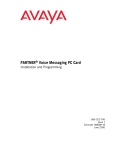
Configurations
1
You can install the PARTNER ACS system in one of three basic configurations, all of which must
be wall-mounted:
■
Stand-alone PARTNER ACS processor module. This configuration does not use a carrier.
■
2-slot carrier, which can hold the PARTNER ACS processor module and one other module.
■
5-slot carrier, which can hold up to five modules, including the PARTNER ACS processor
module. The processor module resides in the center slot. This carrier includes a cover.
In either carrier, only one of the modules must be a PARTNER ACS processor module. The
modules slide into the carrier, which channels power to the system.
System Components
1-7
PARTNER® Advanced Communications System Installation, Programming, and Use
Optional Carriers
CONTROL UNIT
Optional Devices
5-Slot
Carrier
PARTNER ACS
Processor Module
2-Slot
Carrier
(for the control unit)
PARTNER
Grounding Screw
Serial Printer
PARTNER
3000
Contact Closure Jack
SMDR Jack
PC Card Slots (2)
Power LED
PAGE Jack
Paging System
PARTNER
MAIL VS
Voice Messaging
System
Outside Line Jacks (3)
MUSIC-ON-HOLD Jack
(for RCA phono plug)
Extension Jacks (8)
Call Accounting
Terminal (Basic or Plus)
Battery Compartment
ER 3000 ct
PARTN e Adjun
ct Closur
Conta
PUSH
Contact Closure
Adjunct
POWER PLAY RECORD
Optional Modules
SYSTEM PHONES
Magic on Hold deck
Inter
PC Cards
• Backup/Restore
• ASA/DXD (R2.0 or later)
• Software upgrade (R1.0 or later)
• Remote Access (R3.0 or later)
• PARTNER Voice Messaging
com
Inter
com
Ext
.
Featu
re
Conf
Mic
HFA
I
sage
ABC
2
GHI
4
PARTNER
DEF
3
JKL
PQRS
Hold
PARTNER
Mes
1
Tran
sfr
Spkr
5
7
MNO
6
TUV
8
*
WXYZ
9
0
#
PARTNER-34D® Phone
(with optional PARTNER-CA48
Intercom Autodialer)
PFT
PFT
Optional Devices
L
I
L
N
I
E
N
(for extension jacks)
S
E
S
400
MODULE
206
R1.0
MODULE
PFT
On/Off
Feat/P
Conf
Trans
Redial
Mute
1
2 ABC 3 DEF
4 GHI 5 JKL
6 MNO
7PQRS
E
X
T
8 TUV 9 WXYZ
E
Hold
0 OPER
N
S
I
PFT
O
SPARE
L
I
HANDSET
N
N
REFRESH
S
E
S
TransTalk™
Wireless
Phones
Inte
Inte
rcom
Ext
Feat
ure
.
Tran
sfr
sag
e
2
GHI
4
DEF
3
JKL
PQR
Hold
5
S
7
Standard
Phone
Mes
1
ABC
Spk
r
400
Module
206
Module
rcom
Con
f
Mic
HFA
I
PARTNER MAIL
Voice Messaging
System
MNO
6
TUV
8
*
WXY
9
0
Z
#
PARTNER-18D®
Phone
PARTNER
3000
Inte
Ext
Answering
Machine
rcom
.
Inte
rcom
Mes
sag
e
Feat
ure
Spk
r
Con
f
Mic
HFA
I
Tran
sfr
1
Hold
ABC
2
GHI
4
7
Fax Machine
DEF
3
JKL
PQR
5
S
MNO
6
TUV
*
8
WXY
9
0
Z
#
PARTNER-6®
Phone
PUSH
Alert
Inter
com
Inter
com
Ext
Featu
re
Mic
HFA
I
Spkr
Conf
.
Mes
1
sag
e
ABC
Tran
sfr
2
GHI
4
DEF
3
JKL
PQRS
Hold
5
7
MNO
6
TUV
8
*
WXYZ
9
0
#
PARTNER-18®
Phone
Figure 1-1. System Configurations
System Components
1-8
Doorphone
308EC
Module
PassageWay
Adapter
Overview
1
System Modules
A system must contain a processor module. A 2-slot or 5-slot system also contains line/extension
modules.
1
Processor Module
The PARTNER ACS processor module provides the software intelligence that controls the
system’s features. It has jacks for three outside lines, eight enhanced tip/ring extensions, a MusicOn-Hold audio source, a loudspeaker paging system, a grounding screw, a jack that supports an
adjunct for two Contact Closures, and a jack for a call reporting (SMDR) device, such as a printer.
The processor module also has two PC Card slots, a two-color red and green light-emitting diode
(LED), and two AAA user-replaceable batteries. The module provides support for integrated Caller
ID information on system display telephones. The system requires one processor module.
1
Line/Extension Modules
Table 1-3 shows the line/extension modules used in the PARTNER ACS.
Table 1-3. Line/Extension Modules
Name
Line Jacks
Extension Jacks
Additional Information
200
2
0
No longer available
206E
2
6
You can connect telephones and other devices
(such as fax machines and modems) to the
extension jacks.
Green power indicator
No longer available
206EC
2
6
You can connect telephones and other devices
(such as fax machines and modems) to the
extension jacks.
Supports Caller ID1
400E
4
0
Green power indicator
No longer available
400EC
4
0
Green power indicator
Supports Caller ID1
System Components
1-9
PARTNER® Advanced Communications System Installation, Programming, and Use
Table 1-3. Line/Extension Modules–Continued
Name
Line Jacks
Extension Jacks
Additional Information
308EC
Expansion
Module
3
8
Supported in Release 2.0 and later systems. You
can connect telephones and other devices (such
as fax machines and modems) to the extension
jacks.
Green power indicator
Supports Caller ID1
1 To receive Caller ID information, you must first subscribe to the service from your local telephone company (if available)
on a per-line basis. Then connect those lines associated with Caller ID to the line jacks on the module. Any users with
system display telephones who receive calls on Caller ID lines will get Caller ID information.
Hereafter, references to 206 modules include 206E, 206EC, and all 206 modules used with
previous releases of the PARTNER product line. Similarly, references to 400 modules include
400E, 400EC, and all 400 modules used with previous releases of the PARTNER product line. Any
200 modules can be used.
System Batteries
1
The system uses two user-replaceable AAA-size standard alkaline batteries in the processor
module to ensure that system programming and telephone programming settings are not lost in
case of a power failure.
PC Card Slots
1
The processor module has two PCMCIA (Personal Computer Memory Card International
Association) interface slots (hereafter referred to as PC Card slots). You can buy PC Cards to use
in these slots for the following purposes:
■
Use a Backup and Restore PC Card to backup or restore telephone and system programming.
■
Use a PC Upgrade card. After powering down the system, you insert the PC Upgrade Card
and turn the power back on. While the system upgrades, the bicolor (red/green) power LED on
the processor flashes for about 20 seconds; then the power LED becomes steady green. All of
your system and extension programming is saved and ready to work with the new release.
■
Use a PC Card to store Automatic System Answer and Direct Extension Dial (ASA/DXD)
messages. You can insert the card in either PC Card Slot of the processor module, Release
2.0 or later.
■
For PARTNER ACS Release 1.1 or later, use a PARTNER Voice Messaging PC Card to
provide messaging features (store personal greeting and store and retrieve callers’ messages)
for up to four mailboxes.
System Components
1-10
Overview
■
The PARTNER ACS Release 3.0 includes a PARTNER Remote Access PC Card, which allows
you to program the system remotely and perform backup and restore functions. You also can
use the PARTNER Remote Access PC Card to upgrade previous versions of PARTNER ACS
to Release 3.0. You must have additional PARTNER Remote PC-Software to program the
system remotely. You can use this PC Card to program the system locally with a PC.
For information on installing PC Cards, see the instructions that came with the card.
Telephones
1
The telephones supported by the PARTNER ACS fall into two categories:
■
System telephones–telephones specifically designed to work with the PARTNER ACS
■
Single-line telephones–touch-tone or rotary telephones
System Telephones
1
System telephones include the following:
■
PARTNER telephones
– PARTNER-34D
– PARTNER-18D
– PARTNER-18
– PARTNER-6
■
MLS telephones
■
MLC-6
■
TransTalk© 9000-series wireless telephones
Only the PARTNER telephones are discussed in this guide (see Chapter 6, ‘‘Using the
Telephones’’). For information about an MLS, MLC, or TransTalk 9000-series telephone, refer to
the documentation that came with the telephone.
Intercom Autodialers
1
PARTNER telephones support the PARTNER-CA48 Call Assistant Intercom Autodialer at
extensions 10 and 11. The autodialer provides Auto Dial buttons for all of the extensions in your
system. The status lights next to each button also indicate calling activity at that extension. You
can program the Auto Dial buttons for either intercom ringing, voice signaling, or manual signaling.
(Each user can have only one Auto Dial button–either on the system telephone or on the
autodialer–for another extension in the system.) The Auto Dial buttons allow you to dial, signal, or
transfer calls to system extensions with one touch.
System Components
1-11
PARTNER® Advanced Communications System Installation, Programming, and Use
Single-Line Telephones
1
You can also use industry-standard single-line rotary or touch-tone telephones, including feature
telephones with built-in feature buttons and lights, with the system. Certain single-line telephones
are recommended because of their compatibility with the Message Waiting light capability of the
system. See the Customer Support Document provided on the documentation compact disc for a
list of these recommended telephones.
For message waiting capability, you must connect single-line telephones with LEDcompatible message-waiting lights to a processor module, a 308EC module, or to a
Release 3.0 (R3.0) or later 206 module. This message-waiting capability is not supported
for single-line telephones with neon-type message-waiting lights.
Auxiliary Equipment
1
You can connect many types of telecommunications devices to your system without expensive
adapters or additional telephone lines–for example, answering machines, credit card scanners,
and fax machines. Many industry-standard, tip/ring devices work with the system regardless of the
manufacturer.
Auxiliary equipment also includes voice messaging systems. The following are supported by the
PARTNER ACS:
■
PARTNER MAIL VS Voice Messaging System (PMVS)
■
PARTNER Voice Messaging (PVM) PC Card
■
The PARTNER MAIL system
For more information, see Chapter 9, ‘‘Using Auxiliary Equipment’’ or contact your local Authorized
Dealer.
System Components
1-12
Installation
2
Contents
Overview . . . . . . . . . . . . . . . . . . . . . . . . . . . . . . . . . . . . . . . . . . . . . . . . . . . . . . . . . . . 2-1
Evaluating the Environment . . . . . . . . . . . . . . . . . . . . . . . . . . . . . . . . . . . . . . . . . . . . 2-2
Installing the Control Unit . . . . . . . . . . . . . . . . . . . . . . . . . . . . . . . . . . . . . . . . . . . . . . 2-4
■ Wall-Mounting the Control Unit . . . . . . . . . . . . . . . . . . . . . . . . . . . . . . . . . . . . . . . . . 2-4
■ Labeling Jacks . . . . . . . . . . . . . . . . . . . . . . . . . . . . . . . . . . . . . . . . . . . . . . . . . . . . 2-11
■ Grounding the System . . . . . . . . . . . . . . . . . . . . . . . . . . . . . . . . . . . . . . . . . . . . . . 2-12
■ Inserting Batteries in the Processor Module . . . . . . . . . . . . . . . . . . . . . . . . . . . . . . 2-12
■ Initializing the System . . . . . . . . . . . . . . . . . . . . . . . . . . . . . . . . . . . . . . . . . . . . . . . 2-14
■ Checking the LEDs . . . . . . . . . . . . . . . . . . . . . . . . . . . . . . . . . . . . . . . . . . . . . . . . . 2-15
Connecting Lines and Extensions . . . . . . . . . . . . . . . . . . . . . . . . . . . . . . . . . . . . . . 2-16
Installing the Cover . . . . . . . . . . . . . . . . . . . . . . . . . . . . . . . . . . . . . . . . . . . . . . . . . . 2-18
Installing Telephones . . . . . . . . . . . . . . . . . . . . . . . . . . . . . . . . . . . . . . . . . . . . . . . . . 2-18
■ Assembling PARTNER Telephones . . . . . . . . . . . . . . . . . . . . . . . . . . . . . . . . . . . . 2-18
■ Connecting and Testing Telephones . . . . . . . . . . . . . . . . . . . . . . . . . . . . . . . . . . . 2-23
■ Connecting a PARTNER-CA48 Intercom Autodialer . . . . . . . . . . . . . . . . . . . . . . . 2-24
Connecting Auxiliary Equipment . . . . . . . . . . . . . . . . . . . . . . . . . . . . . . . . . . . . . . . . 2-25
2-i
PARTNER® Advanced Communications System Installation, Programming, and Use
2-ii
Installation
2
2
Overview
2
This chapter explains how to install the PARTNER® Advanced Communications System (ACS)
Releases 1.0, 1.1, 2.0, 3.0, or later. The information applies to all releases unless otherwise
specified.
The installation of the PARTNER ACS involves the following:
■
Evaluating the environmental requirements
■
Installing the control unit
■
Connecting lines and extensions
■
Installing telephones
■
Connecting auxiliary equipment
If your company already has modular jacks for all outside lines and extensions, you may be able to
use the existing wiring to install the system hardware and connect telephones to the system
yourself.
Overview
2-1
PARTNER® Advanced Communications System Installation, Programming, and Use
Evaluating the Environment
2
Before you begin the physical installation of the system, you must check that all environmental
factors are within the acceptable ranges, as shown in Table 2-1.
Table 2-1. Environmental Requirements
Specification
Value
Environmental
RequirementsControl Unit
■
■
■
■
■
Mount on a wall at least 2 feet (0.6 meters) from the floor (wall mounting
required)
Locate within 5 feet (1.5 meters) of the network interface jacks and a
properly grounded electrical outlet not controlled by a switch, using
supplied 7-foot (2.1-meter) cords
Operating temperature 32° to + 104°F (0° to + 40°C), not in direct sunlight
Humidity 15%-90%, noncondensing
For proper ventilation and easy replacement of modules, provide the
following minimum clearance around the control unit:
– 5-slot carrier: 1 foot (0.3 meter) clearance at the top and sides and 2
feet (0.6 meter) at the front and bottom
– 2-slot carrier or Stand-alone ACS processor module: 1 foot (0.3
meter) clearance at the front, top and right side, and 2 feet (0.6
meter) at the bottom and left side
Electrical
RequirementsControl Unit
■
Locate in an area free of excess moisture, corrosive gases, dust, and
chemicals
■
U.S. and Canada: 90-264 VAC, 47-63 Hz, 3-prong outlet separate
ground, separately fused at 15 Amps
Other countries: 90-264 VAC (220 VAC fused at 10 Amps)
Grounding to comply with Underwriters Laboratories (UL) 1459:
■
■
a. An insulated grounding conductor that is not smaller in size and
equivalent in insulation material and thickness to the grounded
and ungrounded branch circuit supply conductors, except that it
is green with or without one or more yellow stripes, is to be
installed as part of the circuit that supplies the product or system
Evaluating the Environment
2-2
b.
The grounding conductor mentioned in item A is to be connected
to ground at the service equipment
c.
The attachment-plug receptacles in the vicinity of the product or
system are all to be of a grounding type, and the grounding
conductors serving these receptacles are to be connected to
earth ground at the service equipment
Installation
Table 2-1. Environmental Requirements–Continued
Specification
Value
Requirements for
Out-ofBuilding
Installations
■
Installation of a telephone or other standard (tip/ring) device in another
building requires the following In-Range-Out-Of-Building (IROB)
protectors to protect the control unit and device from electrical surges:
– System phone: two IROB protectors
– Standard phone: two IROB protector plus one carbon block protector
Wiring
■
Installation of a Contact Closure Adjunct controlled device outside the
building requires a 146G Surge Protector-SCL/8 to protect the control unit
from electrical surges
■
System phones: SYSTIMAX® Bulk Nonplenum (DIW) cable, SYSTIMAX
Bulk Plenum (HALAR/HALAR) cable, or at least 2-pair (4-wire) star
("home run" not "loop")
Other standard telecommunications equipment (single-line phones, fax
machines, answering machines, etc.): 1-pair (2-wire) D2R mounting
cords recommended
Bridging adapter: 267F2
Range: 1,000 feet (305 meters) for system phones; 3,000 feet (915
meters) for standard devices
■
■
■
Safety
Requirements
■
U.S.: Meets UL 1459 Issue 2
– Class 2 power standards:
UL 1012 Standard for Safety — Power Supplies
UL 1310 Standard for Safety — Direct Plug-in Transformers
UL 1585 Standard for Safety — Class 2 and Class 3 Transformers
■
Canada: Meets CSA C22.2, No. 0.7-M1985
Evaluating the Environment
2-3
PARTNER® Advanced Communications System Installation, Programming, and Use
Installing the Control Unit
2
The stand-alone processor module or a carrier and its modules are referred to as the control unit.
The control unit must always be wall-mounted.
Before installing the system, be sure you read the safety instructions in the front of this
guide.
WARNING:
There are no customer-serviceable components inside the system modules or carrier. There
are hazardous voltages within that can cause severe or fatal personal injury. DO NOT OPEN
MODULES.
To install the control unit, you must do the following:
■
Wall-mount the control unit.
■
Label the jacks.
■
Ground the system.
■
Insert the batteries into the processor module.
■
Initialize the system.
■
Check the LEDs on the modules.
■
Install the cover (5-slot carrier only).
Wall-Mounting the Control Unit
2
The PARTNER Advanced Communications System can be installed in one of three
configurations:
■
Stand-alone PARTNER ACS processor module
■
2-Slot Carrier, which can hold up to two modules
■
5-Slot Carrier, which can hold up to five modules and includes a cover
Installing the Control Unit
2-4
Installation
Wall-Mounting a Stand-Alone Processor
Module and a 2-Slot Carrier
2
Install the processor module within 5 feet (1.5 meters) of a properly grounded wall outlet (not
controlled by a switch) and the network interface jacks.
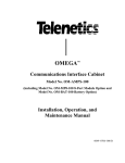
Follow these steps to wall-mount the module(s):
1. Using the enclosed template, mark the screw
locations on the wall.
2. Hold the processor module against the wall
with the line and extension jacks facing left.
Leave at least 1 foot (0.3 meters) clearance at
the top, front, and right side, and at least 2 feet
(0.6 meter) at the bottom and left side
(see Figure 2-1). This allows you to access the
jacks or expand the system with another
module, and ensures adequate ventilation.
Figure 2-1. Processor Module
Clearance
3. Insert a #8 sheet metal screw into the screw
hole at the top of the processor module
(see Figure 2-2).
4. If you are installing a second module, go to
Step 5. If you are not installing a second
module (stand-alone configuration):
a. Insert another #8 sheet metal screw into
the screw hole at the bottom of the module.
b.
c.
Tighten the screws until the mounting
tracks are snug against the wall. There
must be a 3/8 inch (1 cm) gap between the
wall and the rest of the module. Do not
overtighten the screws or the module will
warp and fail to operate.
Go to the next procedure, ‘‘Labeling Jacks’’
on page 2-11.
COMBO
COMBO
Figure 2-2. Screwing in a Processor
Module
Installing the Control Unit
2-5
PARTNER® Advanced Communications System Installation, Programming, and Use
5. Remove the clear plastic protectors from the
connectors on the right side of the wallmounted PARTNER ACS processor module
and the module to be added by grasping the
tabs on the ends of the protector and lifting
(see Figure 2-3).
Tab
Tab
Figure 2-3. Removing the Plastic
Protector
6. Slide the second module onto the PARTNER
ACS processor module, making sure the
mounting tracks interlock (see Figure 2-4).
Mounting
Tracks
Figure 2-4. Module Mounting Tracks
Installing the Control Unit
2-6
Installation
7. Attach the 2-slot carrier to the top right side of
the two modules (see Figure 2-5), properly
engaging the connectors on the modules to the
carrier.
PARTNER
602
ELUDOM
Figure 2-5. Attaching the 2-Slot
Carrier
8. Fasten the carrier to the modules by using the
two #4 screws included with the carrier (see
Figure 2-6).
Figure 2-6. Fastening the 2-Slot
Carrier
Installing the Control Unit
2-7
PARTNER® Advanced Communications System Installation, Programming, and Use
9. Insert the 3-1/2 inch #8 screw into the bottom
of the modules (see Figure 2-7). Tighten it until
the mounting tracks of the PARTNER ACS
processor module are flush against the wall. Do
not overtighten or the module will warp. Then
go to the next procedure, ‘‘Labeling Jacks’’ on
page 2-11.
Figure 2-7. Tightening the Bottom
Screw
Wall-Mounting a 5-Slot Carrier and Modules
2
Install the 5-slot carrier within 5 feet (1.5 meters) of a properly grounded wall outlet (not
controlled by a switch) and the network interface jacks. When you mount the carrier on the wall,
leave at least 1 foot (0.3 meter) of clearance at the top and sides, and 2 feet (0.6 meter) at the
front and bottom to ensure proper ventilation.
The location of each module within the carrier is important; place the modules as
instructed in the following procedure.
For a 5-slot carrier, you need four #12 screws of the appropriate type for the wall and weight of
the control unit (a control unit with four expansion modules and a processor module weighs
approximately 31 pounds or 14 kilograms). The weight of other configurations may vary slightly.
Installing the Control Unit
2-8
Installation
Follow these steps to wall-mount the 5-slot carrier
and modules:
"
1
4
1. Using the enclosed template, mark the screw
locations on the wall (see Figure 2-8). If you are
mounting the carrier on plywood, start four #12
screws supplied with the carrier, leaving the
screw heads extending approximately 1/4 inch
(0.64 cm) from the wall. If you are mounting on
drywall, use wall anchors, which must be
purchased separately.
Figure 2-8. Mounting Screw Locations
2. Before installing any modules, make sure the
clear, plastic protector has been removed from
the connector area on the rear of each module.
To remove the protector, grasp the tabs on the
ends of the protector and lift (see Figure 2-9).
Tab
3. Insert the PARTNER ACS processor module in
the center slot of the carrier.
Tab
Figure 2-9. Removing the Plastic
Protector
Installing the Control Unit
2-9
PARTNER® Advanced Communications System Installation, Programming, and Use
4. In the other slots, from left to right, first install
the 308EC or 206 modules, followed by the 400
or 200 modules. Align the module carefully in
the appropriate slot. For proper engagement of
the connectors, the module must be inserted
straight into the carrier (see Figure 2-10). Once
the module is properly seated, firmly push the
center of the module until the connectors on the
module lock into place. A slight click indicates
the connectors are engaged.
308EC and 206 modules must be to
the left of any 200 and 400 modules.
Carrier Shelf
YES
Carrier Shelf
NO
Figure 2-10. Inserting a Module
CAUTION:
Do not force the module. Use the carrier shelf as a reference and do not tilt, slant, or
rotate the module. If the module does not insert easily, remove it, clear any obstruction,
and reinsert it.
Installing the Control Unit
2-10
Installation
2
Labeling Jacks
After you have mounted the control unit on the wall, you must label the line and extension jacks.
The line jacks are on the top of the modules, and the extension jacks on the bottom
(see Figure 2-11).
Stand-Alone
2-Slot Carrier
ACS
Processor
Module
ACS
Processor 308EC
Module Module
1
4
2
3
5
6
10
10
11
12
11
12
1
2
3
Line
Jacks
Extension
Jacks
5-Slot Carrier
ACS
Processor
Module
2 308EC
Modules
2 308EC
Modules
4
7
1
10
13
5
6
8
9
2
3
11
12
14
15
18
18
26
10
34
42
19
20
19
20
27
28
11
12
35
36
43
44
21
29
13
37
45
22
30
14
38
46
Line
Jacks
Extension
Jacks
13
21
14
14
22
15
15
23
23
31
15
39
47
16
16
24
24
32
16
40
48
17
17
25
25
33
17
41
49
13
Line
Jacks
Extension
Jacks
Figure 2-11. Labeling Jacks
Follow these steps to label the line and extension jacks:
1. Label the line jacks on the processor module, beginning with “1” at the top line jack (see
Figure 2-11).
2. Do one of the following:
a. For a 2-slot carrier, label the line jacks on the other module.
b.
For a 5-slot carrier, label the line jacks on the other modules by starting with the leftmost
module and ending with the rightmost module.
3. Label the extension jacks on the processor module, beginning with “10” at the topmost
extension jack (see Figure 2-11).
4. Do one of the following:
a. For a 2-slot carrier, label the extension jacks on the other module.
b.
For a 5-slot carrier, label the extension jacks on the other modules by starting with the
leftmost module and ending with the rightmost module.
Installing the Control Unit
2-11
PARTNER® Advanced Communications System Installation, Programming, and Use
Grounding the System
2
You ground the system by running a solid copper wire from the processor module to an
appropriate earth ground. Follow these steps to ground the system:
1. Attach one end of a #12 AWG or #14 AWG solid
copper wire to the grounding screw on the
processor module (see Figure 2-12). The length
of the wire must not exceed 35 feet (7.6 meters).
PARTNER
3000
2. Route the wire through the wire manager on the
front of the module.
3. Attach the other end of the wire to the approved
earth ground, such as building steel or a cold
water pipe.
Figure 2-12. Grounding Screw
Locations
Inserting Batteries in the Processor Module
2
The processor module uses two AAA-size standard alkaline batteries to guard against the loss
of system programming in case of a power failure. These batteries retain the system
programming for 45 days to six months, depending on the freshness of the batteries. You should
replace the batteries every year.
CAUTION:
Batteries and battery cover are packaged in a separate box. If you are replacing batteries,
the old batteries must be removed with the power on or the system’s memory will be lost.
Follow these steps to insert the batteries:
1. Locate the battery compartment at the bottom of the PARTNER ACS processor module,
below the extension jacks.
Installing the Control Unit
2-12
Installation
2. Push gently on the battery icon (the locking
latch) and slide the battery icon up to cover the
plus icon; this unlocks the battery assembly
(see Figure 2-13).
3. Remove the battery assembly by gently pulling
the tab at the bottom of the battery compartment
cover.
Locked
Position
Unlocked
Position
Figure 2-13. Locked and Unlocked
Positions
4. Insert two new AAA-size standard alkaline
batteries into the metal battery clips by pushing
them straight in, placing the negative (—) end of
one battery into the bottom clip and the positive
(+) end of the other battery into the top clip
(see Figure 2-14).
Push to
insert
Figure 2-14. Inserting the Batteries
Installing the Control Unit
2-13
PARTNER® Advanced Communications System Installation, Programming, and Use
5. With the locking latch in the unlocked position
(battery icon and “minus” icon visible), slide the
battery assembly into the processor module
along the battery guides on the inside of the
battery compartment (see Figure 2-15). Push
the battery assembly in far enough that the
edges of the assembly slip behind the plastic
housing of the processor module.
Tab
Locking Latch
Figure 2-15. Sliding the Battery
Assembly into the
Processor Module
6. Pressing lightly on the battery icon on the front of the battery assembly, slide the locking
latch downward to secure the assembly in place. The “plus” icon and the battery icon should
now be visible on the front of the battery assembly
(see Figure 2-13).
Initializing the System
2
To initialize the system, you must insert any PC Card before powering up the system. The PC
Cards contain the Backup/Restore, Automatic System Answer/Direct Extension Dial (ASA/
DXD), PARTNER Voice Messaging Basics, and software upgrade features. In Release 3.0, the
PC Card is called the PARTNER Remote Access PC Card.
You must power down the system before you insert or remove a PC Card.
Follow these steps to initialize a system:
1. Insert the PC Card in the PC Card slot on the processor module.
2. If you have a 5-slot carrier, make sure the carrier’s On/Off switch is at the Off (“O”) position.
Installing the Control Unit
2-14
Installation
3. Press the power cord firmly into the power jack on
the carrier or the stand-alone processor module
until the cord locks into place (see Figure 2-16).
Stand-Alone
4. Plug the other end of the power cord into a
properly grounded three-prong wall outlet that is
not controlled by a switch.
5. If you have a 5-slot carrier, move the On/Off
switch to the On (“–”) position.
CAUTION:
The power cord should hang straight down from
the connector for the entire length of the module
or carrier. Do not install the power cord at an
angle to the case or with a loop in it.
2-Slot
6. If this is the initial installation for a Release 3.0
installation, follow these additional steps:
a. Check the LEDs to make sure that the
processor is on steady green for at least 15
seconds.
Figure 2-16. Attaching the Power
Cord
Checking the LEDs
2
After you power up your system, check the green
lights on the fronts of the modules (see Figure 2-17):
■
If a single light is out, power down the control unit,
reseat the module, and then power up the carrier.
■
If multiple lights are out, power down the control
unit, reseat either both modules (2-slot carrier) or
the leftmost module that has a light out (5-slot
carrier), and then power up the carrier.
Lights
PFT
L
PFT
L
I
I
N
N
E
E
S
S
If the lights are still out, see the Customer Support
Document on the accompanying compact disc for
information about whom you should contact.
Figure 2-17. Module LEDs
Installing the Control Unit
2-15
PARTNER® Advanced Communications System Installation, Programming, and Use
Connecting Lines and Extensions
2
If extensions are not wired to any modular jacks, call a qualified service technician.
Use the following procedure to connect lines and extensions:
1. Test for a dial tone at the network interface jacks before connecting outside lines to the
control unit. For the test, connect a tip/ring telephone to the first network interface jack.
a. Lift the handset and listen for a dial tone. (If there is no dial tone, contact your local
telephone company before continuing.)
b.
Repeat for each network interface jack.
2. Connect line cords to the line jacks on the
modules. Start at the top with the line jacks on
the processor module, and then move to the
leftmost module. Fill each module before
moving to the next module to the right
(see Figure 2-18).
3. Route each cord through the wire manager on
the front of the module (see Figure 2-18).
11
12
13
1
2
3
10
11
12
14
15
16
17
13
14
15
16
17
Figure 2-18. Connecting Line Cords to
Line Jacks
Connecting Lines and Extensions
2-16
Installation
4. Connect the free end of each line cord to the
appropriate network interface jack
(see Figure 2-19).
13
55
5
5-
5. Test the lines by plugging a system telephone
into extension jack 10. Press the line button
for each outside line and listen for a dial tone.
55
6. Test the extensions by doing the following:
55
a. Plug a system telephone into the first
extension jack on each module.
b.
7
4
13
8
4
13
5-
49
3
-1
5
55
Press the line button on the telephone for
each outside line and listen for a dial tone.
Figure 2-19. Connecting the Line Cord
to the Network Interface
Jack
7. Connect modular telephone cords to the
extension jacks, starting at the top extension
jack on the processor module
(see Figure 2-20). When that module is full,
move to the leftmost module. Fill each module
before moving on to the next module to the
right.
8. Route each cord through the wire manager on
the front of the module (see Figure 2-20).
9. Connect the free end of each modular
telephone cord to the modular wall jacks for
system extensions.
10. Gather the line and extension cords hanging
below the wire managers of the first two
modules, and twist-tie or wire-wrap them.
Repeat for the remaining cords. For the 5-slot
carrier, place each bundle of wires in the
indentations cut out of the bottom edge of the
carrier.
Figure 2-20. Connecting Cords to
Extension Jacks
Connecting Lines and Extensions
2-17
PARTNER® Advanced Communications System Installation, Programming, and Use
Installing the Cover
2
If you have a 5-slot carrier, it is important to install
the cover to keep the modules dust-free and
properly seated, and the system working efficiently.
Install the cover for the 5-slot carrier by following
these steps (see Figure 2-21):
1. To cover the modules, grasp the upper edges of
the cover and hold it squarely over the control
unit.
2. Place the cover over the modules and make
sure it fits firmly in place.
3. Insert the #6 screw into the tab on the lower
front of the cover. Tighten the screw.
Figure 2-21. Installing the Cover
Installing Telephones
2
After you have installed the control unit and have connected the line and extension cords, you are
ready to install the telephones. Installing the telephones includes assembling, connecting, and
testing the telephone. As desired, you also can connect an Intercom Autodialer to certain
telephones.
Assembling PARTNER Telephones
2
All PARTNER telephones are shipped with a stand for either desk-mounting or wall-mounting the
telephone. For other telephones, see the instructions that are provided with the telephone.
Desk-Mounting the Telephone
Follow these steps to desk-mount a telephone:
1. Gently place the telephone upside down.
Installing the Cover
2-18
2
Installation
2. Route the telephone cord through the hole in
the top center of the stand (see Figure 2-22).
Figure 2-22. Routing the Telephone
Cord
3. Insert the tabs on the narrow end of the stand
into the slots on the inside bottom edge of the
telephone (see Figure 2-24).
Figure 2-23. Inserting the Tabs
Installing Telephones
2-19
PARTNER® Advanced Communications System Installation, Programming, and Use
4. While pressing in the tabs that protrude from
the wide end of the stand, lower the stand to
the telephone (see Figure 2-24).
5. Release the tabs to lock the stand into one of
the three positions provided by the openings
in the back of the telephone. The height of the
stand is adjustable to three positions: low,
medium, and high. The telephone height can
be adjusted by moving the locking tabs to a
different position.
6. Turn the telephone over.
Figure 2-24. Lowering the Stand to the
Telephone
7. Remove the plastic cover from the telephone
(see Figure 2-25). Label the button sheet to
show any programmed lines or button
features, then place the button sheet on the
telephone so the holes fit over the buttons.
Carefully replace the plastic cover.
Inte
8. Adjust the swivel display to the desired angle
(low, medium, or high).
rcom
Inte
rcom
Ext.
Feat
ure
Con
f
Mic
HFA
I
Spk
r
Mes
1
sag
e
AB
Tran
sfr
2
GH
4
I
C
DE
3
JK
PQ
Hol
d
7
5
RS
L
6
TU
8
*
F
MNO
V
WXY
9
0
Z
#
Figure 2-25. Removing the Plastic
Cover
Installing Telephones
2-20
Installation
2
Wall-Mounting
Follow these steps to wall-mount a PARTNER telephone:
1. Reverse the plastic hook that sits in the
earpiece part of the handset cradle (see
Figure 2-26).
2. Turn the telephone upside down. If you have a
tray on the bottom of your telephone, remove
the tray that holds the User Instruction cards by
pressing the tabs on both sides of the tray near
the pull-out tab while sliding the tray straight
out.
Figure 2-26. Reversing the Plastic
Hook
3. Holding the stand with the wide edge down,
mount the stand on the wallplate by using the
keyholes on the base of the stand (see
Figure 2-27).
Figure 2-27. Mounting the Stand on
the Wallplate
Installing Telephones
2-21
PARTNER® Advanced Communications System Installation, Programming, and Use
4. Plug one end of the telephone cord into the jack
in the center of the wall plate (see Figure 2-28).
5. Plug the other end of the telephone cord into
the LINE jack on the bottom of the telephone
(see Figure 2-28).
6. Wrap any excess cord around the cord wrap
posts on the bottom inside of the stand.
With certain telephones, you can wallmount the telephone and use the slide
tray and tray card. Do one of the
following:
■
■
If you have an 18/18D, 34D, or
Intercom Autodialer telephone,
remove the tray from the “desk” end
of the stand and insert it into the
“wall” end. If a 630B wall plate is
used, the tray hangs down from the
telephone.
To
LINE
Jack
Figure 2-28. Plugging in the
Telephone Cord
If you do not use the wall plate with
the 18/18D and 34D telephones, the
tray can slide under the set. To do
this, two mounting holes on the left
and right sides of the stand allow the
tray to slide underneath.
7. To mount the telephone onto the stand, insert
the tabs on the top of the stand into the middle
set of notches on the top edge of the telephone
(see Figure 2-29).
8. Make sure the telephone cord is neatly
wrapped inside the telephone; then rotate the
telephone down until the bottom edge snaps
into position.
Figure 2-29. Mounting the Telephone
onto the Stand
Installing Telephones
2-22
Installation
9. Remove the plastic cover from the telephone
(see Figure 2-30). Label the button sheet to
show any programmed lines or button features.
Then place the button sheet on the telephone
so the holes fit over the buttons. Carefully
replace the plastic cover.
10. Make sure the swivel display is set to the lowest
position.
Figure 2-30. Removing the Plastic
Cover
Connecting and Testing Telephones
2
Follow these steps to connect and test a telephone:
1. To connect a telephone, plug the modular
telephone mounting cord into a modular wall
jack or directly into a module extension jack
(see Figure 2-31).
PFT
To install two telephones (or other
devices) on a single extension jack,
see ‘‘Combination Extensions’’ on
page 9-2.
4
L
I
N
5
E
S
6
7
L
I
N
E
S
206
1
2
3
MODULE
206
MODULE
Ext.
Intercom
+
–
Mic
10
11
12
Message
Intercom
Feature
Conf
Transfr
HFAI
Spkr
Hold
ABC
DEF
1
2
3
GHI
JKL
MNO
4
5
6
PQRS
TUV
WXYZ
7
8
9
*
0
#
PFT
18
19
PFT
E
X
T
2. Test the power and lights on a system
telephone:
PFT
20
21
22
23
E
N
S
I
O
N
S
24
25
26
27
28
29
E
X
13
T
E
N
S
I
O
N
S
14
15
16
17
a. While the telephone is idle, press and hold
the # button for five seconds.
b.
Before releasing the # button, lift the
handset.
Figure 2-31. Plugging in Telephone
Cords
All lights should light, the ringer should
sound, and (on system display telephones
only) a test pattern should appear on the
display. If these do not occur, call for
support as instructed on the inside front
cover of this guide.
c.
Replace the handset; the telephone is now
in normal operating mode.
Installing Telephones
2-23
PARTNER® Advanced Communications System Installation, Programming, and Use
Connecting a PARTNER-CA48 Intercom Autodialer 2
You can connect a PARTNER-CA48 Intercom Autodialer to a PARTNER telephone at an
operator’s extension. The Intercom Autodialer is shipped with an adapter, a D8W line cord, a
power cord, a power unit, and a button-labeling sheet.
You can wall-mount the Intercom Autodialer to work next to a wall-mounted system
telephone. See the instructions provided with the Autodialer.
Follow these steps to connect an Intercom Autodialer to a PARTNER telephone:
1. Plug the adapter into the wall jack
(see Figure 2-32).
2. Plug one end of the D8W line cord into
the J1 jack on the adapter
(see Figure 2-32).
3. Plug the other end of the D8W line cord
into the IN jack on the bottom of the
Autodialer (see Figure 2-32).
Adapter
D8AC Cord
D8W Cord
Ext.
Intercom
4. Plug the blue-tinted connector (labeled
D8AC) of the power cord into the jack
on the power unit.
CAUTION:
Use only the power unit supplied
with the PARTNER-CA48
Intercom Autodialer.
5. Plug the other end (clear tinted) of the
power cord into the J2 jack on the
adapter.
6. Plug the power unit into an electrical
outlet.
7. Plug the telephone’s modular
telephone cord (LINE jack) into the
OUT jack on the bottom of the
Autodialer.
Installing Telephones
2-24
Message
Intercom
+
–
Feature
Conf
Mic
HFAI
Transfr
Spkr
Hold
ABC
1
GHI
2
JKL
DEF
3
MNO
4
5
6
PQRS
TUV
WXYZ
7
8
9
*
0
#
Modular
Telephone
Cord
Figure 2-32. Connection of Cords for the
Intercom Autodialer
Installation
8. Place the Autodialer on the desk to the
right of the telephone
(see Figure 2-33).
9. Remove the plastic cover from the
autodialer and label the button sheet
extension numbers and corresponding
persons’ names. Place the button
sheet on the Autodialer, and carefully
replace the plastic cover.
Interc
om
Interc
om
Ext.
Fea
ture
Co
nf
Mic
HF
AI
Sp
kr
Me
1
ssag
e
ABC
Tra
nsf
r
2
GH
4
I
DEF
3
JKL
PQ
Ho
ld
7
5
RS
MN
6
TUV
8
*
O
WX
9
0
YZ
#
10. Adjust the height of the Autodialer to
match the system telephone.
If you unplug the telephone
connected to an Autodialer, you
must reset the Autodialer. To do
so, unplug the D8W line cord
(connected to the IN jack on the
bottom of the Autodialer) from
the J1 jack on the adapter; then
plug it back in.
Connecting Auxiliary Equipment
Figure 2-33. System Telephone and
Intercom Autodialer
2
You can connect many types of telecommunications devices to your system without expensive
adapters or additional telephone lines–for example, answering machines, credit card scanners,
and fax machines. Many tip/ring, single-line devices work with the system regardless of the
manufacturer. See Chapter 9, ‘‘Using Auxiliary Equipment,’’ for further details about connecting
auxiliary equipment, including voice messaging systems.
Connecting Auxiliary Equipment
2-25
PARTNER® Advanced Communications System Installation, Programming, and Use
Connecting Auxiliary Equipment
2-26
Initial System Programming
3
Contents
Overview . . . . . . . . . . . . . . . . . . . . . . . . . . . . . . . . . . . . . . . . . . . . . . . . . . . . . . . . . . . 3-1
System Programming Basics . . . . . . . . . . . . . . . . . . . . . . . . . . . . . . . . . . . . . . . . . . . . 3-1
Using System Programming . . . . . . . . . . . . . . . . . . . . . . . . . . . . . . . . . . . . . . . . . . . . 3-2
■ Programming Overlays
. . . . . . . . . . . . . . . . . . . . . . . . . . . . . . . . . . . . . . . . . . . . . . 3-2
■ Button Locations . . . . . . . . . . . . . . . . . . . . . . . . . . . . . . . . . . . . . . . . . . . . . . . . . . . . 3-4
■ Programming Mode . . . . . . . . . . . . . . . . . . . . . . . . . . . . . . . . . . . . . . . . . . . . . . . . . 3-5
■ Changing Programming Type . . . . . . . . . . . . . . . . . . . . . . . . . . . . . . . . . . . . . . . . . . 3-6
■ Remote Programming and Local PC Programming . . . . . . . . . . . . . . . . . . . . . . . . . 3-6
Using Centralized Telephone Programming . . . . . . . . . . . . . . . . . . . . . . . . . . . . . . . . 3-6
Setting the Date, Day, and Time . . . . . . . . . . . . . . . . . . . . . . . . . . . . . . . . . . . . . . . . . 3-7
■ Considerations . . . . . . . . . . . . . . . . . . . . . . . . . . . . . . . . . . . . . . . . . . . . . . . . . . . . . 3-7
■ System Date (#101) . . . . . . . . . . . . . . . . . . . . . . . . . . . . . . . . . . . . . . . . . . . . . . . . . 3-8
■ System Day (#102), Release 2.0 and Earlier . . . . . . . . . . . . . . . . . . . . . . . . . . . . . . 3-8
■ System Time (#103) . . . . . . . . . . . . . . . . . . . . . . . . . . . . . . . . . . . . . . . . . . . . . . . . . 3-9
■ Automatic Daylight/Standard Times (#126)–Release 3.0 or Later . . . . . . . . . . . . . 3-9
Assigning Lines . . . . . . . . . . . . . . . . . . . . . . . . . . . . . . . . . . . . . . . . . . . . . . . . . . . . . 3-10
■ Number of Lines (#104) . . . . . . . . . . . . . . . . . . . . . . . . . . . . . . . . . . . . . . . . . . . . . 3-10
■ Key Extensions . . . . . . . . . . . . . . . . . . . . . . . . . . . . . . . . . . . . . . . . . . . . . . . . . . . . 3-11
■ Pooled Extensions (Release 2.0 or later) . . . . . . . . . . . . . . . . . . . . . . . . . . . . . . . . 3-12
Customizing Extensions. . . . . . . . . . . . . . . . . . . . . . . . . . . . . . . . . . . . . . . . . . . . . . . 3-12
■ Copy Settings (#399) . . . . . . . . . . . . . . . . . . . . . . . . . . . . . . . . . . . . . . . . . . . . . . . 3-13
■ Changing Settings to Support
PBX or Centrex Services . . . . . . . . . . . . . . . . . . . . . . . . . . . . . . . . . . . . . . . . . . . . 3-14
Emergency Phone Number List (#406) . . . . . . . . . . . . . . . . . . . . . . . . . . . . . . . . . . . 3-15
■ Considerations . . . . . . . . . . . . . . . . . . . . . . . . . . . . . . . . . . . . . . . . . . . . . . . . . . . . 3-15
■ Programming . . . . . . . . . . . . . . . . . . . . . . . . . . . . . . . . . . . . . . . . . . . . . . . . . . . . . 3-15
3-i
PARTNER® Advanced Communications System Installation, Programming, and Use
3-ii
Initial System Programming
Overview
3
3
3
After you install the system hardware, you must program basic system settings, assign lines, and
customize extensions. To do this, you must understand the basics of programming.
System Programming Basics
3
After the control unit is installed, you set up the system by using a combination of the following two
types of programming. Use the System Planning Guide when programming.
■
System Programming allows you to customize the system to meet the needs of your
business. When the system is first installed, it uses factory settings that reflect the most
commonly used options. You can change system settings as needed.
You can perform System Programming from extension 10 or extension 11. Because an
extension cannot be in programming mode and handle calls at the same time, you should use
extension 11 for programming. By doing so, you can program without disrupting call handling
at extension 10.
■
Telephone Programming allows telephones to be customized to meet individual users’
needs. There are two types of Telephone Programming, depending from where you program.
– Centralized Telephone Programming–programming individual telephones from extension
10 or 11.
– Extension Programming–programming an individual system telephone from the
extension to which it is connected.
You need a system display telephone for System and Centralized Telephone Programming. If you
have any 34-button telephones in the system, you must use a 34-button display telephone to
program since an 18-button telephone cannot be used to program a 34-button telephone. Also, if
your system has both PARTNER and MLS telephones, you should use a PARTNER display
telephone at the programming extension.
The PARTNER ACS Release 3.0 includes a PARTNER Remote Access PC Card, which
allows you to program the system remotely or locally from a PC and perform backup and
restore functions. The PARTNER Remote Access PC Card is a PCMCIA card that can
also be used to upgrade previous versions of PARTNER ACS to Release 3.0. You must
have additional PARTNER Remote PC-Software to program the system remotely.
Overview
3-1
PARTNER® Advanced Communications System Installation, Programming, and Use
Programming procedures use line and extension numbers. The line number represents the line
jack on a module to which the outside line is connected. The extension number represents the
extension jack on a module to which the system telephone or tip/ring device is connected.
If you are installing a voice messaging system with the PARTNER ACS, you must assign
the voicemail ports to Hunt Group 7 to avoid having the voicemail ports answering all calls
immediately. See ‘‘To Program a VMS’’ on page 9-40.
Using System Programming
3
System Programming changes settings for the system as a whole, or for individual lines, pools, or
extensions. You can also use System Programming to set up dialing restrictions, define groups, or
set up auxiliary equipment. Refer to the filled-out System Planner when you are changing system
settings, and be sure that any changes in programming are recorded there.
Programming Overlays
3
To do System Programming, you place a Programming Overlay over the dialpad of the system
display telephone at extension 10 or 11. (Overlays are provided with the system documentation.)
Figure 3-1 shows the Programming Overlays for the PARTNER-34D and PARTNER-18D
telephones.
During System Programming, the normal functions of several buttons on the display telephone at
extension 10 or 11 change. For example, the left i button becomes s and the
right i button becomes c. The Programming Overlay identifies these buttons.
You use the following special buttons while programming:
■
N and P cycle forward and backward through the programming
procedures. You can use these buttons to select a procedure.
(If a procedure instructs you to press N + P, pressing these buttons one
after the other enables you to repeat the current programming procedure.)
■
n and p cycle forward and backward through a procedure’s parameters. A
parameter is typically an outside line, a pool, an extension, or a telephone list entry.
■
D and d cycle forward and backward through the valid entries. These buttons
work only for fixed data, such as a line or extension number. They do not work for variable data
such as date, time, password, telephone numbers, or doorphone assignments.
■
r returns the current setting to the factory setting. When you are programming Line
Assignment (#301), pressing r removes lines from an extension; when you are
programming Pool Extension Assignment (#314), pressing r removes pools from an
extension.
■
e ends an entry of variable length, such as a telephone number in an Allowed Phone
Number List.
■
s starts the System Programming process.
Using System Programming
3-2
Initial System Programming
■
c starts the Centralized Telephone Programming process (to customize individual
telephones centrally from extension 10 or 11).
■
■
f, when followed by 00, enters or exits programming mode.
w enters a “wildcard” (a character that matches any digit dialed) in telephone numbers in
Allowed Phone Number Lists (#407), Disallowed Phone Number Lists (#404), and the
Forced Account Code List (#409).
Y
GG
HH
Next
Procedure
U
Next
Item
V
II
Next
Data
W
Prev
Procedure
Prev
Item
JJ
FF
EE
DD
Remove
X
Prev
Data
Enter
Q
R
S
T
CC
BB
M
N
O
P
AA
Z
G
H
I
J
K
L
B
C
D
E
F
A
System
Central Tel
Program
Program
Message
Feature
Next
Procedure
Next
Item
Next
Data
Remove
Prev
Procedure
Prev
Item
Prev
Data
Enter
Wild
PARTNER 34D
System
Central Tel
Program
Program
Message
Feature
Wild
PARTNER 18D
Figure 3-1. Programming Overlays
Using System Programming
3-3
PARTNER® Advanced Communications System Installation, Programming, and Use
3
Button Locations
When you program from a PARTNER telephone at extension 10 or 11, the button you press on the
telephone at the programming extension may be in a different location on the telephone being
programmed. Figure 3-2 on page 3-4 shows the relative location of buttons on each PARTNER
telephone.
For example, the button labeled E on the PARTNER-34D telephone in Figure 3-2 is in the bottom
row. The equivalent button on the PARTNER-18D telephone is in the leftmost position of the
second row from the bottom. If your system has a mix of PARTNER and MLS telephones, see
Appendix D, ‘‘Programming Mixed Telephone Types,’’ for information about programming from a
PARTNER to an MLS telephone or from an MLS to a PARTNER telephone.
PARTNER-34D Phone
Q
R
S
N
O
P
G
H
I
J
K
A
B
C
D
E
M
T
Ext.
Intercom
Intercom
PARTNER-6 Phone
Q
R
S
T
M
N
O
P
I
J
K
L
E
F
G
H
A
B
C
D
Ext.
Message
Intercom
Figure 3-2. Button Locations on PARTNER Telephones
Using System Programming
3-4
F
Message
PARTNER-18D/18 Phone
Intercom
L
C
D
A
B
Intercom
Intercom
Ext.
Message
Initial System Programming
Programming Mode
3
When you are ready to program a system or telephone feature, you must enter programming
mode. Follow these steps to enter programming mode.
1. Place the Programming Overlay over the dialpad of the system display telephone at extension
10 or 11.
2. To enter programming mode, press f00. A display similar to the following appears:
PROGRAM EXTENSION 10
(If you are programming from extension 11, “11" appears instead of “10.”)
3. Press s. A display similar to the following appears:
10 Enter Extension Name
This display is for the Extension Name Display feature. When you are entering System
Programming mode, skip it by moving on to Step 4.
4. Press s again. A display similar to the following appears:
SYSTEM PROGRAM
5. Specify a programming procedure in one of two ways:
■
Direct Method: Dial the code for that procedure. System Programming procedures in this
guide are identified by a # and a three-digit code (for example, System Date is #101). This
method is best when you are using only a few procedures during a programming session
and you know the codes.
■
Cycle Method: Cycle through the procedures in numerical order. Press N and
P to cycle forward and backward through the programming procedures. This
method is best when you are using multiple procedures during a programming session, or
if you do not know the codes.
6. To exit programming mode, you can press f00. Or you can lift the handset and then
place it back in the cradle.
You can talk on the telephone while you program. This is useful if you call for support
while programming. However, you must call before you enter programming mode,
and you must use the handset to talk, not the speaker and microphone.
Using System Programming
3-5
PARTNER® Advanced Communications System Installation, Programming, and Use
Changing Programming Type
3
When you are in programming mode, you can move between System Programming and
Centralized Telephone Programming. To change to Centralized Telephone Programming when you
are in System Programming, press c. To move back to System Programming when
you are in Centralized Telephone Programming, press c, then s.
Remote Programming and Local PC Programming
3
Users of Partner ACS Release 3.0 can perform Remote Programming by using Partner ACS
Remote Administration software, which is available separately or locally from a PC (except for the
Hong Kong Release 3.0 version.) For more information about remote programming, see the
instructions that come with the software.
Using Centralized Telephone Programming
3
Use Centralized Telephone Programming from extension 10 or 11 to program features or store
telephone numbers for individual extensions. All features that can be programmed at an extension
can also be programmed by using Centralized Telephone Programming. Most features also can be
programmed on a system telephone at the user’s extension, except for the following:
■
Automatic Line Selection, Line Ringing, and Call Screening (F25) always must be
programmed by using Centralized Telephone Programming.
■
If an extension has a single-line telephone, you must program all features for the extension by
using Centralized Telephone Programming.
■
If an extension has a non-display system telephone, you must use Centralized Telephone
Programming to program Extension Name Display for the extension.
During Centralized Telephone Programming, the display telephone at extension 10 or 11 takes on
the characteristics of the telephone being programmed, including any System Programming
settings and lines assigned to the telephone. See ‘‘Using System Programming’’ on page 3-2 for
more information about System Programming and the use of overlays.
To program a telephone from extension 10 or 11, follow these steps:
1. Place the Programming Overlay over the dialpad of the system display telephone at extension
10 or 11.
2. Press f00. A display similar to the following appears:
PROGRAM EXTENSION 10
(If you are programming from extension 11, “11" displays instead of “10.”)
3. Press s. A display similar to the following appears:
10 Enter Extension Name
This display is for the Extension Name Display feature. Skip to Step 4.
Using Centralized Telephone Programming
3-6
Initial System Programming
4. Press s again. The display reads:
SYSTEM PROGRAM
5. Press c. A display similar to the following appears:
CENTRAL TELEPHONE PROG
Extension:
6. Dial the extension number of the telephone to be programmed.
The green lights next to buttons on which lines or pools are assigned show the current Line
Ringing settings. The remaining buttons can be programmed with telephone numbers,
extension numbers, or system features.
7. At this point, program the features that must use Centralized Telephone Programming.
8. To change the settings for another extension, press c; then dial the new extension
number.
9. To exit programming mode, you can press f00, or lift the handset and place it back in
the cradle.
Setting the Date, Day, and Time
3
After supplying power to the control unit, use the following procedures to set the system clock:
■
System Date (#101) to set the month, day, and year
■
System Day (#102) to set the day of the week (for Release 2.0 and earlier systems)
■
System Time (#103) to set the hour and minutes
■
Automatic Daylight/Standard Times (#126) to automatically update the system clock
Turn this feature off if you live in an area without daylight savings time.
Considerations
3
■
Backup Programming–Automatic (#123) uses the System Date and System Time to
schedule the automatic backups.
■
Backup Programming–Automatic (#123) and Backup Programming–Manual (#124) do
not back up the System Date, the System Day, or the System Time.
■
Restore Programming (#125) does not restore the System Date, System Day, or System
Time.
■
Be sure that the System Date, System Day, and System Time are set correctly before using
backup procedures.
Setting the Date, Day, and Time
3-7
PARTNER® Advanced Communications System Installation, Programming, and Use
System Date (#101)
3
Use this feature to set the month, day, and year. The system displays only the month and day on
display telephones when the telephone is idle; the month, day, and year print on SMDR call
reports.
Considerations
■
3
The System Date date-stamps the backup files when you use Backup Programming.
3
Programming
To change the System Date:
1. Press f00ss#101 at extension 10 or 11.
2. Enter today’s date in the form “mmddyy” (month, day, and year), including leading zeros for
single-digit months or days. For example, to enter April 26, 2001, press 042601. A
display similar to the following appears:
System Date
Data 042601
3. Select another procedure, or exit programming mode.
System Day (#102), Release 2.0 and Earlier
3
Use this feature to set the day of the week that appears on system display telephones.
System Day is not applicable to Release 3.0 or later systems. In these releases, the
system calculates the day of the week for you by using System Date (#101).
Programming
3
To change the System Day:
1. Press f00ss#102 at extension 10 or 11.
2. Change the day by pressing D until the day entry you want appears:
■
1 = Sunday (factory setting) ■
2 = Monday
■
3 = Tuesday
■
4 = Wednesday
■
5 = Thursday
■
6 = Friday
Setting the Date, Day, and Time
3-8
Initial System Programming
■
7 = Saturday
3. Select another procedure, or exit programming mode.
System Time (#103)
3
Use this feature to set the time that appears on system display telephones.
Considerations
3
■
Enter the time in 24-hour notation. In this scheme, the hours of the day are 0000
(12 midnight) to 2359 (11:59 p.m.). Since each time must have four digits, use leading
zeros when necessary.
■
The time appears on system display phones as a.m. or p.m. (not in 24-hour notation).
3
Programming
To change the System Time:
1. Press f00ss#103 at extension 10 or 11.
2. Enter a new time in 24-hour notation. For example, to set the time to 2:15 p.m., press
1415.
A display similar to the following appears:
System Time
Data 1415
This time appears on system display phones as 2:15 p.
3. Select another procedure, or exit programming mode.
Automatic Daylight/Standard Times (#126)–Release
3
3.0 or Later
This feature automatically updates the system clock for annual Daylight Savings Time and
Standard Time changes. Turn this feature off if you live in an area without daylight savings time.
Programming
3
To change the status of Automatic Daylight/Standard Time:
1. Press f00ss#126 at extension 10 or 11.
2. Press D until the appropriate value appears:
■
1 = Active (the factory setting) ■
2 = Not Active (the factory setting for Hong Kong Release 3.0 only.)
Setting the Date, Day, and Time
3-9
PARTNER® Advanced Communications System Installation, Programming, and Use
3. Select another procedure, or exit programming mode.
Assigning Lines
3
Use the feature Number of Lines (#104) to determine in Key mode the number of outside lines
that are automatically assigned to all system extensions, or to determine in Hybrid mode the
number of lines assigned to the main pool. After you use the Number of Lines feature, you can use
other features to refine the assignment of lines.
Line assignment is also based upon whether an extension is a Key or Pooled extension. Refine the
line assignment accordingly after you use the Number of Lines feature.
Number of Lines (#104)
3
Use this feature to determine in Key mode the number of outside lines that are automatically
assigned to all system extensions. In Hybrid mode, use this feature to determine the number of
lines assigned to the main pool. (This number does not have to match the actual number of lines
connected at the control unit.) This feature should be used only for initial system setup.
CAUTION:
Do not use Number of Lines (#104) after initial setup.
Considerations
3
■
You can use this feature to tell the system how many lines are actually connected at the
control unit. If you do not use this feature, the line numbers associated with empty jacks are
assigned to telephones as though there were actually lines connected.
■
You can use this procedure to limit the number of lines that are automatically assigned to all
extensions. For example, if there are ten lines connected to the control unit, you can use this
procedure to set the number of lines to eight, so that only the first eight lines are assigned to
all system extensions. You can then use Line Assignment (#301) to assign lines 9 and 10 to
specific extensions.
■
To change pool assignments without affecting other settings, use Pool Line Assignment
(#207) and Pool Extension Assignment (#314).
■
In Hybrid mode, do not use this feature to add lines to the system after initial setup, because it
changes the following features for existing pools back to factory settings:
– Pool Line Assignment (#207)
– Pool Extension Assignment (#314)
– Pool Access Restriction (#315)
– Automatic Line Selection
– Line Ringing
Assigning Lines
3-10
Initial System Programming
■
In Hybrid and Key mode, do not use this feature to add lines to the system after initial setup,
because it changes the following features for individual lines back to factory settings:
– Line Assignment (#301)
– Line Access Restriction (#302)
– Automatic Line Selection
– Line Ringing
■
To change line assignments without affecting other settings, use Line Assignment (#301).
Programming
3
To assign lines to the system at initial system setup:
1. Press f00ss#104 at extension 10 or 11.
2. Enter two digits for the number of outside lines in the system to assign to all extensions or the
main pool. For example, entering 06 means that all extensions are assigned lines 1 through
6 or lines 1 through 6 are assigned to the main pool.
3. Select another procedure, or exit programming mode.
Key Extensions
3
In Key mode, all extensions are Key extensions; in Hybrid mode, extension 10 and any extensions
set to Key by using Line Access Mode (#313) are key extensions.
After you program the Number of Lines, use the following features as needed:
■
Dial Mode (#201) to identify any rotary lines (the default for all lines is “touch-tone”).
■
Line Assignment (#301) to assign lines to specific extensions (if the line was not assigned
using the Number of Lines procedure), to remove lines from some extensions, or to change
the button used to pick up a line at a specific extension.
■
Line Access Restriction (#302) to prevent an extension from receiving and/or making
outside calls on specific lines.
■
Line Ringing (Centralized Telephone Programming) to specify when a line starts ringing at
each extension that has the line.
■
Automatic Line Selection (Centralized Telephone Programming) to specify the order in which
the system selects an available line (intercom or outside) when a user at the extension lifts the
handset or presses S to make a call without first selecting a specific line button.
For extensions with tip/ring telephones, set Automatic Line Selection to intercom first. This
enables tip/ring telephones to access system features, including intercom calling. When users
lift the handsets on tip/ring telephones, they hear intercom dial tone. To access an outside line,
they must dial 9.
Assigning Lines
3-11
PARTNER® Advanced Communications System Installation, Programming, and Use
Pooled Extensions (Release 2.0 or later)
3
If your system will be configured for Hybrid mode, use the features described in this section to
change the assignment of lines in pools, to assign auxiliary pools to pooled extensions, or to
remove the main pool from pooled extensions. If a pooled extension also has an individual line,
see ‘‘Key Extensions’’ above to assign that individual line.
After you program the Number of Lines to assign lines to the main pool, use the following features
as needed:
■
Dial Mode (#201) to identify any rotary lines (the default for all lines is “touch-tone”).
■
Pool Line Assignment (#207) to remove lines from the main pool and assign lines to auxiliary
pools.
■
Line Access Mode (#313) to change a specific extension’s operation from Pooled to Key.
Refer to ‘‘Key Extensions’’ to assign lines to those extensions.
■
Pool Extension Assignment (#314) to remove the main pool, assign auxiliary pools, or
change the location of the button used to select an auxiliary pool at specific extensions. (The
location of the two main pool buttons cannot be changed.)
■
Pool Access Restriction (#315) to prevent an extension from receiving and/or making
outside calls on all lines in specific pools.
■
Line Ringing (Centralized Telephone Programming) to specify when a line or pool starts
ringing at each extension that has the line or pool. Lines are factory-set to Immediate Ring and
pools are factory-set to No Ring.
■
Automatic Line Selection (Centralized Telephone Programming) to specify the order in which
the system selects an available line or pool when a user at the extension lifts the handset or
presses S to make a call.
For extensions with tip/ring telephones, set Automatic Line Selection to intercom first. This
enables tip/ring telephones to access equipment features, including intercom calling. When
users lift the handsets on tip/ring telephones, they hear intercom dial tone. To access a pool,
they can dial the pool access code 880, 881, 882, or 883 or dial 9 to access the first available
line or pool in the sequence.
Customizing Extensions
3
Use the following features to customize an extension:
■
Coverage features
– Line Coverage Extension (#208) to identify an extension as the “owner” of a specific
outside line. A user at the extension can activate Call Coverage or VMS Cover for the
specified line.
– Call Coverage Rings (#116 or #320 [Release 3.0 or later]) to specify the number of
times a call should ring at the owner’s extension before it is sent to the covering extension,
or VMS Cover Rings (#117 or #321 [Release 3.0 or later]) to specify the number of
times a call should ring at the owner’s extension before it is sent to the owner’s voice
mailbox.
Customizing Extensions
3-12
Initial System Programming
■
Caller ID Call Log Line Association (#318) to select the lines to associate with extensions
for logging unanswered calls. Users can view the Caller ID information for unanswered calls
on the telephone’s display panel and autodial the numbers of the unanswered calls.
■
Display Language (#303) to specify the language (English, French, or Spanish) for messages
that appear on a system display telephone.
■
Automatic Extension Privacy (#304) to prevent other extensions with the same line from
joining a call at the extension. Also use this feature for extensions connected to a modem, fax,
or any device whose function can be disrupted by someone trying to join it.
■
Forced Account Code features
– Forced Account Code Entry (#307) to prevent the extension from making an outside call
until a required account code is entered.
– Forced Account Code List (#409) to create a list of valid account codes; this ensures
that only authorized users with valid account codes can make outside calls.
■
Call Waiting (#316) to identify tip/ring telephone extensions that can receive the system (not
the local telephone company) call-waiting tone for a second incoming call when active on a
call.
■
Outgoing Call Restriction (#401) to prevent the extension from making certain types of
outgoing calls on all system lines.
■
Disallowed/Allowed List features
– Disallowed List Assignments (#405) to assign one or more Disallowed Phone Number
Lists to the extension.
– Disallowed Phone Number Lists (#404) to create the lists of outside numbers that
extensions cannot dial.
– Allowed List Assignments (#408) to assign one or more Allowed Phone Number Lists to
the extension.
– Allowed Phone Number Lists (#407) to create the lists of outside numbers that
otherwise-restricted extensions can dial.
■
Pickup Group Extensions (#501), Calling Group Extensions (#502), Night Service Group
Extensions (#504), and Hunt Group Extensions (#505) to place the extension in any of
these groups. See ‘‘Groups of Extensions’’ on page 4-30 for more information.
■
Fax Machine Extensions (#601), Doorphone Extension (#604 and #605), Doorphone
Alert Extensions (#606), AA Extensions (#607), External Hotline (#311), or Hotline (#603)
to identify the extension as one of these equipment types.
Copy Settings (#399)
3
Set up your system by programming one extension for each type of telephone in the system. Then
use Copy Settings (#399) to program other telephones of the same type. For example, you can
program one PARTNER-18D telephone and then copy its settings to any other extensions that
have PARTNER-18D or PARTNER-18 telephones. See ‘‘Copy Settings (#399)’’ on page 4-15 for
more information.
Customizing Extensions
3-13
PARTNER® Advanced Communications System Installation, Programming, and Use
Changing Settings to Support
PBX or Centrex Services
3
Your system may work behind a PBX or Centrex system:
■
PBX services are provided by a private telephone switch.
■
Centrex services are provided by your local telephone company from a Central Office (CO)
outside your premises. These services include the Centrex lines connected to your control unit
modules and some set of features–such as hold, conference, or transfer–available on those
lines. Centrex services may be offered in your area under a different name. For specific
Centrex features to be available to you, your company must subscribe to those features. For
specific information about using Centrex features, see the Centrex documentation provided by
your local telephone company.
Consider the following when setting up your system to work effectively behind a PBX or Centrex
system:
■
Recall setting
■
Dialing restrictions
■
Speed Dial and Auto-Dial numbers
Recall Setting
3
Set the Recall Timer Duration (#107) to match the setting used by your PBX or Centrex system
(usually 800 msec, or “32”). This setting affects the length of a Recall signal sent by the control unit
to access PBX or Centrex services.
Dialing Restrictions
3
Outgoing Call Restriction (#401) is a PARTNER system restriction intended to limit an
extension’s dialing to “inside calls only” (using the i buttons on system telephones) or to
“inside and local calls only” (allowing calls within the PBX or Centrex system and local calls outside
the PBX or Centrex system). However, if users in your system use a dial-out code (9 on most PBX
or Centrex systems) before dialing numbers outside the PBX or Centrex system, the PARTNER
system cannot prevent toll calls for extensions restricted to “inside and local calls only” (unless you
use Disallowed Phone Number Lists (#404) to prevent dialing to specific classes of numbers).
If your PBX or Centrex system includes dialing restrictions, use those instead of the PARTNER
system restrictions. If you have PBX or Centrex dialing restrictions on a line and also program
PARTNER system restrictions, both the PBX or Centrex system and PARTNER system restrictions
apply. However, PARTNER system dialing permissions do not override PBX or Centrex system
restrictions.
Customizing Extensions
3-14
Initial System Programming
Speed Dial and Auto Dial Numbers
3
When you program numbers outside the PBX or Centrex system as Speed Dial and Auto Dial
numbers, include the PBX or Centrex system dial-out code (9 on most systems), followed by one
or more pauses, in the stored number.
Emergency Phone Number List (#406)
3
Use this feature to create a list of up to 10 telephone numbers that all users can dial regardless of
dialing restrictions, provided they have access to an outside line. Typical list entries include fire,
police, and emergency services numbers.
You can use Emergency List entries to override numbers that would otherwise be disallowed. For
example, if you created Disallowed List entries to prevent calls to area code 201, but you want to
allow calls to a specific number in that area code (such as the number of a manager who is on call
after hours), put the number in the Emergency List.
Considerations
3
■
Each telephone number can include up to 12 digits.
■
Enter the telephone number exactly as you would dial it, including any toll prefixes.
■
When programming emergency numbers and/or making test calls to emergency numbers, you
should:
– Remain on the line and briefly explain to the dispatcher the reason for the call before
hanging up.
– Perform such activities in the off-peak hours, such as early morning or late evening.
■
With Release 2.0 and earlier systems, if an extension is programmed for Forced Account
Code Entry (#307), a user at the extension is required to enter an account code before dialing
a number in the Emergency Phone Number List.
■
With Release 3.0 or later systems, users at Forced Account Code extensions can dial
numbers on the Emergency Phone Number List without entering an account code. Users can
make 911 (999 for the Hong Kong Release 3.0 only) calls from the Forced Account Code
extensions without entering the account code as long as 911 (999 for the Hong Kong Release
3.0 only) has been entered into the Emergency Phone Number List.
Programming
3
To create an Emergency Phone Number List:
1. Press f00ss#406 at extension 10 or 11.
Emergency Phone Number List (#406)
3-15
PARTNER® Advanced Communications System Installation, Programming, and Use
2. Select a list entry (01—10). A display similar to the following appears:
Emergency List 03
Data - - - - - - - - - - - -
3. Enter the telephone number.
4. To save the telephone number in memory, you must press e.
5. Do one of the following:
■
To enter other telephone numbers, press n to select a different list entry and repeat
Steps 3 and 4.
■
To change the telephone number you just entered, press r and repeat Steps 3
and 4.
■
To delete the telephone number you just entered, press r.
6. Select another procedure, or exit programming mode.
Emergency Phone Number List (#406)
3-16
Programming System Options
4
Contents
Overview . . . . . . . . . . . . . . . . . . . . . . . . . . . . . . . . . . . . . . . . . . . . . . . . . . . . . . . . . . . 4-1
Abbreviated Ringing (#305) . . . . . . . . . . . . . . . . . . . . . . . . . . . . . . . . . . . . . . . . . . . . 4-2
■ Considerations . . . . . . . . . . . . . . . . . . . . . . . . . . . . . . . . . . . . . . . . . . . . . . . . . . . . . 4-2
■ Programming . . . . . . . . . . . . . . . . . . . . . . . . . . . . . . . . . . . . . . . . . . . . . . . . . . . . . . 4-2
Automatic Extension Privacy (#304) . . . . . . . . . . . . . . . . . . . . . . . . . . . . . . . . . . . . . . 4-2
■ Considerations . . . . . . . . . . . . . . . . . . . . . . . . . . . . . . . . . . . . . . . . . . . . . . . . . . . . . 4-3
■ Programming . . . . . . . . . . . . . . . . . . . . . . . . . . . . . . . . . . . . . . . . . . . . . . . . . . . . . . 4-3
Backup and Restore. . . . . . . . . . . . . . . . . . . . . . . . . . . . . . . . . . . . . . . . . . . . . . . . . . . 4-3
■ Considerations . . . . . . . . . . . . . . . . . . . . . . . . . . . . . . . . . . . . . . . . . . . . . . . . . . . . . 4-4
■ Backup Programming–Automatic (#123) . . . . . . . . . . . . . . . . . . . . . . . . . . . . . . . . 4-4
■ Backup Programming–Manual (#124). . . . . . . . . . . . . . . . . . . . . . . . . . . . . . . . . . . 4-5
■ Restore Programming (#125) . . . . . . . . . . . . . . . . . . . . . . . . . . . . . . . . . . . . . . . . . . 4-6
Call Coverage Rings (#116 or #320) . . . . . . . . . . . . . . . . . . . . . . . . . . . . . . . . . . . . . . 4-7
■ Considerations . . . . . . . . . . . . . . . . . . . . . . . . . . . . . . . . . . . . . . . . . . . . . . . . . . . . . 4-8
■ Programming . . . . . . . . . . . . . . . . . . . . . . . . . . . . . . . . . . . . . . . . . . . . . . . . . . . . . . 4-8
Caller ID Programming. . . . . . . . . . . . . . . . . . . . . . . . . . . . . . . . . . . . . . . . . . . . . . . . . 4-8
■ Caller ID . . . . . . . . . . . . . . . . . . . . . . . . . . . . . . . . . . . . . . . . . . . . . . . . . . . . . . . . . . 4-9
■ Caller ID Log Answered Calls (#317)–
Release 2.0 or Later . . . . . . . . . . . . . . . . . . . . . . . . . . . . . . . . . . . . . . . . . . . . . . . . 4-10
■ Caller ID Call Log Line Association (#318)–
Release 2.0 or Later . . . . . . . . . . . . . . . . . . . . . . . . . . . . . . . . . . . . . . . . . . . . . . . . 4-11
■ Caller ID Log All Calls (#319)–Release 2.0 or Later . . . . . . . . . . . . . . . . . . . . . . . 4-12
■ Caller ID Type (#122) . . . . . . . . . . . . . . . . . . . . . . . . . . . . . . . . . . . . . . . . . . . . . . . 4-13
Call Waiting (#316). . . . . . . . . . . . . . . . . . . . . . . . . . . . . . . . . . . . . . . . . . . . . . . . . . . 4-14
■ Considerations . . . . . . . . . . . . . . . . . . . . . . . . . . . . . . . . . . . . . . . . . . . . . . . . . . . . 4-14
■ Programming . . . . . . . . . . . . . . . . . . . . . . . . . . . . . . . . . . . . . . . . . . . . . . . . . . . . . 4-14
Copy Settings (#399) . . . . . . . . . . . . . . . . . . . . . . . . . . . . . . . . . . . . . . . . . . . . . . . . 4-15
■ Considerations . . . . . . . . . . . . . . . . . . . . . . . . . . . . . . . . . . . . . . . . . . . . . . . . . . . . 4-15
■ Programming . . . . . . . . . . . . . . . . . . . . . . . . . . . . . . . . . . . . . . . . . . . . . . . . . . . . . 4-16
Dialing Restrictions and Permissions. . . . . . . . . . . . . . . . . . . . . . . . . . . . . . . . . . . . . 4-16
■ Allowed Phone Number Lists (#407) . . . . . . . . . . . . . . . . . . . . . . . . . . . . . . . . . . . 4-16
■ Allowed List Assignments (#408) . . . . . . . . . . . . . . . . . . . . . . . . . . . . . . . . . . . . . . 4-18
■ Disallowed Phone Number Lists (#404) . . . . . . . . . . . . . . . . . . . . . . . . . . . . . . . . . 4-18
■ Disallowed List Assignments (#405) . . . . . . . . . . . . . . . . . . . . . . . . . . . . . . . . . . . . 4-21
■ Line Access Restriction (#302)
. . . . . . . . . . . . . . . . . . . . . . . . . . . . . . . . . . . . . . . 4-21
■ Outgoing Call Restriction (#401) . . . . . . . . . . . . . . . . . . . . . . . . . . . . . . . . . . . . . . 4-23
4-i
PARTNER® Advanced Communications System Installation, Programming, and Use
Dial Mode (#201) . . . . . . . . . . . . . . . . . . . . . . . . . . . . . . . . . . . . . . . . . . . . . . . . . . . . 4-24
■ Considerations . . . . . . . . . . . . . . . . . . . . . . . . . . . . . . . . . . . . . . . . . . . . . . . . . . . . 4-24
■ Programming . . . . . . . . . . . . . . . . . . . . . . . . . . . . . . . . . . . . . . . . . . . . . . . . . . . . . 4-24
Display Language (#303) . . . . . . . . . . . . . . . . . . . . . . . . . . . . . . . . . . . . . . . . . . . . . . 4-24
■ Considerations . . . . . . . . . . . . . . . . . . . . . . . . . . . . . . . . . . . . . . . . . . . . . . . . . . . . 4-25
■ Programming . . . . . . . . . . . . . . . . . . . . . . . . . . . . . . . . . . . . . . . . . . . . . . . . . . . . . 4-25
Distinctive Ring (#308) . . . . . . . . . . . . . . . . . . . . . . . . . . . . . . . . . . . . . . . . . . . . . . . . 4-25
■ Programming . . . . . . . . . . . . . . . . . . . . . . . . . . . . . . . . . . . . . . . . . . . . . . . . . . . . . 4-26
External Hotline (#311) . . . . . . . . . . . . . . . . . . . . . . . . . . . . . . . . . . . . . . . . . . . . . . . 4-26
■ Programming . . . . . . . . . . . . . . . . . . . . . . . . . . . . . . . . . . . . . . . . . . . . . . . . . . . . . 4-27
Forced Account Codes . . . . . . . . . . . . . . . . . . . . . . . . . . . . . . . . . . . . . . . . . . . . . . . 4-27
■ Forced Account Code Entry (#307) . . . . . . . . . . . . . . . . . . . . . . . . . . . . . . . . . . . . 4-28
■ Forced Account Code List (#409)
. . . . . . . . . . . . . . . . . . . . . . . . . . . . . . . . . . . . . 4-29
Groups of Extensions. . . . . . . . . . . . . . . . . . . . . . . . . . . . . . . . . . . . . . . . . . . . . . . . . 4-30
■ Calling Group Extensions (#502) . . . . . . . . . . . . . . . . . . . . . . . . . . . . . . . . . . . . . . 4-30
■ Hunt Group Extensions (#505)
. . . . . . . . . . . . . . . . . . . . . . . . . . . . . . . . . . . . . . . 4-31
■ Group Call Distribution (#206) . . . . . . . . . . . . . . . . . . . . . . . . . . . . . . . . . . . . . . . . 4-33
■ Night Service Group Extensions (#504)
. . . . . . . . . . . . . . . . . . . . . . . . . . . . . . . . 4-34
■ Pickup Group Extensions (#501) . . . . . . . . . . . . . . . . . . . . . . . . . . . . . . . . . . . . . . 4-35
Hold Disconnect Time (#203) . . . . . . . . . . . . . . . . . . . . . . . . . . . . . . . . . . . . . . . . . 4-36
■ Considerations . . . . . . . . . . . . . . . . . . . . . . . . . . . . . . . . . . . . . . . . . . . . . . . . . . . . 4-36
■ Programming . . . . . . . . . . . . . . . . . . . . . . . . . . . . . . . . . . . . . . . . . . . . . . . . . . . . . 4-36
Hotline (#603) . . . . . . . . . . . . . . . . . . . . . . . . . . . . . . . . . . . . . . . . . . . . . . . . . . . . . . 4-37
■ Considerations . . . . . . . . . . . . . . . . . . . . . . . . . . . . . . . . . . . . . . . . . . . . . . . . . . . . 4-37
■ Programming . . . . . . . . . . . . . . . . . . . . . . . . . . . . . . . . . . . . . . . . . . . . . . . . . . . . . 4-37
Intercom Dial Tone (#309) . . . . . . . . . . . . . . . . . . . . . . . . . . . . . . . . . . . . . . . . . . . . 4-38
■ Programming . . . . . . . . . . . . . . . . . . . . . . . . . . . . . . . . . . . . . . . . . . . . . . . . . . . . . 4-38
Line Access Mode (#313) . . . . . . . . . . . . . . . . . . . . . . . . . . . . . . . . . . . . . . . . . . . . 4-39
■ Considerations . . . . . . . . . . . . . . . . . . . . . . . . . . . . . . . . . . . . . . . . . . . . . . . . . . . . 4-39
■ Programming . . . . . . . . . . . . . . . . . . . . . . . . . . . . . . . . . . . . . . . . . . . . . . . . . . . . . 4-39
Line Coverage Extension (#208) . . . . . . . . . . . . . . . . . . . . . . . . . . . . . . . . . . . . . . . 4-40
■ Considerations . . . . . . . . . . . . . . . . . . . . . . . . . . . . . . . . . . . . . . . . . . . . . . . . . . . . 4-40
■ Programming . . . . . . . . . . . . . . . . . . . . . . . . . . . . . . . . . . . . . . . . . . . . . . . . . . . . . 4-40
Outside Conference Denial (#109) . . . . . . . . . . . . . . . . . . . . . . . . . . . . . . . . . . . . . 4-41
■ Considerations . . . . . . . . . . . . . . . . . . . . . . . . . . . . . . . . . . . . . . . . . . . . . . . . . . . . 4-41
■ Programming . . . . . . . . . . . . . . . . . . . . . . . . . . . . . . . . . . . . . . . . . . . . . . . . . . . . . 4-41
Pool Programming . . . . . . . . . . . . . . . . . . . . . . . . . . . . . . . . . . . . . . . . . . . . . . . . . . . 4-41
■ Mode of Operation (#198). . . . . . . . . . . . . . . . . . . . . . . . . . . . . . . . . . . . . . . . . . . . 4-41
■ Pool Access Restriction (#315). . . . . . . . . . . . . . . . . . . . . . . . . . . . . . . . . . . . . . . . 4-42
■ Pool Extension Assignment (#314). . . . . . . . . . . . . . . . . . . . . . . . . . . . . . . . . . . . . 4-43
■ Pool Line Assignment (#207) . . . . . . . . . . . . . . . . . . . . . . . . . . . . . . . . . . . . . . . . . 4-45
Recall Timer Duration (#107) . . . . . . . . . . . . . . . . . . . . . . . . . . . . . . . . . . . . . . . . . . 4-46
4-ii
Contents
■
■
Considerations . . . . . . . . . . . . . . . . . . . . . . . . . . . . . . . . . . . . . . . . . . . . . . . . . . . . 4-46
Programming . . . . . . . . . . . . . . . . . . . . . . . . . . . . . . . . . . . . . . . . . . . . . . . . . . . . . 4-46
Remote Administration Password (#730)
–Release 3.0 or Later . . . . . . . . . . . . . . . . . . . . . . . . . . . . . . . . . . . . . . . . . . . . . . . . 4-47
■ Considerations . . . . . . . . . . . . . . . . . . . . . . . . . . . . . . . . . . . . . . . . . . . . . . . . . . . . 4-47
■ Programming . . . . . . . . . . . . . . . . . . . . . . . . . . . . . . . . . . . . . . . . . . . . . . . . . . . . . 4-47
Ring on Transfer (#119) . . . . . . . . . . . . . . . . . . . . . . . . . . . . . . . . . . . . . . . . . . . . . . 4-48
■ Considerations . . . . . . . . . . . . . . . . . . . . . . . . . . . . . . . . . . . . . . . . . . . . . . . . . . . . 4-48
■ Programming . . . . . . . . . . . . . . . . . . . . . . . . . . . . . . . . . . . . . . . . . . . . . . . . . . . . . 4-48
Rotary Dialing Timeout (#108) . . . . . . . . . . . . . . . . . . . . . . . . . . . . . . . . . . . . . . . . . 4-48
■ Considerations . . . . . . . . . . . . . . . . . . . . . . . . . . . . . . . . . . . . . . . . . . . . . . . . . . . . 4-48
■ Programming . . . . . . . . . . . . . . . . . . . . . . . . . . . . . . . . . . . . . . . . . . . . . . . . . . . . . 4-49
Star Code Dial Delay (#410) . . . . . . . . . . . . . . . . . . . . . . . . . . . . . . . . . . . . . . . . . . . 4-49
■ Considerations . . . . . . . . . . . . . . . . . . . . . . . . . . . . . . . . . . . . . . . . . . . . . . . . . . . . 4-50
■ Programming . . . . . . . . . . . . . . . . . . . . . . . . . . . . . . . . . . . . . . . . . . . . . . . . . . . . . 4-50
System Password (#403) . . . . . . . . . . . . . . . . . . . . . . . . . . . . . . . . . . . . . . . . . . . . . 4-51
■ Considerations . . . . . . . . . . . . . . . . . . . . . . . . . . . . . . . . . . . . . . . . . . . . . . . . . . . . 4-51
■ Programming . . . . . . . . . . . . . . . . . . . . . . . . . . . . . . . . . . . . . . . . . . . . . . . . . . . . . 4-51
System Reset–Programming Saved (#728) . . . . . . . . . . . . . . . . . . . . . . . . . . . . . 4-52
■ Considerations . . . . . . . . . . . . . . . . . . . . . . . . . . . . . . . . . . . . . . . . . . . . . . . . . . . . 4-52
■ Programming . . . . . . . . . . . . . . . . . . . . . . . . . . . . . . . . . . . . . . . . . . . . . . . . . . . . . 4-52
System Speed Dial . . . . . . . . . . . . . . . . . . . . . . . . . . . . . . . . . . . . . . . . . . . . . . . . . . 4-53
■ Considerations . . . . . . . . . . . . . . . . . . . . . . . . . . . . . . . . . . . . . . . . . . . . . . . . . . . . 4-53
■ Programming . . . . . . . . . . . . . . . . . . . . . . . . . . . . . . . . . . . . . . . . . . . . . . . . . . . . . 4-54
Toll Call Prefix (#402) . . . . . . . . . . . . . . . . . . . . . . . . . . . . . . . . . . . . . . . . . . . . . . . . 4-54
■ Considerations . . . . . . . . . . . . . . . . . . . . . . . . . . . . . . . . . . . . . . . . . . . . . . . . . . . . 4-54
■ Programming . . . . . . . . . . . . . . . . . . . . . . . . . . . . . . . . . . . . . . . . . . . . . . . . . . . . . 4-55
Transfer Return Programming . . . . . . . . . . . . . . . . . . . . . . . . . . . . . . . . . . . . . . . . . . 4-55
■ Transfer Return Extension (#306) . . . . . . . . . . . . . . . . . . . . . . . . . . . . . . . . . . . . . 4-55
■ Transfer Return Rings (#105)
. . . . . . . . . . . . . . . . . . . . . . . . . . . . . . . . . . . . . . . . 4-56
Unique Line Ringing (#209) . . . . . . . . . . . . . . . . . . . . . . . . . . . . . . . . . . . . . . . . . . . . 4-57
Voice Interrupt On Busy (#312) . . . . . . . . . . . . . . . . . . . . . . . . . . . . . . . . . . . . . . . . . 4-57
■ Considerations . . . . . . . . . . . . . . . . . . . . . . . . . . . . . . . . . . . . . . . . . . . . . . . . . . . . 4-58
■ Programming . . . . . . . . . . . . . . . . . . . . . . . . . . . . . . . . . . . . . . . . . . . . . . . . . . . . . 4-59
4-iii
PARTNER® Advanced Communications System Installation, Programming, and Use
4-iv
Programming System Options
4
4
t
Overview
4
As a System Administrator, after you have initialized the system, you should program features for
the entire system. In addition, you need to be able to back up and restore programming.
Many of these features affect individual extensions, but they are programmed from extension 10 or
11, or from a PC connected to the system. For instructions on system programming, see ‘‘Using
System Programming’’ on page 3-2.
The features are listed alphabetically. When a group of features deals with the same overall
function, they are grouped accordingly (for example, Doorphone Alert Extensions and Doorphone
Extension under “Doorphone Programming”).
Overview
4-1
PARTNER® Advanced Communications System Installation, Programming, and Use
Abbreviated Ringing (#305)
4
Use this feature to activate or deactivate Abbreviated Ringing at the system telephone at a specific
extension. When you are on a call and Abbreviated Ringing is Active, any incoming call rings only
once. The green light next to the line or pool button flashes until the call is answered or the caller
hangs up (or for a transferred call, until the call returns to the transfer return extension). This
feature prevents incoming calls from distracting you when you are busy on another call. To allow
calls to ring repeatedly, set Abbreviated Ringing to Not Active.
Considerations
4
■
Abbreviated Ringing applies only to system telephones.
■
Abbreviated Ringing is typically set to Not Active for operators and others who handle many
calls quickly so they have an audible reminder of incoming calls.
■
Abbreviated Ringing applies to outside, transferred, and intercom calls.
■
The volume of an abbreviated ring is lower than a normal ring.
■
Calls to a busy extension ring at a lower volume than normal even if Abbreviated Ringing is set
to Not Active.
Programming
4
To change the Abbreviated Ringing setting for an extension:
1. Press f00ss#305 at extension 10 or 11.
2. Enter the number of the extension to be programmed.
3. To set Abbreviated Ringing, press D until the appropriate value appears.
■
1 = Active (incoming calls ring once; the factory setting) ■
2 = Not Active (incoming calls ring repeatedly)
4. To program another extension, press n or p until the extension number appears
on the display. Then repeat step 3.
5. Select another procedure, or exit programming mode.
Automatic Extension Privacy (#304)
4
Use this feature to prevent a user from joining an active call at an extension. When Automatic
Extension Privacy is Assigned for an extension, other users cannot join active calls at that
extension. This feature is typically used for single-line telephones and extensions connected to fax
machines, modems, and credit card scanners, which make and receive data calls that should not
be interrupted. This feature can provide the Privacy (F07) function for single-line telephones.
Abbreviated Ringing (#305)
4-2
Programming System Options
Considerations
4
■
If you want to be able to intercept calls routed to an auxiliary device–such as an answering
machine, a voice messaging system, or an auto attendant–make sure Automatic Extension
Privacy is Not Assigned for the auxiliary equipment extension.
■
Single-line telephones and system telephones without a programmed Privacy button cannot
override this feature once it is assigned to an extension.
■
If Automatic Extension Privacy is Assigned at an extension, the green light is lit automatically
after programming the Privacy button to indicate that Privacy is currently active.
■
Automatic Extension Privacy applies only to active calls. Any user can retrieve a held call
unless Exclusive Hold is used.
■
If the voice messaging system extension does not have Automatic Extension Privacy turned
on, other users can bridge onto the call. If a user bridges onto the call, a forward disconnect
signal is sent to the voice messaging system, causing it to disconnect from the call. This
causes the screening extension to be dropped from the call, and the person who bridged onto
the call is now talking to the calling party.
Programming
4
To change the Automatic Extension Privacy setting for an extension:
1. Press f00ss#304 at extension 10 or 11.
2. Enter the number of the extension to be programmed.
3. Press D until the appropriate value displays:
■
1 = Assigned
■
2 = Not Assigned (the factory setting) 4. To program another extension, press n or p until the extension number appears
on the display. Then repeat step 3.
5. Select another procedure, or exit programming mode.
Backup and Restore
4
You should back up the system programming periodically onto a Backup/Restore PC Card,
especially if you are changing the processor module or upgrading the system, or before and after
any major programming changes. You can back up the programming automatically or manually.
Occasionally, you may have to restore programming from the backed-up file.
The PARTNER ACS Release 3.0 includes a PARTNER Remote Access PC Card, which
allows you to program the system and perform backup and restore functions remotely or
locally with a PC.
Backup and Restore
4-3
PARTNER® Advanced Communications System Installation, Programming, and Use
Considerations
4
■
Whenever you change the setting for Backup Programming–Automatic from Not Active to
Active, a backup occurs at the next occurrence of 2:00 a.m. After that, backups are done at
2:00 a.m. on the first day of each month until you change the setting back to Not Active.
■
Slot 2 is recommended for the Backup/Restore PC Card; however, you can use either slot. If
the system detects Backup/Restore PC Cards in both slots when a backup begins, the first slot
is used and the second is ignored.
■
The same Backup/Restore PC Card can be used for both automatic and manual backups,
since the data is recorded in two separate files. An automatic backup replaces the
AUTO.mmddyy file only, and a manual backup replaces the MAN.mmddyy file only.
■
Verify that the System Date (#101), System Day (#102) for systems prior to Release 3.0, and
System Time (#103) are set correctly. These settings are not backed up.
■
Calls continue to be handled normally during an automatic or manual backup.
Backup Programming–Automatic (#123)
4
Use this feature to set up the automatic backup of all programming (except the system date, day,
and time). When Backup Programming–Automatic is set to Active, the information is backed up at
2:00 a.m. on the first day of each month (determined by the system date and time settings) to a
Backup/Restore PC Card.
If Backup Programming–Automatic is Active and an automatic backup fails, a Backup-Failure
Alarm message appears (instead of the system date and time) on the top line of the telephone
display at idle Extensions 10 and 11. The message is one of the following:
■
Backup Failed:Write Prot
■
Backup Failed:Check Card
■
Backup Failed:SystemBusy
■
Backup Failed:InsertCard
See Chapter 11, ‘‘Troubleshooting,’’ for an explanation of these messages and suggested
corrective actions, and for the procedure for clearing the Backup-Failure Alarm message.
Programming
4
To change the setting for Backup Programming–Automatic:
1. Check that only one Backup/Restore PC Card is in the processor module.
2. Press f00ss#166 at extension 10 or 11.
The current setting appears.
Backup and Restore
4-4
Programming System Options
3. To change the setting, press D or d until the setting you want appears, or press
r to return the setting to the factory setting. The possible settings are:
■
1 = Active
■
2 = Not Active (the factory setting) ■
3 = Backup Alarm Cleared
4. Exit programming mode.
For information about using Option 3, Backup Alarm Cleared, see ‘‘Clearing a Backup-Failure
Alarm’’ on page 11-3.
Backup Programming–Manual (#124)
4
Use this feature to manually back up all the programming (except the system date, day, and time)
to a Backup/Restore PC Card.
Programming
4
To begin a manual backup of system settings:
1. Verify that only one Backup/Restore Card is in the processor module.
2. Press f00ss#124 at extension 10 or 11.
If there is a problem, one of the following messages appears (see Chapter 11,
‘‘Troubleshooting,’’ for explanations and corrective actions):
■
Card is Write Protected
■
Insert Valid Card
■
SystemBusy
If there is no problem, the display instructs you to press Enter to begin the backup.
3. Press e.
A status message is displayed indicating that a backup is in progress, and within 30 seconds,
a message appears indicating the result.
If the backup was successful, the new backup information replaces the information in the old
MAN.mmddyy file on the Backup/Restore PC Card, and the.mmddyy extension now reflects
the current date. Backup information created during a manual backup does not overwrite any
AUTO.mmddyy file.
If the backup failed, you see one of the following error messages (see Chapter 11,
‘‘Troubleshooting,’’ for explanations and corrective actions):
■
Backup Failed:Check Card
■
Backup Failed:SystemBusy
Backup and Restore
4-5
PARTNER® Advanced Communications System Installation, Programming, and Use
4. Exit programming mode.
If you exit the procedure before the backup finishes, you do not interrupt the backup,
but you do not see feedback messages on the display.
Restore Programming (#125)
4
Use this feature to reinstate your system and telephone programming (except the System Day,
System Date, and System Time) to the settings saved on a PC Card at the last system backup
(manual or automatic). You should restore the system settings if your system settings become
corrupted, if you make changes and decide you would rather use the former settings, or if you
replace your processor module and want to retain the system settings you had on the previous
processor module. A successful restore takes about five seconds.
When a restore completes successfully, the Restore Complete message appears for two
seconds at idle extensions 10 and 11. Then a System Reset–Programming Saved
(#728) occurs, disconnecting any calls in progress. You should warn users before
beginning a restore, or do the restore during nonbusiness hours.
Considerations
■
4
If the restore is not successful, the display shows Restore Failed or Restore FailedTry Again for two seconds. All calls in progress are disconnected, and all of the system and
telephone programming settings revert to the factory settings.
Using Restore
4
To initiate a restore:
1. If you have a Backup/Restore PC Card installed, skip to Step 2. If you do not have a PC Card
installed, see the PARTNER PC Card Installation Instructions.
2. Press
f00ss#125 at extension 10 or 11.
The top line of the display shows Sys Set Restore or System Settings Restore.
Backup and Restore
4-6
Programming System Options
3. Choose the backup file you want to use for the restore:
■
1 MAN.mmddyy, where “mmddyy” represents the date of the manual backup on this card
■
2 AUTO.mmddyy, where “mmddyy” represents the date of the automatic backup on this
card.
■
If the date of the file (AUTO. mmddyy or MAN. mmddyy) indicates that this is
not the file you intended to use, see the instructions packaged with the PC
Upgrade card for how to install the Backup/Restore PC Card.
■
If the Backup/Restore PC Card is fresh from the factory, and no backups have
been recorded on it yet, the filenames are MAN.****** and AUTO.******,
respectively. You cannot use these files for a restore; they generate the error
message Empty File after you press e in Step 4.
4. Press e to start the restore.
If the system detects an error before beginning the restore, the bottom line of the display
shows one of the following messages (See Chapter 11, ‘‘Troubleshooting,’’ for more
information about these messages):
■
Insert Card or Insert Valid Card
■
Bad File or Bad File-Try Again
■
Incompat Version or Incompatible Versions
■
Empty File
If the system does not detect an error, the restore begins. One of the following occurs:
■
When the restore has completed successfully, the bottom line of the display shows
Restore Complete for two seconds. Then the system resets itself, which means that all
calls in progress are disconnected. You are no longer in System Programming mode.
■
If the restore is not successful, the display shows Restore Failed or Restore
Failed-Try Again for two seconds. All calls in progress are disconnected and all of the
system and telephone programming settings revert to the factory settings. You are no
longer in System Programming mode. Try the restore again.
Call Coverage Rings (#116 or #320)
4
Use this feature to define the number of times intercom, transferred, and outside calls on lines
assigned ownership ring at an extension before they are sent to the covering extension. In Release
2.0 of the system, when you program Call Coverage Rings (#116), it applies to all system
extensions programmed for Call Coverage. In systems of Release 3.0 or later, you can program
Call Coverage Rings (#320) on an individual extension basis.
Call Coverage Rings (#116 or #320)
4-7
PARTNER® Advanced Communications System Installation, Programming, and Use
Considerations
■
4
If an extension has Call Coverage and VMS Cover active, covered calls ring at the covering
extension for the specified number of Call Coverage Rings:
– If the covering extension does not answer, the call is routed to the voice mailbox of the
extension that activated Call Coverage after the specified number of VMS Cover Rings
(#117) or (#321).
– If the covering extension has Do Not Disturb active, the call is routed immediately to the
voice mailbox of the extension that activated Call Coverage.
Programming
4
For Call Coverage Rings (#116)–Release 2.0 only
4
To change the number of times a call rings at an extension before it is sent to the covering
extension:
1. Press f00ss#116 at extension 10 or 11.
2. Enter the number of the extension to be programmed.
3. Enter a different setting (1—9; 2 is the factory setting).
4. To program another extension, press n or p until the extension number appears
on the display. Then repeat step 3.
5. Select another procedure, or exit programming mode.
For Call Coverage Rings (#320)–Release 3.0 or Later
4
1. Press f00ss#320 at extension 10 or 11.
The current ring setting displays.
2. Enter the number of the extension to be programmed.
3. Press D until the appropriate value appears (1—9; 2 is the factory setting).
4. To program another extension, press n or p until the extension number appears
on the display. Then repeat step 3.
5. Select another procedure, or exit programming mode.
Caller ID Programming
4
Although the Caller ID service itself requires no programming, other system features enhance the
use of Caller ID:
■
Caller ID Log Answered Calls
■
Caller ID Call Log Line Association
Caller ID Programming
4-8
Programming System Options
■
Caller ID Log All Calls
■
Caller ID Type
Caller ID
4
Caller ID is available on system display telephones on all lines for which you subscribe to Caller ID
service. Caller ID information is the caller’s telephone number (and name, if available). When
active on a call, you automatically receive Caller ID information for the duration of the call. When
an extension is idle, you receive Caller ID information for a call coming in to your extension. This
feature requires no special programming; however, you must subscribe to Caller ID service (if it is
available) on a per-line basis from your local telephone company and connect Caller ID lines to the
appropriate system modules.
Considerations
4
■
The lines associated with Caller ID must be connected to a line jack on a processor module,
206EC module, 308EC module, or 400EC module.
■
To receive Caller ID information, wait until the second ring before answering the call.
■
Individuals with Call Waiting from the local telephone company do not receive Caller ID
information for the second call.
■
Not all calls on Caller ID lines are displayed. This varies by local telephone company. When
Caller ID information is not captured, the system date and day (default) appears instead.
■
For the Hong Kong Release 3.0 version, the dialed digits will display slightly differently than
shown in the illustrations in this document.
■
The incoming telephone number replaces the system date and time display on system
telephones for the duration of the call. An out-of-area message (- - - - - - - - - - - -) appears if a
call is being dialed from a region that does not support Caller ID. A privacy message (Prove.)
appears if the caller has blocked transmission of Caller ID information.
■
If you use SMDR, telephone numbers of incoming calls print on call reports after the call is
completed, provided you have Caller ID. (Private and out-of-area numbers are reported as “IN”
on call reports.)
■
Any users who have access to Caller ID line(s) receive Caller ID information on their system
display telephones. You can restrict users from viewing Caller ID information by using the
following:
– For ringing calls, you can block Caller ID from being displayed at specific extensions by
restricting access to the Caller ID lines. Use Line Access Restriction (#302) to restrict
access to lines, Pooled Access Restriction (#315) to restrict access to all lines within a
specific pool, or both procedures for pooled extensions that have pools and lines.
– For active calls, you can activate Privacy at your extension to prevent other users from
joining your calls and from accessing the Caller ID information displayed at your extension.
– For held calls, use Exclusive Hold rather than Hold to prevent other users from picking up
your held call and from accessing the Caller ID information associated with the held call.
Caller ID Programming
4-9
PARTNER® Advanced Communications System Installation, Programming, and Use
■
There are two ways to inspect Caller ID lines:
– If you are active on a call, you automatically get Caller ID information for that call.
However, If you want to view Caller ID information for a second call without ending the
active call or putting it on hold, use Caller ID Inspect (see ‘‘Caller ID Inspect (F17)’’ on
page 8-19).
– If you are not active on a call, you can press line buttons to view Caller ID information for
those lines. However, keep in mind that if you pick up the handset, you will join or answer
the call shown on the display.
■
Caller ID information does not display for extensions active on Conference Calls.
■
If you receive a call routed to your extension by Direct Extension Dial, a voice messaging
system, or automated attendant, the Caller ID information is passed to your extension when
you answer the call.
■
If you transfer a call, the Caller ID information is passed to the destination extension.
■
If you send calls for Call Coverage, the Caller ID information is not passed to the covering
extension. “Coverage Call for XX” appears instead so the user at the covering extension can
identify the person for whom the call was originally intended.
■
Caller ID information is displayed if you Join a call; however, you cannot join a call at any
extension that has Privacy activated.
■
Caller ID information is displayed if users pick up calls with Direct Line Pickup–Active Line,
Call Pickup, or Group Pickup.
■
For incoming calls, Caller ID information appears only when a call is audibly alerting at an
extension. This means that extensions with Do Not Disturb activated or extensions that have
lines with Line Ringing set to No Ring do not receive Caller ID information. However, Caller ID
information is displayed once the call is answered or if the line is preselected.
Caller ID Log Answered Calls (#317)–
Release 2.0 or Later
4
Use this feature to program extensions to log answered Caller ID calls so that calls answered at an
individual extension can be viewed in the Caller ID Call Log. Once the feature is activated for an
extension, when a user activates the Caller ID Call Logging and Dialing (F23), all caller ID calls
that are answered by that extension are logged. A telephone symbol (a vertical handset) appears
in the Call Status Display to indicate that the call being viewed has been answered.
Caller ID Log Answered Calls is available on 24-character PARTNER-18D and -34D
display telephones. It is not available for MLS, MLC, Transtalk 9000-Series, or tip/ring
telephones.
Caller ID Log Answered Calls helps to track callers’ telephone numbers. For example, a sales
representative who takes telephone orders could find a number in the log for a caller whose credit
card information was later determined to be invalid.
Caller ID Programming
4-10
Programming System Options
Considerations
■
4
Transfer Return calls that are answered at the return extension are not logged even if Caller
ID Log Answered Calls is set to active.
Programming
4
To program the extension to log answered calls:
1. Press f00ss#317 at extension 10 or 11.
2. Enter the number of the extension to be programmed.
3. Press D until the appropriate value appears:
■
1 = Active (answered calls logged)
■
2 = Not active (answered calls are not logged; the factory setting) 4. To set Call ID Log Answered Calls for another extension, press n or p until the
extension number appears on the display. Then repeat Step 3.
5. Select another procedure, or exit programming mode.
Caller ID Call Log Line Association (#318)–
Release 2.0 or Later
4
Use this feature to associate lines with extensions for the purposes of logging unanswered Caller
ID calls. You can associate multiple lines with an extension and multiple extensions with the same
line. Caller ID calls can be logged only if they ring on an extension that is associated with a line
that has been programmed for Call Logging.
Caller ID Call Log Line Association is available on 24-character PARTNER-18D and -34D
display telephones. It is not available for MLS, MLC, Transtalk 9000-Series, or tip/ring
telephones.
Considerations
4
■
Use Caller ID Call Log Line Association to associate lines with the one extension that will log
all calls. Then use Caller ID Log All Calls (#319) to allow the extension to log all Caller ID
calls on the associated lines.
■
It is not necessary to associate lines and extensions to log unanswered transferred calls.
Unanswered transferred calls are logged automatically.
Programming
4
To associate a line with an extension for the purpose of logging caller ID information:
1. Press f00ss#318 at extension 10 or 11.
2. At the extension prompt, enter the number of the extension to be programmed.
Caller ID Programming
4-11
PARTNER® Advanced Communications System Installation, Programming, and Use
3. At the Line prompt, enter the two-digit line number to be associated with the extension.
4. Press D until the appropriate value appears:
■
1 = Assigned (line is associated with an extension or the extension is associated with a
line)
■
2 = Not assigned (line is not associated with an extension; the factory setting) . Do one
of the following:
– To associate another line with this extension, press n or p until the line
number appears on the display. Then repeat Step 4.
– To associate another extension, press N or P, and begin at Step
2.
5. Select another procedure, or exit programming mode.
Caller ID Log All Calls (#319)–Release 2.0 or Later
4
Use this feature to program a maximum of one extension to log all answered Caller ID calls and all
unanswered Caller ID calls received at any extension on specific lines. You must use the Caller ID
Call Log Line Association (#318) programming procedure to associate lines with the extension
that will log all calls. Then use the Caller ID Log All Calls feature to allow the extension to log all
Caller ID calls on the associated lines. Once the features are activated for an extension, when the
user activates the Caller ID Call Logging and Dialing (F23), all Caller ID calls that are answered
or unanswered by any extension on the associated lines are logged. A telephone symbol (a
vertical handset) appears in the Call Status Display to indicate that the call being viewed has been
answered.
Caller ID Log All Calls is available on 24-character PARTNER-18D and -34D display
telephones. It is not available for MLS, MLC, Transtalk 9000 series, or tip/ring telephones.
The Caller ID Log All Calls feature is useful when a user needs information for all calls received in
the system. For example, a supervisor could use the log for quality assurance by contacting callers
and inquiring about the customer’s satisfaction with the results of the call.
Considerations
4
■
To view the Caller ID Call Log, a Caller ID Call Logging and Dialing button must be
programmed on a button with lights on a system display telephone. (This feature is not
supported on a button without lights.)
■
Transfer Return calls that are answered at the return extension are not logged even if Caller
ID Log All Calls is set to active.
Caller ID Programming
4-12
Programming System Options
Programming
4
To program the extension to log answered calls:
1. Press f00ss#319 at extension 10 or 11.
2. Enter the number of the extension to be programmed.
3. Select another procedure, or exit programming mode.
Caller ID Type (#122)
4
Set this feature for Singapore or USA operation.
In the USA, Caller ID normally displays the number from which the incoming call is coming,
replacing the system date and time display on system telephones for the duration of the call. An
out-of-area message (- - - - - - - - - - - -) displays if a call is being dialed from a region that
does not support Caller ID. A privacy message (Priv.) displays if the caller has blocked
transmission of Caller ID information.
In Singapore, Caller ID normally displays the number from which the incoming call is coming.
When there is no incoming number, the system detects a “P” or an “O” in the “reason for DN
(Directory Number) absence” field, and substitutes the information sent by the local telephone
company central office in the Name parameter field:
■
If the name is supplied, the system displays it.
■
If the name is not supplied, either Priv. or - - - - - - - - - - - - is displayed.
Considerations
4
■
The Caller ID Type you set applies to the entire system.
■
A change to the Caller ID Type setting takes effect when the next Caller ID call comes into the
system.
Programming
4
To change the Caller ID Type setting:
1. Press f00ss#122 at extension 10 or 11.
The system shows the current setting.
2. Press D or d until the appropriate value appears, or press r to return to
the factory setting:
■
1 = USA (the factory setting) ■
2 = Singapore
3. Select another procedure, or exit programming mode.
Caller ID Programming
4-13
PARTNER® Advanced Communications System Installation, Programming, and Use
Call Waiting (#316)
4
Use this feature to activate Call Waiting. When you are on a call and a second intercom,
transferred, or outside call comes in, you hear two beeps to indicate you have a second call waiting
to be answered. Press the switchhook (or Recall or Flash button, if available) to put the current call
on hold and retrieve the second call. To return to the first call, press the switchhook again.
Considerations
4
■
This feature is distinct from the local telephone company’s Call Waiting feature. If you use this
system feature, do not use your local telephone company’s Call Waiting feature.
■
The Call Waiting tone (two beeps) is not repeated.
■
Use Call Waiting only for single-line telephone extensions. Do not assign Call Waiting to
extensions that have fax machines, credit card scanners, modems, or auto attendants
because the call-waiting tone interrupts the data connection.
■
You cannot transfer either party connected by Call Waiting, conference in additional parties, or
use feature codes while both calls are active.
■
Transfer-return, group call distribution, hunt group, and wake-up calls are not considered
incoming calls for this feature.
■
For instructions on using Call Waiting, see ‘‘Answering Calls’’ on page 6-19.
■
Call Waiting does not apply to parked calls.
Programming
4
To change the Call Waiting setting for an extension:
1. Press f00ss#316 at extension 10 or 11.
2. Enter the number of the extension to be programmed.
3. To assign or unassign Call Waiting, press D until the appropriate value appears.
■
1 = Assigned
■
2 = Not Assigned (the factory setting) 4. To program another extension, press n or p until the extension number appears
on the display. Then repeat step 3.
5. Select another procedure, or exit programming mode.
Call Waiting (#316)
4-14
Programming System Options
Copy Settings (#399)
4
Set up your system by programming one extension for each type of telephone in the system. Then
use Copy Settings (#399) to program other telephones of the same type. For example, you can
program one PARTNER-18D telephone and then copy its settings to any other extensions that
have PARTNER-18D or PARTNER-18 telephones.
Use this feature to copy all of the following settings from one extension to another:
■
#116 Call Coverage Rings (Release
2.0 only)
■
#317 Caller ID Call Logging and
Dialing (Release 2.0 and later)
■
#117 VMS Cover Rings (Release 2.0
and earlier)
■
#318 Caller ID Log Answered Calls
■
■
#301 Line Assignment
#320 Call Coverage Rings (Release
3.0 and later)
■
#302 Line Access Restriction
■
■
#303 Display Language
#321 VMS Cover Rings (Release 3.0
and later)
■
#304 Automatic Extension Privacy
■
#401 Outgoing Call Restriction
■
#305 Abbreviated Ringing
■
#405 Disallowed List Assignments
■
#307 Forced Account Code Entry
■
#408 Allowed List Assignments
■
#308 Distinctive Ring
■
#501 Pickup Group Extensions
■
#309 Intercom Dial Tone
■
#502 Calling Group Extensions
■
#310 Automatic VMS Cover
■
#504 Night Service Group
■
#311 External Hotline
■
#505 Hunt Group Extensions
■
#312 Voice Interrupt On Busy
■
#601 Fax Machine Extensions
■
#313 Line Access Mode Line Ringing
■
#607 AA Extensions
■
#314 Pool Extension Assignment
■
#612 Contact Closure Group
■
#315 Pool Access Restriction
■
Automatic Line Selection
■
#316 Call Waiting
■
Line Ringing
Considerations
4
■
This procedure is skipped in the sequence of programming procedures when cycling. To use
this procedure, enter the code (#399) directly.
■
Pooled extension settings can be copied to key extensions, except for extension 10. Key
extension settings can be copied to pooled extensions.
Copy Settings (#399)
4-15
PARTNER® Advanced Communications System Installation, Programming, and Use
Programming
4
To copy the programmed settings from one extension to another of the same type:
1. Press f00ss#399 at extension 10 or 11.
2. At the Extension: prompt, enter the source extension to copy from.
3. At the Data- - - - - - - - - - - - prompt, enter the target extension to copy to–any
extension except the source extension is valid.
4. Do one of the following:
■
To copy the same settings to another extension, enter the new extension number.
■
To copy another extension’s settings, press n or p until the extension number
appears on the display. Repeat Step 3.
5. Select another procedure, or exit programming mode.
Dialing Restrictions and Permissions
4
You can restrict outside calling from an extension by using these various features:
■
Allowed Phone Number Lists
■
Allowed List Assignments
■
Disallowed Phone Number Lists
■
Disallowed List Assignments
■
Line Access Restriction
■
Outgoing Call Restriction
SECURITY ALERT:
While procedures that restrict dialing are very effective, absolute protection against misuse
cannot be guaranteed. System telephones give you more protection against such misuse
than single-line telephones. Therefore, you should install system telephones where
restricting telephone use is important.
Allowed Phone Number Lists (#407)
4
Use this feature to specify telephone numbers that users can dial regardless of other dialing
restrictions, as long as they have access to an outside line. For example, if you restrict an entire
category of calls through Disallowed Phone Number Lists (#404), you can permit calls to a
specific number in that category by placing that number on an Allowed Phone Number List.
Dialing Restrictions and Permissions
4-16
Programming System Options
You can create up to eight Allowed Phone Number Lists of up to 10 telephone numbers each. An
Allowed Phone Number can be up to 12 digits long and may include 0—9, #, *, and h (the
wildcard character, displayed as”!”).
Considerations
4
■
For specific telephone numbers, enter the number exactly as you would dial it. To restrict
dialing numbers in an entire area code, enter that area code exactly as you would dial it (for
example, “800” or “1800”).
■
After programming the Allowed Phone Number Lists, you must use Allowed List
Assignments (#408) to assign the lists to specific extensions.
■
Allowed Phone Number Lists override Disallowed Phone Number Lists (#404) and
Outgoing Call Restriction (#401), but not Line Access Restriction (#302), Pool Access
Restriction (#315), or Night Service Button (#503) with a System Password (#403).
■
The entries you must make to permit or restrict long-distance calls differ depending on the
setting for Toll Call Prefix (#402). This setting tells the system whether a “0” (for operatorassisted calls) or a “1” (for direct-dial calls) is required when users make long-distance calls.
■
If Star Code Dial Delay (#410) is active, after a valid star code is dialed, the system resets the
dialing restrictions to check the number beginning with the first digit after the star code.
■
If you want to go to another programming procedure when entering telephone numbers in a
list, you must press N + P, since entering # and a three-digit code is
considered part of the telephone number.
SECURITY ALERT:
If you are restricting an extension from placing long-distance calls, do not place numbers
beginning with a “0” on an Allowed Phone Number List for the extension. Once a user is
active on an operator-assisted call, the user can avoid dialing restrictions by asking the
operator to dial restricted numbers.
Programming
4
To create a list of Allowed Phone Numbers:
1. Press f00ss#407 at extension 10 or 11.
2. At the List Number: prompt, enter a list number (1—8).
3. At the Entry: prompt, select a list entry (01—10).
4. At the Data- - - - - - - - - - - - prompt, enter the first telephone number.
5. To save the telephone number in memory, press e.
Dialing Restrictions and Permissions
4-17
PARTNER® Advanced Communications System Installation, Programming, and Use
6. Do one of the following:
■
To change the telephone number you just entered, press r and repeat Steps 4 and
5.
■
To delete the telephone number you just entered, press r.
■
To add other telephone numbers to this list, press n and repeat Steps 4 and 5.
■
To create another list, press N + P and go to Step 2.
7. Select another procedure by using N + P, or exit programming mode.
Allowed List Assignments (#408)
4
Use this feature to assign up to eight Allowed Phone Number Lists to a specific extension.You
must use Allowed Phone Number Lists (#407) to create the lists of allowed telephone numbers
before you use this procedure.
4
Programming
To assign Allowed Phone Number Lists to an extension:
1. Press f00ss#408 at extension 10 or 11.
2. Enter the number of the extension to be programmed.
3. Enter the list number (1—8).
4. To assign or unassign the list, press D until the appropriate value appears.
■
1 = Assigned to extension
■
2 = Not Assigned to extension (the factory setting) 5. Do one of the following:
■
To assign or unassign another list to this extension, press n until the list number
appears on the display. Then repeat Step 4.
■
To program another extension, press N + P and begin at Step 2.
6. Select another procedure, or exit programming mode.
Disallowed Phone Number Lists (#404)
4
Use this feature to specify telephone numbers that users cannot dial. For example, you may want
to prevent calls to a specific telephone number or to categories of numbers, such as international
numbers.
You can create up to eight Disallowed Phone Number Lists of up to 10 telephone numbers each. A
Disallowed Phone Number can be up to 12 digits long and may include 0—9, #, *, and h (the
wildcard character, displayed as “!”).
Dialing Restrictions and Permissions
4-18
Programming System Options
4
Considerations
■
After completing this procedure, you must use Disallowed List Assignments (#405) to
assign the Disallowed Phone Number Lists to specific extensions.
■
To restrict dialing specific telephone numbers, enter the telephone number exactly as you
would dial it. For example, to prevent calls to the local number 555-5678, press
5555678.
■
To restrict dialing numbers in an entire area code, enter that area code exactly as you would
dial it (for example, “900,” “1900,” or “0900,” depending on the Toll Call Prefix required). This
setting tells the system whether a “0” (for operator-assisted calls) or a “1” (for direct-dial calls)
is required when you make toll calls.
■
To prevent dialing all telephone numbers in one exchange when a toll prefix is required, see
Table 4-1. (The table uses exchange “976” as the example.)
Table 4-1. Preventing Dialing of Numbers in One Exchange When Toll Prefix Required
■
Entry
Restriction
976
Prevents local calls
1!!!976
Prevents direct-dial calls to all area codes
0!!!976
Prevents operator-assisted calls to all area codes
1976
Prevents direct-dial toll calls in the same area code (needed only when 0
or 1 is required for toll calls in the same area code)
0976
Prevents operator-assisted toll calls in the same area code (needed only
when 0 or 1 is required for toll calls in the same area code)
To prevent dialing all telephone numbers in one exchange when no toll prefix is required, see
Table 4-2. (The table uses exchange “976” as the example.)
Table 4-2. Preventing Dialing of Numbers in One Exchange When No Toll Prefix Required
Entry
Restriction
976
Prevents local calls
!0!976
Prevents calls to area codes with “0” as the second digit, such as 203
!1!976
Prevents calls to area codes with “1” as the second digit, such as 212
■
To prevent international calls, enter the international prefix number, 011.
■
To prevent the use of all star codes, enter * (for touch-tone telephones) and 11 (equivalent
to a * on rotary telephones).
■
To prevent the use of a specific star code (for example, *67 to block Caller ID information),
enter the * plus the 2- or 3-digit code (for touch-tone telephones) or 11 (equivalent to a *
on rotary telephones) plus the 2- or 3-digit code.
Dialing Restrictions and Permissions
4-19
PARTNER® Advanced Communications System Installation, Programming, and Use
– For touch-tone telephones, entering *67 prevents the use of *67 to block Caller
ID information.
– For rotary telephones, entering
ID information.
1167 prevents the use of 1167 to block Caller
■
Allowed Phone Numbers, Emergency Phone Numbers, and Marked System Speed Dial
numbers override the Disallowed List.
■
When a user dials a number that is on a Disallowed List for the user’s extension, the user
hears a reorder tone (fast busy signal) after dialing the part of the number that is stored in the
list (for example, an area code).
■
The entries you must make to permit or restrict toll calls differ depending on the setting for Toll
Call Prefix (#402).
■
If Star Code Dial Delay (#410) is active, after a valid star code is dialed, the system resets the
dialing restrictions to check the number beginning with the first digit after the star code.
■
If you want to go to another programming procedure when entering telephone numbers in a
list, you must press N + P, since entering # and a three-digit code is
considered part of the telephone number.
Programming
4
To create a list of Disallowed Phone Numbers:
1. Press f00ss#404 at extension 10 or 11.
2. At the List Number: prompt, enter a list number (1—8).
3. At the Entry: prompt, select a list entry (01—10).
4. At the Data- - - - - - - - - - - - prompt, enter the first telephone number.
5. To save the telephone number in memory, press e.
6. Do one of the following:
■
To add other telephone numbers to this list, press n to select a different list entry
and repeat Steps 4 and 5.
■
To change the telephone number you just entered, press r and repeat Steps 4 and
5.
■
To delete the telephone number you just entered, press r.
■
To create another list, press N + P and repeat from Step 2.
7. Select another procedure by using N + P, or exit programming mode.
Dialing Restrictions and Permissions
4-20
Programming System Options
Disallowed List Assignments (#405)
4
Use this feature to assign up to eight Disallowed Phone Number Lists to specific extensions.
Considerations
4
■
You must use Disallowed Phone Number Lists (#404) to create the lists of disallowed
telephone numbers before you use this procedure.
■
When a Disallowed Phone Number List is assigned to an extension, the list applies to all lines
to which the extension has access.
Programming
4
To assign Disallowed Phone Number Lists to an extension:
1. Press f00ss#405 at extension 10 or 11.
2. Enter the number of the extension to be programmed.
3. Enter the list number (1—8).
4. To assign or unassign the list, press D until the appropriate value appears.
■
1 = Assigned to extension
■
2 = Not Assigned to extension (the factory setting) 5. Do one of the following:
■
To assign or unassign another list for this extension, press n or p until the list
number appears on the display. Then repeat Step 4.
■
To program another extension, press N + P, and begin at Step 2.
6. Select another procedure, or exit programming mode.
Line Access Restriction (#302)
4
Use this feature to restrict an extension from receiving and/or making outside calls on a specific
line. For example, you may want a secretary to answer calls on a manager’s line, but not to make
any outgoing calls on the line; in this case you can assign the manager’s line to the secretary’s
extension and restrict it to In Only.
This procedure is the most extreme way to restrict dialing. For example, an extension with a line
set to In Only or No Access cannot select the line to dial out–even for numbers on the
Emergency Phone Number List (#406).
Dialing Restrictions and Permissions
4-21
PARTNER® Advanced Communications System Installation, Programming, and Use
Considerations
4
■
For pooled extensions, use Pool Access Restriction (#315) to assign restrictions to all the
lines assigned to a specific pool. (Pool Access Restriction overrides Line Access Restriction.)
For individual lines on pooled extensions, use Line Access Restriction.
■
To prevent an extension from using a line, restrict the line even if it is not assigned to the
extension, so the line cannot be accessed by Direct Line Pickup.
■
If an extension’s access to a line is set to No Access or In Only, the extension cannot place
calls on that line, neither by pressing the line button, nor by using Direct Line Pickup–Idle
Line.
■
If an extension’s access to a line is set to No Access or Out Only, the extension cannot receive
calls on that line that are ringing at other extensions, neither by pressing the line button, nor by
using Direct Line Pickup–Active Line.
■
Caller ID information does not appear for ringing calls on lines programmed for Out Only or No
Access.
■
If a line is assigned to a telephone but is restricted to No Access, the line button LEDs show
calling activity; but the line cannot be used to place or receive calls.
Programming
4
To restrict an extension from making calls on a specific line:
1. Press f00ss#302 at extension 10 or 11.
2. At the Extension: prompt, enter the extension number to be programmed.
3. At the Line: prompt, enter the line number to be restricted at this extension.
The current restriction appears.
4. To change the line restriction for this extension, press D until the appropriate value
appears.
■
1 = No Restriction (calls permitted on that line; this is the factory setting) ■
2 = Out Only (can only make outside calls, not receive them, on that line)
■
3 = In Only (can only receive calls, not make them, on that line)
■
4 = No Access (cannot receive or make calls, but can join calls, receive transferred calls,
or pick up calls on hold on that line)
5. Do one of the following:
■
To restrict another line at this extension, press n or p until the line number
shows on the display. Repeat Step 4.
■
To restrict another extension, press N + P and begin at Step 2.
6. Select another procedure, or exit programming mode.
Dialing Restrictions and Permissions
4-22
Programming System Options
Outgoing Call Restriction (#401)
4
Use this feature to specify the types of outgoing calls that can be made on all lines at an extension.
Considerations
4
■
If the system is connected to a PBX or Centrex system and a dial-out code (usually 9) is
needed to place calls outside the PBX or Centrex system, the control unit may not be able to
prevent calls for extensions restricted to Local Only. If dialing restrictions are needed on
Centrex lines, use Centrex restrictions instead.
■
Outgoing Call Restriction also applies to lines that a user has access to with Direct Line
Pickup–Idle Line.
■
To override this feature, users can dial Marked System Speed Dial numbers and numbers
from an Allowed Phone Number List (#407) and the Emergency Phone Number List
(#406). Also, if a System Password (#403) is defined, MLS system telephone users can enter
it to override restrictions.
■
You can program a button on the system telephone at extension 10 to be used to quickly
change an extension’s Outgoing Call Restriction setting. See Outgoing Call Restriction
Button (#114) for information.
■
If Star Code Dial Delay (#410) is active, the system checks for allowed and disallowed
telephone numbers again, beginning with the first digit after the star code.
■
If you want to restrict the use of star codes, include them in the Disallowed Phone Number
Lists.
Programming
4
To identify the types of outgoing calls that can be made on all lines at an extension:
1. Press f00ss#401 at extension 10 or 11.
2. At the Extension: prompt, enter the number of the extension to be programmed.
3. To change the type of call restriction, press D until the appropriate value appears:
■
1 = No Restriction (can make toll, local, and intercom calls; this is the factory setting.) ■
2 = Inside (intercom) Only
■
3 = Local (intercom and local) Only
For Hong Kong Release 3.0, the values are:
■
1 = No Restriction
■
2 = Inside (intercom) Only. Allows calls to emergency number 999.
■
3 = Local (intercom and local) Only. Cannot dial numbers beginning with 17, 001, or 002.
4. To program another extension, press n or p until the extension number shows on
the display. Repeat Step 3.
5. Select another procedure, or exit programming mode.
Dialing Restrictions and Permissions
4-23
PARTNER® Advanced Communications System Installation, Programming, and Use
Dial Mode (#201)
4
Use this feature to identify individual lines as touch-tone or rotary. Check with your local telephone
company if you are not sure which type of line is being provided to you.
Considerations
4
■
If you are having difficulty using touch-tone telephones on rotary lines, you may need to adjust
the Rotary Dialing Timeout (#108).
■
If the system has rotary lines, you can use Touch-Tone Enable (F08) to send touch-tone
signals over a rotary line (for example, to access bank-by-telephone services).
■
If Dial Mode is set to Rotary, star codes are entered by dialing 11 instead of *. If you have
users at extensions with Outgoing Call Restriction (#401) set to Local Only who are calling
out on lines with the Dial Mode set to Rotary, you should add “11” to an Allowed Phone
Numbers List (#407) and assign the list to these extensions. Otherwise, when the users at the
restricted extensions dial 1 to begin a star code, the system interprets this as an attempt to
place a long-distance call, the call is blocked, and the user hears the reorder tone.
Programming
4
To change the Dial Mode setting for a specific line:
1. Press f00ss#201 at extension 10 or 11.
2. Enter the first line to be programmed.
3. Press D until the appropriate value appears:
■
1 = Touch-Tone line (the factory setting) ■
2 = Rotary line
4. To program another line, press n or p until the line number appears on the
display. Then repeat Step 3.
5. Repeat Steps 3 and 4 for all lines that you want to change.
6. Select another procedure, or exit programming mode.
Display Language (#303)
4
Use this feature to change the language in which display messages appear if the extension has a
system display telephone. The language is set for each extension, so telephones in the same
system can display different languages.
Dial Mode (#201)
4-24
Programming System Options
Considerations
4
If SMDR is used, the call report header is printed in the language specified for extension 10.
Programming
4
To change the Display Language setting for an extension:
1. Press f00ss#303 at extension 10 or 11.
The current Display Language displays.
2. Enter the number of the extension to be programmed.
3. To change the Display Language, press D until the appropriate value appears.
■
1 = English (the factory setting) ■
2 = Spanish
■
3 = French
4. To program another extension, press n or p until the extension number appears
on the display. Then repeat step 3.
5. Select another procedure, or exit programming mode.
Distinctive Ring (#308)
4
Use this feature to determine whether calls should ring at a tip/ring device using the system’s
distinctive ringing patterns–different patterns for outside, intercom, and transferred calls–or
whether all calls to the tip/ring device should ring like outside calls.
Considerations
4
■
Change the setting to Not Active if a tip/ring device such as a modem or answering machine
does not pick up intercom or transferred calls.
■
If distinctive ring is set to Not Active for an extension with both a system telephone and a tip/
ring device, the system telephone continues to use the system’s distinctive ringing patterns,
but all calls ring at the tip/ring device using a single ring burst.
■
The system does not pass distinctive ringing patterns generated by a PBX or central office
through to extensions (regardless of the setting for this feature).
Distinctive Ring (#308)
4-25
PARTNER® Advanced Communications System Installation, Programming, and Use
Programming
4
To change the Distinctive Ring setting:
1. Press f00ss#308 at extension 10 or 11.
2. At the Extension: prompt, enter the number of the extension to be programmed.
3. Press D until the appropriate value appears.
■
1 = Active (outside, intercom, and transferred calls ring differently, using the system’s
distinctive ringing patterns; the factory setting) ■
2 = Not Active (outside, intercom, and transferred calls all ring using a single ring burst)
4. To program another extension, press n or p until the extension number appears
on the display. Repeat Step 3.
5. Select another procedure, or exit programming mode.
External Hotline (#311)
4
Use this feature to identify an external hotline extension. When a user lifts the handset of an
external hotline, a predetermined outside number is dialed automatically. The external number
might be, for example, a frequently called service bureau. The external hotline must be a singleline telephone, not a system telephone, and should not have a dialpad.
After you identify an external hotline extension, you must store the external telephone number for
the hotline extension as Personal Speed Dial code 80.
Considerations
4
■
Under certain conditions of heavy telephone usage, the external hotline may be unable to dial
the programmed number immediately (for example, if many of the tip/ring devices connected
to your system dial out at the same time).
■
You can identify several extensions as external hotlines.
■
Do not assign an external hotline to extension 10, 11, or to the first two extensions of any 206
or 308EC module, which are reserved as power-failure extensions.
■
Use Hotline (#603) to identify an internal hotline extension.
■
Use Line Assignment (#301) to assign outside lines to the external hotline extension, Pooled
Extension Assignment (#314) to assign pools to the external hotline extension, and
Automatic Line Selection to set the extension to select outside lines or pools first.
If your use of the external hotline requires immediate dialing of the programmed number,
assign a line for use only by this extension.
■
Set Line Ringing to No Ring for all lines or pools assigned to the external hotline to prevent
incoming calls from ringing at the extension.
■
Make sure there are no call, line, or pool restrictions assigned to an external hotline.
External Hotline (#311)
4-26
Programming System Options
■
Do not use Station Lock at an external hotline because it will prevent the outside number from
being dialed.
■
Remove external hotlines from Night Service Group Extensions (#504), Calling Group
Extensions (#502), and Hunt Group Extensions (#505).
■
Do not assign Forced Account Code Entry (#307) to the external hotline.
Programming
4
To identify an external hotline extension:
1. Press f00ss#311 at extension 10 or 11.
2. At the Extension: prompt, enter the external hotline extension number.
3. Press D until the appropriate value appears:
■
1 = Assigned
■
2 = Not Assigned (the factory setting) 4. To program another extension, press n or p until the extension number appears
on the display. Repeat Step 3.
5. Select another procedure, or exit programming mode.
To program the external hotline telephone number as Personal Speed Dial code 80:
1. Press f00ssc.
2. Dial the extension number of the external hotline.
3. Press f80.
4. Enter the external hotline telephone number exactly as you would dial it.
5. Continue programming, or exit programming mode.
Forced Account Codes
4
When you set up forced account codes on the system, users at specific extensions must enter an
account code before they can dial outside calls. Setting up forced account codes involves two
features: Forced Account Code Entry and, optionally, Forced Account Code List.
See ‘‘Account Code Entry (F12)’’ on page 8-2 for instructions on entering forced account codes at
a telephone.
Forced Account Codes
4-27
PARTNER® Advanced Communications System Installation, Programming, and Use
Forced Account Code Entry (#307)
4
This feature applies only to system telephones.
Forced Account Code Entry identifies extensions at which users must enter an account code
before making outside calls. The account code can be used to charge telephone calls to a
department or client.
Considerations
4
■
For Release 2.0 or earlier systems, you cannot dial numbers on the Emergency Phone
Number List (#406) until an account code is entered at a Forced Account Code Entry
extension. If a Forced Account Code List exists, the account code must match an entry on the
list for you to get an outside line.
■
For Release 3.0 or later systems, you can dial numbers on the Emergency Phone Number
List (#406) without entering an account code at a Forced Account Code Entry extension. You
can make 911 (999 for the Hong Kong Release 3.0 only) calls from the Forced Account Code
extensions without entering the account code as long as 911 (999 for the Hong Kong Release
3.0 only) has been entered into the Emergency Phone Number List.
■
You can enter account codes manually or by using System Speed Dial numbers, Personal
Speed Dial numbers, or Auto Dialing (but not Marked System Speed Dial numbers).
■
Automatic Line Selection does not apply for an extension programmed with Forced Account
Code Entry; you must manually select a line or pool after entering an account code.
■
Do not assign Forced Account Code Entry to an External Hotline (#311) extension.
■
If a System Password (#403) is required to override dialing restrictions for an extension, you
must enter it before entering the account code.
■
If SMDR is used, the account code assigned to incoming or outgoing calls prints on call
reports. If a Forced Account Code List exists, only valid account codes are printed on the call
report.
■
You do not need a forced account code to answer incoming calls.
Programming
4
To program an extension for Forced Account Code Entry:
1. Press f00ss#307 at extension 10 or 11.
2. At the Extension: prompt, enter the number of the extension to be programmed.
3. Press D until the appropriate value appears:
■
1=Assigned
■
2=Not Assigned Forced Account Codes
4-28
Programming System Options
4. To program another extension, press n or p until the extension number shows on
the display. Then repeat Step 3.
5. Select another procedure, or exit programming mode.
Forced Account Code List (#409)
4
Forced Account Code List lets you create a list of up to 99 account code verification entries for
extensions that are forced to enter account codes. Once a list is created, any user at an extension
programmed for Forced Account Code Entry must enter a valid account code–one that matches a
list entry–before being allowed to make an outside call. This feature ensures that only authorized
users with valid account codes can make outside calls.
Considerations
4
■
An extension must be programmed for Forced Account Code Entry (#307) for the Forced
Account Code List to have any effect.
■
If you do not create a Forced Account Code List, the system does not verify the account codes
dialed at extensions that are required to enter them.
■
The system compares the first six digits of an account code to the entries on the Forced
Account Code List. If the match is successful, you can dial an outside number. If no match
occurs, you cannot dial an outside line and must re-enter a valid account code to dial out.
■
Each list entry can include up to six digits.
■
You can use the wildcard character (by pressing the h button on a system telephone) to
match any single digit (it appears as “!” on the telephone display.) For example, your
company’s Sales Department has a three digit account code–the first digit represents the
department and second and third digits represent the individuals in the department. You enter
4hh as the list entry.
■
You can enter more than the required digits for an account code for tracking purposes. For
example, a Customer Service Department’s account code is 123. Representatives in the
department must dial at least 1 2 3 to get an outside line but can enter additional digits to
track a specific customer or item number.
4
Programming
To create a Forced Account Code List:
1. Press f00ss#409 at extension 10 or 11.
2. Select a list entry (01—99). A display similar to the following appears:
Forced Act Code List 03
Data - - - - - - - - - - - -
3. Enter up to six digits for the list entry.
4. If the account code is five digits or less, you must press e to save the account code in
memory.
Forced Account Codes
4-29
PARTNER® Advanced Communications System Installation, Programming, and Use
5. Do one of the following:
■
To enter other account codes, press n to select a different list entry and repeat
Steps 3 and 4.
■
To change the account code you just entered, press r and repeat Steps 3 and 4.
■
To delete the account code you just entered, press r.
6. Select another procedure, or exit programming mode.
Groups of Extensions
4
Placing extensions into groups allows users to help each other in answering calls. You can set up
the following groups:
■
Calling Groups
■
Hunt Groups
■
Night Service Group
■
Pickup Groups
Calling Group Extensions (#502)
4
Use this feature to place extensions in a Calling Group–a group of extensions that can be called
at the same time. Any user in the system can ring or page all extensions in a Calling Group at the
same time or transfer a call to a Calling Group. The first extension to pick up the call is connected
to the caller. A typical use of this feature is to have callers ring into a Calling Group of sales
representatives. The system can have up to four Calling Groups.
For instructions on making a ringing call or paging call to a Calling Group, see ‘‘Group Calling–
Ring/Page (I7G/I*7G)’’ on page 8-34.
Considerations
4
■
Extensions can be in more than one Calling Group. In addition, you can assign all extensions
in the system to one group–this helps in making paging announcements to all employees.
■
Do not assign extensions that connect auxiliary equipment (auto attendants, voice messaging
systems, fax machines, answering machines, hotline telephones, or doorphones) or
extensions assigned as External Hotline telephones to a Calling Group.
■
Users can make simultaneous announcements over the loudspeaker paging system and the
system telephones assigned to Calling Group 1. See ‘‘Simultaneous Paging (I*70)’’ on page
8-46.
Groups of Extensions
4-30
Programming System Options
Programming
4
To create a Calling Group:
1. Press f00ss#502 at extension 10 or 11.
2. At the Group: prompt, enter a group number (1—4).
3. At the Extension: prompt, enter the number of the extension to be programmed.
4. To assign or unassign the extension, press D until the appropriate value appears:
■
1 = Assigned to group
■
2 = Not Assigned to group (the factory setting) 5. Do one of the following:
■
To program another extension, press n or p until the extension number
appears on the display. Repeat Step 4.
■
To program another group, press N + P and repeat Steps 2 through
4.
6. Select another procedure, or exit programming mode.
Hunt Group Extensions (#505)
4
Use this feature to assign any number of extensions to a Hunt Group. When extensions are in a
Hunt Group, an incoming call searches or “hunts” for the first available extension. The system
supports up to eight Hunt Groups; however, Hunt Group 7 is used exclusively for the voice
messaging system, and Hunt Group 8 is used exclusively for transferring and detecting fax calls.
For instructions on ringing or paging extensions in a Hunt Group or transferring calls to a Hunt
Group, see ‘‘Group Calling–Ring/Page (I7G/I*7G)’’ on page 8-34.
Considerations
4
■
Any number of extensions can be assigned to each Hunt Group. In addition, extensions can be
in more than one Hunt Group.
■
You can include multiple fax machines or answering machines in a Hunt Group.
■
If a ringing call to the Hunt Group is not answered within three rings, the call moves to the next
available extension in the Hunt Group. If users in the Hunt Group leave their desks, they
should turn on Do Not Disturb at their extensions so calls hunt immediately to the next
available extension.
■
Hunt Group calls are not eligible for Call Coverage or VMS Cover.
■
For instructions on making outside calls ring directly in a Hunt Group, see ‘‘Group Call
Distribution (#206)’’ on page 4-33.
Groups of Extensions
4-31
PARTNER® Advanced Communications System Installation, Programming, and Use
■
If you have a PARTNER MAIL system and multiple fax machines, assign the fax machines to a
Hunt Group. Then program the PARTNER MAIL system so that when an automatic fax call
comes in on a line covered by the PARTNER MAIL’s Automated Attendant Service, the
PARTNER MAIL system recognizes it as a fax call and automatically transfers it to the first
available fax machine in the group.
■
With PARTNER MAIL Release 3 or later, a call to a busy Hunt Group can be sent to a Hunt
Group mailbox.
■
Hunt Group 7 is used exclusively for the extensions associated with the voice messaging
system. Do not assign any other extensions to this group. A voice messaging system requires
special hardware and set up procedures–see ‘‘Voice Messaging Systems’’ on page 9-39 and
the documentation shipped with the voice messaging system for more information.
■
After you assign the extensions associated with the voice messaging system hardware to Hunt
Group 7, you should set the Transfer Return Extension (#306) for those extensions to
extension 10 (or another extension with a person who can assist the caller).
■
Hunt Group 8 is used exclusively for fax machines. Do not assign any other extensions to this
group. (See ‘‘Fax CNG Detection (#505, Group 8)–Release 3.0 or Later’’ on page 9-22 of this
guide.)
Programming
4
To assign extensions to a Hunt Group:
1. Press f00ss#505 at extension 10 or 11.
2. At the Group: prompt, enter a group number (1—8).
3. Enter the desired extension number.
4. To assign or unassign the extension, press D until the appropriate value appears.
■
1 = Assigned to group
■
2 = Not Assigned to group (the factory setting) 5. Do one of the following:
■
To assign or unassign another extension, press n or p until the extension
number appears on the display. Repeat Step 4.
■
To program another group, press N + P, enter a new group number,
and repeat Steps 3 and 4.
6. Select another procedure, or exit programming mode.
Groups of Extensions
4-32
Programming System Options
Group Call Distribution (#206)
4
Use this feature to assign outside lines to Hunt Groups. Doing so allows outside calls to ring
directly into a Hunt Group instead of being answered and transferred by the receptionist. You can
assign lines to Hunt Groups 1—7. (Hunt Group 7 is used exclusively for the voice messaging
system, and Hunt Group 8 is used for fax transfer and detection.)
Considerations
4
■
Each outside line can be assigned to only one Hunt Group.
■
Incoming calls hunt for an available extension in a circular manner.
■
If a Hunt Group that has outside lines assigned receives an outside call and all members of
that Hunt Group are busy (or have Do Not Disturb on), the caller hears ringing, which
continues until the call is answered.
■
Use Hunt Group Extensions (#505) to assign extensions to Hunt Groups.
■
If you assign lines to Hunt Group 7 for the voice messaging system’s Automated Attendant
Service, you may want to adjust when the lines should ring in the group. See ‘‘Auto Attendant’’
on page 9-7 for more information.
■
If you are using a voice messaging system, you have two Group Call Distribution options:
Automated Attendant Service or calls routed directly to the voice mailbox of a specific user.
See ‘‘Voice Messaging Systems’’ on page 9-39 for more information.
Examples
4
Here are some useful applications for Group Call Distribution and Hunt Groups:
■
Place the extensions of employees who work in a department in a Hunt Group and assign one
or more outside lines to the group. This lets outside callers ring the group directly without being
transferred by the receptionist. For example, a mail-order company assigns the extensions of
its sales representatives to a Hunt Group and assigns a line to the group. The company then
publishes the number as its customer service number so that a caller can reach a sales
representative directly to place an order.
■
If you install a voice messaging system, assign the system extensions associated with the
voice messaging system to Hunt Group 7. Then assign outside lines to Hunt Group 7 for
Automated Attendant Service. Callers hear a greeting and are prompted to enter digits to
transfer to a specific extension or group without the assistance of the receptionist.
Programming
4
To set up lines for Group Call Distribution:
1. Press f00ss#206 at extension 10 or 11.
2. At the Group: prompt, enter a group number (1—6; 7 for the voice messaging system).
3. At the Line: prompt, enter the desired line number (01—19).
Groups of Extensions
4-33
PARTNER® Advanced Communications System Installation, Programming, and Use
4. To assign or remove a line for groups 1—6, or to assign or remove a line or use VMS Line
Cover for group 7, press D until the appropriate value appears.
■
1 = Assigned (for hunting to groups 1—6, or to group 7 for the voice messaging system’s
Automated Attendant Service)
■
2 = Not Assigned (the factory setting) ■
3 = VMS Line Cover (available only for Hunt Group 7)
5. Do one of the following:
■
To program another line, press n or p until the line number appears on the
display. Then repeat Step 4.
■
To program another group, press N + P, enter a new group number,
and repeat Steps 3 and 4.
6. Select another procedure, or exit programming mode.
Night Service Group Extensions (#504)
4
Use this feature to assign extensions to the Night Service Group. When Night Service is on and a
call comes in, all extensions in the Night Service Group ring immediately, regardless of normal
Line Ringing settings. Any extensions that would normally ring during the day also ring.
Considerations
4
■
Do not include extensions connected to certain auxiliary equipment (auto attendants, voice
messaging systems, internal or external hotline telephones, or doorphones) in the Night
Service Group.
■
A user in the Night Service Group can receive an after-hours outside call only if it comes in on
a line or pool that is assigned to that user’s telephone. Line or pool assignments for extensions
in the Night Service Group can vary from one extension to another.
■
If you program a System Password (#403) when Night Service is on, users in the Night
Service Group can dial only numbers on the Emergency Phone Number List (#406) and
Marked System Speed Dial numbers without entering the System Password.
■
If you have a voice messaging system, lines that are assigned to the user’s telephones in the
Night Service Group are covered by the voice messaging system, depending on the status of
VMS Hunt Delay (#506) and VMS Hunt Schedule (#507).
Programming
4
1. Press f00ss#504 at extension 10 or 11.
2. Enter the number of the extension to be programmed.
3. To assign or unassign the extension, press D until the appropriate value appears.
■
1 = Assigned to group
■
2 = Not Assigned to group (the factory setting) Groups of Extensions
4-34
Programming System Options
4. To assign or unassign another extension, press n or p until the extension number
appears on the display. Repeat Step 3.
5. Select another procedure, or exit programming mode.
Pickup Group Extensions (#501)
4
Use this feature to assign extensions to a Pickup Group. When a call rings at an extension in a
Pickup Group, a user at any other extension in the system can answer the ringing call by dialing
the Pickup Group code. The Pickup Group feature helps when a user needs to answer calls on
lines or pools not assigned to his or her telephone. The system supports up to four Pickup Groups.
Considerations
4
■
You can assign an extension to as many as four different Pickup Groups.
■
You can assign extensions where extra alerts (such as a loud bell) are installed to a Pickup
Group to enable anyone who hears the alert to answer the call.
■
For instructions on answering calls in a Pickup Group, see ‘‘Group Pickup (I66G)’’ on page
8-39.
Programming
4
To assign extensions to a Pickup Group:
1. Press f00ss#501 at extension 10 or 11.
2. At the Group: prompt, enter a group number (1—4).
3. At the Extension: prompt, enter the number of the extension to be programmed.
4. To assign or unassign the extension, press D until the appropriate value appears.
■
1 = Assigned to group
■
2 = Not Assigned to group (the factory setting) 5. Do one of the following:
■
To assign or unassign another extension, press n or p until the extension
number appears on the display. Then repeat Step 4.
■
To program another group, press N + P and enter a new group
number. Then repeat Steps 3 and 4.
6. Select another procedure, or exit programming mode.
Groups of Extensions
4-35
PARTNER® Advanced Communications System Installation, Programming, and Use
Hold Disconnect Time (#203)
4
Use this feature to change the hold disconnect time for an outside line (this feature is not available
for the Hong Kong Release 3.0 version). When a caller on hold hangs up, the local telephone
company may send a special signal to the system to free the line. Different telephone companies
use different length signals. The length of the signal is called the hold disconnect time. If you place
a call on hold and the caller hangs up, but the call does not disconnect within a minute after the
caller hangs up, the hold disconnect time is probably set too high, or set at No Detection.
4
Considerations
■
If the telephone company does not send a signal, keep the hold disconnect time set to 450
msec, the factory setting. The user must disconnect a held call manually by retrieving the call
and then hanging it up.
■
Shorten the hold disconnect time only if abandoned calls on hold do not disconnect.
■
Lengthen the hold disconnect time only if calls are being disconnected prematurely.
4
Programming
To change the hold disconnect time:
1. Press f00ss#203 at extension 10 or 11.
2. At the Line: prompt, enter the two-digit number of the line for which you are adjusting the hold
disconnect time.
The current hold disconnect time for the line number you specified is displayed. For example, if
line 1 is set to the factory setting, 09-450 msec appears on the display.
3. Press D until the appropriate value appears:
■
00 = No Detection
■
07 = 350 msec
■
01 = 50 msec
■
08 = 400 msec
■
02 = 100 msec
■
■
03 = 150 msec
09 = 450 msec
(the factory setting) ■
04 = 200 msec
■
10 = 500 msec
■
05 = 250 msec
■
11 = 550 msec
■
06 = 300 msec
■
12 = 600 msec
4. To program the next line, press n then repeat Step 3.
5. Repeat Step 4 for each line in the system.
6. Select another procedure, or exit programming mode.
Hold Disconnect Time (#203)
4-36
Programming System Options
Hotline (#603)
4
Use this feature to identify an internal hotline extension and its alert extension. When a user lifts
the handset of the hotline telephone, the alert extension rings. You can set up several hotline and
alert extension pairs. The alert extension can be the same or different for multiple hotline
extensions.
Use a single-line telephone as the hotline telephone since this feature makes use only of the
telephone’s intercom. The alert extension can be any type of telephone; or it can be the
loudspeaker paging system so the hotline telephone can be used to make announcements over
the loudspeaker.
For example, a supermarket installs a hotline telephone at its meat counter. When a customer
uses the hotline telephone, the butcher’s telephone rings. If the loudspeaker paging system is
programmed as the alert extension, a sales clerk could request a “price check” over the
loudspeaker simply by lifting the handset of the hotline telephone.
Considerations
4
■
The same extension cannot be assigned as both a hotline and a doorphone. Assigning a
doorphone extension as a hotline extension cancels the doorphone setting.
■
You should not assign hotline telephones to extension 10, 11, or to the first two extensions of
any 206 or 308EC modules, which are reserved as power-failure extensions.
■
The hotline telephone can receive transferred calls (but the user at that extension should not
pick up the handset until the telephone rings).
■
To prevent outside calls from being made or received on the hotline telephone, use Line
Assignment (#301) to remove all outside lines or Pool Extension Assignment (#314) to
remove all pools from the hotline extension.
■
Set Automatic Line Selection for the hotline extension to intercom only.
■
Remove hotline extensions from Night Service Group Extensions (#504), Calling Group
Extensions (#502), and Hunt Group Extensions (#505).
■
Use External Hotline (#311) to identify an extension that automatically dials a programmed
outside number when a user lifts the handset.
Programming
4
To identify a hotline extension and its alert extension:
1. Press f00ss#603 at extension 10 or 11.
2. At the Extension: prompt, enter the hotline extension number.
Hotline (#603)
4-37
PARTNER® Advanced Communications System Installation, Programming, and Use
3. At the Data - - - - - - - - - - - - prompt, enter the alert extension number (use 70 for the
loudspeaker paging system). A display similar to the following appears:
Internal Hotline Ext 33
Data 32
4. Do one of the following:
■
To change the hotline and alert extension numbers you just entered, repeat Steps 2 and 3.
■
To delete the existing hotline and alert extension numbers, press r.
■
To identify another hotline and alert extension pair, press n or p until the new
hotline extension number appears on the display. Then repeat Step 3.
5. Select another procedure, or exit programming mode.
Intercom Dial Tone (#309)
4
Use this feature to determine the type of dial tone that the system provides at an extension. It may
be necessary to change this setting to Machine (outside line) dial tone for an autodialing device,
such as a fax or modem, that has trouble making calls. For example, if you have a modem that
checks for outside line dial tone before dialing, use this procedure to change from Regular to
Machine dial tone.
Use this procedure only if an autodialing device has trouble making calls.
Programming
4
To change the Intercom Dial Tone setting for an extension:
1. Press f00ss#309 at extension 10 or 11.
2. At the Extension: prompt, enter the number of the extension to be programmed.
3. Press D until the appropriate value appears.
■
1 = Regular dial tone (the factory setting) ■
2 = Machine (outside line) dial tone
4. To program another extension, press n or p until the extension number appears
on the display. Then repeat Step 3.
5. Select another procedure, or exit programming mode.
Intercom Dial Tone (#309)
4-38
Programming System Options
Line Access Mode (#313)
4
Use this feature to identify individual extensions that are to operate as key extensions even though
the system is configured for Hybrid mode. If an extension’s Line Access Mode is changed to Key,
individual lines can be assigned to specific buttons on that extension’s telephone regardless of
whether they are part of a pool.
This feature applies only to systems of Release 2.0 or later that are configured for Hybrid mode.
Considerations
4
■
Extension 10 operates as a key extension regardless of how the system is configured. The
Line Access Mode for extension 10 cannot be changed.
■
Users at extensions programmed as key extensions cannot access pools either by pressing
pool buttons or by dialing pool access codes.
■
When an extension is changed from Pooled to Key, any previously assigned pool buttons are
removed from the extension and Pool Access Restriction (#315) is set to No Access.
Additionally, the extension is programmed with factory settings for Line Assignment (#301),
Line Access Restriction (#302), Automatic Line Selection, and Line Ringing.
■
When an extension is changed from Key to Pooled, any previously assigned line buttons are
removed from the extension and Pool Access Restriction (#315) is set to No Restriction.
Additionally, the extension is programmed with factory settings for Pool Line Assignment
(#314), Pool Extension Assignment (#314), Automatic Line Selection, and Line Ringing.
Programming
4
To change the Line Access Mode setting for a specific extension:
1. Press f00ss#313.
2. Enter the desired extension number. For example, to program extension 18, press 18.
3. Press D until the appropriate value appears:
■
1 = Pooled–(When this is chosen, the factory setting is all extensions except 10.)
■
2 = Key–(When this is chosen, the factory setting is extension 10 only.)
4. To program another extension, press n or p until the extension number appears
on the display. Then repeat Step 3.
5. Repeat Steps 3 and 4 for all extensions that you want to change.
6. Select another procedure, or exit programming mode.
Line Access Mode (#313)
4-39
PARTNER® Advanced Communications System Installation, Programming, and Use
Line Coverage Extension (#208)
4
Use this feature to identify an extension as the “owner” of a specific outside line, so the extension
can activate Call Coverage or VMS Cover for that line.
Considerations
4
■
This feature applies only if you have a voice messaging system.
■
Only one owner can be assigned to a specific line. However, multiple lines can be owned by
the same extension.
■
This feature provides an alternative method of routing outside calls to the voice messaging
system for Call Answer Service.
■
This feature has no effect on the CO Line Ownership procedure in PARTNER MAIL,
PARTNER MAIL VS or the PARTNER Voice Messaging PC Card.
■
An extension’s “owned” line is eligible for coverage only if Line Ringing is set to Immediate
Ring or Delayed Ring and Line Access Restriction (#302) or Pool Access Restriction
(#315) is set to No Restriction or In Only.
■
Use Call Coverage to redirect an extension’s calls on owned lines to the covering extension.
■
Use Call Coverage Rings (#116) or (#320) to specify the number of times a call rings at the
owner’s extension before it is sent to the covering extension.
■
Use VMS Cover or Automatic VMS Cover (#310) to redirect the extension’s calls on owned
lines to the voice messaging system.
■
Use VMS Cover Rings (#117) or (#321) to specify the number of times a call rings at the
owner’s extension before it is sent to the voice messaging system.
■
To use Call Screening (F25), the station must be the Line Coverage Extension for that line.
Programming
4
To change the Line Coverage setting for an extension:
1. Press f00ss#208 at extension 10 or 11.
2. Enter the desired line number.
3. Enter the number of the extension to be assigned ownership of the line.
4. Do one of the following:
■
To delete the current setting, press r.
■
To program another line, press n or p until the line number appears on the
display. Then repeat Step 3.
5. Select another procedure, or exit programming mode.
Line Coverage Extension (#208)
4-40
Programming System Options
Outside Conference Denial (#109)
4
Use this feature to determine if users can include more than one outside party in a conference call.
Considerations
4
■
This feature setting applies to all system users.
■
A conference call connects up to five parties (including the conference originator). If outside
conference is allowed, you can have up to two outside parties and up to three inside parties. If
outside conference is disallowed, you can have one outside party and up to four inside parties.
Programming
4
To allow or disallow conferences with two outside parties:
1. Press f00ss#109 at extension 10 or 11.
2. Press D until the appropriate value appears:
■
1 = Allow conference calls with up to two outside parties (the factory setting) ■
2 = Disallow conference calls with two outside parties
3. Select another procedure, or exit programming mode.
Pool Programming
4
When a Release 2.0 or later system is operating in Hybrid mode, you can group lines into pools to
help the routing of calls. Use the following features to program the use of pools in the system:
■
Mode of Operation
■
Pool Access Restriction
■
Pool Extension Assignment
■
Pool Line Assignment
Mode of Operation (#198)
4
Use this feature to change the operating mode of your system. Your system must be operating in
Hybrid mode to support the use of pools.
Outside Conference Denial (#109)
4-41
PARTNER® Advanced Communications System Installation, Programming, and Use
4
Programming
Follow these steps to change the mode of operation of the system to Hybrid mode:
1. Press f00ss#198.
2. Enter the system password which is 863285.
3. Enter the number for the mode of operation:
■
1 for Key (the factory setting) ■
2 for Hybrid
The system resets.
Pool Access Restriction (#315)
4
Use this feature to restrict a pooled extension from receiving and/or making outside calls on all
lines belonging to a specific pool. For example, you may want customer service representatives to
make calls using the WATS lines that belong to auxiliary pool 881, but not receive incoming calls
on the lines in that pool; in this case, you assign pool 881 to the customer service representative’s
telephones and restrict the pool to Out Only.
This procedure is the most extreme way to restrict dialing. For example, an extension set to In Only
or No Access for a particular pool cannot select that pool to dial out–even for numbers on the
Emergency Phone Number List (#406).
Considerations
4
■
For extension 10 and any extensions for which Line Access Mode (#313) is set to Key, this
feature is automatically set to No Access.
■
When a user has access to a pool for outgoing calls, you can customize dialing restrictions for
the user’s extension by using Outgoing Call Restriction (#401) and Disallowed Phone
Number Lists (#404).
■
To restrict a pooled extension from receiving and/or making calls on individual lines, you must
use Line Access Restriction (#302).
■
Caller ID information does not appear for ringing calls on lines belonging to a pool
programmed for Out Only or for No Access.
4
Programming
To restrict an extension from making or receiving calls on all the lines in a specific pool:
1. Press f00ss#315.
2. Enter the number of the extension to be programmed. A display similar to the following
appears:
Pool Access Rstr 23
Pool:
Pool Programming
4-42
Programming System Options
3. Enter the pool number (880, 881, 882, or 883) to be restricted at this extension. The current
restriction is displayed.
4. Press D until the appropriate value appears:
■
1 = No Restriction (calls permitted on all lines in that pool; the factory setting) ■
2 = Out Only (can only make outside calls, not receive them, on lines in that pool)
■
3 = In Only (can only receive calls, not make them, on lines in that pool)
■
4 = No Access (cannot receive or make calls, but can receive transferred calls on lines in
that pool)
5. Do one of the following:
■
To restrict another pool at this extension, press n or p until the pool number
shows on the display. Then repeat Step 4.
■
To restrict another extension, press N or P and begin at Step 2.
6. Select another procedure, or exit programming mode.
Pool Extension Assignment (#314)
4
Use this feature to identify the pools that are assigned to buttons at a pooled extension. The
system uses two buttons to represent the main pool (880) and one for each auxiliary pool (881,
882, 883). You can assign up to five pool buttons per extension.
Considerations
4
■
You cannot assign pool buttons to extension 10 or to any key extension.
■
The main pool buttons are always assigned to the two leftmost buttons on the bottom row of a
system telephone. You cannot use Select Button (Setting 3) for the main pool (880).
■
If you select Not Assigned (Setting 2) for the main pool (880) during Pool Extension
Assignment programming, the main pool is removed from the two leftmost buttons on the
bottom row of the system telephone at that extension. The buttons are then available for
programming lines, auxiliary pools, or system features. If the main pool is ever reassigned to
that extension, previous programming is erased.
■
Auxiliary pool buttons are located next to the main pool buttons unless you select Setting 3 to
choose a button location when programming.
■
You can assign up to four pools to a single-line telephone, but a single-line telephone can
make only one call at a time. To make a call, the user lifts the handset and dials 9; the system
selects the first available pool based on the Automatic Line Selection programmed for that
extension. Alternately, the user can dial a pool access code to make a call by using a specific
pool.
■
You should use Pool Line Assignment (#207) prior to this procedure to assign lines to or
remove lines from pools.
■
You can use Line Assignment (#301) to assign individual outside lines to buttons on a pooled
extension.
Pool Programming
4-43
PARTNER® Advanced Communications System Installation, Programming, and Use
■
Users must have access to an outside line or pool in order to dial numbers on the Emergency
Phone Number List (#406).
■
You can use Line Ringing to identify when each pool and individual line assigned to an
extension should start ringing (the factory setting for pools is No Ring and for lines is
Immediate Ring).
■
If you want to prevent a user at an extension from accessing all the lines in a pool, you must
restrict the extension using Pool Access Restriction (#315).
■
Remove pools from Hotline (#603) and Doorphone (#604/#605) extensions to prevent calls
from being made or received on them.
■
You can use Line Access Mode (#313) to change an extension from a pooled extension to a
key extension.
■
When you use Unique Line Ringing (#209), incoming calls that ring at a pool button ring with
the pattern assigned to that line. You can assign individual ring patterns to lines within a pool.
4
Programming
To assign pools to a pooled extension:
1. Press f00ss#314.
2. Enter the system extension number to be programmed.
There is a steady red light next to each button that has a line assigned and a flashing red light
next to each button that has a pool assigned. To remove all existing pool assignments, press
r before selecting a pool.
3. Enter the desired pool access code (880, 881, 882, or 883). For example, to select pool 881,
press 881.
4. Do one of the following:
■
If you want to assign the pool to the first available button with lights, press D until a
display similar to the following appears:
Pool Ext Assign 15 P881
1 Assigned
■
If you want to remove a pool assignment, press D until a display similar to the
following appears:
Pool Ext Assign 15 P881
2 Not Assigned
■
For auxiliary pools only, if you want to assign the pool to a specific button, press 3. A
display similar to the following appears:
Pool Ext Assign 15 P881
3 Select a Button
Then press a button with lights to assign the auxiliary pool to that button. If you use option
3 after an auxiliary pool has been assigned, the auxiliary pool moves from the old button to
the new button you select.
Pool Programming
4-44
Programming System Options
5. Do one of the following:
■
To assign another pool for this extension, press n or p until the pool access
code appears on the display. Then repeat Step 4.
■
To program another extension, press N + P and begin at Step 2.
6. Select another procedure, or exit programming mode.
Pool Line Assignment (#207)
4
Use this feature to assign lines to or remove lines from the main and auxiliary pools supported for
Hybrid mode. You can change line assignments in the main pool (880) or in any of three auxiliary
pools (881, 882, or 883).
Considerations
4
■
You can assign some or all outside lines to a specific pool, but you cannot assign a specific
outside line to more than one pool.
■
Because users cannot control which line they get when they access a pool, you should group
lines with similar purposes (WATS lines, FX lines, lines designated for a particular set of users)
together in a unique pool.
■
If you have individual lines assigned to a pooled extension and you use this feature to change
pool line assignment, do not press D or d to specify a pool assignment. If you do,
the system removes that line from all extensions that have the line assigned.
■
You can use Pool Extension Assignment (#314) to assign pools created with this feature to
specific extensions.
■
If you want to prevent a user at an extension from accessing all lines in a specific pool, you
must restrict the extension by using Pool Access Restriction (#315).
4
Programming
To change the assignment of lines to pools:
1. Press f00ss#207.
2. Enter the first line to be programmed. A display similar to the following appears:
Lines to Pools L08
2 Pool 880
3. Enter the desired value (1—5):
■
1 = No Pool
■
2 = Main Pool 880 all lines assigned (the factory setting) ■
3 = Pool 881
■
4 = Pool 882
Pool Programming
4-45
PARTNER® Advanced Communications System Installation, Programming, and Use
■
5 = Pool 883
4. To program another line, press n or p until the line number appears on the
display. Then repeat Step 3.
5. Select another procedure, or exit programming mode.
Recall Timer Duration (#107)
4
Use this feature to change the length of the timed signal, or switchhook flash, generated by the
system Recall feature (as well as by the Recall option used in Auto Dial and Speed Dial
numbers). Recall sends this timed signal over the telephone line to the local telephone company or
PBX to which the system is connected. Typically, you use the Recall feature to access a PBX,
central office, or Centrex feature, such as Call Waiting. Your local telephone company can tell you
the correct setting–for most Centrex systems, the correct setting is 800 msec. (or 32).
Considerations
■
4
You should change the factory setting only under two conditions:
– If using the system Recall feature has no effect, lengthen the time.
– If the system is connected to a PBX or Centrex system and Recall drops calls, shorten the
time.
Programming
4
To change the duration of the Recall Timer signal:
1. Press f00ss#107 at extension 10 or 11. A display
similar to the following appears:
Recall Timer Duration
18 450-msec
2. Enter a different Recall Timer setting by pressing D or d. For example, to
increase the Recall Timer setting to 750 msec., press d until a display similar to the
following appears:
Recall Timer Duration
30 750-msec
You also can enter the setting number directly. For example, to set the Recall timer to 750
msec., press 30.
Recall Timer settings run from 01 to 80 (25 to 2000 msec. in 25 msec. increments); 18 (450
msec.) is the factory setting.
3. Select another procedure, or exit programming mode.
Recall Timer Duration (#107)
4-46
Programming System Options
4. If you are using Recall to access PBX or Centrex features, test the new Recall Timer setting:
■
If a call is disconnected, shorten the time.
■
If the Recall signal has no effect, lengthen the time.
Remote Administration Password (#730)
–Release 3.0 or Later
4
Use this feature to create a password for remote or local PC administration of the system (except
for the Hong Kong Release 3.0 version). To perform remote administration, the remote party must
have the password created by the System Administrator.
This feature prevents unauthorized use of the remote administration capability.
4
Considerations
■
This feature can be used only from a system telephone.
■
The password can be changed only locally at Extension 10 or 11. It cannot be changed at the
PC.
■
You must enter a password before you can use remote administration.
■
Only one administration tool can be active at a time. If remote administration is active, local
administration is blocked. If local administration is active, and you start a remote session, the
local session drops.
4
Programming
To program a password:
1. At extension 10 or 11, press f00ss#730. The Remote
Password prompt appears.
REMOTE PASSWORD
DATA - - - - - - - - - - - -
Dashes appear if there is no current password. If there is a password, it appears in place of the
dashes.
2. Enter or change the password by entering the two-digit character codes found in Table 5-1 on
page 5-4. The password can contain up to eight alphanumeric characters.
3. To save the password, press e. The bottom line of the display shows the password as it
has been entered.
4. To remove an existing password, repeat steps 1 and 2, and press r.
5. Select another procedure, or exit programming mode.
Remote Administration Password (#730) –Release 3.0 or Later
4-47
PARTNER® Advanced Communications System Installation, Programming, and Use
Ring on Transfer (#119)
4
Use this feature to specify what callers hear while they are being transferred. If Ring on Transfer is
set to Active, callers hear ringing as they are being transferred; if it is set to Not Active, callers hear
silence unless Music-On-Hold is activated and an audio source is connected to the system. If this
is the case, callers hear music while the call is being transferred to the destination extension. Once
there, callers hear ringing until the call is answered or is sent to the voice messaging system.
Considerations
4
■
If you have an audio source connected to the system, set Music-On-Hold (#602) to Active and
Ring on Transfer to Not Active so callers hear music as they are being transferred to the
destination extension.
■
This feature has no effect on Direct Extension Dial or Call Park.
Programming
4
To change Ring on Transfer:
1. Press f00ss#119 at extension 10 or 11.
2. Press D until the appropriate value appears:
■
1 = Active (the factory setting) ■
2 = Not Active
3. Select another procedure, or exit programming mode.
Rotary Dialing Timeout (#108)
4
Use this feature to change the length of the Rotary Dialing Timeout. You may need to change the
length of the timeout if you have any rotary lines and you are having trouble calling out on tip/ring
touch-tone telephones. For example, if users dial slowly and calls are not completed or are
connected to wrong numbers, lengthen the timeout.
Considerations
4
■
Do not change this setting unless the system is experiencing problems.
■
Use this feature only if the Dial Mode (#201) for at least one outside line in the system is set to
rotary.
Ring on Transfer (#119)
4-48
Programming System Options
Programming
4
To change the length of the Rotary Dialing Timeout:
1. Press f00ss#108 at extension 10 or 11.
2. Press D until the appropriate value appears:
■
1 = 4 seconds
■
2 = 8 seconds (the factory setting) ■
3 = 12 seconds
3. Select another procedure, or exit programming mode.
Star Code Dial Delay (#410)
4
Central offices of some telephone companies support the use of star codes before the dialed
telephone number to obtain special services. For example, in some areas you can dial *67 to
prevent Caller ID information from being sent to the called party. (Rotary telephones use 11 in
place of the *.) Star Code Dial Delay is designed to help prevent misdialing when star codes are
used. For information about the star codes that your central office supports, contact your local
telephone company.
If Star Code Dial Delay is Not Active, the system uses the normal processing of restricted
numbers: it checks, digit by digit, to see whether the number is restricted. If the first digit dialed is a
* and is not restricted, the call goes through without further checking, since it can no longer
match any number on the list.
If Star Code Dial Delay is Active, the system permits the following star codes:
■
2-digit codes, where the first digit is 0, 1, or 4—9 and the second digit is 0—9 (for example *6
7, *70)
■
3-digit codes, where the first digit is 2 or 3, the second digit is 0—9, and the third digit is 0—9 (for
example *210)
When Star Code Dial Delay is Active, the system checks the first two digits dialed. If the first digit is
a * or the first two digits are 11, the system checks whether the following two or three digits are a
star code. If the digits are a recognized star code, the system resets dialing restrictions after
accepting the star code digits. The digits that follow the star code are compared again to the
restrictions.
More than one star code can be dialed at the beginning of a dialing sequence; the system resets to
check dialing restrictions as often as necessary. For example, *67*705552539
can be dialed to block Caller ID information and to turn off Call Waiting; the system still checks to
see whether the 555-2539 number is restricted.
After a star code is dialed, some central offices respond by providing a second dial tone as a
prompt for the caller to enter more digits. Usually the second dial tone is provided immediately, but
if the tone is delayed, the caller should wait for the dial tone before continuing to dial. The system
Star Code Dial Delay (#410)
4-49
PARTNER® Advanced Communications System Installation, Programming, and Use
may not recognize the numbers dialed before the second dial tone, which may cause the call to be
misrouted.
Use the Star Code Dial Delay setting to force a delay in Auto Dialed calls after the star code so that
the system waits to dial the rest of the digits until the second dial tone begins. You can program an
automatic pause of 0 to 5 seconds after each star code that is autodialed, whether from a touchtone or a rotary telephone.
Considerations
4
■
The Star Code Dial Delay is not inserted in manually dialed numbers.
■
If your central office provides the second dial tone immediately, you do not need the delay
provided by Star Code Dial Delay. In this case, choose the 0 setting to enable restriction
checking but avoid the delay.
■
You can include star codes in Allowed Phone Number Lists and Disallowed Phone
Number Lists.
■
Star Code Dial Delay settings apply to Auto Dialing, Last Number Redial, Personal Speed
Dial numbers, Save Number Redial, and System Speed Dial numbers.
■
If Dial Mode (#201) is set to Rotary, star codes are entered by dialing 11 instead of *. If you
have users at extensions with Outgoing Call Restriction (#401) set to Local Only who are
calling out on lines with the Dial Mode (#201) set to Rotary, you should add “11” to an
Allowed Phone Numbers List (#407) and assign the list to these extensions. Otherwise,
when the users at the restricted extensions dial 1 to begin a star code, the system interprets
this as an attempt to place a long-distance call, the call is blocked, and the user hears the
reorder tone.
■
System Speed Dial numbers can begin with a star code; the system automatically inserts a
delay based on the Star Code Dial Delay setting. To program, enter a Pause followed by the
star code and the telephone number. For example, press h*675551001.
■
A Marked System Speed Dial number can also begin with a star code. To enter it, press *
followed by the star code and the telephone number. For example, press
**675551001.
Programming
4
To change the Star Code Dial Delay setting:
1. Press f00ss#410 at extension 10 or 11.
The current setting is displayed.
2. Press the number on the dialpad for the setting you want, or press D or d until
the correct setting appears:
■
0 = 0 Seconds Delay (the factory setting) ■
1 = 1 Second Delay
Star Code Dial Delay (#410)
4-50
Programming System Options
■
2 = 2 Seconds Delay
■
3 = 3 Seconds Delay
■
4 = 4 Seconds Delay
■
5 = 5 Seconds Delay
■
6 = Not Active
3. To return to the default setting, press r.
4. Select another procedure, or exit programming mode.
System Password (#403)
4
Use this feature to define a four-digit password that users can enter from PARTNER and MLS
telephones to override dialing restrictions (if the extension has access to an outside line).
Considerations
4
■
This feature is available only on PARTNER and MLS telephones.
■
The password overrides all dialing restrictions except Line Access Restriction (#302) and
Pool Access Restriction (#315).
■
Once a password is programmed, you must enter it to turn Night Service on and off.
Additionally, if Night Service is on, users in the Night Service Group must enter the password
to make any outgoing calls (except calls to numbers on the Emergency Phone Number List
(#406) and Marked System Speed Dial numbers). Dialing restrictions for extensions not in the
Night Service Group remain the same as during normal daytime operation.
Programming
4
To program a System Password:
1. Press f00ss#403 at extension 10 or 11. A display
similar to the following appears:
Set System Password
Data - - - - - - - - - - - -
2. Enter a four-digit password, or press r to delete the existing password.
3. Select another procedure, or exit programming mode.
System Password (#403)
4-51
PARTNER® Advanced Communications System Installation, Programming, and Use
System Reset–Programming Saved (#728)
4
Use this feature to reset the system while retaining the currently programmed settings. Reset the
system only when advised to do so by technical support personnel.
Considerations
4
■
Resetting the system disconnects all active calls.
■
This procedure is skipped in the sequence of programming procedures when cycling. To use
this procedure, enter the code directly.
■
The system reset begins immediately and takes only a few seconds.
■
You cannot interrupt the reset process or use any telephones in the system during the reset
process.
■
Most of the system and telephone programming settings that were in effect before the power
failure or down period are retained; they do not revert to the default settings.
■
Automatic System Answer Button (#111), Direct Extension Dial Button (#113), Night
Service Button (#503), and Station Lock return to the status (on or off) that they were in
immediately prior to the system reset.
■
The VMS Cover button and Privacy button return to the status (on or off) determined by the
programmed setting of Automatic VMS Cover (#310) and Automatic Extension Privacy
(#304), respectively. For example, If Automatic Extension Privacy is Assigned and the Privacy
button is on when a system reset occurs, the Privacy button will be on again after the system
reset. However, if Automatic Extension Privacy is Not Assigned and the Privacy button is on
when a system reset occurs, the Privacy button will be off after the system reset.
■
A successful use of Restore Programming (#125) causes a System Reset–Programming
Saved to occur.
■
The information stored in the Save Number Redial (F04) and the Last Number Redial (F05)
buffers is lost when a System Reset–Programming Saved occurs.
Programming
4
To reset the system, press f00ss#728 at extension 10 or 11.
A display similar to the following appears:
Reset - Save All
When the reset is completed, the system is no longer in Programming Mode and the date and time
appear on the display.
System Reset–Programming Saved (#728)
4-52
Programming System Options
System Speed Dial
4
Program a list of up to 100 frequently-dialed numbers for the system by using System Speed Dial.
After you have programmed the numbers, anyone on the system can dial a System Speed Dial
number by pressing f (or # at intercom dial tone on a single-line telephone) and the threedigit code, from 600 through 699, for that number. You can mark System Speed Dial numbers to
override dialing restrictions.
A System Speed Dial number can be up to 28 characters in length and can consist of the digits
0—9, *, #, and the special dialing characters (see Appendix B, ‘‘Special Characters’’). You assign
the number to one of the codes 600 through 699.
Considerations
4
■
For instructions on entering special characters (such as Pause) in a number, see Appendix B.
■
You can store account codes as System Speed Dial numbers for use with the Account Code
Entry feature.
■
A System Speed Dial number can begin with a star code; the system automatically inserts a
delay based on the Star Code Dial Delay (#410) setting. To program, enter a Pause followed
by the star code and the telephone number. (For example, press
h*675551001.)
■
To program System Speed Dial numbers that override dialing restrictions, mark them by
entering a star * before the telephone number. Marked System Speed Dial numbers appear
on the SMDR call report as f nnn, where nnn is the Speed Dial code. The digits in a
Marked Speed Dial Number do not appear on displays.
■
A Marked System Speed Dial number can begin with a star code. To enter it, press *
followed by the star code and the telephone number. (For example, press
**675551001.)
■
You cannot program System Speed Dial codes on Auto Dial buttons.
■
You can program System Speed Dial numbers only from extension 10 or 11, but you can use
them from any extension.
■
Use a completed System Speed Dial form to program the list of numbers. After programming
the numbers, distribute a copy of the completed form to users. See Appendix C for a blank
form.
■
If the system is connected to a PBX or Centrex system and a dial-out code (usually 9) is
needed to place calls outside the PBX or Centrex system, include the dial-out code and one or
more pauses (if available) in Speed Dial numbers that must dial out of the PBX or Centrex
system.
■
If you program 911 or other emergency numbers as Speed Dial numbers and want to place
test calls, do the following:
– Perform such activities in the off-peak hours, such as early morning or late evening.
– Remain on the line and explain to the dispatcher the reason for the call before hanging up.
System Speed Dial
4-53
PARTNER® Advanced Communications System Installation, Programming, and Use
■
You can use multiple Auto Dial buttons and Speed Dial numbers during the course of a single
call. For example, you can use an Auto Dial button or Speed Dial number to dial the Account
Code Entry feature code, and another Speed Dial number to dial the account code.
4
Programming
To program System Speed Dial numbers:
1. Press f00 at extension 10 or 11.
2. Select a three-digit code by pressing f and dialing three digits between 600 and 699.
If a number is assigned already to the code, the number appears on the display. If no number
is assigned to the code, Blank appears.
3. Enter the number. For example, to program 555-4757, press 5554757.
To mark the System Speed Dial number to override dialing restrictions, precede the
number by a *. For example, to mark the number 555-1001, press
*5551001.
4. Continue programming System Speed Dial numbers:
■
To program another System Speed Dial number, start from Step 2.
■
To program over an existing number, enter the new number after selecting the three-digit
code.
■
To remove a System Speed Dial number, enter the number’s three-digit code and
press! once.
5. Press f00 to exit programming mode.
Toll Call Prefix (#402)
4
Use this feature to indicate whether users must dial a 0 or 1 before the area code to make a longdistance call, or just the area code and number (this feature is not available for the Hong Kong
Release 3.0 version). Set Toll Call Prefix to reflect the dialing patterns of your local telephone
company.
Considerations
4
This feature affects the operation of dialing restrictions and permissions.
Toll Call Prefix (#402)
4-54
Programming System Options
Programming
4
To change the Toll Call Prefix setting:
1. Press f00ss#402 at extension 10 or 11.
2. Press D until the appropriate value appears:
■
1 = 0 or 1 required before Area Code and Number (the factory setting) ■
2 = Area Code and Number Only
3. Select another procedure, or exit programming mode.
Transfer Return Programming
4
By the factory setting, transferred calls return to the originating extension if they are not answered.
However, you can program the transferred call to return to another extension. And you also can
program the number of time a transferred call rings before it returns to an extension. Program the
following features for Transfer Return:
■
Transfer Return Extension
■
Transfer Return Rings
Transfer Return Extension (#306)
4
Use this feature to identify a different return extension for the extension that transfers a call.
Considerations
4
■
An unanswered transferred call returns to the transfer return extension identified for the
extension transferring the call, not the extension receiving the call.
■
Do not designate an extension associated with auto attendant or voice messaging system
hardware as the transfer return extension for any user extension.
■
The transfer return extension for any extensions associated with auto attendant or voice
messaging system hardware should be extension 10 (or another extension with a person who
can assist the caller). AA Extensions (#607) is used to identify the extensions associated with
auto attendant hardware and Hunt Group Extensions (#505) is used to identify the
extensions associated with voice messaging system hardware.
■
Transfer return calls do not receive call coverage or voice mail coverage.
■
If an extension has VMS Cover active, unanswered calls to that extension are routed to the
voice messaging system rather than to the transfer return extension.
Transfer Return Programming
4-55
PARTNER® Advanced Communications System Installation, Programming, and Use
■
For transferred calls that are sent to a covering extension with Call Coverage: if the covering
extension does not answer within the specified number of Call Coverage Rings (#116) or
(#320), the call rings the specified number of Transfer Return Rings (#105) before it transfer
returns. If the covering extension has Do Not Disturb active, the call rings one more time after
the specified number of Call Coverage Rings (#116) or (#320) before it transfer returns.
4
Programming
To change the Transfer Return Extension for a specific extension:
1. Press f00ss#306 at extension 10 or 11.
2. Dial the number of the originating extension.
3. Dial the number of the extension to which the call should return if it is not answered.
4. To program another extension, press n or p until the extension number appears
on the display. Repeat Step 3.
5. Select another procedure, or exit programming mode.
Transfer Return Rings (#105)
4
Use this feature, which applies to all system extensions, to define the number of times a
transferred call rings before it goes to the transfer return extension.
Considerations
4
■
If you have a fax machine or an answering machine connected to the system, set Transfer
Return Rings to a number greater than the number of rings at which these devices answer.
■
The system does not start counting the number of rings for a transferred call (to determine
when it goes to the transfer return extension if it is not answered) until the transfer originator
hangs up.
■
If you program Hunt Group Extensions (#505), make sure this setting is four or more rings.
This setting allows the call to continue hunting to other group extensions if it is not answered
by the first group extension where it rings.
4
Programming
To change the number of times a transferred call rings before returning to the transfer return
extension:
1. Press f00ss#105 at extension 10 or 11.
2. Enter a setting (0—9; 4 is the factory setting), or press D until a display with the desired
amount of rings appears, similar to the following:
Transfer Return
5 Rings
3. Select another procedure, or exit programming mode.
Transfer Return Programming
4-56
Programming System Options
Unique Line Ringing (#209)
4
Use this feature to assign a ringing pattern (maximum of eight) to a line for users to differentiate,
by sound, which line is ringing. Once a ring pattern is assigned to a line, incoming calls on that line
ring with the assigned ring pattern. Incoming calls that are transferred to another station ring with
the assigned ring pattern followed by two “transfer beeps.” Transfer returned calls also ring with
the two “transfer beeps.”
Unique Line Ringing is supported only in systems of Release 3.0 or later.
Considerations
4
■
This feature applies only to MLS, PARTNER, and TransTalk telephones.
■
You can program single-line telephones for any ring pattern, but they ring with Pattern 1 only.
■
You must program MLC 6 telephones with Pattern 1. If they are programmed with another
pattern, they do not ring.
■
Since only one audible alert can be heard at a station at one time, the ringing pattern present
at that extension that has multiple lines alerting is for the line that rang first. Once the call is
answered, the extension begins ringing by using the pattern associated with the next alerting
line for that extension.
■
Incoming calls that are ringing at a pool button ring with the pattern assigned to the line. Lines
within a pool may be assigned individual ring patterns.
4
Programming
1. Press f00ss#209 at extension 10 or 11.
2. At the line prompt, enter the number of the line to be programmed with the pattern.
3. At the pattern prompt, enter a ringing pattern number (1—8; 1 is the factory setting), or press
D until the desired value appears. The display looks like this:
RING PATTERN LXX
PATTERN X
4. To set the ring pattern for another line, press n or p until the line number appears
on the display. Then repeat Step 3.
5. Select another procedure, or exit programming mode.
Voice Interrupt On Busy (#312)
4
Use this feature to identify extensions that can receive Voice Interrupt On Busy calls. A Voice
Interrupt On Busy call is a special intercom call that lets a user (the originator) interrupt and speak
to another user (the recipient) who is busy on an intercom or outside call. When Voice Interrupt On
Busy is initiated, the recipient hears two beeps before hearing the originator’s voice. The third
party to whom the recipient is speaking probably can hear both the beeps and the faint sound of
Unique Line Ringing (#209)
4-57
PARTNER® Advanced Communications System Installation, Programming, and Use
the originator’s voice. This feature typically is used by the receptionist to alert the boss to an
important incoming call or event when the boss is already on a call.
Voice Interrupt On Busy is available only on system telephones.
Considerations
4
■
The Voice Interrupt On Busy tone (two beeps) is unique to distinguish it from a voice-signaled
intercom call tone (one beep).
■
If a Voice Interrupt On Busy call is made to an idle extension, the originator and the recipient
hear a voice-signaled intercom call tone (one beep) instead.
■
If you receive a Voice Interrupt On Busy call and press h, the third party is put on hold and
the originator hears two beeps that indicate you have ended the Voice Interrupt On Busy call.
Do one of the following:
– To talk to the originator, if the green light next to the i button is flashing, press
i. (You cannot use the Voice Interrupt On Busy Talk-Back button once a Voice
Interrupt On Busy call has ended.)
– To resume your conversation with the third party, press the line or pool button next to the
winking green light.
■
Any party involved in a Voice Interrupt On Busy call cannot be involved in a second Voice
Interrupt On Busy call until the first is finished.
■
Voice Interrupt On Busy cannot be performed on Record-a-Call.
■
The recipient can use a Voice Interrupt on Busy Talk-Back button to respond to the
originator of the Voice Interrupt On Busy call. The recipient’s response is not heard by the third
party.
■
Users cannot receive Voice Interrupt On Busy calls if:
– Do Not Disturb is active at their extension.
– They are part of a joined call (Joining Calls).
– They are part of a Conference Call.
– They are recording a call by using Record-a-Call (F24).
– They are screening a call by using Call Screening (F25).
Voice Interrupt On Busy (#312)
4-58
Programming System Options
Programming
4
To change the Voice Interrupt On Busy setting for an extension:
1. Press f00ss#312 at extension 10 or 11.
2. Enter the number of the extension to be programmed with this feature.
3. To assign or unassign Voice Interrupt On Busy, press D until the appropriate value
appears.
■
1 = Assigned
■
2 = Not Assigned (the factory setting) 4. Select another procedure, or exit programming mode.
Voice Interrupt On Busy (#312)
4-59
PARTNER® Advanced Communications System Installation, Programming, and Use
Voice Interrupt On Busy (#312)
4-60
Initial Telephone Programming
5
Contents
Overview . . . . . . . . . . . . . . . . . . . . . . . . . . . . . . . . . . . . . . . . . . . . . . . . . . . . . . . . . . . 5-1
Required Telephone Programming . . . . . . . . . . . . . . . . . . . . . . . . . . . . . . . . . . . . . . 5-2
Automatic Line Selection . . . . . . . . . . . . . . . . . . . . . . . . . . . . . . . . . . . . . . . . . . . . . . . 5-2
■ Considerations . . . . . . . . . . . . . . . . . . . . . . . . . . . . . . . . . . . . . . . . . . . . . . . . . . . . . 5-3
■ Programming . . . . . . . . . . . . . . . . . . . . . . . . . . . . . . . . . . . . . . . . . . . . . . . . . . . . . . 5-3
Extension Name Display . . . . . . . . . . . . . . . . . . . . . . . . . . . . . . . . . . . . . . . . . . . . . . 5-4
■ Considerations . . . . . . . . . . . . . . . . . . . . . . . . . . . . . . . . . . . . . . . . . . . . . . . . . . . . . 5-4
■ Programming . . . . . . . . . . . . . . . . . . . . . . . . . . . . . . . . . . . . . . . . . . . . . . . . . . . . . . 5-5
Line Ringing . . . . . . . . . . . . . . . . . . . . . . . . . . . . . . . . . . . . . . . . . . . . . . . . . . . . . . . . 5-5
■ Considerations . . . . . . . . . . . . . . . . . . . . . . . . . . . . . . . . . . . . . . . . . . . . . . . . . . . . . 5-5
■ Programming . . . . . . . . . . . . . . . . . . . . . . . . . . . . . . . . . . . . . . . . . . . . . . . . . . . . . . 5-6
5-i
PARTNER® Advanced Communications System Installation, Programming, and Use
5-ii
Initial Telephone Programming
Overview
5
5
5
As the System Administrator, you should program telephones at individual extensions with certain
features. There are two types of telephone programming:
– Centralized Telephone Programming–programming individual telephones from extension
10 or 11.
– Extension Programming–programming an individual system telephone from the
extension to which it is connected.
Use Centralized Telephone Programming to program the features presented in this chapter. You
need a system display telephone for Centralized Telephone Programming.
If you have any 34-button telephones in the system, you must use a 34-button display
telephone to program since an 18-button telephone cannot be used to program a 34button telephone. Also, if your system has both PARTNER and MLS telephones, you
should use a PARTNER display telephone at the programming extension.
Overview
5-1
PARTNER® Advanced Communications System Installation, Programming, and Use
Required Telephone Programming
5
For all telephones, you must program these features:
■
Automatic Line Selection to change the order in which the telephone selects a line or pool
when the user picks up the handset. (If you want to change Automatic Line Selection for an
extension, you must do so immediately after you enter programming mode and dial the
extension number.)
■
Extension Name Display to assign a user’s name to the extension. (Like Automatic Line
Selection, you must do this procedure immediately after you enter programming mode and dial
the extension number. If you want to change both Automatic Line Selection and Extension
Name Display, first change Automatic Line Selection, press c, redial the extension
number, and then use Extension Name Display.)
■
Line Ringing to change the ringing for an individual line or pool.
For single-line telephones, you must now also program all other extension features.
For non-display system telephones, you may also want to program all extension features at
this point.
To erase the current programming from a button, press the button, and then press!.
Automatic Line Selection
5
This feature determines the line or pool a user is connected to after lifting the handset or turning
on the speaker to make a call. The system looks for lines or pools in the order specified by
Automatic Line Selection and selects the first available line or pool. For example, if you specify
outside lines or pools first for an extension, but all outside lines or pools are busy, the user hears
the intercom dial tone after lifting the handset or turning on the speaker.
At key extensions, with Automatic Line Selection at its factory setting, the system first searches to
find an idle outside line in numerical order (starting with the lowest line number). If all outside lines
are busy, the system searches for an idle intercom line. This order can be changed, however, to
accommodate your business needs. For example, a telemarketing firm with a WATS line (line 5) to
reduce telephone expenses would set Automatic Line Selection for all telemarketers’ extensions to
“05, 01, 02, 03, 04, Intercom.” This way the WATS line is selected first.
At pooled extensions, with Automatic Line Selection at its factory setting, the system first searches
to find an available line in the main pool (pool 880 button 1, then button 2). If all outside lines in the
pool are busy, the system selects an idle intercom line. However, you can change the order to
accommodate a different automatic line selection. For example, your boss prefers her individual
line (line 15) to be selected when she lifts the handset; then she wants auxiliary pool 881 to be
selected, which is used for making international calls. To do this, set Automatic Line Selection to
“15, 881, Intercom.”
If a single-line telephone user intends to place intercom calls and access system features,
Automatic Line Selection for his or her extension should be set to intercom first for proper
operation. For example, the setting for a single-line telephone in a lobby used for internal calling or
making local calls on Line 1, would be “Intercom, 1.”
Required Telephone Programming
5-2
Initial Telephone Programming
Considerations
5
■
If Forced Account Code Entry (#307) is assigned to an extension, Automatic Line Selection
for that extension does not apply. This means the user must manually select a line or pool after
entering a required account code.
■
For an extension identified as a Hotline (#603) or Doorphone Extension (#604/#605),
program the extension to select only the intercom, with no outside lines in the selection
sequence.
■
For an extension identified as an External Hotline (#311), program the extension to select
outside lines or pools first.
■
For single-line touch-tone or rotary telephones, or for any telephone used mainly to call other
extensions, program the extension to select intercom first.
■
For combination extensions, the Automatic Line Selection for both devices (including a tip/ring
device) follows the automatic line selection for the extension.
■
You do not need to include all available lines or pools for an extension, only the ones you want
the system to search through and connect automatically.
Programming
5
To program Automatic Line Selection for an extension:
1. Press f00ssc at extension 10 or 11.
2. Enter the number of the extension to be programmed for Automatic Line Selection.
3. Press **.
4. Press the line, pool, or i buttons in the desired order. The valid entries for Automatic
Line Selection depend upon the type of extension:
■
Key Extension: Outside system lines, Left Intercom (the factory setting) ✔
■
Pooled Extension: Pool 880 button 1, button 2, Left Intercom, Right Intercom (the factory
setting), Pools 881-883, individual lines
For each button pressed, a display similar to the following appears:
Automatic Line Selection
5. To exit Automatic Line Selection, press **.
6. Press c and enter a new extension number, or exit programming mode.
Automatic Line Selection
5-3
PARTNER® Advanced Communications System Installation, Programming, and Use
Extension Name Display
5
You can assign a name to an extension: up to 20 characters long on PARTNER telephones, up to
12 characters long on MLS telephones. Then, when that extension is used to make an intercom,
group, or transferred call, the name appears on the system display telephone receiving the call.
Similarly, users receiving a transfer return call see the name of the person assigned to the
extension that did not answer the transferred call. Table 5-1 shows the valid character entries for
Extension Name Display.
Table 5-1. Valid Character Entries
Letters
A = 21
N = 62
blank = 11
B = 22
O = 63
0 = 00
C = 23
P = 71
1 = 10
D = 31
Q = 72
2 = 20
E = 32
R = 73
3 = 30
F = 33
S = 74
4 = 40
G = 41
T = 81
5 = 50
H = 42
U = 82
6 = 60
I = 43
V = 83
7 = 70
J = 51
W = 91
8 = 80
K = 52
X = 92
9 = 90
L = 53
Y = 93
M = 61
Z = 94
Considerations
5
■
You can program a name through Centralized Telephone Programming for any extension,
regardless of the telephone type on that extension. If a user wants to program his or her own
extension name, he or she must have a system display telephone at that extension.
■
Only extension numbers–not names–are printed on SMDR reports.
■
Program Extension Name Display when you first enter Centralized Telephone Programming,
before programming any other features. If you want to program both Extension Name Display
and Automatic Line Selection (which also must be programmed when you first enter
Centralized Telephone Programming), first program Automatic Line Selection. Then exit and
re-enter Centralized Telephone Programming to program Extension Name Display.
Extension Name Display
5-4
Numbers
Initial Telephone Programming
■
Display Language (#303) has no effect on this feature. This means that the extension name
displays exactly as it is programmed.
Programming
5
To assign a name to an extension:
1. Press f00ssc at extension 10 or 11.
2. Enter the number of the extension to be programmed.
3. Press left i. For extension 12, the display reads:
12 Enter Extension Name
If a name was assigned previously to this extension, that name appears instead.
4. Enter the two-digit code for each character you want to enter. For example, the name “Ed” is
3231.
5. If you make a mistake, press! to clear the display. Repeat Step 4 to enter the correct
name.
6. Program a button for this extension or exit programming mode.
Line Ringing
5
This feature determines how each outside line or pool assigned to an extension rings. You can
specify Immediate Ring, Delayed Ring (telephone rings after a 20-second delay), or No Ring. The
factory setting for line buttons is Immediate Ring; the factory setting for pool buttons is No Ring.
Delayed Ring is useful for backup coverage on shared lines or pools, such as for secretaries who
cover each other’s lines. No Ring is useful for all extensions except 10 when a operator answers all
calls, or for telephones with no regular users, such as those in conference rooms.
Immediate Ring is the factory setting for lines; No Ring is the factory setting for pools.
Considerations
5
■
System telephone users see the light patterns for the lines assigned to their extensions even if
Line Ringing is set to Delayed Ring or No Ring. Light patterns do not appear for incoming calls
on pool buttons that are set to No Ring.
■
If a line at an extension is set to No Ring, you must manually select the line to answer a call.
■
If a line is set to No Ring, Call Screening (F25) cannot be used.
■
Users automatically receive Caller ID information when calls ring at the extension.
Line Ringing
5-5
PARTNER® Advanced Communications System Installation, Programming, and Use
Programming
5
To change the way outside lines or pools ring at an extension:
1. Press f00ssc at extension 10 or 11.
2. Enter the number of the extension to be programmed for Line Ringing.
The green lights next to the line or pool buttons show the current Line Ringing settings for all
lines or pools assigned to the extension. (If a line or pool is not assigned to a button, the green
light next to that button is off.) The following ringing options can be shown by the green light
next to the line or pool button:
■
Immediate Ring – on steady
■
Delayed Ring – flashes slowly
■
No Ring – flutters quickly
3. Press the line or pool button until the button light shows the correct setting (the setting for the
currently selected line or pool also appears on the display).
4. Continue programming, or exit programming mode.
Line Ringing
5-6
Using the Telephones
6
Contents
Overview . . . . . . . . . . . . . . . . . . . . . . . . . . . . . . . . . . . . . . . . . . . . . . . . . . . . . . . . . . . 6-1
System Telephones . . . . . . . . . . . . . . . . . . . . . . . . . . . . . . . . . . . . . . . . . . . . . . . . . . 6-1
■ Buttons and Indicators . . . . . . . . . . . . . . . . . . . . . . . . . . . . . . . . . . . . . . . . . . . . . . . 6-1
■ Lights . . . . . . . . . . . . . . . . . . . . . . . . . . . . . . . . . . . . . . . . . . . . . . . . . . . . . . . . . . . . 6-5
■ Ringing Patterns . . . . . . . . . . . . . . . . . . . . . . . . . . . . . . . . . . . . . . . . . . . . . . . . . . . . 6-7
■ Dial Tones. . . . . . . . . . . . . . . . . . . . . . . . . . . . . . . . . . . . . . . . . . . . . . . . . . . . . . . . . 6-8
■ Using the Handset, Speaker, and Microphone . . . . . . . . . . . . . . . . . . . . . . . . . . . . . 6-8
Single-Line Telephones . . . . . . . . . . . . . . . . . . . . . . . . . . . . . . . . . . . . . . . . . . . . . . . 6-10
■ Ringing Patterns
. . . . . . . . . . . . . . . . . . . . . . . . . . . . . . . . . . . . . . . . . . . . . . . . . . 6-10
■ Dial Tones . . . . . . . . . . . . . . . . . . . . . . . . . . . . . . . . . . . . . . . . . . . . . . . . . . . . . . . 6-11
■ Using the Switchhook
. . . . . . . . . . . . . . . . . . . . . . . . . . . . . . . . . . . . . . . . . . . . . . 6-11
■ Single-Line Telephone Limitations . . . . . . . . . . . . . . . . . . . . . . . . . . . . . . . . . . . . . 6-11
■ Feature Telephones . . . . . . . . . . . . . . . . . . . . . . . . . . . . . . . . . . . . . . . . . . . . . . . . 6-12
Display . . . . . . . . . . . . . . . . . . . . . . . . . . . . . . . . . . . . . . . . . . . . . . . . . . . . . . . . . . . . 6-13
Handling Calls . . . . . . . . . . . . . . . . . . . . . . . . . . . . . . . . . . . . . . . . . . . . . . . . . . . . . 6-15
■ Making Calls
. . . . . . . . . . . . . . . . . . . . . . . . . . . . . . . . . . . . . . . . . . . . . . . . . . . . . 6-15
■ Answering Calls . . . . . . . . . . . . . . . . . . . . . . . . . . . . . . . . . . . . . . . . . . . . . . . . . . . 6-19
■ Placing Calls on Hold . . . . . . . . . . . . . . . . . . . . . . . . . . . . . . . . . . . . . . . . . . . . . . . 6-21
■ Conference Calls . . . . . . . . . . . . . . . . . . . . . . . . . . . . . . . . . . . . . . . . . . . . . . . . . . 6-23
■ Transferring Calls . . . . . . . . . . . . . . . . . . . . . . . . . . . . . . . . . . . . . . . . . . . . . . . . . . 6-25
■ Joining Calls . . . . . . . . . . . . . . . . . . . . . . . . . . . . . . . . . . . . . . . . . . . . . . . . . . . . . . 6-28
6-i
PARTNER® Advanced Communications System Installation, Programming, and Use
6-ii
Using the Telephones
Overview
6
6
6
This chapter explains how system and single-line telephones work with the system. The buttons
on the telephones are discussed, as well as the basic call handling features and the display.
System Telephones
6
PARTNER telephones have several buttons and indicators in common. The following pages
explain where they are and how they work. For information about an MLC-6, MLS, or TransTalk
9000-series telephone, see the documentation that came with the telephone.
Buttons and Indicators
6
PARTNER telephones have fixed buttons that are already imprinted and line buttons that you can
press to connect to an inside (intercom) or outside line. If a line button is not assigned as an
intercom or outside line button, you can program an extension number or a feature on it. Some
telephones also have a display, which provides feedback messages and prompts from the system.
Figure 6-1 shows a PARTNER-34D telephone, the largest of the PARTNER telephones.
Overview
6-1
PARTNER® Advanced Communications System Installation, Programming, and Use
PARTNER-34D
Display
Programmable Buttons
(4 without lights)
+
Feature
Line/Programmable
Buttons (32 with lights)
Conf
Intercom Buttons (2)
Mic/
HFAI
Transfr
Ext.
Intercom
Intercom
+
Spkr
Message
Message Light
Feature
Hold
Conf
Mic/
HFAI
Transfr
Spkr
Hold
1
GHI
ABC
DEF
2
3
JKL
MNO
4
5
6
PQRS
TUV
WXYZ
7
8
9
*
0
#
Figure 6-1. PARTNER-34D Telephone
The following buttons and indicators appear on system telephones:
■
Display (PARTNER-34D and PARTNER-18D telephones only). The display shows the
following:
– Date, day, and time when the telephone is idle
– Number dialed when placing a call
– Extension number (and name if programmed) calling you or transferring a call to you
– Duration while a call is in progress
– During programming, the settings, options, and prompts
To adjust the display contrast on the PARTNER-34D and PARTNER-18D telephones, press *
then - to decrease the brightness or + to increase the brightness, while the telephone is idle
and the handset is in the cradle.
■
Line/Programmable Buttons. Used for individual outside lines or (if no line is assigned on a
button) for programming telephone or extension numbers, or system features (such as Last
Number Redial). When a line is assigned, press the line button to make a call on that specific
line (lights show status of line). When a number feature is programmed, press the button to
dial the number or use the feature. The PARTNER-34D has 36 programmable buttons (32 with
lights and 4 without lights); the PARTNER-18D has 20 programmable buttons (16 with lights
and 4 without lights); the PARTNER-18 has 16 programmable buttons (all with lights); the
PARTNER-6 has 4 programmable buttons (all with lights).
System Telephones
6-2
Using the Telephones
■
Fixed Buttons. In addition to the line buttons, the telephones have some or all of the following
fixed buttons, which are already imprinted:
– Intercom Buttons. Press to make (or answer) a call to (or from) another extension in the
system.
– Feature. Press to change programmed settings or use system features.
– Conf (Conference). Press to add other parties to your call.
– Transfr (Transfer). Press to pass a call to another extension.
– Hold. Press to put a call on hold.
– Spkr (Speaker). Press to turn on and off the speaker and microphone (if available), so you
can dial and have a conversation without lifting the handset. The light next to this button
shows when the speaker is turned on.
– Mic/HFAI. Press to turn the microphone on and off. The light next to this button shows
when the microphone is turned on. Leave on to use Hands-Free Answer on Intercom
(HFAI) feature.
– Volume Control Buttons. Press — to decrease or + to increase the volume as follows:
■
To adjust ringer volume, press while the telephone is idle and the handset is in the
cradle.
■
To adjust speaker volume, press while listening to a call through the speaker.
■
To adjust handset volume, press while listening through the handset.
■
To adjust background music volume, press while listening to music through the
telephone’s speaker.
Figure 6-2 shows the PARTNER-18D, PARTNER-18, and PARTNER-6 telephones.
System Telephones
6-3
PARTNER® Advanced Communications System Installation, Programming, and Use
PARTNER-6
Intercom
Intercom
Ext.
+
–
Message
Feat
Spkr
Conf
Mic/
HFAI
Transfr
Hold
ABC
Line/Programmable
Buttons (4)
Intercom Buttons (2)
Message Light
+
Feat
Spkr
Conf
Mic/
HFAI
Transfr
Hold
DEF
1
2
3
GHI
JKL
MNO
4
5
6
PQRS
TUV
WXYZ
7
8
9
*
0
#
–
PARTNER-18
PARTNER-18D
Display
Programmable Buttons
(4 without lights)
Line/Programmable Buttons
(16 with lights)
Intercom Buttons (2)
Ext.
Intercom
+
Feature
–
Conf
Mic/
HFAI
Transfr
Spkr
Hold
Ext.
Message
Intercom
Intercom
Message Light
ABC
DEF
1
2
3
GHI
JKL
MNO
4
5
6
PQRS
TUV
WXYZ
7
8
9
*
0
#
+
+
–
Feature
Conf
Mic/
HFAI
Transfr
Spkr
Hold
Message
Intercom
Feature
Conf
Mic/
HFAI
Transfr
Spkr
Hold
ABC
DEF
1
2
3
GHI
JKL
MNO
4
5
6
PQRS
TUV
WXYZ
7
8
9
*
0
#
Figure 6-2. PARTNER-18D, PARTNER-18, and PARTNER-6 Telephones
If the PARTNER telephone has a display, indicated by a “D” in the model name, you receive
messages and prompts when making calls and when programming. A system display telephone is
required for system programming.
Valid system lines and extensions depend on which release of PARTNER ACS you have, as
follows. Throughout this guide, all references to “system lines” or “system extensions” are within
these release-dependent ranges:
■
Release 1.x
– Lines range from 01 to 15
– Extensions range from 10 to 41
■
Release 2.x or later
– Lines range from 01 to 19
– Extensions range from 10 to 49
System Telephones
6-4
Using the Telephones
Table 6-1 summarizes PARTNER system telephone features.
Table 6-1. PARTNER Telephones
Feature
PARTNER-34D
PARTNER-18D
PARTNER-18
PARTNER-6
Number of programmable
buttons with lights
32
16
16
4
Number of programmable
buttons without lights
4
4
0
0
Key mode line button
capacity
24
16
16
4
Hybrid mode pool button
capacity1
5
5
5
4
192
163
163
Intercom buttons
2
2
2
2
Display
–
–
Speakerphone
Line capacity
1 The main pool uses two buttons.
2 The system supports a maximum of 19 lines; when the system is configured for the maximum number of lines, you
can use up to 19 buttons on these telephones for outside lines.
3 The system supports a maximum of 19 lines; when the system is configured for the maximum number of lines, you
can use up to 16 buttons on these telephones for outside lines.
Lights
6
Each line or pool button has a green light and a red light. The meaning of these lights varies
depending on whether the button is used to access an outside line or pool, is programmed with a
system feature, or is programmed for Auto Dialing an extension number (Intercom Auto Dial
button). Auto Dial buttons for fax extensions show additional information.
Table 6-2 shows the meanings of the various light patterns for each possible button assignment.
System Telephones
6-5
PARTNER® Advanced Communications System Installation, Programming, and Use
Table 6-2. Light Patterns on System Telephones
Light Pattern
Line Button
Steady On
Line is in use.
■
Green means you
are using the line.
■
Pool Button
Feature Button
Intercom Auto
Dial Button
–
Green means
feature1 is on.
Red means the
extension
programmed on
the button is busy.
Red means
someone at another
extension is using
the line.
Off (steady off)
Line is idle.
–
Feature1 is off.
Extension
programmed on
the button is idle.
Flash (long on,
long off)
A call is ringing on the
line.
–
A user is entering
a four-digit code
to lock or unlock
his or her
extension.
Green flash
means someone
at the extension
programmed on
the button is
calling you.
Call Screening
and Record-aCall
■
Green flash means
a call is ringing at
your extension.
■
Red flash means a
call is ringing on the
line, but not at your
extension.
Alternating Red/
Green Flash
Alternating green and
red flash appears at both
extensions in a joined
call, and at any
extension connected in a
conference call. Also for
Call Screening and
Record-a-Call.
–
Wink (long on,
short off)
A call on the line is either
on hold or parked.
Green wink means
the call is either on
hold or parked at
your extension.
(Anyone who has
the line can
retrieve the held
call.)
■
Green wink means
the call is on hold or
parked at your
extension.
■
Red wink means the
call is on hold or
parked at another
extension. (Anyone
who has the line can
retrieve the held
call.)
System Telephones
6-6
–
–
–
Using the Telephones
Table 6-2. Light Patterns on System Telephones–Continued
Intercom Auto
Dial Button
Light Pattern
Line Button
Pool Button
Feature Button
Green Flutter
(short on, short
off)
A call is on Exclusive
Hold at your extension
(and can only be
retrieved from your
extension).
A call on a line in
the pool is on
Exclusive Hold at
your extension and
can be retrieved
only from your
extension.
Caller ID Inspect
is on, or a Wake
Up Service call is
being scheduled
from extension
10.
A call transferred
to the extension
programmed on
the button is now
returning to your
telephone, or you
are being
manually signaled
by the extension.
–
–
Fax Management
only–the fax
extension is not
answering calls
(may be out of
paper).
–
Red Broken
Flutter (short on/
off, long off)
1 Applies to Caller ID Name Display, Do Not Disturb, Night Service, Outgoing Call Restriction Button, Privacy, Voice Interrupt
On Busy Talk-Back, and VMS Cover, all of which require programming on a button with lights. Can also apply to Account
Code Entry, Background Music, and Call Forwarding/Call Follow-Me, if any of them are programmed on a button with
lights.
Ringing Patterns
6
System telephones have these ringing patterns:
■
An outside call–ring... ring... ring. [Release 3.0 or later, see ‘‘Unique Line Ringing (#209)’’ on
page 4-57].
■
An intercom call–ring BEEP... ring BEEP... ring BEEP. If you have a system display telephone,
the caller’s extension number (and name if programmed) appears on the display.
■
A transferred call, or an unanswered transferred or parked call that is ringing back at your
extension–ring BEEP BEEP... ring BEEP BEEP... ring BEEP BEEP. [Release 3.0 or later, see
‘‘Unique Line Ringing (#209)’’ on page 4-57].
If you use the system with PBX or Centrex lines, the PBX/Centrex distinctive ringing
patterns are not passed to telephones. Telephones use the ringing patterns
described here instead.
System Telephones
6-7
PARTNER® Advanced Communications System Installation, Programming, and Use
Dial Tones
6
There are two different dial tones when you call with a system telephone:
■
Outside dial tone is generated by your local telephone company to indicate that you are
connected with an outside line.
■
Intercom dial tone is generated by the system to indicate that you are connected with an
inside line. You hear this dial tone when you are making an inside or intercom call.
To hear the difference between the two types of dial tones on a system telephone, press a line or
pool button. The dial tone you hear is an outside dial tone. To hear an intercom dial tone, press
i.
Using the Handset, Speaker, and Microphone
6
Every PARTNER and MLS system telephone (except the MLS-6 telephone) has a speaker and a
microphone, which you can turn on by pressing S. In addition, you can turn just the microphone
on and off by pressing!. When the green light next to! is on, the microphone is on.
If you prefer to dial and conduct calls without lifting the handset, you can use the speaker and the
microphone instead. Use these techniques to make calls with the speaker and the microphone:
■
To make a call without lifting the handset, press S to get a dial tone, then dial the number
(you hear the call ringing). When the other party answers, you can talk without lifting the
handset.
■
If you are already on a call, you can switch from the handset to the speaker and microphone by
pressing S and hanging up the handset. Conversely, if you are using the speaker and
microphone and want to switch to the handset, lift the handset (the speaker and microphone
turn off).
■
To turn off the microphone when you are using the speaker, press!. This will mute your
voice so the other party cannot hear you.
Hands-Free Answer on Intercom (HFAI)
6
When you receive a voice-signaled intercom call, your telephone beeps once to indicate that your
speaker has been turned on automatically, and you hear the caller’s voice over your telephone’s
speaker. If you leave your microphone on all the time, you can start talking when you hear the
caller, without lifting the handset. This feature is called Hands-Free Answer on Intercom.
Any user in the system can make a voice-signaled call to an idle system telephone by pressing
i* and then either dialing an extension number or pressing an Auto Dial button
programmed for voice signaling. (You can make a voice-signaled call from either a system
telephone or a single-line telephone. However, if you try to make a voice-signaled call to a singleline telephone or an MLC-6 or TransTalk 9000-series telephone, it rings instead.)
Consider the following:
System Telephones
6-8
Using the Telephones
■
The HFAI feature can be turned on or off only when your telephone is idle. Muting your voice
while you are on a call only turns off the microphone for the duration of the call.
■
If HFAI is on and you are already on a call, you will not receive any voice-signaled calls to your
extension–they ring instead.
■
If you make a voice-signaled intercom call to a busy extension, it may result in a Voice Interrupt
On Busy call to that extension.
Voice Interrupt On Busy Calls
6
A Voice Interrupt On Busy call is a special intercom call that lets you interrupt and speak to another
user who is busy on a call and who has the Voice Interrupt On Busy(#312) feature activated.
When you use Voice Interrupt On Busy, the interrupted user hears two beeps before hearing your
voice. Be aware that the third party to whom the interrupted user is speaking will probably hear the
two beeps and the faint sound of your voice. Therefore, the message you deliver with the
interruption should be brief and discreet. If the interrupted user wants to answer you, he or she can
press a programmed Talk-Back button–the interrupted user’s response cannot be heard by the
third party in this case.
Speakerphone Performance Tips
6
The speaker on your system telephone has a sensitive sound-activated switch. Room acoustics
and background noise can affect the proper operation of the speakerphone. To ensure that your
speakerphone works effectively, follow these guidelines:
■
Avoid placing your telephone in areas with high background noise caused by sources such as
motor vehicles, manufacturing equipment, loud voices, radios, printers, copiers, typewriters,
other noisy office equipment, and heater and air conditioning fans.
■
Avoid talking before the other person is finished speaking. When you both talk at the same
time, only one person’s voice comes through.
■
Do not use your speaker to make announcements over a loudspeaker paging system
connected to your telephone system.
■
When talking, always face your telephone and stay within two feet of it.
■
Place your telephone at least six inches (15 cm) away from the edge of your desk.
■
If you have difficulty hearing the other party, try increasing the speaker volume. If you have
background noise, try turning off the microphone when the party at the other end is speaking
and turning it on when you speak. If the difficulty persists, lift your handset to continue the
conversation.
■
In conference rooms, a separate speakerphone is recommended, since the built-in speaker on
a system telephone is designed for individual use.
System Telephones
6-9
PARTNER® Advanced Communications System Installation, Programming, and Use
Single-Line Telephones
6
In addition to system telephones, you can connect industry-standard touch-tone or rotary dial
telephones–and even some feature telephones (which have built-in calling features)–directly to
the system. You can also combine single-line telephones on the same extension with system
telephones or other devices, without using expensive adapters or connectors.
Single-line telephones can do many of the things that system telephones can do, and you can
save money by using them in certain situations when a system telephone is not needed. Follow
these guidelines when using single-line telephones:
■
Use single-line telephones as power-failure backups; system telephones will not work. If you
connect single-line telephones to the first two extensions on the PARTNER ACS processor
module, users can place and answer outside calls on the first two lines. If you connect a
single-line telephone to the first extension on each 206 module, users can place and answer
outside calls on the first line of each 206 module. You can connect single-line telephones in
combination with system telephones at power failure extensions, or you can simply keep spare
single-line telephones at those extensions to serve as replacements in case of a power failure.
■
To use a system feature, press # (in place of f used on system telephones) followed by
its two-digit code when you hear intercom dial tone. For features that use i on system
telephones, dial only the two-digit code when you hear intercom dial tone.
■
To use a Speed Dial number, press # followed by its two- or three-digit code when you hear
intercom dial tone.
■
If Call Waiting (#316) is assigned to an extension with a single-line telephone connected. The
user hears a call-waiting tone (two beeps) when a second call comes in to the extension. The
call-waiting tone is not repeated.
■
Use the switchhook on a single-line telephone to place calls on hold, park a call, transfer a call,
answer a call-waiting call, or set up a conference call.
■
If the single-line telephone has a message light, use it to notify users of messages. If you have
a voice messaging system, the light indicates that a message has been left in your mailbox.
On a single-line telephone, the message light flashes when the telephone is idle to indicate
that the extension has received a message.
Ringing Patterns
6
Single-line telephones have these ringing patterns:
■
An outside call will ring... ring... ring.
■
An intercom call will ring-ring... ring-ring... ring-ring.
■
A transferred call, or an unanswered transferred or parked call that is ringing back, will
ring-ring-ring... ring-ring-ring... ring-ring-ring.
Single-Line Telephones
6-10
Using the Telephones
If you use the system with PBX or Centrex lines, the PBX/Centrex distinctive ringing
patterns are not passed to telephones. Telephones use the ringing patterns
described here instead.
Dial Tones
6
Single-line telephones have two different dial tones:
■
Outside dial tone is generated by your local telephone company to indicate that you are
connected with an outside line.
■
Intercom dial tone is generated by the system to indicate that you are connected with an
inside line. You hear this dial tone when you are making an inside or intercom call.
To hear the difference between the two dial tones, lift the handset. The dial tone you hear
(assuming the telephone is set to select intercom first, as recommended) is an intercom dial tone.
To hear an outside dial tone, press 9.
Using the Switchhook
6
Some of the instructions in this guide direct you to “rapidly press and release the switchhook.”
Pressing the switchhook for 1/2 to 1 second sends a signal over the line called a switchhook flash.
However, do not press the switchhook too quickly. If you press the switchhook and nothing
happens, try again and press it a little longer.
If your feature telephone has a button labeled “Recall” or “Flash,” use the button instead
of pressing the switchhook. If you use the system with PBX or Centrex lines, your PBX or
Centrex documentation may tell you to press the switchhook to access PBX or Centrex
features. Use the Recall feature instead.
Single-Line Telephone Limitations
6
Each tip/ring device requires one touch-tone receiver to be available in order to dial a call
(intercom or outside) or to activate a feature by using a code. Each PARTNER ACS processor
module has two touch-tone receivers, each 206 module has one touch-tone receiver, and each
400 module has two touch-tone receivers. The combination of modules in your system determines
the number of tip/ring devices that can dial simultaneously. For example, if you have one
PARTNER ACS processor module, two 206 modules, and two 400 modules, eight tip/ring devices
can dial out at the same time. If nine tip/ring devices try to dial out simultaneously, the ninth device
does not get dial tone until one of the other eight finishes dialing. (PARTNER MAIL VS contains its
own touch-tone receivers and does not require any from the system.)
Single-Line Telephones
6-11
PARTNER® Advanced Communications System Installation, Programming, and Use
Because single-line telephones do not have system line or pool buttons, f buttons, or
dedicated function buttons, basic call-handling procedures are sometimes different from those for
system telephones. In addition, you cannot perform the following actions at a single-line
telephone:
■
You cannot enter programming mode.
■
Because there are no line buttons on single-line telephones, you must use Direct Line
Pickup–Idle Line to select a specific line; otherwise, the system selects an idle line
automatically when you dial a 9 at intercom dial tone. Similarly, because there are no pool
buttons on single-line telephones, you must dial pool access codes at the intercom dial tone to
request access to an idle pooled line. (See ‘‘Making Calls’’ on page 6-15 for instructions on
using pool access codes.) Otherwise, the system selects an idle line from a pool automatically
when the user dials a 9 at intercom dial tone.
■
Unless Call Waiting (#316) is assigned to specific single-line telephone extensions, there is
no indication of a second call and an inside caller hears a busy tone if a single-line telephone
is in use. If Call Waiting is assigned, the user hears a call-waiting tone (two beeps) when a
second call comes in for the extension. (The call-waiting tone is not repeated.) Use the
switchhook to put the first call on hold and speak to the party on the second call, and to switch
back and forth between the two parties.
■
You can make a voice-signaled call from a single-line telephone, but if you try to make a voicesignaled call to a single-line telephone, it rings because the single-line telephone does not
have a system speaker.
■
You cannot use the System Password.
■
You cannot access the following system features: Account Code Entry, Background Music,
Caller ID Name Display, Caller ID Inspect, Do Not Disturb, Caller ID Logging and Dialing
Feature, Exclusive Hold, Manual Signaling, Privacy, Save Number Redial, VMS Cover,
Voice Interrupt On Busy, Voice Interrupt On Busy Talk-Back, or Voice Mailbox Transfer.
You can, however, use Automatic Extension Privacy (#304) and Automatic VMS Cover
(#310), which are similar to the Privacy and VMS Cover features.
■
Do not use Forced Account Code Entry with a single-line telephone, because the telephone
cannot get dial tone and make calls.
■
A display on a single-line telephone will not show Caller ID information, system messages, or
Caller ID Call Logging information.
■
A speaker on a single-line telephone is not a system integrated speaker; therefore, it cannot
receive “voice” type calls, such as a group page.
Feature Telephones
6
A feature telephone is a single-line telephone that has f buttons in addition to the regular
12-key dial pad. For example, there are feature telephones that have programmable Auto Dial
buttons, last number R buttons, h buttons, and built-in speakers. You can use most of the
system’s dial-code features from a feature telephone, and program them onto a feature telephone
button. However, there are some limitations to what these telephones can do.
Single-Line Telephones
6-12
Using the Telephones
The capabilities of a feature telephone are in the telephone itself. For example, if you store a
number on a feature telephone’s Auto Dial button, that number is stored in the feature telephone.
(This is different from storing a number on a system telephone’s Auto Dial button. When you
program a button on a system telephone, the number is actually stored in the control unit.)
Similarly, when you press a h button on a feature telephone, the call is held at the telephone
itself. (Callers do not hear the system’s Music-On-Hold. Other telephones in the system cannot
see that the call is on hold; it appears as a busy line.)
If you want to program an outside number on a feature telephone’s Auto Dial button, you must add
a 9 and one or more pauses (if available) before each outside number. (The 9 gets an outside line,
and each pause allows a few seconds to get an outside dial tone.)
The feature telephone’s last number R button may not work for an outside call. To redial the
last number, use the system’s Last Number Redial feature by pressing #05.
Display
6
PARTNER display telephones have a 2-line, 24-character (per line) adjustable display area for
calling and programming feedback. Specifically, the display shows:
■
Current date (excluding year), day, and time when the telephone is idle.
■
Account code, as it is entered.
■
Number dialed when making a call.
■
Duration of call (call timer).
■
Number (and name if programmed) of the extension calling when receiving an intercom call or
transferred call.
■
Number (and name if programmed) of the extension returning a transferred call when no one
answers at the destination extension.
■
Automated Attendant, Voice Messaging System, or Direct Extension Dial when a
call is transferred from an auto attendant, a voice messaging system, or the Direct Extension
Dial feature, respectively. Transfer from Auto Att, Transfer from VMS, or Transfer
from Direct Extension Dial if a call is returning to your extension after an unsuccessful
transfer by an auto attendant, a voice messaging system, or the Direct Dial Extension feature,
respectively.
■
Caller ID number (or name) of calling party, if applicable.
■
Coverage Call for XX on the display of users receiving a coverage call (XX represents the
number of the extension that activated call coverage).
■
Forward xx xx on the display of users forwarding their calls. (The first xx represents the
number of the user’s extension; the second xx represents the number of the destination
extension.)
■
Wake Up Call on the display of users receiving a wake up call.
■
Volume or display contrast level bars, as volume or display contrast is adjusted.
■
Programming messages and prompts when in programming mode.
Display
6-13
PARTNER® Advanced Communications System Installation, Programming, and Use
■
When you are in Telephone Programming mode, the current line assignment, feature code, or
Speed Dial number (if any) assigned to a button displays when the button is pressed. Blank
displays if nothing is programmed.
■
At idle extensions 10 and 11 only, specific messages appear on the top line of the display
instead of the usual day/date message in the following circumstances. Users at these two
extensions should notify the System Manager when such a message appears.
– ChgBat W/PowerOn or ReplaceSysBat W/Power On appears when processor module
batteries need to be replaced. The message may flicker on and off as the batteries near
the low-power threshold. These batteries retain system programming settings during a
power failure. See ‘‘Inserting Batteries in the Processor Module’’ on page 2-12 for
instructions for replacing the batteries.
– Backup-Failure Alarm messages appear if an automatic backup is unsuccessful. The
message is displayed until you clear the alarm (or until the next successful automatic
backup or system restart). See ‘‘Clearing a Backup-Failure Alarm’’ on page 11-3.
Considerations
6
■
The call timer records the time a user is active on a call. It begins when the handset is lifted out
of the cradle and ends when either the handset is placed back in the cradle or the call is
placed on hold. (This is not the call duration reported to SMDR. SMDR records the total time
the call is in progress– including the time a call is placed on hold. For more information, see
‘‘Station Message Detail Recording (SMDR)’’ on page 9-32.) When a call is transferred, the
timer restarts when the call is answered.
■
The call timer is displayed along with the factory-set display.
■
Most messages (other than the factory-set display and Caller ID) are displayed for
approximately 15 seconds.
■
Marked System Speed Dial numbers do not appear when they are dialed.
■
Adjust the display contrast by pressing * and then using the “up” volume control button to
increase the brightness or the “down” volume control button to decrease the brightness. Adjust
the contrast while the telephone is idle and the handset is in the cradle.
■
You can adjust the angle of the display to three positions: low, medium, and high.
■
The System Date (#101), System Day (#102), and System Time (#103) settings appear as
the factory-set display.
■
You can use Display Language (#303) to identify the language in which messages appear if
the extension has a system display telephone.
■
Users can assign a name to his or her extension. Then, when that extension is used to make
an intercom call, group call, or transferred call, the name and extension number appear on the
system display telephone receiving the call. Similarly, users receiving a transfer return call see
the name and extension number of the person assigned to the extension that did not answer
the transferred call. See Extension Name Display for more information.
Display
6-14
Using the Telephones
Handling Calls
6
The following call-handling functions are available from both system and single-line telephones:
■
Making calls
■
Answering calls
■
Placing calls on hold
■
Conference calls
■
Transferring calls
■
Joining calls
Making Calls
6
You can make a call by dialing an outside telephone number or an extension number. There are
also several ways to speed dial a number.
Hybrid Mode Only
6
Making calls on a system operating in Hybrid mode is the same as in Key mode except you can
select a pool button rather than a line button to access an outside line. When you press a pool
button, the system automatically selects an idle line belonging to the pool.
To access a line in a pool that is not assigned to that extension or to access a line in a pool that the
you are already using, press i and dial the pool access code. If all lines in a pool are busy,
you hear busy tone.
You can program Automatic Line Selection to change the way the system selects pools when a
user lifts the handset to make a call.
To restrict an extension’s access to all lines assigned to a pool, use Pool Access Restriction
(#315). If users are not allowed outgoing access to a pool, they hear a reorder tone after dialing
the pool access code at the intercom dial tone.
Considerations
6
Consider the following when you make calls:
■
You can store an outside number, an intercom number, or a feature code on a button, so a
user can dial the number with a single touch. For information about programming and using
Auto Dial buttons, see Auto Dialing.
■
You can program outside numbers for one extension or for the entire system, so a user can
dial a number by pressing f (or # on a single-line telephone) plus a two- or three-digit
code (80—99 for Personal Speed Dial numbers, 600—699 for System Speed Dial numbers). For
more information, see Personal Speed Dial Numbers and System Speed Dial Numbers.
Handling Calls
6-15
PARTNER® Advanced Communications System Installation, Programming, and Use
■
If you lift the handset before pressing a line or pool button, the system automatically selects
the first available outside line or pool, or the intercom. The order in which the system makes
the selection is determined by the Automatic Line Selection for the extension.
■
On either a system telephone or a single-line telephone, you also can use Direct Line
Pickup–Idle Line (I8LL) to access a line for making an outside call.
■
You can ring or page any of four Calling Groups. For more information, see Group Calling–
Ring/Page (I7G/I*7G).
■
You can ring any of the seven Hunt Groups or voice signal Hunt Groups 1—6. For more
information, see Group Hunting–Ring/Voice Signal (I77G/I*77G).
■
If Station Lock is used at an extension, you cannot dial outside numbers except Marked
System Speed Dial numbers and numbers on the Emergency Phone Number List (#406).
■
If dialing restrictions are programmed for an extension, the system may prevent you from
placing certain calls at that extension. For example, you may not be allowed to dial 900
numbers from the extension. (Or an extension may be programmed to take incoming calls
only, so you cannot dial out at all.) The following features provide dialing restrictions:
Disallowed Phone Number Lists (#404), Line Access Restriction (#302), Pool Access
Restriction (#315), and Outgoing Call Restriction (#401).
■
Use the following features to override dialing restrictions: Allowed Phone Number Lists
(#407), Emergency Phone Number List (#406), Marked System Speed Dial Numbers, and
System Password (#403).
■
Users with system telephones can enter account codes to track incoming and outgoing calls.
For more information, see Account Code Entry. You also can use Forced Account Code
Entry (#307) to identify extensions that must enter account codes prior to dialing outside
telephone numbers (including those on the Emergency Phone Number List).
■
You can signal, then speak to, system telephone users who are already active on a call to alert
them of important business matters, provided Voice Interrupt On Busy (#312) is Assigned for
the recipient.
Making an Outside Call
6
The following instructions assume that system telephones are set (via Automatic Line Selection) to
automatically select outside lines first, and single-line telephones are set to select intercom first.
This means that when you lift the handset of a system telephone, you hear outside dial tone (if an
outside line is available); but when you lift the handset of a single-line telephone, you hear
intercom dial tone.
Making an Outside Call on a System Telephone
To make an outside call on a system telephone:
1. Lift the handset or press S.
The green light next to a line or pool button is on steady and you hear the outside dial tone.
2. Dial the telephone number.
On a system display telephone, the dialed number appears on the display.
Handling Calls
6-16
6
Using the Telephones
If you are using a PBX or Centrex line, you also may need to use a dial-out code (usually 9)
before you dial a number outside the system.
To make an outside call on a specific line:
1. Press the idle line button (red and green lights are both off), or dial i8 plus the two-digit
line number.
2. If desired, lift the handset.
3. Dial the telephone number.
To make an outside call using a specific pool:
1. Press the idle pool button (red and green lights are both off), or dial i plus the three-digit
pool access code (880, 881, 882, or 883).
2. If desired, lift the handset.
3. Dial the telephone number.
To reserve a busy line or pool so your telephone beeps when the line or pool becomes free (useful
when you share a line, such as a WATS line, with other people):
1. Press the busy line or pool button (red light is on steady) without lifting the handset or pressing
S.
2. When the line is free and your telephone beeps, lift the handset and dial the number.
If more than one person reserves a line, all their telephones beep when the line is
free. The first person to pick up the telephone after the beep gets the line, and the
other reservations are canceled.
6
Making an Outside Call on a Single-Line Telephone
To make an outside call on a single-line telephone:
1. Lift the handset.
You hear intercom dial tone.
2. Dial 9 to get an outside line.
You hear outside line dial tone.
3. Dial the telephone number. (If you are using a PBX or Centrex line, you also may need to use
a dial-out code, usually 9, before you dial a number outside the PBX or Centrex system.)
To make an outside call on a specific line:
1. Lift the handset.
You hear intercom dial tone.
2. Dial 8 plus the two-digit line number.
3. Dial the telephone number.
Handling Calls
6-17
PARTNER® Advanced Communications System Installation, Programming, and Use
To make an outside call using a specific pool:
1. Lift the handset.
You hear intercom dial tone.
2. Dial the three-digit pool access code (880, 881, 882, or 883).
3. Dial the telephone number.
Making an Intercom Call
6
An intercom call, or inside call, is a call between two extensions without using an outside line.
There are two ways you can signal the extension you are calling: by ringing or by voice.
To make an intercom call on a telephone:
1. Do one of the following:
■
For a system telephone:
a. Lift the handset or press S before dialing.
b.
Press an idle i button (red and green lights are both off).
You hear intercom dial tone, and the green light next to the i button is on steady.
■
For a single-line telephone, lift the handset.
You hear intercom dial tone.
2. Do one of the following:
■
To ring the extension, dial the two-digit extension number.
■
To voice-signal a system telephone at the extension, press * plus the two-digit extension
number and listen for one of the following responses:
– If you hear one beep, you have reached an idle system telephone. You can speak after
the beep.
Your voice is heard through the other extension’s speaker. If the recipient is present,
he or she can reply.
– If you hear two beeps, you have reached a busy system telephone with Voice Interrupt
On Busy assigned. You can speak after the beeps. Be aware that the third party to
whom the recipient is speaking probably also hears the two beeps and the faint sound
of your voice. Be brief and discreet in your interruption. If the recipient has a Voice
Interrupt On Busy Talk-Back button, wait for a response.
– If you hear ringing, you have reached an idle single-line, MLC-6, TransTalk 9000series telephone, or a busy system telephone with Voice Interrupt On Busy not
assigned. Your call is not completed until someone answers.
Handling Calls
6-18
Using the Telephones
Answering Calls
6
This section describes how you can answer calls ringing at your extension. Additional features
allow you to pick up calls at other extensions.
Considerations
6
■
Calls that are answered by pressing a pool button can be held, conferenced, or transferred;
however, pool buttons cannot be used to join calls.
■
There are several ways to access a line for answering calls:
– On either a system telephone or a single-line telephone, lift the handset to answer a
ringing call (if more than one call is ringing at a system telephone, you get the call that has
been ringing for the longest time).
– On a system telephone, press a specific line, pool, or i button. You can also use
Direct Line Pickup to pick up a ringing or held call, or to join an active call, by dialing
i68 and the two-digit line number.
– On a single-line telephone, you can use Direct Line Pickup to pick up a ringing or held call,
or to join an active call on a specific line: at intercom dial tone, dial 68 and the two-digit
line number.
■
For system telephones and most single-line telephones, you can identify the type of call by the
system’s ringing patterns. System display telephones can also display the type of call that is
ringing at the extension. (See ‘‘Ringing Patterns’’ on page 6-10.) There are no unique ringing
patterns for coverage calls or forwarded calls.
■
You can join a call in progress at another extension, as long as Privacy (F07) is not on for that
extension (see Joining Calls).
■
You can answer a call ringing at another specific extension or at any extension in a group. For
more information, see Call Pickup (I6XX) and Group Pickup (I66G).
■
You can use Direct Line Pickup–Active Line (I68LL) to answer calls on lines not assigned
to the user’s telephone.
■
You can program the Voice Interrupt On Busy Talk-Back (F18) feature on a button with lights
to respond to a Voice Interrupt On Busy call. Also see Voice Interrupt On Busy (#312).
■
You can use Call Waiting (#316) to specify single-line telephone extensions that can receive a
call-waiting tone and a second incoming call.
Answering Calls Ringing at Your Extension
6
The way you answer a call varies depending on whether you are using a system telephone or a
single-line telephone.
Handling Calls
6-19
PARTNER® Advanced Communications System Installation, Programming, and Use
Answering a Call on a System Telephone
You can answer a call on any line or pool that is ringing, or select a specific line or pool if more than
one is ringing:
■
When the telephone is ringing, lift the handset.
You are connected to the incoming call. If more than one line or pool is ringing, you are
connected to the line or pool that has been ringing for the longest time. If the call is an
intercom call and you have a display telephone, the caller’s extension number, and name if
programmed, appear on your display until you pick up the handset or press S.
■
To answer a call on a specific line, pool, or i button:
1. Press line, pool, or i button for the line you want to answer.
2. Lift the handset or press S.
You are connected to the call.
■
To answer a call when you are already on a call:
1. Press h.
The call you are on is placed on hold.
2. Press the button for the new call.
You are connected to the new call.
3. To return to the first call, put the second call on hold; then press line, pool, or i
button for the first call.
■
To answer a voice-signaled call (your telephone beeps and you hear the caller’s voice):
– If the microphone is on, you can speak after the beep.
– If the microphone is not on, press! or lift the handset.
■
To respond to a Voice Interrupt On Busy call (you hear two beeps and the originator’s voice–
be aware that the third party to whom you are speaking probably also hears the two beeps and
the faint sound of the originator’s voice):
1. Ask the party with whom you are speaking to hold, but do not put the call on hold.
2. Press the Voice Interrupt On Busy Talk-Back button.
The green light next to the Voice Interrupt On Busy Talk-Back button turns on. Voice
Interrupt On Busy Talk-Back is activated.
3. Respond to the originator of the voice interrupt on busy call.
The third party with whom you were originally speaking does not hear your response, but
you can hear that third party.
4. Press the Voice Interrupt On Busy Talk-Back button again (whether or not the originator
has hung up) to resume the conversation with the third party.
The green light next to the Voice Interrupt On Busy Talk-Back button turns off. Voice
Interrupt On Busy Talk-Back is deactivated. The originator hears two beeps if he or she did
not hang up previously.
Handling Calls
6-20
Using the Telephones
■
To answer a coverage call:
1. If your telephone is a covering extension and it rings, check your display to see if the
ringing call is a coverage call. Also, if you have an Auto Dial button for the originating
extension, the green light next to the button flutters while the coverage call is ringing at
your extension (and it is the next ringing call you answer if you lift the handset).
2. Lift the handset.
You are connected to the coverage call.
3. The first coverage call to ring at your extension is identified in the display. If more than one
coverage call rings at your extension, you can press the Caller ID Inspect button. Then
press line, pool, or i button next to the flashing green light to view the number of the
extension from which a coverage call is being sent.
6
Answering a Call on a Single-Line Telephone
If your single-line telephone has a button labeled “Recall” or “Flash,” use this button whenever you
are instructed to press the switchhook.
■
To answer a call:
When the telephone is ringing, lift the handset.
You are connected to the incoming call.
■
To answer a call when you are already on a call (you hear a call waiting tone–two beeps):
1. Press the switchhook.
The call you are on is placed on hold and you are connected to the new call.
2. To return to the first call, press the switchhook again.
3. You can continue to press the switchhook to move back and forth between the two calls.
You cannot transfer either party, conference in additional parties, or use feature codes
while both calls are active.
Placing Calls on Hold
6
You can place and retrieve calls on hold by using either the h button on a system telephone or
the switchhook on a single-line telephone. (You can make and receive other calls on another line
or pool while a call is on hold.)
Considerations
6
■
For system telephones, if a call is left on hold for longer than one minute, the extension at
which the call is held generates a short Hold Reminder Tone. This tone sounds once every
minute until the held call is retrieved or the caller hangs up.
■
Only one party on an intercom call can put the call on hold. If both parties try to put the call on
hold, the call is disconnected.
Handling Calls
6-21
PARTNER® Advanced Communications System Installation, Programming, and Use
■
If you are using the system behind a PBX or Centrex system, the PBX or Centrex system may
include a call hold feature that lets you place a call on hold and place another call on the same
line. For more information, see the documentation for your PBX or Centrex system. (When
your Centrex or PBX documentation tells you to use a switchhook flash, use the Recall feature
instead.)
■
Hold acts differently on feature telephones (single-line telephones with feature buttons). When
you press a h button on a feature telephone, the call is held at the telephone itself. This
means other telephones in the system cannot see that the call is on hold (it appears as a busy
line). Also, callers on hold at a feature telephone do not hear the system’s Music-On-Hold.
■
You can use Exclusive Hold (F02) to put calls on hold that can be retrieved only from your
own extension. (Placing a call on Exclusive Hold also prevents other users from accessing
Caller ID information for the held call.)
■
If you put a call on a line in a pool on hold and another user picks up that call, the call no longer
is available to you. To ensure that no on else can retrieve your held call on a pooled line, use
Exclusive Hold (F02).
■
Use Call Park to put a call on a special type of hold so it can be picked up from any telephone
in the system. This type of hold typically is used for pooled extensions in Hybrid mode
because it allows the user to retrieve a call without having to know which line the call is on.
■
Callers on hold hear Music-On-Hold (#602) only if it is active and an audio source is
connected to the processor module.
■
Single-line telephone users can put a call on hold to retrieve a second call provided Call
Waiting (#316) is programmed for their extensions.
Using Hold on a System Telephone
6
Follow these instructions to place and retrieve a call on hold on a system telephone:
■
To place a call on hold on a system telephone, press h.
The green light next to the i, line, or pool button winks.
■
To retrieve a call that you put on hold:
1. Press i, line, or pool button next to the winking green light.
2. If the handset is in the cradle, lift it up or press S.
You are reconnected to the held call. The green light next to the line or pool button changes to
on steady.
■
To retrieve a call that a person at another extension put on hold, press the button next to the
winking red light (or press i68 and the two-digit line number).
Using Hold on a Single-Line Telephone
6
Follow these instructions to place and retrieve a call on hold on a system telephone:
■
To place a call on hold, press the switchhook down once rapidly.
Handling Calls
6-22
Using the Telephones
You hear intercom dial tone. The call is on hold. (Do not hang up the handset while the call is
on hold. If you hang up the handset, the telephone rings. Lifting the handset reconnects you to
the held call.)
■
To retrieve a call that you put on hold:
1. Hang up.
The call “rings back.”
2. Lift the handset.
You are reconnected to the held call.
■
To retrieve a call that a person at another extension placed on hold:
1. Lift the handset.
2. At the intercom dial tone, dial 68 and the two-digit line number.
■
To answer a call when you are already on a call (you hear a call-waiting tone–two beeps):
1. Press the switchhook.
The first call is placed on hold and you are connected to the new call.
2. To return to the first call, press the switchhook again.
3. You can continue to press the switchhook to move between the two calls.
Conference Calls
6
You can set up conference calls by using the C button on a system telephone or the switchhook
on a single-line telephone. A conference call connects up to five parties (including the conference
originator) in a single call. Users can connect both outside and inside parties in a conference call,
but the call cannot include more than two outside parties.
A single-line telephone user can connect with a maximum of three parties, including the
conference originator.
Considerations
6
■
Users can use System Speed Dial, Personal Speed Dial, or Auto Dial numbers to add
parties to the conference.
■
Do not add a busy or ringing outside call to a conference; if you do, all callers hear the busy or
ringing signal. If you hear a busy signal or the party does not answer, reconnect with the held
party by pressing the line button.
■
Users cannot join a conference call; the originator must add each party to the conference.
■
If the conference originator puts the call on hold, other parties can continue to talk. Other
inside parties can put their extensions on hold if there are outside parties on the conference
call.
■
When the originator hangs up, the conference is disconnected.
Handling Calls
6-23
PARTNER® Advanced Communications System Installation, Programming, and Use
■
You cannot transfer conference calls.
■
If you are using the system behind a PBX or Centrex system, the PBX or Centrex system may
include a conference calling feature that lets you connect multiple callers on a single PBX or
Centrex line. The number of callers you can connect depends on your PBX or Centrex system.
For more information about such features, see the documentation for your PBX or Centrex
system. (When your Centrex or PBX documentation tells you to use a switchhook flash, use
the Recall feature instead.)
■
Outside parties may be harder to hear on a conference call than on a two-party call,
depending on the number of parties and the outside lines connected to the system.
■
You cannot conference calls and use Call Screening (F25) at the same time.
■
With single-line telephones, you can do only three-way conferencing.
■
You can use Outside Conference Denial (#109) to disallow conference calls with multiple
outside parties.
■
During the conference call, any inside party can exit the call at any time simply by hanging up.
However, if an outside party hangs up during a conference call, the callers that remain in the
conference may hear a dial tone. Use Conference Drop (F06) to remove the last-added
outside party from a conference call.
■
Caller ID information does not display for extensions that are active on a conference call.
Using Conference on a System Telephone
6
Follow these steps to originate a conference call on a system telephone:
1. Set up the call to the first party. (You can call the party, pick up the call from hold, or answer an
incoming call.)
2. Press C.
The first party is now on hold.
3. Set up the call to the second party.
If you are adding an inside party to a call, you must wait until the party answers. If you are
active on a call using a pool button and you want to set up a conference call by using one of
the other lines in that pool, you can press i and dial the pool’s access code to gain
access to another line in that pool.
4. Press C again to add the second party to the call.
You can now speak with the first and second parties.
5. Repeat Steps 2 through 4 to add more parties.
Using Conference on a Single-Line Telephone
6
Follow these steps to originate a conference call on a single-line telephone:
1. Set up the call to the first party. (You can call the party, pick up the call from hold, or answer an
incoming call.)
2. Press the switchhook down once rapidly.
Handling Calls
6-24
Using the Telephones
The first party is now on hold. You hear intercom dial tone.
3. Do one of the following:
■
To add an outside party, dial 9 or a pool access code plus the outside number. If the
number is busy or does not answer, hang up and the first party rings back.
■
To add an inside party, dial the two-digit extension number. If the extension is busy or does
not answer, press the switchhook down once rapidly and you are reconnected with the first
party.
4. When the second party answers, press the switchhook down once rapidly.
5. You are now connected with both parties.
Transferring Calls
6
You can transfer calls using the & button on a system telephone or the switchhook on a
single-line telephone. Transferring a call lets users “pass” a call from one extension to another.
Users can transfer both outside calls and intercom calls to other extensions.
Considerations
6
■
When you press &, the call is put on hold and its associated green light winks.
■
A transferred call appears on the destination extension’s i button unless the destination
extension has a line button for the line on which the call was received.
■
When a call you transferred is answered, if you began the call on an individual line, the red
light next to the line button goes on; if you began the call on a line in a pool, the call no longer
appears on your telephone.
■
If you transfer a call to an extension for which you have an Auto Dial button and the call is
unanswered, the green light next to the Auto Dial button flutters when the call returns to your
extension.
■
Calls can be transferred to Calling Groups and Hunt Groups. Hunt Group calls do not Transfer
Return if the call is not answered and Transfer Return Rings (#105) is set to 4 or more rings.
■
When you transfer a call from a display telephone, the number to which you are transferring
the call briefly appears on the display. If a transferred call is unanswered, the number of the
extension that is returning the transferred call also appears on display telephones.
■
If you are using the system behind a PBX or Centrex system, the PBX or Centrex system may
include a call transfer feature that lets you transfer a call to another Centrex extension, so that
the line on which the call came in is free to place and receive other calls. However, to use
Centrex transfer, you must be able to dial the extension directly by using the Centrex extension
number. If a Centrex line is shared by several extensions, you cannot use Centrex transfer to
direct the call to a specific extension. For more information about such features, see the
documentation for your PBX or Centrex system. (When your Centrex or PBX documentation
tells you to use a switchhook flash, use the system Recall feature instead.)
Handling Calls
6-25
PARTNER® Advanced Communications System Installation, Programming, and Use
■
On a system telephone, a transferred call rings with an intercom ring (ring BEEP) until the
originator hangs up. Then it changes to a transfer ring (ring BEEP BEEP). On a single-line
telephone, a transferred call rings with an intercom ring (ring ring) until the originator hangs up.
Then it changes to a transfer ring (ring ring ring).
■
To transfer calls to an extension with a single touch, you can program the extension number on
an Auto Dial button–see Auto Dialing.
■
To transfer calls to an extension for which you have a Manual Signaling (F13XX or F13*XX)
button, press & before pressing the Manual Signaling button.
■
While a call is being transferred, the caller hears ringing if Ring on Transfer (#119) is Active.
If it is Not Active and Music-On-Hold (#602) is Active and an audio source is connected to the
system, the caller hears Music-On-Hold while the call is being transferred to the destination
extension. If Music-On-Hold is Not Active and Ring on Transfer (#119) is Not Active, the caller
hears silence.
■
The system is factory-set to return a transferred call, after it rings four times at the destination
extension, to the extension that transferred it. You can use Transfer Return Rings (#105) to
change the number of rings for all system extensions. You can use Transfer Return
Extension (#306) to program a different extension to which unanswered calls from a particular
extension should return.
■
If you transfer a call, Caller ID information (if it is available) is passed to the destination
extension.
■
If you have a voice messaging system, you can use Voice Mailbox Transfer to transfer a
caller directly to a subscriber’s voice mailbox.
■
An extension programmed with Call Waiting (#316) cannot transfer either of two active calls.
■
You cannot use Transfer with Record-a-Call (F24), Call Screening (F25), and Voice
Interrupt On Busy (#312).
Transferring a Call on a System Telephone
6
Follow these instructions to transfer a call by using a system telephone:
■
To transfer a call to another extension:
1. While active on the call, press &.
The call is put on hold and you hear intercom dial tone. The green light next to the line or
pool button winks.
2. Dial the extension number (or 77 and a Hunt Group number, or 7 and a Calling Group
number) to which you want the call transferred.
3. When someone answers, announce the call and then hang up.
4. If no one answers or the call is refused, press the line or pool button next to the winking
green light to reconnect to the caller.
■
If you do not wish to announce the call, hang up as soon as you hear ringing. If no one
answers, the call rings back at your extension (unless a different transfer return extension is
programmed for your extension). Lift the handset to reconnect to the caller.
Handling Calls
6-26
Using the Telephones
■
To make a voice-signaled transfer to a system telephone, in Step 2 of the procedure above,
press * plus the two-digit extension number. Then listen for one of the following responses:
– If you hear one beep, you have reached an idle system telephone. You can speak after the
beep.
Your voice is heard through the other extension’s speaker. If no one answers or the call is
refused, press the line or pool button next to the winking green light to reconnect to the
caller. If the call is accepted, hang up.
– If you hear two beeps, you have reached a busy system telephone with Voice Interrupt On
Busy Assigned. You can speak after the beeps.
Your voice is heard through the recipient’s handset or speaker. Be aware that the third
party to whom the recipient is speaking probably also hears the two beeps and the faint
sound of your voice. Be brief and discreet in your interruption. If the recipient has a Voice
Interrupt On Busy Talk-Back button, wait for a response. If the call is accepted, hang up to
complete the transfer. The call rings at the recipient’s extension. If the call is refused,
press the line or pool button next to the winking green light to reconnect to the caller.
– If you hear ringing, you have reached a single-line telephone, an idle MLC-6 or TransTalk
9000-series telephone, or a busy system telephone with Voice Interrupt On Busy Not
Assigned.
When someone answers, announce the call and then hang up. If no one answers or the
call is refused, press the line or pool button next to the winking green light to reconnect to
the caller.
■
To transfer a call with one button touch:
While on a call, press the Auto Dial button programmed for the extension, or the Hunt Group or
Calling Group button for the group, to which you want to transfer the call. (There is no need to
press & or n; this takes the place of Steps 1 and 2 in the procedure on the previous
page.)
For an extension that has a system telephone, you can program * plus the extension number
on the Auto Dial button, so you can announce the calls when you transfer them.
Transferring a Call on a Single-Line Telephone
6
Follow these instructions to transfer a call by using a single-line telephone:
■
To transfer a call to another extension:
1. While on a call, press the switchhook down once rapidly.
You hear intercom dial tone.
2. Dial the extension number (or 77 and a Hunt Group number, or 7 and a Calling Group
number) to which you want the call transferred.
3. When someone answers, announce the call and then hang up.
4. If no one answers or the call is refused, press the switchhook again to reconnect to the
caller.
Handling Calls
6-27
PARTNER® Advanced Communications System Installation, Programming, and Use
■
If you do not wish to announce the call, hang up as soon as you hear ringing. If no one
answers, the call rings back at your extension (unless a different transfer return extension is
programmed for your extension). Lift the handset to reconnect to the caller.
■
To make a voice-signaled transfer to a system telephone, in Step 2 above, press * plus the
two-digit extension number. Then listen for one of the following responses:
– If you hear one beep, you have reached an idle system telephone. You can speak after the
beep.
Your voice is heard through the other extension’s speaker. If no one answers or the call is
refused, press the switchhook again to reconnect to the caller. If the call is accepted, hang
up.
– If you hear two beeps, you have reached a busy system telephone with Voice interrupt On
Busy Assigned. You can speak after the beeps.
Your voice is heard through the recipient’s handset or speaker. Be aware that the third
party to whom the recipient is speaking probably also hears the two beeps and the faint
sound of your voice. Be brief and discreet in your interruption. If the recipient has a Voice
Interrupt On Busy Talk-Back button, wait for a response. If the call is accepted, hang up to
complete the transfer. The call rings at the recipient’s extension. If the call is refused,
press the switchhook again to reconnect to the caller.
– If you hear ringing, you have reached a single-line telephone, an idle MLC-6 or TransTalk
9000-series telephone, or a busy system telephone with Voice Interrupt On Busy Not
Assigned.
When someone answers, announce the call and then hang up. If no one answers or the
call is refused, press the switchhook again to reconnect to the caller.
Joining Calls
6
Joining is adding yourself to a call in progress, the same way you do on a home telephone by
picking up an extension. (This is different from conferencing, in which the originator “pulls you into”
the call.) Up to three system extensions can join a call on an outside line (for a total of one outside
and four inside parties).
Considerations
6
■
You cannot join a call by pressing a pool button.
■
You cannot join an intercom call or a conference call at another extension.
■
You cannot join a call on an extension that has a Voice Interrupt On Busy call in progress.
■
You can join a call that is being answered by the voice messaging system, but only if Automatic
Extension Privacy is Not Assigned for the extensions associated with the voice messaging
system hardware. If this is the case, when you join the call, the voice messaging system
disconnects automatically so you can speak to the caller.
■
You cannot put a joined call on hold.
Handling Calls
6-28
Using the Telephones
■
You can tell when someone has joined a call of yours when the lights next to the line or pool
button change to alternately flashing red and green.
■
If a system telephone joins a call on a single-line telephone, there is a momentary “break” in
the call on the single-line telephone.
■
You can use Automatic Extension Privacy (#304) to prevent other extensions from joining
calls on a specific extension. This is especially useful for answering machines, fax machines,
modems, and credit card scanners, because trying to join one of these devices can interfere
with its operation.
■
You can program Privacy (F07) onto a system telephone button to allow or prevent others
from joining your calls.
■
Caller ID information is displayed if you join a call; however, you cannot join a call at any
extension that has Privacy (F07) activated.
■
If a line is not assigned to your extension and access to that line is not restricted for that
extension, you can use Direct Line Pickup–Active Line (I68LL) to join a call on that line.
■
You can join a call answered by Automatic System Answer or Direct Extension Dial by
pressing the line button and lifting the handset. The message stops playing when you join the
call.
■
Pooled extension users can add other parties to a call by pressing pool buttons.
Joining a Call on a System Telephone
6
A steady red light next to a line button indicates a call is in progress at another extension. To join a
call by using a system telephone, do one of the following:
■
Press the line button next to the steady red light and lift the handset.
■
Lift the handset and press i68 and the two-digit line number.
The red and green lights alternately flash. You are now joined with the call.
Joining a Call on a Single-Line Telephone
6
A steady red light next to a line button indicates a call is in progress at another extension. To join a
call by using a single-line telephone:
1. Lift the handset.
You hear intercom dial tone.
2. Dial 68 and the number of the line on which the call is being conducted.
Handling Calls
6-29
PARTNER® Advanced Communications System Installation, Programming, and Use
Handling Calls
6-30
Operator Features
7
Contents
Overview . . . . . . . . . . . . . . . . . . . . . . . . . . . . . . . . . . . . . . . . . . . . . . . . . . . . . . . . . . . 7-1
Programming an Operator’s Extension . . . . . . . . . . . . . . . . . . . . . . . . . . . . . . . . . . . . 7-1
■ Call Handling Options . . . . . . . . . . . . . . . . . . . . . . . . . . . . . . . . . . . . . . . . . . . . . . . . 7-1
■ Backup Answering Options. . . . . . . . . . . . . . . . . . . . . . . . . . . . . . . . . . . . . . . . . . . . 7-2
■ Button Programming . . . . . . . . . . . . . . . . . . . . . . . . . . . . . . . . . . . . . . . . . . . . . . . . . 7-2
Automatic System Answer Features . . . . . . . . . . . . . . . . . . . . . . . . . . . . . . . . . . . . . . 7-3
■ Considerations . . . . . . . . . . . . . . . . . . . . . . . . . . . . . . . . . . . . . . . . . . . . . . . . . . . . . 7-4
■ Automatic System Answer Button (#111) . . . . . . . . . . . . . . . . . . . . . . . . . . . . . . . . . 7-4
■ Automatic System Answer Delay (#110) . . . . . . . . . . . . . . . . . . . . . . . . . . . . . . . . . 7-5
■ Automatic System Answer Lines (#204) . . . . . . . . . . . . . . . . . . . . . . . . . . . . . . . . . . 7-6
■ Automatic System Answer Mode(#121) . . . . . . . . . . . . . . . . . . . . . . . . . . . . . . . . . . 7-7
■ Automatic System Answer Record/Playback (I891) . . . . . . . . . . . . . . . . . . . . . . . . . 7-8
Direct Extension Dial Features. . . . . . . . . . . . . . . . . . . . . . . . . . . . . . . . . . . . . . . . . . . 7-9
■ Considerations . . . . . . . . . . . . . . . . . . . . . . . . . . . . . . . . . . . . . . . . . . . . . . . . . . . . 7-10
■ Direct Extension Dial Lines (#205) . . . . . . . . . . . . . . . . . . . . . . . . . . . . . . . . . . . . . 7-10
■ Direct Extension Dial Button (#113) . . . . . . . . . . . . . . . . . . . . . . . . . . . . . . . . . . . . 7-11
■ Direct Extension Dial Delay(#112) . . . . . . . . . . . . . . . . . . . . . . . . . . . . . . . . . . . . . 7-13
■ Direct Extension Dial Record/Playback(I892) . . . . . . . . . . . . . . . . . . . . . . . . . . . . . 7-13
Night Service Button (#503) . . . . . . . . . . . . . . . . . . . . . . . . . . . . . . . . . . . . . . . . . . . . 7-15
■ Considerations . . . . . . . . . . . . . . . . . . . . . . . . . . . . . . . . . . . . . . . . . . . . . . . . . . . . 7-15
Outgoing Call Restriction Button (#114). . . . . . . . . . . . . . . . . . . . . . . . . . . . . . . . . . . 7-17
■ Considerations . . . . . . . . . . . . . . . . . . . . . . . . . . . . . . . . . . . . . . . . . . . . . . . . . . . . 7-17
■ Programming . . . . . . . . . . . . . . . . . . . . . . . . . . . . . . . . . . . . . . . . . . . . . . . . . . . . . 7-17
■ Using the Outgoing Call Restriction Button. . . . . . . . . . . . . . . . . . . . . . . . . . . . . . . 7-18
Station Unlock (F22) . . . . . . . . . . . . . . . . . . . . . . . . . . . . . . . . . . . . . . . . . . . . . . . . 7-19
■ Considerations . . . . . . . . . . . . . . . . . . . . . . . . . . . . . . . . . . . . . . . . . . . . . . . . . . . . 7-19
■ Using Station Unlock on a System Telephone . . . . . . . . . . . . . . . . . . . . . . . . . . . . 7-19
■ Using Station Unlock on a Single-Line Telephone . . . . . . . . . . . . . . . . . . . . . . . . . 7-19
Wake Up Service Button (#115) . . . . . . . . . . . . . . . . . . . . . . . . . . . . . . . . . . . . . . . 7-20
7-i
PARTNER® Advanced Communications System Installation, Programming, and Use
7-ii
Operator Features
Overview
7
7
7
A typical setup of the PARTNER ACS includes using extension 10 as the system operator position.
The person at extension 10 thus becomes the primary operator for calls coming into the system.
Certain system features are used only by the system operator; these are explained in this chapter.
Programming an Operator’s Extension
7
One of the initial programming duties in programming extensions is to set up operator extensions.
To set up an operator’s extension, you must program call handling options, backup answering
options, and buttons used for specific operator features.
Call Handling Options
7
If you set up a centralized telephone answering position at extension 10, use the following settings
to customize it:
■
Call Answering. If the operator should answer all calls, use Line Assignment (#301) to
assign all lines to extension 10. Set Line Ringing for all lines at extension 10 to the desired
number of Ring; set the lines assigned at each user’s extension to Delayed Ring or No Ring.
In Hybrid mode, Immediate Call Answering is the factory setting. (Lines are assigned as
individual line buttons on the telephone at extension 10 and all pool buttons assigned to users’
extensions are set to No Ring.)
■
Backup Call Answering. If the operator should answer some lines only when a user does not
pick up, set Line Ringing for those lines at extension 10 to Delayed Ring; set the lines or
pools assigned at each user’s extension to Immediate Ring.
■
No Answering. If some lines should not be picked up by the operator at all, either set Line
Ringing for those lines at extension 10 to No Ring, or simply use Line Assignment (#301) to
remove those lines from extension 10. In either case, set Line Access Restriction (#302) to
No Access for those lines at extension 10 to prevent the operator from using Direct Line
Pickup to access those lines.
Overview
7-1
PARTNER® Advanced Communications System Installation, Programming, and Use
Backup Answering Options
7
To assist the operator in handling calls, consider the following features:
■
Automatic System Answer. When activated, this feature answers incoming calls after a
specified number of rings and plays a customized greeting. Then, depending on how
Automatic System Answer Mode (#121) is programmed, the system either:
– places the call on hold at extension 10 (the light next to the line button winks green at
extension 10 and winks red at all other extensions that have the line).
– continues to ring all extensions that have access to the line (the green light next to the line
button at those extensions flashes).
– disconnects the call.
■
Direct Extension Dial. When activated, this feature answers incoming calls after a specified
number of rings and plays a customized message prompting the caller to dial the digits of the
designated extension or hunt group.
■
Call Forwarding/Call Follow-Me. When activated, this feature forwards calls to a backup
answering extension.
■
Call Coverage. When activated, this feature allows other users to answer calls coming in to
the operator’s extension.
Also, you can install a voice messaging system to provide an automated backup answering
position. When the operator is busy on calls or away from the desk, the voice messaging system
answers incoming calls after a specified number of rings, plays a customized greeting, requests
callers to enter an extension number, and transfers the caller to the appropriate extension. If no
one answers at the destination extension, the caller can leave a personal message in that
extension’s mailbox.
Button Programming
7
You must program an operator’s console with buttons that help with the handling of calls.
Figure 7-1 on page 7-3 shows a PARTNER-34D telephone with the following buttons:
■
Extension Numbers. Auto Dial buttons are programmed for extensions 11 through 28. The
operator can use these buttons to dial or transfer calls to the extensions with one touch. In
addition, the lights of these Auto Dial buttons show the status of the extension:
– Idle (no lights on)
– Busy (red on)
– Calling the operator (green flash)
– Sending coverage calls to or manually signaling the operator (green flutter)
– Ringing back after the operator transferred a call (green flutter)
■
Manual Signaling. A Manual Signaling button (labeled MS-Bill) is programmed to signal the
target extension. When the button is pressed, the user at the target extension hears a tone for
as long as the button is pressed. This feature is typically used by an operator to alert the boss
Programming an Operator’s Extension
7-2
Operator Features
to an important incoming call when the boss is already on a call. The lights of a Manual
Signaling button work like an Auto Dial button to show the status of the target extension.
Additionally, you can use a Manual Signaling button to place intercom calls. (Manual Signaling
applies only to system telephones.)
You can have only one button for a target extension per extension. The button can be
programmed as a Manual Signaling button or as an Auto Dial button for intercom
ringing or voice signaling.
■
Fax Management. A button (labeled Fax-30) is programmed as a Fax Management button for
the fax machine connected to extension 30. The lights next to the button show what is
happening at the fax machine (for example, red flutter indicates that the fax machine is not
responding–for example when it is out of paper).
PARTNER-34D
Phone
Line/
Programmable
Buttons
Any unused
line button is
programmable
Ext.
Intercom
Message
Intercom
Figure 7-1. PARTNER-34D Telephone as an Operator Console
Also, the operator can use an Intercom Autodialer for the extensions the operator dials most
frequently. This leaves buttons on the telephone free for more features and telephone numbers.
Automatic System Answer Features
7
The Automatic System Answer features help the system operator handle outside calls during peak
calling periods. When an outside call rings on a line programmed with Automatic System Answer,
the system answers it after a specified number of rings and plays a short user-recorded greeting to
the caller. Then, depending on how Automatic System Answer Mode (#121) is programmed, the
system does one of the following:
■
Places the call on hold at extension 10 (the light next to the line button winks green at
extension 10 and winks red at all other extensions that have the line). The outside caller hears
Music-On-Hold, if it is available.
Automatic System Answer Features
7-3
PARTNER® Advanced Communications System Installation, Programming, and Use
■
Continues to ring all extensions that have access to the line (the green light next to the line
button at those extensions flash). The outside caller hears Music-On-Hold, if it is available.
■
Disconnects the call.
The Automatic System Answer features that follow are available in systems of Release 2.0 or later:
■
Automatic System Answer Button
■
Automatic System Answer Delay
■
Automatic System Answer Lines
■
Automatic System Answer Mode
■
Automatic System Answer Record/Playback
Considerations
7
■
The Automatic System/Direct Extension Dial PC card is purchased separately.
■
Use the Automatic System Answer Record/Playback feature to record a message before
using Automatic System Answer since there is no default message.
Automatic System Answer Button (#111)
7
Use this feature to program a button to turn Automatic System Answer (ASA) on and off. This
feature helps the operator answer calls during busy periods.
Considerations
7
■
This feature is available only on the system telephone at extension 10.
■
Program an Automatic System Answer Button on a button with lights on the system display
telephone at extension 10. (This feature is not supported on a button without lights.)
■
The Automatic System Answer Button returns to the status (on/off) it was in before a power
failure occurred or System Reset (#728) was used.
■
Direct Extension Dial is an alternative system answering feature that lets outside callers dial
an extension or Hunt Group number directly, without the aid of the operator.
Programming
7
To assign or unassign an Automatic System Answer Button with lights at extension 10:
1. Press f00ss#111.
Automatic System Answer Features
7-4
Operator Features
2. Do one of the following:
■
If you want to assign Automatic System Answer to the first available button, press D
until a display similar to the following appears:
ASA Button
1 Assigned - Ext10
■
If you want to unassign Automatic System Answer, press D until a display similar to
the following appears:
ASA Button
2 Not Assigned ■
If you want to assign Automatic System Answer to a specific button, press 3. A display
similar to the following appears:
ASA Button
3 Select a Button
Then press a programmable button with lights to assign Automatic System Answer to that
button.
3. Select another procedure, or exit programming mode.
4. Label the Automatic System Answer Button at extension 10.
Using the Automatic System Answer Button
7
Use the Automatic System Answer Button as a toggle button to turn ASA on or off. When ASA is
on, the green light next to the button is on steady. When ASA is off, the green light goes off.
If you turn Automatic System Answer on when calls are ringing, the calls are answered
immediately by the system. If you turn ASA off when calls are in the process of being answered,
the callers continue to hear the recorded message and are placed on hold.
Automatic System Answer Delay (#110)
7
Use this feature to specify the number of times (0—9) an incoming call should ring before it is
answered by Automatic System Answer.
Considerations
7
■
Automatic System Answer Delay works independently of Line Ringing, which determines how
an outside call rings at an extension–immediately, after a 20 second delay, or not at all.
Automatic System Answer Delay specifies the number of rings a caller hears before the
system answers the call.
■
If you use Caller ID, make sure Automatic System Answer Delay is set to 2 rings or more to
ensure that Caller ID information is captured.
Automatic System Answer Features
7-5
PARTNER® Advanced Communications System Installation, Programming, and Use
Programming
7
To change the number of times an incoming call rings at extension 10 before the system answers
it:
1. Press f00ss#110.
2. To change the number of rings, press D until the appropriate value appears. The
number of rings can be from 0 to 9, with 0 meaning immediate answering of the call. The
factory setting is 2 rings.
3. Select another procedure, or exit programming mode.
Automatic System Answer Lines (#204)
7
Use this feature to identify the lines on which incoming calls should be answered by Automatic
System Answer.
Considerations
7
■
All lines programmed with Automatic System Answer should be assigned to extension 10.
■
Only outside calls on Automatic System Answer lines are answered automatically. Intercom,
transferred, and transfer-return calls are not answered automatically.
■
You can set Caller ID Log Answered Calls (#317) to Active to log calls on lines answered by
Automatic System Answer.
Programming
7
To identify the lines on which outside calls should be answered by the system:
1. Press f00ss#204.
2. Enter the two-digit system line number of the desired line.
3. To assign or unassign the line, press D until the appropriate value appears.
■
1 = Assigned
■
2 = Not Assigned (the factory setting) 4. To identify another line, press n or p until the line number appears on the display.
Then repeat Step 3.
5. Repeat Steps 3 and 4 for all the lines that you want to identify.
6. Select another procedure, or exit programming mode.
Automatic System Answer Features
7-6
Operator Features
Automatic System Answer Mode(#121)
7
Use this feature to determine how the system handles Automatic System Answer calls after the
greeting plays. There are three available modes:
■
Hold–places the call on hold at extension 10 (the light next to the line button winks green at
extension 10 and winks red at all other extensions that have the line). The outside caller hears
Music-On-Hold, if it is available.
■
Ring–continues to ring and the green light next to the line button continues to flash at all
extensions that have access to the line. The outside caller hears Music-On-Hold, if it is
available.
■
Disconnect–ends the call immediately after the Automatic System Answer greeting plays.
Considerations
7
■
If Automatic System Answer Mode is set to Hold, calls are placed on hold at extension 10;
however, any extension with access to the line on which the call is held can retrieve the call.
■
If Automatic System Answer Mode is set to Hold and a call is placed on hold for longer than
one minute, the system generates a short Hold Reminder Tone at extension 10. This tone
sounds once every minute until the held call is retrieved, or until the caller hangs up.
■
If Automatic System Answer Mode is set to Hold or Disconnect, you can intercept a call while
the message is playing–the light for the call is steady red. To intercept the call, press the line
button and lift the handset. The message stops playing when the call is retrieved.
■
If Automatic System Answer Mode is set to Ring, the line button on which an outside call rings
flashes green continuously, even while the system answers the call and plays the Automatic
System Answer greeting. To answer the call, lift the handset. If the message was playing, it
stops automatically.
■
Automatic System Answer Mode should not be set to Hold or Ring if the disconnect signal
from the local telephone company is not recognized by Hold Disconnect Time (#203).
Programming
7
To change the Automatic System Answer Mode:
1. Press f00ss#121.
2. To change the mode, press D until the appropriate value appears:
■
1 = Hold (the factory setting) ■
2 = Disconnect
■
3 = Ring
3. Select another procedure, or exit programming mode.
Automatic System Answer Features
7-7
PARTNER® Advanced Communications System Installation, Programming, and Use
Automatic System Answer Record/Playback (I891)
7
Use this feature to record and play back the message that callers hear when a call is answered by
Automatic System Answer. The maximum length of the message is 20 seconds.
Considerations
7
■
If you do not record a message for Automatic System Answer, calls are placed on hold,
continue to ring, or are disconnected immediately after the system answers, depending on the
setting of Automatic System Answer Mode (#121).
■
You must record the Automatic System Answer message from the system display telephone at
extension 10 or 11.
■
You cannot record or play a message while Automatic System Answer or Direct Extension Dial
is answering a call. When you want to record or play a message, turn off Automatic System
Answer and Direct Extension Dial and wait for any calls in the process of being answered by
the system to be completed.
■
The message must be at least eight seconds to use the Fax CNG Detection (#505, Group 8)
feature. The system takes seven seconds to determine if the incoming call is a fax.
■
You can set SMDR Talk Time (#611) to Active to include the Talk field on call reports. For an
incoming outside call answered by Automatic System Answer, this field shows the call duration
minus the time the greeting played and the caller waited for someone to answer the call.
7
Programming
To record an Automatic System Answer message:
1. As needed, install the Automatic System/Direct Extension Dial PC card (see PARTNER PC
Card Installation Instructions).
2. Turn off Automatic System Answer and Direct Extension Dial and wait for any calls in the
process of being answered by these features to be completed.
3. Lift the handset of the system display telephone at extension 10 or 11.
4. Press i.
5. Dial 891. The current time of day remains on the second line of the display for the duration
of this procedure. The top line of the display reads:
ASA: 1=Record
If a message was recorded previously, a display similar to the following appears:
ASA: 1=Record 2=Play
6. Press 1. A display similar to the following appears for three seconds:
Record at the tone
7. After three seconds, you hear a confirmation tone. Begin recording your message.
Automatic System Answer Features
7-8
Operator Features
8. Press # when you are done recording. If the allotted time (20 seconds) for the message is
completed before you press #, you hear a tone to let you know that the system has stopped
recording.
When you finish recording, a display similar to the following appears:
ASA: 1=Record 2=Play
9. Do one of the following:
■
To re-record the message, follow the instructions from Step 5 in this current procedure.
■
To play back the message, follow the instructions from Step 5 in the following procedure.
■
To exit from the procedure, hang up the handset.
To play back an Automatic System Answer message:
1. Turn off Automatic System Answer and Direct Extension Dial and wait for any calls in the
process of being answered by these features to be completed.
2. Lift the handset of the system display telephone at extension 10 or 11.
3. Press the i button.
4. Dial 891. A display similar to the following appears:
ASA: 1=Record 2=Play
5. Press 2. A display similar to the following appears:
Message Playback
After the message is played back, you hear a confirmation tone and a display similar to the
following appears:
ASA: 1=Record 2=Play
6. Do one of the following:
■
To re-record the message, follow the instructions from Step 5 in the procedure for
recording a message.
■
To play back the message, follow the instructions from Step 5 in this current procedure.
■
To exit from the procedure, hang up the handset.
Direct Extension Dial Features
7
Direct Extension Dial answers incoming calls after a specified number of rings and plays a
customized message. This message prompts the caller to dial the digits of the designated
extension, Hunt Group, or Calling Group. The Direct Extension Dial features that you must
program are:
■
Direct Extension Dial Lines
■
Direct Extension Dial Button
■
Direct Extension Dial Delay
■
Direct Extension Dial Record/Playback
Direct Extension Dial Features
7-9
PARTNER® Advanced Communications System Installation, Programming, and Use
Direct Extension Dial features are available for systems of Release 2.0 or later.
Considerations
7
■
The Automatic System/Direct Extension Dial PC card is purchased separately.
■
Use the Direct Extension Dial Record/Playback feature to record a message before using
Direct Extension Dial, since there is no factory-set message. This message can prompt callers
to dial an extension, Hunt Group, or Calling Group number after the system answers an
outside call.
Direct Extension Dial Lines (#205)
7
Use this feature to identify the lines on which incoming calls are to be answered for Direct
Extension Dial.
Considerations
7
■
Assign all lines programmed with Direct Extension Dial to extension 10 or its transfer return
extension.
■
If a caller enters an invalid extension number or does not enter one at all, the call is transferred
to the operator at extension 10 (or to the designated transfer return extension for extension
10).
■
To intercept a call while the message is playing–the red light next to the line button is on
steady–press the line button and lift the handset. The message stops playing when the call is
retrieved.
■
You must program a button on the system display telephone at extension 10 to turn Direct
Extension Dial on and off. Use Direct Extension Dial Button (#113) to program the button.
■
Calls that ring on lines programmed with Direct Extension Dial are picked up after two rings, as
a factory setting. To change the number of rings, use Direct Extension Dial Delay (#112).
■
You can set SMDR Talk Time (#611) to Active to include the Talk field on call reports. For an
incoming outside call answered by Direct Extension Dial, this field shows the call duration
minus the time the greeting played and the caller waited for someone to answer the call.
Programming
7
To identify the lines on which outside calls should be answered for Direct Extension Dial:
1. Press f00ss#205.
2. Enter the desired two-digit system line number.
Direct Extension Dial Features
7-10
Operator Features
3. To assign or unassign Direct Extension Dial, press D until the appropriate value
appears:
■
1 = Assigned
■
2 = Not Assigned (the factory setting) 4. To specify another line, press n or p until the line number appears on the display,
then repeat Step 3.
5. Repeat Steps 3 and 4 for all desired lines.
6. Select another procedure, or exit programming mode.
Direct Extension Dial Button (#113)
7
Use this feature to program a button to turn Direct Extension Dial (DXD) on and off. Direct
Extension Dial permits an outside caller to dial an extension or Hunt Group directly, without the aid
of the operator. With Release 3.0 or later, DXD calls also can be transferred directly into a Calling
Group. It is ideal for outside callers who frequently talk with specific employees or service groups
and know the extension number they are trying to reach. When an outside call rings on a line
programmed with Direct Extension Dial, the system picks it up after a specified number of rings
and plays a short message prompting the caller to dial the digits of the designated extension, Hunt
Group, or Calling Group.
Considerations
7
■
This feature is available only on the system telephone at extension 10.
■
Use only one automated answering option for incoming calls (either this feature, the
Automated Attendant Service of the voice messaging system, or a PARTNER Attendant).
■
This feature can handle three outside calls simultaneously.
■
If you have lines programmed for Direct Extension Dial and Automatic System Answer, Direct
Extension Dial answers the call first.
■
A Direct Extension Dial Button must be programmed on a button with lights on the system
display telephone at extension 10. (This feature is not supported on a button without lights.)
■
Do not use Direct Extension Dial in places where Hold Disconnect Time (#203) is not
recognized, because if a caller hangs up after Direct Extension Dial answers, the line appears
to be busy.
■
The Direct Extension Dial Button returns to the status (on/off) it was in before a power failure
occurred or System Reset (#728) was used.
■
Direct Extension Dial affects incoming calls only on lines identified using Direct Extension
Dial Lines (#205).
■
If Direct Extension Dial is on, callers hear ringing when the call is transferred regardless of the
Music-on-Hold (#602) or Ring on Transfer (#119) setting.
Direct Extension Dial Features
7-11
PARTNER® Advanced Communications System Installation, Programming, and Use
■
By default, unanswered calls return to extension 10. You can use Transfer Return Extension
(#306) to specify a different Transfer Return Extension for extension 10. In this case, all
unanswered Direct Extension Dial calls return to the specified extension as do unanswered
calls manually transferred by extension 10.
■
If Do Not Disturb (F01) is active at a directly dialed extension, the call returns to extension 10
(or its transfer return extension), unless Call Forwarding (F11), Call Coverage Rings, or
VMS Cover Rings is used or on.
7
Programming
To assign or unassign a Direct Extension Dial Button with lights at extension 10:
1. Press f00ss#113.
2. Do one of the following:
■
If you want to assign Direct Extension Dial to the first available button, press D until
a display similar to the following appears:
DXD Button
1 Assigned - Ext10
■
If you want to unassign Direct Extension Dial, press D until a display similar to the
following appears:
DXD Button
2 Not Assigned ■
If you want to assign Direct Extension Dial to a specific button, press 3. The display
reads:
DXD Button
3 Select a Button
Then press a programmable button with lights to assign Direct Extension Dial to that
button.
3. Select another procedure, or exit programming mode.
4. Label the Direct Extension Dial Button at extension 10.
Using the Direct Extension Dial Button
7
To turn Direct Extension Dial on, press the Direct Extension Dial Button at extension 10. The green
light is on steady and Direct Extension Dial is on. If calls are ringing when you turn Direct
Extension Dial on, the calls are answered immediately by the system.
To turn Direct Extension Dial off, press the Direct Extension Dial Button at extension 10. The green
light goes off and Direct Extension Dial is off. Any calls being answered by the system continue to
hear the recorded message and are prompted to enter a destination extension.
Direct Extension Dial Features
7-12
Operator Features
Direct Extension Dial Delay(#112)
7
Use this feature to specify the number of times (0—9) an incoming call should ring before it is
answered by the Direct Extension Dial feature.
Considerations
7
■
This feature works independently of Line Ringing, which determines how an outside call rings
at the extension–immediately, after a 20 second delay, or not at all. Direct Extension Dial
Delay specifies the number of rings a caller hears before the system answers the call.
■
If you use Caller ID, make sure Direct Extension Dial Delay is set to 2 rings or more to ensure
that Caller ID information is captured.
Programming
7
To change the number of times an incoming call rings at extension 10 before the system answers
it:
1. Press f00ss#112.
2. To change the number of rings, press D until the appropriate value appears. Values
range from 0 to 9, where 0 means the call is answered immediately. The factory setting is 2.
3. Select another procedure, or exit programming mode.
Direct Extension Dial Record/Playback(I892)
7
Use this feature to record and play back the message that callers hear when a call is answered by
the Direct Extension Dial feature. The maximum length of the message is 40 seconds.
Considerations
7
■
You can record only one message for Direct Extension Dial.
■
You must record the Direct Extension Dial message from the system display telephone at
extension 10.
■
You cannot record or play a message while Direct Extension Dial or Automatic System Answer
is answering a call. When you want to record or play a message, turn off Direct Extension Dial
and Automatic System Answer and wait for any calls in the process of being answered by the
system to be completed.
■
You can set SMDR Talk Time (#611) to Active to include the Talk field on call reports. For an
incoming outside call answered by Direct Extension Dial, this field shows the call duration
minus the time the greeting played and the caller waited for someone to answer the call.
Direct Extension Dial Features
7-13
PARTNER® Advanced Communications System Installation, Programming, and Use
7
Programming
To record a Direct Extension Dial message:
1. Turn off Direct Extension Dial and Automatic System Answer at extension 10, and wait for any
calls in the process of being answered by these features to be completed.
2. Lift the handset of the system display telephone at extension 10.
3. Press the i button.
4. Dial 892. The current time of day remains on the second line of the display for the duration
of this procedure. The top line of the display reads:
DXD: 1=Record
If a message was previously recorded, a display similar to the following appears:
DXD: 1=Record 2=Play
5. Press 1. A display similar to the following appears for three seconds:
Record at the tone
6. After three seconds, you hear a tone. Begin recording your message.
7. Press # when you are done recording.
If the allotted time (40 seconds) for the message is completed before you press #, you hear a
tone to let you know that the system has stopped recording.
When you finish recording, a display similar to the following appears:
DXD: 1=Record 2=Play
8. Do one of the following:
■
To re-record the message, follow the instructions from Step 5 in this procedure.
■
To play back the message, follow the instructions from Step 5 in the playback procedure
that follows.
■
To exit the procedure, hang up the handset.
To play back a Direct Extension Dial message:
1. Turn off Direct Extension Dial and Automatic System Answer at extension 10 and wait for any
calls in the process of being answered by these features to be completed.
2. Lift the handset of the system display telephone at extension 10 or 11.
3. Press the i button.
4. Dial 892. A display similar to the following appears:
DXD: 1=Record 2=Play
5. Press 2. The following display appears:
Message Playback
Direct Extension Dial Features
7-14
Operator Features
After the message is played back, you hear a confirmation tone and a display similar to the
following appears:
DXD: 1=Record 2=Play
6. Do one of the following:
■
To re-record the message, follow the instructions from Step 5 in the procedure for
recording a message.
■
To play back the message, follow the instructions from Step 5 in this procedure.
■
To exit the procedure, hang up the handset.
Night Service Button (#503)
7
Use this feature to program a button on the system telephone at extension 10 to turn Night
Service on and off. When Night Service is on, all lines and pools assigned to the telephones of the
users in the Night Service Group ring immediately, regardless of their normal Line Ringing
settings.
Night Service is useful if you want phones to ring after regular business hours. For example,
although Shipping Department workers do not answer calls directly during the day, you want them
to answer incoming calls after hours.
Considerations
7
■
You must program a Night Service Button on the system telephone at extension 10.
■
Program Night Service on a button with lights. This feature is not supported on a button
without lights.
■
Dialing restrictions for extensions not in the Night Service Group remain the same as during
normal daytime operation.
■
If you reassign the Night Service Button, it is removed from the button where it was previously
assigned.
■
If you program a System Password (#403), you must enter the password when turning Night
Service on or off. In addition, when Night Service is on, users in the Night Service Group can
dial only numbers on the Emergency Phone Number List (#406) and Marked System
Speed Dial numbers without entering the System Password. Night Service with a System
Password is useful for controlling unauthorized use of phones after hours.
■
If you have a voice messaging system, VMS Hunt Schedule (#507) determines when outside
calls should ring the VMS Hunt Group (always, day only, or night only). The status of the Night
Service Button at extension 10 tells the voice messaging system to operate in day or night
mode.
■
The Night Service Button returns to the status (on/off) it was in immediately prior to a power
failure or to System Reset (#728) being used.
Night Service Button (#503)
7-15
PARTNER® Advanced Communications System Installation, Programming, and Use
7
Programming
To program a Night Service Button at extension 10:
1. Press f00ss#503 at extension 10.
2. Do one of the following:
■
If you want to assign Night Service to the first available button, press D until a
display similar to the following appears:
Night Service Button
1 Assigned - Ext10
■
If you want to remove the Night Service Button assignment, press D until a display
similar to the following appears:
Night Service Button
2 Not Assigned ■
If you want to assign Night Service to a specific button, press 3. A display similar to the
following appears:
Night Service Button
3 Select a Button
Then press a programmable button with lights to assign Night Service to that button.
3. Select another procedure, or exit programming mode.
4. Label the Night Service Button at extension 10.
Using the Night Service Button
7
To turn Night Service on:
1. Press the Night Service Button at extension 10.
■
If a System Password is programmed, the green light next to the button flashes; you must
continue with Step 2.
■
If no System Password is programmed, the green light is on steady and Night Service is
on.
2. Enter the password.
The green light is on steady. Night Service is on.
To turn Night Service off:
1. Press the Night Service Button at extension 10.
■
If a System Password is programmed, the green light next to the button flashes; you must
continue with Step 2.
■
If no System Password is programmed, the green light goes out and Night Service is off.
2. Enter the password.
The green light goes out. Night Service is off.
Night Service Button (#503)
7-16
Operator Features
Outgoing Call Restriction Button (#114)
7
Use this feature to program a button on the system telephone at extension 10 to change the
current Outgoing Call Restriction setting for an extension. For example, after a guest’s
departure, a hotel manager can change the Outgoing Call Restriction setting of the room
telephone from No Restriction to Inside Only so outside calls cannot be made from the telephone
after the guest checks out. Conversely, an operator can change the Outgoing Call Restriction
setting of a conference room telephone from Local Only (which prevents users from making long
distance calls) to No Restriction so a client can dial long distance.
Considerations
7
■
You must program an Outgoing Call Restriction Button on the system telephone at extension
10.
■
You must program Outgoing Call Restriction on a button with lights. This feature is not
supported on a button without lights.
■
The system considers extension 10 busy while you are using the Outgoing Call Restriction
Button, and the telephone acts as if it is in System Programming mode. You cannot use other
features or handle calls at extension 10 until you are through using the feature.
■
You cannot use the Outgoing Call Restriction Button to change an extension’s setting while
extension 11 is in System Programming mode.
■
Rather than using an Outgoing Call Restriction Button, you can use Outgoing Call
Restriction (#401) to change an extension’s Outgoing Call Restriction setting through System
Programming if you prefer.
■
You must use an Auto Dial Button with lights to designate the extension you want to change
after you press the Outgoing Call Restriction Button. You should use an Auto Dial button on
the PARTNER-CA48 Intercom Autodialer. However, you can use an intercom Auto Dial button
on the system telephone at extension 10, provided the button has lights.
Programming
7
To program an Outgoing Call Restriction Button at extension 10:
1. Press f00ss#114 at extension 10.
2. Do one of the following:
■
If you want to assign Outgoing Call Restriction to the first available button, press
D until a display similar to the following appears:
Outgoing CallRstr Button
1 Assigned - Ext10
Outgoing Call Restriction Button (#114)
7-17
PARTNER® Advanced Communications System Installation, Programming, and Use
■
If you want to remove the Outgoing Call Restriction Button assignment, press D
until a display similar to the following appears:
Outgoing CallRstr Button
2 Not Assigned ■
If you want to assign Outgoing Call Restriction to a specific button, press 3. A display
similar to the following appears:
Outgoing CallRstr Button
3 Select a Button
Then press a programmable button with lights to assign Outgoing Call Restriction to that
button.
3. Select another procedure, or exit programming mode.
4. Label the Outgoing Call Restriction Button at extension 10.
Using the Outgoing Call Restriction Button
7
To change an extension’s Outgoing Call Restriction setting:
1. Press the Outgoing Call Restriction Button at extension 10.
The green light next to the Outgoing Call Restriction Button turns on, and extension 10
appears busy to the system.
2. Press the Auto Dial button for the desired extension repeatedly until its lights show the correct
setting as follows:
■
No Restriction. The green light next to the Auto Dial button is on steady.
■
Inside Only. The red light next to the Auto Dial button is on steady.
■
Local Only. The green light next to the Auto Dial button flashes.
3. Press the Outgoing Call Restriction Button at extension 10, or lift the handset and replace it
back in the cradle.
The green light next to the Outgoing Call Restriction Button goes off, and extension 10
resumes normal operation.
Outgoing Call Restriction Button (#114)
7-18
Operator Features
Station Unlock (F22)
7
Use this feature to unlock a specific user’s locked extension. Use this feature when a user forgets
the code he or she used to lock the extension.
Considerations
■
This feature is available only at extension 10 or 11.
■
Do not program this feature on a button.
■
Use Station Lock to lock and unlock from an extension.
Using Station Unlock on a System Telephone
7
7
From extension 10 or 11 only:
1. Press f22.
2. Dial the extension number, or use an Auto Dial or Manual Signaling button for the extension
that you want to unlock.
The extension is unlocked. If that extension used a Station Lock button with lights to activate
the feature, the green light goes off.
Using Station Unlock on a Single-Line Telephone
7
From extension 10 or 11 only:
1. Lift the handset.
You hear the intercom dial tone.
2. Press #22.
3. Dial the number of the extension that you want to unlock.
The extension is unlocked.
Station Unlock (F22)
7-19
PARTNER® Advanced Communications System Installation, Programming, and Use
Wake Up Service Button (#115)
7
Use this feature to program a button on the system telephone at extension 10 to schedule wake up
(or reminder) calls for system extensions. When a wake up call is scheduled, the system makes an
intercom call to the target extension at the scheduled time. If the first call is not answered or the
called extension is busy, the system makes a second attempt five minutes later.
Considerations
7
■
You must program a Wake Up Service Button on the system display telephone at extension
10.
■
You must program Wake Up Service on a button with lights. This feature is not supported on a
button without lights.
■
A scheduled wake up call occurs once in a 24-hour period. If you want to send a wake up call
at the same time on the next day, you must reschedule the call.
■
Wake up calls ring the target extension for approximately 30 seconds (or six rings).
■
Wake up calls are not placed to extensions assigned as doorphones.
■
Wake up time is based on System Time (#103).
■
If users answer a wake up call, they hear Music-On-Hold (#602) if it is Active. If Music-OnHold is Not Active, users hear silence.
■
Wake up calls ring at target extensions even if Do Not Disturb is active at the extension.
■
Wake up calls to a target extension that has Call Forwarding active ring at the extension–the
calls are not forwarded
■
Wake up calls that are not answered do not go to voice mail coverage, even if VMS Cover is
active at the target extension.
7
Programming
To program a Wake Up Service Button at extension 10:
1. Press f00ss#115 at extension 10.
2. Do one of the following:
■
If you want to assign Wake Up Service to the first available button, press D until a
display similar to the following appears:
Wake Up Service Button
1 Assigned - Ext10
■
If you want to remove the Wake Up Service Button assignment, press D until a
display similar to the following appears:
Wake Up Service Button
2 Not Assigned Wake Up Service Button (#115)
7-20
Operator Features
■
If you want to assign Wake Up Service to a specific button, press 3. A display similar to
the following appears:
Wake Up Service Button
3 Select a Button
Then press a programmable button with lights to assign Wake Up Service to that button.
3. Select another procedure, or exit programming mode.
4. Label the Wake Up Service Button at extension 10.
Using Wake Up Service
7
To schedule a wake up call for a specific extension:
1. Press the Wake Up Service Button at extension 10.
The green light next to the Wake Up Service Button flutters. Wake Up Service is activated.
2. Dial the two-digit extension number of the desired extension (or use an Auto Dial button).
3. Enter the wake-up time in 24-hour notation. For example, to set the time to 2:15 p.m., press
1415. When you have finished entering the time, the display reads:
Wake Up Call 32 14:15
The wake up call is scheduled, and the green light next to the Wake Up Service Button turns
off.
To review a scheduled wake up time for a specific extension:
1. Press the Wake Up Service Button at extension 10.
2. Dial the two-digit target extension number (or use an Auto Dial button).
3. Review the displayed wake up time and target extension number.
4. Press the Wake Up Service Button to exit.
5. Repeat Steps 1 through 4 to review wake up times for other extensions.
To cancel a scheduled wake up call:
1. Press the Wake Up Service Button at extension 10.
2. Dial the two-digit target extension number (or use an Auto Dial button).
3. Press #.
4. Repeat Steps 1—3 to cancel a scheduled wake-up call for another extension.
Wake Up Service Button (#115)
7-21
PARTNER® Advanced Communications System Installation, Programming, and Use
Wake Up Service Button (#115)
7-22
Programming & Using Telephone Features
8
Contents
Overview . . . . . . . . . . . . . . . . . . . . . . . . . . . . . . . . . . . . . . . . . . . . . . . . . . . . . . . . . . . 8-1
Extension Programming. . . . . . . . . . . . . . . . . . . . . . . . . . . . . . . . . . . . . . . . . . . . . . . . 8-1
■ Dial-Code Features . . . . . . . . . . . . . . . . . . . . . . . . . . . . . . . . . . . . . . . . . . . . . . . . . 8-2
Account Code Entry (F12) . . . . . . . . . . . . . . . . . . . . . . . . . . . . . . . . . . . . . . . . . . . . . . 8-2
■ Considerations . . . . . . . . . . . . . . . . . . . . . . . . . . . . . . . . . . . . . . . . . . . . . . . . . . . . . 8-2
■ Programming . . . . . . . . . . . . . . . . . . . . . . . . . . . . . . . . . . . . . . . . . . . . . . . . . . . . . . 8-3
■ Using Account Code Entry . . . . . . . . . . . . . . . . . . . . . . . . . . . . . . . . . . . . . . . . . . . . 8-3
Auto Dialing . . . . . . . . . . . . . . . . . . . . . . . . . . . . . . . . . . . . . . . . . . . . . . . . . . . . . . . . . 8-4
■ Considerations . . . . . . . . . . . . . . . . . . . . . . . . . . . . . . . . . . . . . . . . . . . . . . . . . . . . . 8-5
■ Programming . . . . . . . . . . . . . . . . . . . . . . . . . . . . . . . . . . . . . . . . . . . . . . . . . . . . . . 8-5
■ Using Auto Dialing . . . . . . . . . . . . . . . . . . . . . . . . . . . . . . . . . . . . . . . . . . . . . . . . . . 8-6
Background Music (F19) . . . . . . . . . . . . . . . . . . . . . . . . . . . . . . . . . . . . . . . . . . . . . . 8-7
■ Considerations . . . . . . . . . . . . . . . . . . . . . . . . . . . . . . . . . . . . . . . . . . . . . . . . . . . . . 8-7
■ Programming . . . . . . . . . . . . . . . . . . . . . . . . . . . . . . . . . . . . . . . . . . . . . . . . . . . . . . 8-7
■ Using Background Music . . . . . . . . . . . . . . . . . . . . . . . . . . . . . . . . . . . . . . . . . . . . . 8-8
Call Coverage (F20,XX,XX)–
Release 2.0 or Later. . . . . . . . . . . . . . . . . . . . . . . . . . . . . . . . . . . . . . . . . . . . . . . . . . . 8-8
■ Considerations . . . . . . . . . . . . . . . . . . . . . . . . . . . . . . . . . . . . . . . . . . . . . . . . . . . . . 8-8
■ Programming . . . . . . . . . . . . . . . . . . . . . . . . . . . . . . . . . . . . . . . . . . . . . . . . . . . . . 8-10
■ Using Call Coverage at a System Telephone . . . . . . . . . . . . . . . . . . . . . . . . . . . . . 8-10
■ Using Call Coverage at a Single-Line Telephone . . . . . . . . . . . . . . . . . . . . . . . . . . 8-11
Call Forwarding/Call Follow-Me (F11,XX,XX) . . . . . . . . . . . . . . . . . . . . . . . . . . . . . . 8-11
■ Considerations . . . . . . . . . . . . . . . . . . . . . . . . . . . . . . . . . . . . . . . . . . . . . . . . . . . . 8-11
■ Programming . . . . . . . . . . . . . . . . . . . . . . . . . . . . . . . . . . . . . . . . . . . . . . . . . . . . . 8-12
■ Using Call Forwarding on a System Telephone . . . . . . . . . . . . . . . . . . . . . . . . . . . 8-13
■ Using Call Forwarding on a Single-Line Telephone . . . . . . . . . . . . . . . . . . . . . . . . 8-13
Call Park. . . . . . . . . . . . . . . . . . . . . . . . . . . . . . . . . . . . . . . . . . . . . . . . . . . . . . . . . . . 8-14
■ Considerations . . . . . . . . . . . . . . . . . . . . . . . . . . . . . . . . . . . . . . . . . . . . . . . . . . . . 8-14
■ Using Call Park on a System Telephone . . . . . . . . . . . . . . . . . . . . . . . . . . . . . . . . 8-14
■ Using Call Park on a Single-Line Telephone . . . . . . . . . . . . . . . . . . . . . . . . . . . . . 8-15
Call Pickup (I6XX) . . . . . . . . . . . . . . . . . . . . . . . . . . . . . . . . . . . . . . . . . . . . . . . . . . . 8-15
■ Considerations . . . . . . . . . . . . . . . . . . . . . . . . . . . . . . . . . . . . . . . . . . . . . . . . . . . . 8-15
■ Programming . . . . . . . . . . . . . . . . . . . . . . . . . . . . . . . . . . . . . . . . . . . . . . . . . . . . . 8-15
■ Using Call Pickup on a System Telephone. . . . . . . . . . . . . . . . . . . . . . . . . . . . . . . 8-16
■ Using Call Pickup on a Single-Line Telephone. . . . . . . . . . . . . . . . . . . . . . . . . . . . 8-16
Call Screening (F25)–Release 3.0 or Later . . . . . . . . . . . . . . . . . . . . . . . . . . . . . . 8-17
8-i
PARTNER® Advanced Communications System Installation, Programming, and Use
Caller ID Features . . . . . . . . . . . . . . . . . . . . . . . . . . . . . . . . . . . . . . . . . . . . . . . . . . . 8-18
■ Caller ID Inspect (F17) . . . . . . . . . . . . . . . . . . . . . . . . . . . . . . . . . . . . . . . . . . . . . . 8-19
■ Caller ID Call Logging and Dialing (F23) . . . . . . . . . . . . . . . . . . . . . . . . . . . . . . . . 8-20
■ Caller ID Name Display (F16). . . . . . . . . . . . . . . . . . . . . . . . . . . . . . . . . . . . . . . . . 8-25
Conference Drop (F06) . . . . . . . . . . . . . . . . . . . . . . . . . . . . . . . . . . . . . . . . . . . . . . . 8-26
■ Considerations . . . . . . . . . . . . . . . . . . . . . . . . . . . . . . . . . . . . . . . . . . . . . . . . . . . . 8-26
■ Programming . . . . . . . . . . . . . . . . . . . . . . . . . . . . . . . . . . . . . . . . . . . . . . . . . . . . . 8-26
■ Using Conference Drop on a System Telephone . . . . . . . . . . . . . . . . . . . . . . . . . . 8-27
■ Using Conference Drop on a Single-Line Telephone . . . . . . . . . . . . . . . . . . . . . . . 8-27
Contact Closure (F41 and F42) . . . . . . . . . . . . . . . . . . . . . . . . . . . . . . . . . . . . . . . . . 8-27
■ Considerations . . . . . . . . . . . . . . . . . . . . . . . . . . . . . . . . . . . . . . . . . . . . . . . . . . . . 8-27
■ Programming . . . . . . . . . . . . . . . . . . . . . . . . . . . . . . . . . . . . . . . . . . . . . . . . . . . . . 8-28
■ Using Contact Closure on a System Telephone . . . . . . . . . . . . . . . . . . . . . . . . . . . 8-28
■ Using Contact Closure on a Single-Line Telephone. . . . . . . . . . . . . . . . . . . . . . . . 8-28
Direct Line Pickup Features . . . . . . . . . . . . . . . . . . . . . . . . . . . . . . . . . . . . . . . . . . . . 8-29
■ Direct Line Pickup–Active Line (I68LL) . . . . . . . . . . . . . . . . . . . . . . . . . . . . . . . . . 8-29
■ Direct Line Pickup–Idle Line (I8LL) . . . . . . . . . . . . . . . . . . . . . . . . . . . . . . . . . . . . 8-30
Do Not Disturb (F01) . . . . . . . . . . . . . . . . . . . . . . . . . . . . . . . . . . . . . . . . . . . . . . . . . 8-31
■ Considerations . . . . . . . . . . . . . . . . . . . . . . . . . . . . . . . . . . . . . . . . . . . . . . . . . . . . 8-31
■ Programming . . . . . . . . . . . . . . . . . . . . . . . . . . . . . . . . . . . . . . . . . . . . . . . . . . . . . 8-32
■ Using Do Not Disturb . . . . . . . . . . . . . . . . . . . . . . . . . . . . . . . . . . . . . . . . . . . . . . . 8-32
Exclusive Hold (F02) . . . . . . . . . . . . . . . . . . . . . . . . . . . . . . . . . . . . . . . . . . . . . . . . . 8-32
■ Considerations . . . . . . . . . . . . . . . . . . . . . . . . . . . . . . . . . . . . . . . . . . . . . . . . . . . . 8-32
■ Programming . . . . . . . . . . . . . . . . . . . . . . . . . . . . . . . . . . . . . . . . . . . . . . . . . . . . . 8-33
■ Using Exclusive Hold . . . . . . . . . . . . . . . . . . . . . . . . . . . . . . . . . . . . . . . . . . . . . . . 8-33
Extension Name Display . . . . . . . . . . . . . . . . . . . . . . . . . . . . . . . . . . . . . . . . . . . . . . 8-33
External Hotline . . . . . . . . . . . . . . . . . . . . . . . . . . . . . . . . . . . . . . . . . . . . . . . . . . . . . 8-34
■ Considerations . . . . . . . . . . . . . . . . . . . . . . . . . . . . . . . . . . . . . . . . . . . . . . . . . . . . 8-34
■ Using an External Hotline . . . . . . . . . . . . . . . . . . . . . . . . . . . . . . . . . . . . . . . . . . . . 8-34
Group Calling–Ring/Page (I7G/I*7G) . . . . . . . . . . . . . . . . . . . . . . . . . . . . . . . . . . . 8-34
■ Considerations . . . . . . . . . . . . . . . . . . . . . . . . . . . . . . . . . . . . . . . . . . . . . . . . . . . . 8-34
■ Programming . . . . . . . . . . . . . . . . . . . . . . . . . . . . . . . . . . . . . . . . . . . . . . . . . . . . . 8-35
■ Using Group Calling–Ring/Page on a System Telephone . . . . . . . . . . . . . . . . . . 8-35
■ Using Group Calling–Ring/Page on a Single-Line Telephone . . . . . . . . . . . . . . . 8-36
Group Hunting–Ring/Voice Signal
(I77G/I*77G) . . . . . . . . . . . . . . . . . . . . . . . . . . . . . . . . . . . . . . . . . . . . . . . . . . . . . . . 8-37
■ Considerations . . . . . . . . . . . . . . . . . . . . . . . . . . . . . . . . . . . . . . . . . . . . . . . . . . . . 8-37
■ Programming . . . . . . . . . . . . . . . . . . . . . . . . . . . . . . . . . . . . . . . . . . . . . . . . . . . . . 8-38
■ Using Group Hunting–Ring/Voice Signal on a System Telephone . . . . . . . . . . . . 8-38
■ Using Group Hunting–Ring/Voice Signal on a Single-Line Telephone . . . . . . . . . 8-39
Group Pickup (I66G) . . . . . . . . . . . . . . . . . . . . . . . . . . . . . . . . . . . . . . . . . . . . . . . . . 8-39
■ Considerations . . . . . . . . . . . . . . . . . . . . . . . . . . . . . . . . . . . . . . . . . . . . . . . . . . . . 8-40
■ Programming . . . . . . . . . . . . . . . . . . . . . . . . . . . . . . . . . . . . . . . . . . . . . . . . . . . . . 8-40
8-ii
Contents
■
■
Using Group Pickup on a System Telephone . . . . . . . . . . . . . . . . . . . . . . . . . . . . . 8-40
Using Group Pickup on a Single-Line Telephone . . . . . . . . . . . . . . . . . . . . . . . . . . 8-40
Hotline . . . . . . . . . . . . . . . . . . . . . . . . . . . . . . . . . . . . . . . . . . . . . . . . . . . . . . . . . . . 8-41
■ Considerations . . . . . . . . . . . . . . . . . . . . . . . . . . . . . . . . . . . . . . . . . . . . . . . . . . . . 8-41
■ Using a Hotline Telephone . . . . . . . . . . . . . . . . . . . . . . . . . . . . . . . . . . . . . . . . . . . 8-41
Manual Signaling (F13XX or F13*XX) . . . . . . . . . . . . . . . . . . . . . . . . . . . . . . . . . . . . 8-41
■ Considerations . . . . . . . . . . . . . . . . . . . . . . . . . . . . . . . . . . . . . . . . . . . . . . . . . . . . 8-41
■ Programming . . . . . . . . . . . . . . . . . . . . . . . . . . . . . . . . . . . . . . . . . . . . . . . . . . . . . 8-42
■ Using Manual Signaling . . . . . . . . . . . . . . . . . . . . . . . . . . . . . . . . . . . . . . . . . . . . . 8-42
Message Light On (F09XX) and Message Light Off (F10XX) . . . . . . . . . . . . . . . . . . 8-43
■ Considerations . . . . . . . . . . . . . . . . . . . . . . . . . . . . . . . . . . . . . . . . . . . . . . . . . . . . 8-43
■ Programming . . . . . . . . . . . . . . . . . . . . . . . . . . . . . . . . . . . . . . . . . . . . . . . . . . . . . 8-43
■ Using Message Light Off on a System Telephone . . . . . . . . . . . . . . . . . . . . . . . . . 8-44
■ Using Message Light Off on a Single-Line Telephone . . . . . . . . . . . . . . . . . . . . . . 8-44
Paging Features. . . . . . . . . . . . . . . . . . . . . . . . . . . . . . . . . . . . . . . . . . . . . . . . . . . . . 8-44
■ Loudspeaker Paging (I70). . . . . . . . . . . . . . . . . . . . . . . . . . . . . . . . . . . . . . . . . . . . 8-44
■ Simultaneous Paging (I*70) . . . . . . . . . . . . . . . . . . . . . . . . . . . . . . . . . . . . . . . . . . 8-46
Privacy (F07) . . . . . . . . . . . . . . . . . . . . . . . . . . . . . . . . . . . . . . . . . . . . . . . . . . . . . . . 8-47
■ Considerations . . . . . . . . . . . . . . . . . . . . . . . . . . . . . . . . . . . . . . . . . . . . . . . . . . . . 8-47
■ Programming . . . . . . . . . . . . . . . . . . . . . . . . . . . . . . . . . . . . . . . . . . . . . . . . . . . . . 8-48
■ Using Privacy . . . . . . . . . . . . . . . . . . . . . . . . . . . . . . . . . . . . . . . . . . . . . . . . . . . . . 8-48
Recall (F03) . . . . . . . . . . . . . . . . . . . . . . . . . . . . . . . . . . . . . . . . . . . . . . . . . . . . . . . . 8-48
■ Considerations . . . . . . . . . . . . . . . . . . . . . . . . . . . . . . . . . . . . . . . . . . . . . . . . . . . . 8-48
■ Programming . . . . . . . . . . . . . . . . . . . . . . . . . . . . . . . . . . . . . . . . . . . . . . . . . . . . . 8-49
■ Using Recall on a System Telephone. . . . . . . . . . . . . . . . . . . . . . . . . . . . . . . . . . . 8-49
■ Using Recall on a Single-Line Telephone. . . . . . . . . . . . . . . . . . . . . . . . . . . . . . . . 8-49
Record-a-Call (F24)–Release 3.0 or Later . . . . . . . . . . . . . . . . . . . . . . . . . . . . . . . 8-50
■ Considerations . . . . . . . . . . . . . . . . . . . . . . . . . . . . . . . . . . . . . . . . . . . . . . . . . . . . 8-50
■ Programming . . . . . . . . . . . . . . . . . . . . . . . . . . . . . . . . . . . . . . . . . . . . . . . . . . . . . 8-51
■ Using Record-a-Call . . . . . . . . . . . . . . . . . . . . . . . . . . . . . . . . . . . . . . . . . . . . . . . . 8-51
Redialing Features . . . . . . . . . . . . . . . . . . . . . . . . . . . . . . . . . . . . . . . . . . . . . . . . . . . 8-51
■ Last Number Redial (F05) . . . . . . . . . . . . . . . . . . . . . . . . . . . . . . . . . . . . . . . . . . . 8-51
■ Save Number Redial (F04)
. . . . . . . . . . . . . . . . . . . . . . . . . . . . . . . . . . . . . . . . . . 8-53
Send All Calls . . . . . . . . . . . . . . . . . . . . . . . . . . . . . . . . . . . . . . . . . . . . . . . . . . . . . . 8-54
■ Using Send All Calls . . . . . . . . . . . . . . . . . . . . . . . . . . . . . . . . . . . . . . . . . . . . . . . . 8-54
Speed Dialing Features . . . . . . . . . . . . . . . . . . . . . . . . . . . . . . . . . . . . . . . . . . . . . . . 8-55
■ Personal Speed Dial . . . . . . . . . . . . . . . . . . . . . . . . . . . . . . . . . . . . . . . . . . . . . . . . 8-55
■ System Speed Dial
. . . . . . . . . . . . . . . . . . . . . . . . . . . . . . . . . . . . . . . . . . . . . . . . 8-57
Station Lock (F21) . . . . . . . . . . . . . . . . . . . . . . . . . . . . . . . . . . . . . . . . . . . . . . . . . . . 8-58
■ Considerations . . . . . . . . . . . . . . . . . . . . . . . . . . . . . . . . . . . . . . . . . . . . . . . . . . . . 8-58
■ Programming . . . . . . . . . . . . . . . . . . . . . . . . . . . . . . . . . . . . . . . . . . . . . . . . . . . . . 8-59
■ Using Station Lock on a System Telephone . . . . . . . . . . . . . . . . . . . . . . . . . . . . . . 8-59
■ Using Station Lock on a Single-Line Telephone . . . . . . . . . . . . . . . . . . . . . . . . . . . 8-60
8-iii
PARTNER® Advanced Communications System Installation, Programming, and Use
System Password . . . . . . . . . . . . . . . . . . . . . . . . . . . . . . . . . . . . . . . . . . . . . . . . . . . 8-60
■ Considerations . . . . . . . . . . . . . . . . . . . . . . . . . . . . . . . . . . . . . . . . . . . . . . . . . . . . 8-60
■ Using System Password. . . . . . . . . . . . . . . . . . . . . . . . . . . . . . . . . . . . . . . . . . . . . 8-61
Touch-Tone Enable (F08) . . . . . . . . . . . . . . . . . . . . . . . . . . . . . . . . . . . . . . . . . . . . . 8-61
■ Considerations . . . . . . . . . . . . . . . . . . . . . . . . . . . . . . . . . . . . . . . . . . . . . . . . . . . . 8-61
■ Programming . . . . . . . . . . . . . . . . . . . . . . . . . . . . . . . . . . . . . . . . . . . . . . . . . . . . . 8-62
■ Using Touch-Tone Enable . . . . . . . . . . . . . . . . . . . . . . . . . . . . . . . . . . . . . . . . . . . 8-62
VMS Cover (F15) . . . . . . . . . . . . . . . . . . . . . . . . . . . . . . . . . . . . . . . . . . . . . . . . . . . 8-62
■ Considerations . . . . . . . . . . . . . . . . . . . . . . . . . . . . . . . . . . . . . . . . . . . . . . . . . . . . 8-62
■ Programming . . . . . . . . . . . . . . . . . . . . . . . . . . . . . . . . . . . . . . . . . . . . . . . . . . . . . 8-63
■ Using VMS Cover . . . . . . . . . . . . . . . . . . . . . . . . . . . . . . . . . . . . . . . . . . . . . . . . . . 8-63
Voice Interrupt Features . . . . . . . . . . . . . . . . . . . . . . . . . . . . . . . . . . . . . . . . . . . . . . 8-63
■ Voice Interrupt On Busy . . . . . . . . . . . . . . . . . . . . . . . . . . . . . . . . . . . . . . . . . . . . . 8-64
■ Voice Interrupt On Busy Talk-Back (F18)
. . . . . . . . . . . . . . . . . . . . . . . . . . . . . . . 8-65
Voice Mailbox Transfer (F14) . . . . . . . . . . . . . . . . . . . . . . . . . . . . . . . . . . . . . . . . . . 8-66
■ Considerations . . . . . . . . . . . . . . . . . . . . . . . . . . . . . . . . . . . . . . . . . . . . . . . . . . . . 8-66
■ Programming . . . . . . . . . . . . . . . . . . . . . . . . . . . . . . . . . . . . . . . . . . . . . . . . . . . . . 8-66
■ Using Voice Mailbox Transfer. . . . . . . . . . . . . . . . . . . . . . . . . . . . . . . . . . . . . . . . . 8-67
8-iv
Programming & Using Telephone
Features
Overview
8
8
8
You can program many of the system’s features right from your telephone. When you program a
feature from your telephone, you are using Extension Programming.
The features discussed in this chapter are features often programmed by individual users.
However, they can be programmed by the System Administrator as well from a system display
telephone at extension 10 or 11. Some of the features only show the instructions for using the
feature because the feature usually is programmed by the System Administrator.
Extension Programming
8
Extension Programming is the programming that you perform at your own telephone, not at the
telephone at extension 10 or 11.
To program at an extension, use the following procedure:
1. To start programming, dial f00.
The green lights next to buttons on which lines or pools are assigned for the extension show
the current Line Ringing settings. You can program the remaining buttons with telephone
numbers, extension numbers, or system features.
2. To assign a name to the extension, press left i and enter the character codes. See
‘‘Extension Name Display’’ on page 8-33 for the codes.
3. Program features as described in this chapter.
4. To erase the current programming from a button, press the button, then press!.
5. To exit programming mode, do one of the following:
■
Press f00.
■
Lift the handset off-hook, then place it back in the cradle.
Overview
8-1
PARTNER® Advanced Communications System Installation, Programming, and Use
Dial-Code Features
8
You can access some features by dialing a feature code at the telephone dialpad. From a system
telephone, you can dial f or i, followed by the two- or three-digit code (or press a
programmed Auto Dial button). From a single-line telephone, you typically dial # followed by the
two- or three-digit code when you have intercom dial tone. See Appendix C for a listing of dial-code
features.
Account Code Entry (F12)
8
Use this feature to enter an account code (up to 16 digits) for an outside call (incoming or
outgoing). An account code typically is used to identify a department, project, or client for chargeback or tracking purposes.
Considerations
8
■
You can use Account Code Entry only on system telephones.
■
When an account code is entered during a call, the caller on the other end does not hear the
touch-tone digits dialed.
■
If SMDR is used, the account code assigned to incoming or outgoing calls prints on call
reports.
■
If an account code is entered for an outgoing call and the call is transferred to another
extension, the call report shows the originating extension as the owner of the call. Conversely,
if an account code is entered for an incoming call and the call is transferred to another
extension, the call report shows the destination extension as the owner of the call.
■
Account codes can be changed during a call. However, only the person who entered the
original account code can enter a different account code. SMDR prints changed account
codes as follows:
– For optional or forced account code entry without a Forced Account Code List, the call
report prints the last account code entered.
– For forced account code entry with a Forced Account Code List, the call report prints the
last valid account code entered. If the changed account code is not valid, the report prints
the original account code.
■
If a Forced Account Code List exists, you can check to see if an account code is valid when
entering or changing an account code by pressing f12 after entering the account
code. If the account code is not valid, you hear a denial tone.
■
The Call Accounting Terminal uses less than 16 digits for an account code. Refer to the
device’s documentation to determine the maximum digits supported.
■
You can program the Account Code Entry feature code on a button on a system telephone.
Use a button with lights. (This button can be used for optional Account Code Entry or Forced
Account Code Entry.)
Account Code Entry (F12)
8-2
Programming & Using Telephone Features
■
Use Forced Account Code Entry (#307) to identify system telephone extensions that are
required to enter an account code prior to dialing any outside number (including those on the
Emergency Phone Number List). A forced account code must be entered at the beginning of a
call; however, a different account code can be entered any time during the call.
With Release 3.0 or later, users can make 911 calls from the Forced Account Code
extensions without entering the account code as long as 911 has been entered into
the Emergency Phone Number List (#406).
■
You can use Forced Account Code List (#409) to create a list of valid account codes, which
should be distributed to the appropriate users. If a Forced Account Code List exists, the
system checks the list whenever a user enters a forced account code. If the code is valid, the
system provides the user access to an outside line. If the code is invalid, the system denies the
user access to an outside line.
■
For faster entry of frequently used account codes, you can program an account code on an
Auto Dial button or as a System or Personal Speed Dial number (but not as a Marked System
Speed Dial number). See Auto Dialing, System Speed Dial, and Personal Speed Dial for
programming instructions.
Programming
8
To program an Account Code Entry button:
1. Press f00.
2. Press a programmable button, preferably one with lights.
3. Press f12.
4. Program another button for this extension, or exit programming mode.
Using Account Code Entry
8
To enter or change an optional account code:
1. From a system telephone, if a password is programmed for the system, enter it before lifting
the handset.
2. After lifting the handset (or while already active on an outside call), press the programmed
Account Code Entry button, or press f12.
If the Account Code Entry button has lights, the green light turns on.
3. Enter an account code by doing one of the following:
■
Dial the account code manually by using the telephone’s dialpad.
■
Dial a System or Personal Speed Dial number programmed with the account code.
■
Press an Auto Dial button programmed with the account code.
Account Code Entry (F12)
8-3
PARTNER® Advanced Communications System Installation, Programming, and Use
4. Press the programmed Account Code Entry button or press f12 to indicate the end of
the code.
If the Account Code Entry button has lights, the green light turns off.
5. Make the call, if you are not already on a call.
6. To change the account code, repeat Steps 2 through 4.
To enter or change a forced account code:
1. From a system telephone, if a password is programmed for the system, enter it before lifting
the handset.
2. Lift the handset or press S.
3. Press the programmed Account Code Entry button or press f12.
If the Account Code Entry button has lights, the green light turns on.
4. Enter an account code (supplied by your System Manager) by doing one of the following:
■
Dial the account code manually by using the telephone’s dialpad.
■
Dial a System or Personal Speed Dial number programmed with the account code.
■
Press an Auto Dial button programmed with the account code.
5. Press an idle line or pool button:
■
If a Forced Account Code List exists and the account code is valid (or if the Forced
Account Code List is empty), you hear outside dial tone. Go to Step 6.
■
If a Forced Account Code List exists and the account code is not valid, you are denied
access to the outside line. Verify the account code with your System Manager, then repeat
this procedure, starting from Step 1.
6. Make the telephone call.
7. To change the account code while on a call:
a. Press the programmed Account Code Entry button, or press f12.
b.
Enter a different account code.
c.
Press the programmed Account Code Entry button, or press f12.
If a Forced Account Code List exists and the account code is invalid, you hear a denial
tone. Verify the account code, then repeat Step 7, making sure to enter a valid account
code.
Auto Dialing
8
Use this feature to dial outside numbers, extension numbers, feature codes, or account codes with
a single touch by pressing a programmed button. If an extension number is stored on an Auto Dial
button, the user can dial, signal, or transfer calls to the extension by pressing the button. An Auto
Dial number can be stored on any programmable button (a button with no line or pool assigned) on
a system telephone.
Auto Dialing
8-4
Programming & Using Telephone Features
Considerations
8
■
You can program an Auto Dial button only on a system telephone.
■
If you program an extension number on a button with lights, the lights show calling activity at
the extension.
■
You can connect an Intercom Autodialer to the system telephones at extension 10 and 11 to
have Auto Dial buttons for all of the extensions in your system.
■
You can have only one Auto Dial button–either on the system telephone or on the
Autodialer–for another extension in the system. You can program that button for intercom
ringing, intercom voice signaling, or manual signaling.
■
When programming emergency numbers for Auto Dialing and/or making test calls to those
numbers, you should: 1) Remain on the line and briefly explain to the dispatcher the reason for
the call before hanging up and 2) Perform such activities in the off-peak hours, such as early
morning or late evening.
■
Auto Dial buttons do not override dialing restrictions for an extension.
■
PARTNER-6 telephones have only four buttons available for lines, pools, and/or Auto Dial
numbers.
■
A combined total of 800 outside Auto Dial and Personal Speed Dial numbers can be
programmed.
■
For PBX or Centrex systems that require a dial-out code to make calls outside the PBX or
Centrex system, include the dial-out code followed by one or more pauses (if available) on an
Auto Dial button for a number outside the PBX or Centrex system. (See ‘‘Changing Settings to
Support PBX or Centrex Services’’ on page 3-14 for more information.)
■
You can use the Auto Dial button instead of dialing the two-digit extension number required for
these features: Call Coverage, Call Forwarding/Call Follow-Me, Call Park, Message Light
On, Message Light Off, Station Unlock, and Voice Mailbox Transfer.
■
To set up a Fax Management button, program the fax extension number on an Auto Dial button
with lights. Special light patterns on the Auto Dial button for the fax extension indicate fax
machine status. Identify fax extensions using Fax Machine Extensions (#601).
■
You can include special functions, such as a Pause, in the Auto Dial number.
■
An Auto Dial number can begin with a star code; the system automatically inserts a delay
based on the Star Code Dial Delay (#410) setting.
■
You cannot use Auto Dialing with Call Screening (F25).
Programming
8
To program an Auto Dial button:
1. Press f00.
2. Press a programmable button.
Auto Dialing
8-5
PARTNER® Advanced Communications System Installation, Programming, and Use
3. Enter an account code, PBX/Centrex feature access code, or one of the following:
■
Outside telephone number. Enter the telephone number (up to 28 digits) exactly as you
would dial it.
■
Extension number. Press the left i button, and enter the two-digit extension number.
Press * before the extension number to program the Auto Dial button to voice-signal an
extension. For example, to program extension 20 for voice signaling, press i 20.
■
Feature code. Enter the appropriate code. For example, to program a button to turn on the
message light at extension 20, press f0920. When you press the programmed
button, the Message Light at extension 20 turns on.
4. Repeat Steps 3 and 4 to program additional Auto Dial buttons, or exit programming mode.
Using Auto Dialing
8
From a system telephone, to dial an outside number or extension number (you can lift the handset
or press S, but you do not have to do so):
1. Do one of the following:
■
If you want to call on a specific line, press the line button (or press i8 and dial the
two-digit line number).
If you did not lift the handset, the lights next to S and! go on, and you are active
on the speakerphone.
■
If you want to call by using a specific pool on a pooled extension, press the pool button (or
press i and dial the three-digit pool access code).
If you did not lift the handset, the lights next to S and! go on, and you are active
on the speakerphone.
2. Press the Auto Dial button on which the outside number or extension number is programmed.
The system automatically selects a line if you did not specify one, turns on the speaker (if you
did not lift the handset), and dials the Auto Dial number. The number being dialed appears on
a display telephone.
To use an Auto Dial button programmed with a feature code or account code, follow the directions
for the feature you want to use.
Auto Dialing
8-6
Programming & Using Telephone Features
Background Music (F19)
8
Use this feature to provide background music through the speaker of an idle system telephone for
your work area. Background Music plays the recorded material from the Music-On-Hold audio
source.
Considerations
8
■
Background Music is available only if Music-On-Hold is active and an audio source is
connected to the processor module.
■
Background Music is available only on system telephones with speakers.
■
The Background Music feature broadcasts music over telephone lines. The performance of
music over telephone lines is a public performance under United States Copyright law. In order
for the performance of that music to be lawful, it must be licensed annually to the user by the
copyright owners or their representatives (such as ASCAP or BMI).
The Magic on Hold system includes the required license for the first year. This license must be
renewed annually.
■
Background Music stops when you make or answer a call, but resumes when the telephone
becomes idle again.
■
If a system telephone and a single-line telephone with a message waiting light are connected
in a combination extension, the single-line telephone’s message waiting light does not light if
Background Music is on at the system telephone.
■
You can program a Background Music button on a system telephone to use the feature with
one touch. Use a button with lights.
■
Call Screening (F25) overrides Background Music.
Programming
8
To program a Background Music button:
1. Press f00.
2. Press a programmable button (preferably a button with lights).
3. Press f19.
4. Program another button for this extension, or exit programming mode.
Background Music (F19)
8-7
PARTNER® Advanced Communications System Installation, Programming, and Use
Using Background Music
8
To turn Background Music on:
1. From a system telephone with a speaker, press the programmed button, or press f19.
If the telephone is idle, you hear Background Music. If the Background Music button has lights,
the green light turns on.
2. To adjust the volume of Background Music, use the telephone’s volume control buttons while
listening to the Background Music.
To turn Background Music off, press the programmed button, or press f19.
If the Background Music button has lights, the green light turns off.
Call Coverage (F20,XX,XX)–
Release 2.0 or Later
8
Use this feature to redirect all intercom, transferred, and outside calls on lines assigned ownership
from a user’s extension to another system extension (where XX is a system extension number) for
coverage. When Call Coverage is activated, covered calls are routed to the covering extension
after a specified number of rings. Callers can then leave a message with the person at the
covering extension. This feature helps users who want their callers to have personalized service
when they are unable to answer calls.
Considerations
■
Use a system display telephone for the covering extension so the user can identify coverage
calls. Coverage Call for XX appears on the display when a coverage call rings at a
covering extension instead of Caller ID information, if available.
■
If the covering extension has an Auto Dial button for the originating extension, the light shows
green flutter while the coverage call is ringing at the covering extension. If the user at the
extension lifts the handset, he or she is connected to this call.
■
Intercom, transferred, and outside calls on lines assigned ownership can be covered.
■
Group calls, forwarded calls, transfer-return calls, voice-signaled calls, Voice Interrupt On
Busy calls, Wake-Up Service calls, and calls to doorphone alert extensions cannot be
covered.
■
Do not designate any of the extensions in Hunt Group 7, which contains the extensions
associated with the voice messaging system, as a covering extension.
■
A single extension can cover multiple extensions; however, an extension programmed for Call
Coverage can have only one covering extension. Only one Call Coverage button can be
programmed per extension.
Call Coverage (F20,XX,XX)– Release 2.0 or Later
8-8
8
Programming & Using Telephone Features
■
If you activate Call Coverage at your extension, you still can intercept an outside call routed for
coverage by pressing the outside line button.
■
You can program Call Coverage on a button on a system telephone. Use a button with lights if
you want a visual indication when your calls are being covered. When the green light is on,
your calls are being covered; when the green light is off, Call Coverage is not active.
■
If the Call Coverage feature code and optional originating and covering extensions are
programmed on a button with lights, you can use the button to turn Call Coverage on and off
with one touch. (The lights show when Call Coverage is on, even if calls are covered by a
different extension from the one stored on the button, and you can still use the button to turn
Call Coverage off.)
■
If Call Coverage and Do Not Disturb are active, covered calls are routed immediately to the
covering extension, without ringing the covered extension.
■
You can turn on Call Coverage while a call is ringing to send a call immediately for coverage.
Similarly, if Call Coverage is on and a call begins to ring, you can turn on Do Not Disturb to
send that call immediately for coverage. (See Send All Calls.)
■
If an extension has Call Coverage and VMS Cover active, covered calls ring at the covering
extension for the specified number of Call Coverage Rings:
– If the covering extension does not answer, the call is routed to the voice mailbox of the
extension that activated Call Coverage after the specified number of VMS Cover Rings.
– If the covering extension has Do Not Disturb active, the call is routed immediately to the
voice mailbox of the extension that activated Call Coverage.
■
If an extension has Call Coverage active without voice mail coverage, covered calls ring at the
covering extension for the specified number of Call Coverage Rings. Outside and intercom
calls continue to ring at the covering extension until the call is answered or the caller hangs up.
For transferred calls:
– If the covering extension does not answer, the call goes to the transfer return extension
after the specified number of Transfer Return Rings.
– If the covering extension has Do Not Disturb active, the call rings one more time at the
user’s extension before it goes to the transfer return extension.
■
If an extension has Call Coverage and Call Forwarding active, calls are routed to the Call
Forwarding destination extension (Call Forwarding takes precedence).
■
If a user at a covering extension has a system display telephone and is busy on a call, he or
she can use Caller ID Inspect to view the number of the extension from which a coverage call
is being sent. If a user is not active on a call and multiple coverage calls are ringing, he or she
can press the line, pool, or i buttons to view the number of the extension from which
each coverage call is being sent. However, if the user picks up the handset, he or she joins or
answers the call that was previously ringing at the originating extension shown on the display.
■
Call Coverage does not apply to parked calls. See Call Park.
■
If you want calls answered by Call Coverage to be logged as unanswered calls, use Call Log
Line Associations to associate the lines with extensions for logging unanswered calls.
■
You can use this feature while using Call Screening (F25).
Call Coverage (F20,XX,XX)– Release 2.0 or Later
8-9
PARTNER® Advanced Communications System Installation, Programming, and Use
Programming
8
To program a Call Coverage button:
1. Press f00.
2. Press a programmable button, preferably a button with lights.
3. At this point, you can do one of the following:
■
Press f20.
■
Press f20 and the number of the originating extension.
■
Press f20, the number of the originating extension, and the number of the
covering extension.
4. Program another button for this extension, or exit programming mode.
Using Call Coverage at a System Telephone
8
To send calls for coverage manually:
1. Press f20.
2. Dial your extension number.
3. Dial the extension number of the covering extension.
To remove Call Coverage manually:
1. Press f20.
2. Dial your extension number twice.
To send calls for coverage by using the programmed button:
1. Press the programmed button.
If an originating extension and a covering extension were programmed on the button, Call
Coverage is activated (on a button with lights, the green light is on). Skip Steps 2 and 3.
2. If no originating extension was programmed, dial your extension number.
3. If no covering extension was programmed, dial the extension number of the covering
extension.
Call Coverage is activated (on a button with lights, the green light is on).
To remove Call Coverage by using the programmed button:
1. Press the programmed button.
If an originating extension and a covering extension were programmed on the button, Call
Coverage is deactivated (on a button with lights, the green light is off). Skip Steps 2 and 3.
2. If no originating extension was programmed, dial your extension number.
Call Coverage (F20,XX,XX)– Release 2.0 or Later
8-10
Programming & Using Telephone Features
3. If no covering extension was programmed, dial your extension number again.
Call Coverage is deactivated (on a button with lights, the green light is off).
Using Call Coverage at a Single-Line Telephone
8
To send your calls for coverage:
1. Lift the handset.
You hear intercom dial tone.
2. Press #20.
3. Dial your extension number.
4. Dial the extension number of the covering extension.
To remove Call Coverage:
1. Lift the handset.
You hear intercom dial tone.
2. Press #20.
3. Dial your extension number twice.
Call Forwarding/Call Follow-Me (F11,XX,XX) 8
Use this feature to forward all intercom, transferred, and outside calls from your extension to
another system extension (where XX is an extension number). You can activate this feature from
your extension (Call Forwarding) or from any other extension in the system (Call Follow-Me).
8
Considerations
■
You can forward outside, intercom, and transferred calls.
■
You cannot forward group calls, calls to doorphone alert extensions, voice-signaled calls,
Voice Interrupt On Busy calls, coverage calls or transfer-return calls. Calls cannot be
forwarded outside the system.
■
The telephone at the extension from which calls are being forwarded beeps once each time a
call is forwarded (unless Do Not Disturb is active).
■
Do not forward your calls to any of the extensions in Hunt Group 7, which contains the
extensions associated with the voice messaging system.
■
At an extension that has Call Forwarding activated, if multiple calls are ringing, the system
forwards them one at a time. This means that each subsequent call is not forwarded until the
previous call is finished.
Call Forwarding/Call Follow-Me (F11,XX,XX)
8-11
PARTNER® Advanced Communications System Installation, Programming, and Use
■
You can program Call Forwarding on a button on a system telephone. Use a button with lights
if you want a visual indication when your calls are forwarded. When the green light is on, your
calls are forwarded; when the green light is off, calls ring at your extension.
■
If you press the Call Forwarding button after a call starts to ring, that call is not forwarded.
■
If the Call Forwarding feature code and optional originating and destination extensions are
programmed on a button with lights, you can use the button to turn Call Forwarding on and off
with one touch. (The lights show when Call Forwarding is on, even if calls are forwarded to a
different extension than the one stored on the button, and you can still use the button to turn
Call Forwarding off.)
■
An extension’s outside calls on lines or pools assigned to the extension are eligible for Call
Forwarding only if Line Ringing is set to Immediate Ring or Delayed Ring and Line Access
Restriction or Pool Access Restriction is set to No Restriction or In Only.
■
If an extension in a Hunt Group activates Call Forwarding, the system considers the extension
unavailable when a call goes to the Hunt Group.
■
If an extension has VMS Cover and Call Forwarding active, calls ring at the Call Forwarding
destination extension; they are not covered by the voice messaging system.
■
If an extension has Call Coverage and Call Forwarding active, calls are routed to the Call
Forwarding destination extension (Call Forwarding takes precedence).
■
Calls forwarded and unanswered at both the originating extension and the forwarded
extension are logged as unanswered calls by the Caller ID Logging feature at both
extensions. If the forwarded call is answered at the forwarded extension, it is not logged unless
the Caller ID Log Answered Calls (#317) feature is set to log answered calls.
■
Call Forwarding does not apply to parked calls. See Call Park.
■
You can use this feature while using Call Screening (F25).
Programming
8
To program a Call Forwarding button:
1. Press f00.
2. Press a programmable button, preferably a button with lights.
3. Do one of the following:
■
Press f11.
■
Press f11 and the number of the originating extension.
■
Press f11, the number of the originating extension, and the number of the
destination extension.
4. Program another button for this extension, or exit programming mode.
Call Forwarding/Call Follow-Me (F11,XX,XX)
8-12
Programming & Using Telephone Features
Using Call Forwarding on a System Telephone
8
To forward calls manually:
1. Press f11.
2. Dial your extension number.
3. Dial the extension number at which you want the calls to ring.
To remove Call Forwarding manually:
1. Press f11.
2. Dial your extension number twice.
To forward calls using the programmed button:
1. Press the programmed button.
If an originating extension and a destination extension were programmed on the button, Call
Forwarding is activated (on a button with lights, the green light is on). Skip Steps 2 and 3.
2. If no originating extension was programmed, dial your extension number.
3. If no destination extension was programmed, dial the extension number at which you want the
calls to ring.
Call Forwarding is activated (on a button with lights, the green light is on).
To remove Call Forwarding by using the programmed button:
1. Press the programmed button.
If an originating extension and a destination extension were programmed on the button, Call
Forwarding is deactivated (on a button with lights, the green light is off). Skip Steps 2 and 3.
2. If no originating extension was programmed, dial your extension number.
3. If no destination extension was programmed, dial your extension number again.
Call Forwarding is deactivated (on a button with lights, the green light is off).
Using Call Forwarding on a Single-Line Telephone
8
To forward your calls:
1. Lift the handset.
You hear intercom dial tone.
2. Press #11.
3. Dial your extension number.
4. Dial the number of the extension at which you want your calls to ring.
Call Forwarding/Call Follow-Me (F11,XX,XX)
8-13
PARTNER® Advanced Communications System Installation, Programming, and Use
To remove Call Forwarding:
1. Lift the handset.
You hear intercom dial tone.
2. Press #11.
3. Dial your extension number twice.
Call Park
8
Use this feature to “park” a call, or place it on a special type of hold, so it can be picked up from
any telephone in the system.
Considerations
8
■
Call Park typically is used for pooled extensions in Hybrid mode, because users can retrieve
calls without knowing which line the call is on.
■
You should park only one call at a time from your extension to ensure that you know which
caller you are talking to when you pick up the parked call.
■
Call Park is useful for single-line telephone users because they can retrieve a parked call
without knowing which line the call is on.
■
Use Call Pickup to retrieve parked calls.
■
If you frequently park calls and you have a system telephone, program your extension number
on an Auto Dial button, so you can park a call simply by pressing the button. See ‘‘Auto
Dialing’’ on page 8-4.
■
Parked calls do not receive Call Waiting, Call Coverage, Call Forwarding, or VMS Cover.
Using Call Park on a System Telephone
8
To park a call:
1. While on a call, press & and dial your two-digit extension number, or press the Auto Dial
button programmed for your extension.
2. Hang up.
If the call is not picked up within three minutes, it rings back at your extension. If you used an
Auto Dial button, the green light next to the button flutters.
To retrieve a parked call using Call Pickup:
1. Dial i6.
2. Dial the extension number, or press an Auto Dial button for the extension where the call is
parked.
Call Park
8-14
Programming & Using Telephone Features
Using Call Park on a Single-Line Telephone
8
To park a call:
1. While on a call, press the switchhook or R.
The call is put on hold and you hear intercom dial tone.
2. Dial your two-digit extension number.
3. Hang up.
If the call is not picked up within three minutes, it rings back at your extension. If you are on
another call when the parked call returns, you will not receive notification even if Call Waiting
is assigned to your extension. The parked call rings back when your telephone is idle.
To retrieve a parked call using Call Pickup:
1. Lift the handset.
You hear intercom dial tone.
2. Dial 6 and the extension number where the call is parked.
Call Pickup (I6XX)
8
Use this feature to answer any intercom, outside, or transferred call ringing at another specified
extension (where XX is a system extension number). This feature is useful for officemates who
agree to answer each other’s calls.
Considerations
8
■
You can program a Call Pickup button on a system telephone to pick up with one touch a call
that is ringing or parked at another specified extension.
■
Use this feature to retrieve a parked call. If you use Call Pickup to answer a call that is parked
at an extension that also has ringing calls, you are connected to the parked call–parked calls
take precedence over ringing calls.
Programming
8
To program a Call Pickup button:
1. Press f00.
2. Press a programmable button.
3. To specify the extension to be answered, press left i, followed by 6 and the two-digit
system extension number. For example, to answer a call ringing at extension 23, press left
i623.
Call Pickup (I6XX)
8-15
PARTNER® Advanced Communications System Installation, Programming, and Use
4. Program another button for this extension, or exit programming mode.
Using Call Pickup on a System Telephone
8
1. Lift the handset.
2. Press the programmed button, or press i6 and the two-digit number of the extension
at which the call is ringing or parked.
Using Call Pickup on a Single-Line Telephone
8
1. Lift the handset.
You hear intercom dial tone.
2. Dial 6 plus the two-digit number of the extension at which the call is ringing or parked.
Call Pickup (I6XX)
8-16
Programming & Using Telephone Features
Call Screening (F25)–Release 3.0 or Later
8
Call Screening allows you to listen to a caller leaving a message in your mailbox. This feature
applies only if you have a voice messaging system and an MLS or PARTNER system telephone.
This feature is not available on tip/ring telephones.
SECURITY ALERT:
Use Station Lock (F21) to prevent misuse of this feature. If Station Lock is activated, Call
Screening does not work.
You must program Call Screening on a line button with LEDs by using Centralized Telephone
Programming. Once the button is programmed, the user can turn the feature on by pressing the
button. Calls are now screened until the user turns the feature off by pressing the button again.
When the feature is on, Call Screening begins once the voice mail system has answered the call.
While the call is being screened, the user is connected to the call in a listen-only mode on the
speakerphone. The user can hear both the outgoing announcement and the incoming caller
leaving the message.
One call can be screened at a time at an extension. If more than one call is ringing, the system
uses the ringing line order procedure to determine which of the eligible calls to screen.
Once Call Screening begins, the user can:
■
Answer the screened call by going off-hook on the handset. This causes voice mail to drop off
the call.
■
Turn the feature off by pressing the call screening button again. The telephone drops off the
call, but the voice mail system does not drop off the call.
■
Answer or place another call. This causes the telephone to drop off the call.
A green steady LED for the button indicates that Call Screening is on but not currently screening
any calls. While a call is being screened, the button LEDs alternately flash red and green to
indicate that the connection has been established.
Considerations
8
■
Call Screening must be programmed on a button with lights.
■
This feature is not available at tip/ring, proprietary cordless, or wireless telephones.
■
This feature can be turned on only by pressing the programmed button. It cannot be accessed
by dialing the Call Screening feature access code.
■
An incoming call can be screened at that extension only if the extension is the Line Coverage
Extension for that line, the call has been transferred to that extension, or the call is an intercom
call to the extension.
■
If the user is currently on a line or intercom call, Call Screening is ignored.
Call Screening (F25)–Release 3.0 or Later
8-17
PARTNER® Advanced Communications System Installation, Programming, and Use
■
After a call has been sent to the voice mail system, you cannot use the Call Screening feature
to screen that call. Call Screening must be on before or while the call is ringing at the
telephone.
■
Users cannot create a conference call while screening a call.
■
While a call is being screened, dial pad button pushes are ignored.
■
A user cannot enter program mode while screening a call.
■
Dialable features that interrupt Call Screening are: Last Number Redial (F05), Station Lock
(F21), Personal Speed Dial Numbers (F80-89), and System Speed Dial (F600-699).
■
Programmed buttons that interrupt Call Screening are: Do Not Disturb (F01), Save Number
Redial (F04), Last Number Redial (F05), and Station Lock (F21).
■
If the voice messaging system extension does not have Automatic Extension Privacy (#304)
turned on, other users can bridge onto the call. If a user bridges onto the call, a forward
disconnect signal is sent to the voice messaging system, and it disconnects from the call. This
causes the screening extension to be dropped from the call, and the person who bridged onto
the call is now talking to the calling party.
Programming
8
1. Press f00ssc at extension 10 or 11.
2. Enter the number of the extension to be programmed with the feature.
3. Press a programmable button with LEDs.
4. Press f25.
5. Program another extension, or exit programming mode.
Caller ID Features
8
Caller ID is available on system display telephones on all lines for which you subscribe to Caller ID
service. Caller ID information is the caller’s telephone number (or name, if available). When active
on a call, you automatically receive Caller ID information for the duration of the call. When your
extension is idle, you receive Caller ID information for the call you will be connected to when you
lift the handset.
The following Caller ID features can be implemented by individual telephone users:
■
Caller ID Inspect
■
Caller ID Call Logging and Dialing
■
Caller ID Name Display
You can use all these features while using Call Screening (F25).
Caller ID Features
8-18
Programming & Using Telephone Features
Caller ID Inspect (F17)
8
Use this feature to view Caller ID information for a second call, without disconnecting the current
call or putting it on hold. You can inspect ringing, active, or held calls.
Considerations
8
■
Program Caller ID Inspect on a button with lights on a system display telephone.
■
Make sure the green light next to the Caller ID Inspect button is fluttering before pressing a line
or pool button; otherwise, the call you are on is disconnected, and you are connected to the
call on the line or pool button that was pressed.
■
You can inspect outside calls that appear on intercom buttons. (If the call is an intercom call,
the factory-set display is shown.)
■
If you are not active on a call, you can press line, pool, and intercom buttons to view Caller ID
or Call Coverage information for those lines; however, if you pick up the handset, you join or
answer the call shown on the display.
■
If you program a Caller ID Name Display button, you can toggle between Caller ID name and
Caller ID number while inspecting lines.
■
A user at a covering extension who has a system display telephone and who is busy on a call
can use Caller ID Inspect to view the number of the extension from which a Call Coverage call
is being sent.
Programming
8
To program a Caller ID Inspect button:
1. Press f00.
2. Press a programmable button with lights.
3. Press f17.
4. Program another button for this extension, or exit programming mode.
Using Caller ID Inspect
8
To use Caller ID Inspect:
1. While active on a call, press the programmed button.
The green light flutters. Caller ID Inspect is activated.
2. Press a line, pool, or i button.
The Caller ID or Call Coverage information for the selected line, pool, or intercom is
displayed.
3. Press the programmed button to deactivate the feature.
Caller ID Features
8-19
PARTNER® Advanced Communications System Installation, Programming, and Use
The feature is deactivated automatically if you hang up the handset or press any button other
than a line, pool, or i button. The green light is off when the feature is deactivated.
Caller ID Call Logging and Dialing (F23)
8
Once the system administrator assigns the Caller ID Call Log Line Association, Caller ID Log
Answered Calls, and/or the Caller ID Log All Calls features to log Caller ID calls, you use Caller
ID Logging and Dialing (F23) on Release 2.0 or later systems to view the log. Caller ID Call
Logging and Dialing is available on system display telephones for all telephones for which you
subscribe to a Caller ID service. Use this feature to view Caller ID information for central office
calls.
You must program Caller ID Logging and Dialing onto a line button with LEDs to use the
feature.
Up to 400 call records can be stored for the system. Each line associated with an extension to log
Caller ID calls is guaranteed a minimum of 20 call records.
You also can automatically dial the number stored in the log.
The call records stored in each user’s call log and available for viewing depend on the following:
■
Unanswered transferred calls are logged automatically, whether or not the line and extension
are associated with the Call Logging features.
■
If Caller ID Log Answered Calls is used alone, all Caller ID calls that are answered by that
extension are logged.
■
If Caller ID Log Line Association is used alone, all unanswered Caller ID calls that ring on a
line associated with the extension are logged.
■
If both Caller ID Log Answered Calls and Caller ID Log Line Association are used, all
Caller ID calls that are answered by that extension and all unanswered Caller ID calls that ring
on a line associated with the extension are logged.
■
If both Caller ID Log Line Association and Caller ID Log All Calls are used, all answered
Caller ID calls and all unanswered Caller ID calls received at any extension on specific lines
are logged. This combination can be assigned to a maximum of one extension per system.
The Caller ID information appears on three screens:
■
The first screen shows the caller’s number (or the reason that the number is not available).
■
The second screen shows the caller’s name (or the reason that the name is not available).
■
The third screen shows the date and time of the call.
In addition, the system logs the line the call came in on, whether the log entry was viewed, whether
the call was answered or not answered, and whether an attempt was made to return the call by
using the Dialing option.
Caller ID Features
8-20
Programming & Using Telephone Features
Considerations
8
■
This feature is available on 24-character PARTNER 18D and 34D display telephones. It is not
available for the MLS, MLC, TransTalk 9000-Series, or tip/ring telephones.
■
Any users who have system display telephones and have lines with Caller ID can view and dial
the numbers of logged Caller ID calls.
■
You cannot use Caller ID Logging and Dialing (F23) if Station Lock (F21) or Caller ID
Inspect (F17) is active.
■
To view the Caller ID Call Log, you must program a Caller ID Call Logging and Dialing button
on a button with lights on a system display telephone. (This feature is not supported on a
button without lights.)
■
All unanswered Caller ID calls that are transferred to another extension are logged at that
extension.
■
Caller ID calls transferred to a group are logged at every extension that alerts in the group if no
one in the group answers the call. However, if a user answers the call at any extension in the
group, it is not logged as unanswered at any extension.
■
If a Caller ID call is answered by the Direct Extension Dial feature and the caller hangs up
without dialing an extension, the call is not logged at any extension. However, if a caller dials
an extension that is associated with the Caller ID Logging feature, the call is logged as
unanswered if it is not answered at the extension.
■
To prevent unauthorized persons from viewing the log, Caller ID calls cannot be viewed at a
locked station.
■
The date and time of an incoming call is logged from the central office. Therefore, the date and
time of the call that you see on the system display telephone may be different from the date
and time reported in the SMDR report for the extension.
■
You can use this feature while using Call Screening (F25).
Examples
8
The examples below show how unanswered Caller ID information is logged:
■
Line 6 is associated with extensions 11 and 12 for call logging. If a central office call rings and
is not answered on line 6, it is logged as “unanswered” on extensions 11 and 12. If it is
answered, it is logged only if the answering extension has been programmed to log answered
calls or to log all calls.
■
Line 5 is associated with extension 11 for call logging. A user at extension 11 answers a call,
transfers it to extension 12, and the caller hangs up before it is answered. The call is logged as
unanswered at extension 12.
■
When a call is answered, it is not logged unless the system has been programmed to log
answered calls by using Caller ID Log Answered Calls, or an extension is programmed to
answer all calls by using Caller ID Log Line Assignment and Caller ID Log All Calls.
Caller ID Features
8-21
PARTNER® Advanced Communications System Installation, Programming, and Use
8
Programming
To program a Call Log Display button:
1. Press f00.
2. Press a programmable button with lights.
3. Press f23.
4. Program another button for this extension, or exit programming mode.
Using the Call ID Logging and Dialing Feature
8
When Caller ID information is logged for your extension and you have programmed a Call Log
button, the word Calls is displayed, as shown in Figure 8-1. (For the Hong Kong Release 3.0
version, the dialed digits will display slightly differently than shown in the illustrations in this
document.)
0 2 / 2 6
10 :5 3 a
W e d
m
C a l l s
Figure 8-1. System Telephone Display Showing Logged Calls
To view the log:
1. Press your preprogrammed Call Log button.
The green light flutters and the Call Log is activated. One of several messages appears.
2. Press the More button repeatedly until you see the Telephone Number Display (shown in
Figure 8-2).
* 9 0 8
N e x t
-
5 5 5 P r e v.
1 2 3 4
D i a l
M o r e
Figure 8-2. Telephone Number Display
On the Telephone Number Display, the newest call in the log is shown. The log shows the calls in
last-in-first-out order.
Caller ID Features
8-22
Programming & Using Telephone Features
An Out-of-Area message appears if the call was dialed from a region that does not support
Caller ID. A Privacy message appears if the caller blocked transmission of Caller ID information.
A No Number message displays if no information was received.
You have several options at the Telephone Number Display:
■
Press the Next button to view the next logged call.
If you have a second call logged, it is displayed.
■
Press the Prev. button to view the Telephone Number Display of the previous log record.
■
Press the Dial button to dial the telephone number and return the call (see dialing
instructions that follow).
■
Press the More button to view the caller’s name.
At the Name Display, shown in Figure 8-3, the caller’s name is shown. If the caller’s name is not
available, one of the following messages displays:
■
An Out-of-Area message appears if the call was dialed from a region that does not support
Caller ID.
■
A Privacy message appears if the caller blocked transmission of Caller ID information.
■
A No Name message appears if no information was received.
* J a m e s J on e s
Ne xt
Pr e v .
D i a l
M o r e
Figure 8-3. Caller ID Name Display
You have several options at the Name Display:
■
Press the Next button to view the next logged call.
If you have a second call logged, it is displayed.
■
Press the Prev. button to view the Name Display of the previous log record.
■
Press the Dial button to dial the telephone number and return the call (see dialing
instructions that follow).
■
Press the More button to view the Call Status display.
At the Call Status display, shown in Figure 8-4, you see the following information:
■
At the left of the display, you see the date and time of the call and either am or pm to indicate
whether the call arrived in the morning or afternoon.
■
The entry in the next column indicates the line that the call came in on.
Caller ID Features
8-23
PARTNER® Advanced Communications System Installation, Programming, and Use
■
The next entry (a vertical handset symbol) indicates whether the call was answered at the
extension. If the call was not answered, this column is blank.
■
In the next column, D indicates that a user attempted to use automatic dialing to return
the call. If no callback was attempted, the column is blank.
1 1 / 2 8
N e x t
1 0 : 37 a m l 0 1
P r e v . E r a s e
D
M o r e
Figure 8-4. Call Status Display
You have several options at this display:
■
Press the Next button to view the next logged call.
If you have a second call logged, it is displayed.
■
Press the Prev. button to view the Call Status Display of the previous log record.
■
Press the Erase button to erase the log record (see instructions that follow).
■
Press the More button to view the Telephone Number Display.
Erasing Call Log Records
8
When the Erase button is pressed on the Call Status Display, Entry Erased appears (see
Figure 8-5).
Entry Erased
Next
Prev.
All
Figure 8-5. Entry Erased Display
You have several options at the Entry Erased Display:
■
Press the Next button to view the next logged call.
If you have a second call logged, it is displayed.
■
Press the Prev. button to view the Call Status Display of the previous log record.
Caller ID Features
8-24
Programming & Using Telephone Features
■
Press the All button to erase all call log records for this extension.
8
Dialing Instructions
To dial the telephone number and return the call from the display:
1. Press the Dial button on either the Telephone Number Display or the Name Display. When
you press the Dial button on either display, the Dial Display appears (see Figure 8-6).
Select
1
a Button
to
908
5551234
Dial:
Back
Figure 8-6. Call Log Dial Display
2. For Release 2.0 systems only, if you want to make an outside call by using a specific pool,
press the idle pool button, or press i plus the three-digit pool access code (880, 881,
882, or 883). If desired, lift the handset.
3. The button you press to dial the call depends on the number of digits you must dial to complete
the call from your area:
■
To dial the complete number including the 1, press the button under the 1 (left button).
■
To include the area code but not the 1, press the button under the area code (the second
button).
■
To dial the seven-digit number only, press the button under the seven-digit telephone
number displayed (the third button).
You also have the following options at the Call Log Dial display:
■
Press the Back button to return to the Telephone Number or Name Display.
■
Press the Call Log Display button to exit the Call Log.
The green light goes off when the feature is deactivated.
Caller ID Name Display (F16)
8
Use this feature to toggle the display between Caller ID number and Caller ID name. Caller ID
name is an optional feature of the Caller ID service provided by your local telephone company and
may not be available in your area (even if Caller ID number is available).
Caller ID Features
8-25
PARTNER® Advanced Communications System Installation, Programming, and Use
Considerations
8
■
Program this feature on a button with lights on a system display telephone. When Caller ID
Name Display is on, the green light is on, indicating that the Caller ID name will be displayed
rather than the Caller ID number.
■
SMDR reports print only Caller ID number (where available). (If a number is not available, it is
reported as “IN” on the call report.)
■
Caller ID Name Display has no effect on Call Coverage calls. Coverage calls always display
the extension number of the user who is sending calls for coverage.
■
You can use this feature while using Call Screening (F25).
Programming
8
To program a Caller ID Name Display button:
1. Press f00.
2. Press a programmable button with lights.
3. Press f16.
4. Program another button for this extension, or exit programming mode.
Using Caller ID Name Display
8
Press the programmed button to turn Caller ID Name Display on; press it again to turn it off.
Conference Drop (F06)
8
Use this feature to drop the last outside party added to a conference call without disconnecting the
other parties.
Considerations
8
■
You can program a Conference Drop button on a system telephone to use the feature with one
touch.
■
This feature cannot be used with Call Screening (F25).
Programming
To program a Conference Drop button:
1. Press f00.
2. Press a programmable button.
Conference Drop (F06)
8-26
8
Programming & Using Telephone Features
3. Press f06.
4. Program another button for this extension, or exit programming mode.
Using Conference Drop on a System Telephone
8
Press the programmed button or f06. The last-added outside party is dropped from the
conference.
Using Conference Drop on a Single-Line Telephone 8
Press the switchhook down once rapidly. The last-added party (inside or outside) is dropped from
the conference.
Contact Closure (F41 and F42)
8
The system can drive an optional Contact Closure Adjunct with two Contact Closures to operate
auxiliary devices such as electronic door locks. If the System Administrator has assigned your
extension to a Contact Closure Group for one or both of these Contact Closures, you can activate
the Contact Closure from your telephone. This way you can open an electric door lock or activate
other electronic devices by entering the feature code or pressing the programmed Contact Closure
button.
Considerations
8
■
Program f41 and/or f42 on buttons with lights so you can monitor the status
of the Contact Closures. The button’s green light lights when the Contact Closure is activated
by you, and the red light lights when the Contact Closure is activated by another user in that
Contact Closure Group. The light turns off when the Contact Closure is deactivated.
■
Before you can activate a Contact Closure, your extension must be assigned to the Contact
Closure Group for that Contact Closure.
■
Use Contact Closure Operation Type to specify how long the Contact Closure remains
active when activated.
If the Contact Closure Operation Type is set to Toggle, one user can activate the Contact
Closure and another user can deactivate it, provided both users are included in the Contact
Closure Group for that Contact Closure.
When the Contact Closure Operation Type is set to Toggle, if a user activates the Contact
Closure (so that the toggle is On) and then a power failure occurs, the toggle automatically
changes to Off as a security measure.
Contact Closure (F41 and F42)
8-27
PARTNER® Advanced Communications System Installation, Programming, and Use
■
If you plan to use a Contact Closure to control a door lock, you may also want to install a
doorphone at that door. Use Doorphone Extension to identify the extension to which the
doorphone is connected, and Doorphone Alert Extensions to identify the extensions that
signal when the doorphone button is pressed. You can assign some or all of the Doorphone
Alert extensions to a Contact Closure Group, so that users at those extensions can control
the door lock.
■
You can use this feature while using Call Screening (F25).
Programming
8
To program a Contact Closure button:
1. Press f00.
2. Press a programmable button, preferably one with lights.
3. Press f41 (for Contact Closure 1) or f42 (for Contact Closure 2).
4. Program another button for this extension, or exit programming mode.
Using Contact Closure on a System Telephone
8
To activate a Contact Closure:
1. Press the programmed button or press f41 (for Contact Closure 1) or f42 (for
Contact Closure 2).
The green light is on steady.
2. If the Contact Closure Operation Type for that Contact Closure is set to Toggle, repeat Step
1 to deactivate the Contact Closure.
The green light goes off.
Using Contact Closure on a Single-Line Telephone
8
To activate a Contact Closure:
1. Pick up the handset to get an intercom dial tone.
2. Press #41 (for Contact Closure 1) or #42 (for Contact Closure 2).
3. If the Contact Closure Operation Type for that Contact Closure is set to Toggle, repeat Steps
1 and 2 to deactivate the Contact Closure.
Contact Closure (F41 and F42)
8-28
Programming & Using Telephone Features
Direct Line Pickup Features
8
With the Direct Line Pickup features, you can access a ringing or held call or a call in progress. You
can also select a line to use that is not assigned to your telephone. The Direct Line Pickup features
are:
■
Direct Line Pickup–Active Line
■
Direct Line Pickup–Idle Line
Direct Line Pickup–Active Line (I68LL)
8
Use this feature to access a ringing or held call, or to join a call in progress on a specific outside
line (where LL is a system line number).This feature is useful for picking up a ringing or held call or
for joining a call on a line that is not assigned to the telephone.
Considerations
8
■
This feature is useful when you are requested or paged to pick up a call on a specific line that
does not appear on your telephone.
■
You cannot access conference calls by using this feature.
■
You can program a Direct Line Pickup–Active Line button on a system telephone to pick up a
line by pressing the button and then dialing the two-digit line number.
■
If a line is idle, you cannot access it with this feature (you hear busy tone). For information
about accessing an idle line, see Direct Line Pickup–Idle Line.
■
If Line Access Restriction or pool Access Restriction is set to No Access or Out Only for a
line assigned to an extension or lines within a pool, a user at the restricted extension hears
busy tone if Direct Line Pickup is used to answer a call on that line when the line is ringing at
another extension. The user can join a call or access a held or transferred call on the line.
■
You cannot use Direct Line Pickup to access an active call at an extension that has Privacy
activated or that is part of a Conference Call, or to access a held call at an extension that
used Exclusive Hold.
■
Calls picked up with this feature get Caller ID information, unless Line Access Restriction or
Pool Access Restriction is used to prevent users at specific extensions from viewing Caller
ID for ringing calls.
Programming
8
To program a Direct Line Pickup–Active Line button:
1. Press f00.
2. Press a programmable button.
3. Press left i68.
4. Program another button for this extension, or exit programming mode.
Direct Line Pickup Features
8-29
PARTNER® Advanced Communications System Installation, Programming, and Use
Using Direct Line Pickup–Active Line on a System
Telephone
8
To use Direct Line Pickup–Active Line on a system telephone:
1. As desired, lift the handset.
2. Do one of the following:
■
Press a button programmed with Direct Line Pickup–Active Line, and dial the two-digit
system line number of the line you want to pick up or join
■
Press i68 and the two-digit line number.
If you did not lift the handset, the speaker comes on automatically.
Using Direct Line Pickup–Active Line on a Single-Line
Telephone
8
To use Direct Line Pickup–Active Line on a single-line telephone:
1. Lift the handset.
You hear intercom dial tone.
2. Dial 68 and the two-digit system line number of the line you want to pick up or join.
Direct Line Pickup–Idle Line (I8LL)
8
Use this feature to access a specific outside line (where LL is a system line number) when the line
is not in use. This feature is useful for accessing a line that is not assigned to the telephone.
Considerations
8
■
This procedure applies to individual lines. If you have a pooled extension and you want to
access lines in pools that are not assigned to your extension, dial the pool access code at the
intercom dial tone.
■
If a line is in use, you cannot access it with this feature (you hear busy tone). For information
about accessing a ringing or held call, or joining a call in progress, see Direct Line Pickup–
Active Line.
■
If Line Access Restriction or Pool Access Restriction is set to No Access or In Only for a
line assigned to an extension or lines within a pool, a user at the restricted extension hears
busy tone if Direct Line Pickup is used to access that line to place a call.
Programming
To program a Direct Line Pickup–Idle Line button:
1. Press f00.
2. Press a programmable button.
Direct Line Pickup Features
8-30
8
Programming & Using Telephone Features
3. Press left i8.
4. Program another button for this extension, or exit programming mode.
Using Direct Line Pickup–Idle Line on a System
Telephone
8
To use Direct Line Pickup–Idle Line on a system telephone:
1. If you want, lift the handset.
2. Do one of the following:
■
Press the programmed button and dial the two-digit system line number of the idle line you
want to access
■
Press i8 and the two-digit line number.
If you did not lift the handset, the speaker comes on automatically.
Using Direct Line Pickup–Idle Line on a Single-Line
Telephone
8
To use Direct Line Pickup–Idle Line on a single-line telephone:
1. Lift the handset.
You hear intercom dial tone.
2. Dial 8 and the two-digit system line number of the idle line you want to access.
Do Not Disturb (F01)
8
Use this feature to be able to press a programmed button to prevent incoming calls for the
extension from ringing (lights still flash). When Do Not Disturb is on, outside callers hear ringing
while inside callers hear a busy signal. You should use Do Not Disturb only if someone answers
outside calls for your extension when you do not answer them.
Considerations
8
■
Do Not Disturb is available only on system telephones.
■
Do Not Disturb requires a button with lights. When the Do Not Disturb feature is on, the light is
also on, indicating that the telephone will not ring.
■
Use Do Not Disturb when you do not want the auto attendant or the voice messaging system
to transfer calls to you.
■
Use Do Not Disturb if you are assigned to a Hunt Group and you leave your desk, so calls to
the Hunt Group will skip your extension and ring immediately at the next available extension in
the group.
■
To avoid missing calls when Do Not Disturb is not needed, turn it off.
Do Not Disturb (F01)
8-31
PARTNER® Advanced Communications System Installation, Programming, and Use
■
If Do Not Disturb is active at a doorphone alert extension, the person at the doorphone hears
signaling, but the alert extension is not signaled.
■
Unanswered calls that are transferred from an extension with Do Not Disturb active ring at that
extension if they transfer return.
■
Extensions with Do Not Disturb activated do not receive Caller ID information, unless the call
is answered.
■
Users with Automatic VMS Cover Assigned or with VMS Cover turned on can activate Do
Not Disturb to Send All Calls immediately to their voice mailbox.
■
Users with Call Coverage turned on can activate Do Not Disturb to Send All Calls immediately
to the covering extension.
■
You cannot use Call Screening (F25) when Do Not Disturb is turned on.
Programming
8
To program a Do Not Disturb button:
1. Press f00.
2. Press a programmable button with lights.
3. Press f01.
4. Program another button for this extension, or exit programming mode.
Using Do Not Disturb
8
From a system telephone, press the programmed button to turn Do Not Disturb on; press it again
to turn it off.
Exclusive Hold (F02)
8
Use this feature to prevent other extensions from picking up outside calls placed on hold at a
specific extension with a system telephone.
Considerations
8
■
This feature is available only on system telephones.
■
You can program an Exclusive Hold button on a system telephone to use the feature with one
touch.
■
For system telephones, if a call is left on hold for longer than one minute, the extension at
which the call is held generates a short Hold Reminder Tone. This tone sounds once every
minute until the held call is retrieved, or until the caller hangs up.
Exclusive Hold (F02)
8-32
Programming & Using Telephone Features
■
If you place a call on a line or a pool on hold and another user picks up that call, it no longer is
available to you. To ensure that no one else can retrieve your held call on a pooled line, use
Exclusive Hold.
■
This feature cannot be used with Call Screening (F25).
8
Programming
To program an Exclusive Hold button:
1. Press f00.
2. Press a programmable button.
3. Press f02.
4. Program another button for this extension, or exit programming mode.
Using Exclusive Hold
8
While active on an outside call on a system telephone:
1. Press the programmed button or f02 to put the call on Exclusive Hold.
The green light next to the line, pool, or i button flutters. At all other extensions, the line
appears busy (steady red).
2. To retrieve the call, press the line, pool, or i button on which the call is held, and lift the
handset or press S.
You can pick up a call on Exclusive Hold only at the extension at which it was put on
Exclusive Hold.
Extension Name Display
8
You can assign a name to your extension: up to 20 characters long on PARTNER telephones, or
up to 12 characters long on MLS telephones. When that extension is used to make an intercom,
group, or transferred call, the name appears on the system display telephone receiving the call.
Similarly, users receiving a transfer return call see the name of the person assigned to the
extension that did not answer the transferred call.
The System Administrator usually programs names for the extensions in the system. However, as
the individual user, you can change the name from your telephone. See ‘‘Extension Name Display’’
on page 5-4 for more details.
Extension Name Display
8-33
PARTNER® Advanced Communications System Installation, Programming, and Use
External Hotline
8
The System Administrator assigns the External Hotline to extensions. When you pick up the
handset of a single-line telephone at one of these extensions, a number is automatically dialed.
The external number might be, for example, a frequently called service bureau.
Considerations
8
■
Under certain conditions of heavy telephone usage, the External Hotline may be unable to dial
the programmed number immediately (for example, if many of the tip/ring devices connected
to your system dial out at the same time).
■
A single-line telephone without a dialpad is recommended for use as the External Hotline.
Using an External Hotline
8
1. Lift the handset of the External Hotline.
After approximately three seconds, the programmed telephone number is dialed automatically.
2. If you do not hear dial tone or dialing noises, hang up for about 20 seconds and try again.
3. When the call is answered, speak into the handset.
Group Calling–Ring/Page (I7G/I*7G)
8
Use this feature to ring, page, or transfer calls simultaneously to all of the extensions in any one of
four Calling Groups. (G represents a Calling Group number from 1—4.) When paging, you hear a
beep and can begin speaking. Your voice is heard on the speakers of all idle system telephones in
the selected Calling Group. The first extension to answer the call (by picking up the handset or
pressing S, or by pressing! to answer a page) is connected to the caller.
You can group page employees for general announcements; this is an inexpensive alternative to a
paging system. (Remember to install system telephones with built-in speakers where you want
employees to hear announcements.)
Considerations
8
■
Extensions can be in more than one Calling Group.
■
If some extensions in a Calling Group have single-line, MLC-6, or TransTalk 9000-series
telephones, those extensions are not signaled for voice-paged calls to the group (because
they do not have built-in speakers).
■
If a Calling Group is in use, a user attempting to page that group hears a busy tone.
External Hotline
8-34
Programming & Using Telephone Features
■
If you leave the microphone on for hands-free answer on intercom (HFAI), the microphone is
turned off when that telephone receives a group page; you must lift the handset or
press! to answer the page.
■
Calls can be transferred to a Calling Group manually or by using a button programmed to ring
the Calling Group.
■
You can program a Group Calling button on a system telephone to ring or page a specified
Calling Group or to transfer a call to a Calling Group with one touch.
■
When a call is transferred to a Calling Group and the call is not answered, it goes back to the
specified Transfer Return Extension (#306). The call must be ringing, not a voice page.
■
Extensions assigned to Calling Group 1 can receive Simultaneous Paging.
Programming
8
To program a Calling Group button:
1. Press f00.
2. Press a programmable button.
3. Do one of the following:
■
If you want calls to ring the group, press left i7.
■
If you want calls to page the group, press left i*7. (Buttons programmed for
paging a Calling Group cannot be used to transfer a call to that Calling Group.)
4. Dial a Calling Group number (1—4).
5. Program another button for this extension, or exit programming mode.
Using Group Calling–Ring/Page on a System
Telephone
8
To use the programmed button:
■
To ring or page the Calling Group, press the programmed button first; then lift the handset.
– If you ring the group, all available extensions in the Calling Group ring.
– If you page the group, start talking after the beep.
Your voice is heard through the speakers of all system telephones that are idle or have Do
Not Disturb turned off in the Calling Group. If someone answers the page, you are
connected to that person and the rest of the Calling Group no longer hears the page.
■
To transfer a call to the Calling Group, while on a call, press the button programmed for ringing
a Calling Group. You can hang up or stay on the line to announce the call.
All available extensions in the Calling Group ring.
Group Calling–Ring/Page (I7G/I*7G)
8-35
PARTNER® Advanced Communications System Installation, Programming, and Use
To manually ring or page a Calling Group:
1. Lift the handset and press i.
You hear intercom dial tone.
2. Do one of the following:
■
To make a ringing call, dial 7 and a group number (1—4).
All available extensions in the Calling Group ring.
■
To make a paging call, press *7 and a group number (1—4). After the beep, start talking.
Your voice is heard through the speakers of all system telephones that are not busy in the
Calling Group. If someone answers the page, you are connected to that person and the
rest of the Calling Group no longer hears the page.
To manually transfer a call to a Calling Group:
1. While on a call, press &.
2. Dial 7 and a group number (1—4). You can hang up or stay on the line to announce the call.
All available extensions in the Calling Group ring.
Using Group Calling–Ring/Page on a Single-Line
Telephone
8
To ring or page a Calling Group:
1. Lift the handset.
You hear intercom dial tone.
2. Do one of the following:
■
To make a ringing call, dial 7 and a group number (1—4).
All available extensions in the Calling Group ring.
■
To make a paging call, press *7 and a group number (1—4). After the beep, start talking.
Your voice is heard through the speakers of all system telephones that are not busy in the
Calling Group. If someone answers the page, you are connected to that person and the
rest of the Calling Group no longer hears the page.
To transfer a call to a Calling Group:
1. While on a call, press the switchhook down once rapidly.
You hear intercom dial tone.
2. Dial 7 and a group number (1—4). You can hang up or stay on the line to announce the call.
All available extensions in the Calling Group ring.
Group Calling–Ring/Page (I7G/I*7G)
8-36
Programming & Using Telephone Features
Group Hunting–Ring/Voice Signal
(I77G/I*77G)
8
Use this feature to distribute call volume among extensions in a group, to off-load call activity from
a single user. When an intercom or transferred call is placed to a Hunt Group (where G is a Hunt
Group number from 1—8), the system rings or voice-signals the first available extension in the
group, passing over busy extensions (or those with Do Not Disturb on) in a circular hunt. If a
ringing call is not answered within three rings, the call moves to the next available extension, and
so on, until the call is answered or the caller hangs up.
For a voice-signaled call, only the first available extension is signaled; if that extension does not
answer, the call does not keep hunting. After an extension receives a Hunt Group call, the next call
to the Hunt Group will not ring or voice-signal that extension first unless all other extensions in the
group are busy or do not answer.
The system supports up to eight Hunt Groups; however, Hunt Group 7 is used exclusively for the
voice messaging system and Hunt Group 8 is used exclusively for fax machines.
8
Considerations
■
Extensions can be in more than one Hunt Group.
■
Outside calls can be answered and transferred to a Hunt Group. The voice messaging system
and the auto attendant also can transfer calls to a Hunt Group.
■
Calls cannot be transferred to a Hunt Group if all extensions in that group are busy.
■
If only one extension in a Hunt Group is available and that extension does not answer an
incoming call, the call returns to the extension that transferred the call (or to that extension’s
transfer return extension) after the programmed amount of transfer return rings.
■
You can program a Group Hunting button on a system telephone to ring or voice signal a
Hunt Group with one touch.
■
If you have a voice messaging system, you can program Hunt Group 7 (i777) on a
button to retrieve messages with one touch.
■
Use Do Not Disturb if you are assigned to a Hunt Group and you leave your desk. A call to
your extension will then move directly to the next available extension in the group.
■
Hunt Group calls are not eligible for Call Coverage or VMS Cover.
■
When using PARTNER MAIL Release 3 or later, a call to a busy Hunt Group can be sent to a
Hunt Group mailbox.
Group Hunting–Ring/Voice Signal (I77G/I*77G)
8-37
PARTNER® Advanced Communications System Installation, Programming, and Use
Programming
8
To program a Hunt Group button:
1. Press f00.
2. Press a programmable button.
3. Do one of the following:
■
To program the button to ring the next available extension in the Hunt Group, press left
i77 and dial a Hunt Group number (1—8 for ringing calls; 1—7 for voice-signaled
calls).
■
To program the button to voice-signal the next available extension in a Hunt Group, press
left i*77 and dial a Hunt Group number (1—8 for ringing calls; 1—7 for voicesignaled calls).
4. Program another button for this extension, or exit programming mode.
Using Group Hunting–Ring/Voice Signal on a
System Telephone
8
To use the programmed button:
■
To ring or voice-signal an extension in the Hunt Group, simply lift the handset or press S,
and press the programmed button. If you are voice-signaling, start talking after the beep.
■
To transfer a call to an extension in the Hunt Group while on a call, press the programmed
button.
To manually ring or voice signal a Hunt Group:
1. Lift the handset and press i.
You hear intercom dial tone.
2. Do one of the following:
■
To make a ringing call, dial 77 and a group number (1—8).
The next available extension in the Hunt Group rings. If no one answers within three rings,
the call hunts to the next available extension.
■
To make a voice-signaled call, press *77 and a group number (1—8). After the beep,
start talking.
Your voice is heard through the speaker of the first available system telephone that is not
busy. If no one answers, the call does not keep hunting.
To manually transfer a call to a Hunt Group:
1. While on a call, press &.
2. Dial 77 and a group number (1—8).
Group Hunting–Ring/Voice Signal (I77G/I*77G)
8-38
Programming & Using Telephone Features
The next available extension in the Hunt Group rings. If no one answers within three rings, the
call hunts to the next available extension. However, if Transfer Return Rings is programmed for
less than four rings, the call returns to the extension that transferred the call or to that
extension’s transfer return extension.
Using Group Hunting–Ring/Voice Signal on a
Single-Line Telephone
8
To ring or voice-signal a Hunt Group:
1. Lift the handset.
You hear intercom dial tone.
2. Do one of the following:
■
To make a ringing call, dial 77 and a group number (1—8).
The next available extension in the Hunt Group rings. If no one answers within three rings,
the call hunts to the next available extension.
■
To make a voice-signaled call, press *77 and a group number (1—8). After the beep,
start talking.
Your voice is heard through the speaker of the first available system telephone that is not
busy. If no one answers, the call does not keep hunting.
To transfer a call to a Hunt Group:
1. While on a call, press the switchhook down once rapidly.
You hear intercom dial tone.
2. Dial 77 and a group number (1—8).
The next available extension in the Hunt Group rings. If no one answers within three rings, the
call hunts to the next available extension. However, if Transfer Return Rings is programmed for
less than four rings, the call returns to the extension that transferred the call or to that
extension’s transfer return extension.
Group Pickup (I66G)
8
Use this feature to answer any outside, intercom, or transferred call ringing at an extension in a
Pickup Group (where G is a Pickup Group number from 1—4). In other words, when a call rings at
an extension that is in a Pickup Group, you can answer the call at any extension without knowing
which extension or line is ringing and without being in the same Pickup Group. The system can
have up to four Pickup Groups.
Group Pickup (I66G)
8-39
PARTNER® Advanced Communications System Installation, Programming, and Use
Considerations
8
■
Extensions can be in more than one Pickup Group.
■
You can program a Group Pickup button on a system telephone to pick up calls in a Pickup
Group with one touch.
Programming
8
To program a Group Pickup button:
1. Press f00.
2. Press a programmable button.
3. Press left i66.
4. Dial a Pickup Group number (1—4).
5. Program another button for this extension, or exit programming mode.
Using Group Pickup on a System Telephone
8
To use the Group Pickup programmed button, press the button.
To use Group Pickup manually:
1. Lift the handset and press i.
You hear intercom dial tone.
2. Dial 66 and a group number (1—4) to pick up a call ringing at any extension in the group.
Using Group Pickup on a Single-Line Telephone
8
To use Group Pickup:
1. Lift the handset.
You hear intercom dial tone.
2. Dial 66 and a group number (1—4) to pick up a call ringing at any extension in the group.
Group Pickup (I66G)
8-40
Programming & Using Telephone Features
Hotline
8
The System Administrator programs internal hotline extensions and their alert extensions. When
you lift the handset of a hotline telephone, the alert extension rings.
Considerations
■
8
The hotline telephone can receive transferred calls, but do not pick up the handset at that
extension until the telephone rings).
Using a Hotline Telephone
8
To use the hotline telephone:
1. Lift the handset of the hotline telephone.
The designated alert extension rings.
2. When the call is answered, speak into the handset.
Manual Signaling (F13XX or F13*XX)
8
Use this feature to program a button on your PARTNER or MLS telephone to signal a
predetermined co-worker’s extension. Manual Signaling is typically used by a receptionist to alert
a user when the user is busy on another call. You can use a Manual Signaling button to beep, ring,
or voice-signal the user at the target extension.
Considerations
8
■
A PARTNER or MLS telephone is required at both extensions to use this feature.
■
You must program the Manual Signaling feature code and the target extension number on a
button. Use a button with lights if you want to view the status of the target extension, similar to
an Auto Dial button.
■
You can have only one button per extension–either on the system telephone or on the
Intercom Autodialer–for a target extension. The button can be programmed as a Manual
Signaling button or as an Auto Dial button. The lights next to the button show calling activity.
■
If you signal an extension that has an Auto Dial or Manual Signaling button programmed for
your extension, the green light next to that button flutters to identify your extension as the
signaling extension.
■
You can signal the target extension while you are on an outside call. (This does not initiate a
one-touch transfer.)
Hotline
8-41
PARTNER® Advanced Communications System Installation, Programming, and Use
■
Pressing a Manual Signaling button does not initiate an intercom call unless you lift the
handset or press S, press i, and then press the Manual Signaling button.
■
To respond to a signal, the target extension must place an intercom call to the person
signaling.
■
You can use the Manual Signaling button instead of dialing the two-digit extension number
required for these features: Call Coverage, Call Forwarding/Call Follow-Me, Message
Light On, Message Light Off, Station Lock, and Voice Mailbox Transfer.
■
To transfer a call to an extension for which you have a Manual Signaling button, press &
before pressing the Manual Signaling button.
Programming
8
To program a Manual Signaling button:
1. Press f00.
2. Press a programmable button.
3. Press f13.
4. Dial the two-digit extension number of the target extension. Enter * before the extension
number if you want to use the button for voice signaling.
5. Program another button for this extension, or exit programming mode.
Using Manual Signaling
8
To beep the target extension, press the programmed button while the handset is in the cradle. The
extension beeps for as long as the button is pressed.
To ring or voice signal the target extension:
1. Lift the handset or press S.
2. Press i.
3. Press the programmed button.
To transfer a call to the target extension:
1. While active on the call, press &.
2. Press the programmed button.
Manual Signaling (F13XX or F13*XX)
8-42
Programming & Using Telephone Features
Message Light On (F09XX) and Message
Light Off (F10XX)
8
A lit message light indicates that you have a message in your mailbox. You can turn the message
light on or off by using Message Light On or Message Light Off, respectively. The “XX” in the code
represents the extension number.
8
Considerations
■
For message-waiting capability, single-line telephones with LED-compatible message-waiting
lights must be connected to a processor module, a 308EC module, or to an R3.0 or later 206
module.
■
Do not use this feature for an extension that is covered by the voice messaging system. The
voice messaging system automatically turns on/off the message light at a subscriber’s
extension when messages in the mailbox have been received/deleted.
If a message light is inadvertently turned off at an extension that has a message in the
mailbox, the message light is refreshed during the voice messaging system’s daily
maintenance (3 a.m.).
■
You can use Message Light On with a doorphone (for example, the doorphone’s light flashes
as a prearranged signal to a delivery person) provided the doorphone is connected to a
processor module or to an R3.0 or later 206 module. If you use the Message Light On feature
to signal someone at a doorphone extension, you must use Message Light Off to turn the light
off.
■
You can program a Message Light On or a Message Light Off button on a system telephone to
turn the message light on or off at a specific extension with one touch.
■
On a single-line telephone, the message light flashes (only when the telephone is idle) to
indicate that the extension has received a message.
8
Programming
To program a Message Light On or Off button:
1. Press f00.
2. Press a programmable button.
3. Press f09 for a Message Light On button or f10 for a Message Light Off
button.
4. Optionally, dial the two-digit extension number of your most common destination, or skip to
Step 5 if you want only the feature code on the button.
5. Program another button for this extension, or exit programming mode.
Message Light On (F09XX) and Message Light Off (F10XX)
8-43
PARTNER® Advanced Communications System Installation, Programming, and Use
Using Message Light Off on a System Telephone
8
To turn on or off the message light:
1. Press the programmed button, or press f09 for On or f10 for Off.
If you programmed the destination extension number on the button, the message light for the
destination extension goes on/off. Skip Step 2.
2. If no extension number was programmed on the button, dial the extension number of the
telephone whose message light you want to turn on/off, or use an Auto Dial button or Manual
Signaling button.
Using Message Light Off on a Single-Line Telephone8
To turn on or off the message light:
1. Lift the handset.
You hear intercom dial tone.
2. Press #09 for On or #10 for Off.
3. Dial the extension number of the telephone whose message light you want to turn on/off.
Paging Features
8
You can page your colleagues over the loudspeaker paging system, or over the loudspeaker
paging system and telephone speakers by using the following features, respectively:
■
Loudspeaker Paging
■
Simultaneous Paging
Loudspeaker Paging (I70)
8
Use this feature to access the Loudspeaker Paging system if you have one connected to the
system through the PAGE jack on the processor module.
Considerations
8
■
You can program a Loudspeaker Paging button on a system telephone to access the
loudspeaker with one touch.
■
If the Loudspeaker Paging system is in use, a user attempting to make an announcement
hears a busy tone.
■
You can specify the Loudspeaker Paging system as a hotline alert extension so that the hotline
telephone can be used to make announcements over the loudspeaker.
Paging Features
8-44
Programming & Using Telephone Features
Programming
8
To program a Loudspeaker Paging button:
1. Press f00.
2. Press a programmable button.
3. Press left i70.
4. Program another button for this extension, or exit programming mode.
Using Loudspeaker Paging on a System Telephone
8
To make an announcement over the Loudspeaker Paging system:
1. Press the programmed button or i70; then lift the handset.
2. Speak into the handset. (To avoid feedback, do not use the speakerphone.)
Your voice is heard through the Loudspeaker Paging system.
If your paging system supports announcements to zoned areas, refer to the instructions
packaged with the paging device to make zoned announcements.
Using Loudspeaker Paging on a Single-Line Telephone
8
To make an announcement over the Loudspeaker Paging system:
1. Lift the handset.
You hear intercom dial tone.
2. Dial 70.
3. Speak into the handset.
Your voice is heard through the Loudspeaker Paging system.
For touch-tone telephones only, if your Loudspeaker Paging system supports
announcements to zoned areas, refer to the instructions packaged with the paging device
to make zoned announcements.
Paging Features
8-45
PARTNER® Advanced Communications System Installation, Programming, and Use
Simultaneous Paging (I*70)
8
Use this feature to access the Loudspeaker Paging system, if you have one connected to the
system through the PAGE jack on the primary processor module, and all of the idle systems
telephones with speakers assigned to Calling Group 1.
Considerations
8
■
You can program a Simultaneous Paging button on a system telephone to access with one
touch the Loudspeaker Paging system and idle system telephones with speakers in Calling
Group 1.
■
If the Loudspeaker Paging system or Calling Group 1 is in use, a user attempting to make an
announcement hears a busy tone.
■
If someone answers a loudspeaker page from a system telephone in Calling Group 1, the
page becomes an intercom call.
■
If some extensions in Calling Group 1 have single-line, MLC-6, or TransTalk 9000-series
telephones, those extensions are not included in the simultaneous page (because they do not
have built-in speakers).
■
Use Loudspeaker Paging to make announcements only over the Loudspeaker Paging
system.
Programming
8
To program a Simultaneous Paging button:
1. Press
f00.
2. Press a programmable button.
3. Press left i*70.
4. Program another button for this extension, or exit programming mode.
Using Simultaneous Paging on a System Telephone
8
To make an announcement over the Loudspeaker Paging system and the idle system telephones
with speakers in Calling Group 1:
1. Press the programmed button or i*70; then lift the handset.
2. Speak into the handset. (To avoid feedback, do not use the speakerphone.)
Your voice is heard through the Loudspeaker Paging system and the speakers of all idle
system telephones in Calling Group 1.
If your paging system supports announcements to zoned areas, refer to the instructions
packaged with the paging device to make zoned announcements.
Paging Features
8-46
Programming & Using Telephone Features
Using Simultaneous Paging on a Single-Line Telephone 8
To make an announcement over the Loudspeaker Paging system and the idle system telephones
with speakers in Calling Group 1:
1. Lift the handset.
You hear intercom dial tone.
2. Dial *70.
3. Speak into the handset.
Your voice is heard through the Loudspeaker Paging system and the speakers of all idle
system telephones in Calling Group 1.
For touch-tone telephones only, if your Loudspeaker Paging system supports
announcements to zoned areas, refer to the instructions packaged with the paging device
to make zoned announcements.
Privacy (F07)
8
Press a programmed button to turn Privacy on and off, preventing or allowing other users to join
calls at the your extension as needed. You can use Privacy only with a system telephone.
Considerations
8
■
Privacy must be programmed on a button with lights. (You cannot dial the Privacy code
manually or use a programmed button without lights to activate this feature.) When Privacy is
on, the button light at the extension is also on, indicating that others cannot join calls.
■
Privacy can be turned on and off at any time, even during a call.
■
Users cannot join calls by using pool buttons regardless of the Automatic Extension Privacy
setting or the state of the Privacy button.
■
If Automatic Extension Privacy is Assigned for an extension, that extension normally is
private. However, if you need to have co-workers join conversations, you can program a
Privacy button to turn Privacy on and off as needed. Once a Privacy button is programmed,
you must use the button to turn Privacy on and off even though Automatic Extension Privacy is
Assigned. Automatic Extension Privacy is appropriate for use with single-line telephones.
■
Privacy applies to active calls–any user can retrieve a held call unless the call is placed on
hold with Exclusive Hold.
■
If you have Caller ID, you can use Privacy at your extension to prevent other users from joining
your call and from accessing the Caller ID information displayed for active calls at your
extension.
Privacy (F07)
8-47
PARTNER® Advanced Communications System Installation, Programming, and Use
Programming
8
To program a Privacy button:
1. Press f00.
2. Press a programmable button with lights.
3. Press f07.
4. Program another button for this extension, or exit programming mode.
Using Privacy
8
From a system telephone, press the programmed button to turn Privacy on. Press it again to turn it
off. Use the button like a switch–when the light is on, Privacy is on.
Recall (F03)
8
Use this feature to send a timed switchhook flash over the telephone line to “recall” a new dial tone
or to access a PBX, central office, or Centrex feature, such as Call Waiting.
Considerations
8
■
Using Recall on an intercom call disconnects the call.
■
Using Recall while recording an intercom call disconnects the call.
■
Whenever your PBX or Centrex documentation tells you to press the switchhook when you are
on an outside call, use the Recall feature instead. If you are already on a call, most PBX or
Centrex systems require that you press the switchhook to get a new dial tone and then dial a
feature access code to access a specific PBX or Centrex service.
– On a system telephone, press a programmed button or press f03 to use Recall.
– On a single-line telephone, first press and release the switchhook to get intercom dial
tone. Then send a Recall signal by pressing #03.
– On a (single-line) feature telephone that has a Recall or Flash button, first press the
Recall or Flash button to get intercom dial tone. Then send a system Recall signal by
pressing #03.
■
You can program a Recall button on a system telephone to send a Recall signal with one
touch.
■
Recall cannot be used with Call Screening (F25).
■
If users have trouble with Recall, use Recall Timer Duration to adjust the length of the Recall
signal. Your local telephone company can tell you the correct setting–for most Centrex
systems, the correct setting is 800 msec. (or 32).
Recall (F03)
8-48
Programming & Using Telephone Features
■
You can press S to insert a Recall signal in an Auto Dial or Speed Dial number, provided it
is the first character in the stored number.
Programming
8
To program a Recall button:
1. Press f00.
2. Press a programmable button.
3. Press f03.
4. Program another button for this extension, or exit programming mode.
Using Recall on a System Telephone
8
To access a PBX, central office, or Centrex feature (such as Call Waiting) while active on an
outside line:
1. Press the programmed button or f03.
2. Enter the access code for the feature (if required).
3. To return to your original call, press the programmed button or f03 again.
Using Recall on a Single-Line Telephone
8
To access a PBX, central office, or Centrex feature (such as Call Waiting) while active on an
outside line:
1. Press the switchhook (or press the Recall or Flash button on a feature telephone that has
one).
You hear intercom dial tone.
2. Press #03.
3. Enter the access code for the feature (if required).
4. To return to your original call, press the switchhook (or press the Recall or Flash button on a
feature telephone) again.
Recall (F03)
8-49
PARTNER® Advanced Communications System Installation, Programming, and Use
Record-a-Call (F24)–Release 3.0 or Later
8
Use this feature to record an active conversation in the PMVS mailbox. Record-a-Call applies only
to systems that have PMVS Release 5.0 or later equipped with four ports, and an MLS or
PARTNER system telephone. This feature is not available on tip/ring telephones.
WARNING:
If silence is detected on the line for 15 seconds, call recording will terminate.
Before you can set up Record-a-Call for an extension, you must:
■
Install PMVS.
■
Go into PMVS programming and program Record-a-Call for that extension.
To install PMVS, refer to the “PARTNER MAIL VS Installation and Programming Guide.”
Considerations
8
■
A Record-a-Call button with LEDs must be programmed on a telephone.
■
A maximum of two conversations can be recorded at one time. When two conversations are
being recorded, the red LED associated with this feature becomes red steady.
■
If you attempt to record a call while two others are being recorded and push the red steady
Record-a-Call button, the system ignores it.
■
To use this feature, you must assign four ports into Hunt Group 7. This requires PMVS
Release 5 and an upgrade card, which allows the increase from two to four ports.
■
The person initiating this feature can add additional parties to the conference call until the
conference limit is exceeded. A user active on a conference call may turn on this feature
during the conference.
■
You can place the Record-a-Call on hold, just as if you were placing a conference call on hold.
Outside parties do not hear Music-On-Hold, since PMVS is still connected to the call. If
PMVS detects 15 seconds of silence, it drops off the call.
■
A call that is being recorded cannot be transferred. Pressing the transfer button is ignored.
■
A call that is being recorded cannot receive a Voice Interrupt On Busy call.
■
If you press the Recall button while recording an intercom call, the entire conversation is
dropped.
■
You cannot join a call that is being recorded.
■
You cannot use Record-a-Call with Call Screening (F25).
Record-a-Call (F24)–Release 3.0 or Later
8-50
Programming & Using Telephone Features
Programming
8
To program a Record-a-Call button:
1. Press f00.
2. Press a programmable button with LEDs.
3. Press
f24.
4. Program another extension, or exit programming mode.
Using Record-a-Call
8
To activate the feature, press the programmed feature button when active on an intercom or CO
call. The green LED at the feature button is turned on steady to indicate that feature activation has
been initiated. When PMVS connects, the LEDs become an alternating red and green flash.
Any one of the following deactivates Record-a-Call:
■
You press the Record-a-Call button again.
■
You hang up the call.
■
PMVS drops the call because the recording time limit was exceeded.
■
Call recording terminates because silence was detected on the line for 15 seconds.
Redialing Features
8
Use the following features to redial telephone numbers:
■
Last Number Redial
■
Save Number Redial
Last Number Redial (F05)
8
Use this feature to redial the last outside number dialed (maximum 28 digits). Last Number Redial
is useful for immediately redialing a busy number.
Redialing Features
8-51
PARTNER® Advanced Communications System Installation, Programming, and Use
Considerations
8
■
Last Number Redial redials all digits dialed on the last outside call except account codes.
■
You can program a Last Number Redial button on a system telephone to redial a number with
one touch.
■
You can use Save Number Redial (F04) to temporarily save the last number dialed. The
difference between Last Number Redial and Save Number Redial is that Save Number Redial
allows you to make other outside calls before redialing the saved number.
■
System Speed Dial numbers cannot be redialed with this feature.
■
A Last Number Redial number can begin with a star code; the system automatically inserts a
delay based on the Star Code Dial Delay setting.
■
A number dialed automatically by using the Caller ID Call Logging and Dialing feature can
be redialed with Last Number Redial.
■
Last Number Redial interrupts Call Screening (F25).
Programming
8
To program a Last Number Redial button:
1. Press f00.
2. Press a programmable button.
3. Press f05.
4. Program another button for this extension, or exit programming mode.
Using Last Number Redial on a System Telephone
8
To use Last Number Redial:
1. Lift the handset.
2. Press the programmed button or f05.
Digits are displayed on system display telephones as they are dialed.
Using Last Number Redial on a Single-Line Telephone
To use Last Number Redial:
1. Lift the handset.
You hear intercom dial tone.
2. Press #05.
Redialing Features
8-52
8
Programming & Using Telephone Features
Save Number Redial (F04)
8
Use this feature to save into temporary memory the last outside number (up to 28 digits) dialed
from an extension with a system telephone. Use this feature to save a number before you hang up
on a busy or unanswered call. Once saved, the number can be redialed at any time. The number
stays in memory until a different one is saved.
Save Number Redial is available only on system telephones.
Considerations
8
■
Save Number Redial redials all digits dialed on the outside call for which the feature was used,
except account codes.
■
You can program a Save Number Redial button on a system telephone to access the feature
with one touch. Press the button to save the number, and press the button later to redial the
number.
■
You can program Save Number Redial on more than one button to save more than one
number.
■
Unlike Last Number Redial (F05), Save Number Redial lets you make other calls before
redialing the saved number.
■
System Speed Dial numbers cannot be saved by using this feature.
■
A Save Number Redial number can begin with a star code; the system automatically inserts a
delay based on the Star Code Dial Delay setting.
■
When you automatically dial the number displayed in the Caller ID Call Logging and Dialing
feature, you can save the number by using Save Number Redial.
■
If Save Number Redial is programmed on a button, it interrupts Call Screening (F25).
Programming
8
To program a Save Number Redial button:
1. Press f00.
2. Press a programmable button.
3. Press f04.
4. Program another button for this extension, or exit programming mode.
Redialing Features
8-53
PARTNER® Advanced Communications System Installation, Programming, and Use
Using Save Number Redial
8
To save a number, from a system telephone, press the programmed button or f04 after
dialing the number, but before hanging up.
To redial a stored number, press the programmed button again or press f04 again.
Send All Calls
8
You can use Call Coverage or VMS Cover with Do Not Disturb buttons to send intercom and
transferred calls and outside calls on owned lines immediately to your voice mailbox:
■
If Call Coverage is on and a call that is eligible for coverage begins to ring, you can turn on Do
Not Disturb to send that call and any subsequent calls immediately to the covering extension.
This allows callers to receive coverage without waiting for the number of rings specified with
Call Coverage Rings.
■
If VMS Cover is on and a call that is eligible for coverage begins to ring, you can turn on Do
Not Disturb to immediately send that call and subsequent calls to your voice mailbox. This
allows callers to leave a message without waiting for the number of rings specified with VMS
Cover Rings.
■
If Call Coverage and VMS Cover are both on, you can turn on Do Not Disturb to send that
coverage call and all subsequent calls immediately to the covering extension. If there is no
answer at the covering extension, the calls go to your voice mailbox after the number of rings
specified with VMS Cover Rings.
Using Send All Calls
8
To send a covered call immediately to the covering extension:
■
If Call Coverage is not turned on, while the call is ringing, press the Call Coverage button.
The ringing call is sent immediately to the covering extension; subsequent calls go to the
covering extension after the specified number of Call Coverage Rings.
■
If Call Coverage is turned on, press the Do Not Disturb button.
All Covered calls are sent immediately to the covering extension until you turn off Do Not
Disturb.
To send a call immediately to the voice messaging system:
■
If VMS Cover is not turned on, while the call is ringing, press the VMS Cover button.
The ringing call is sent immediately to your voice mailbox; subsequent calls go to your voice
mailbox after the specified number of VMS Cover Rings.
■
If VMS Cover is already turned on, press the Do Not Disturb button.
All covered calls are sent immediately to the voice messaging system until you turn off Do Not
Disturb.
Send All Calls
8-54
Programming & Using Telephone Features
To send covered calls immediately to coverage when Call Coverage and VMS Cover are both on,
press Do Not Disturb. All calls go to the covering extension. If there is no answer, the calls go to
your voice mailbox.
Speed Dialing Features
8
You can quickly dial numbers from your telephone by using one of these features:
■
Personal Speed Dial
■
System Speed Dial
Personal Speed Dial
8
Use this feature to store up to 20 frequently-dialed numbers for each extension. Personal Speed
Dial numbers can be dialed quickly by pressing f (or # at intercom dial tone on a single-line
telephone) and the two-digit code from 80 through 99. The Personal Speed Dial numbers
programmed for a particular extension are for use only at that extension.
Personal speed dialing, which lets you dial a number by pressing three buttons, is different from
Auto Dialing, which lets you dial a number by pressing a single button.
Considerations
8
■
If the system is connected to a PBX or Centrex system and a dial-out code (usually 9) is
needed to place calls outside the PBX or Centrex system, include the dial-out code in Speed
Dial numbers that must dial out of the PBX or Centrex system.
■
You cannot program Personal Speed Dial numbers onto Auto Dial buttons.
■
You can dial Personal Speed Dial numbers on a single-line telephone, but the numbers must
be programmed from extension 10 or 11.
■
A combined total of 800 outside Auto Dial and Personal Speed Dial numbers can be
programmed.
■
You can store account codes as Personal Speed Dial numbers for use with the Account Code
Entry feature.
■
External Hotline (#311) uses Personal Speed Dial code 80 for the external hotline telephone
number.
■
A Personal Speed Dial number can begin with a star code; the system automatically inserts a
delay based on the Star Code Dial Delay setting.
■
Personal Speed Dial cannot be used with Call Screening (F25).
Speed Dialing Features
8-55
PARTNER® Advanced Communications System Installation, Programming, and Use
Programming
8
To program Personal Speed Dial numbers:
1. Press f00.
2. Select a two-digit code by pressing f and dialing two digits between 80 and 99.
If a number is assigned already to the code, the number appears on the display. If no number
is assigned to the code, the display reads Blank.
3. Enter the telephone number exactly as you would dial it. The number can be up to 28
characters consisting of the digits 0—9, *, #, and special dialing functions that you can
access by pressing h (Pause), ! (Stop), S (Recall), and & (Touch-Tone
Enable).
4. Do one of the following:
■
To program another Personal Speed Dial number, start from Step 2.
■
To program over an existing number, enter the new number after selecting the two-digit
code.
■
To remove a Personal Speed Dial number, enter the number’s two-digit code and press
! once.
5. Continue programming, or exit programming mode.
Using Personal Speed Dial on a System Telephone
8
To use Personal Speed Dial on a system telephone:
1. Lift the handset or press S before dialing:
2. Do one of the following:
■
If you want to call on a specific line, press the line button (or press i8 and the twodigit line number).
■
If you want to call using a specific pool, press the pool button (or press i and the
three-digit pool access code).
3. Press f.
4. Dial the two-digit Personal Speed Dial code (80—99).
If you did not specify an outside line or pool, the system automatically selects one, turns on the
speaker if the handset is in the cradle, and dials the number. The number being dialed shows
on a display telephone.
Using Personal Speed Dial on a Single-Line Telephone
8
You can dial Personal Speed Dial on a single-line telephone, but the numbers must be
programmed from extension 10 or 11. To dial a programmed Personal Speed Dial number:
1. Lift the handset.
You hear intercom dial tone.
Speed Dialing Features
8-56
Programming & Using Telephone Features
2. Press #.
3. Dial the two-digit Personal Speed Dial code (80—99).
The system automatically selects an outside line and dials the number.
System Speed Dial
8
Use this feature to dial a System Speed Dial number by pressing f (or # at intercom dial
tone on a single-line telephone) and the three-digit code from 600 through 699. The System
Administrator has programmed up to 100 frequently used numbers as System Speed Dial
numbers. Any user on the system can dial these numbers.
Considerations
8
■
System Speed Dial numbers cannot be programmed on Auto Dial buttons.
■
You can use multiple Auto Dial buttons and System Speed Dial numbers during the course of
a single call. For example, you can use an Auto Dial button or System Speed Dial number to
dial the Account Code Entry feature code, and another System Speed Dial number to dial the
account code.
■
System Speed Dialing, which lets you dial a number by pressing four buttons, is different from
Auto Dialing, which lets you dial a number by pressing a single button.
■
System Speed Dial cannot be used with Call Screening (F25).
Using System Speed Dial on a System Telephone
8
To use System Speed Dial on a system telephone:
1. Lift the handset or press S before dialing:
2. Do one of the following:
■
If you want to call on a specific line, press the line button (or press i8 and the twodigit line number).
■
If you want to call on a line in a specific pool at a pooled extension, press the pool button
(or press i and dial the three-digit pool access code 880, 881,882, or 883).
3. Press f.
4. Dial the three-digit System Speed Dial code (600—699).
If you did not specify an outside line or pool, the system automatically selects one, turns on the
speaker if the handset is in the cradle, and dials the number. The number being dialed appears
on a display telephone unless it is a Marked System Speed Dial number.
Speed Dialing Features
8-57
PARTNER® Advanced Communications System Installation, Programming, and Use
Using System Speed Dial on a Single-Line Telephone
8
To use System Speed Dial on a single-line telephone:
1. Lift the handset.
You hear intercom dial tone.
2. Press #.
3. Dial the three-digit System Speed Dial code (600—699).
The system automatically selects an outside line and dials the number.
Station Lock (F21)
8
Use this feature to enter a four-digit code on your telephone dialpad to “lock” your extension. Later,
you enter the identical code to unlock the extension. Station Lock helps to prevent unauthorized
people from making outside calls from these extensions. You should lock your extension whenever
you leave your desk for an extended period of time.
Considerations
8
■
Station Lock is available only on system and single-line touch-tone telephones.
■
You can program a Station Lock button on a system telephone. Use a button with lights so you
can quickly determine whether or not the extension is locked.
■
You can enter a different code each time you lock your extension.
■
A user at a locked extension can make intercom calls and can receive intercom and outside
calls.
■
All outside numbers except Marked System Speed Dial numbers and numbers on the
Emergency Phone Number List are restricted from locked extensions.
■
If you forget the code, use Station Unlock to unlock the extension.
■
Do not lock External Hotline extensions.
■
Station Lock returns to the status (on/off) it was in before a power failure occurred or System
Reset was used.
■
You cannot use the Caller ID Call Logging and Dialing feature when your extension is
locked.
■
For security purposes, use Station Lock to prevent misuse of Call Screening (F25).
Station Lock (F21)
8-58
Programming & Using Telephone Features
Programming
8
To program a Station Lock button:
1. Press f00.
2. Press a programmable button.
3. Press f21.
4. Program another button for this extension, or exit programming mode.
Using Station Lock on a System Telephone
8
To lock an extension when the telephone is idle or while active on an intercom or outside call:
1. Press the Station Lock button or f21.
On a programmed button with lights, the green light flashes.
2. Enter a four-digit code by using digits 0—9.
3. Re-enter the four-digit code.
■
If the code entered in Step 3 matches the code entered in Step 2, the extension is locked.
On a button with lights, the green light changes to on steady. On a display telephone, the
display shows ****.
■
If the code entered in Step 3 does not match the code entered in Step 2, the extension
remains unlocked. On a button with lights, the green light turns off. Repeat the locking
procedure.
To unlock a locked extension:
1. Press the Station Lock button, or press f21.
On a programmed button with lights, the green light flashes.
2. Enter the four-digit code that you used to lock the extension.
■
If the code entered in Step 2 matches the code used to lock the extension, the extension is
unlocked. On a button with lights, the green light turns off.
■
If the code entered in Step 2 does not match the code used to lock the extension, the
extension remains locked. On a button with lights, the green light remains on steady.
Repeat the unlocking procedure.
Station Lock (F21)
8-59
PARTNER® Advanced Communications System Installation, Programming, and Use
Using Station Lock on a Single-Line Telephone
8
To lock a single-line touch-tone telephone:
1. Lift the handset.
You hear intercom dial tone.
2. Press #21.
You hear intercom dial tone again.
3. Enter a four-digit code by using digits 0—9.
You hear intercom dial tone again.
4. Re-enter the four-digit code.
■
If the code entered in Step 4 matches the code entered in Step 3, you hear silence. The
extension is locked.
■
If the code entered in Step 4 does not match the code entered in Step 3, you hear fast
busy tone and the extension remains unlocked. Repeat the locking procedure.
To unlock a single-line touch-tone telephone:
1. Lift the handset.
You hear intercom dial tone.
2. Press #21.
You hear intercom dial tone again.
3. Enter the four-digit code that you used to lock the extension.
■
If the code entered in Step 3 matches the code used to lock the extension, you hear
silence and the extension is unlocked.
■
If the code entered in Step 3 does not match the code used to lock the extension, you hear
fast busy tone and the extension remains locked. Repeat the unlocking procedure.
System Password
8
The System Administrator programs a four-digit password that you can enter from PARTNER and
MLS telephones to override dialing restrictions (if the extension has access to an outside line).
Considerations
■
The password overrides all dialing restrictions except Line Access Restriction and Pool
Access Restriction.
System Password
8-60
8
Programming & Using Telephone Features
■
Once a password is programmed, you must enter it to turn Night Service on and off.
Additionally, if Night Service is on, users in the Night Service Group must enter the password
to make any outgoing calls (except calls to numbers on the Emergency Phone Number List
and Marked System Speed Dial numbers). Dialing restrictions for extensions not in the Night
Service Group remain the same as during normal daytime operation.
Using System Password
8
To use System Password:
1. Before lifting the handset or turning on the speaker at a PARTNER or MLS telephone, press
h.
2. Enter the password.
The System Password does not appear on display telephones.
3. Press an outside line button (or press i8 and a two-digit line number) or a pool button
(or press i and a three-digit access code), and lift the handset.
4. Dial the number.
The password is in effect until you hang up the telephone.
Touch-Tone Enable (F08)
8
Use this feature to send touch-tone signals on an outside call over a rotary line. For example, you
may need to dial touch-tone digits while on a call to a bank-by-telephone service. You can use
Touch-Tone Enable only from a system telephone.
Considerations
8
■
Touch-Tone Enable is needed only when dialing on a rotary line.
■
Use Touch-Tone Enable only after a call is connected. For example, use this feature after
dialing a bank-by-telephone service that requires you to dial touch-tone digits.
■
You can program a Touch-Tone Enable button on a system telephone to turn on Touch-Tone
Enable with one touch.
■
You cannot use Touch-Tone Enable with Call Screening (F25).
■
To activate this feature from within a number stored on an Auto Dial button or as part of a
Speed Dial number, press & when storing the number.
Touch-Tone Enable (F08)
8-61
PARTNER® Advanced Communications System Installation, Programming, and Use
Programming
8
To program a Touch-Tone Enable button:
1. Press f00.
2. Press a programmable button.
3. Press f08.
4. Program another button for this extension, or exit programming mode.
Using Touch-Tone Enable
8
From a system telephone, press the programmed button or press f08 when you need to
enter touch-tone digits. Touch-Tone Enable stays in effect until you hang up.
VMS Cover (F15)
8
Use this feature to program a button to turn VMS Cover on and off, routing unanswered intercom
and transferred calls for their extension to the Call Answer Service of the voice messaging system
after the specified number of rings (factory setting is three rings). You must have a voice
messaging system to use VMS Cover, and you can use it only from a system telephone.
Considerations
8
■
Program VMS Cover on a button with lights.
■
VMS Cover does not apply to coverage calls, forwarded calls, group calls, parked calls,
transfer-return calls, Voice Interrupt On Busy calls, or voice-signaled calls.
■
If Automatic VMS Cover is Assigned to an extension, that extension normally is covered by
the voice messaging system. For greater flexibility, you can program a VMS Cover button to
turn coverage on and off as needed. Once a VMS Cover button is programmed, you must use
the button to turn VMS Cover on and off even though Automatic VMS Cover is assigned.
■
VMS Cover also applies to outside calls on lines assigned ownership with Line Coverage
Extension.
■
Use VMS Cover Rings to change the number of times intercom and transferred calls or
outside calls on lines assigned ownership ring at extensions before they are sent to the voice
messaging system.
■
A user can turn on VMS Cover while a call is ringing to send that call immediately to his or her
voice mailbox.
■
Users with VMS Cover already turned on can activate Do Not Disturb to Send All Calls
immediately to their voice mailbox.
VMS Cover (F15)
8-62
Programming & Using Telephone Features
■
If an extension has VMS Cover and Call Coverage active, calls ring at the covering extension
for the specified number of Call Coverage Rings. If the covering extension does not answer,
the call is routed to the voice mailbox of the extension that activated Call Coverage after the
specified number of VMS cover rings.
■
If an extension has VMS Cover and Call Forwarding active, calls ring at the call forwarding
destination extension; they are not covered by the voice messaging system.
Programming
8
To program a VMS Cover button:
1. Press f00.
2. Press a programmable button with lights.
3. Press f15.
4. Program another button for this extension, or exit programming mode.
Using VMS Cover
8
From a system telephone, press the programmed button to turn VMS Cover on; press it again to
turn it off. When the light is on, VMS Cover is on and your unanswered intercom and transferred
calls or outside calls on lines assigned ownership go to your voice mailbox after the specified
number of VMS Cover Rings.
If you turn on VMS Cover while a call is ringing, the call is sent immediately to your voice mailbox.
If VMS Cover is already on and a call begins to ring, you can turn on Do Not Disturb to send that
call and any subsequent calls immediately to your voice mailbox.
Voice Interrupt Features
8
Use the Voice Interrupt On Busy feature to talk to a user who is active on a call. The user then
can use Voice Interrupt On Busy Talk-Back to speak to you.
Voice Interrupt Features
8-63
PARTNER® Advanced Communications System Installation, Programming, and Use
Voice Interrupt On Busy
8
A Voice Interrupt On Busy call is a special intercom call that lets a user (the originator) interrupt
and speak to another user (the recipient) who is busy on an intercom or outside call. When Voice
Interrupt On Busy is initiated, the recipient hears two beeps before hearing the originator’s voice.
The third party to whom the recipient is speaking probably can hear both the beeps and the faint
sound of the originator’s voice. This feature typically is used by the operator to alert the boss to an
important incoming call or event when the boss is already on a call.
The System Administrator programs Voice Interrupt On Busy to identify extensions that can
receive Voice Interrupt On Busy calls.
You can use Voice Interrupt On Busy only from a system telephone.
Considerations
8
■
The Voice Interrupt On Busy tone (two beeps) is unique to distinguish it from a voice-signaled
intercom call tone (one beep).
■
If a Voice Interrupt On Busy call is made to an idle extension, the originator and the recipient
hear a voice-signaled intercom call tone (one beep) instead.
■
If you receive a Voice Interrupt On Busy call and press h, the third party is put on hold and
the originator hears two beeps that indicate you have ended the Voice Interrupt On Busy call.
Do one of the following:
– To talk to the originator, if the green light next to the i button is flashing, press
i. (You cannot use the Voice Interrupt On Busy Talk-Back button once a Voice
Interrupt On Busy call has ended.)
– To resume your conversation with the third party, press the line or pool button next to the
winking green light.
■
Any party involved in a Voice Interrupt On Busy call cannot be involved in a second Voice
Interrupt On Busy call until the first is finished.
■
The recipient can use a Voice Interrupt on Busy Talk-Back button to respond to the
originator of the Voice Interrupt On Busy call. The recipient’s response is not heard by the third
party.
■
You cannot receive Voice Interrupt On Busy calls if:
– Do Not Disturb is active at your extension.
– You are part of a joined call (Joining Calls).
– You are part of a Conference Call.
– You are recording a call by using Record-a-Call (F24).
– You are screening a call by using Call Screening (F25).
Using Voice Interrupt On Busy
To initiate a Voice Interrupt On Busy call:
Voice Interrupt Features
8-64
8
Programming & Using Telephone Features
1. From a system telephone, press i.
2. Press * plus a two-digit extension number (or use an Auto Dial button).
3. Listen for one of the following responses:
■
If you hear one beep, you have reached an idle system telephone. You can speak after the
beep.
Your voice is heard through the other extension’s speaker. If the recipient is present, he or
she can reply.
■
If you hear two beeps, you have reached a busy system telephone with Voice Interrupt On
Busy Assigned. You can speak after the beeps. The third party to whom the recipient is
speaking probably also hears the two beeps and the faint sound of your voice.
If the recipient has a Voice Interrupt On Busy Talk-Back button, wait for a response. If
you hear a second set of beeps, the recipient has ended the Voice Interrupt On Busy call.
In either case, hang up to end your part of the Voice Interrupt On Busy call.
■
If you hear ringing, you have reached a single-line telephone, an idle MLC-6 or TransTalk
9000-series telephone, or a system telephone that is idle, has Do Not Disturb turned off,
and has Voice Interrupt On Busy Not Assigned. Your call is not completed until someone
answers.
Voice Interrupt On Busy Talk-Back (F18)
8
This feature lets you program a button that is used to respond to a Voice Interrupt On Busy call
while the user is active on another call. You can use Voice Interrupt On Busy Talk-Back only from a
system telephone.
Considerations
■
8
Program Voice Interrupt On Busy Talk-Back on a button with lights. This feature is not
supported on a button without lights.
Programming
8
To program a Voice Interrupt On Busy Talk-Back button:
1. Press f00.
2. Press a programmable button with lights.
3. Press f18.
4. Program another button for this extension, or exit programming mode.
Using Voice Interrupt On Busy Talk-Back
8
To respond to a Voice Interrupt On Busy call:
1. Ask the party with whom you are speaking to hold, but do not put the call on hold.
Voice Interrupt Features
8-65
PARTNER® Advanced Communications System Installation, Programming, and Use
2. Press the Voice Interrupt On Busy Talk-Back button.
The green light next to the Voice Interrupt On Busy Talk-Back button turns on. Voice Interrupt
On Busy Talk-Back is activated.
3. Respond to the originator of the Voice Interrupt On Busy call.
The third party with whom you were originally speaking does not hear your response, but you
can hear that third party.
4. Press the Voice Interrupt On Busy Talk-Back button again (whether or not the originator has
hung up) to resume the conversation with the third party.
The green light next to the Voice Interrupt On Busy Talk-Back button turns off. Voice Interrupt
On Busy Talk-Back is deactivated. The originator hears two beeps if he or she did not hang up
previously.
Voice Mailbox Transfer (F14)
8
Use this feature to transfer a caller directly to a specific extension’s voice mailbox in order for the
caller to leave a message without first ringing the extension. This feature is useful when you know
that a co-worker is away from his or her desk. You must have a voice messaging system to use
Voice Mailbox Transfer, and you can use it only from a system telephone.
Considerations
8
■
You can program a Voice Mailbox Transfer button on a system telephone to transfer a caller
directly to a voice mailbox by pressing the button and then dialing the mailbox subscriber’s
extension number.
■
While a call is being transferred, the caller hears ringing if Ring on Transfer is Active. If it is
Not Active and Music-On-Hold is Active and an audio source is connected to the system, the
caller hears Music-On-Hold while the call is being transferred to the voice mailbox. If Music-onHold is Not Active and Ring on Transfer (#119) is Not Active, the caller hears silence.
■
Voice Mailbox Transfer cannot be used with Call Screening (F25).
Programming
8
To program a Voice Mailbox Transfer button:
1. Press f00.
2. Press a programmable button.
3. Press f14.
4. Program another button for this extension, or exit programming mode.
Voice Mailbox Transfer (F14)
8-66
Programming & Using Telephone Features
Using Voice Mailbox Transfer
8
To transfer a caller to a specific subscriber’s mailbox:
1. From a system telephone, press the programmed button or press f14.
2. Dial the two-digit extension number (or press an Auto Dial button) of the mailbox subscriber
for whom the caller wants to leave a message.
The caller is routed to the mailbox and hears the recorded greeting for that mailbox.
3. Hang up.
Voice Mailbox Transfer (F14)
8-67
PARTNER® Advanced Communications System Installation, Programming, and Use
Voice Mailbox Transfer (F14)
8-68
Using Auxiliary Equipment
9
Contents
Overview . . . . . . . . . . . . . . . . . . . . . . . . . . . . . . . . . . . . . . . . . . . . . . . . . . . . . . . . . . . 9-1
Tip/Ring Device Requirements . . . . . . . . . . . . . . . . . . . . . . . . . . . . . . . . . . . . . . . . . . 9-2
Combination Extensions . . . . . . . . . . . . . . . . . . . . . . . . . . . . . . . . . . . . . . . . . . . . . . . 9-2
■ Using a Direct Connection . . . . . . . . . . . . . . . . . . . . . . . . . . . . . . . . . . . . . . . . . . . . 9-3
■ Using a Bridging Adapter . . . . . . . . . . . . . . . . . . . . . . . . . . . . . . . . . . . . . . . . . . . . . 9-3
■ If a Device Has Trouble . . . . . . . . . . . . . . . . . . . . . . . . . . . . . . . . . . . . . . . . . . . . . . 9-4
Answering Machines . . . . . . . . . . . . . . . . . . . . . . . . . . . . . . . . . . . . . . . . . . . . . . . . . . 9-4
■ System Answering Machine . . . . . . . . . . . . . . . . . . . . . . . . . . . . . . . . . . . . . . . . . . . 9-4
■ Personal Answering Machine . . . . . . . . . . . . . . . . . . . . . . . . . . . . . . . . . . . . . . . . . . 9-6
Auto Attendant . . . . . . . . . . . . . . . . . . . . . . . . . . . . . . . . . . . . . . . . . . . . . . . . . . . . . . 9-7
■ To Use an Auto Attendant. . . . . . . . . . . . . . . . . . . . . . . . . . . . . . . . . . . . . . . . . . . . . 9-7
■ To Program . . . . . . . . . . . . . . . . . . . . . . . . . . . . . . . . . . . . . . . . . . . . . . . . . . . . . . . . 9-7
■ AA (Automated Attendant) Extensions (#607) . . . . . . . . . . . . . . . . . . . . . . . . . . . . . 9-8
■ Considerations . . . . . . . . . . . . . . . . . . . . . . . . . . . . . . . . . . . . . . . . . . . . . . . . . . . . . 9-8
■ Programming . . . . . . . . . . . . . . . . . . . . . . . . . . . . . . . . . . . . . . . . . . . . . . . . . . . . . . 9-8
Contact Closure Adjunct . . . . . . . . . . . . . . . . . . . . . . . . . . . . . . . . . . . . . . . . . . . . . . . 9-9
■ Connecting the Contact Closure Adjunct . . . . . . . . . . . . . . . . . . . . . . . . . . . . . . . . . 9-9
■ Contact Closure Group (#612) . . . . . . . . . . . . . . . . . . . . . . . . . . . . . . . . . . . . . . . . 9-10
■ Contact Closure Operation Type (#613) . . . . . . . . . . . . . . . . . . . . . . . . . . . . . . . . . 9-11
Credit Card Scanners . . . . . . . . . . . . . . . . . . . . . . . . . . . . . . . . . . . . . . . . . . . . . . . . 9-12
■ Using Credit Card Scanners . . . . . . . . . . . . . . . . . . . . . . . . . . . . . . . . . . . . . . . . . . 9-12
■ Programming Credit Card Scanners. . . . . . . . . . . . . . . . . . . . . . . . . . . . . . . . . . . . 9-12
Doorphone Programming. . . . . . . . . . . . . . . . . . . . . . . . . . . . . . . . . . . . . . . . . . . . . . 9-13
■ Doorphone Alert Extensions (#606) . . . . . . . . . . . . . . . . . . . . . . . . . . . . . . . . . . . . 9-13
■ Doorphone Extension (#604 and #605) . . . . . . . . . . . . . . . . . . . . . . . . . . . . . . . . . 9-14
Fax Machines . . . . . . . . . . . . . . . . . . . . . . . . . . . . . . . . . . . . . . . . . . . . . . . . . . . . . . 9-14
■ Preventing Inappropriate Fax Answering . . . . . . . . . . . . . . . . . . . . . . . . . . . . . . . . 9-15
■ Transferring a Call to the Fax Machine . . . . . . . . . . . . . . . . . . . . . . . . . . . . . . . . . 9-15
■ Setting Up Fax Machines . . . . . . . . . . . . . . . . . . . . . . . . . . . . . . . . . . . . . . . . . . . . 9-16
■ Using the Fax Management Feature . . . . . . . . . . . . . . . . . . . . . . . . . . . . . . . . . . . 9-21
■ Fax CNG Detection (#505, Group 8)–Release 3.0 or Later . . . . . . . . . . . . . . . . . 9-22
■ Fax Machine Extensions (#601)
. . . . . . . . . . . . . . . . . . . . . . . . . . . . . . . . . . . . . . 9-23
Loudspeaker Paging System . . . . . . . . . . . . . . . . . . . . . . . . . . . . . . . . . . . . . . . . . . . 9-24
Modems . . . . . . . . . . . . . . . . . . . . . . . . . . . . . . . . . . . . . . . . . . . . . . . . . . . . . . . . . . . 9-25
■ Modem for Sending Calls Only . . . . . . . . . . . . . . . . . . . . . . . . . . . . . . . . . . . . . . . . 9-25
9-i
PARTNER® Advanced Communications System Installation, Programming, and Use
■
Send and Receive Modem . . . . . . . . . . . . . . . . . . . . . . . . . . . . . . . . . . . . . . . . . . . 9-27
Music-On-Hold . . . . . . . . . . . . . . . . . . . . . . . . . . . . . . . . . . . . . . . . . . . . . . . . . . . . . . 9-28
■ Connecting a Music-On-Hold Audio Source . . . . . . . . . . . . . . . . . . . . . . . . . . . . . . 9-28
■ Music-On-Hold (#602) . . . . . . . . . . . . . . . . . . . . . . . . . . . . . . . . . . . . . . . . . . . . . . 9-29
■ Music-On-Hold Volume (#614) . . . . . . . . . . . . . . . . . . . . . . . . . . . . . . . . . . . . . . . . 9-30
Night Service with Auxiliary Equipment . . . . . . . . . . . . . . . . . . . . . . . . . . . . . . . . . . . 9-30
■ To Program. . . . . . . . . . . . . . . . . . . . . . . . . . . . . . . . . . . . . . . . . . . . . . . . . . . . . . . 9-31
Station Message Detail Recording (SMDR). . . . . . . . . . . . . . . . . . . . . . . . . . . . . . . . 9-32
■ Considerations . . . . . . . . . . . . . . . . . . . . . . . . . . . . . . . . . . . . . . . . . . . . . . . . . . . . 9-32
■ Call Reports . . . . . . . . . . . . . . . . . . . . . . . . . . . . . . . . . . . . . . . . . . . . . . . . . . . . . . 9-33
■ Output Format. . . . . . . . . . . . . . . . . . . . . . . . . . . . . . . . . . . . . . . . . . . . . . . . . . . . . 9-34
■ Serial Printers . . . . . . . . . . . . . . . . . . . . . . . . . . . . . . . . . . . . . . . . . . . . . . . . . . . . . 9-34
■ Call Accounting Devices . . . . . . . . . . . . . . . . . . . . . . . . . . . . . . . . . . . . . . . . . . . . . 9-34
■ Connecting a Device to the SMDR Jack. . . . . . . . . . . . . . . . . . . . . . . . . . . . . . . . . 9-35
■ SMDR Programming. . . . . . . . . . . . . . . . . . . . . . . . . . . . . . . . . . . . . . . . . . . . . . . . 9-36
Voice Messaging Systems . . . . . . . . . . . . . . . . . . . . . . . . . . . . . . . . . . . . . . . . . . . . 9-39
■ To Program a VMS . . . . . . . . . . . . . . . . . . . . . . . . . . . . . . . . . . . . . . . . . . . . . . . . . 9-40
■ Additional VMS Programming. . . . . . . . . . . . . . . . . . . . . . . . . . . . . . . . . . . . . . . . . 9-40
■ Programming . . . . . . . . . . . . . . . . . . . . . . . . . . . . . . . . . . . . . . . . . . . . . . . . . . . . . 9-41
9-ii
Using Auxiliary Equipment
9
9
t
Overview
9
You can use various auxiliary equipment with the PARTNER ACS. The connection and the
programming for the following equipment is explained in this chapter:
■
Answering Machines
■
Contact Closure Adjuncts
■
Credit Card Scanners
■
Fax Machines
■
Modems
■
Music-On-Hold
■
Station Message Detail Recording (Call reporting)
This chapter also discusses the programming of:
■
Automated Attendants
■
Doorphones
■
Night Service with Auxiliary Equipment
■
Voice Messaging Systems
Besides these, the chapter explains the connecting of a loudspeaker paging system to the control
unit. The auxiliary equipment is discussed in alphabetical order.
In addition, you can connect the following devices to your system:
■
Extra alerts help make users aware of incoming calls. For example, you can use an audible
alert (chime, horn, or bell) to replace a telephone ring in a noisy area, such as a factory.
Similarly, you can use a visual alert (strobe or light) to replace a telephone ring in a quiet area,
such as a library.
■
Speakerphones provide hands-free two-way operation of a telephone without lifting the
handset.
■
Headsets allow users to hold hands-free conversations.
Overview
9-1
PARTNER® Advanced Communications System Installation, Programming, and Use
■
Specialty Handsets are designed for those individuals who need greater functionality than
that provided by the handsets on system telephones and single-line telephones. For example,
an amplified handset is available for all PARTNER phones for hard-of-hearing users.
■
In-Range Out-of-Building (IROB) protectors are required to prevent electrical surges from
damaging your system when telephones or other devices (such as a doorphone) are installed
in a location other than the building where the control unit is installed. IROBs must be installed
by a qualified technician.
■
Off-Premises Range Extender (OPRE) allows you to connect a single-line touch-tone
telephone beyond 3,000 feet (915 meters) in another building on the same continuous
property.
■
Electromagnetic Interference (EMI) filters block “noise” generated by a nearby radio station,
as well as most electrical devices.
■
Caller ID devices allow you to store and process Caller ID information. Although the system
provides Caller ID on system display phones, you can connect other devices if you subscribe
to the service from your local telephone company and connect the device directly to the Caller
ID line, not to an extension jack.
Tip/Ring Device Requirements
9
A tip/ring device must meet the following conditions:
■
It must be nonproprietary; that is, it cannot be made specifically for use on a particular
telephone system.
■
Its Ringer Equivalence Number (REN) cannot be greater than 2.0. (REN is a measure of the
power it takes to ring a telephone. Each extension jack in your system handles up to 2.0
RENs.) The REN is shown on a label on the device, usually on the bottom.
You can connect a tip/ring two-line device to the system, but it should be installed and
used as if it were a single-line device.
Combination Extensions
9
When you connect a tip/ring device (such as a single-line telephone or an answering machine) and
another piece of equipment (either another tip/ring device or a system telephone) on one
extension, the extension is called a combination extension. (If you combine a single-line telephone
and a system telephone on one extension, you may want to turn off the single-line telephone’s
ringer during normal use.)
You cannot install two system telephones on the same extension, and the combined REN (Ringer
Equivalence Number) of two devices on one extension cannot exceed 2.0. (The REN for a system
telephone is 0.0.)
You can connect a tip/ring device to a system telephone that also has an Intercom
Autodialer installed.
Tip/Ring Device Requirements
9-2
Using Auxiliary Equipment
PARTNER telephones have a built-in auxiliary jack so you can connect a tip/ring device directly to
the telephone without using a bridging adapter; this is called a direct connection. If your telephone
does not have a built-in auxiliary jack, or if you want to connect two tip/ring devices together, you
must use a 267F2 Bridging Adapter.
9
Using a Direct Connection
You can connect a tip/ring device directly to a system telephone by plugging the cord from the tip/
ring device into the AUX jack on the bottom of the system telephone (see Figure 9-1).
System Phone
Plug line into
jack labeled LINE
Plug standard device
into jack labeled
AUX
Figure 9-1. Combination Extension Using Direct Connection
Using a Bridging Adapter
9
You can connect a system telephone and a tip/ring device, or two tip/ring devices by using a 267F2
Bridging Adapter. Connect the system telephone and/or the tip/ring device(s) according to
Figure 9-2.
267F2
Adapter
Standard Device Only
System Phone or Standard Device
Wall Jack
Figure 9-2. Combination Extension Using Bridging Adapter
Combination Extensions
9-3
PARTNER® Advanced Communications System Installation, Programming, and Use
If a Device Has Trouble
9
If a device has trouble answering calls or dialing out, use two System Programming features to
adjust the system settings for auxiliary equipment installed at an extension. If a device (such as an
answering machine) does not pick up transferred or intercom calls, use Distinctive Ring (#308) to
change the ringing, so that all calls ring like outside calls at that extension. If an autodialing device
(such as a modem) has trouble autodialing, use Intercom Dial Tone (#309) to change the
intercom dial tone for the extension to Machine (outside line) dial tone.
Answering Machines
9
Use an answering machine to answer calls when no one can get to the telephone. If you have an
answering machine with the Call Intercept feature, you can pick up a call that has been answered
by the answering machine by joining the call from any system telephone. When you do so, the
system sends the answering machine a signal that makes it hang up.
You can connect answering machines to your system in the following ways:
■
System answering machine. One or more answering machines can cover all the lines in the
system. Anyone on the system can call the machine(s) to retrieve messages.
■
Personal answering machine. An answering machine can share an extension with a
telephone to answer calls to that extension.
If you have an answering machine and a system telephone on the same extension,
the answering machine can answer calls only when the telephone is idle.
System Answering Machine
9
One or more answering machines can serve the entire system (see Figure 9-3). The answering
machine can cover all the lines in the system or as many lines as you assign to it. You can install
the answering machine on an extension by itself or combine it with a telephone on the same
extension (see ‘‘Combination Extensions’’ on page 9-2).
Answering Machines
9-4
Using Auxiliary Equipment
Telephone
(optional)
Lines
Ext.
Intercom
+
Ext X
Ext X
ANS
MACH
1
Message
Intercom
Feature
Conf
CONTROL
UNIT
Lines
Mic
HFAI
Transfr
Spkr
Hold
ABC
1
2
GHI
JKL
DEF
3
MNO
4
5
6
PQRS
TUV
WXYZ
7
8
9
*
0
#
CONTROL
UNIT
ANS
MACH
Ext Y ANS
MACH
2
More Than
One Machine
Single
Machine
Figure 9-3. System Answering Machines
To Retrieve Messages
9
Do one of the following to retrieve messages:
■
Go to the machine to manually play back messages.
■
From any system extension, make an intercom call to the answering machine extension. When
the machine answers, dial its message retrieval code.
■
From outside the system, call in on any line assigned to the machine. When the machine
answers, dial its message retrieval code. When you call from the outside, you can retrieve
messages only from the first machine that answers.
To Program
9
To program the system for an answering machine:
1. Do one of the following:
■
If you use only one answering machine, do one of the following:
– If extension X is a key extension, use Line Assignment (#301) to assign all the lines
to extension X that you want the answering machine to cover.
– If extension X is a pooled extension, use Line Extension Assignment (#314) to
assign all the pools to extension X that you want the answering machine to cover.
Also, use Line Assignment (#301) to assign any individual lines to extension X that
you want the answering machine to cover.
■
If you use more than one answering machine:
a. If your system is configured for Hybrid mode, use Line Access Mode (#313) to
change extensions X and Y from Pooled to Key.
Answering Machines
9-5
PARTNER® Advanced Communications System Installation, Programming, and Use
b.
Use Line Assignment (#301) to assign all the lines to extensions X and Y that you
want the machines to cover.
2. Set Line Ringing for all lines and pools assigned to extensions X and Y to Immediate Ring.
3. Make sure extensions X and Y are not assigned as a Call Waiting (#316) extension, Pickup
Group Extension (#501), Calling Group Extension (#502), Night Service Group
Extension (#504), or Hunt Group Extension (#505).
4. Adjust the answering machine(s) to answer according to your needs. For example, set the
machine(s) to answer on the fourth ring during the day so someone has a chance to pick up
the call.
9
Personal Answering Machine
A personal answering machine answers calls that ring at a certain extension (Figure 9-4). It is
useful for the following situations:
■
When you do not want to dedicate an extension to an answering machine
■
When the extension receives a lot of intercom calls
■
When outside calls come through an operator and are transferred to the extension
■
When an extension has a private line
Lines
Ext X
ANS
MACH
CONTROL
UNIT
Ext.
Intercom
+
Message
Intercom
Feature
Conf
Mic
HFAI
Transfr
Spkr
Hold
ABC
1
GHI
2
JKL
DEF
3
MNO
4
5
6
PQRS
TUV
WXYZ
7
8
9
*
0
#
Figure 9-4. Personal Answering Machine
To Retrieve Messages
9
To retrieve messages from a personal answering machine, do one of the following:
■
Go to the machine to manually retrieve messages.
■
From any system extension, make an intercom call to the extension. When the machine
answers, dial the message retrieval code.
Answering Machines
9-6
Using Auxiliary Equipment
■
From outside the system, call in and have someone transfer you to the extension, or call in
when no one will answer before the answering machine does. When the machine answers,
dial the message retrieval code.
To Program
9
1. Set Line Ringing for all lines and pools assigned to extension X to the desired ring
(Immediate, Delayed, or No Ring).
2. If the lines assigned to extension X are also assigned to other extensions, adjust the
answering machine to answer on the third or fourth ring so that it does not answer calls before
someone else can. (If the answering machine is to cover transferred or coverage calls, make
sure the number of rings is less than the amount of transfer return rings set for the extension.
This way the answering machine picks up transferred or coverage calls before they return to
the transfer return extension or are sent to the covering extension.)
If you intercept a call from the answering machine, you hear a click to notify you that the
answering machine has turned off.
Auto Attendant
9
An auto attendant answers calls and directs them to a specified extension, Calling Group, or Hunt
Group based on the digits a caller dials after listening to a list of choices in a recorded greeting.
For example, the auto attendant answers calls and tells callers to press 1 for Sales, 2 for Parts, or
3 for Service. You can set up an auto attendant for immediate call handling or delayed call
handling.
A common use of an auto attendant is as a backup for the operator. If the operator cannot pick up
a call within a specified number of rings, the auto attendant answers and plays a recorded
message, such as: “Please hold for the operator or dial an extension number now.” This prevents
calls from going unanswered.
Connect an auto attendant to any extension on the system.
To Use an Auto Attendant
9
Follow the instructions packaged with the auto attendant. Make sure that the unit is in backup callanswering mode.
To Program
9
To program the system for an auto attendant:
1. Use Line Assignment (#301) to assign all the lines that you want the auto attendant to cover
to extension X.
2. Set Line Ringing for all lines assigned to extension X to Delayed Ring.
Auto Attendant
9-7
PARTNER® Advanced Communications System Installation, Programming, and Use
3. Make sure extension X is not assigned as a Call Waiting (#316) extension.
4. Use AA Extensions (#607) to identify extension X as the auto attendant.
5. Set Transfer Return Extension (#306) for extension X to extension 10.
6. Set the auto attendant to pick up within a specific number of rings, so if the operator does not
pick up a call, the auto attendant does.
AA (Automated Attendant) Extensions (#607)
9
This feature lets you identify extensions where auto attendants are connected to the system.
Doing so lets the system notify users with display telephones when they are receiving a call that
has been transferred from the auto attendant. (This procedure applies only to auto attendants–do
not use it with the Automated Attendant Service of a voice messaging system.)
Considerations
9
■
On system display telephones, Automated Attendant appears when a call is being
transferred from an auto attendant. Transfer from AA or Transfer from Auto Att
appears when a call transferred by an auto attendant was not answered and is being returned
to your extension.
■
For each auto attendant extension, use Transfer Return Extension (#306) to identify the
extension to which a call should be routed if the destination extension does not answer.
■
Set Automatic Extension Privacy (#304) to Not Assigned for the auto attendant extension if
you want to be able to intercept calls routed to the device.
Programming
9
To identify an extension where an auto attendant is installed:
1. Press f00ss#607 at extension 10 or 11.
2. Enter the extension number to which the auto attendant is connected.
3. To assign or unassign the extension, press D until the appropriate value appears:
■
1 = Assigned
■
2 = Not Assigned (the factory setting) 4. To assign or unassign a second auto attendant extension, press n or p until the
extension number appears on the display. Then repeat Step 3.
5. Select another procedure, or exit programming mode.
Auto Attendant
9-8
Using Auxiliary Equipment
Contact Closure Adjunct
9
The Contact Closure Adjunct plugs into a jack on the processor module and has two Contact
Closures to control devices such as an electronic door lock (as shown in Figure 9-5) or an alert.
The device being controlled must be wired to the Adjunct by an electrician in accordance with local
electrical codes.
Program the following features to enable the use of the Contact Closure Adjunct:
■
Contact Closure Group
■
Contact Closure Operation Type
Contact
Closure
Adjunct
CONTROL
UNIT
Contact
Closure
1
Ext X
Ext Y
Door with
Electronic
Lock
Doorphone
Doorphone
Alert
Extension
Figure 9-5. Contact Closure Adjunct
Connecting the Contact Closure Adjunct
9
Follow these steps to connect the Contact Closure Adjunct (see Figure 9-6):
1. Insert the modular plug into the Contact Closure jack, the first jack on the PARTNER ACS
processor module.
2. Route the cord through the processor module’s wire manager.
3. Connect the other end of the cord to the jack in the Contact Closure Adjunct.
4. Have a qualified electrician wire the Contact Closure device or devices (such as an electronic
lock or alert) to the wiring receptacles in the other end of the Contact Closure Adjunct. See the
information shipped with the Contact Closure Adjunct for wiring instructions.
Contact Closure Adjunct
9-9
PARTNER® Advanced Communications System Installation, Programming, and Use
0
R 300 nct
PARTNEure Adju
Clos
Contact
Figure 9-6. Connecting the Contact Closure Adjunct
Contact Closure Group (#612)
9
Use this feature to specify which system extensions can activate each Contact Closure. Before a
user can activate a contact closure, you must assign the user’s extension to the Contact Closure
Group (#612) for that Contact Closure.
Considerations
9
■
If a Contact Closure is used to control a door lock and a doorphone is installed at that door,
you may want to assign the extensions in the Contact Closure Group to also be the
Doorphone Alert Extensions (#606) for that doorphone.
■
When an extension is included in the appropriate Contact Closure Group, the user at that
extension can use Contact Closure to activate the contact closure device.
Programming
9
To assign extensions to a Contact Closure Group:
1. Press f00ss#612 at extension 10 or 11.
2. At the Contact Number : prompt, enter the number for the Contact Closure (1 or 2).
3. At the Extension: prompt, enter the two-digit extension number that you want to assign to
this Contact Closure Group.
4. To assign or unassign the extension, press D until the appropriate value appears:
■
1 = Assigned to the Contact Closure Group
■
2 = Not Assigned to the Contact Closure Group (the factory setting) Contact Closure Adjunct
9-10
Using Auxiliary Equipment
5. Do one of the following:
■
To assign or unassign another extension to the same Contact Closure Group, press
n or p until the correct extension appears. Then repeat Step 4.
■
To assign extensions to the other Contact Closure Group, press N or
P, and begin at Step 2.
6. Select another procedure, or exit programming mode.
Contact Closure Operation Type (#613)
9
Use this feature to specify how long the Contact Closures remain active when they are activated. A
Contact Closure can be activated for 1, 3, or 5 seconds; or the Contact Closure can be set to
toggle.
For example, if a Contact Closure that controls a door lock has a Contact Closure Operation Type
of “5-Seconds On,” the door lock is released for 5 seconds when a user activates the Contact
Closure. If the Contact Closure has a Contact Closure Operation Type of “Toggle,” the Contact
Closure must be activated and deactivated. One user can activate the Contact Closure and
another user can deactivate it (provided both users are included in the Contact Closure Group for
that Contact Closure), or the same user can both activate and deactivate the Contact Closure.
Programming
9
To specify the Operation Type for a Contact Closure:
1. Press f00ss#613 at extension 10 or 11.
2. At the Contact Number: prompt, enter the number (1 or 2) for the Contact Closure.
The display shows the current setting for that contact closure.
3. Press D or d until the appropriate value appears, or press r to return to
the default setting:
■
1 = 1-Second On
■
2 = 3-Seconds On (the factory setting) ■
3 = 5-Seconds On
■
4 = Toggle
4. To assign the Operation Type for the other Contact Closure, press n or p, and
repeat Step 3.
5. Select another procedure, or exit programming mode.
Contact Closure Adjunct
9-11
PARTNER® Advanced Communications System Installation, Programming, and Use
Credit Card Scanners
9
Many retail businesses and restaurants use credit card scanners to get instant approval of credit
card purchases. The system allows your credit card scanners to share the lines in your system (as
shown in Figure 9-7). You can install the credit card scanner on an extension by itself, or combine
it with a telephone on the same extension (see ‘‘Combination Extensions’’ on page 9-2).
Telephone
(optional)
Lines
Ext.
Intercom
+
–
Message
Intercom
Feature
Conf
Mic
HFAI
Transfr
Spkr
Hold
ABC
1
GHI
2
JKL
DEF
3
MNO
4
5
6
PQRS
TUV
WXYZ
7
8
9
*
0
#
CONTROL
UNIT
Ext
X
Credit
Card
Scanner
Figure 9-7. Credit Card Scanner
Using Credit Card Scanners
9
When you make a call on the credit card scanner, an outside line is automatically selected. If you
combine the credit card scanner with a telephone, you cannot use the telephone while the credit
card scanner is operating.
Programming Credit Card Scanners
9
To program the system for a credit card scanner:
1. Do one of the following:
■
If extension X is a key extension, use Line Assignment (#301) to assign the lines you
want the scanner to use to extension X.
■
If extension X is a pooled extension, use Pool Extension Assignment (#314) to assign
the pools you want the scanner to use to extension X. Also use Line Assignment (#301)
to assign any individual lines you want the scanner to use to extension X.
2. Set Automatic Line Selection for extension X to select the pools and outside lines that the
scanner is to use.
3. Set Automatic Extension Privacy (#304) for extension X to Assigned.
4. Make sure extension X is not assigned as a Call Waiting (#316) extension.
Credit Card Scanners
9-12
Using Auxiliary Equipment
5. If the scanner has an auto answer feature, turn it off.
6. Repeat Steps 1—5 for each additional scanner.
Doorphone Programming
9
When a person uses the doorphone, it signals all alert extensions at the same time. If the alert
extension is a system telephone, the call signals with a unique ding-dong sound to distinguish it
from other calls. If you have two doorphones, they signal with different tones so you can
distinguish between them.
To use the doorphone functionality, program the following features:
■
Doorphone Alert Extensions
■
Doorphone Extension
Doorphone Alert Extensions (#606)
9
Use this feature to identify extensions that are signaled when a doorphone button is pressed.
Considerations
9
■
You cannot bridge two doorphones together.
■
If Do Not Disturb is active at a doorphone alert extension, the person at the doorphone hears
signaling, but the alert extension is not signaled.
■
If a Contact Closure on the Contact Closure Adjunct controls a door lock, consider assigning
the Doorphone Alert Extensions to the Contact Closure Group (#612) for that Contact
Closure. Only extensions assigned to that Contact Closure Group can activate the door lock.
Programming
9
To identify doorphone alert extensions:
1. Press f00ss#606 at extension 10 or 11.
2. Enter the first alert system extension number.
3. Press D until the appropriate value appears:
■
1 = Not an Alert Extension (the factory setting) ■
2 = Doorphone 1 Alert Extension
■
3 = Doorphone 2 Alert Extension
■
4 = Doorphones 1 and 2 Alert Extension
4. To identify another alert extension, press n or p until the extension number
appears on the display, then repeat Step 3.
5. Select another procedure, or exit programming mode.
Doorphone Programming
9-13
PARTNER® Advanced Communications System Installation, Programming, and Use
Doorphone Extension (#604 and #605)
9
Use these features to identify an extension to which a doorphone is connected. A doorphone is
usually placed near an entrance, to screen visitors. You can connect up to two doorphones to the
system–use Doorphone 1 Extension (#604) to identify the extension for the first doorphone and
Doorphone 2 Extension (#605) to identify the extension for the second doorphone.
Considerations
9
■
An extension cannot be used for a doorphone and a hotline at the same time. However,
hotlines and doorphones can have the same alert extensions.
■
You should not assign doorphones to extension 10, 11, or to the first two extensions of any 206
or 308EC modules.
■
Remove voice messaging system mailboxes from doorphone extensions.
■
You cannot bridge two doorphones together.
■
To prevent outside calls from being made or received on the doorphone, use Line
Assignment (#301) to remove all outside lines and/or Pool Extension Assignment (#314) to
remove all pools from the doorphone extension. (Automatic Line Selection for the
doorphone extension will be automatically set to select intercom lines first.)
■
You can use Message Light On with the doorphone (for example, the doorphone’s light
flashes as a prearranged signal to a delivery person) provided the doorphone is connected to
a processor module or to a Release 3.0 or later 206 module.
Programming
9
To program a doorphone extension:
1. Press f00ss#604 for doorphone 1 (or #605 for
doorphone 2) at extension 10 or 11.
2. Enter the doorphone two-digit extension number, or press r to unassign an existing
doorphone extension.
3. Select another procedure, or exit programming mode.
Fax Machines
9
You can set up fax machines in several ways to work with your system. This section includes
instructions for programming and using a Fax Management button on a system telephone (in order
to monitor the status of a fax machine and transfer calls to it with a single touch), and for
transferring calls to the fax machine extension.
To use fax machines on the system, you must program lines for fax calling tone (CNG) detection,
as desired, and identify the extensions that have fax machines.
Fax Machines
9-14
Using Auxiliary Equipment
Preventing Inappropriate Fax Answering
9
When lines appear on a fax extension, you want to make sure that the fax machine does not
automatically answer outside calls on these lines. There are three ways you can do this:
■
Set the fax machine for delayed pickup.
■
Use Line Ringing to change the ring options on the fax extension to delayed ring or no ring.
■
Use Line Assignment (#301) to remove all outside lines from the fax extension. This is the
recommended way.
Transferring a Call to the Fax Machine
9
Automatic Transfer of Calls to Fax Machines–
Release 3.0 or Later
9
When an incoming call is answered by PVM, PMVS, PARTNER MAIL, or ASA/DXD, the PARTNER
ACS determines if the incoming call is a fax. If the system is set up to automatically route incoming
fax calls to the fax machine, it automatically transfers the call to a fax hunt group (see ‘‘Setting Up
Fax Machines’’ on page 9-16).
For this feature to work, you must have a voice messaging system or ASA/DXD. You must also
configure your system in one of these ways:
■
Partner ACS as a stand-alone module
■
308EC R3.0 module in slot 1; any modules in remaining slots
■
200/206/400 module in slot 1, 308EC module prior to R3.0 in any other slot
This feature is not supported if you have a 308EC module prior to R3.0 in slot 1.
Manual Transfer of Calls to Fax Machines–
Release 2.0 or Later
9
There are two situations when you want to transfer a call to your fax machine:
■
You answer an outside call and hear a fax machine signaling. (A fax signal is a single beep
sequence–beep.... beep.... beep). Transfer the call immediately to the fax machine extension.
■
You are on a call with a person who wants to send you a fax by using the fax machine that is
connected to his or her telephone. You can receive the fax by transferring the call to your fax
extension. Tell the other party to wait until he or she hears the fax signal before sending the
fax.
There are four ways to transfer the call to the fax extension:
■
Press the Fax Management button. When the fax machine answers, hang up.
Fax Machines
9-15
PARTNER® Advanced Communications System Installation, Programming, and Use
■
If you do not have a Fax Management button, press & plus the fax machine’s extension
number. When the fax machine answers, hang up.
■
On a standard telephone, rapidly press and release the switchhook to place the call on hold.
Then dial the fax extension number and hang up.
■
If you have multiple fax machines in an extension Hunt Group, press &, then i77
plus the fax extension Hunt Group number. When a fax machine answers, hang up.
If you have a PARTNER MAIL system and a fax call comes in on a line covered by the
PARTNER MAIL system, you can program its Automated Attendant Service to
automatically transfer the call to a fax extension or (if you have multiple fax machines) to
the extension Hunt Group for the fax machines.
Setting Up Fax Machines
9
There are many ways to set up fax machines. The following configurations are basic and easy to
use:
■
Single fax machine. Good for light or moderate fax traffic. This basic setup uses a published
fax number.
■
Fax machine line saver. Good for light fax traffic, with no need for a published fax number.
■
Send and receive fax machines. Good for high-volume fax traffic. One machine sends, the
other receives.
You can install both a telephone and a fax machine on the same extension. This lets you receive
both voice and fax calls on the same line (but not at the same time). If you pick up the telephone
and hear a fax signal, push the Start button on your fax machine and hang up.
If you are using the PARTNER MAIL system’s Automated Attendant Service, you can program
PARTNER MAIL to transfer fax calls to the fax extension or a group of fax extensions
automatically. Use Fax Machine Extensions (#601) to identify fax extensions. If you have multiple
fax machines, put all of the fax extensions into a single Hunt Group (any group 1—6) using Hunt
Group Extensions (#505).
You can use dialing restrictions to restrict calling activity on a fax machine. For example, you can
use Outgoing Call Restriction (#401) to restrict the fax machine to local calls only.
Single Fax Machine
9
The single fax machine setup (shown in Figure 9-8) is good for moderate traffic. The fax machine
has its own line (line A), the number of which is published as the fax number. (The fax line can be
used by other telephones when all other lines are busy.) The fax machine is connected to its own
extension (extension X).
Fax Machines
9-16
Using Auxiliary Equipment
Fax
Line A CONTROL
UNIT
Ext
X
FAX
Figure 9-8. Single Fax Machine
The fax machine automatically answers all calls that come in on the fax line. If a call comes in on
another line, you can transfer the call to the fax extension. If you have programmed a Fax
Management button, you can transfer a call to the fax machine with a single touch, as well as
monitor the status of the fax machine.
When you send a fax, the system automatically selects the fax line.
9
To Program
To program a single fax machine:
1. Do one of the following:
■
If extension X is a key extension, use Line Assignment (#301) to assign only line A to
extension X.
■
If extension X is a pooled extension, use Pool Line Assignment (#207) to remove line A
from all pools. Then use Line Assignment (#301) to assign only line A to extension X.
2. Set Automatic Line Selection for extension X to select line A only. Set Automatic Line
Selection to select line A last on all other extensions, or remove line A from all other
extensions if they should not use it to make outgoing calls.
3. Set Line Ringing for line A on extension X to Immediate Ring. On all other extensions, set line
A to Delayed Ring or No Ring.
4. Set Automatic Extension Privacy (#304) for extension X to Assigned.
Make sure extension X is not assigned as a Call Waiting (#316) extension, Pickup
Group Extension (#501), Calling Group Extension (#502), Night Service Group
Extension (#504), or Hunt Group Extension (#505).
Fax Machines
9-17
PARTNER® Advanced Communications System Installation, Programming, and Use
5. To monitor the fax machine, use Fax Machine Extensions (#601) to identify extension X as a
fax extension, and program a Fax Management button by programming the fax machine
extension number on an Auto Dial button.
9
Fax Line Saver
If you do not use your fax machine enough to justify paying for its own outside line, place the
machine on its own extension (see Figure 9-9). With this setup, you must transfer calls to it
manually. If you have programmed a Fax Management button, you can transfer a call to the fax
machine with a single touch, as well as monitor the status of the fax machine.
Lines
A
CONTROL
UNIT
Ext X
FAX
B
C
Figure 9-9. Fax Line Saver
When you answer a call and hear a fax machine signaling on the other end, transfer the call to the
fax machine extension. To send a fax transmission, simply lift the handset on the fax machine–an
outside line is automatically selected.
To Program
To program a fax line saver setup:
1. Do one of the following:
■
If extension X is the key extension, use Line Assignment (#301) to assign all lines to
extension X.
■
If extension X is a pooled extension, use Pool Extension Assignment (#314) to assign
the pools you want the fax machine to use to extension X. Also use Line Assignment
(#301) to assign any individual lines you want the fax machine to use to extension X.
2. Do one of the following:
■
If extension X is a key extension, set Automatic Line Selection for extension X to line A,
B, C,....
Fax Machines
9-18
9
Using Auxiliary Equipment
■
If extension X is a pooled extension, set Automatic Line Selection for extension X to Pool
D, line A, B, C,....
3. Set Line Ringing for all lines and pools on extension X to No Ring.
4. Set Automatic Extension Privacy (#304) for extension X to Assigned.
Make sure extension X is not assigned as a Call Waiting (#316) extension, Pickup
Group Extension (#501), Calling Group Extension (#502), Night Service Group
Extension (#504), or Hunt Group Extension (#505).
5. To monitor the fax machine, use Fax Machine Extensions (#601) to identify extension X as a
fax extension, and program a Fax Management button by programming the fax machine
extension number on an Auto Dial button.
9
Send and Receive Fax Machines
If your business has high-volume fax traffic, you can set up two fax machines, one that only sends
and the other that only receives (see Figure 9-10).
Fax
Line A
Ext X FAX 1
Send
CONTROL
UNIT
Lines
Ext Y FAX 2
Receive
Figure 9-10. Send and Receive Fax Machines
When you send a fax, an outside line is automatically selected. Incoming fax calls on the fax line
are answered automatically by fax 2. If a fax comes in on a line other than line A, you can transfer
the call to fax 2. If you have programmed a Fax Management button, you can transfer a call to the
fax machine with a single touch, as well as monitor the status of the fax machine. If fax 1 is set for
Delayed Ring on line A, fax 1 can pick up fax transmissions when fax 2 does not answer.
Fax Machines
9-19
PARTNER® Advanced Communications System Installation, Programming, and Use
To Program Fax 1 (Send–Ext. X)
To program the send fax machine:
1. Do one of the following:
■
If extension X is a key extension, use Line Assignment (#301) to assign one or more
lines to extension X (including line A).
■
If extension X is a pooled extension, use Pool Line Assignment (#207) to remove line A
from all pools. Then use Pool Extension Assignment (#314) to assign pools to extension
X. Also use Line Assignment (#301) to assign line A and any other individual lines to
extension X.
2. Do one of the following:
■
If extension X is a key extension, set Automatic Line Selection for extension X to select
outside lines first (line A selected last).
■
If extension X is a pooled extension, set Automatic Line Selection for extension X to
select pools and outside lines first (line A selected last).
3. Set Line Ringing for line A at extension X to Delayed Ring; set all other lines and pools to No
Ring.
4. Set Automatic Extension Privacy (#304) for extension X to Assigned.
Make sure extension X is not assigned as a Call Waiting (#316) extension, Pickup
Group Extension (#501), Calling Group Extension (#502), Night Service Group
Extension (#504), or Hunt Group Extension (#505).
5. To monitor the fax machine at extension X, use Fax Machine Extensions (#601) to identify
extension X as a fax extension, and program a Fax Management button by programming the
fax machine extension number on an Auto Dial button.
To Program Fax 2 (Receive–Ext. Y)
To program the receive fax machine:
1. Do one of the following:
■
If extension Y is the key extension, use Line Assignment (#301) to assign only line A to
extension Y.
■
If extension Y is a pooled extension, use Pool Line Assignment (#207) to remove line A
from all pools. Then use Line Assignment (#301) to assign line A and any other
individual lines to extension Y.
2. If you want to dial out when fax 1 is unavailable, set Automatic Line Selection for extension Y
to select outside lines first (line A selected last).
3. Set Line Ringing for line A at extension Y to Immediate Ring; set all other lines and pools at
extension Y to No Ring. (For all other extensions, set line A to No Ring or Delayed Ring.)
Fax Machines
9-20
9
Using Auxiliary Equipment
4. Set Automatic Extension Privacy (#304) for extension Y to Assigned.
Make sure extension Y is not assigned as a Call Waiting (#316) extension, Pickup
Group Extension (#501), Calling Group Extension (#502), Night Service Group
Extension (#504), or Hunt Group Extension (#505).
5. To monitor the fax machine at extension Y, use Fax Machine Extensions (#601) to identify
extension Y as a fax extension, and program a Fax Management button by programming the
fax machine extension number on an Auto Dial button.
Using the Fax Management Feature
9
On any system telephone, you can program a button with lights to serve as a Fax Management
button. The lights next to this button tell you when the fax machine is in use, available, or not
answering (see Table 9-1). You can also use the button to transfer calls from your extension to the
fax machine with a single touch.
Table 9-1. Fax Management Button Lights
Light Pattern
Indication
Red broken flutter
Fax trouble. The fax machine is not answering. If the fax machine is out
of paper, refill the paper. The light clears the next time the machine
transmits or receives a call. If the machine takes longer than four rings to
answer, the light shows fax trouble; when the machine does answer, the
light changes to fax busy (red steady).
Red steady
Fax busy. The fax machine is busy transmitting or receiving a call.
Green flutter
Fax transfer return. A call you transferred to the fax machine was not
answered and is returning to you.
Programming for Fax Management Button
9
To program a Fax Management button:
1. Assign the fax machine extension by using Fax Machine Extensions (#601).
2. Program the fax machine extension number on an Auto Dial button (see ‘‘Auto Dialing’’ on
page 8-4).
Fax Machines
9-21
PARTNER® Advanced Communications System Installation, Programming, and Use
Fax CNG Detection (#505, Group 8)–Release 3.0 or
Later
9
Use this feature to allow voice calls and fax calls to be received on the same line, which eliminates
the need for a dedicated fax line.
When the start button on a fax machine is pressed, the fax machine sets up to send a fax. The
sending fax machine sends a special tone called a calling tone or CNG tone. This tone is sent until
the call is answered. If another fax machine answers, the appropriate signals are sent back to the
calling fax machine to send the fax transmission.
When an incoming call is answered by PARTNER Voice Mail, PARTNER Mail VS, PARTNER
MAIL, or ASA/DXD, the system determines if the incoming call is a fax. If the system is set up to
automatically route incoming fax calls to fax machine(s), it automatically transfers the call to Hunt
Group 8.
Considerations
■
To use Fax CNG Detection, you must have a voice messaging system or ASA/DXD. You must
also have your system configured in one of these ways:
– Partner ACS as a stand-alone module
– 308EC R3.0 module in slot 1; any modules in remaining slots
– 200/206/400 module in slot 1, 308EC module prior to R3.0 in any other slot
Fax CNG Detection is not supported if you have a 308EC module prior to R3.0 in
slot 1.
■
When lines appear on a fax extension, make sure that the fax machine does not automatically
answer outside calls on these lines. There are three ways you can do this:
– Set the fax machine for delayed pickup.
– Use Line Ringing to change the ring options on the fax extension to either delayed ring or
no ring.
– Use Line Assignment (#301) to remove all outside lines from the fax extension (this is the
recommended way).
■
Incoming fax detection is activated automatically by assigning extensions to Hunt Group 8.
■
If a PARTNER MAIL system is connected to the system and fax detection is being done via
PARTNER MAIL, no extensions should be assigned to Hunt Group 8.
■
If there are no touch-tone receivers capable of detecting a CNG tone, the call is treated as an
incoming voice call.
■
It can take up to eight seconds after a call is answered before the system determines that the
incoming call is a fax call. The voice messaging system message should be at least this long
so that the CNG tone can be detected before the message ends and the call can be
transferred.
Fax Machines
9-22
9
Using Auxiliary Equipment
■
You may use Automatic Extension Privacy (#304) to prevent other extensions with the same
line from joining a fax call at the extension and interrupting it.
Programming
9
1. Press f00ss#505 at extension 10 or 11.
2. At the Hunt Group prompt, enter 8.
3. At the Extension: prompt, enter the desired extension number.
4. To assign (or remove) an extension from Hunt Group 8, press D until the appropriate
value appears.
■
1 = Assigned to group
■
2 = Not Assigned to group (the factory setting) 5. To program another extension, press n or p, until the extension number appears
on the display. Then repeat step 4.
6. Program another extension, or exit programming mode.
Fax Machine Extensions (#601)
9
Use this feature to identify the extensions to which fax machines are connected.
Considerations
9
■
If you want to monitor fax machine status and make one-touch transfers to the fax machine,
program a Fax Management button (see ‘‘Using the Fax Management Feature’’ on page 9-21).
■
To prevent other extensions from interrupting a fax call, program the fax extension for
Automatic Extension Privacy (#304).
■
Remove voice messaging system mailboxes from extensions before assigning them as fax
extensions.
■
If an automatic fax call comes in on a line covered by the PARTNER MAIL system, the
Automated Attendant Service of that system can be programmed to automatically transfer the
call to a fax extension or to the extension Hunt Group for the fax machines (if you have multiple
fax machines). See the PARTNER MAIL documentation for instructions.
Programming
9
To identify a Fax Machine extension:
1. Press f00ss#601 at extension 10 or 11.
2. At the Extension: prompt, enter the extension to which the fax machine is connected.
Fax Machines
9-23
PARTNER® Advanced Communications System Installation, Programming, and Use
3. To assign or unassign the extension, press D until the appropriate value appears.
■
1 = Assigned
■
2 = Not Assigned (the factory setting) 4. To program another extension, press n or p until the extension number appears
on the display. Repeat Step 3.
5. Select another procedure, or exit programming mode.
Loudspeaker Paging System
9
Loudspeaker paging systems allow you to broadcast a message over a large area. The system
supports all Avaya Inc. paging systems, including the entire PagePac line. The system also
supports most paging systems from other manufacturers when the paging systems are connected
using a paging interface device. Follow these steps to connect a paging system to the processor
module (see Figure 9-11):
If you connect a loudspeaker paging system from another manufacturer, a paging
interface may be required.
1. Insert the modular plug into the PAGE jack on the processor module (located near the middle
of the processor, just above the line jacks).
When you connect a paging system to the PAGE jack, use a two-pair, twisted-pair
cable between the paging system and the processor module.
2. Route the cord through the processor module’s wire manager.
3. Connect the other end of the cord to the paging system.
Loudspeaker Paging System
9-24
Using Auxiliary Equipment
Figure 9-11. Connecting the Paging System
Modems
9
You can use a modem to send calls only, or you can use a modem to send and receive calls.
Modems can connect directly to an extension jack without an adapter. However, if you
connect a high-speed modem through the control unit, you may experience some
degradation of efficiency and throughput, depending on the quality of the central office
lines connected to the system. To solve the problem, either connect modems directly to
the network interface jacks, or contact your local telephone company for information
about upgrading line quality.
Modem for Sending Calls Only
9
You can set up a modem to dial out only (see Figure 9-12). With this modem and a terminal you
can connect to computer bulletin boards and other data services. The telephone shown is optional
and can be used if you want the terminal to share an extension with a telephone.
Modems
9-25
PARTNER® Advanced Communications System Installation, Programming, and Use
Lines
Telephone
(optional)
Ext.
Intercom
+
Conf
Ext
CONTROL X
UNIT
Message
Intercom
Feature
Mic
HFAI
Transfr
Spkr
Hold
ABC
1
GHI
2
JKL
DEF
3
MNO
4
5
6
PQRS
TUV
WXYZ
7
8
9
*
0
#
Modem
PC or
Terminal
Figure 9-12. Modem for Sending Only
Follow the modem manufacturer’s instructions to use the modem.
9
To Program
To program a modem for sending only:
1. Do one of the following:
■
If extension X is a key extension, use Line Assignment (#301) to assign one or more
lines to extension X.
■
If extension X is a pooled extension, use Pool Extension Assignment (#314) to assign
the pools you want the modem to use to extension X. Also use Line Assignment (#301)
to assign any individual lines you want the modem to use to extension X.
2. If the modem only dials outside the system, set Automatic Line Selection for extension X to
select outside lines first. If you also use the modem for calls within the system, set Automatic
Line Selection to select intercom first and include a 9 or a pool access code and a couple of
pauses in the modem’s dialing sequence for outside calls.
3. Set Line Ringing for all lines and pools assigned to extension X to No Ring.
4. Set Automatic Extension Privacy (#304) for extension X to Assigned.
Make sure extension Y is not assigned as a Call Waiting (#316) extension, Pickup
Group Extension (#501), Calling Group Extension (#502), Night Service Group
Extension (#504), or Hunt Group Extension (#505).
5. Set the auto answer feature of the modem to Off.
Modems
9-26
Using Auxiliary Equipment
9
Send and Receive Modem
If you need to place and receive calls with the modem, use the setup shown in Figure 9-13. This
setup makes line A the primary modem line but keeps the line available for users at other
extensions when all other lines are busy.
Modem
Line A
Lines
CONTROL
UNIT
Ext
X
MODEM
Figure 9-13. Send and Receive Modem
Calls on the modem line (line A) ring only at extension X. Also, line A is the last line selected by
other extensions, so the modem line is available for the modem unless all lines in the system are
being used.
To Program
9
To program for a send and receive modem:
1. Do one of the following:
■
If extension X is a key extension, use Line Assignment (#301) to assign one or more
lines to extension X (including line A).
■
If extension X is a pooled extension, use Pool Line Assignment (#207) to remove line A
from all pools. Then use Pool Extension Assignment (#314) to assign pools to extension
X. Also use Line Assignment (#301) to assign line A and any other individual lines to
extension X.
2. For extension X, set Automatic Line Selection to select pools and outside lines first (line A
selected first).
3. For all other extensions, set Automatic Line Selection so that line A is the last line in the
select sequence. This way the modem line is used for outgoing voice calls only when all other
lines are busy.
4. Set Line Ringing for line A at extension X to Immediate Ring. Set all other lines or pools
assigned to extension X to No Ring. (For all other extensions, set line A to No Ring.)
Modems
9-27
PARTNER® Advanced Communications System Installation, Programming, and Use
5. Set Automatic Extension Privacy (#304) for extension X to Assigned.
Make sure extension X is not assigned as a Call Waiting (#316) extension, Pickup
Group Extension (#501), Calling Group Extension (#502), Night Service Group
Extension (#504), or Hunt Group Extension (#505).
Music-On-Hold
9
When Music-On-Hold is activated and a Music-On-Hold audio source is connected to the
processor module, a caller on hold hears music.
The performance of music over telephone lines is a public performance under United
States Copyright law. Accordingly, for the performance of that music to be lawful, it must
be licensed annually to the user by the copyright owners or their representatives.
You can activate and deactivate Music-On-Hold and adjust the volume level by programming these
features:
■
Music-On-Hold
■
Music-On-Hold Volume
Connecting a Music-On-Hold Audio Source
9
You can connect an audio source to the Music-On-Hold jack on the processor module so that a
caller hears music when placed on hold when the Music-On-Hold feature has been activated.
Follow these steps to connect an audio source to the Music-On-Hold jack:
1. Insert an RCS phono plug into the Music-On-Hold jack on the processor module, located near
the middle of the processor module, below the line jacks (see Figure 9-14).
2. Route the cord through the processor module’s wire manager.
3. Place a call on hold and listen. If you do not hear music at any setting, the Music-On-Hold
feature may not be activated or properly programmed.
Music-On-Hold
9-28
Using Auxiliary Equipment
-
-
COMBO
COMBO
Figure 9-14. Connecting a Music-On-Hold Audio Source
Music-On-Hold (#602)
9
Use this feature to activate or deactivate the Music-On-Hold jack on the processor module. The
jack must be active and an audio source must be connected to the jack to provide recorded music
or messages to callers on hold.
Considerations
9
■
If Music-On-Hold is Not Active or if no audio source is connected, callers on hold hear silence.
■
The audio source must be connected to the control unit by using an RCA phono plug. The
Music-On-Hold input jack accepts a maximum input of 2 Volts at 50 Kohms.
■
If the audio source develops trouble (such as a bad tape), you can quickly turn it off by
changing the Music-On-Hold setting to Not Active until you are able to solve the problem.
■
You can adjust the volume of Music-On-Hold using Music-On-Hold Volume (#614).
■
If Ring on Transfer (#119) is Not Active and Music-On-Hold is Active, transferred callers hear
Music-On-Hold until the call is answered.
■
If Music-On-Hold is Active, users with system telephones with speakers can play Background
Music through their telephones’ speakers.
■
If Automatic System Answer is on, callers hear Music-On-Hold while waiting for someone to
answer the call.
■
If Direct Extension Dial is on, callers hear ringing when the call is transferred regardless of
the settings for Music-On-Hold and Ring on Transfer (#119).
■
If the operator at extension 10 uses the Wake Up Service Button (#115) to schedule wake up
calls, the recipients hear Music-On-Hold when they answer their wake up calls.
Music-On-Hold
9-29
PARTNER® Advanced Communications System Installation, Programming, and Use
Programming
9
To change the setting of the Music-On-Hold jack:
1. Press f00ss#602 at extension 10 or 11.
2. Press D until the appropriate value appears:
■
1 = Active (the factory setting) ■
2 = Not Active
3. Select another procedure, or exit programming mode.
Music-On-Hold Volume (#614)
9
Use this feature to select one of seven volume settings for the external music source provided
through the Music-On-Hold jack on the processor module. This setting is system-wide.
Considerations
■
9
Changes to the Music-On-Hold Volume setting have immediate effect on all calls currently
receiving Music-On-Hold treatment.
Programming
9
To change the Music-On-Hold Volume setting:
1. Press f00ss#614 at extension 10 or 11.
The display shows the current setting.
2. Press the number of the setting on the dialpad, or press D or d until the correct
setting appears. (Setting ranges from 1 to 7, with 4 being the factory setting.)
3. If you want to return the volume to the default setting, press r.
Night Service with Auxiliary Equipment
9
You can set up modems, fax machines, and answering machines to receive calls automatically
after hours. When Night Service is on, calls ring immediately at the appropriate extensions, so
that no human intervention is required to transfer calls to the fax, modem, or answering machine.
When Night Service is off, you can use the auxiliary equipment lines for normal business
purposes; the lines are dedicated to auxiliary equipment only after hours.
By placing auxiliary equipment in the Night Service Group, auxiliary equipment can start sending
and answering calls whenever you press the Night Service button at extension 10.
If you have a voice messaging system, turning Night Service on also activates Night
Service operation of the voice messaging system.
Night Service with Auxiliary Equipment
9-30
Using Auxiliary Equipment
Figure 9-15 shows a system with a fax machine and a modem connected to separate extensions.
Line A is published as the fax line, and line B is published as the modem line.
Lines
Ext
X
A
B
CONTROL
UNIT
Ext
Y
FAX
MODEM
C
Figure 9-15. Night Service with Fax Machine and Modem
9
To Program
To program auxiliary equipment with Night Service:
1. Do one of the following:
■
If extension X and Y are key extensions, use Line Assignment (#301) to assign only line
A to extension X (for the fax machine to cover) and only line B to extension Y (for the
modem to cover).
■
If extensions X and Y are pooled extensions, use Pool Line Assignment (#207) to
remove lines A and B from all pools and Pool Extension Assignment (#314) to remove
all pools from extensions X and Y. Also use Line Assignment (#301) to assign only line A
to extension X (for the fax machine to cover) and only line B to extension Y (for the modem
to cover).
2. Set Line Ringing for line A at extension X and for line B at extension Y to No Ring.
Make sure extension X and Y are not assigned as Call Waiting (#316) extensions,
Pickup Group Extensions (#501), Calling Group Extensions (#502), or Hunt
Group Extensions (#505).
3. Assign a Night Service Button (#503) at extension 10.
4. Assign extensions X and Y to the Night Service Group (#504).
Night Service with Auxiliary Equipment
9-31
PARTNER® Advanced Communications System Installation, Programming, and Use
Station Message Detail Recording (SMDR)
9
The Station Message Detail Recording (SMDR) is a call reporting feature that provides records of
call activity. Call reporting information allows you to:
■
detect any unauthorized calls.
■
bill clients or projects.
■
bill back by department.
■
reduce telephone costs by identifying the need to change telecommunications services (like
adding a WATS line for calls to a particular area code).
■
print Caller ID information.
Call information is recorded after each call is completed. For outgoing calls, the system records
information for each call that lasts more than 10 seconds. The timing begins when you lift the
handset or press S to access an outside line. For incoming calls, the timing begins when the
call is answered. Timing stops when the call is disconnected.
The system sends the information through a 1200-baud serial interface to either a serial printer or
a call accounting device. The device connects directly to the SMDR jack on the processor module.
Considerations
9
■
Display Language (#303)–specifies the language used for display messages. The call report
header is printed in the same language as that specified for extension 10.
■
System Date (#101) and System Time (#103)–set correctly to ensure accurate call reports.
■
If a report cannot print because the printer is jammed or out of paper, the system stores up to
45 records in its memory until they can be printed. Additional calls are not recorded.
■
Before including the Talk field on call reports or changing the output format to 24 digits, check
the documentation shipped with the call accounting device to verify that these options are
supported.
■
If SMDR Talk Time (#611) is set to Active and SMDR Output Format (#610) is set to 24
digits, the combined length of the fields for a call record is greater than the 80 characters
supported by most printers. If call records wrap around to the next line, reduce the font size or
increase the characters-per-inch setting for the printer. If necessary, change the SMDR Output
Format back to 15 digits.
■
In the event of a power failure, records of any calls in progress are lost.
■
Inside (intercom) calls are not recorded.
■
If you place a call on hold and the caller hangs up, the call is considered complete and the
record is sent to the call reporting device.
■
Conference calls appear as two outside calls. (This means two records are generated on the
report.)
Station Message Detail Recording (SMDR)
9-32
Using Auxiliary Equipment
9
Call Reports
A call report is a page of information that begins with a header. The header includes field names
that describe the information in each call record. The call record is a line of information that
includes the fields shown in Figure 9-16.
C
C
I
I
DATE
TIME
04/26/97
04/26/97
04/26/97
04/26/97
11:11
11:34
13:35
13:38
NUMBER
1028812015558014
1023319085556036
IN
9085559111
DUR.
LINE
00:01:40
00:04:28
00:02:12
00:01:22
08
02
01
12
STN.
18
32
10
15
ACCOUNT
1725
Figure 9-16. Sample Call Report
Each page contains up to 59 records. The report has the following fields:
■
Call Type. “C” indicates outgoing calls; “I” indicates incoming calls.
■
Date. The date of the call is shown in mm/dd/yy format, where mm is the month, dd is the day,
and yy is the year.
■
Time. The time of the connection is shown in hh:mm format, where hh is the hour and mm is
the minute in 24-hour (military) time.
■
Number. For an outgoing call, this is the dialed number or the speed dial code of a Marked
System Speed Dial Number (preceded by an “F”). This field holds a maximum of either 15 or
24 digits, depending on the setting of SMDR Output Format (#610). (The Number field in
Figure 9-16 is set to hold 24 digits.)
A “]” character prints as the last digit of a dialed number if the called party hangs up before the
system user; a “?” prints if the number of digits dialed exceeds the digits that this field holds. If
both of these conditions occur, the “]” takes precedence.
For an incoming call, “IN” appears, unless the system is set up to receive Caller ID information.
In that case, telephone numbers of incoming calls on lines with Caller ID service print in this
field.
■
Duration. The duration of the call is shown in hh:mm:ss format, where hh is the hour, mm is
the minutes, and ss is the seconds. This is the total time of the call, including any time the call
is on hold or being handled. If an incoming call lasts less than one second, this field contains
all zeroes.
■
Line Number. This is the outside line used to make or receive the call, including a line in a
pool.
■
Station (Extension). This usually is the extension that answered or placed the call. For
redirected incoming calls, the last extension on the call appears on the report:
–
For transferred incoming calls: the destination extension
–
For transferred outgoing calls: the originator extension
Station Message Detail Recording (SMDR)
9-33
PARTNER® Advanced Communications System Installation, Programming, and Use
–
For pickup calls: the extension picking up the call
–
For forwarded calls: the extension answering the forwarded call
–
For coverage calls: the extension answering the coverage call
If the calling party hangs up on an Automatic System Answer or Direct Extension Dial call
before someone at an extension answers, this field shows 00.
■
Account Code. This is the account code (up to 16 digits) assigned to the call. This code
typically is used for charging calls to a specific client, project, or department.
■
Talk. This is the time a user spends on an incoming outside call–from the time the user
answers the call to the time the call is disconnected from the system. The talk time is shown in
hh:mm:ss format, where hh is the hour, mm is the minutes, and ss is the seconds.
If the call is answered by the Automatic System Answer or Direct Extension Dial feature,
this field does not include the time the caller listens to the greeting or waits for someone to
answer the call. For all other calls, the time in this field is the same as the time in the Duration
field.
This field is included on the call report only if SMDR Talk Time (#611) is set to Active.
Output Format
9
Use the following RS-232 serial transmission protocol for SMDR records:
■
1200 baud
■
No parity
■
8 data bits
■
2 stop bits
The call reporting feature also supports XON/XOFF protocol, carriage returns, and line feeds.
Serial Printers
9
Use a 355A adapter, which converts a modular jack interface to an RS-232 25-pin connector, to
connect a serial printer to the processor module. If you connect a printer, make sure the printer
can receive SMDR data in the format described above (refer to the printer’s instructions or contact
the printer’s manufacturer if you need help).
Call Accounting Devices
9
You can send call information to a call accounting device if you want to further analyze call activity.
The device stores rate table information and processes the information into meaningful reports
that can help you optimize your communications system. The primary application for call
accounting devices is “accounting” or pricing of the calls.
Station Message Detail Recording (SMDR)
9-34
Using Auxiliary Equipment
The call accounting device connects directly to the SMDR jack on the processor module and can
also print out reports that include summaries by hour, line, and extension. See the manual
provided with the call accounting device for instructions on connecting it to your system.
Connecting a Device to the SMDR Jack
9
You can connect an SMDR printer, a PC, or a Call Accounting device connected to a serial printer
or PC port to the SMDR jack on the processor module. The SMDR printer produces reports that
monitor call activity.
Follow these steps to connect a device to the SMDR jack (see Figure 9-17):
1. If you are connecting a device to the SMDR jack on a Release 3.0 or later processor module,
you must install a ferrite core on the SMDR cable right below the PC Card slots by doing the
following (see Figure 9-18):
a. Wrap the cable around the ferrite core once.
b.
Snap the core closed.
2. Insert one end of a D8W modular cord into the SMDR jack, the second jack on the processor
module.
3. Route the cord through the processor module’s wire manager.
4. Plug the other end of the cord into a 355A adapter
5. Plug the adapter into the printer’s or PC’s RS-232C serial port.
Figure 9-17. Connecting to the SMDR Jack
Station Message Detail Recording (SMDR)
9-35
PARTNER® Advanced Communications System Installation, Programming, and Use
Processor Module
Figure 9-18. Installing the Ferrite Cord
SMDR Programming
9
The Station Message Detail Recording (SMDR) function of the system provides detailed tracking
of telephone usage in a printed report. Use the following features to program the SMDR:
■
SMDR Record Type
■
SMDR Top of Page
■
SMDR Output Format
■
SMDR Talk Time
SMDR Record Type (#608)
9
Use this feature to specify whether all calls or outgoing calls only are to be included on call reports.
Station Message Detail Recording (SMDR)
9-36
Using Auxiliary Equipment
9
Considerations
■
The date and time that appear on call reports are determined by System Date (#101) and
System Time (#103).
■
The call report page header prints in the Display Language (#303) specified for extension 10.
■
If Account Code Entry (optional or forced) is used to enter an account code for a call, the
account code prints on the call report. If there are entries in the Forced Account Code List
(#409), only valid account codes and any other entered digits up to 16 print on the call report.
■
Marked System Speed Dial numbers appear on the call report as F nnn, where nnn is the
Speed Dial code.
■
If you use Caller ID, SMDR reports include the telephone numbers of incoming calls.
9
Programming
To identify the type of calls to include for call reporting:
1. Press f00ss#608 at extension 10 or 11.
2. Press D until the appropriate value appears:
■
1 = All Calls (outgoing and incoming; the factory setting) ■
2 = Outgoing Only
3. Select another procedure, or exit programming mode.
9
SMDR Top of Page (#609)
Use this feature to notify the system that the printer has been aligned to the top of a new page.
Use this feature after inserting paper, clearing a jam, or to print a new header after changing
SMDR Output Format or SMDR Talk Time. When this feature is used, the system prints a new
call report header.
9
Considerations
■
This procedure is skipped in the sequence of programming procedures when cycling. To use
this procedure, enter the code directly.
■
You can use Display Language (#303) to specify the language in which the call report page
header should print.
9
Programming
To program SMDR Top of Page:
1. Make sure the paper in the printer is aligned at the top of a new page.
2. Press f00ss#609.
The system responds by printing the call report page header.
3. Select another procedure, or exit programming mode.
Station Message Detail Recording (SMDR)
9-37
PARTNER® Advanced Communications System Installation, Programming, and Use
SMDR Output Format (#610)
9
Use this feature to specify whether a maximum of 15 digits or 24 digits is printed for dialed
numbers in the Number field on the call report. The longer field is useful for businesses, such as
law offices and hotels, that need to record many digits for outgoing calls for billing purposes.
Before changing to 24 digits, check the documentation for your call accounting device to verify that
24 digit output is supported.
9
Considerations
■
If the output format is set to 15 digits and a “?” prints as the last digit of a dialed number on a
call report (indicating that the digits dialed exceed the 15 digits the Number field can hold), you
may want to change the output format to 24 digits.
■
If the output format is set to 24 digits and SMDR Talk Time (#611) is set to Active, the
combined length of the fields for a call record is greater than the 80 characters supported by
most printers. If call records wrap around to the next line, reduce the font size or increase the
characters-per-inch setting for the printer. If necessary, change the output format back to 15
digits.
■
When you change the output format, the length of the Number field is adjusted for the next call
record that prints. To print a new header, use SMDR Top of Page (#609).
9
Programming
To change the maximum number of digits for dialed numbers that can print on call reports:
1. Press f00ss#610 at extension 10 or 11.
2. Press D until the appropriate value appears:
■
1 = 15 Digits (the factory setting) ■
2 = 24 Digits
3. Select another procedure, or exit programming mode.
SMDR Talk Time (#611)–Release 2.0 or Later
9
Use this feature to indicate whether or not you want to include a Talk field on call reports. The Talk
field records talk time for all incoming outside calls.
For Automatic System Answer and Direct Extension Dial calls, talk time does not include the time
during which the greeting plays or the time that the caller spends waiting for someone to answer
the call. For all other calls, talk time is the same as call duration.
Considerations
■
If talk time is set to Active and SMDR Output Format (#610) is set to 24 digits, the combined
length of the fields for call record is greater than the 80 characters supported by most printers.
If call records wrap around to the next line, reduce the font size or increase the characters-perinch setting for the printer. If necessary, change the output format back to 15 digits.
Station Message Detail Recording (SMDR)
9-38
9
Using Auxiliary Equipment
■
If you use Automatic System Answer or Direct Extension Dial, you may want to set SMDR
Talk Time (#611) to Active to print on call reports the time a user spends on an incoming
outside call–from the time the user answers the call to the time the call is disconnected from
the system.
■
When you change this feature to Active, the next call record that prints includes talk time as
the last field on the call report. To print a new header, use SMDR Top of Page (#609).
9
Programming
To include the Talk field on call reports:
1. Press f00ss#611.
2. Press D until the appropriate value appears:
■
1 = Active
■
2 = Not Active (the factory setting) 3. Select another procedure, or exit programming mode.
Voice Messaging Systems
9
The following voice messaging systems are compatible with your system:
■
The PARTNER MAIL VS Voice Messaging System (PMVS) resides in the control unit in a 2- or
4-port configuration.
■
PARTNER Voice Messaging (PVM) PC Card (2-port configuration only).
■
The PARTNER MAIL System (2, 4 or 6-port configuration) is an auxiliary device that connects
to the system through extension jacks.
Voice Messaging Systems
9-39
PARTNER® Advanced Communications System Installation, Programming, and Use
To Program a VMS
9
To program a PARTNER MAIL VS Voice Messaging System:
1. Use Group Call Distribution (#206) to assign all outside lines to Hunt Group 7 (the VMS hunt
group) to provide Automated Attendant Service on these lines.
2. Use Transfer Return Extension (#306) for extensions Z1 and Z2 to ensure that calls
transferred by the PARTNER MAIL VS system return to extension 10 if they are not answered.
3. Use Hunt Group Extensions (#505) to assign extensions Z1 and Z2 to Hunt Group 7.
4. Set the VMS Hunt Delay (#506).
5. Set the VMS Hunt Schedule (#507).
6. Make sure a Night Service Button (#503) is assigned at extension 10. When Night Service is
on, callers hear the night menu when no one is available to answer their calls.
7. Program a Voice Mailbox Transfer button at extension 10 so the operator can transfer calls
directly to extension X’s and Y’s mailboxes without first ringing their telephones. (This is useful
when the operator knows that the users at extensions X and Y are away from their desks.)
8. Program an Auto Dial button for the VMS hunt group (i777) at extensions X and Y
to allow the subscribers to call in for their messages with one touch.
Additional VMS Programming
9
To program the system for a voice mail system (VMS), you must program the following features:
■
Automatic VMS Cover
■
VMS Cover Ring
■
VMS Hunt Delay
■
VMS Hunt Schedule
Automatic VMS Cover (#310)
9
Use this feature to automatically route an extension’s unanswered intercom and transferred calls
to the Call Answer Service of the voice messaging system after a specified number of rings
(factory setting for all system extensions is three rings), so callers can leave a message.
Considerations
■
Single-line telephones and system telephones without a programmed VMS Cover button
cannot override this feature once it is assigned to an extension.
■
To manually change an extension’s VMS Cover state, program the VMS Cover feature on a
button with lights.
■
Automatic VMS Cover also applies to outside calls on lines assigned ownership with Line
Coverage Extension (#208).
Voice Messaging Systems
9-40
9
Using Auxiliary Equipment
■
Users with Automatic VMS Cover turned on can activate Do Not Disturb to Send All Calls
immediately to their voice mailbox.
■
If an extension has Automatic VMS Cover and Call Coverage active, calls ring at the covering
extension after the specified number of Call Coverage Rings (#116) or (#320). If the covering
extension does not answer, the call is routed to the voice mailbox of the extension that
activated Call Coverage after the specified amount of VMS cover rings.
■
If an extension has Automatic VMS Cover and Call Forwarding active, calls ring at the
forwarding destination; they are not covered by the voice messaging system.
Programming
9
To change the Automatic VMS Cover setting for an extension:
1. Press f00ss#310 at extension 10 or 11.
2. Enter the number of the extension to be covered by the voice messaging system.
3. To assign or unassign Automatic VMS Cover, press D until the appropriate value
appears.
■
1 = Assigned
■
2 = Not Assigned (the factory setting) 4. To program another extension, press n or p until the extension number appears
on the display. Then repeat Step 3.
5. Select another procedure, or exit programming mode.
VMS Cover Rings
9
Use this feature to define the number of times a call rings before it is sent to a user’s voice
mailbox. Use VMS Cover Rings (#117) for Release 2.0 or earlier systems to program the number
of rings for all extensions programmed for VMS Cover. Use VMS Cover Rings (#321) for Release
3.0 and later systems to program the number of rings on a per-extension basis.
9
Considerations
■
VMS Cover Rings also applies to lines that have been designated an owner with Line
Coverage Extension (#208).
■
If an extension has VMS Cover (F15) or Automatic VMS Cover (#310) active, unanswered
calls to that extension are routed to the voice messaging system after the specified number of
VMS Cover Rings.
Voice Messaging Systems
9-41
PARTNER® Advanced Communications System Installation, Programming, and Use
Programming
9
For VMS Cover Rings (#117)
To change the number of times calls ring before being sent to the voice messaging system:
1. Press f00ss#117 at extension 10 or 11.
2. Enter a setting (1—9; 3 is the factory setting). For example, to set VMS Cover Rings to 4, press
D or d until a display similar to the following appears:
VMS Cover Rings
4 Rings
3. Select another procedure, or exit programming mode.
9
For VMS Cover Rings (#321)
To change the number of times calls ring before being sent to the voice messaging system:
1. Press f00ss#321 at extension 10 or 11.
2. At the extension prompt, enter an extension number.
The Cover Rings prompt appears:
VMS Cover Rings XX
3 Rings
3. Enter a setting (1—9; 3 is the factory setting), or press D until the correct value appears:
4. To set VMS Cover Rings for another extension, press n or p until the extension
number appears on the display. Then repeat Step 3.
5. Select another procedure, or exit programming mode.
VMS Hunt Delay (#506)
9
Use this feature to determine when outside calls should be answered by the Automated Attendant
of the voice messaging system. You can set the system for any number of rings, 0—6. Assigning
more rings gives the operator an opportunity to answer calls before they go to the Automated
Attendant.
For systems of Release 3.0 or later, VMS Hunt Delay is programmable on a per-line basis. In
addition, you can program this feature so that calls can be handled one way during the day and a
different way when the system is in Night Service.
Considerations
■
If you do not subscribe to ICLID services and want immediate call handling, set this option to 0
rings.
■
If you do subscribe to ICLID services and want immediate call handling, set this option to at
least 2 rings. This allows the ICLID information to be detected before the call is sent to the
Automated Attendant.
Voice Messaging Systems
9-42
9
Using Auxiliary Equipment
Programming
9
For Release 2.0 or Earlier:
9
To change the VMS Hunt Delay setting for the voice messaging system’s Automated Attendant
service:
1. Press f00ss#506 at extension 10 or 11.
2. Press D until the appropriate value appears:
■
Immediate (the factory setting) ■
Delay
3. Select another procedure, or exit programming mode.
9
For Release 3.0 or Later:
To change the VMS Hunt Delay setting for the voice messaging system’s Automated Attendant
service:
1. Press f00ss#506 at extension 10 or 11.
2. Select Day or Night mode by entering 1 or 2 respectively (the factory setting is 1 = Day).
3. Enter the line number.
The current setting is displayed.
4. To set VMS Hunt Delay, press D until the appropriate value for the number of rings
appears: 0—6 (2 is the factory setting).
5. To set VMS Hunt Delay for another line, press n or p until the line number
appears on the display. Then repeat Step 4.
6. Select another procedure, or exit programming mode.
VMS Hunt Schedule (#507)
9
Use this feature to determine whether the outside lines assigned to Hunt Group 7 hunt through the
VMS Hunt Group all the time, only during Day operation (Night Service is off), or only during Night
operation (Night Service is on). This feature affects only the Automated Attendant service of the
voice messaging system. For Release 3.0 and later systems, you can program VMS Hunt
Schedule on a per-line basis.
9
Considerations
■
You must use Hunt Group Extensions (#505) to assign the extensions associated with the
voice messaging system hardware to Hunt Group 7.
■
If you set the VMS Hunt Schedule for Day Only or Night Only, you must use Night Service
Button (#503) to program a Night Service button for extension 10.
■
When the VMS Hunt Schedule is set to Day Only and Night service is turned off (in Day
mode), calls coming in on lines assigned to the hunt group are sent to the hunt group. If Night
Service is turned on (in Night mode), incoming calls do not go to the hunt group.
Voice Messaging Systems
9-43
PARTNER® Advanced Communications System Installation, Programming, and Use
■
When the VMS Hunt Schedule is set to Night Only and Night service is turned off (in Day
mode), calls coming in on lines assigned to the hunt group are not sent to the hunt group. If
Night Service is turned on (in Night mode), incoming calls go to the hunt group.
Programming
9
For Release 2.0 or Earlier Systems:
9
To change the VMS Hunt Schedule setting for the voice messaging system’s Automated Attendant
Service:
1. Press f00ss#507 at extension 10 or 11.
2. Press D until the appropriate value appears:
■
1 = Always (the factory setting) ■
2 = Day Only
■
3 = Night Only
3. Select another procedure, or exit programming mode.
For Release 3.0 or Later:
To change the VMS Hunt Schedule setting for the voice messaging system’s Automated Attendant
Service:
1. Press f00ss#507 at extension 10 or 11.
2. Enter the line number.
The current setting is displayed.
3. Press D until the appropriate value appears:
■
1 = Always (the factory setting) ■
2 = Day Only
■
3 = Night Only
4. To set VMS Hunt Schedule for another line, press n or p until the line number
appears on the display. Then repeat Step 3.
5. Select another procedure, or exit programming mode.
Voice Messaging Systems
9-44
9
Upgrading the System
10
Contents
Overview . . . . . . . . . . . . . . . . . . . . . . . . . . . . . . . . . . . . . . . . . . . . . . . . . . . . . . . . . . 10-1
Battery Replacement . . . . . . . . . . . . . . . . . . . . . . . . . . . . . . . . . . . . . . . . . . . . . . . . . 10-1
Using a PC Card . . . . . . . . . . . . . . . . . . . . . . . . . . . . . . . . . . . . . . . . . . . . . . . . . . . 10-2
Adding New Modules . . . . . . . . . . . . . . . . . . . . . . . . . . . . . . . . . . . . . . . . . . . . . . . . . 10-4
Replacing Modules. . . . . . . . . . . . . . . . . . . . . . . . . . . . . . . . . . . . . . . . . . . . . . . . . . . 10-6
■ Replacing Modules in a Stand-Alone or 2-Slot Carrier Configuration. . . . . . . . . . . 10-6
■ Replacing Modules in a 5-Slot Carrier . . . . . . . . . . . . . . . . . . . . . . . . . . . . . . . . . . 10-9
Changing Settings and Adding Lines, Pools, and Extensions . . . . . . . . . . . . . . . . . 10-12
■ Changing System Settings . . . . . . . . . . . . . . . . . . . . . . . . . . . . . . . . . . . . . . . . . . 10-12
■ Adding New Lines . . . . . . . . . . . . . . . . . . . . . . . . . . . . . . . . . . . . . . . . . . . . . . . . . 10-13
■ Adding New Pools. . . . . . . . . . . . . . . . . . . . . . . . . . . . . . . . . . . . . . . . . . . . . . . . . 10-14
■ Adding New Extensions . . . . . . . . . . . . . . . . . . . . . . . . . . . . . . . . . . . . . . . . . . . . 10-14
■ Swapping Extensions . . . . . . . . . . . . . . . . . . . . . . . . . . . . . . . . . . . . . . . . . . . . . . 10-14
10-i
PARTNER® Advanced Communications System Installation, Programming, and Use
10-ii
Upgrading the System
Overview
10
01
01
You can upgrade your system software to a new release of the PARTNER ACS by using a
PCMCIA card. You also can add or replace modules and add lines, pools, and extensions.
Battery Replacement
01
The processor module uses two user-replaceable AAA alkaline batteries. These batteries provide
enough power to retain the system programming settings during a power failure for 45 days to six
months, depending on the freshness of the batteries. When battery power is getting low, the
system displays a ChgBat W/PowerOn or ReplaceSysBat W/Power On message on the top line
of display telephones at extensions 10 and 11 in place of the default day/date/time message.
Users at these extensions should notify the System Administrator when they see this message.
You should replace the batteries within 45 days of seeing the message.
The message may flicker on and off as the batteries approach the low-power threshold.
CAUTION:
Do not turn off the power or remove the processor module before replacing the batteries! If
you do, all settings for system and telephone programming revert to the factory settings. If
you have a Backup/Restore PC Card, do a backup before changing the batteries.
The PARTNER ACS Release 3.0 includes a PARTNER Remote Access PC Card, which
allows you to program the system remotely and perform backup and restore functions.
Change the batteries in the processor module every year, even if the system has not yet displayed
the ReplaceSysBat W/Power On message. Choose good quality alkaline batteries. (See
‘‘Inserting Batteries in the Processor Module’’ on page 2-12.)
Overview
10-1
PARTNER® Advanced Communications System installation, Programming, and Use
Using a PC Card
01
Follow these steps to upgrade your system’s software with a PC card:
CAUTION:
Before starting, verify that you have batteries installed in the processor module by viewing
the display of the telephone at extension 10.
1. If you have a 5-slot carrier, move the carrier’s On/Off switch to the “Off” position (“O”). See
Figure 10-1.
Figure 10-1. On/Off Switch on a 5-Slot Carrier
2. For all types of installations, disconnect the power cord from the wall outlet.
3. If you do not have a 5-slot carrier, go to Step 4. If you have a 5-slot carrier:
a. Loosen the screw on the lower front of the cover.
b.
Place one hand on the handle on the bottom front of the cover and place your other hand
on the top of the cover, and gently pull the cover up and away from the carrier. Be careful
not to break the tabs that attach the cover to the carrier.
CAUTION:
Remove all other PC Cards from the processor before initiating an upgrade.
4. Insert the PC Card in either PC Card slot on the processor module (see Figure 10-2). When
inserted properly, the PC Card projects about 1-5/8 inch (4 cm) from the module.
Using a PC Card
10-2
Upgrading the System
PARTNER
3000
PFT
L
I
N
E
S
206
MODULE
PFT
L
PFT
I
N
E
S
E
X
T
E
N
S
I
O
N
S
206
MODULE
Figure 10-2. Inserting the PC Card
5. Power up the system:
a. Reconnect the power cord.
CAUTION:
The power cord should hang straight down from the connector, flush against the
plastic case.
b.
If you have a 5-slot carrier, move the carrier’s On/Off switch to the “On” position (“–”).
While the system upgrades, the LED on the processor module flashes green and red
alternately. When the upgrade has finished (in about 20 seconds), the LED becomes steady
green.
6. Check that all green lights on the fronts of the modules are lit:
■
If a single light is out, power down the control unit, reseat the module and power up the
control unit.
■
If multiple lights are out, power down the control unit, reseat the leftmost module that has a
light out, and power up the control unit.
■
If the lights are still out, call for support as instructed on the inside front cover of this guide.
7. Power down and remove the upgrade PC card when you upgrade from Release 1.0 to
Release 2.0.
8. If you have a 2-slot carrier or a stand-alone configuration, you are finished with this procedure.
If you have a 5-slot carrier, continue with Step 9.
9. Make sure all modules are seated properly. The cover will not fit if the modules are not seated
properly.
10. To replace the cover, grasp it by its upper edges and hold it squarely over the control unit (see
Figure 10-3). Place the cover over the modules and make sure it fits firmly in place.
Using a PC Card
10-3
PARTNER® Advanced Communications System installation, Programming, and Use
Figure 10-3. Replacing the Cover
11. Tighten the screw on the lower front of the cover.
Adding New Modules
01
Adding new modules to an existing 5-slot carrier is very similar to installing the control unit.
Use these instructions if you are adding modules to an existing 5-slot carrier. If you are
upgrading from a stand-alone PARTNER ACS processor module to a 2-slot carrier, see
‘‘Wall-Mounting a Stand-Alone Processor Module and a 2-Slot Carrier’’ on page 2-5 for
instructions.
CAUTION:
Before starting, verify that you have batteries installed in the processor module by viewing
the display of the telephone at extension 10.
Follow these steps to add a module to an existing 5-slot carrier:
1. Move the On/Off switch to the “Off” position (“O”).
2. Remove the power cord from the wall outlet.
3. Loosen the screw on the lower front of the cover.
4. Place one hand on the handle on the bottom front of the cover and place your other hand on
the top of the cover, and gently pull the cover up and away from the carrier. Be careful not to
break the tabs that attach the cover to the carrier.
5. Before installing a module, remove the clear, plastic protector from the connector area on the
rear of the module by grasping the tabs on the ends of the protector and lifting (see
Figure 10-4).
Adding New Modules
10-4
Upgrading the System
Tab
Tab
Figure 10-4. Removing the Plastic Protector
6. Before you insert the new module, make sure that all 400 (or 200) modules are installed to the
right of all 308EC or 206 modules (see Figure 10-5). If you need to move a module to
accommodate the new one, see ‘‘Replacing Modules.’’
6
or
20 06 cess le
2 ro du
P Mo
PARTNER
3000
PFT
L
I
PFT
N
L
I
E
N
S
E
S
206
MODULE
400
206
MODULE
PFT
PFT
L
I
N
E
E
X
S
T
E
N
S
I
O
N
S
206
206
MODULE
MODULE
PFT
E
X
T
E
N
S
I
O
N
S
Figure 10-5. Placement of Modules
7. Push slowly but firmly in the center of the module until the module locks into place and is
attached to the rear of the carrier. Do not force the module. If the module does not insert
easily, remove it, clear any obstruction, and reinsert it.
8. Connect line and/or extension jack cords to the new module (see ‘‘Connecting Lines and
Extensions’’ on page 2-16).
9. Reconnect the power cord to the wall outlet.
Adding New Modules
10-5
PARTNER® Advanced Communications System installation, Programming, and Use
CAUTION:
The power cord should hang straight down from the connector, flush against the plastic
case. Do not install the power cord at an angle to the case or with a loop in it.
10. Move the On/Off switch to the “On” position (“–”).
11. Check that all green lights on the fronts of the modules are lit:
■
If a single light is out, power down the control unit, reseat the module, and power up the
control unit.
■
If multiple lights are out, power down the control unit, reseat the leftmost module that has a
light out, and power up the control unit.
■
If the lights are still out, call for support as instructed on the inside front cover of this guide.
12. Make sure all modules are seated properly. The cover will not fit if the modules are not seated
properly.
13. To replace the cover, grasp it by its upper edges and hold it squarely over the control unit.
Place the cover over the modules and make sure it fits firmly in place.
14. Tighten the screw on the lower front of the cover.
Replacing Modules
01
Replacing system modules is similar to how you originally installed modules into the control unit.
The procedure varies slightly between the stand-alone/2-slot carrier configuration and the 5-slot
carrier configuration.
Replacing Modules in a Stand-Alone or 2-Slot
Carrier Configuration
01
CAUTION:
Before starting, verify that you have batteries installed in the processor module by viewing
the display of the telephone at extension 10.
To replace a module or modules in a stand-alone or 2-slot carrier configuration:
1. Remove the power cord from the wall outlet.
2. Check the slack in the wires. If there is not enough slack to remove the module without pulling
the line and extension cords free, label and disconnect the wires before continuing.
3. Do one of the following:
■
For a stand-alone configuration, remove the screws at the top and bottom of the processor
module, and remove the module from the wall. Go to Step 8.
■
For a 2-slot carrier configuration, remove the long screw at the bottom of the modules (see
Figure 10-6).
Replacing Modules
10-6
Upgrading the System
Figure 10-6. Removing the Bottom Screw
4. Remove the screws that attach the carrier to the modules (see Figure 10-7).
Figure 10-7. Removing the Carrier Screws
5. Pull the carrier to the right to remove it (see Figure 10-8).
Replacing Modules
10-7
PARTNER® Advanced Communications System installation, Programming, and Use
PARTNER
602
ELUDOM
Figure 10-8. Pulling Off the Carrier
6. Slide the top module to the left to disengage its interlocking mounting tracks from the
processor module.
Mounting
Tracks
Figure 10-9. Disengaging the Mounting Tracks
If you are replacing the processor module, go to Step 7. If you are replacing the top module,
continue with Step 6.
7. Mount the new module by following the steps in ‘‘Wall-Mounting a Stand-Alone Processor
Module and a 2-Slot Carrier’’ on page 2-5; then go to Step 9.
8. Remove the screw at the top of the processor module, and remove the module from the wall
(see Figure 10-10).
Replacing Modules
10-8
Upgrading the System
PARTNER
3000
Figure 10-10. Removing the Top Screw
9. Mount the new PARTNER ACS processor module by following the instructions in ‘‘WallMounting a Stand-Alone Processor Module and a 2-Slot Carrier’’ on page 2-5 and ‘‘Inserting
Batteries in the Processor Module’’ on page 2-12 earlier in this guide.
10. Mount or remount the top module by following the steps in ‘‘Wall-Mounting a Stand-Alone
Processor Module and a 2-Slot Carrier’’ on page 2-5.
11. Connect the line and extension cords one at a time, making sure to place the correct cords into
their corresponding jacks on the new module. (See ‘‘Connecting Lines and Extensions’’ on
page 2-16.)
12. Reconnect the power cord.
CAUTION:
The power cord should hang straight down from the connector, flush against the plastic
case. Do not install the power cord at an angle to the case or with a loop in it.
Replacing Modules in a 5-Slot Carrier
01
Replacing a module in a 5-slot carrier involves many of the steps used in installing the modules.
CAUTION:
Before starting, verify that you have batteries installed in the processor module by viewing
the display of the telephone at extension 10.
Follow these steps to replace a module in a 5-slot carrier:
1. Move the On/Off switch to the “Off” position (“O”).
2. Remove the power cord from the wall outlet.
Replacing Modules
10-9
PARTNER® Advanced Communications System installation, Programming, and Use
3. Loosen the screw on the lower front of the carrier’s cover.
4. Then place one hand on the handle on the lower front and the other hand on the top of the
cover. Gently pull the cover up and away from the carrier (see Figure 10-11). Be careful not to
break the tabs that attach the cover to the carrier.
Figure 10-11. Removing the Cover
5. Before installing a module, remove the clear, plastic protector from the connector area on the
rear of the module by grasping the tabs on the ends of the protector and lifting (see
Figure 10-12).
Tab
Tab
Figure 10-12. Removing the Plastic Protector
6. Check the slack in the wires. If there is not enough slack to remove the module without pulling
the line and extension cords free, label and disconnect the wires.
Replacing Modules
10-10
Upgrading the System
7. Place one hand on top of the module. With the other hand, grip the plastic bracket on the
bottom front of the module, and pull out the old module (see Figure 10-13).
PARTNER
3000
PFT
L
I
N
E
S
206
MODULE
PFT
E
X
T
E
N
S
I
O
N
S
Figure 10-13. Removing the Module
8. If you are replacing a module with one of a different type, make sure that all 400 (or 200)
modules are installed to the right of all 308EC or 206 modules, and that the processor module
remains in the center slot.
9. To insert the replacement, once the module is properly seated, firmly push the center of the
module until the connectors on the module lock into place, and the module is attached to the
rear of the carrier. For proper engagement of the connectors, the module must be inserted
straight into the carrier (see Figure 10-14). A slight click indicates the connectors are engaged.
Carrier Shelf
YES
Carrier Shelf
NO
Figure 10-14. Proper Insertion of the Module
Replacing Modules
10-11
PARTNER® Advanced Communications System installation, Programming, and Use
CAUTION:
Do not force the module. Use the carrier shelf as a reference and do not tilt, slant or
rotate the module. If the module does not insert easily, remove it, clear any obstruction,
and reinsert it.
10. Connect the line and extension cords one at a time, making sure to place the correct cords into
their corresponding jacks on the new module. (See ‘‘Connecting Lines and Extensions’’ on
page 2-16.)
11. Reconnect the power cord.
CAUTION:
The power cord should hang straight down from the connector, flush against the plastic
case. Do not install the power cord at an angle to the case or with a loop in it.
12. Move the carrier’s On/Off switch to the “On” position (“–”).
13. Check that all green lights on the fronts of the modules are lit:
■
If a single light is out, power down the control unit, reseat the module, and power up the
control unit.
■
If multiple lights are out, power down the control unit, reseat the leftmost module that has a
light out, and power up the control unit.
■
If the lights are still out, call for support as instructed on the inside front cover of this guide.
14. Make sure all modules are seated properly. The cover will not fit if the modules are not seated
properly.
15. To replace the cover, grasp it by its upper edges and hold it squarely over the control unit.
Place the cover over the modules and make sure it fits firmly in place.
16. Tighten the screw on the lower front of the cover.
Changing Settings and Adding Lines, Pools,
01
and Extensions
As your business grows or changes, so do your needs for your PARTNER ACS. As you upgrade to
newer releases, you must program for new features. As you expand, you can add lines, pools, and
extensions to your system.
Changing System Settings
01
If you are upgrading to PARTNER ACS Release 1.1 or 2.0 or later from an earlier release by using
the PC Card upgrade, all of your system programming settings are converted to work with the new
release. However, you may want to consider some additional programming for the features that are
new in Release 2.0 or Release 3.0 (see ‘‘Features’’ on page 1-3).
Changing Settings and Adding Lines, Pools, and Extensions
10-12
Upgrading the System
CAUTION:
Remove all other PC Cards from the processor before initiating an upgrade.
For more information on using the PC Card Software Upgrade, see ‘‘Using a PC Card’’ on page
10-2.
For more information on using the PARTNER Voice Messaging PC card, see PARTNER Voice
Messaging PC Card Installation, Programming, and Use.
01
Changing the System Clock
You may need to change the system clock for daylight savings time, after a prolonged power
failure, or after a system reset. Use System Date (#101), System Day (#102), and System Time
(#103) to set the current date, day, and time.
01
Adding New Lines
How you add new lines to the system depends upon the type of extension you are adding them to.
01
Key Extensions
You can add individual lines to pooled extensions or add new lines to key extensions (all
extensions in Key mode; in Hybrid mode, extension 10 and any extensions set to Key using Line
Access Mode (#301) are key extensions.)
If you add an outside line to your system, you may need to adjust some line settings:
■
Dial Mode (#201) if the new line is a rotary line
■
Line Assignment (#301) to assign the line to specific extensions
■
Line Ringing (Centralized Telephone Programming) to specify when the line starts ringing at
each extension that has the line
■
Line Access Restriction (#302) to limit an extension’s access to the line
■
The system automatically assigns the new line as the last line in the Automatic Line Selection
sequence. If you want to change the order, use Automatic Line Selection.
Do not use Number of Lines (#104) if you add lines to the system after initial setup
because it changes Line Assignment (#301), Line Access Restriction (#302),
Automatic Line Selection, and Line Ringing for existing lines back to factory settings. To
add a new line without affecting other settings, use Line Assignment (#301).
Changing Settings and Adding Lines, Pools, and Extensions
10-13
PARTNER® Advanced Communications System installation, Programming, and Use
Pooled Extensions
01
You can add new lines to existing pools if your system is configured for Hybrid mode. To assign a
new line to a pooled extension as an individual line, use the features in “Key Extensions” above.
If you add an outside line to your system for use in an existing pool, use Dial Mode (#201) if the
new line is a rotary line and Pool Line Assignment (#207) to add the line to an existing pool.
Do not use Number of Lines (#104) if you add lines to the system after initial setup
because it changes Pool Line Assignment (#207), Pool Extension Assignment
(#314), Pool Access Restriction (#315), Automatic Line Selection, and Line Ringing
for existing pools back to factory settings. Additionally, it changes Line Assignment
(#301), Line Access Restriction (#302), Automatic Line Selection, and Line Ringing
for individual lines back to factory settings. To change pool assignments without affecting
other settings, use Pool Line Assignment (#207) and Pool Extension Assignment
(#314).
Adding New Pools
01
You can create new pools if your system is operating in Hybrid mode. If you add outside lines for
use in a new pool, you may need to use the following features:
■
Dial Mode (#201) if the new lines are rotary lines
■
Pool Line Assignment (#207) to assign lines to the new pool
■
Pool Extension Assignment (#314) to assign the new pool to specific extensions
■
Line Ringing to specify when the new pool starts ringing at each extension that has the pool
■
Pool Access Restriction (#315) to limit an extension’s access to all the lines in the new pool
■
Automatic Line Selection to add the new pool to the extension’s Automatic Line Selection
sequence
Adding New Extensions
01
If you add an extension to your system, you can probably use Copy Settings (#399) to copy the
settings of an existing extension. If you wish to further adjust a new extension’s settings, see
‘‘Customizing Extensions’’ on page 3-12.
Swapping Extensions
01
If a user changes location but wants to keep the same extension number, you can make the
change easily by changing the connection at the control unit.
Changing Settings and Adding Lines, Pools, and Extensions
10-14
Upgrading the System
For example, if the users at extensions 29 and 32 switch offices, you can disconnect the modular
plugs from those extension jacks in the control unit. Then reconnect the plug from 32 into
extension jack 29 and the plug from 29 into extension jack 32. Now the users can take their
respective telephones to their new locations, keep the same extension numbers, and retain the
telephones’ programmed settings.
Changing Settings and Adding Lines, Pools, and Extensions
10-15
PARTNER® Advanced Communications System installation, Programming, and Use
Changing Settings and Adding Lines, Pools, and Extensions
10-16
Troubleshooting
11
Contents
Overview . . . . . . . . . . . . . . . . . . . . . . . . . . . . . . . . . . . . . . . . . . . . . . . . . . . . . . . . . . 11-1
Customer Self Service Center
on the Internet . . . . . . . . . . . . . . . . . . . . . . . . . . . . . . . . . . . . . . . . . . . . . . . . . . . . . . 11-1
When You Need Help . . . . . . . . . . . . . . . . . . . . . . . . . . . . . . . . . . . . . . . . . . . . . . . . 11-1
■ System Release Status (F59) . . . . . . . . . . . . . . . . . . . . . . . . . . . . . . . . . . . . . . . . . 11-2
Power Failure Operation . . . . . . . . . . . . . . . . . . . . . . . . . . . . . . . . . . . . . . . . . . . . . . 11-2
Battery Replacement . . . . . . . . . . . . . . . . . . . . . . . . . . . . . . . . . . . . . . . . . . . . . . . . . 11-2
Clearing a Backup-Failure Alarm . . . . . . . . . . . . . . . . . . . . . . . . . . . . . . . . . . . . . . . . 11-3
System Telephone Problems . . . . . . . . . . . . . . . . . . . . . . . . . . . . . . . . . . . . . . . . . . . 11-4
■ System Telephone Does Not Ring . . . . . . . . . . . . . . . . . . . . . . . . . . . . . . . . . . . . . 11-4
■ System Telephone Does Not Work. . . . . . . . . . . . . . . . . . . . . . . . . . . . . . . . . . . . . 11-5
■ Display Shows Only 16 Characters per Line . . . . . . . . . . . . . . . . . . . . . . . . . . . . . 11-5
■ Display Is Incorrect . . . . . . . . . . . . . . . . . . . . . . . . . . . . . . . . . . . . . . . . . . . . . . . . . 11-6
■ Display Shows “ReplaceSysBat W/Power On”
or “ChgBat W/PowerOn” at Extensions 10 and 11 . . . . . . . . . . . . . . . . . . . . . . . . . 11-6
■ Display Does Not Show Caller ID Name/Number. . . . . . . . . . . . . . . . . . . . . . . . . . 11-6
■ Priv. Is Displayed Instead of Caller ID Information . . . . . . . . . . . . . . . . . . . . . . . . . 11-7
■ “- - - - - - - - - - - -” Is Displayed Instead of Caller ID Information. . . . . . . . . . . . . . . 11-7
■ Some Caller ID Information Does Not Display . . . . . . . . . . . . . . . . . . . . . . . . . . . . 11-7
■ Intercom Autodialer Does Not Work Properly . . . . . . . . . . . . . . . . . . . . . . . . . . . . . 11-7
■ Record-a-Call Light is Always Red Steady and
You Can’t Record a Call . . . . . . . . . . . . . . . . . . . . . . . . . . . . . . . . . . . . . . . . . . . . . 11-8
■ MLC 6 Telephone Does Not Ring . . . . . . . . . . . . . . . . . . . . . . . . . . . . . . . . . . . . . . 11-8
Single-Line Telephone Problems . . . . . . . . . . . . . . . . . . . . . . . . . . . . . . . . . . . . . . . . 11-8
■ Single-Line Telephone Does Not Ring . . . . . . . . . . . . . . . . . . . . . . . . . . . . . . . . . . 11-8
■ Single-Line Telephone Rings Back after
Intercom Call with No One at Other End. . . . . . . . . . . . . . . . . . . . . . . . . . . . . . . . . 11-9
■ Single-Line Telephone’s Message Waiting Light Does Not Light . . . . . . . . . . . . . . 11-9
Other Telephone Problems . . . . . . . . . . . . . . . . . . . . . . . . . . . . . . . . . . . . . . . . . . . 11-10
■ Trouble Making Outside Calls. . . . . . . . . . . . . . . . . . . . . . . . . . . . . . . . . . . . . . . . 11-10
■ Trouble Making Outside Calls from Pool
Buttons on Pooled Extensions . . . . . . . . . . . . . . . . . . . . . . . . . . . . . . . . . . . . . . . 11-11
■ Calls Are Answered Automatically . . . . . . . . . . . . . . . . . . . . . . . . . . . . . . . . . . . . 11-13
■ Trouble Hearing Called Party Answer. . . . . . . . . . . . . . . . . . . . . . . . . . . . . . . . . . 11-13
■ Automatically Dialed Calls Beginning with
Star Codes Are Misrouted. . . . . . . . . . . . . . . . . . . . . . . . . . . . . . . . . . . . . . . . . . . 11-14
11-i
PARTNER® Advanced Communications System Installation, Programming, and Use
■
■
Using the Recall Feature Has No Effect . . . . . . . . . . . . . . . . . . . . . . . . . . . . . . . . 11-14
Using the Recall Feature Disconnects Call . . . . . . . . . . . . . . . . . . . . . . . . . . . . . 11-14
Problems with Combination Extensions. . . . . . . . . . . . . . . . . . . . . . . . . . . . . . . . . . 11-15
■ Telephone Does Not Work Properly
. . . . . . . . . . . . . . . . . . . . . . . . . . . . . . . . . . 11-15
Problems with Tip/Ring Devices . . . . . . . . . . . . . . . . . . . . . . . . . . . . . . . . . . . . . . . 11-16
■ Tip/Ring Device Does Not Answer . . . . . . . . . . . . . . . . . . . . . . . . . . . . . . . . . . . . 11-16
■ Tip/Ring Device Does Not Dial Out Properly . . . . . . . . . . . . . . . . . . . . . . . . . . . . 11-16
■ Call Records Wrap on SMDR Printout . . . . . . . . . . . . . . . . . . . . . . . . . . . . . . . . . 11-16
Problems with Automatic Backup . . . . . . . . . . . . . . . . . . . . . . . . . . . . . . . . . . . . . . 11-17
■ Display Shows “Backup Failed:Insert Card” at
Idle Extensions 10 and 11 . . . . . . . . . . . . . . . . . . . . . . . . . . . . . . . . . . . . . . . . . . 11-17
■ Display Shows “Backup Failed:Write Prot” at
Idle Extensions 10 and 11 . . . . . . . . . . . . . . . . . . . . . . . . . . . . . . . . . . . . . . . . . . 11-17
■ Display Shows “Backup Failed:Check Card”
at Idle Extensions 10 and 11 . . . . . . . . . . . . . . . . . . . . . . . . . . . . . . . . . . . . . . . . 11-18
■ Display Shows “Backup Failed:SystemBusy”
at Idle Extensions 10 and 11 . . . . . . . . . . . . . . . . . . . . . . . . . . . . . . . . . . . . . . . . 11-19
Problems with Manual Backup. . . . . . . . . . . . . . . . . . . . . . . . . . . . . . . . . . . . . . . . . 11-19
■ Display Shows “Insert Valid Card” in
System Programming Mode . . . . . . . . . . . . . . . . . . . . . . . . . . . . . . . . . . . . . . . . . 11-19
■ Display Shows “Card is Write Protected” in
System Programming Mode . . . . . . . . . . . . . . . . . . . . . . . . . . . . . . . . . . . . . . . . . 11-19
■ Display Shows “System Busy” in
System Programming Mode . . . . . . . . . . . . . . . . . . . . . . . . . . . . . . . . . . . . . . . . . 11-19
■ Display Shows “Backup Failed:Check Card”
in System Programming Mode . . . . . . . . . . . . . . . . . . . . . . . . . . . . . . . . . . . . . . . 11-20
■ Display Shows “Backup Failed:SystemBusy”
in System Programming Mode . . . . . . . . . . . . . . . . . . . . . . . . . . . . . . . . . . . . . . 11-20
Problems with System Restore . . . . . . . . . . . . . . . . . . . . . . . . . . . . . . . . . . . . . . . . 11-21
■ Display Shows “Insert Valid Card” in
System Programming Mode . . . . . . . . . . . . . . . . . . . . . . . . . . . . . . . . . . . . . . . . . 11-21
■ Display Shows “Bad File - Try Again” in
System Programming Mode . . . . . . . . . . . . . . . . . . . . . . . . . . . . . . . . . . . . . . . . . 11-21
■ Display Shows “Empty File” in
System Programming Mode . . . . . . . . . . . . . . . . . . . . . . . . . . . . . . . . . . . . . . . . . 11-21
■ Display Shows “Incompatible Versions” in
System Programming Mode . . . . . . . . . . . . . . . . . . . . . . . . . . . . . . . . . . . . . . . . . 11-21
■ Display Shows “Restore Failed — Try Again” for
Two Seconds in System Programming Mode. . . . . . . . . . . . . . . . . . . . . . . . . . . . 11-22
■ System Programming Settings
Reverted to Default Settings. . . . . . . . . . . . . . . . . . . . . . . . . . . . . . . . . . . . . . . . . 11-22
■ Display Shows “Restore Complete,”
but All Calls Were Disconnected . . . . . . . . . . . . . . . . . . . . . . . . . . . . . . . . . . . . . 11-22
System Problems . . . . . . . . . . . . . . . . . . . . . . . . . . . . . . . . . . . . . . . . . . . . . . . . . . . 11-23
11-ii
Contents
■
■
■
■
■
■
■
■
■
Call Rings Continuously; When Answered,
No One at Other End . . . . . . . . . . . . . . . . . . . . . . . . . . . . . . . . . . . . . . . . . . . . . . 11-23
Calls on Hold Are Disconnected . . . . . . . . . . . . . . . . . . . . . . . . . . . . . . . . . . . . . . 11-23
An ASA/DXD Missing Card Error Message Appears . . . . . . . . . . . . . . . . . . . . . . 11-23
Calls on Automatic System Answer Lines Are Disconnected . . . . . . . . . . . . . . . . 11-23
Call on Hold Hangs Up,
but Line Does Not Disconnect . . . . . . . . . . . . . . . . . . . . . . . . . . . . . . . . . . . . . . . 11-24
All Calls Disconnected . . . . . . . . . . . . . . . . . . . . . . . . . . . . . . . . . . . . . . . . . . . . . 11-24
All Telephones Dead: No Dial Tone or Lights . . . . . . . . . . . . . . . . . . . . . . . . . . . 11-25
Multiple Telephones Dead: No Dial Tone or Lights . . . . . . . . . . . . . . . . . . . . . . . 11-25
Poor Transmission Quality on Modem . . . . . . . . . . . . . . . . . . . . . . . . . . . . . . . . . 11-26
Other Problems with System . . . . . . . . . . . . . . . . . . . . . . . . . . . . . . . . . . . . . . . . . . 11-26
11-iii
PARTNER® Advanced Communications System Installation, Programming, and Use
11-iv
Troubleshooting
Overview
11
11
11
From time to time, problems may arise with various system functions. This chapter describes some
common problems and recommends solutions for them. You also can obtain help with solving
problems by contacting your authorized dealer or by calling the helpline.
Customer Self Service Center
on the Internet
11
If you can access the Internet, you can use the Customer Self Service Center to get on-line
information:
■
Answers to frequently asked questions
■
800 number directory
If you have a service agreement, active lease, or warranty, you can get additional on-line
information:
■
Feature programming tips
■
Notification of changes to products
■
Product documentation
■
Chat service
The Internet address for the Customer Self Service Center is on the inside front cover of this
guide.
When You Need Help
11
If you have a problem with your system, you may be able to solve it by following the
troubleshooting procedures in this chapter. If not, you can call for help. If you need assistance
when installing, programming, or using your system, contact your local Authorized Dealer
or call the helpline. Consultation charges may apply. Outside the continental U.S., contact
your local Authorized Dealer.
Overview
11-1
PARTNER® Advanced Communications System Installation, Programming, and Use
If you call, have the following information ready so that the representative can better help you:
■
The kind of system you have (for example, PARTNER Advanced Communications System
Release 1.0). To determine the release number, press f59 at any display telephone.
■
The number of lines and extensions in your system.
■
The type of telephone (system or single-line) and the model number, if applicable. System
telephone model numbers are located either on the upper right-hand corner of the telephone
or on the dialpad overlay.
■
If you followed a troubleshooting procedure and need more help, tell the representative what
you did.
System Release Status (F59)
11
When calling for customer support, you need to know the release level of your system. This
feature enables you to determine that information at any system display telephone. A display
similar to the following appears:
P ACS R2.0 C01
This message indicates that this is Release 2.0 of the PARTNER Advanced Communications
System. The C01 represents the country code.
To use this feature, press f59 at any system display telephone. The system release
message replaces the default information on the top line of the telephone display for 15 seconds.
Power Failure Operation
11
When power to the system is cut off, the first two lines on the processor module or the 308EC
module automatically connect to the first two extensions on that module, and the first line on each
206 module connects to its first extension.
This enables you to make and answer calls during a power outage, provided you have a single-line
telephone connected to any of these extensions. (During a power failure, single-line telephones
can only make and receive calls–other system features are not available.)
The system can stay programmed for a minimum of 45 days and a maximum of six months after it
stops receiving power, depending on the freshness of the batteries. When the batteries are
drained, all of the system’s programmed settings return to the factory settings. You should install
fresh batteries every year.
Battery Replacement
11
The PARTNER ACS processor module uses two user-replaceable AAA alkaline batteries. These
batteries provide enough power to retain the system programming settings during a power failure
Power Failure Operation
11-2
Troubleshooting
for 45 days to six months, depending on the freshness of the batteries. When battery power is
getting low, the system displays a ChgBat W/PowerOn or ReplaceSysBat W/Power On
message on the top line of display telephones at extensions 10 and 11 in place of the default day/
date/time message. Users at these extensions should be instructed to notify you when they see
this message. You should replace the batteries within 45 days of seeing the message.
The message may flicker on and off as the batteries approach the low-power threshold.
CAUTION:
Do not turn off the power or remove the processor module before replacing the batteries! If
you do, all settings for system and telephone programming revert to the factory settings. If
you have a Backup/Restore PC Card, do a backup before changing the batteries.
The PARTNER ACS Release 3.0 includes a PARTNER Remote Access PC Card, which
allows you to program the system remotely or locally from a PC and perform backup and
restore functions. The PARTNER Remote Access PC Card is a PCMCIA card that can
also be used to upgrade previous versions of PARTNER ACS to Release 3.0. You must
have additional PARTNER Remote PC-Software to program the system from a PC.
Change the batteries in the processor module every year, even if the system has not yet displayed
the ReplaceSysBat W/Power On message. Choose good quality alkaline batteries. (See
‘‘Inserting Batteries in the Processor Module’’ on page 2-12.)
Clearing a Backup-Failure Alarm
11
If you use Backup Programming–Automatic (#123) and the automatic backup fails, a BackupFailure Alarm message appears (instead of the default day/date/time message) on the top line of
the telephone display at idle extensions 10 and 11.
After correcting the problem that caused the failure, you can clear the Backup-Failure Alarm by
following these steps:
1.
Press f00ss#123.
The current setting appears.
2.
Press 3 to choose Option 3, “Backup Alarm Cleared.”
You cannot use D or d in this procedure to choose Option 3.
Clearing a Backup-Failure Alarm
11-3
PARTNER® Advanced Communications System Installation, Programming, and Use
3. Exit programming mode.
Using Option 3 to clear a Backup-Failure Alarm does not change the setting for
Backup Programming–Automatic (#123). It remains either Active or Not Active.
System Telephone Problems
11
The following section discusses system telephone problems.
System Telephone Does Not Ring
11
Possible Cause 1: Ringer volume is set too low.
What to do: Press the volume control button while the telephone is idle and the handset is in the
cradle.
■
If the telephone rings increasingly louder, the problem is solved.
■
If the telephone still does not ring, go to Possible Cause 2.
Possible Cause 2: The Do Not Disturb or Call Forwarding feature is turned on.
What to do: Check to see if Do Not Disturb or Call Forwarding is turned on.
■
If Do Not Disturb or Call Forwarding is turned on, turn it off.
■
If Do Not Disturb or Call Forwarding is not turned on, go to Possible Cause 3.
Possible Cause 3: Line Ringing is programmed for No Ring or Delayed Ring.
What to do: Check the Line Ringing setting for the extension.
■
If Line Ringing is set for No Ring or Delayed Ring, change the setting if appropriate.
■
If Line Ringing is set for Immediate Ring and this telephone is part of a combination
extension, see ‘‘Problems with Combination Extensions’’ on page 11-15.
■
If Line Ringing is set for Immediate Ring and the telephone is on an extension by itself, go to
Possible Cause 4.
Possible Cause 4: Telephone is faulty.
What to do: Unplug the cord from the base of the problem telephone. Then plug the cord into a
telephone that you know rings properly.
■
If the replacement telephone rings properly, the problem telephone is defective. Call the
helpline to arrange for a replacement.
■
If the replacement telephone does not ring properly, call the helpline number listed on the
front, inside cover.
System Telephone Problems
11-4
Troubleshooting
System Telephone Does Not Work
11
Possible Cause 1: The telephone cord is plugged into the wrong jack on the bottom of system
telephone.
What to do: Plug the modular telephone cord into the correct jack.
■
If the telephone works properly, the problem is solved.
■
If the problem remains, go to Possible Cause 2.
Possible Cause 2: Telephone needs to be reset.
What to do: Unplug the cord from the base of the telephone. With the handset hung up, plug the
cord in again.
■
If the telephone works properly, the problem is solved.
■
If the problem remains, go to Possible Cause 3.
Possible Cause 3: The telephone cord is defective.
What to do: Unplug the cord from the base of the telephone and the wall jack. Replace the cord
with a cord that you know works.
■
If the telephone works, the cord is faulty. Call the helpline number listed on the front, inside
cover to arrange for a replacement.
■
If the telephone does not work and it is part of a combination extension, see ‘‘Problems with
Combination Extensions’’ on page 11-15, Possible Cause 3.
■
If the telephone does not work and it is not part of a combination extension, call the helpline
number listed on the front, inside cover.
Possible Cause 4: The telephone is defective.
What to do: Unplug the cord from the base of the telephone. Then plug the cord into a telephone
that you know works.
■
If the replacement telephone works, the problem telephone is faulty. Call the helpline number
listed on the front, inside cover to arrange for a replacement.
■
If the replacement telephone does not work, go to Possible Cause 4.
Display Shows Only 16 Characters per Line
11
Possible Cause: A power outage occurred.
What to do: Unplug the modular telephone cord from the telephone and plug it in again. If the
display is still incorrect, see ‘‘System Telephone Does Not Work’’ on page 11-5.
System Telephone Problems
11-5
PARTNER® Advanced Communications System Installation, Programming, and Use
Display Is Incorrect
11
Possible Cause: Date, day, and time are not set properly.
What to do: Re-enter the date, day, and time using System Date (#101), System Day (#102), and
System Time (#103).
■
If the display is correct, the problem is solved.
■
If the display is still not correct, see ‘‘System Telephone Does Not Work’’ on page 11-5.
Display Shows “ReplaceSysBat W/Power On”
or “ChgBat W/PowerOn” at Extensions 10 and 11
11
Possible Cause: System battery power is low.
What to do: Replace the system batteries (see ‘‘Inserting Batteries in the Processor Module’’ on
page 2-12).
Display Does Not Show Caller ID Name/Number
11
Possible Cause 1: Not receiving Caller ID service from local telephone company.
What to do: Contact your local telephone company to check on Caller ID service.
■
If you are not receiving Caller ID service, subscribe to it.
■
If you are receiving Caller ID service, go to Possible Cause 2.
Possible Cause 2: Line connected to a module that does not support Caller ID.
What to do: Make sure lines with Caller ID service are connected to a processor, 206EC, 308EC,
or 400EC module. If Caller ID lines are not connected to one of these modules, install the
appropriate modules and/or make the appropriate connections.
Possible Cause 3: Someone activated Call Coverage.
What to do: Check the system telephone display.
■
If Coverage Call for XX (where XX is the extension that activated the Call Coverage)
appears, the call is a coverage call. Call Coverage displays the extension number of the
person who activated the feature rather than Caller ID information.
■
If Coverage Call for XX does not display, call the helpline number listed on the front, inside
cover.
System Telephone Problems
11-6
Troubleshooting
Priv. Is Displayed Instead of Caller ID Information 11
Possible Cause: The caller used a star code, *67, to block Caller ID information or has instructed
the telephone company to block Caller ID information.
What to do: Nothing; this is the normal operation for these conditions.
“- - - - - - - - - - - -” Is Displayed Instead of Caller ID
Information
11
Possible Cause: The call originated outside the area for which the telephone company can provide
Caller ID information.
What to do: Nothing; this is normal operation for the Caller ID service.
Some Caller ID Information Does Not Display
11
Possible Cause: Not all calls on Caller ID lines are displayed. This varies by local telephone
company.
What to do: If Caller ID information for a large number of calls is not displayed, contact your local
telephone company.
Intercom Autodialer Does Not Work Properly
11
Possible Cause 1: Telephone cord is plugged into wrong jack on bottom of Intercom Autodialer.
What to do: Plug the modular telephone cord into the correct jack–see ‘‘Connecting a PARTNERCA48 Intercom Autodialer’’ on page 2-24 for instructions.
■
If the Intercom Autodialer works properly, the problem is solved.
■
If the problem remains, go to Possible Cause 2.
Possible Cause 2: Intercom Autodialer is not receiving auxiliary power.
What to do: Make sure the Intercom Autodialer is plugged into an electrical outlet.
■
If the Intercom Autodialer works properly, the problem is solved.
■
If the problem remains, go to Possible Cause 3.
Possible Cause 3: The cord is defective.
System Telephone Problems
11-7
PARTNER® Advanced Communications System Installation, Programming, and Use
What to do: Unplug the cord from the base of the Intercom Autodialer and the wall jack. Replace
the cord with a cord that you know works.
■
If the Intercom Autodialer works, the cord is faulty. Call the helpline number listed on the front,
inside cover to arrange for a replacement.
■
If the Intercom Autodialer does not work, call the helpline number listed on the front, inside
cover.
Record-a-Call Light is Always Red Steady and
You Can’t Record a Call
11
Possible Cause 1: You do not have enough ports assigned into Hunt Group 7.
What to do: You must assign four ports into Hunt Group 7. This requires PMVS Release 5 and an
upgrade card which allows the increase from two to four ports.
MLC 6 Telephone Does Not Ring
11
Possible Cause 1: Unique Line Ringing (#209) has been set to a pattern other than 1 (Release
3.0 or later).
What to do: Set the ring pattern to Pattern 1. (For MLC 6 telephones, always set the ring pattern to
1.)
Single-Line Telephone Problems
11
Single-Line Telephone Does Not Ring
11
Possible Cause 1: Ringer is turned off.
What to do: Turn on the ringer.
■
If the telephone rings, the problem is solved.
■
If the telephone still does not ring, go to Possible Cause 2.
Possible Cause 2: Call Forwarding is turned on.
What to do: Check to see if Call Forwarding is turned on.
■
If Call Forwarding is turned on, turn it off.
■
If Call Forwarding is not turned on, go to Possible Cause 3.
Possible Cause 3: Line Ringing is programmed for No Ring or Delayed Ring.
Single-Line Telephone Problems
11-8
Troubleshooting
What to do: Check the Line Ringing setting for the extension.
■
If Line Ringing is set for No Ring or Delayed Ring, change the setting if appropriate.
■
If Line Ringing is set for Immediate Ring and this telephone is part of a combination
extension, see ‘‘Problems with Combination Extensions’’ on page 11-15.
■
If Line Ringing is set for Immediate Ring and the telephone is on an extension by itself, go to
Possible Cause 4.
Possible Cause 4: Telephone is faulty.
What to do: Unplug the problem telephone. Plug in a single-line telephone that you know rings
properly.
■
If the replacement telephone rings properly, the problem telephone is defective. Replace it.
■
If the replacement telephone does not ring properly, call the helpline number listed on the
front, inside cover.
Single-Line Telephone Rings Back after
Intercom Call with No One at Other End
11
Possible Cause 1: The switchhook is accidentally pressed and released, causing a call to ring
back.
What to do: Replace the handset carefully. If the problem is not solved, go to Possible Cause 2.
Possible Cause 2: Automatic Line Selection is programmed incorrectly.
What to do: If one of the telephones involved is a single-line rotary or touch-tone telephone, set its
Automatic Line Selection to intercom first. If the problem is not solved, call the helpline number
listed on the front, inside cover.
Single-Line Telephone’s Message Waiting Light
Does Not Light
11
Possible Cause 1: The telephone is part of a combination extension which includes a system
telephone that has Background Music on.
What to do: Check to see if the system telephone has Background Music on. A single-line
telephone’s message waiting light will not light if Background Music is on at the system telephone.
■
If Background Music is on, turn it off. If the single-line telephone’s message waiting light
lights properly, the problem is solved.
■
If Background Music is not on, go to Possible Cause 2.
Single-Line Telephone Problems
11-9
PARTNER® Advanced Communications System Installation, Programming, and Use
Possible Cause 2: The single-line telephone’s message waiting light is not compatible with the
system.
What to do: See the list of supported single-line telephones with message waiting lights in the
“Customer Support” file on the compact disc that accompanies the system. Also check with your
Lucent Technologies Representative or local Authorized Dealer to find out if there are others.
■
If the telephone is not supported, you can use it without message waiting capability.
■
If the telephone is supported, go to Possible Cause 3.
Possible Cause 3: The single-line telephone is not connected to the proper module.
What to do: Make sure the telephone is connected to a processor, 308EC, or R3.0 or later 206
module. If the problem is not solved, call the helpline number listed on the front, inside cover.
Other Telephone Problems
11
Trouble Making Outside Calls
11
Trouble making outside calls can be one of the following situations:
■
You hear a dial tone, but the dial tone continues as you try to dial.
■
You hear a dial tone, which cuts off when you dial, but the line does not ring.
■
You hear a busy signal as you dial.
■
You hear nothing at all.
Possible Cause 1: Forced Account Code Entry is assigned to the extension.
What to do: Find out if Forced Account Code Entry (#307) is assigned to the extension. If it is,
enter a valid account code.
■
If you can make a call, the problem is solved.
■
If Forced Account Code Entry is not assigned, go to Possible Cause 2.
Possible Cause 2: Dial Mode is set incorrectly.
What to do: Find out if you have touch-tone or rotary service. Then set the Dial Mode (#201) to
Touch-Tone or Rotary as appropriate.
■
If you can make a call, the problem is solved.
■
If the Dial Mode is set correctly, go to Possible Cause 3.
Possible Cause 3: Someone changed the Outgoing Call Restriction setting for the extension.
What to do: If calls could be made without trouble before, find out if someone changed the
Outgoing Call Restriction (#401) for the extension.
Other Telephone Problems
11-10
Troubleshooting
■
If someone changed the Outgoing Call Restriction setting, verify that the change was an
appropriate one.
■
If no one changed the Outgoing Call Restriction setting, go to Possible Cause 4.
Possible Cause 4: Station Lock was used to lock the extension.
What to do: Use Station Unlock from extension 10 to unlock the extension.
■
If you can make a call, the problem is solved.
■
If the extension was not locked, go to Possible Cause 5.
Possible Cause 5: Local telephone company is not accurately receiving the dialing signals.
What to do: Isolate the problem. Use the telephone to make calls on different lines. Then make
calls on different telephones using the same line.
■
If you cannot make calls from one telephone on all lines, follow the procedure for “System
Telephone Does Not Work,” Possible Cause 2.
■
If you cannot make calls by using different telephones, go to Possible Cause 6.
Possible Cause 6: Too many tip/ring devices are trying to dial simultaneously. (If the problem is on
a system telephone, go to Possible Cause 7.)
What to do: Stay on the line and wait for dial tone, or try to call later.
■
If you can make a call, you may want to increase the number of touch-tone receivers by adding
206 (1 receiver), 400 (2 receivers), or 308EC (6 receivers) modules to avoid future problems.
Call the helpline number listed on the front, inside cover. If you wait 30 seconds and still do not
hear a dial tone, go to Possible Cause 7.
Possible Cause 7: Local telephone company line is faulty.
What to do: One at a time, unplug each outside line from each 206, 308EC, 400, and 200 module
in the control unit. Then plug each line into a single-line telephone and try to make a call.
■
If the trouble occurs on the single-line telephone, try another line cord; if the trouble persists,
report it to your local telephone company.
■
If the trouble does not occur on the single-line telephone, the trouble is with your control unit.
Call the helpline number listed on the front, inside cover.
Trouble Making Outside Calls from Pool
Buttons on Pooled Extensions
11
Trouble making outside calls from a pool button can be one of the following situations:
■
You hear nothing at all.
■
You hear a dial tone, but the dial tone continues as you try to dial.
■
You hear a dial tone, but the dial tone cuts off when you try to dial.
Other Telephone Problems
11-11
PARTNER® Advanced Communications System Installation, Programming, and Use
■
You hear a reorder or busy signal if you try to dial a pool access code (880, 881, 882, or 883)
at intercom dial tone.
■
You notice that the red light next to a pool button is on steady most or all of the time, indicating
that the pool is busy.
Possible Cause 1: Forced Account Code Entry is assigned to the extension.
What to do: Find out if Forced Account Code Entry (#307) is assigned to the extension. If it is,
enter a valid account code.
■
If you can make a call, the problem is solved.
■
If Forced Account Code Entry is not assigned, go to Possible Cause 2.
Possible Cause 2: Dial Mode is set incorrectly.
What to do: Find out if you have touch-tone or rotary service. Then set the Dial Mode (#201) to
Touch-Tone or Rotary as appropriate for all lines in the pool.
■
If you can make a call, the problem is solved.
■
If the Dial Mode is set correctly, go to Possible Cause 3.
Possible Cause 3: Someone changed the Pool Access Restriction setting for the extension.
What to do: If calls could be made without trouble before, find out if someone changed the Pool
Access Restriction (#315) for the extension.
■
If someone changed the Pool Access Restriction setting, verify that the change was an
appropriate one.
■
If no one changed the Pool Access Restriction setting, go to Possible Cause 4.
Possible Cause 4: The pool may not be assigned to the extension.
What to do: Check Pool Extension Assignment (#314) to see if the pool is assigned to the
extension.
■
If the pool is not assigned, assign it.
■
If the pool is assigned, go to Possible Cause 5.
Possible Cause 5: Not enough lines are assigned to the pool to support usage.
What to do: Check Pool Line Assignment (#207) to see if an appropriate number of lines are
assigned to the pool.
■
If an appropriate number of lines are not assigned, you may need to add more lines.
■
If an appropriate number of lines are assigned, go to Possible Cause 6.
Possible Cause 6: One or more local telephone company lines in the pool are faulty.
What to do: At extension 10, try to access each individual line assigned to the pool.
Other Telephone Problems
11-12
Troubleshooting
■
If the lines accessed from individual line buttons on extension 10 are still faulty, refer to
Possible Cause 7 in “Other Problems with Telephones: Trouble Making Outside Calls.”
■
If the problem remains, call the helpline number listed on the front, inside cover.
Calls Are Answered Automatically
11
A call rings once, then disappears as if it were answered.
Possible Cause 1: Automatic System Answer or Direct Extension Dial is turned on.
What to do: Check to see if Automatic System Answer or Direct Extension Dial is turned on.
■
If Automatic System Answer or Direct Extension Dial is turned on, turn it off by pressing the
programmed button at extension 10.
■
If Automatic System Answer or Direct Extension Dial is not turned on, go to Possible Cause 2.
Possible Cause 2: An auxiliary device answers when it should not (this could occur with a fax
machine, voice messaging system, answering machine, or modem).
What to do: Be sure the device is set to answer correctly. If the device answers before it should,
adjust it to answer on a later ring. If the device should not answer calls at all, turn off its autoanswer feature. Refer to the device’s user manual.
■
For every auxiliary device connected to your system, either set the device itself to answer on a
later ring (when the Line Ringing for the device’s extension is set to Immediate Ring) or set
the extension’s Line Ringing to Delayed Ring. For a voice messaging system, check all of the
settings associated with it. Refer to the documentation with your voice messaging system for
complete details. If the auxiliary device no longer answers calls automatically, the problem is
solved.
■
If the problem remains, call the helpline number listed on the front, inside cover.
Trouble Hearing Called Party Answer
11
Possible Cause 1: If you are using a speakerphone, there may be environmental factors that affect
the performance of the speaker or microphone.
What to do: Check to see if you are using proper speakerphone technique:
■
Avoid places with high background noise.
■
Avoid talking before the other person is finished speaking.
■
Face the telephone and stay within two feet of it.
■
Place your telephone at least six inches from the edge of your desk.
If the problem is not solved, go to Possible Cause 2.
Other Telephone Problems
11-13
PARTNER® Advanced Communications System Installation, Programming, and Use
Possible Cause 2: If the system is set for touch-tone dialing, you may have a faulty telephone or
cord. See ‘‘System Telephone Does Not Work’’ on page 11-5. If the system is set for rotary dialing,
the Rotary Dialing Timeout interval is too long.
What to do: Reset the interval by using Rotary Dialing Timeout (#108).
■
If you can hear the called party answer, the problem is solved.
■
If the problem is not solved, call the helpline number listed on the front, inside cover.
Automatically Dialed Calls Beginning with
Star Codes Are Misrouted
11
Possible Cause: The Star Code Dial Delay setting is not inserting a long enough pause, allowing
part of the telephone number to be dialed before the second dial tone from the central office is
established.
What to do: Use Star Code Dial Delay (#410) to increase the Star Code Dial Delay setting.
Using the Recall Feature Has No Effect
11
Possible Cause: Recall Timer Duration setting is too short.
What to do: Increase the Recall Timer Duration (#107) by 100 milliseconds.
■
If the Recall feature works, the problem is solved.
■
If the Recall feature still does not work, continue increasing the Recall Timer Duration by
increments of 100 milliseconds until the problem is solved.
Using the Recall Feature Disconnects Call
11
This problem applies when the system is installed behind a PBX or Centrex system or with the
local telephone company’s “Call Waiting” feature.
Possible Cause: Recall Timer Duration setting is too long.
What to do: Decrease the Recall Timer Duration (#107) by 100 milliseconds.
■
If the Recall feature works properly, the problem is solved.
■
If the Recall feature still disconnects calls, continue decreasing the Recall Timer Duration by
increments of 100 milliseconds until the problem is solved.
Other Telephone Problems
11-14
Troubleshooting
Problems with Combination Extensions
11
Telephone Does Not Work Properly
11
Possible Cause 1: Ringer equivalents are too high for the extension.
What to do: Be sure the total of the two devices’ Ringer Equivalence Numbers (REN) does not
exceed 2.0. If it does, unplug one of the devices.
■
If the telephone works properly, the problem is the REN was too high.
■
If the telephone still does not work properly, go to Possible Cause 2.
Possible Cause 2: The auxiliary device (such as a fax, answering machine, or modem) is faulty.
What to do: Remove the auxiliary device from the extension. Then plug in an auxiliary device that
you know works properly.
■
If the telephone works properly, the problem is the auxiliary device. Replace the auxiliary
device.
■
If the telephone still does not work properly, go to Possible Cause 3.
Possible Cause 3: The telephone is plugged into the wrong jack of the system telephone or the
bridging adapter.
What to do: Plug the telephone into the correct jack–see ‘‘Combination Extensions’’ on page 9-2
for instructions.
■
If the telephone works properly, the problem is solved.
■
If the problem remains, go to Possible Cause 4.
Possible Cause 4: Wrong bridging adapter is used in combination extension.
What to do: First, unplug the bridging adapter from the wall jack. Then, unplug the telephone from
the adapter and plug the telephone directly into the wall jack.
■
If the telephone works, there is a problem with the bridging adapter. Replace the bridging
adapter (use only a 267F2 bridging adapter). If the problem persists, call the helpline.
■
If the telephone still does not work properly, call the helpline.
Problems with Combination Extensions
11-15
PARTNER® Advanced Communications System Installation, Programming, and Use
Problems with Tip/Ring Devices
11
Tip/Ring Device Does Not Answer
11
Possible Cause: A tip/ring device (such as a fax machine or answering machine) does not answer
intercom calls or transferred calls because it does not recognize the distinctive ringing pattern
used by the system.
What to do: Change the extension’s setting for Distinctive Ring (#308) to Not Active, so the
extension uses the same ringing for intercom and transferred calls as it does for outside calls.
■
If the device works properly, the problem is solved.
■
If the problem remains, call the helpline number listed on the front, inside cover.
Tip/Ring Device Does Not Dial Out Properly
11
Possible Cause: A tip/ring device with autodialing (such as a modem) does not recognize the
intercom dial tone generated by the system.
What to do: Change the setting for Intercom Dial Tone (#309) for the extension to Machine, so the
system generates outside line dial tone for the extension.
■
If the device works properly, the problem is solved.
■
If the problem remains, call the helpline number listed on the front, inside cover.
Call Records Wrap on SMDR Printout
11
Possible Cause: SMDR Talk Time (#611) is set to Active and SMDR Output Format (#610) is set
to 24 digits, causing the combined length of the fields for a call record to be greater than the 80
characters supported by your printer.
What to do: Reduce the font size or increase the characters-per-inch setting for the printer.
■
If the call records print without wrapping to the next line, the problem is solved.
■
If the problem remains, change the output format back to 15 digits.
Problems with Tip/Ring Devices
11-16
Troubleshooting
Problems with Automatic Backup
11
Display Shows “Backup Failed:Insert Card” at
Idle Extensions 10 and 11
11
Possible Cause: The system did not detect a valid Backup/Restore PC Card while trying to do an
automatic backup.
What to do: Power down the system, insert a valid Backup/Restore PC Card in PC Card Slot 2 of
the PARTNER ACS processor module, and reapply power to the system. The backup is
rescheduled for the next day at 2:00 a.m.
The PARTNER ACS Release 3.0 includes a PARTNER Remote Access PC Card, which
allows you to program the system remotely and perform backup and restore functions.
The PARTNER Remote Access PC Card is a PCMCIA card that can also be used to
upgrade previous versions of PARTNER ACS to Release 3.0. You must have additional
PARTNER Remote PC-Software to program the system remotely.
Enter Backup Programming–Automatic (#123) and select Option 3 to clear the alarm display
(see ‘‘Clearing a Backup-Failure Alarm’’ on page 11-3).
Display Shows “Backup Failed:Write Prot” at
Idle Extensions 10 and 11
11
Possible Cause: The Backup/Restore PC Card in the PC Card slot is write-protected, and an
automatic backup was attempted.
What to do: Using the end of a paper clip or another pointed object, push the write-protect tab
upward to the nonprotected position (see Figure 11-1). You do not need to remove the card from
the processor to slide the write-protect tab up. The backup is rescheduled for the next day at 2:00
a.m.
Problems with Automatic Backup
11-17
PARTNER® Advanced Communications System Installation, Programming, and Use
Slide the switch on the PC card
up to the nonprotected position
Figure 11-1. Write-Protect Tab on a Backup/Restore PC Card
Enter Backup Programming–Automatic (#123) and select Option 3 to clear the alarm display
(see ‘‘Clearing a Backup-Failure Alarm’’ on page 11-3).
Display Shows “Backup Failed:Check Card”
at Idle Extensions 10 and 11
11
Possible Cause 1: The Backup/Restore PC Card was removed while the backup was in progress.
What to do: Check to see whether the PC Card was removed. If it was not, go to Possible Cause 2.
If it was, power down the system, reinsert the PC Card, and reapply power to the system. The
backup is rescheduled for the next day at 2:00 a.m.
Enter Backup Programming–Automatic (#123) and select Option 3 to clear the alarm display
(see ‘‘Clearing a Backup-Failure Alarm’’ on page 11-3).
Possible Cause 2: The Backup/Restore PC Card or the processor module is corrupted.
What to do: Try to do a backup using the manual backup procedure–Backup Programming–
Manual (#124)–to test the system.
■
If the backup completes successfully, the problem may be solved. An automatic backup is
rescheduled for the next day at 2:00 a.m. Enter Backup Programming–Automatic (#123)
and select Option 3 to clear the alarm display (see ‘‘Clearing a Backup-Failure Alarm’’ on page
11-3).
■
If the backup fails, try to determine whether the problem is a corrupted PC Card or a corrupted
processor module by trying the backup twice using two different Backup/Restore PC Cards:
– If the system will not write to either PC Card, the processor module is probably corrupted;
call the helpline number listed on the front, inside cover.
Problems with Automatic Backup
11-18
Troubleshooting
– If the system writes to one of the PC Cards, the original PC Card is corrupted. See
“Obtaining Products” in the PARTNER Customer Support document to order a new
Backup/Restore PC Card.
Display Shows “Backup Failed:SystemBusy”
at Idle Extensions 10 and 11
11
Possible Cause: Changes were being made to system programming or central telephone
programming while a backup was in progress.
What to do: The backup is rescheduled for the next day at 2:00 a.m. Enter Backup
Programming–Automatic (#123) and select Option 3 to clear the alarm display (see ‘‘Clearing a
Backup-Failure Alarm’’ on page 11-3).
Problems with Manual Backup
11
Display Shows “Insert Valid Card” in
System Programming Mode
11
Possible Cause: The system did not detect a valid Backup/Restore PC Card when you tried to do a
manual backup by using Backup Programming–Manual (#124).
What to do: Power down the system, insert a valid Backup/Restore PC Card in PC Card Slot 2 of
the PARTNER ACS processor module, and reapply power to the system. Restart the procedure.
Display Shows “Card is Write Protected” in
System Programming Mode
11
Possible Cause: You tried to do a manual backup by using Backup Programming–Manual
(#124), but the Backup/Restore PC Card in the PC Card slot is write-protected.
What to do: Using the end of a paper clip or another pointed object, gently push the write-protect
tab upward to the nonprotected position (see Figure 11-1 on page 11-18), and try the procedure
again. (You do not need to remove the card from the processor to slide the write-protect tab up.)
Display Shows “System Busy” in
System Programming Mode
11
Possible Cause: An automatic or manual backup was in progress at the time you requested a
manual backup.
Problems with Manual Backup
11-19
PARTNER® Advanced Communications System Installation, Programming, and Use
What to do: Exit the procedure and retry the manual backup after a few minutes.
Display Shows “Backup Failed:Check Card”
in System Programming Mode
11
Possible Cause 1: The Backup/Restore PC Card was removed while the backup was in progress.
What to do: Check to see whether the PC Card was removed. If it was not, go to Possible Cause 2.
If it was, power down the system, reinsert the PC Card, and reapply power to the system. Restart
the Backup Programming–Manual (#124) procedure.
Possible Cause 2: The Backup/Restore PC Card or the PARTNER ACS processor module is
corrupted.
What to do: Try the backup again using the backup procedure–Backup Programming–Manual
(#124).
■
If the backup completes successfully, the problem is solved.
■
If the backup fails again, try to determine whether the problem is a corrupted PC Card or a
corrupted processor module by trying the backup twice using two different Backup/Restore PC
Cards:
– If the system will not write to either PC Card, the processor module is probably corrupted;
call the helpline number listed on the front, inside cover.
– If the system writes to one of the PC Cards, the original PC Card is corrupted. See
“Obtaining Products” in the PARTNER Customer Support document to order a new
Backup/Restore PC Card.
Display Shows “Backup Failed:SystemBusy”
in System Programming Mode
11
Possible Cause: Changes were being made to system programming or central telephone
programming while a backup was in progress.
What to do: Try Backup Programming–Manual (#124) later when the system is idle or during
nonbusiness hours.
Problems with Manual Backup
11-20
Troubleshooting
Problems with System Restore
11
Display Shows “Insert Valid Card” in
System Programming Mode
11
Possible Cause: The system did not detect a valid Backup/Restore PC Card when you tried to do a
restore by using Restore Programming (#125).
What to do: Power down the system, insert a valid Backup/Restore PC Card in PC Card Slot 2 of
the processor module, and reapply power to the system. Restart the procedure.
Display Shows “Bad File - Try Again” in
System Programming Mode
11
Possible Cause: You attempted a restore and the file was corrupted.
What to do: Try Restore Programming (#125) again with a different backup file. Remember to
power down the system before you insert or remove Backup/Restore PC Cards.
Display Shows “Empty File” in
System Programming Mode
11
Possible Cause: You selected a file named AUTO.****** or MAN.****** for the restore. The file is
empty; no backups have been stored in it yet.
What to do: Try Restore Programming (#125) again by using a backed-up file. Remember to
power down the system before you insert or remove Backup/Restore PC Cards.
Display Shows “Incompatible Versions” in
System Programming Mode
11
Possible Cause: You attempted to restore a file that was created with an incompatible software
release.
What to do: Try Restore Programming (#125) again by using a backup file that was created with
the current software release.
Problems with System Restore
11-21
PARTNER® Advanced Communications System Installation, Programming, and Use
Display Shows “Restore Failed — Try Again” for
Two Seconds in System Programming Mode
11
This display indicates that all system and telephone programming has reverted to the
default settings.
Possible Cause 1: The Backup/Restore PC Card was removed while the restore was in progress.
What to do: Check to see whether the PC Card was removed. If it was not, go to Possible Cause 2.
If it was, power down the system, reinsert the Backup/Restore PC Card, reapply power to the
system, and restart the Restore Programming (#125) procedure.
Possible Cause 2: The backup file is corrupted.
What to do: Retry the Restore Programming (#125) procedure. If you get the same result, try
again by using a different backup file from the same Backup/Restore PC Card or a file from a
different Backup/Restore PC Card. Remember to power down the system before you insert or
remove Backup/Restore PC Cards.
System Programming Settings
Reverted to Default Settings
11
Possible Cause: You ran the Restore Programming (#125) procedure, but the restore failed.
What to do: See Possible Causes 1 and 2 under “Display Shows ‘Restore Failed-Try Again’ for Two
Seconds in System Programming Mode."
Display Shows “Restore Complete,”
but All Calls Were Disconnected
11
Possible Cause: You just ran the Restore Programming (#125) procedure.
What to do: Nothing. This is normal behavior after a restore; the system resets itself. In the future,
warn users before beginning the restore, or perform the restore during nonbusiness hours.
Problems with System Restore
11-22
Troubleshooting
System Problems
11
Call Rings Continuously; When Answered,
No One at Other End
11
Possible Cause: Automatic System Answer or Direct Extension Dial is used on a system that does
not support far-end disconnect.
What to do: Call your local telephone company and find out whether they support far-end
disconnect. If the local telephone company does not support far-end disconnect, you should not
set the Automatic System Answer Mode (#121) to either Hold or Ring, and you should not use
Direct Extension Dial. If the local telephone company supports far-end disconnect but the problem
still occurs, call the helpline number listed on the front, inside cover.
Calls on Hold Are Disconnected
11
Possible Cause: Hold Disconnect Time setting is too short.
What to do: Change Hold Disconnect Time (#203) to a longer interval.
■
If calls on hold no longer disconnect, the problem is solved.
■
If calls on hold still get disconnected, or the Hold Disconnect Time was already set to the
longest interval, call the helpline number listed on the front, inside cover.
An ASA/DXD Missing Card Error Message Appears 11
Possible Cause: You are attempting to record an Automatic System Answer message (I891) or a
Direct Extension Dial (DXD) message (I892), and an ASA/DXD PC card is not installed in the
processor module.
What to do: To clear the message, at extension 10, program an Automatic System Answer
(#111) button if you used I891 to try to record the greeting or a Direct Extension Dial (#112)
button if you used I892 to try to record the greeting. Press the programmed button to turn the
feature on; then press the programmed button to turn it off again. After you turn the feature off, the
error message should be cleared, and you can remove the button assignment using (#111) or
(#112).
Calls on Automatic System Answer Lines Are
Disconnected
11
Possible Cause: Automatic System Answer Mode is set to Disconnect.
System Problems
11-23
PARTNER® Advanced Communications System Installation, Programming, and Use
What to do: Change Automatic System Answer Mode (#121) from Disconnect to either Hold or
Ring.
■
If calls on Automatic System Answer lines no longer disconnect, the problem is solved.
■
If calls on Automatic System Answer lines still get disconnected, or the Automatic System
Answer Mode already was set to Hold or Ring, call the helpline number listed on the front,
inside cover.
Call on Hold Hangs Up,
but Line Does Not Disconnect
11
Possible Cause 1: Hold Disconnect Time setting is too long.
What to do: Change Hold Disconnect Time (#203) to a shorter interval.
■
If abandoned calls on hold are disconnected, the problem is solved.
■
If abandoned calls on hold still do not disconnect, or if the Hold Disconnect Time was already
set to the shortest interval, go to Possible Cause 2.
Possible Cause 2: Local telephone company does not send a hold release signal.
What to do: Call your local telephone company and find out whether they send a hold release
signal. If the local telephone company does not send a hold release signal, or if they do but the
problem still occurs, call the helpline number listed on the front, inside cover.
All Calls Disconnected
11
Possible Cause 1: You just ran the Restore Programming (#125) procedure.
What to do: This is normal behavior after running Restore Programming (#125); the system
resets itself. In the future, warn users before beginning the restore, or perform the restore during
nonbusiness hours. If you did not run Restore Programming (#125), go to Possible Cause 2.
Possible Cause 2: Power was interrupted to the control unit.
What to do: Make sure the control unit’s power cord is plugged securely into the wall outlet. Also
make sure the on/off switch is in the “on” position (“O”) if you have a five-slot carrier.
■
If the green LEDs on the modules are lit and the trouble is gone, the problem is corrected.
■
If the green LEDs on the modules are lit but the trouble remains, call the helpline number listed
on the front, inside cover.
■
If the green LEDs on the modules are out, go to Possible Cause 2 in “All Telephones Dead: No
Dial Tone or Lights.”
■
If any green LEDs on the modules are flashing, call the helpline number listed on the front,
inside cover.
System Problems
11-24
Troubleshooting
All Telephones Dead: No Dial Tone or Lights
11
Possible Cause 1: Control unit is not receiving power.
What to do: Make sure the control unit’s power cord is plugged securely into the wall outlet. Also
make sure the on/off switch is in the “ON” position (“O”) if you have a five-slot carrier.
■
If the green LEDs on the modules are lit and the trouble is gone, the problem is corrected.
■
If the green LEDs on the modules are lit but the trouble remains, call the helpline number listed
on the front, inside cover.
■
If the green LEDs on the modules are out, go to Possible Cause 2.
■
If any green LEDs on the modules are flashing, call the helpline number listed on the front,
inside cover.
Possible Cause 2: The power outlet is faulty.
What to do: Test the outlet by plugging in an appliance, like a lamp or radio.
■
If the appliance does not work, the outlet is faulty. If possible, plug the control unit into a
different outlet. Then check the fuse box or call an electrician.
■
If the appliance works, call the helpline number listed on the front, inside cover.
Multiple Telephones Dead: No Dial Tone or Lights 11
Possible Cause 1: The LED on one system module is out.
What to do: If the green LED on the front of a module is out, try reseating the module in the control
unit.
■
If the LED lights, the problem is corrected.
■
If the problem remains, call the helpline number listed on the front, inside cover.
Possible Cause 2: The green LEDs on several system modules are out.
What to do: If the LEDs on the front of several system modules are out, try reseating the leftmost
module of the ones with the lights out.
■
If the LEDs light, the problem is corrected.
■
If the problem remains, call the helpline number listed on the front, inside cover.
System Problems
11-25
PARTNER® Advanced Communications System Installation, Programming, and Use
Poor Transmission Quality on Modem
11
Possible Cause: A high-speed modem is connected through an extension jack on the control unit
to a standard central office telephone line; but the line quality is not sufficient to generate a clear
signal when the modem transmits through the system interface.
What to do: Either connect the modem directly to the network interface jack for a line, or contact
your local telephone company for information about upgrading the line quality.
■
If the device works properly, the problem is solved.
■
If the problem remains, call the helpline number listed on the front, inside cover.
Other Problems with System
11
The following procedure resets the system. Use it when you have any problems that are not
covered elsewhere in this chapter. The procedure disconnects all calls in progress, but does not
erase any system settings, provided that the system batteries are installed and not low on power.
Possible Cause: System needs a hardware reset.
What to do: Unplug the control unit’s power cord from the wall. Wait 10 seconds, then plug it back
in. If the problem remains, call the helpline number listed on the front, inside cover.
Other Problems with System
11-26
Cross-Reference of Features
A
A
Tables A-1, A-2, and A-3 show the feature codes you can dial to program those features.
Table A-1. System Programming Procedures
Code
Feature
Code
Feature
#101
System Date
#314
Pool Extension Assignment2
#102
System Day1
#315
Pool Access Restriction2
#103
System Time
#316
Call Waiting
#104
Number of Lines
#317
Caller ID Log Answered Calls2
#105
Transfer Return Rings
#318
Caller ID Call Log Line Association2
#107
Recall Timer Duration
#319
Caller ID Log All Calls2
#108
Rotary Dialing Timeout
#320
Call Coverage Rings4
#109
Outside Conference Denial
#321
VMS Cover Rings4
#110
Automatic System Answer Delay2
#399
Copy Settings
#111
Automatic System Answer Button2
#401
Outgoing Call Restriction
#112
Direct Extension Dial Delay2
#402
Toll Call Prefix
#403
System Password
Button2
#113
Direct Extension Dial
#114
Outgoing Call Restriction Button
#404
Disallowed Phone Number Lists
#115
Wake Up Service Button
#405
Disallowed List Assignments
#116
Call Coverage Rings3
#406
Emergency Phone Number List
1
#117
VMS Cover Rings
#407
Allowed Phone Number Lists
#119
Ring on Transfer
#408
Allowed List Assignments
#121
Automatic System Answer Mode2
#409
Forced Account Code List
#122
Caller ID Type
#410
Star Code Dial Delay
#123
Backup Programming–Automatic
#501
Pickup Group Extensions
#124
Backup Programming–Manual
#502
Calling Group Extensions
#125
Restore Programming
#503
Night Service Button
#126
Automatic Daylight/Standard Times4
#504
Night Service Group Extensions
#201
Dial Mode
#505
Hunt Group Extensions
A-1
PARTNER® Advanced Communications System Installation, Programming, and Use
Table A-1. System Programming Procedures–Continued
Code
Feature
Code
Feature
#203
Hold Disconnect Time
#505
(Group 8) Fax CNG Detection4
#204
Automatic System Answer Lines2
#506
VMS Hunt Delay
#507
VMS Hunt Schedule
2
#205
Direct Extension Dial Lines
#206
Group Call Distribution
#601
Fax Machine Extensions
#207
Pool Line Assignment
2
#602
Music-On-Hold
#208
Line Coverage Extension
#603
Hotline
#604
Doorphone Extension 1
4
#209
Unique Line Ringing
#301
Line Assignment
#605
Doorphone Extension 2
#302
Line Access Restriction
#606
Doorphone Alert Extensions
#303
Display Language
#607
AA (Automated Attendant) Extensions
#304
Automatic Extension Privacy
#608
SMDR Record Type
#305
Abbreviated Ringing
#609
SMDR Top of Page
#306
Transfer Return Extension
#610
SMDR Output Format
#307
Forced Account Code Entry
#611
SMDR Talk Time2
#308
Distinctive Ring
#612
Contact Closure Group
#309
Intercom Dial Tone
#613
Contact Closure Operation Type
#310
Automatic VMS Cover
#614
Music-On-Hold Volume
#311
External Hotline
#728
System Reset–Programming Saved
#312
Voice Interrupt on Busy
#730
Remote Administration Password4
#313
Line Access Mode2
1 PARTNER ACS Release 2.0 or earlier
2 PARTNER ACS Release 2.0 or later
3 PARTNER ACS Release 2.0 only
4 PARTNER ACS Release 3.0 or later
A-2
Cross-Reference of Features
Table A-2. Dial-Code Features1
Dial Code
Feature
Dial Code
Feature
F01
2
Do Not Disturb
F15
VMS Cover2
F02
Exclusive Hold2
F16
Caller ID Name Display2
F03
Recall
F17
Caller ID Inspect2
F04
Save Number Redial
F18
Voice Interrupt On Busy TalkBack2
F05
Last Number Redial
F19
Background Music2
F06
Conference Drop2
F20, XX,XX
Call Coverage3
F07
Privacy2
F21
Station Lock
F08
Touch-Tone Enable
F22
Station Unlock2
F09XX
Message Light On
F23
Caller ID Call Logging and
Dialing2
F10XX
Message Light Off
F24
Record-a-Call2, 4
F11,XX,XX
Call Forwarding/Call Follow-Me
F25
Call Screening2, 4
F12
Account Code Entry2
F41
Contact Closure 1
F13XX
Manual Signaling (beep or ring)
F42
Contact Closure 2
F13*XX
Manual Signaling (voice signal)
F59
System Release Status2
F14
Voice Mailbox Transfer2
1 These features can be used by the telephone user and the System Administrator.
F represents the f button I represents the i button; XX represents a system extension number; G
represents a single-digit group number; and LL represents a system line number.
2 Available only on system phones
3 PARTNER ACS Release 2.0 or later
4 PARTNER ACS Release 3.0 or later
A-3
PARTNER® Advanced Communications System Installation, Programming, and Use
Table A-3. Intercom Dial-Code Features1
Intercom Dial Code
Feature
I6XX
Call Pickup
I66G
Group Pickup
I68LL
Direct Line Pickup–Active Line
I70
Loudspeaker Paging
I*70
Simultaneous Paging
I7G
Group Calling–Ring
I*7G
Group Calling–Page
I77G
Group Hunting–Ring
I*77G
Group Hunting–Voice Signal
I8LL
Direct Line Pickup–Idle Line
I891
Automatic System Answer Record/Playback2
I892
Direct Extension Dial Record/Playback2
1 These features can be used by the telephone user and the System Administrator.
F represents the f button I represents the i button; XX represents a system extension number; G
represents a single-digit group number; and LL represents a system line number.
2 PARTNER ACS Release 2.0 or later
A-4
Cross-Reference of Features
Table A-4. Basic Calling and Answering Features
Activity
For...
Feature or Function
Page #
And seeing who is calling you from
another extension
Display
telephones
Display
6-13
And seeing who is calling you from
outside
Display
telephones
Display
Caller ID
6-13
4-9
And transferring to another extension
All
Transfer
6-25
At another extension
All
Call Pickup
8-15
For another person or group of people
All
Call Coverage
Call Forwarding/
Call Follow-Me
Calling Group Extensions
8-11
4-30
Answering calls:
8-8
If you are part of a group
All
Calling Group Extensions
4-30
Waiting for you, after you hear the Call
Waiting tone
All
Call Waiting
4-14
That come to your extension while you
are at another extension
All
Call Forwarding/
Call Follow-Me
8-11
Conferencing inside and outside parties
where the inside parties do not share a
line
All
Conference Calls
6-23
Joining calls of inside parties who share
a line
All
Joining Calls
6-28
Preventing others from joining your calls
All
Automatic Extension Privacy
Privacy
4-2
8-47
An inside call
All
Making Calls
6-15
An outside call
All
Making Calls
6-15
Auto Dialing
8-4
8-2
Conferencing and joining calls:
Dialing:
An inside or outside number with one
touch
An Account Code, for billing to a project
or client, during or before a call
All
Account Code Entry
By entering a 3-digit code for a party that
people in your company call often
All
System Speed Dial
By entering a 2-digit code for a party you
call often (telephones with 10 or fewer
buttons)
All
Personal Speed Dial
8-55
Outside of normal office hours
All
Night Service Group Extensions
4-34
A number you dialed before
All
Last Number Redial
Save Number Redial
8-51
8-53
4-53 and 8-57
A-5
PARTNER® Advanced Communications System Installation, Programming, and Use
Table A-4. Basic Calling and Answering Features–Continued
Activity
For...
Feature or Function
Page #
A voice mail box
System
telephones
Voice Mailbox Transfer
8-66
Several people at your company who
have speakerphones
All
Simultaneous Paging
8-46
Over your company’s loudspeaker
system
All
Loudspeaker Paging
8-44
Prevent or allow voice-announced calls
from coming in over your speakerphone
System
telephones
Voice Interrupt On Busy
4-57
At your own extension, so that you can
pick it up
All
Hold
6-21
At your own extension, so that you or
someone who shares a line can pick it up
All
Hold
6-21
At your own extension, so that anyone
can pick it up after you page them
All
Call Park
8-14
At your own extension, so that only you
can pick it up
System
telephones
Exclusive Hold
8-32
Paging:
Putting a call on hold:
Using the system from an outside telephone:
To program the system from a location
outside the system
N/A
Remote Administration
Password
4-47
To receive calls that come to your
system extension
N/A
Call Forwarding/
Call Follow-Me
8-11
System
telephones
Manual Signaling
8-41
All
telephones
with
Message
Waiting
lights
Message Light Off
8-43
Leaving messages:
Let a co-worker with a system telephone
know that you wish to speak with him or
her, without calling
Receiving messages:
Turn off Message light
A-6
Cross-Reference of Features
Table A-5. Call Coverage Features
Activity...
Page
#...
For ...
Feature Name
As a member of a group
All
Call Coverage
8-8
And you want to adjust the number of
times calls ring before going to coverage
All
Call Coverage Rings
4-7
Occasionally
All
Call Forwarding/
Call Follow-Me
8-11
By voice mail
All
Automatic VMS Cover
VMS Cover
9-40
8-62
Regularly
All
Call Coverage
Covering calls:
Having your calls covered:
8-8
Table A-6. Calling Privileges and Restrictions Features
Activity...
For...
Feature Name
Page #...
To your extension
All except
operators
Privacy
Do Not Disturb
8-47
8-31
To outside numbers
System
Managers
only
Disallowed Phone Number Lists
Disallowed List Assignments
Outgoing Call Restriction
4-18
4-21
4-23
To toll numbers
System
Managers
only
Disallowed Phone Number Lists
Outgoing Call Restrictions
4-18
4-23
To certain numbers or area codes
System
Managers
only
Disallowed Phone Number Lists
4-18
Outside of normal business hours
System
Managers
only
Night Service Group Extensions
4-34
To certain numbers or area codes
System
Managers
only
Allowed Phone Number Lists
Allowed List Assignments
System Speed Dial
4-16
4-18
4-53
Outside of normal business hours
System
Managers
only
Night Service Group Extensions
4-34
Preventing people from making calls:
Allowing calls:
A-7
PARTNER® Advanced Communications System Installation, Programming, and Use
Table A-6. Calling Privileges and Restrictions Features–Continued
Activity...
For...
Feature Name
All
Night Service Group Extensions
System Password
Page #...
Other calling privileges:
To enter your password for off-hours calls
4-34
4-51
Table A-7. System Manager Features
Activity...
For...
Feature or Function
Page #...
To set the system-wide time
System
Managers only
System Date
System Day
System Time
Set up account codes so that calls can be
billed or tracked to a specific client or
project
N/A
Forced Account Code Entry
Forced Account Code List
Set up which line is selected when a user
lifts the handset or presses the Speaker
button
All telephones
Automatic Line Selection
Set up a single-line telephone so that it
dials a specific inside extension or outside
number as soon as someone lifts the
handset
For single-line
telephones
only
External Hotline
HotLine
4-26
4-37
Adjust the ringing options at an extension
All
Abbreviated Ringing
Distinctive Ring
4-2
4-25
Adjust the system dial tone to
accommodate a voice messaging system
or modem
N/A
Intercom Dial Tone
4-38
Control what a caller hears while waiting
for the system (during transfer, while on
hold, or during other operations where the
caller must wait)
N/A
Music-On-Hold
9-29
Change the language used (English,
Canadian French, or Latin American
Spanish) at an extension’s display; the
language chosen for extension 10
becomes the language for the Station
Message Detail Recording (SMDR)
reports.
Display
telephones
Display Language
4-24
Customizing your system:
A-8
3-7
3-7
3-7
4-27
4-29
5-2
Cross-Reference of Features
Table A-7. System Manager Features–Continued
Activity...
For...
Feature or Function
Page #...
Change the extension information that
appears on display telephones that have
messages
N/A
Extension Name Display
Set up voice messaging system to take
calls
N/A
Voice Messaging Systems
9-39
Set up extensions to receive messages
from a fax machine that has a delivery for
them
N/A
Fax Machines
9-14
Set up Calling Groups to receive
messages from co-workers
N/A
Calling Group Extensions
4-30
Obtain a report on incoming and outgoing
calls, including account codes, if
programmed
N/A
Station Message Detail
Recording
9-32
Get a report on the way the system is
programmed
N/A
Station Message Detail
Recording
9-32
Find out what to do when callers on hold
are being disconnected
N/A
Calls on Hold are Disconnected
Make your system more secure from toll
fraud
N/A
Dialing Restrictions and
Permissions
Monitoring Messages:
5-4
Obtaining reports:
Troubleshooting:
11-23
4-16
Table A-8. Customizing Your Telephone
Activity...
For...
Feature or Section
Using the line buttons on your telephone
All
Buttons and Indicators
Using the display to screen incoming
calls
Display
telephones
Caller ID Inspect
Caller ID Name Display
Page #...
6-1
8-19
8-25
A-9
PARTNER® Advanced Communications System Installation, Programming, and Use
A-10
Special Characters
B
B
You can add special characters for System Speed Dial numbers, Personal Speed Dial numbers,
and Auto Dial numbers (see Table B-1).
Table B-1. Special Characters
Function
Button
Display
Description
Pause
h
P
Inserts a 1.5-second pause in the dialing sequence to wait
for a response, such as a dial tone or computer voice
message.
Recall
S
R
Sends a timed switchhook flash needed to alert the system
on the other end (such as a PBX or Centrex system), and to
use some local telephone company custom calling features
(such as Call Waiting). Use Recall only as the first entry in an
Auto Dial or Speed Dial number.
Stop
!
S
Stops the dialing sequence until the Auto Dial button or
Speed Dial number is used again (for example, so the user
can enter additional digits, such as a credit card number or
password). To continue, press the Auto Dial button or f
and the two- or three-digit Speed Dial code. (Stop cannot be
programmed from an MLC-6 or a TransTalk 9000-series
phone, since it has no ! button.)
Touch-Tone
Enable
&
T
Sends touch tones over a rotary line, to electronic equipment
such as answering machines and bank computers.
Special characters cannot be used when dialing a number manually.
Examples
11
■
Pause: To call an answering machine at 555-0529, wait 4.5 seconds; then dial 321 to
retrieve messages, enter 5550529hhh321.
■
Recall/Centrex Feature Button: The following entry shows how to program an Auto Dial
button with a Centrex feature you use while on a call, for which the feature access code is *32.
This example includes a Recall signal to send a switchhook flash to the Centrex system when
Examples
B-1
PARTNER® Advanced Communications System Installation, Programming, and Use
you are already on a call. (You can store a Recall signal by pressing S, but only if it is the
first character stored.) It also includes a 1.5-second pause (which you insert by pressing h)
to allow time to get a new Centrex dial tone: Sh*32.
■
Stop: Your local bank-by-phone service requires that you enter a password before the account
number. To program a Personal Speed Dial number or an Auto Dial button to call the bank at
555-7898, include a stop for manually entering the password, and continue with the account
number (679 88), enter 5557898!67988.
■
Touch-Tone Enable: Your system is connected to rotary lines but you want to call an
answering machine at 555-3454 to retrieve messages. Since the machine requires touch
tones, enter 5553454&. All digits pressed during the rest of the call are sent as
touch tones.
■
On/Off Centrex Feature Button: To include both the activation and deactivation codes for a
Centrex feature on the same button, press! to include a stop between the two codes.
For instance, if the code to activate a Centrex feature is *30 and the code to deactivate the
feature is *31, store *30!*31 on the Auto Dial button.
The first time you press the Auto Dial button, only the number before the stop is dialed (to
activate the feature). When you press the button again, the rest of the stored number is dialed
(to deactivate the feature).
■
Number Outside a PBX or Centrex System: To store a number that dials out of a PBX or
Centrex system, include a dial-out code in the Speed Dial number. This entry, to dial the
number 201 555-4321, includes a dial-out code, a 1.5-second pause, and a toll call prefix of 1
for direct dialing (which may not be required for your dialing area): 9h1201555
4321.
Examples
B-2
Speed Dial Form
Speed Dial Form
C
C
11
This appendix contains a Speed Dial Form to be photocopied and handed out to system users. It
provides space for System and Personal Speed Dial numbers. For instructions on programming
and using System and Personal Speed Dial numbers, see ‘‘System Speed Dial’’ on page 4-53,
‘‘System Speed Dial’’ on page 8-57, and ‘‘Personal Speed Dial’’ on page 8-55.
We suggest that you fill in a photocopy of the form, leaving the blank original in the book, in case
you need to distribute revisions in the future.
To dial:
■
On a system telephone, press i + Code.
■
On a single-line telephone, press # + Code while receiving intercom dial tone.
Speed Dial Form
C-1
PARTNER® Advanced Communications System Installation,Programming, and Use
Table C-1. PARTNER ACS System Speed Dial Numbers
Code
Name/Company
*
Telephone Number
Code
600
628
601
629
602
630
603
631
604
632
605
633
606
634
607
635
608
636
609
637
610
638
611
639
612
640
613
641
614
642
615
643
616
644
617
645
618
646
619
647
620
648
621
649
622
650
623
651
624
652
625
653
626
654
627
655
656
678
657
679
658
680
659
681
660
682
661
683
662
684
663
685
664
686
Speed Dial Form
C-2
Name/Company
* Telephone Number
Speed Dial Form
Table C-1. PARTNER ACS System Speed Dial Numbers–Continued
Code
Name/Company
*
Telephone Number
Name/Company
Code
665
687
666
688
667
689
668
690
669
691
670
692
671
693
672
694
673
695
674
696
675
697
676
698
677
699
* Telephone Number
Table C-2. PARTNER ACS Personal Speed Dial Numbers
Code
Name/Company *
Telephone Number
Code
80
90
81
91
82
92
83
93
84
94
85
95
86
96
87
97
88
98
89
99
Name/Company
* Telephone Number
Speed Dial Form
C-3
PARTNER® Advanced Communications System Installation,Programming, and Use
Speed Dial Form
C-4
Programming Mixed Telephone Types
Overview
D
D
11
This appendix provides information about programming from a PARTNER-34D telephone to MLS
telephones and from an MLS-34D telephone to PARTNER telephones. In these situations, be
aware that the button that you press at extension 10 or 11 (the programming extension) is likely to
be in a different location than the button on the telephone to which the programming applies (the
target telephone). If you are programming from a PARTNER-18D or MLS-18D telephone, the
button locations are the same.
You can use the illustrations in this appendix to facilitate programming from one telephone type to
the other. Figure D-1 shows the buttons on the PARTNER-34D Programming Overlay and the
relative location of those buttons on each MLS telephone. Figure D-2 shows the buttons on the
MLS-34D Programming Overlay and the relative location of those buttons on each PARTNER
telephone. (The letters on the PARTNER-34D Overlay in Figure D-1 are printed on the Overlay. To
help you program from an MLS-34D telephone, you may want to write the letters shown on the
MLS-34D Overlay in Figure D-2 on your overlay.)
If you want to program features on specific buttons at target telephones, you should:
1. Look at the figure with the overlay that matches the telephone at your programming extension.
2. Find the location of the button in the picture of the target telephone.
3. Note the letter associated with that particular button.
4. Find the letter in the picture of the Programming Overlay.
5. Press that button on the programming extension.
For example, if you are using a PARTNER-34D telephone at extension 10 and you want to
program Do Not Disturb on the top leftmost button of an MLS-18D telephone, refer to Figure D-1,
find the top, leftmost button on the MLS-18D telephone, and press the button labeled M on the
PARTNER-34D Programming Overlay.
Overview
D-1
PARTNER® Advanced Communications System Installation, Programming, and Use
MLS-6 Phone
Intercom
Intercom
Ext.
Volume
Spkr
MLS-18D/12D/12 Phone
PARTNER-34D Overlay
Message
Intercom
Intercom
Ext.
Volume
Speakerphone
Mic
Spkr
HFAI
MLS-34D Phone
Ext.
Intercom
Figure D-1. Programming from a PARTNER 34-D Telephone
Overview
D-2
Intercom
Programming Mixed Telephone Types
PARTNER-6 Phone
Intercom
Intercom
Ext.
Message
MLS-34D Overlay
PARTNER-18D/18 Phone
Ext.
Intercom
Message
Intercom
PARTNER-34D Phone
Ext.
Intercom
Message
Intercom
Figure D-2. Programming from an MLS-34D Telephone
Overview
D-3
PARTNER® Advanced Communications System Installation, Programming, and Use
Overview
D-4
Index
LG
Auto Dialing, 8-4
using, 8-6
Autodialers, Intercom, 8-5
description, 1-11, 7-3
problems, 11-7
Automated Attendant extensions, 9-8
Automated Attendants (see Auto Attendant)
Automatic Backup
problems, 11-17
"Backup Failed
Check Card, 11-18
Insert Card", 11-17
System Busy, 11-19
Write Prot, 11-17
Automatic Daylight/Standard Times, 3-9, 4-2, 8-7
Automatic Extension Privacy, 3-13, 4-2
Automatic Extension Privacy (#304), 4-2
Automatic Line Selection, 3-11, 3-12, 5-2
Automatic System Answer, 7-3
delay (#110), 7-5
lines (#204), 7-6
Automatic System Answer Button, 7-4
using, 7-5
Automatic System Answer Delay, 7-5
Automatic System Answer Lines, 7-6
Automatic System Answer Mode, 7-7
Automatic System Answer Record/Playback, 7-8
Automatic System Answer/Direct Extension Dial PC
Card, 1-10
Automatic Transfer of Calls to Fax Machines, 9-15
Automatic VMS Cover (#310), 9-40
Auxiliary Equipment
example setups, 4-1, 9-1—9-40
overview, 1-12
auxiliary equipment, 8-15, 9-1
Night Service, 9-30
Numerics
2-slot carrier
wall-mounting, 2-5
5-slot carrier, 2-8
wall-mounting, 2-8
A
AA (Automated Attendant) Extensions, 9-8
Abbreviated Ringing, 4-2
Abbreviated Ringing (#305), 4-2
Account Code Entry, 8-2
using, 8-3
account codes, 4-27
Forced Account Code Entry, 4-28
list of entries, 4-29
alarms
clearing a Backup-Failure alarm, 11-3
alerts, 9-1
Allowed List Assignments, 4-18
Allowed List Assignments (#408), 8-4
Allowed Phone Number Lists, 4-16
assigning to an extension, 4-18
Allowed Phone Number Lists (#407), 4-16
Amplified Handset, 9-2
Answering a Call
at your extension, 6-19
identifying a call type by ringing pattern, 6-7,
6-10
ringing at another extension, 8-15, 8-39
answering a call on a single-line telephone, 6-21
answering a call on a system telephone, 6-20
answering calls, A-5
answering machine
personal, 9-6
retrieving messages, 9-5, 9-6
system, 9-4
Answering Machines, 9-4—9-7
assigning lines, 3-10
Attendants, Automated, 9-7
Auto Answer Intercom (see Hands-Free Answer on
Intercom)
Auto Attendant, 9-7
Auto Attendant Extensions, 4-2
Auto Dial Buttons
description, 7-2
programming, 8-4, 8-5
using, 6-12, 8-6
Auto Dial Numbers, 8-5
B
Background Music, 8-7
using, 8-8
backing up system programming, 4-3
Backplane, 2-8
Backup
automatic
problems, 11-17
manual
problems, 11-19
"Backup Failed
Check Card", 11-20
IN-1
Advanced Communications System Programming and Use
System Busy", 11-20
"Card is Write Protected", 11-19
"Invalid Card", 11-19
"System Busy", 11-19
Backup and Restore, 4-3
Backup Answering Options, 7-2
Backup Problems
automatic, 11-17—11-19
manual, 11-20
Backup Programming
Automatic, 4-4—4-5
automatic (#123), 11-17—11-19
Manual, 4-5—4-6
manual (#124), 11-20
Backup Programming–Automatic, 3-7
Backup Programming–Manual, 3-7
Backup/Restore PC Card, 4-4
inserting, 4-4
problems with, 11-19
removing, 4-4
Backup-Failure Alarm
clearing, 11-3
Batteries
insertion, 2-12
batteries, 1-10
replacing, 10-1, 11-2
Bed and Breakfast Features
outgoing call restriction button (#114), 7-17
wake up service button (#115), 7-20
bridging adapter, 9-3
Busy Extension Indication
(see Light Patterns)
Busy Lamp Fields (BLF) Feature (see Light Patterns)
Button Locations for Programming at Extension 10/
11
description, 3-4
button programming
operator extension, 7-2
Buttons
auto dial, 7-2
Auto Dial
PBX and Centrex Services, with, 3-15
intercom, 1-4, 6-5
line, 1-4
system phone, 1-4
C
Call Assistant Intercom Autodialer, 1-11, 8-5
Call Coverage, 1-3, 8-8
identifying "owner" of outside line, 4-40
using
single-line telephone, 8-11
system telephone, 8-10
Call Coverage (#116) Rings, 4-7, 4-8
Call Coverage Rings, 3-12, 4-7
IN-2
programming for Release 2.0, 4-8
programming for Release 3.0 or later, 4-8
Call Follow-Me
description, 8-11—8-14
light patterns, 6-7
Call Forwarding
description, 8-11—8-14
light patterns, 6-7
using
single-line telephone, 8-13
system telephone, 8-13
call handling, 6-15
Call ID Logging and Dialing
using, 8-22
Call Intercept Feature, 9-4
Call Log
erasing records, 8-24
Call Park, 8-14
using
single-line telephone, 8-15
system telephone, 8-14
Call Pickup, 8-15
using
single-line telephone, 8-16
system telephone, 8-16
Call Report, 9-32
Call Reporting Devices, 9-32
Call Reports, 9-33
call reports, A-9
specifying calls to be included, 9-36
Call Restriction, Outgoing (#401), 4-23
call rings, no one at other end, 11-23
Call Screening, 9-44
Call Waiting, 3-13
Call Waiting (#316), 4-14
Caller ID, 4-8, 8-18
associating lines with extensions, 4-11
device, 9-2
dialing from the display, 8-25
display problems, 11-7
erasing records, 8-24
information, viewing, 4-9, 8-19
inspecting Caller ID lines, 4-10
modules required for, 1-9
printing information, 9-32
returning the call, 8-25
Singapore operation, 4-13
SMDR, with, 4-9
Caller ID Call Log Line Association, 3-13, 4-11
Caller ID Call Logging and Dialing
dialing logged call numbers, 4-12
Caller ID Call Logging and Dialing (F23)
description, 8-20, 8-22
dialing logged call numbers, 8-20, 8-22—8-25
Caller ID Inspect, 8-19
using, 8-19
Caller ID Log All Calls
Caller ID Log All Calls (#319)
Index
programming, 4-13
Caller ID Log Answered Calls, 4-10
Caller ID Log Answered Calls (#317)
programming, 4-11
Caller ID Log, viewing, 8-20
Caller ID Logging and Dialing, 8-20
Caller ID Name Display, 8-25
description, 8-25
using, 8-26
Caller ID number, 8-25
Caller ID Type, 4-13
Caller ID Type (#122), 4-13
Calling
extensions simultaneously, 4-30, 8-34
intercom (inside), 6-18
calling
outside, 6-16
outside call on a single-line telephone, 6-17
outside call on a system telephone, 6-16
Calling Group, 4-30
Calling Group Extensions, 4-30
Calling Group Extensions (#502), 4-30
calls
answering with Call Pickup, 8-15
interrupting, 8-63
interrupting, See Voice Interrupt On Busy Calls
joining, 6-28
parking, 8-14
placing on hold, 6-21
restricting, A-7
transferring, 6-25
transferring to voice mailbox, 8-66
Capacities, System, 1-6
Centralized Telephone Programming, 3-1, 3-6
Centralized Telephone programming, 3-1
Changing System Settings, 3-1, 3-14
Clock
changing system, 3-8, 3-9
clock
changing system, 10-13
CNG detection, 9-22
combination extension
problems
telephone does not work, 11-15
Combination Extensions, 9-2
combination extensions
problems, 11-15
Components
batteries, 1-10
capacity, 1-6
description, 1-7
modules, 1-9
PC Card slot, 1-10
telephones, 1-11—1-12
Components, System
description, 1-7
Conference
call, making a, 6-23
conf button, 6-23
dropping a participant, 8-26
limiting outside parties, 4-41
outside restriction, 4-41
Single-Line Telephone, 6-24
System Telephone, 6-24
Conference Drop, 8-26
using
single-line telephone, 8-27
system telephone, 8-27
Configurations
2-Slot, 1-7
5-Slot, 1-7
extensions, maximum, 1-9
lines, maximum, 1-6
overview, 1-7
connecting an Intercom Autodialer, 2-24
connecting lines and extensions, 2-16
connecting telephone cords, 2-17
Contact Closure, 8-27
length of operation, 9-11
setting up, 9-35
using
single-line telephone, 8-28
system telephone, 8-28
Contact Closure Adjunct
connection, 9-9
description, 9-9
Contact Closure Device, 9-35
Contact Closure Group, 9-10
Contact Closure Operation Type, 9-11
Control Unit
definition, 1-7
Control unit, 2-8
control unit
connecting lines and extensions, 2-16
installation, 2-4
wall-mounting, 2-4
Copy Settings, 3-13, 4-15
Copy Settings (#399), 3-13
copying settings, 4-15
cover
installation, 2-18
covering calls, 8-8, A-7
credit card scanners, 9-12
Customer Self Service Center on the Internet, 11-1
customize an extension, 3-12
Cycle Programming Method, 3-5
D
Date
setting, 3-7
Date, System (#101), 3-8
day
setting, 3-7
Day, System (#102), 3-8
IN-3
Advanced Communications System Programming and Use
Daylight/Standard Times, 3-9
desk-mounting a telephone, 2-18
Dial Mode (#201), 4-24
Dial Tone
intercom, 6-7, 6-11
outside, 6-7, 6-11
recall, 4-14
single-line telephones, 6-11
system phones, 6-7
dial tone at an extension, 4-38
dial tones, 6-8
dial-code features, 8-2
Dialing
from the display, 8-25
dialing, 8-57, A-5
Auto Dialing, 8-4
Personal Speed Dial, 8-55
toll calls, 4-54
dialing quickly
System Speed Dial, 4-53
dialing restrictions
overriding, 8-60
overriding with password, 4-51
Dialing Restrictions and Permissions, 4-16—4-23
PBX/Centrex services, with, 3-14
Direct Department Calling (see Hunt Groups)
Direct Extension Dial
button, 7-11
Lines, 7-13
record/playback, 7-13
Direct Extension Dial Button, 7-11
using, 7-12
Direct Extension Dial Delay, 7-13
Direct Extension Dial features, 7-9
Direct Line Pickup
active line, 8-29
Direct Line Pickup features, 8-29
Direct Line Pickup–Active Line
using
single-line telephone, 8-30
system telephone, 8-30
Direct Line Pickup–Idle Line, 8-30
using
single-line telephone, 8-31
system telephone, 8-31
Direct Programming Method, 3-5
Disallowed List Assignments (#405), 4-21
Disallowed Phone Number Lists (#404), 4-18
Display, 6-13
assigning a name to, 5-4, 8-33
extension name, 6-14
display
extension name, 8-33
showing low power, 11-6
Display Language, 3-13, 4-24
Display Language (#303), 4-24
display on the telephone, 6-2
Display Phone
IN-4
for programming, 3-1, 3-6, 5-1
Distinctive Ring, 4-25
Distinctive Ring (#308), 4-25
Do Not Disturb, 8-31
description, 8-31
using, 8-32
doorphone
programming, 9-13
Doorphone Alert Extensions, 9-13
Doorphone Extension, 9-14
Doorphones
doorphone alert extensions (#606), 9-13
doorphone extensions (#604/#605), 9-14
programming for, 9-13, 9-14
Dropping Parties from a Conference Call, 6-24
E
Electromagnetic Interference (EMI) filters, 9-2
Emergency Phone Number List, 3-15
environmental requirements, 2-2
Exclusive Hold, 8-32
using, 8-33
Extension
copying settings, 3-13, 4-15
customizing an, 3-12
jacks, 3-2
programming, 3-12
programming from, 3-1
swapping, 10-14
transfer return, 4-55
Extension 10/11, 3-1, 5-1
button locations for programming, 3-4
programming from, 3-1
programming overlays, using with, 3-2
Extension Name Display, 5-4, 8-33
Extension Programming, 3-1, 8-1
Extension, Transfer Return (#306), 4-55
extensions
adding new extensions, 10-14
assigning Allowed Phone Number Lists, 4-18
assigning to a Hunt Group, 4-31
assigning to a Pickup Group, 4-35
assigning to Night Service Group, 4-34
copying settings, 4-15
customizing, 3-12
dial tone, 4-38
External Hotline, 4-26
identifying as "owner" of an outside line, 4-40
identifying as Auto Attendant, 9-8
identifying as fax machines, 9-23
identifying as key extensions, 4-39
identifying for doorphone connection, 9-14
identifying to activate Contact Closure, 9-10
identifying to receive doorphone signal, 9-13
internal hotline, 4-37
line ringing, 5-5
Index
locking, 8-58
name display, 5-4
placing into a Calling Group, 4-30
receiving Voice Interrupt On Busy calls, 4-57
restricting access to pool, 4-42
returning Transfer calls, 4-55
swapping extensions, 10-14
Transfer, returning to a different extension,
4-55
External Hotline, 4-26
using, 8-34
External Hotline (#311), 4-26
F
FACE (Forced Account Code Entry), 4-28
Fax CNG Detection, 9-22
Fax CNG Detection (#505, Group 8), 9-22
fax line saver, 9-18
Fax Machine Extensions, 9-23
Fax Machine Extensions (#601), 9-23
Fax Machines
end and receive, 9-16
line saver, 9-16
programming for, 8-5, 9-23
single, 9-16
fax machines, 9-14—9-24
CNG detection, 9-22
fax line saver, 9-18
Fax Management button, 9-21
identifying extensions, 9-23
inappropriate answering, 9-15
setting up, 9-16
fax line saver, 9-18
send and receive machines, 9-19
single machine, 9-16
transferring calls to, 9-15
manual, 9-15
voice and fax on same line, 9-22
Fax Management button, 9-21
Fax Management feature, 9-21
Feature Telephones, 6-12
features
dial codes, A-3
intercom dial codes, A-4
number codes, A-1
Release 2.0 or later, 1-3
Release 3.0 or later, 1-3
system programming, A-1
ferrite core, 9-35
Follow-Me, 8-11
Forced Account Code Entry, 3-13, 4-28
Forced Account Code List, 3-13, 4-29
Forced Account Code List (#409), 4-29
Forced Account Codes, 4-27
Forwarding Calls, 8-11
5-Slot Carrier
configuration overview, 1-7
G
GCD (see Group Call Distribution)
Grounding the system, 2-12
Group Call Distribution (#206), 4-33
Group Calling–Ring/Page, 8-34
using
single-line telephone, 8-36
system telephone, 8-35
Group Hunting–Ring/Voice Signal, 8-37
using
single-line telephone, 8-39
system telephone, 8-38
Group Paging, 8-34
Group Pickup, 8-39
using
single-line telephone, 8-40
system telephone, 8-40
Groups
calling, 4-30, 8-34
hunt, 4-31, 8-37
night service, 4-34
paging, 8-35
pickup, 4-35, 8-39
H
handling calls, 6-15
Handset
for hard-of-hearing, 9-2
using, 6-7
volume controls, 6-9
handset, 6-8
Hands-Free Answer on Intercom (HFAI), 6-8
Hardware, 1-7, 1-12
headsets, 9-1
help
finding, 11-1
HFAI (see Hands-Free Answer on Intercom)
Hold
on a system telephone, 6-22
placing calls on, 6-21
hold, A-6
changing disconnect time, 4-36
on a single-line telephone, 6-22
Hold Button, 8-40
Hold Disconnect Time, 4-36
Hold Disconnect Time (#203), 4-36
Hold Reminder Tone, 6-21, 8-32
Hold, Exclusive, 8-32
Holding a Call, 8-32, 8-40
Hotel/Motel Features
outgoing call restriction button (#114), 7-17
wake up service button (#115), 7-20
Hotline, 4-37
IN-5
Advanced Communications System Programming and Use
using, 8-41
Hotline (#603), 4-37
Hun Group Extensions, 4-31
Hunt Group Extensions (#505), 4-31
Hunt Groups
off-loading call activity, 8-37
programming
using, 8-37
Hunt Groups (see also Group Call Distribution)
Hybrid Mode, 1-4
Joining a Call, 6-28
Joining calls
on a Single-Line Telephone, 6-29
System Telephone, 6-29
K
key extensions
adding new lines, 10-13
definition, 1-5
setup, 3-11
Key Mode, 1-4
I
Idle Line Preference (see Automatic Line Selection)
Industry Standard Devices (see Standard Devices)
Initial System Programming, 3-1—3-16
initialize the system, 2-14
In-Range Out-of-Building (IROB) Protectors, 9-2
In-Range Out-of-Building (IROB) protectors, 9-2
Inside Call
making an, 6-18
inspecting
Caller ID, 8-19
Installation
cover, 2-18
overview, 2-1
installation
control unit, 2-4
environmental requirements, 2-2
telephones, 2-18
wall-mounting
5-slot carrier, 2-8
stand-alone processor module, 2-5
wall-mounting the control unit, 2-4
installation wall-mounting
2-slot carrier, 2-5
Intercom Auto Dial Button, 6-5, 8-5
Intercom Autodialer, 1-11, 7-3, 8-5
connecting, 2-24
problems, 11-7
Intercom Call
making an, 6-18
Intercom Dial Tone, 4-38
Intercom Dial Tone (#309), 4-38
Internet
Customer Self Service Center, 11-1
interrupting calls, 8-63
interrupting calls, See Voice Interrupt On Busy Calls
IROB (see In-Range Out-of-Building Protectors)
IROB protector, 9-2
J
Jacks
types per module, 3-2
jacks
labeling, 2-11
IN-6
L
language, changing, 4-24
Language, Display (#303), 4-24
language, for displays, 4-24
Last Number Dial, See Last Number Redial
Last Number Redial, 8-51
using
single-line telephone, 8-52
system telephone, 8-52
LEDs
checking for proper functioning, 2-15
Light Patterns, 6-5
description of, 6-5
intercom auto dial button, 7-2
Line
adding to system, 10-13
assigning to extensions, 3-10
buttons, 6-1
jacks, 3-2
restricting use at individual extension, 4-21
Line Access Mode, 4-39
Line Access Restriction (#302), 4-21
Line Coverage Extension, 3-12, 4-40
Line Coverage Extension (#208), 4-40
Line Ringing, 5-5
Line Selection, Automatic, 5-2
lines, 3-10
adding new lines, 10-13
assigning to pools, 4-45
testing, 2-17
Lines and extensions
connecting, 2-16
Lines, Number of (#104), 3-10
Lists
allowed phone numbers, 4-16
disallowed phone numbers, 4-18
forced account codes, 4-29
locking your extension, 8-58
logging Caller ID calls (see Caller ID Logging and
Dialing
Logging Center ID Calls (see Caller ID Logging and
Dialing (F23))
loss of power, 11-2
Index
Loudspeaker Paging, 8-44
using
single-line telephone, 8-45
system telephone, 8-45
loudspeaker paging system
paging system, 9-24
M
making a call, 6-15
Manual Backup
problems, 11-19
Manual Signaling, 8-41
using, 8-42
Manual Transfer of Calls to Fax Machines, 9-15
Marked System Speed Dial Numbers, 4-53
marked System Speed Dial numbers, 4-53
message light
turning on and off, 8-43
Message Light Off, 8-43
using
single-line telephone, 8-44
system telephone, 8-44
Message Light On, 8-43
Message Waiting (see Standard Phones)
messages
leaving, A-6
monitoring, A-9
receiving, A-6
Microphone, 6-7
microphone, 6-8
Microphone (Mic) Button, 6-7
mixed telephone types, D-1
Mode of Operation, 4-41
mode of operation
changing, 4-41
Modems
send and receive, 9-27
send only, 9-24
modems, 9-25
send and receive, 9-27
sending only, 9-25
Modes of operation, 1-4
Modules
description, 1-9
PARTNER ACS processor, 1-7, 1-9
processor, 1-9
modules
adding new modules, 10-4
LEDs, 2-15
replacing, 10-6
5-slot carrier configuration, 10-9
stand-alone or 2-slot carrier configuration,
10-6
Monitoring Call Activity, 7-2, 8-5
Music On Hold (#602)
as background music, 9-29
description, 9-29
programming, 9-30
volume, setting system-wide, 9-30
Music On Hold Volume (#614), 9-30
Music-On-Hold, 9-28, 9-29
connecting audio source, 9-28
Music-On-Hold Volume, 9-30
Mute, 6-8
N
Name Display, 8-23
name display, 5-4
Night Service
auxiliary equipment, 9-30
programming, 7-16
Night Service Button, 7-15
using, 7-16
Night Service Button (#503)
light patterns, 6-7
Night Service Group Extensions, 4-34
No Ring, 7-1
Notify, See Manual Signaling
Number of Lines, 3-10
Number of Lines (#104), 3-10
O
Off-Premises Range Extender (OPRE), 9-2
One-touch Transfer (see Auto Dial Numbers)
operating mode
changing, 4-41
operator
answering calls, backup, 7-2
Automatic System Answer Button, 7-4
Automatic System Answer Delay, 7-5
Automatic System Answer Lines, 7-6
Automatic System Answer Mode, 7-7
Automatic System Answer Record/Playback,
7-8
backup answering options, 7-2
button programming, 7-2
call handling options, 7-1
Direct Extension Dial Button, 7-11
Direct Extension Dial Delay, 7-13
Night Service Button, 7-15
Outgoing Call Restriction Button, 7-17
Station Unlock, 7-19
Wake Up Service Button, 7-20
Optional Equipment, 1-12, 4-1, 9-1
Outgoing Call Restriction (#401), 4-23
Outgoing Call Restriction Button, 7-17
using, 7-18
Outgoing Call Restriction Button (#114)
light patterns, 6-7
Out-of-building Extension Requirements, 9-2
Outside Auto Dial Numbers, 8-6
IN-7
Advanced Communications System Programming and Use
Outside Call
making an, 6-16
Outside Conference Denial, 4-41
Outside Conference Denial (#109), 4-41
Outward Restriction (see Outgoing Call Restriction
(#401))
P
PAGE Jack
description, 8-44
PAGE jack, 9-24
Paging, 8-44
loudspeaker, 8-44
PARTNER model phone, 8-34—8-37
simultaneous, 8-35
paging, A-6
loudspeaker, 8-44
simultaneous, 8-46
parking calls, 8-14
PARTNER ACS Processor, 1-7
PARTNER ACS Processor Module, 1-9
PARTNER MAIL VS
programming, 9-40
PARTNER Remote Access PC Card, 3-1
PARTNER telephone
wall-mounting, 2-21
PARTNER telephones, 6-5
assembling, 2-18
system telephones, 1-11
PARTNER Voice Messaging PC Card, 1-10, 8-5,
10-13
PARTNER-34D Telephone
buttons and indicators, 6-2
programming overlay, 3-2
PARTNER-CA48 Intercom Autodialer, 1-11
connecting, 2-24
password, dialing restriction override, 4-51
Password, Remote Administration, 4-47
Password, System (#403), 4-51, 8-60
PC Card
using, 10-2
PC Card slot, 1-10
PC Card Slots, 1-10
PC Cards, 1-11, 4-4
PCMCIA, 1-10
Personal Computer Memory Card International
Association (PCMCIA) Card (see PC Cards)
Personal Speed Dial, 8-55
using
single-line telephone, 8-56
system telephone, 8-56
Picking up a Held Call, 6-22, 8-40
Pickup
call, 8-15
group, 4-35, 8-15
Pickup Group Extensions, 4-35
IN-8
Pickup Group Extensions (#501), 4-35
Placing a Call, 6-15
plastic protector, 2-9
plastic protectors, 2-6
pool access code, 1-5
Pool Access Restriction, 4-42
pool buttons, 1-5, 4-43
Pool Extension Assignment, 4-43
Pool Extension Assignment (#314), 4-43
Pool Line Assignment, 4-45
Pool Programming, 4-41
Pooled Extensions
assigning lines, 4-43
buttons, 4-43
pooled extensions, 4-42
definition, 1-5
setup, 3-12
pools, 1-5
adding new lines, 10-14
adding new pools, 10-14
assigning lines, 4-45
assigning pool buttons, 4-43
Power Failure, 6-10, 11-2
Privacy, 8-47
light patterns, 6-7
using, 8-48
privacy
Do Not Disturb, 8-31
privacy features
Automatic Extension Privacy, 4-2
Privacy, Automatic Extension (#304), 4-2
Problems, Solving, 11-1
Processor Module
description, 1-9
processor module
batteries, 2-12
mounting tracks, 2-6
Programmable Buttons, 6-2, 7-1
Programming, 3-10, D-1
buttons, 7-1
centralized telephone, 3-6
extensions, 3-1, 3-6, 3-12
lines, 10-13
methods, 3-5
mode, 3-5
overlays, 3-2, 3-6
overview, 3-1
PBX/Centrex, support for, 3-14
system, 3-1
telephone, 3-1
voice messaging system, 7-2
programming
button locations on the telephone, 3-4
Centralized Telephone, 3-1
changing programming type, 3-6
dial codes, A-3
entering programming mode, 3-5
Extension Programming, 8-1
Index
Restriction
line access (#302), 4-21
outgoing call (#401), 4-23
Restrictions, Dialing
emergency phone numbers, 4-20
locking an extension, 8-60
PBX/Centrex services, with, 3-14
Retrieving a Held Call, 8-40
Ring on Transfer, 4-48
Ring on Transfer (#119), 4-48
Ring pattern, 4-57
Ringer Equivalence Number (REN), 9-2
Ringer Volume Controls, 6-3
Ringing
Abbreviated (#305), 4-2
line, 5-5
transfer, 6-7, 8-66
ringing
changing patterns, 4-25
lines, 5-5
ring pattern, 4-57
Transfer return number of rings, 4-56
Ringing Patterns
single-line telephones, 6-10
system telephones, 6-7
ringing patterns, 4-25
ringing, abbreviated, 4-2
Ringing/Idle Line Preference (see Automatic Line
Selection)
Rings, Transfer Return (#105), 4-56
Rings, VMS Cover (#117), 9-41
Rotary
lines, 4-24, 8-61
phones, 1-12
rotary dialing
length of timeout, 4-48
Rotary Dialing Timeout, 4-48
Rotary Dialing Timeout (#108), 4-48
rotary lines
sending touch-tone signals, 8-61
intercom dial codes, A-4
PARTNER telephone to MLS telephone, D-1
password, 4-47
remote programming, 3-6
retaining settings, 4-52
special buttons, 3-2
telephone, 3-1
programming MLS telephone to PARTNER telephone, D-1
programming mode, 3-5
programming overlays, 3-2
R
Recall, 8-48
PBX and Centrex services, with, 3-14
programming feature on a button, 8-49
programming function in phone number, B-1
timer duration, 4-46
using
single-line telephone, 8-49
system telephone, 8-49
Recall Button
description, 8-48
switchhook, use instead of, 6-11
Recall Timer Duration, 4-46
Recall Timer Duration (#107), 4-46
Record-a-Call, 8-50
using, 8-51
Redial
last number, 8-51
save number, 8-53
Redialing features, 8-51
release
finding release number, 11-2
Release 2.0 features, 1-3
Release 3.0 features, 1-3
Remote Access PC Card, 3-1
Remote Administration Password, 4-47
remote programming, 3-6
remote use of the system, A-6
REN (Ringer Equivalence Number), 9-2
REN (see Ringer Equivalence Number)
reports, A-9
requirements
electrical, 2-2
out-of-building installations, 2-3
Resetting the System, 4-52
resetting the system
retaining programming, 4-52
Restore
problems, 11-21
Restore Problems, 11-18
Restore Programming, 4-6
calls in progress, effect on, 4-6
restoring system programming, 4-3
restricting access, 4-42
S
safety requirements, 2-3
Save Number Redial, 8-53
using, 8-54
Self Service Center on the Internet, Customer,
11-1
Send All Calls, 8-54
using, 8-54
setting the date, day, and time, 3-7
Settings
changing to support PBX or Centrex services,
3-14
settings
changing, 10-12
changing the system clock, 10-13
IN-9
Advanced Communications System Programming and Use
copying, 4-15
Signaling, Manual, 8-41
Simultaneous Paging, 8-46
using
single-line telephone, 8-47
system telephone, 8-46
single-line telephone problems, 11-8
Single-Line Telephones, 6-10
Single-line telephones
switchhook, 6-11
single-line telephones, 1-12
limitations, 6-11
problems
Message Waiting Light, 11-9
Message Waiting light, 11-9
no ring, 11-8
ringback after intercom call, 11-9
SMDR (see Station Message Detail Recording
(SMDR), 9-38
SMDR Output Format, 9-38
SMDR Output Format (#610)
description, 9-38
SMDR Record Type, 9-36
SMDR Record Type (#608), 9-36
SMDR Talk Time, 9-38
SMDR Top of Page, 9-37
SMDR Top of Page (#609), 9-37
SMDR, see Station Message Detail Recording,
9-32
Speaker
on standard phone, 6-12
on system telephone, 6-9
speaker, 6-8
Speaker (Spkr) Button, 6-3
Speakerphone, 9-1
performance tips,using, 6-9
speakerphone
Voice Interrupt On Busy, 4-57
speakerphone performance, 6-9
special characters, B-1
Speed Dial
PBX and Centrex Services, with, 3-15
Speed Dial form, C-1
Speed Dialing
auto dial buttons, 8-4
system speed dial numbers, 4-53, 8-57
speed dialing
system numbers, 4-53
Speed Dialing features, 8-55
stand-alone processor module
wall-mounting, 2-5
Standard Devices
answering machines, 9-4
auto attendant, 9-7
contact closure device, 9-9
credit card scanners, 9-12
fax machines, 9-14
modems, 9-25
IN-10
voice messaging system, 9-30
Standard Phones
automatic line selection for, 5-3
call handling, 6-15
call waiting, 6-10
caller ID information, 6-12
dial tones, 6-11
dial-code features, 8-2
display, 6-12
feature buttons on, 6-12
feature phones, 6-10
limitations, 6-11
message waiting compatibility, 8-43
power failure, for use during, 6-10, 11-2
problems with, 11-10
ringing patterns, 6-10
speaker on, 6-12
switchhook, 8-48
system messages, 6-12
Standard phones
overview, 1-12
Standard telephones
rotary, 1-12
Star Code Dial Delay, 4-49
Star Code Dial Delay (#410)
description, 4-49
programming for marked system speed dialing,
4-50
star codes
dial delay, 4-49
Station Lock, 8-58
using
single-line telephone, 8-60
system telephone, 8-59
Station Message Detail Recording (SMDR), 9-32,
9-36, 9-37, 9-38, 9-39
call accounting devices, 9-34
call records wrap on printout, 11-16
call reports, 9-33
connecting to SMDR jack, 9-35
ferrite core, installing, 9-35
including a Talk field, 9-38
Output Format, 9-34
programming, 9-36
SMDR Output Format, 9-38
SMDR Record Type, 9-36
SMDR Talk Time, 9-38
SMDR Top of Page, 9-37
serial printers, 9-34
specifying calls to be included, 9-36
specifying number of digits for dialed numbers,
9-38
Station Unlock, 7-19
Support, Customer, 11-1
Swapping Extensions, 10-14
Switchhook Flash, 6-11, 8-48
switchhook flash
Recall, 8-48
Index
time of signal, See Recall Duration Timer, 4-46
system
customizing, A-8
initialization, 2-14
system capacity, 1-6
System clock, 10-13
system components, 1-7
system configurations, 1-7
System Date, 3-8
System Date (#101), 3-8
System Day, 3-8
System Day (#102), 3-8
system modules, 1-9
System Password, 4-51, 8-60
using, 8-61
System Password (#403), 4-51
System Phones
dial tones, 6-7
lights, 6-5
microphone, 6-7
overview, 1-11
programming
Telephones (see System Phones and Standard Phones)
ringing patterns, 6-7
speaker, 6-7
System phones
programming mixed types, D-1
System Problems, 11-23
system problems, 11-23
System Programming
methods of, 3-5
overview, 3-1
PBX/Centrex support, for, 3-14
system programming
backup, 4-3
restore, 4-3
using, 3-2
System Programming (see also Programming)
System Programming Basics, 3-1
system programming procedures, A-1
System Release Status, 11-2
system reset
retaining programming, 4-52
System Reset (#728), 4-52
System Reset–Programming Saved, 4-6, 4-52
System Restore
problems, 11-21
"Bad File - Try Again", 11-21
"Empty File", 11-21
"Incompatible Versions", 11-21
"Insert Valid Card", 11-21
"Restore Complete," but calls disconnected,
11-22
"Restore Failed - Try Again", 11-22
settings reverted to default settings, 11-22
system settings
changing, 10-12
System Speed Dial, 4-53, 8-57
marked numbers, 4-53
using
single-line telephone, 8-58
system telephone, 8-57
system telephone problems, 11-4, 11-8
System Telephones
using, 6-1
system telephones
connecting to tip/ring devices, 9-3
speaker, 6-9
System Time, 3-9
System Time (#103), 3-9
T
telephone cords
connecting, 2-17
telephone problems
single-line telephones, 11-8
system telephones, 11-4
display characters, 11-5
display shows low power, 11-6
does not work, 11-5
incorrect display, 11-6
Intercom Autodialer, 11-7
MLC 6 telephone does not ring, 11-8
no Caller ID display, 11-6
no Caller ID information, 11-7
no ringing, 11-4
Priv. instead of Called ID, 11-7
Record-a-Call not working, 11-8
Telephone Programming
auto dial buttons, 7-1, 8-4
centrally (at extension 10 or 11), 3-6
options, 3-12
telephone programming, 3-1
Telephone Programming, Required
programming
required telephone, 5-2
Telephones
touch-tone phone, 6-10
telephones
assembling, 2-18
buttons, 6-1
connecting and testing, 2-23
desk-mounting, 2-18
dial tone, single-line, 6-11
dial tones, 6-8
display, 6-2, 6-13
fixed buttons, 6-3
handset, 6-8
installation, 2-18
microphone, 6-8
other problems, 11-10
plastic cover, 2-20
problems
IN-11
Advanced Communications System Programming and Use
calls answered automatically, 11-13
can’t hear called party, 11-13
dead telephones, 11-25
Recall disconnects call, 11-14
Recall has no effect, 11-14
star codes, 11-14
trouble making outside calls, 11-10
trouble making outside calls from pool buttons,
11-11
ringing patterns, 6-7
ringing patterns, single-line, 6-10
single-line, 1-12, 6-10
limitations, 6-11
speaker, 6-8
testing, 2-23
telephones (see Feature Telephones, Single-Line
Telephones, and System Telephones
testing lines, 2-17
testing telephones, 2-23
time
setting, 3-7
Time, System (#103), 3-9
Tip/Ring Device Requirements, 9-2
tip/ring devices
connecting to system telephones, 9-3
problems, 11-16
call records wrap on SMDR, 11-16
device does not answer, 11-16
device does not dial properly, 11-16
problems with, 9-4
Toll Call Prefix, 4-54
Toll Call Prefix (#402), 4-54
Touch-Tone Enable, 8-61
programming feature on a button, 8-62
programming function in phone number, B-1
using, 8-62
Transfer
calls to fax machines, 9-15
manual, 9-15
number of return rings, 4-56
on a System Telephone, 6-26
returned calls, 4-55
Ring on Transfer, 4-48
to voice mailbox, 8-66
transfer
transferring calls, 6-25
Transfer Button, 6-25
Transfer Return Display Message, 6-25
Transfer Return Extension, 4-55
Transfer Return Extension (#306), 4-55
Transfer Return Programming, 4-55
Transfer Return Rings, 4-56
Transfer Return Rings (#105), 4-56
Transfer Ringing, 6-7, 6-10, 6-26
Transfer, One-touch, 6-27
Transfer, One-touch (see Auto Dial Numbers)
Transferring a Call
to another extension, 6-25
IN-12
to fax machine, 9-15
troubleshooting
backup problems
automatic, 11-17
manual, 11-19
combination extensions, 11-15
other telephone problems, 11-10
single-line telephones, 11-8
system problems, 11-23
all calls disconnected, 11-24
ASA/DXD missing card message, 11-23
calls on ASA lines disconnected, 11-23
calls on hold disconnected, 11-23
dead telephones, 11-25
modem transmission quality poor, 11-26
no disconnect after held call hangs up, 11-24
other, 11-26
System Restore, 11-21
system telephones, 11-4
tip/ring devices, 11-16
U
Unique Line Ringing, 4-57
Unique Line Ringing (#209), 4-57
upgrading
adding new extensions, 10-14
adding new lines, 10-13
adding new modules, 10-4
adding new pools, 10-14
changing system settings, 10-12
changing the system clock, 10-13
replacing modules, 10-6
5-slot carrier configuration, 10-9
stand-alone or 2-slot carrier configuration,
10-6
swapping extensions, 10-14
V
VMS (see Voice Messaging Systems, 9-39
VMS Cover, 8-62
light patterns, 6-7
using, 8-63
VMS Cover Rings, 3-12, 9-41
VMS Cover Rings (#117), 9-41
VMS Hunt Delay, 9-42
VMS Hunt Schedule, 9-43
Voice Interrupt features, 8-63
Voice Interrupt On Busy, 4-57, 8-64
responding, 8-65
using, 8-64
Voice Interrupt on Busy (#312), 4-57
Voice Interrupt on Busy Call
description, 4-57, 6-7, 8-64
responding to a, 8-65
Voice Interrupt On Busy Calls, 6-9
Index
Voice Interrupt On Busy Talk-Back, 8-65
using, 8-65
Voice Interrupt on Busy Talk-Back
light patterns, 6-7
voice mailbox
sending all calls to, 8-54
Voice Mailbox Transfer, 8-66
using, 8-67
voice messaging system
programming, 9-40
voice messaging systems, 1-12, 8-18, 9-39
Automated Attendant
hours of operation, 9-43
Call Screening, 9-44
calls answered by Auto Attendant, 9-42
listening to a caller leaving a message, 9-44
programming
VMS Cover Rings, 9-41
VMS Hunt Delay, 9-42
VMS Hunt Schedule, 9-43
voicemail coverage
turning on and off, 8-62
Voice-signaling, 6-7, 6-8, 8-34, 8-37
Volume Controls, 6-3
W
Wake Up Service
using, 7-21
Wake Up Service Button, 7-20
Wake Up Service Button (#115), 7-20
wall-mounting, 2-4, 2-8
2-slot carrier, 2-5
stand-alone processor module, 2-5
wall-mounting a telephone, 2-21
Wildcard Character, 4-29
wiring requirements, 2-3
with direct connection, 9-2
IN-13
Advanced Communications System Programming and Use
IN-14
Flow Charts
System Programming Flow Chart–How to Use
To use the following sets of Flow Charts, follow these instructions first:
Place the Programming Overlay on the dial pad of the system display phone at extension 10 or 11.
■
To Start System Programming:
– Press f
00
– Press s s
■
To End System Programming:
– Press f
■
00
To Use a Specific Procedure:
– Dial # and a three-digit procedure code.
(Example:# 1 0 1 for System Date)
■
To Cycle through System Programming Procedures:
– Press N or P
■
To Cycle Through Available Settings:
– Press D or d
■
To Return to Factory Setting:
– Press r
Procedures #399, #609, and #728—shown in dashed boxes—are skipped when cycling
Procedures # 207, #313, #314, and #315—shown in square dotted boxes—are for pools
Icon Description
= Factory setting
= Button with lights required
= Button with lights recommended
2.0
= PARTNER ACS Revision 2.0 or later
3.0
= PARTNER ACS Revision 3.0 or later
System Flow Chart–System
System Date
Dial # 1 0 1
Dial the date (MMDDY)
System Day
2.0 or earlier
Dial # 1 0 2
Dial 1=Sun 2=Mon 3-Tue, 4=Wed, 5=Thur, 6=Fri,
7=Sat
System Time
Dial # 1 0 3
Dial the time (HHMM-24 hr. military time)
Outside Conference Denial
Dial # 1 0 9
Dial 1=Allowed 2=Disallowed
Automatic System Answer Delay
Dial # 1 1 0
2.0
Dial a ring delay # (0-9)
2 rings Mode of Operation
Press f 0 0 s
s#198
Number of Lines
Dial # 1 0 4
Dial two digits (01-19) for # of outside
lines assigned to every extension. 3 per
ACS processor & 308 module. 2 per 206
or 200 module . 4 per 400 module WARNING
Do not use Number of Lines (#104) after
initial setup. In Key mode, the Number of
lInes procedure will change Line
Assignment (#301), Line Access
Restriction (#302), Automatic Line
Selection and Line Ringing to factory
settings.
To change line assignments without
affecting other settings, use Line
Assignment (#301).
In Hybrid mode, the Number of Lines
procedure will change Pool Line
Assignment (#207), Pool Extension
Assignment (#314), and Pool Access
Restriction (#315). Additionally, it
changes Line Assignment (#301), Line
Access Restriction (#302), Automatic
Line Selection and Line Ringing. To
change pool assignments without
affecting other settings, use Pool Line
Assignment (#207) and Pool Extension
Assignment (#314).
Transfer Return Rings
Dial # 1 0 5
Dial 1 digit (0-9) for # of rings before call
returns. 0-9 rings
4 rings 0 rings=no return
Enter the system password
Dial 1=Key (factory setting) 2=Hybrid
Automatic System Answer
2.0
Button
Dial # 1 1 1
Dial 1=Assigned
2=Not Assigned 3=Select Button then press a
programmable button
Direct Extension Dial Delay 2.0
Dial # 1 1 2
Dial a ring delay # (0-9), 2 rings 0 rings=answered immediately
Direct Extension Dial Button
Dial # 1 1 3
2.0
Dial 1=Assigned,
2=Not Assigned 3=Select Button then press a
programmable button
Outgoing Call Restriction
Button
Dial # 1 1 4
Dial 1=Assigned
2=Not Assigned 3=Select Button then press a
programmable button
VMS Cover Rings
Dial # 1 1 7
Dial 1-9
3
System Reset—Programming
Saved
IMPORTANT: Using this procedure
disconnects any active calls but
retains system settings. Use it only if
the system fails to function correctly
after a power failure or down period.
Dial # 7 2 8.
Ring On Transfer
Dial # 1 1 9
Dial 1= Active 2=Not Active
Automatic System Answer Mode
Dial # 1 2 1
Dial 1= Hold 2=Disconnect
3=ring
Caller ID Type
Dial # 1 2 2
Dial 1= USA 2=Singapore
Backup Programming Automatic
Dial # 1 2 3
Dial 1= Active
2=Not Active 3=Backup Alarm Cleared
Backup Programming—Manual
Dial # 1 2 4
Press e to begin the backup
Recall Timer Durations
Dial # 1 0 7
Dial two digits (01-80) to set length of a
switchook flash =18 (450 msec)
Wake Up Service Button
Dial # 1 1 5
Dial 1=Assigned
2=Not Assigned 3=Select Button then press a
Restore Programming
Dial # 1 2 5
Dial 1= MAN. mmddy 2=AUTO.mmddyy
Press e to begin the backup
Rotary Dialing Timeout
Dial # 1 0 8
Dial 1=4 sec,
2=8 sec 3=12 sec
Call Coverage Rings
Dial # 1 1 6
Dial 1-9
Automatic Daylight/ Standard Times
Dial # 1 2 6
Dial 1= Active 2=Not Active
2.0 only
System Flow Chart–System Speed Dial Numbers
11
To program a number:
To remove a number:
Press f 00 to enter programming mode
Press f
Dial a three-digit code (600-699)
Dial the telephone number—up to 28 digits including special characters.
To “mark” it (to override restrictions), dial * before the telephone #
Press f 00 to enter programming mode
Press f
Dial the System Speed Dial number’s code (600-699)
Press m
To program another number, or to change a number, repeat:
To remove another number, repeat:
Press f 00 to exit programming mode
Press N P, enter a new extension # and repeat above steps
Press f 00 to exit programming mode
System Flow Chart–Lines
Dial Mode
Dial # 2 0 1
Dial a system line number
Dial 1=Touch-Tone 2=Rotary
Press n to program another line
Hold Disconnect Time
Dial # 2 0 3
Dial a system line #
Dial 00=No Detection,
01=50 msec, 02=100 msec, 03=150 msec,
04=200 msec, 05=250 msec, 06=300 msec,
07=350 msec, 08=400 msec, 09=450 msec ,
10=500 msec, 11=550 msec, 12=600 msec
Press n to program another line
Automatic System Answer Lines
Dial # 2 0 4
Dial a system line #
Dial 1=Assigned
2=Not Assigned Press n to program another line
Direct Extension Dial Lines
Dial # 2 0 5
Dial a system line #
Dial 1=Assigned
2=Not Assigned Press n to program another line
2.0
Group Call Distribution
Dial # 2 0 6
Dial a group number (1-6, 7 for VMS)
Dial a system line #
Dial 1=Assigned
2=Not Assigned 3= VMS Line Cover
(only for Hunt Group 7)
Press n to program another line
Pool LIne Assignment
2.0
Dial # 2 0 7
Dial a system line #
Dial 1=No Pool
2=Main Pool 880 3=Pool 881
4=Pool 882
5=Pool 883
Press n to program another line
LIne Coverage Extension
Dial # 2 0 8
Dial a system line #,a system extension #,
No line owned by an extension Press n to program another line
Press r to unassign ownership
2.0
Unique Line Ringing
Dial # 2 0 9
Dial a system line #
Dial 1
2-8
3.0
PARTNER® Advanced Communications System Installation, Programming, and Use
System Flow Chart–Extensions
Line Assignment
Dial # 3 0 1
Dial a system extension #
To remove all existing line assignments,
press r before selecting a line.
Dial a line number.
Dial 1=Assigned 2=Not Assigned
3=Select Button then press a programable
button (to assign the line to that button). If
you use option 3 after a line has been
assigned, the line moves from the old
button to the new button you select.
Press n to program another line for this
extension
To program another extension:
Press N P, enter a new
extension # and repeat above steps
Line Access Restriction
Dial # 3 0 2
Dial a system extension #
Dial a system line #
Dial 1=No Restriction , 2=Outgoing Only,
3=Incoming Only, 4=No Access (line appears
on button, but you can use line only to pick up a
transferred or held call)
To program another extension:
Press N P, enter a new
extension number and repeat above steps
Display Language
Dial # 3 0 3
Dial a system extension #
Dial 1=English 2=Spanish
3=French
Press n to program another extension
Automatic Extension Privacy
Dial # 3 0 4
Dial a system extension #
Dial 1=Assigned
2=Not Assigned Press n to program another extension
Abbreviated Ringing
Dial # 3 0 5
Dial a system extension #
Dial 1=Active (1 ring) 2=Not Active (repeated ringing)
Press n to program another extension
Transfer Return Extension
Dial # 3 0 6
Dial a system extension #
Dial # of extension (10-57) to which call
should return if not answered, Extension
transferring call Press n to program another extension
Forced Account Code Entry
Dial # 3 0 7
Dial a system extension #
Dial 1=Assigned
2=Not Assigned Press n to program another extension
Distinctive Ringing
Dial # 3 0 8
Dial a system extension #
Dial 1=Active
2=Not Active Press n to program another extension
Intercom Dial Tone
Dial # 3 0 9
Dial a system extension #
Dial 1=Regular
2=Machine Press n to program another extension
Automatic VMS Cover
Dial # 3 1 0
Dial a system extension #
Dial 1=Assigned
2=Not Assigned Press n to program another extension
External Hotline
Dial # 3 1 1
Dial a system extension #
Dial 1=Assigned
2=Not Assigned Press n to program another extension
Voice Interrupt On Busy
Dial # 3 1 2
Dial a system extension #
Dial 1=Assigned
2=Not Assigned Press n to program another extension
System Flow Chart–Extensions (Continued)
LIne Access Mode
Dial # 3 1 3
2.0
Dial a system extension #
Dial 1=Pooled all extensions except 10
2=Key extension 10 only
Press n to program another extension
Caller ID Log Answered Calls
2.0
Dial # 3 1 7
Dial a system extension #
Dial 1=Active
2=Not Active Press n to program another extension
Pool Extension Assignment
Dial # 3 1 4
2.0
Dial a system extension # to remove
existing pool assignments, press r before
selecting a line
Dial a pool access code (880, 881, 882, or 883)
Dial 1=Assigned 880,
2=Not Assigned 881,882,883,
3=Select Button then press a programmable
button (auxiliary pools only)
Press N P to enter a new
extension # & repeat above steps
Caller ID Log LIne Association
2.0
Dial # 3 1 8
Dial a system extension #
Dial a system line #
Press n to program another extension
To associate another extension:
Press N P, enter a new
extension # and repeat above steps
Pool Access Restriction
Dial # 3 1 5
2.0
Dial a system extension #
Dial a pool number (880, 881, 882, or 883)
Dial 1=No Restriction 880
2=Outgoing Only
3=Incoming Only
4=No Access
Press n to program another pool.
To program another extension:
Press N P to enter a new
extension # & repeat above steps
Call Coverage Rings
3.0
Dial # 3 2 0
Dial one digit (1-9) for the # of rings before the
call is sent to the covering extension 2 rings Call Waiting
Dial # 3 1 6
Dial a system extension #
Dial 1=Assigned
2=Not Assigned Press n to program another extension
Caller ID Log All Calls
Dial # 3 1 9
Dial a system extension #
2.0
For Centralized Telephone Programming, see
previous pages
VMS Cover Rings
3.0
Dial # 3 2 1
Dial one digit (1-9) for the # of rings
before the call is sent to the voice messaging
3 rings Copy Settings
Dial # 3 9 9
Dial a source extension #
Dial target extension #s
PARTNER® Advanced Communications System Installation, Programming, and Use
System Flow Chart–Dialing Restrictions and Permissions
Outgoing Call Restriction
Dial # 4 0 1
Dial a system extension #
Dial 1=No Restriction 2=Inside Only (intercom)
3=Local Only (intercom and local)
Press n to program another extension
Toll Call Prefix
Dial # 4 0 2
Dial 1=0/1 plus Area Code and # 2=Area Code and # only
System Password
Dial # 4 0 3
Dial four digits to set the password
Disallowed Phone Number Lists
Dial # 4 0 4
Dial a list # (1-9)
Dial a list entry (01-10)
To add entry:
Dial the telephone # (up to 12 digits)
Press e
Press r to remove a list entry
Press n to program another list entry
To program another extension:
Press N P to enter a
new extension # & repeat above steps
Disallowed LIst Assignments
Dial # 4 0 5
Dial a system extension #
Dial a list # (1-8)
Dial 1=Assigned
2=Not Assigned Press n to program another list
To program another extension:
Press N P to enter a
new extension # & repeat above steps
Emergency Phone Number Lists
Dial # 4 0 6
Dial a list # (01-10)
To add entry:
Dial the telephone # (up to 12 digits)
Press e
Press r to remove a list entry
Press n to program another list entry
Allowed Phone Number Lists
Dial # 4 0 7
Dial a list # (1-8)
Dial a list entry (01-10)
To add entry:
Dial the telephone # (up to 12 digits)
Press e
Press r to remove a list entry
Press n to program another list entry
To program another extension:
Press N P to enter a
new extension # & repeat above steps
Allowed LIst Assignments
Dial # 4 0 8
Dial a system extension #
Dial a list # (1-8)
Dial 1=Assigned
2=Not Assigned Press n to program another list
To program another extension:
Press N P to enter a
new extension # & repeat above steps
Forced Account Code List
Dial # 4 0 9
Dial a list # (01-99)
To add entry:
Dial the account code (up to 6 digits)
Press e
Press r to remove a list entry
Press n to program another list
Star Code Dial Delay
Dial # 4 1 0
Dial 0=0 Seconds Delay 1=1 Seconds Delay
2=2 Seconds Delay
3=3 Seconds Delay
4=4 Seconds Delay
5=5 Seconds Delay
6=6 Not Active
System Flow Chart–Groups
Pickup Group Extension
Dial # 5 0 1
Dial a group # (1-4)
Dial an extension # (10-49)
Dial 1=Assigned to group
2=Not Assigned to group Press n to program another extension
Calling Group Extensions
Dial # 5 0 2
Dial a group # (1-4)
Dial an extension # (10-49)
Dial 1=Assigned to group
2=Not Assigned to group Press n to program another extension
Night Service Button
Dial # 5 0 3
Dial 1=Assigned
2=Not Assigned 3=Select button then press a
programmable button (to assign Night
Service to that button).
If you use option 3 after a Night Service
button has been assigned, the Night
Service button moves from the old button
to the new button you select.
Night Service Group Extensions
Dial # 5 0 4
Dial a system extension #
Dial 1=Assigned to group
2=Not Assigned to group Press n to program another extension
Hunt Group Extensions
Dial # 5 0 5
Dial a group # 1-6, 7 for VMS, 8 for fax
detection (Rel. 3.0)
Dial a system extension # (10-49)
Dial 1=Assigned to group
2=Not Assigned to group Press n to program another extension
VMS Hunt Delay
Dial # 5 0 6
Release 2.0 and earlier:
Dial 1=Immediate 2=Delayed
Release 3.0 and later:
Dial 1=Day
2=Night
Dial line number
Dial 0-6
2
VMS Hunt Schedule
Dial # 5 0 7
Release 2.0 and earlier:
Dial 1=Always 2=Day Only
3=Night Only
Release 3.0 and later:
Dial line number
Dial 1=Always 2=Day Only
3=Night Only
Dial 0-6
2
3.0
PARTNER® Advanced Communications System Installation, Programming, and Use
System Flow Chart–Auxiliary Equipment
Fax Machine Extensions
Dial # 6 0 1
Dial a system extension #
Dial 1=Assigned
2=Not Assigned Press n to program another extension
Music-On-Hold
Dial # 6 0 2
Dial 1=Active 2=Not Active
Hotline
Dial # 6 0 3
Dial the hotline extension # (not ext. 10 or the
first two extensions of any 206 or 308
modules)
Dial the alerted extension number (not the
hotline) or 7 0 to paging system
To remove the hotline and alert:
Press r
SMDR Record Type
Dial # 6 0 8
Dial 1=All calls 2=Outgoing calls only
SMDR Top Of Page
Dial # 6 0 9
SMDR Output Format
Dial # 6 1 0
Dial 1=15 digits 2=24 digits
SMDR Talk Time
Dial # 6 1 1
Dial 1=Active
2=Not Active Doorphone 1 Extension
Dial # 6 0 4
Dial any extension # (except 10, 11, or the
first two extensions of any 206 or 308
modules)
To remove the doorphone extension:
Press r
Contact Closure Group
Dial # 6 1 2
Dial a group # (1 or 2)
Dial an extension # (10-49)
Dial 1=Assigned to group
2=Not Assigned to group Doorphone 2 Extension
Dial # 6 0 5
Dial any extension (except 10, 11, or the first
two extensions of any 206 or 308 modules)
To remove the doorphone extension:
Press r
Contact Closure Operation Type
Dial # 6 1 3
Dial a Contact Closure (1 or 2)
Dial 1=1-Second On
2=3-Seconds On 3=5-Seconds On
4=Toggle
Doorphone Alert Extension
Dial # 6 0 6
Dial any extension # (except a doorphone
extension)
Dial 1=Not an alert 2=Doorphone 1 alert
3=Doorphone 2 alert
4=Doorphones 1 & 2
Press n to identify another extension
(up to 48 alert extensions per doorphone)
Automated Attendant Extensions
Dial # 6 0 7
Dial a system extension #
Dial 1=Assigned
2=Not Assigned Press n to program another extension
Music-On-Hold Volume
Dial # 6 1 4
Dial 1=
2=
3=
4=
5=
6=
7=
2.0
+
+
+
+
+
+
+
Remote Administration Password
3.0
Dial # 7 3 0
No Password (8 dashes display)
Active password (up to 8 alphanumeric characters)
Password can only be changed at Extension 10 or 11
Centralized Telephone Programming Flow Chart–How to Use
11
To use the Centralized Telephone Programming Flow Chart, follow these instructions first:
Place the Programming Overlay on the dial pad of the system display phone at extension 10 or 11.
To Enter Programming Mode:
■
– Press f 0 0
– Press s s c
– Dial the extension number to be programmed. Buttons on to which lines or pools are assigned
light up to show the current Line Ringing setting: remaining buttons can be programmed with
Auto Dial number or features.
To Program Another Feature At the Same Extension:
■
– After you program one feature, continue with the instructions in the box for the next feature.
To Change Setting For Another Extension
■
– Press c
– Dial the new extension’s number
To Erase A Feature or Auto Dial Button:
■
– Press the programmed button
– Press!
To End Programming Mode:
■
– Press f 0 0
Icon Description
= Factory setting
= Button with lights required
= Button with lights recommended
2.0
= PARTNER ACS Revision 2.0 or later
3.0
= PARTNER ACS Revision 3.0 or later
PARTNER® Advanced Communications System Installation, Programming, and Use
Centralized Telephone Programming Flow Chart
Program Automatic Line Selection or Extension Name Display...then Ling Ringing first
Automatic Line Selection
Press * *
Press the line/pool/intercom buttons in the
desired order
Press * *
Key Extension: Outside lines left i Pooled Extension: Pool 880 button 1,
button 2, left i, right i Pools 881-883, individual lines
OR
Extension Name Display
Press left i
Enter the character codes for the name
(See table “Character Codes”)
Then
Line Ringing
Press each line or pool button until the
desired ringing option appears in the display
• Immediate ring (green steady) Lines
• No ring (green fast flutter) Pools
• Delayed ring—starts ringing after 20
seconds (green slow flashing)
Personal Speed Dial Numbers
Press f
Dial a two-digit code (80-99)
Dial the phone number—up to 28 digits
including special functions (see “Special
Dialing Functions”)
Auto Dial Numbers—Outside and Inside
Press a programmable button
To program an outside number:
Dial the phone number—up to 28 digits
including special functions (see ”Special
Dialing Functions”)
To program an extension number:
Press left i
Dial the extension number (to ring the
extension) or * plus the extension number
(to voice-signal the extension)
Account Code Entry
Press a programmable button
Press f 1 2
2.0
Background Music
Press a programmable button
Press f 1 9
Call Coverage
2.0
Press a programmable button
Press f 2 0
Dial (optional) two-digit originating extension number
Dial (optional) two-digit destination extension number
Call Forwarding/Call Follow-Me
Press a programmable button
Press f 1 1
Dial (optional) two-digit originating extension number
Dial (optional) two-digit destination extension number
Call Pickup
Press a programmable button
Press left i 6
Dial the two-digit extension number
Call Screening
Press a programmable button with lights
Press f 2 5
3.0
Caller ID Call Logging & Dialing
Press a programmable button with lights
Press f 2 3
2.0
Caller ID Inspect
Press a programmable button with lights
Press f 1 7
2.0
Caller ID Name Display
Press a programmable button with lights
Press f 1 6
Conference Drop
Press a programmable button
Press f 0 6
2.0
Centralized Telephone Programming Flow Chart (Continued)
Contact Closure 1
Press f
Press a programmable button
Press f 4 1
Contact Closure 2
Press a programmable button
Press f 4 2
Direct Line Pickup—Active Line
Press a programmable button
Press left i 6 8
Direct Line Pickup—Idle Line
Press a programmable button with
lights
Press left i 8
Loudspeaker Paging
Press a programmable button
Press left i 7 0
VMS Cover
Press a programmable button
Press f 1 5
Manual Signaling
Press a programmable button
Press f 1 3
Dial a two-digit extension number
to ring extension) or Dial * plus
the two-digit extension number
(to voice-signal the extension)
Voice Interrupt On Busy
Talk-Back
Press a programmable button
with lights
Press f 1 8
Message Light Off
Press a programmable button
Press f 1 0
Dial (optional) two-digit extension
number
Do Not Disturb
Press a programmable button with
lights
Press left f 0 1
Message Light On
Press a programmable button
Press f 0 9
Dial (optional) two-digit extension
number
Exclusive Hold
Press a programmable button
Press left f 0 2
Privacy
Press a programmable button
with lights
Press f 0 7
Group Calling—Ring/Page
For ringing group:
Press a programmable button
Press left i 7
Dial a Calling Group number (1-4)
For paging group:
Press a programmable button
Press left i * 7
Dial a Calling Group number (1-4)
Group Hunting—Ring/Voice Signal
For ringing the first available extension:
Press a programmable button
Press left i 7 7
Dial a Hunt Group number (1-7)
For voice signaling the first available
extension:
Press a programmable button
Press left i * 7 7
Dial a Hunt Group number (1-6)
Group Pickup
Press a programmable button
Press left i 6 6
Dial a Pickup Group number (1-4)
Last Number Redial
Press a programmable button
Press f 0 5
Recall
Press a programmable button
with lights
Press f 0 3
Record-A-Call
3.0
Press a programmable button
with lights
Press f 2 4
Save Number Redial
Press a programmable button
Press f 04
Simultaneous Paging
Press a programmable button
Press left i * 7 0
Station Lock
Press a programmable button
Press f 2 1
Station Unlock
Press a programmable button
Press f 2 2
Touch-Tone Enable
Press a programmable button
Press f 0 8
Voice Mailbox Transfer
Press a programmable button
Press f 1 4
PARTNER® Advanced Communications System Installation, Programming, and Use
Extension Telephone Programming Flow Chart–How to Use
11
To use the Extension Telephone Programming Flow Chart, follow these instructions first:
To Program at an extension, use the following procedure:
To Start programming:
■
– Press f 0 0
– The green light next to buttons on which lines or pools are assigned for the extension show the
current Line Ringing settings. You can program the remaining buttons with telephone number,
extensions numbers, or system features.
■
To assign a name to the extension, press left i, and then enter the character codes.
■
To Erase the current programming from a button, press the button, then press!:
– Press the programmed button
– Press!
To End Programming Mode:
■
– Press f 0 0
Icon Description
= Factory setting
= Button with lights required
= Button with lights recommended
2.0
= PARTNER ACS Revision 2.0 or later
3.0
= PARTNER ACS Revision 3.0 or later
Extension Telephone Programming Flow Chart
Account Code Entry
Press a programmable button
Press f 1 2
Extension Name Display
Press left i
Enter the character codes for the name
(See table “Character Codes”)
Personal Speed Dial Numbers
Press f
Dial a two-digit code (80-99)
Dial the phone number—up to 28 digits including
special functions (see “Special Dialing Functions”
Auto Dial Numbers—Outside and Inside
Press f 0 0
Press a programmable button
To program an outside number:
Dial the phone number—up to 28 digits including special
functions (see ”Special Dialing Functions”)
To program an extension number:
Press left i
Dial the extension number (to ring the extension) or * plus
the extension number (to voice-signal the extension)
Background Music
Press a programmable button
Press f 1 9
Call Coverage
2.0
Press a programmable button
Press f 2 0
Dial (optional) two-digit originating extension number
Dial (optional) two-digit destination extension number
Call Forwarding/Call Follow-Me
Press a programmable button with lights
Press f 1 1
Dial (optional) two-digit originating extension number
Dial (optional) two-digit destination extension number
Call Pickup
Press a programmable button
Press left i 6
Dial the two-digit extension number
Caller ID Call Logging & Dialing
Press a programmable button with lights
Press f 2 3
2.0
Caller ID Inspect
Press a programmable button with lights
Press f 1 7
2.0
Caller ID Name Display
Press a programmable button with lights
Press f 1 6
2.0
Conference Drop
Press a programmable button
Press f 0 6
PARTNER® Advanced Communications System Installation, Programming, and Use
Extension Telephone Programming Flow Chart (Continued)
Contact Closure 1
Press f
Press a programmable button
Press f 4 1
Group Pickup
Press a programmable button
Press left i 6 6
Dial a Pickup Group number (1-4)
Contact Closure 2
Press a programmable button
Press f 4 2
Last Number Redial
Press a programmable button
Press f 0 5
Direct Line Pickup—
Active Line
Press a programmable button
Press left i 6 8
Loudspeaker Paging
Press a programmable button
Press left i 7 0
Direct Line Pickup—
Idle Line
Press a programmable button
with lights
Press left i 8
Manual Signaling
Press a programmable button
Press f 1 3
Dial a two-digit extension number
to ring extension) or Dial * plus
the two-digit extension number
(to voice-signal the extension)
Do Not Disturb
Press a programmable button
with lights
Press left f 0 1
Exclusive Hold
Press a programmable button
Press left f 0 2
Group Calling—Ring/Page
For ringing group:
Press a programmable button
Press left i 7
Dial a Calling Group number (1-4)
For paging group:
Press a programmable button
Press left i * 7
Dial a Calling Group number (1-4)
Group Hunting—Ring/Voice Signal
For ringing the first available extension:
Press a programmable button
Press left i 7 7
Dial a Hunt Group number (1-7)
For paging the first available extension:
Press a programmable button
Press left i * 7 7
Dial a Hunt Group number (1-6)
Message Light Off
Press a programmable button
Press f 1 0
Dial (optional) two-digit extension
number
Message Light On
Press a programmable button
Press f 0 9
Dial (optional) two-digit extension
number
Privacy
Press a programmable button
with lights
Press f 0 7
Recall
Press a programmable button
with lights
Record-A-Call
Press a programmable button
Press f 2 4
Save Number Redial
Press a programmable button
Press f 04
Simultaneous Paging
Press a programmable button
Press left i * 7 0
Station Lock
Press a programmable button
Press f 2 1
Station Unlock
Press a programmable button
Press f 2 2
Touch-Tone Enable
Press a programmable button
Press f 0 8
VMS Cover
Press a programmable button
Press f 1 5
Voice Interrupt On Busy
Talk-Back
Press a programmable button
Press f 1 8
Voice Mailbox Transfer
Press a programmable button
Press f 1 4