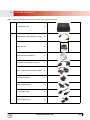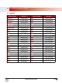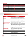
1
AV Connectivity, Distribution And Beyond...
VIDEO WALLS VIDEO PROCESSORS
VIDEO MATRIX SWITCHES
EXTENDERS SPLITTERS WIRELESS
CABLES & ACCESSORIES
12 Display Dual Image Video Wall Processor
Cascadable/Modular
Model #: DVI-VIDEOWALL-12X
© 2013 Avenview Inc. All rights reserved.
The contents of this document are provided in connection with Avenview Inc. (“Avenview”) products. Avenview makes no representations or
warranties with respect to the accuracy or completeness of the contents of this publication and reserves the right to make changes to specifications
and product descriptions at any time without notice. No license, whether express, implied, or otherwise, to any intellectual property rights is granted
by this publication. Except as set forth in Avenview Standard Terms and Conditions of Sale, Avenview assumes no liability whatsoever, and disclaims
any express or implied warranty, relating to its products of Avenview Inc. is strictly prohibited.
Product Application & Market Sectors
Corporate
House Of Worship
Military
Residential
Education
Industrial
Medical
Aviation
www.avenview.com
TABLE OF CONTENTS
1.
GETTING STARTED...........................................................................................................................1
1.1 Important Safeguards...............................................................................................................1
1.2 Safety Instructions...................................................................................................................1
1.3 Regulatory Notices Federal Communications Commission (FCC)............................ 2
2.Introduction...............................................................................................................................3
2.1Package Contents......................................................................................................................4
2.2 Before Installation....................................................................................................................5
2.3Panel Description........................................................................................................................5
2.3.1 DVI-VIDEOWALL-12X Front Panel............................................................................................5
2.3.2 DVI-VIDEOWALL-12X Rear Panel.............................................................................................5
2.3.3 Inputs and Outputs......................................................................................................................6
3.Installation...................................................................................................................................6
4.Panel Description........................................................................................................................8
5.
System Configuration...............................................................................................................8
6.
Software Operation...................................................................................................................9
7.State...................................................................................................................................................9
8.
Software Panel...........................................................................................................................10
9.
System Button............................................................................................................................10
10. Setup Individual Output Channel.....................................................................................11
11. 2x2 VIDEOWALL SETUP DVI OR HDMI.........................................................................................13
11.1 Hardware...................................................................................................................................13
11.2 Software.....................................................................................................................................13
12.CASCADING.....................................................................................................................................14
12. Supported Resolutions...........................................................................................................15
12.1 DVI-IN........................................................................................................................................15
12.2 DVI-OUT...................................................................................................................................16
13. General Troubleshooting....................................................................................................16
14.Specifications..............................................................................................................................17
www.avenview.com
Page
3
1.GETTING STARTED
SECTION 1: GETTING STARTED
1.1 Important Safeguards
Please read all of these instructions carefully before you use the device. Save this manual for future reference.
What the warranty does not cover
•• Any product, on which the serial number has been defaced, modified or removed.
•• Damage, deterioration or malfunction resulting from:
•• Accident, misuse, neglect, fire, water, lightning, or other acts of nature, unauthorized product modification, or failure to
follow instructions supplied with the product.
•• Repair or attempted repair by anyone not authorized by us.
•• Any damage of the product due to shipment.
•• Removal or installation of the product.
•• Causes external to the product, such as electric power fluctuation or failure.
•• Use of supplies or parts not meeting our specifications.
•• Normal wear and tear.
•• Any other causes which does not relate to a product defect.
•• Removal, installation, and set-up service charges.
1.2 Safety Instructions
The Avenview DVI-VIDEOWALL-12X Display Dual Image Video Wall Processor has been tested for conformity to safety
regulations and requirements, and has been certified for international use. However, like all electronic equipment’s, the DVIVIDEOWALL-12X should be used with care. Read the following safety instructions to protect yourself from possible injury and
to minimize the risk of damage to the unit.
! Do not dismantle the housing or modify the module.
! Dismantling the housing or modifying the module may result in electrical shock or burn.
! Refer all servicing to qualified service personnel.
! Do not attempt to service this product yourself as opening or removing housing may expose you to dangerous voltage
or other hazards
! Keep the module away from liquids.
! Spillage into the housing may result in fire, electrical shock, or equipment damage. If an object or liquid falls or spills on
to the housing, unplug the module immediately.
! Have the module checked by a qualified service engineer before using it again.
! Do not use liquid or aerosol cleaners to clean this unit. Always unplug the power to the device before cleaning.
www.avenview.com
Page
1
1.3 Regulatory Notices Federal Communications Commission (FCC)
This equipment has been tested and found to comply with Part 15 of the FCC rules. These limits are designed to provide
reasonable protection against harmful interference in a residential installation.
Any changes or modifications made to this equipment may void the user’s authority to operate this equipment.
Warning symbols
Description
ONLY USE THE PROVIDED POWER CABLE OR POWER
ADAPTER SUPPLIED. DO NOT TAMPER WITH THE
ELECTRICAL PARTS. THIS MAY RESULT IN ELECTRICAL
SHOCK OR BURN.
DO NOT TAMPER WITH THE UNIT. DOING SO WILL
VOID THE WARRANTY AND CONTINUED USE OF THE
PRODUCT.
THE VIDEO BOARDS ARE VERY SENSITIVE TO STATIC.
PLEASE ENSURE IF RACK MOUNTED OR INSTALLED ON A
SURFACE, IT SHOULD BE IN A GROUNDED ENVIROMENT.
www.avenview.com
Page
2
2.Introduction
Avenview DVI-VIDEOWALL-12X Dual image Videowall Processors has great Processing Power, for the most cost effective and
full real time data for multiple flat panel displays or projectors. DVI-VIDEOWALL-12X can support up to 12 DVI outputs to
expand the spectrum of video wall applications. This new concept of having Modular output cards and the ability to Cascade to
another unit.
Users can therefore adjust the number of output ports based on different scenarios.
The 4.95Gbps bandwidth of video, the controllability of the module, and the input complexity can be useful to either be cost
effective on project overheads or enhance the design with the new features from the new I/O cards. Designed with Thru DVI
transmission, the quality of the output video is guaranteed. With its user friendly software included any display layout can be
achieved. DVI-VIDEOWALL-12X allows you to manipulate two input videos, to any positions and whatever size you want for
viewing. The embedded Scaler converts signals from two of the input sources to match the native resolution of monitors, flat
panel displays, projectors as well as user-selectable output settings up to WUXGA (1920x1200). The DVI-VIDEOWALL-12X
sends the resulting mixed video thru DVI interface to the connected monitors/projectors based on the display layout. The
layout can be readily modified to fit your applications and optimize visual effects. Typical applications include digital signage, and
broadcasting/education/ surveillance systems etc.
-- PCIe interface add-on card design
-- Up to 12 DVI outputs from 640x480 to 1920x1200 with a local loop out for monitoring
-- Supports HDMI, DVI, S-Video, Composite, Component, and VGA input, from 640x480 to 1920x1200, interlaced or
progressive
-- Advanced video de-interlacer for improving 480i and 576i SD video input
-- PIP, PAB, Full screen modes and adjustable size & position through software
-- Resize, position, flip, zoom output video
-- Perfectly as a video screen splitter, a video converter and a video switcher
-- Each DVI output has an independent controllable display area
-- User-selectable output settings, up to 1920x1200
-- Can be cascaded to obtain more displays
-- Image parameters and layouts are automatically saved in flash memory of the device and can be recalled for later use
-- Several Image parameters and layouts can be saved in computers and can be loaded for later use
-- Software control through RS-232 / RS-485
-- Built-in long distance RS-232 control port over Cat-5e
-- Firmware upgradable for support of new features and technology enhancements
-- Built-in factory reset switch
-- 2.5RU size
-- Optional Ethernet control card support
www.avenview.com
Page
3
2.1Package Contents
Before you start the installation of the converter, please check the package contents.
1
DVI-VIDEOWALL-12X
X1
COMPOSITE & S-VIDEO BREAKOUT CABLE
X1
USER’S MANUAL
X1
INSTALLATION SOFTWARE CD
X1
DVI TO DVI & VGA BREAKOUT CABLE
X1
VGA TO COMPONENT BREAKOUT CABLE
X1
DVI TO VGA ADAPTER
X1
RS232 TO USB ADAPTER
X1
UL AC POWER CORD
X1
RACK-MOUNTING KIT
X2
2
www.avenview.com
Page
4
2.2 Before Installation
•• Put the product in an even and stable location. If the product falls down or drops, it may cause an injury or malfunction.
•• Don’t place the product in too high temperature (over 50°C), too low temperature (under 0°C) or high humidity.
•• Use the DC power adapter with correct specifications. If inappropriate power supply is used then it may cause a fire.
•• Do not twist or pull by force ends of the optical cable. It can cause malfunction.
2.3Panel Description
1
2.3.1 DVI-VIDEOWALL-12X Front Panel
1. LED: Shows current configuration
2.3.2 DVI-VIDEOWALL-12X Rear Panel
2
3 4 5
6
78 9
9 10
11
2. AC Power:100-240V
3. Video Input: S-Video/Comosite Input
4. Power switch: ON/OFF
5. Video Input: DVI/HDMI VGA video foramt
6. RS-232: Device Control communication port Via
RS-232 Cable or USB to RS-232 (Supplied)
7. Dip Switch: UP Position - Normal operationmode;
Down Position - Firmware update mode
8. Device ID: To identify multiple units in cascademode
9. RS-485: Communication ports for cascade mode
10. Dip Switch: UP- Factory Default and RS-232 control
Mode. DOWN- RS485 mode (Cascade Function)
11. Output Ports: DVI/HDMI compatible 12 outputports to display/monitor
www.avenview.com
Page
5
2.3.3 Inputs and Outputs
The Avenview DVI-VIDEOWALL-12X can accept inputs from HDMI, DVI, CVBS, YPbPr, VGA and accepts both graphics
and video signals, which come from computers and NTSC/PAL video sources respectively. There is a concept of main
channel and sub channel for this device. You can pick up one of the digital inputs and one of the analog inputs, and then DVIVIDEOWALL-12X will display the mixed video on the connected 12 displays. With an advanced de-interlace built in, low
resolution but popular video formats such as NTSC/PAL will be improved.
“Firmware updating: The up state of DIP switchers is normal operation mode; down state is firmware update
mode.
“Default: Turn on the DVI-VIDEOWALL-12X then switch Pin 1 of DIP switcher simultaneously “up” and “down”
to factory default mode. Pin 2 of DIP switcher “up” is RS232 mode; “down” is RS-485 mode.
“These ten ports (including DVI Local Output) support various resolutions from 640x480 up to 1920x1200, for
more detail of the supported modes; please refer to the Appendix – Supported Resolution.
3.Installation
To setup Avenview DVI-VIDEOWALL-12X follow the steps outlined below for connecting to a device.
1. Use the best quality DVI, DVI-HDMI, VGA, Composite, S-Video cables.
2. Turn OFF DVI-VIDEOWALL-12X and all devices that are to be connected to it.
3. Connect 12 Monitors (or projectors, TV or other display devices) to DVI OUTPUT of DVI-VIDEOWALL-12X.
4. Connect the Source device (such as, PC, DVD Player, or Media Player etc.) to DVI-VIDEOWALL-12X.
5. Connect a Windows based laptop or desktop (that will used to configure the DVI-VIDEOWALL-12X) to DVIVIDEOWALL-12X by RS-232 to USB Adapter.
6. Power ON DVI-VIDEOWALL-12X.
7. Turn ON all devices connected to DVI-VIDEOWALL-12X and then setup the DVI-VIDEOWALL-12X from the system
through RS-232 to USB Adapter and provided Avenview software.
www.avenview.com
Page
6
-- DO NOT block the sides of this device or stack another device on the top or bottom of the DVI-VIDEOWALL12X. If sides of the units are blocked it will block the air flow from the fans on the side of the unit. This could
cause system to over-heat, which may result in system failure.
www.avenview.com
Page
7
4.Panel Description
The Avenview DVI-VIDEOWALL-12X includes Software Control program which runs under Windows XP or later.
Connect the provide RS-232 to USB adapter to DVI-VIDEOWALL-12X and USB Port to your Windows based system that will
be used to configure the DVI-VIDEOWALL-12X. Once it is connected to USB Port, Windows will look for appropriate drivers.
If you are using an older version of Windows, then insert the Installation CD (provided) and have Windows search for drivers
(you may need to download latest drivers from Prolific’s website if you are using Windows Vista or Windows7/8).
5.
System Configuration
1. Power up the DVI-VIDEOWALL-12X and you can see Vacuum Fluorescent Dislay (VFD) on the front panel blinks. Make
sure the serial port (RS232) connection is secured.
2. When Avenview software is launched, let it automatically detect the device response from RS-232 port. The process
takes 5 – 15 seconds. If there is no response, a warning window will show up.
The possible reasons causing above error could be:
-- No Power to DVI-VIDEOWALL-12X or it is in sleep state. If this is the case then check the power and restart
theDVI-VIDEOWALL-12X
-- The serial connection is not well established. Please ensure that drivers are properly installed and all cables are
securely connected. Check device manager, and ensure that RS-232 to USB Adapter is assigned COM Port #
and there is no exclamation mark.
www.avenview.com
Page
8
6.
Software Operation
7.State
Overall State and Format Settings:
1. Save and Read: The current layout of the twelve outputs can be saved
to a file. The file can be uploaded in the future to resume the settings.
2. Display Setting: The main and sub sources, both can be adjusted to
16:12 or 4:3 aspect ratio. The brightness and contrast of the mixed
video also can be adjusted for different requirement. After adjusting
the settings, press Update Setting to save the changes.
3. Firmware Ver.: Display the current firmware of the device.
4. Color Balance: The color of the video can be automatically adjusted.
It only works when the source is Analog and the mode is Full Screen.
www.avenview.com
Page
9
8.
Software Panel
Button Name
Description & Function
State
Please refer to Section 1.12
Setting
Serial Port Setting –Select the correct COM Port for Connection to device.
Connect
Once the correct COM port selected this button activates connection to device
Disconnect
Disconnects communication to the RS232 port
System
Please refer to section 1.14 (System Control)
Input Resolution
Set the Input Resolution of the source 800x600@60Hz to 1920X1200@60Hz
Main Source
Choose which source will be the MAIN from CVBS\SVIDEO\VGA\DVI HDMI
Sub Source
Choose which source will be the SUB from CVBS\SVIDEO\VGA\DVI HDMI
Display Layout
Mode
Choose your OUTPUT Layout Main Full Screen\Sub Full\PIP Mode\Side By side\
Custom
9.
System Button
This tab has been made available because of the new DVI Modular PCB card design. This allows the user to add /remove
Modular cards to the unit up to 12 Output cards, and configure and update their status individually;
Input State: ON/OFF
Power State: ON/OFFUniversal Power Ports ON/OFF
Firmware Update: 1-12 Output cards Get System Information
www.avenview.com
Page
10
10. Setup Individual Output Channel
There are totally 12 channel outputs for DVI-VIDEOWALL-12X, and each output can be independently setup to display any
area of the input video. Each output can be with different output resolutions to adapt different combinations of monitors or
projectors.
To select each individual Output to setup with preferable output, please
click on the desired Output, and the control dialog windows will show
up accordingly.
4
1
2
5
2
3
5
www.avenview.com
Page
11
For each display, users can define which area of the input video is to be displayed. Fundamentally, setup the X Total and Y Total
first, and then define the upper-left (X Start, Y Start) and bottom-right (X End, Y End) corners for each display channel. The
control panel to achieve this goal is as shown.
1
This area demonstrates the corresponding Video Selection and Monitor of the Input video to be display for
the selected Output Channel.
“Original Input Video” shows the resolution information of the Input Video to each Output Channel.
This also varies depending on the Input Video
2
“Selected Area” shows the information of the selected area to be displayed. The numbers will vary
according to different settings.
“Output Resolution”: In this section, you can setup the output resolution for individual Output Channel.
Notice that each display can output at different resolutions depending on supported resolution of the
connected monitor/TV to that output channel.
3
“Capture Mode Enable” will enable parameters effective. If users disabled this selection, each
output channel will display simply the full display of the input source.
“Auto Apply Settings” will automatically load the new settings into processor.
Clicking on “Update Status” will keep the information of Input video updated
Clicking on “Update Apply Settings” will load the parameters into the video processor.
4
5
Define X Total, Y Total, Upper-Left X, Y point coordinates using scroll bars or manually keying in this
section. This section will roughly define these quantities which are needed for each Output channel. The
resulting capture area corresponds to the Input video is illustrated in Window to left.
“Fine Tune by Percentage” provides the alternative to further adjust the position and area defined in
section 4.
For Outward Extension
For Inward Shrink
By percentage, users need to determine what will be the reference. There are two choices for this part
“Specified Area” and “Full Input”. Normally, “Specified Area” will work more appropriately while
users are dealing with panel masking, because the overlapped masking area will be closed to specified area
instead of full input video.
6
“Fine Tune by Pixel” offers similar approach to adjust the position and area of the Output channel. The
idea behind this section is the same to “Fine Tune by Percentage”. The difference is that the adjustment
is based on Pixel. Users can therefore adjust the Output Channel area based on Pixels.
www.avenview.com
Page
12
11. 2x2 VIDEOWALL SETUP DVI OR HDMI
11.1 Hardware
Please connect DVI or DVI/HDMI cable Output 1 to Monitor 1
Please connect DVI or DVI/HDMI cable Output 2 to Monitor 2
1
2
3
4
Please connect DVI or DVI/HDMI cable Output 3 to Monitor 3
Please connect DVI or DVI/HDMI cable Output 4 to Monitor 4
11.2 Software
1. Click on Display Output 1
2. In display area setting set the X Total: 2 / Y Total: 2 for 2x2 Setup
1
2
Note: Display Area
Setting Values
3
4
www.avenview.com
Page
13
12.CASCADING
The Avenview DVI-VIDEOWALL-12X can be cascaded with as many as 255 DVI-VIDEOWALL-12X devices.
Rotary Dial - This allows
the user to set the ID of
the UNITS
Control Software - This
allows the user to configure
and change settings to
finalize the output results
www.avenview.com
Page
14
12. Supported Resolutions
12.1 DVI-IN
Supported Mode
Resolution
Supported Mode
Resolution
480P/525P
720x483 @60Hz
MAC
832x624 @75Hz
480P (16:12)
1260x483 @60Hz
VESA
1024x768 @60Hz
576P/625P
720x756 @50Hz
MAC
1024x768 @60Hz
(HDTV) 720p
1280x720 @50Hz
VESA
1024x768 @70Hz
(HDTV) 720p
1280x720 @60Hz
IBM
1024x768 @72Hz
(HDTV) 1080p
11220x1080 @30Hz
VESA
1024x768 @75Hz
VESA
720x400 @85Hz
MAC
1024x768 @75Hz
VESA
640x350 @85Hz
VESA
1024x768 @85Hz
VESA
640x400 @85Hz
VESA
1152x864 @75Hz
IBM
720x400 @70Hz
MAC
1152x870 @75Hz
IBM
720x350 @70Hz
SUN
1152x1200 @66Hz
IBM
640x350 @70Hz
SUN
1152x1200 @76Hz
IBM
640x400 @70Hz
VESA
1280x1260 @60Hz
VESA
640x480 @60Hz
VESA
1280x1260 @85Hz
MAC
640x480 @67Hz
VESA
1280x1024 @60Hz
VESA
640x480 @72Hz
HP
1280x1024 @60Hz
VESA
640x480 @75Hz
IBM
1280x1024 @67Hz
VESA
640x480 @85Hz
HP
1280x1024 @72Hz
VESA
800x600 @56Hz
VESA
1280x1024 @75Hz
VESA
800x600 @60Hz
SUN
1280x1024 @76Hz
VESA
800x600 @72Hz
VESA
1600x1200 @60Hz
VESA
800x600 @75Hz
VESA
11220x1200 @60Hz
VESA
800x600 @85Hz
www.avenview.com
Page
15
12.2 DVI-OUT
Supported Mode
(HDTV) 720p
Resolution
1280x720 @50Hz
Supported Mode
VESA
Resolution
1280x768 @60Hz
(HDTV) 720p
1280x720 @60Hz
VESA
1366x768 @60Hz
(HDTV) 1080p
11220x1080 @60Hz
VESA
1400x1050 @60Hz
VESA
640x480 @60Hz
VESA
1400x1050 @50Hz
VESA
800x600 @60Hz
VESA
1152x864 @75Hz
VESA
1024x768 @60Hz
VESA
1600x1200 @60Hz
VESA
1152x864 @75Hz
VESA
11220x1200 @50Hz
VESA
1280x1024 @60Hz
VESA
11220x1200 @60Hz
VESA
1280x1024 @50Hz
13. General Troubleshooting
Problem
Possible Solution
1. Check if AC Power Cord is firmly plugged into DVI-VIDEOWALL-12X
No Power
2. If you are recovering from Power Outage, leave the device OFF for a
while and then power it ON again.
3. Make sure all cables are in good working condition and properly connected
DVI-VIDEOWALL-12X.
Off-Center Screen Image,
Odd Colors or No Picture
4. Configure the Output video resolution so that it doesn’t exceed the
native supported resolution of TV/Monitor/Projector (Display). Usually a
message of “Out of Range” is display on TV/Monitor.
5. Every time you change the resolution of Input Source, wait 10 – 20
seconds. After the resolution is changed, the selection of Input and the
Display layout mode will return to default. Adjust the Input source and
Display Layout Mode to your requirements again.
6. VGA Source can take up to 10 Seconds before it is recognized
Poor Quality Video
7. We suggest you don’t use T-Connectors to split your video source into
images displayed on two difference screens. This lowers the Output video
quality. Use a distribution amplifier instead of T-Connectors
8. Make sure the video source is not compressed and maintains the highest
native resolution
Wrong Color
9. Press “Color Balance” key in “State” for auto configuration.
Poor Linking
10.When the linking of the Serial Control cannot work, reboot DVIVIDEOWALL-12X to establish the link.
www.avenview.com
Page
16
14.Specifications
Item
Model
Unit Description
Video Format Support
Dual Output Support
Description
DVI-VIDEOWALL-12X
12 Display Video Wall Processor
HDMI, DVI, VGA, Component, S-Video, Composite
(Only one Digital and one Analog can be input simultaneously)
DVI & VGA
Local Output
Video Bandwidth
Supported Resolutions
Yes
DVI (Single Link 4.125Gbps)
VGA (165MHz)
Up to 1920x1200@60Hz
Audio Support
System Control
No
RS-232 / RS-485
Cascadable
Input TMDS Signal
Input DDC Signal
ESD Protection
Yes
1.2 Volts (peak-to-peak)
5 Volts (peak-to-peak, TTL)
- Human body model — ±15kV (air-gap discharge) & ±8kV
(contact discharge)
- Core chipset — ±8kV
DVI x 1
S-Video x 1
Input Connectors
RS232 x 1
RS485 x 1
Output Connectors
HDMI Input Selection
DVI x 12
Push Button / IR Remote / RS232
Push Button / IR Remote
RCA Connector
75Ω female
DVI Connector
DVI-I (212-pin female, digital only)
RJ45 Connector
WE/SS 8P8C with 2 LED indicators
RS232 Connector
DE-12 (12-pin D-sub Female)
Dimensions (L x W x H)
Unit- 17.75” x 17.25” x 3.5”
Dimensions (L x W x H)
Package-23” x 20” x 9.5”
Power Supply
Power Consumption
AC Power 100~240V
60 Watt (max)
Environmental
Operating Temperature
Storage Temperature
Relative Humidity
32˚ ~ 104˚F (0˚ to 40˚C)
-4˚ ~ 140˚F (-20˚ ~ 60˚C)
20~120% RH (no condensation)
www.avenview.com
Page
17
Notice
1. If the DVI or HDMI device requires the EDID information, please use EDID Reader/Writer to
retrieve and provide DVI/HDMI EDID information.
2. All HDMI over CAT5 transmission distances are measured using Belden 1583A CAT5e 125MHz
LAN cable and ASTRODESIGN Video Signal Generator VG-8512C.3
3. The transmission length is largely affected by the type of LAN cables, the type of HDMI sources,
and the type of HDMI display. The testing result shows solid LAN cables (usually in bulk cable
300m or 1000ft form) can transmit a lot longer signals than stranded LAN cables (usually
in patch cord form). Shielded STP cables are better suit than unshielded UTP cables. A solid
UTP CAT5e cable shows longer transmission length than stranded STP CAT6 cable. For long
extension users, solid LAN cables are your only choice.
4. EIA/TIA-568-B termination (T568B) for LAN cables is recommended for better performance.
5. To reduce the interference among the unshielded twisted pairs of wires in LAN cable, you can
use shielded LAN cables to improve EMI problems, which is worsen in long transmission.
6. Because the quality of the LAN cables has the major effects in how long transmission distance will
be made and how good is the received display, the actual transmission length is subject to your
LAN cables. For resolution greater than 1080i or 1280x1024, a CAT6 cable is recommended.
7. If your HDMI display has multiple HDMI inputs, it is found that the first HDMI input [HDMI
input #1] generally can produce better transmission performance among all HDMI inputs.
www.avenview.com
Page
18
Notes
www.avenview.com
Page
19
Avenview Warranty Certificate
AVENVIEW CORP. (“Avenview”) warrants Avenview-branded product(s) contained in the original packaging against defects in materials and workmanship when used
normally in accordance with Avenview's enclosed manual guidelines for a period of THREE (3) YEARS from the date of original retail purchase - Warranty Period. Avenview’s
published guidelines include but are not limited to information contained in technical specifications, user manuals and service communications.
LABOR: During the Warranty Period of THREE (3) YEARS, Avenview will repair or replace the product(s) at no cost using new or used parts equivalent to novel performance
and reliability if the product(s) is determined to have abide by Avenview’s published guidelines. Cost of Labor applicable to product(s) after Warranty Period. For labor costs,
please contact [email protected].
PARTS: During the Warranty Period of of THREE (3) YEARS, Avenview will supply new or rebuilt replacements in exchange for defective parts of the product(s) at no cost if
the product(s) is determined to have abide by Avenview’s published guidelines. Cost of Parts applicable to product(s) after Warranty Period. For part(s) costs, please contact
[email protected].
To obtain Warranty: (a) proof of purchase in the form of a bill of sale or receipted invoice reflecting that the registered product(s) is within warranty period must be presented
to obtain warranty service; (b) product(s) must be registered at time of purchase. Failure to do so will result in applicable parts and labor charges. Returning product(s) must
be shipped in Avenview’s original packaging or in packaging pertaining equal degree of protection to Avenview’s. Both Avenview and purchaser are responsible for freight
charges and brokerages when shipping the product(s) to the receiver.
NOT COVERED BY THIS WARRANTY
This warranty does not apply to any non-Avenview branded product(s); non-registered Avenview product(s). This warranty does not apply: (a) to cosmetic damage, including
but not limited to scratches, dents and broken cords; (b) to damage caused by use with another product; (c) to damage caused by accident, abuse, misuse, liquid contact, fire,
earthquake or other external cause; (d) to damage caused by operating the Avenview product(s) outside Avenview’s manuals or guidelines; (e) to damage caused by service
performed by anyone who is not a representative of Avenview or an Avenview authorized personnel; (f) to defects caused by normal wear and tear or otherwise due to the
normal aging of the Avenview product(s), or (g) if any serial number has been removed or defaced from the Avenview product(s).
AVENVIEW IS NOT LIABLE FOR DIRECT, SPECIAL, INCIDENTAL OR CONSEQUENTIAL DAMAGES RESULTING FROM ANY BREACH OF WARRANTY OR
CONDITION, OR UNDER ANY OTHER LEGAL THEORY, INCLUDING BUT NOT LIMITED TO LOSS OF USE; LOSS OF REVENUE; LOSS OF ACTUAL OR
ANTICIPATED PROFITS (INCLUDING LOSS OF PROFITS ON CONTRACTS); LOSS OF THE USE OF MONEY; LOSS OF ANTICIPATED SAVINGS; LOSS OF BUSINESS;
LOSS OF OPPORTUNITY; LOSS OF GOODWILL; LOSS OF REPUTATION; LOSS OF, DAMAGE TO, COMPROMISE OR CORRUPTION OF DATA; OR ANY INDIRECT
OR CONSEQUENTIAL LOSS OR DAMAGE REPAIR OR REPLACEMENT AS PROVIDED UNDER THIS WARRANTY IS THE EXCLUSIVE REMEDY OF THE CONSUMER.
Some states do not allow the inclusion or limitation of incidental or consequential damages, or allow limitations on duration implements of the Warranty Period; therefore the above limitations or
exclusions may not be applicable to you. This warranty gives you specific legal rights, and you may have other rights which vary from state to state.
275 Woodward Avenue, Kenmore, NY 14217
1.866.508.0269
www.avenview.com
AV Connectivity, Distribution And Beyond...
TECHNICAL SUPPORT
Disclaimer
While every precaution has been taken in the preparation of this document, Avenview Inc. assumes no liability with respect to the operation or use of
Avenview hardware, software or other products and documentation described herein, for any act or omission of Avenview concerning such products or this
documentation, for any interruption of service, loss or interruption of business, loss of anticipatory profits, or for punitive, incidental or consequential damages
in connection with the furnishing, performance, or use of the Avenview hardware, software, or other products and documentation provided herein.
Avenview Inc. reserves the right to make changes without further notice to a product or system described herein to improve reliability, function or design.
With respect to Avenview products which this document relates, Avenview disclaims all express or implied warranties regarding such products, including but
not limited to, the implied warranties of merchantability, fitness for a particular purpose, and non-infringement.