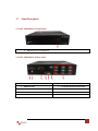
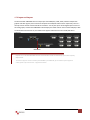
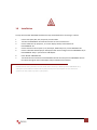
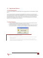
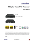
1
9 Display Video Wall Processor Model #: DVI-VIDEOWALL-9X © 2010 Avenview Inc. All rights reserved. The contents of this document are provided in connection with Avenview Inc. (“Avenview”) products. Avenview makes no representations or warranties with respect to the accuracy or completeness of the contents of this publication and reserves the right to make changes to specifications and product descriptions at any time without notice. No license, whether express, implied, or otherwise, to any intellectual property rights is granted by this publication. Except as set forth in Avenview Standard Terms and Conditions of Sale, Avenview assumes no liability whatsoever, and disclaims any express or implied warranty, relating to its products including, but not limited to, the implied warranty of merchantability, fitness for a particular purpose, or infringement of any intellectual property right. Reproduction of this manual, or parts thereof, in any form, without the express written permission of Avenview Inc. is strictly prohibited. www.avenview.com 1 Table of Contents Section 1: Getting Started ...................................................................................................................... 4 1.1 Important Safeguards ............................................................................................................ 4 1.2 Safety Instructions ................................................................................................................. 4 1.3 Regulatory Notices Federal Communications Commission (FCC) ......................................... 5 1.4 Introduction ........................................................................................................................... 5 1.5 Package Contents................................................................................................................... 8 1.6 Before Installation.................................................................................................................. 8 1.7 Panel Description ................................................................................................................... 9 1.7.1 DVI-VIDEOWALL-9X Front Panel ........................................................................................... 9 1.7.2 DVI-VIDEOWALL-9X Rear Panel ............................................................................................. 9 1.7.3 Inputs and Outputs ............................................................................................................. 10 1.8 Installation ........................................................................................................................... 11 1.9 Operation and Software ...................................................................................................... 12 1.9.1 System Requirements ......................................................................................................... 12 1.9.2 System Connection.............................................................................................................. 12 1.9.3 Software Operation ............................................................................................................. 13 1.9.3.1 State ................................................................................................................................. 13 1.9.3.2 Settings ............................................................................................................................. 14 1.9.3.3 Connect ............................................................................................................................ 14 1.9.3.4 Disconnect ........................................................................................................................ 14 1.9.3.5 Input Resolution ............................................................................................................... 14 1.9.3.6 Main Source ..................................................................................................................... 14 1.9.3.7 Sub Source ........................................................................................................................ 14 1.9.3.8 Display Layout Mode ........................................................................................................ 14 1.9.4 Setup Individual Output Channel ........................................................................................ 15 1.9.5 CASCADING ......................................................................................................................... 17 1.10 Supported Resolutions......................................................................................................... 18 www.avenview.com 2 1.10.1 DVI-IN ................................................................................................................................ 18 1.10.2 DVI-OUT............................................................................................................................. 18 1.11 General Troubleshooting ..................................................................................................... 19 Section 2: Specifications....................................................................................................................... 20 www.avenview.com 3 Section 1: Getting Started 1.1 Important Safeguards Please read all of these instructions carefully before you use the device. Save this manual for future reference. What the warranty does not cover Any product, on which the serial number has been defaced, modified or removed. Damage, deterioration or malfunction resulting from: Accident, misuse, neglect, fire, water, lightning, or other acts of nature, unauthorized product modification, or failure to follow instructions supplied with the product. Repair or attempted repair by anyone not authorized by us. Any damage of the product due to shipment. Removal or installation of the product. Causes external to the product, such as electric power fluctuation or failure. Use of supplies or parts not meeting our specifications. Normal wear and tear. Any other causes which does not relate to a product defect. Removal, installation, and set-up service charges. 1.2 Safety Instructions The Avenview DVI-VIDEOWALL-9X. 9-Display Video Wall Processor has been tested for conformity to safety regulations and requirements, and has been certified for international use. However, like all electronic equipment’s, the DVI-VIDEOWALL-9X should be used with care. Read the following safety instructions to protect yourself from possible injury and to minimize the risk of damage to the unit. Do not dismantle the housing or modify the module. Dismantling the housing or modifying the module may result in electrical shock or burn. Refer all servicing to qualified service personnel. Do not attempt to service this product yourself as opening or removing housing may expose you to dangerous voltage or other hazards Keep the module away from liquids. Spillage into the housing may result in fire, electrical shock, or equipment damage. If an object or liquid falls or spills on to the housing, unplug the module immediately. Have the module checked by a qualified service engineer before using it again. Do not use liquid or aerosol cleaners to clean this unit. Always unplug the power to the device before cleaning. www.avenview.com 4 1.3 Regulatory Notices Federal Communications Commission (FCC) This equipment has been tested and found to comply with Part 15 of the FCC rules. These limits are designed to provide reasonable protection against harmful interference in a residential installation. Any changes or modifications made to this equipment may void the user’s authority to operate this equipment. 1.4 Introduction The Avenview DVI-VIDEOWALL-9X, 9-Display Video Wall Processor is a powerful, most cost effective, and fully real time data/video processor for multiple flat panel displays or projectors. Thru DVI transmission, the quality of the outcome videos is guaranteed. The output display is grained up to 255 by 255 squares. Virtually any setups for the display layout can be possible by the provided software. The DVI-VIDEOWALL-9X allows you to manipulate two input videos, wherever positions and whatever sizes you want for viewing. The embedded scalar converts signals from two of the input sources to match the native resolution of monitors, flat panel displays, projectors as well as user-selectable output settings up to WUXGA (1920x1200). The DVI-VIDEOWALL-9X sends the resulting mixed video thru DVI interface to the connected monitors/projectors based on the display layout. The layout can be readily modified to fit your applications and optimize visual effects. Typical applications include digital signage, and broadcasting/education/surveillance systems etc. - Nine DVI outputs from 640x480 to 1920x1200 with a local loop out for monitoring Supports HDMI, DVI, S-Video, CVBS, Component, and VGA input, from 640x480 to 1920x1200, interlaced or progressive Advanced video de-interlace for improving 480i and 576i SD video input PIP, PAB, Full screen modes and adjustable size& position through software Resize, position, flip, zoom output video Perfectly as a video screen splitter, a video converter and a video switcher Each DVI output has an independent controllable display area User-selectable output settings, up to 1920x1200 Can be cascaded to obtain more displays Image parameters and layouts are automatically saved in flash memory of the device and can be recalled for later use Several Image parameters and layouts can be saved in computers and can be loaded for later use Software control through RS-232/RS-485 Built-in long distance RS-232 control port over Cat-5e Firmware upgradable for support of new features and technology enhancements Built-in factory reset switch 2U size www.avenview.com 5 www.avenview.com 6 www.avenview.com 7 1.5 Package Contents Before you start the installation of the converter, please check the package contents. - DVI-VIDEOWALL-9X RS232 to USB Adapter Rack-mounting Kit UL AC Power Cord Installation Software CD DVI to VGA Adapter Component to VGA Adapter DVI to DVI & VGA breakout cable Composite & S-Video breakout cable x1 x1 x2 x1 x1 x1 x1 x1 x1 - User’s Manual x1 1.6 Before Installation Put the product in an even and stable location. If the product falls down or drops, it may cause an injury or malfunction. Don’t place the product in too high temperature (over 50°C), too low temperature (under 0°C) or high humidity. Use the DC power adapter with correct specifications. If inappropriate power supply is used then it may cause a fire. Do not twist or pull by force ends of the optical cable. It can cause malfunction. www.avenview.com 8 1.7 Panel Description 1.7.1 DVI-VIDEOWALL-9X Front Panel 1 1. LED: Shows current configuration 1.7.2 DVI-VIDEOWALL-9X Rear Panel 1 2 3 4 5 6 7 1. AC Power 2. RS232 Connector 3. RS485 Connector 4. S-Video/Composite Input Connector 5. DVI Input Connector 6. DVI Local Output Connector 7. DVI Output Connectors 1 – 9 www.avenview.com 9 1.7.3 Inputs and Outputs The Avenview DVI-VIDEOWALL-9X can accept inputs from HDMI, DVI, CVBS, YPbPr, VGA and accepts both graphics and video signals, which come from computers and NTSC/PAL video sources respectively. There is a concept of main channel and sub channel for this device. You can pick up one of the digital inputs and one of the analog inputs, and then DVI-VIDEOWALL-9X will display the mixed video on the connected 9 displays. With an advanced de-interlace built in, low resolution but popular video formats such as NTSC/PAL will be improved. DIP Switch Default: Turn on the DVI-VIDEOWALL-9X then switch both DIP switches simultaneously up and down to factory default mode. The IO Ports supports various resolution from 640x480 up to 1920x1200, for more details of the supported modes, please refer to the Section – Supported resolution www.avenview.com 10 1.8 Installation To setup Avenview DVI-VIDEOWALL-9X follow the steps outlined below for connecting to a device. 1. 2. 3. 4. 5. 6. 7. Use the best quality DVI, VGA, Composite, S-Video cables. Turn OFF DVI-VIDEOWALL-9X and all devices that are to be connected to it. Connect 9 Monitors (or projectors, TV or other display devices) to DVI OUTPUT of DVI-VIDEOWALL-9X. Connect the Source device (such as, PC, DVD Player, Media Player etc.) to DVI-VIDEOWALL-9X. Connect a Windows based laptop or desktop (that will used to configure the DVI-VIDEOWALL-9X) to DVI-VIDEOWALL-9X by a –pm RS-232 to USB Adapter. Power ON DVI-VIDEOWALL-9X. Turn ON all devices connected to DVI-VIDEOWALL-9X and then setup the DVI-VIDEOWALL-9X from the system through RS-232 to USB Adapter and provided Avenview software. DO NOT block the sides of this device or stack another device on the top or bottom of the DVI-VIDEOWALL-9X. If sides of the units are blocked it will block the air flow from the fans on the side of the unit. This could cause system to over-heat, which may result in system failure. www.avenview.com 11 1.9 Operation and Software 1.9.1 System Requirements The Avenview DVI-VIDEOWALL-9X includes Software Control program which runs under Windows XP / 2000 / Vista / 7. Connect the provide RS-232 to USB adapter to DVI-VIDEOWALL-9X and USB Port to your Windows based system that will be used to configure the DVI-VIDEOWALL-9X. Once it is connected to USB Port, Windows will look for appropriate drivers. If you are using an older version of Windows, then insert the Installation CD (provided) and have Windows search for drivers (you may need to download latest drivers from Prolific’s website if you are using Windows Vista or Windows 7). 1.9.2 System Connection 1. 2. Power up the DVI-VIDEOWALL-9X and you can see Vacuum Fluorescent Dislay (VFD) on the front panel blinks. Make sure the serial port (RS232) connection is secured. When Avenview software is launched, let it automatically detect the device response from RS-232 port. The process takes 5 – 15 seconds. If there is no response, a warning window will show up. The possible reasons causing above error could be: - No Power to DVI-VIDEOWALL-9X or it is in sleep state. If this is the case then check the power and restart theDVI-VIDEOWALL-9X The serial connection is not well established. Please ensure that drivers are properly installed and all cables are securely connected. Check device manager, and ensure that RS-232 to USB Adapter is assigned a COM Port # and there is no exclamation mark. www.avenview.com 12 1.9.3 Software Operation 1.9.3.1 State Overall State and Format Settings: 1. 2. 3. 4. Save and Read: The current layout of the nine outputs can be saved to a file. The file can be uploaded in the future to resume the settings. Display Setting: The main and sub sources, both can be adjusted to 16:9 or 4:3 aspect ratio. The brightness and contrast of the mixed video also can be adjusted for different requirement. After adjusting the settings, press Update Setting to save the changes. Firmware Ver.: Display the current firmware of the device. Color Balance: The color of the video can be automatically adjusted. It only works when the source is Analog and the mode is Full Screen. www.avenview.com 13 1.9.3.2 Settings Setting for correct COM Port for Serial Control and the Device number for identification. 1.9.3.3 Connect Makes connection to attached device via RS232 to USB Adapter. 1.9.3.4 Disconnect Disconnects the attached device. 1.9.3.5 Input Resolution Here you can set the resolution of Input. It can take up to 10 seconds for new resolution to take effect. 1.9.3.6 Main Source Choose one of the Input sources from DVI, VGA, CVBS or S-Video 1.9.3.7 Sub Source Choose one of the Input sources from DVI, VGA, CVBS or S-Video 1.9.3.8 Display Layout Mode Setting the layout of the main and sub sources in mixed video. 1. 2. 3. 4. 5. Main Full Screen: Only main source is displayed in the mixed video Sub Full Screen: Only sub source is displayed in the mixed video PIP Mode: The main source is displayed as the background, and the sub source is shown has Picture-in-Picture. Side by Side: The two input sources are displayed side by side Custom Define PAP: User can adjust the layout of the two input sources without any limitations. Main and Sub sources can be from the same Input. www.avenview.com 14 1.9.4 Setup Individual Output Channel There are totally 9 channel outputs for DVI-VIDEOWALL-9X, and each output can be independently setup to display any area of the input video. Each output can be with different output resolutions to adapt different combinations of monitors or projectors. To select each individual Output to setup with preferable output, please click on the desired Output, and the control dialog windows will show up accordingly. 4 1 2 5 6 3 www.avenview.com 15 For each display, users can define which area of the input video is to be displayed. Fundamentally, setup the X Total and Y Total first, and then define the upper-left (X Start, Y Start) and bottom-right (X End, Y End) corners for each display channel. The control panel to achieve this goal is as shown. 1 2 3 4 This area demonstrates the resulting selection of the Input video to be display for the selected Output Channel. “Original Input Video” shows the resolution information of the Input Video to each Output Channel. It varies up the Input Video “Selected Area” shows the information of the selected area to be displayed. The numbers will vary according to different settings. “Output Resolution”: In this section, you can setup the output resolution for individual Output Channel. Notice that each display can output at different resolutions depending on supported resolution of the connected monitor/TV to that output channel. “Capture Mode Enable” will enable parameters effective. If users disabled this selection, each output channel will display simply the full display of the input source. “Auto Apply Settings” will automatically load the new settings into processor. Clicking on “Update Status” will keep the information of Input video updated Clicking on “Update Apply Settings” will load the parameters into the video processor. Define X Total, Y Total, Upper-Left X, Y point coordinates using scroll bars or manually keying in this section. This section will roughly define these quantities which are needed for each Output channel. The resulting capture area corresponds to the Input video is illustrated in Window to left. “Fine Tune by Percentage” provides the alternative to further adjust the position and area defined in section 4. 5 6 For Outward Extension For Inward Shrink By percentage, users need to determine what will be the reference. There are two choices for this part “Specified Area” and “Full Input”. Normally, “Specified Area” will work more appropriately while users are dealing with panel masking, because the overlapped masking area will be closed to specified area instead of full input video. “Fine Tune by Pixel” offers similar approach to adjust the position and area of the Output channel. The idea behind this section is the same to “Fine Tune by Percentage”. The difference is that the adjustment is based on Pixel. Users can therefore adjust the Output Channel area based on Pixels. www.avenview.com 16 1.9.5 CASCADING The Avenview DVI-VIDEOWALL-9X can be cascaded with as many as 255 DVI-VIDEOWALL-9X devices. To cascade two DVI-VIDEOWALL-9X, connect a DVI cable from Local Output of Unit 1 to DVI Input of Unit 2. www.avenview.com 17 1.10 Supported Resolutions 1.10.1 DVI-IN Supported Mode Resolution Supported Mode Resolution 480P/525P 720x483 @60Hz MAC 832x624 @75Hz 480P (16:9) 960x483 @60Hz VESA 1024x768 @60Hz 576P/625P 720x756 @50Hz MAC 1024x768 @60Hz (HDTV) 720p 1280x720 @50Hz VESA 1024x768 @70Hz (HDTV) 720p 1280x720 @60Hz IBM 1024x768 @72Hz (HDTV) 1080p 1920x1080 @30Hz VESA 1024x768 @75Hz VESA 720x400 @85Hz MAC 1024x768 @75Hz VESA 640x350 @85Hz VESA 1024x768 @85Hz VESA 640x400 @85Hz VESA 1152x864 @75Hz IBM 720x400 @70Hz MAC 1152x870 @75Hz IBM 720x350 @70Hz SUN 1152x900 @66Hz IBM 640x350 @70Hz SUN 1152x900 @76Hz IBM 640x400 @70Hz VESA 1280x960 @60Hz VESA 640x480 @60Hz VESA 1280x960 @85Hz MAC 640x480 @67Hz VESA 1280x1024 @60Hz VESA 640x480 @72Hz HP 1280x1024 @60Hz VESA 640x480 @75Hz IBM 1280x1024 @67Hz VESA 640x480 @85Hz HP 1280x1024 @72Hz VESA 800x600 @56Hz VESA 1280x1024 @75Hz VESA 800x600 @60Hz SUN 1280x1024 @76Hz VESA 800x600 @72Hz VESA 1600x1200 @60Hz VESA 800x600 @75Hz VESA 1920x1200 @60Hz VESA 800x600 @85Hz 1.10.2 DVI-OUT Supported Mode Resolution Supported Mode Resolution (HDTV) 720p 1280x720 @50Hz VESA 1280x768 @60Hz (HDTV) 720p 1280x720 @60Hz VESA 1366x768 @60Hz (HDTV) 1080p 1920x1080 @60Hz VESA 1400x1050 @60Hz VESA 640x480 @60Hz VESA 1400x1050 @50Hz VESA 800x600 @60Hz VESA 1152x864 @75Hz VESA 1024x768 @60Hz VESA 1600x1200 @60Hz VESA 1152x864 @75Hz VESA 1920x1200 @50Hz VESA 1280x1024 @60Hz VESA 1920x1200 @60Hz VESA 1280x1024 @50Hz www.avenview.com 18 1.11 General Troubleshooting Problem Possible Solution No Power Off-Center Screen Image, Odd Colors or No Picture Poor Quality Video Wrong Color Poor Linking Check if AC Power Cord is firmly plugged into DVI-VIDEOWALL-9X If you are recovering from Power Outage, leave the device OFF for a while and then power it ON again. Make sure all cables are in good working condition and properly connected DVI-VIDEOWALL-9X. Configure the Output video resolution so that it doesn’t exceed the native supported resolution of TV/Monitor/Projector (Display). Usually a message of “Out of Range” is display on TV/Monitor. Every time you change the resolution of Input Source, wait 10 – 20 seconds. After the resolution is changed, the selection of Input and the Display layout mode will return to default. Adjust the Input source and Display Layout Mode to your requirements again. VGA Source can take up to 10 Seconds before it is recognized We suggest you don’t use T-Connectors to split your video source into images displayed on two difference screens. This lowers the Output video quality. Use a distribution amplifier instead of T-Connectors Make sure the video source is not compressed and maintains the highest native resolution Press “Color Balance” key in “State” for auto configuration. When the linking of the Serial Control cannot work, reboot DVI-VIDEOWALL-9X to establish the link. www.avenview.com 19 Section 2: Specifications Item Model Unit Description DVI-VIDEOWALL-9X 9 Display Video Wall Processor HDMI, DVI, VGA, Component, S-Video, Composite (Only one Digital and one Analog can be input simultaneously) DVI & VGA Yes DVI (Single Link 4.95Gbps) VGA (165MHz) Up to 1920x1200@60Hz No RS-232 / RS-485 Yes Video Format Support Dual Output Support Local Output Video Bandwidth Supported Resolutions Audio Support System Control Cascadable Input TMDS Signal Input DDC Signal ESD Protection Input Connectors Output Connectors HDMI Input Selection RCA Connector DVI Connector RJ45 Connector RS232 Connector Dimensions (L x W x H) Power Supply Power Consumption Description - 1.2 Volts (peak-to-peak) 5 Volts (peak-to-peak, TTL) Human body model — ±15kV (air-gap discharge) & ±8kV (contact discharge) Core chipset — ±8kV DVI x 1 S-Video x 1 RS232 x 1 RS485 x 1 DVI x 9 Push Button / IR Remote / RS232 Push Button / IR Remote 75Ω female DVI-I (29-pin female, digital only) WE/SS 8P8C with 2 LED indicators DE-9 (9-pin D-sub Female) 22” x 17” x 3.5” AC Power 100~240V 60 Watt (max) Environmental Operating Temperature Storage Temperature Relative Humidity 32˚ ~ 104˚F (0˚ to 40˚C) -4˚ ~ 140˚F (-20˚ ~ 60˚C) 20~90% RH (no condensation) www.avenview.com 20 Notice 1. If the DVI or HDMI device requires the EDID information, please use EDID Reader/Writer to retrieve and provide DVI/HDMI EDID information. 2. All HDMI over CAT5 transmission distances are measured using Belden 1583A CAT5e 125MHz LAN cable and ASTRODESIGN Video Signal Generator VG-859C.3 3. The transmission length is largely affected by the type of LAN cables, the type of HDMI sources, and the type of HDMI display. The testing result shows solid LAN cables (usually in bulk cable 300m or 1000ft form) can transmit a lot longer signals than stranded LAN cables (usually in patch cord form). Shielded STP cables are better suit than unshielded UTP cables. A solid UTP CAT5e cable shows longer transmission length than stranded STP CAT6 cable. For long extension users, solid LAN cables are your only choice. 4. EIA/TIA-568-B termination (T568B) for LAN cables is recommended for better performance. 5. To reduce the interference among the unshielded twisted pairs of wires in LAN cable, you can use shielded LAN cables to improve EMI problems, which is worsen in long transmission. 6. Because the quality of the LAN cables has the major effects in how long transmission distance will be made and how good is the received display, the actual transmission length is subject to your LAN cables. For resolution greater than 1080i or 1280x1024, a CAT6 cable is recommended. 7. If your HDMI display has multiple HDMI inputs, it is found that the first HDMI input [HDMI input #1] generally can produce better transmission performance among all HDMI inputs. www.avenview.com 21 Disclaimer While every precaution has been taken in the preparation of this document, Avenview Inc. assumes no liability with respect to the operation or use of Avenview hardware, software or other products and documentation described herein, for any act or omission of Avenview concerning such products or this documentation, for any interruption of service, loss or interruption of business, loss of anticipatory profits, or for punitive, incidental or consequential damages in connection with the furnishing, performance, or use of the Avenview hardware, software, or other products and documentation provided herein. Avenview Inc. reserves the right to make changes without further notice to a product or system described herein to improve reliability, function or design. With respect to Avenview products which this document relates, Avenview disclaims all express or implied warranties regarding such products, including but not limited to, the implied warranties of merchantability, fitness for a particular purpose, and non-infringement. www.avenview.com 22