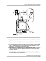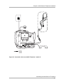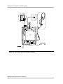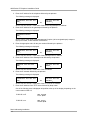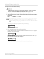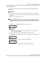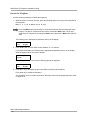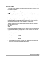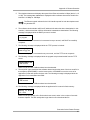
1
4600 Series IP Telephone Installation Guide 555-233-128 Issue 1.7 July 2002 Copyright 2002, Avaya Inc. All Rights Reserved, Printed in U.S.A. Notice Every effort was made to ensure that the information in this book was complete and accurate at the time of printing. However, information is subject to change. Avaya Web Page The world wide web home page for Avaya is: http://www.avaya.com Preventing Toll Fraud Toll fraud is the unauthorized use of your telecommunications system by an unauthorized party (for example, a person who is not a corporate employee, agent, subcontractor, or working on your company’s behalf). Be aware that there is a risk of toll fraud associated with your system and that, if toll fraud occurs, it can result in substantial additional charges for your telecommunications services. Avaya Fraud Intervention If you suspect that you are being victimized by toll fraud and you need technical support or assistance and are in within the United States, call the Technical Service Center Toll Fraud Intervention Hotline at 1.800.643.2353. If you need technical support or assistance and are outside of the United States, contact the equipment vendor from whom you purchased your equipment service maintenance contract. If you need to report toll fraud issues regarding a public telephone, contact the in-country telephone service provider. Providing Telecommunications Security Telecommunications security of voice, data, and/or video communications is the prevention of any type of intrusion to, that is, either unauthorized or malicious access to or use of, your company’s telecommunications equipment by some party. Your company’s “telecommunications equipment” includes both this Avaya product and any other voice/data/video equipment that could be accessed via this Avaya product (that is, “networked equipment”). An “outside party” is anyone who is not a corporate employee, agent, subcontractor, or working on your company’s behalf. Whereas, a “malicious party” is anyone, including someone who may be otherwise authorized, who accesses your telecommunications equipment with either malicious or mischievous intent. Such intrusions may be either to/through synchronous (time-multiplexed and/or circuit-based) or asynchronous (character-, message-, or packet-based) equipment or interfaces for reasons of: • Utilization (of capabilities special to the accessed equipment) • Theft (such as, of intellectual property, financial assets, or toll-facility access) • Eavesdropping (privacy invasions to humans) • Mischief (troubling, but apparently innocuous, tampering) • Harm (such as harmful tampering, data loss or alteration, regardless of motive or intent) Be aware that there may be a risk of unauthorized intrusions associated with your system and/or its networked equipment. Also realize that, if such an intrusion should occur, it could result in a variety of losses to your company, including but not limited to, human/data privacy, intellectual property, material assets, financial resources, labor costs, and/or legal costs. Part 68: Network Registration Number. This equipment is registered with the FCC in accordance with Part 68 of the FCC Rules. It is identified by FCC registration number AV1USA-43058-MFE. Part 68: Answer-Supervision Signaling. Allowing this equipment to be operated in a manner that does not provide proper answer-supervision signaling is in violation of Part 68 Rules. This equipment returns answer-supervision signals to the public switched network when: • Answered by the called station • Answered by the attendant • Routed to a recorded announcement that can be administered by the CPE user This equipment returns answer-supervision signals on all DID calls forwarded back to the public switched telephone network. Permissible exceptions are: • A call is unanswered • A busy tone is received • A reorder tone is received Industry Canada (IC) Interference Information NOTICE: This equipment meets the applicable Industry Canada Terminal Equipment Technical Specifications. This is confirmed by the registration number. The abbreviation, IC, before the registration number signifies that registration was performed based on a Declaration of Conformity indicating that Industry Canada technical specifications were met. It does not imply that Industry Canada approved the equipment. Le Présent Appareil Nomérique n’émet pas de bruits radioélectriques dépassant les limites applicables aux appareils numériques de la class A préscrites dans le reglement sur le brouillage radioélectrique édicté par le Industrie Canada. Trademarks DEFINITY is a registered trademark of Avaya, Inc. MultiVantage is a trademark of Avaya, Inc. Ordering Information Call: Avaya Publications Center U.S. and Canada Voice 1 800 457 1235 Outside U.S. and Canada Voice +1 410 568 3680 U.S. and Canada Fax 1 800 457 1764 Outside U.S. and Canada Fax +1 410 891 0207 Write: GlobalWare Solutions 200 Ward Hill Avenue Haverhill, MA 01835 USA Attention: Avaya Account Manager Email: [email protected] For additional documents, refer to the section in Chapter 1 titled Related Documents. An online copy of this and other related Avaya product documentation can be found at: http:// www.avaya.com/support. Obtaining Products To learn more about Avaya products and to order products, access the Avaya web site at http://www.avaya.com. Or call the following numbers: customers 1 800 451 2100, account executives 1 888 778 1880 (voice) or 1 888 778 1881 (fax). European Union Declaration of Conformity The “CE” mark affixed to the equipment means that it conforms to the referenced European Union (EU) Directives listed below: EMC Directive 89/336/EEC Low-Voltage Directive 73/23/EEC For more information on standards compliance, contact your local distributor. Contents Chapter 1: Introduction ■ ■ ■ ■ ■ ■ Chapter 2: 4600 Series IP Telephone Installation ■ ■ ■ ■ Chapter 3: About This Guide 1-1 Intended Audience 1-1 Document Organization 1-1 Change History 1-2 Terms Used in This Guide 1-2 Conventions Used in This Guide 1-3 Online Documentation 1-4 Related Documents 1-4 Customer Support 1-5 Introduction 2-1 IP Telephone Models 2-1 Software 2-2 Pre-Installation Checklist 2-2 Assembling the 4600 Series IP Telephone 2-4 Powering the 4600 IP Telephone 2-4 Dynamic Addressing Process 2-9 Local Administrative Options ■ ■ ■ ■ Introduction 3-1 Entering Data for Administrative Options 3-1 Pre-Installation Checklist for Static Addressing 3-2 Static Addressing Installation 3-3 QOS Option Setting 3-5 Secondary Ethernet (Hub) Interface Enable/Disable 3-7 Site-Specific Option Number Setting 3-8 Reset System Values 3-9 Restart the Telephone 3-10 Self-Test Procedure 3-11 July 2002 5 Contents Chapter 4: Troubleshooting Guidelines ■ ■ ■ ■ Introduction 4-1 Error Conditions 4-1 DTMF Tones 4-2 Power Interruption 4-2 The View Administrative Option 4-2 Error Messages 4-3 Appendix A: Restart Scenarios ■ 6 July 2002 Scenarios for the Restart Process A-1 Restart the Telephone A-1 Boot file Needs to be Upgraded A-2 Latest Boot File Loaded/No Application File or Application File Needs to be Upgraded A-5 Latest Boot File and System-Specific Application File Already Loaded A-6 Chapter 1: Introduction 1 1 m ao g rP r About This Guide 1 This guide describes how to install the 4600 Series IP Telephone product line and troubleshoot problems with the telephones. The 4600 Series IP Telephone product line is a supplement to the DEFINITY® IP Solutions platform. Unless otherwise indicated, references in this document to the DEFINITY® servers also refer to the MultiVantageTM media servers. Intended Audience 1 This document is intended for personnel installing the 4600 Series IP Telephones. CAUTION: Many of the products mentioned in this document are not supported by Avaya. Care should be taken to ensure there is adequate technical support available for the servers involved, including TFTP and DHCP servers. If the TFTP or DHCP (or other) servers are not functioning correctly, the IP Telephones may be unable to operate correctly. About This Guide 1-1 4600 Series IP Telephone Installation Guide Document Organization 1 The guide contains the following sections: Chapter 1: Introduction Provides an overview of the 4600 Series IP Telephone Installation Guide. Chapter 2: 4600 Series IP Telephone Installation Describes the equipment and resources that are required to properly install and operate the 4600 Series IP Telephones. Provides instructions on installing the telephones out of the box. Chapter 3: Local Administrative Options Describes how to set local administrative options, when instructed to do so by the system or LAN administrator. Chapter 4: Troubleshooting Guidelines Describes error conditions and messages that may occur during the installation of the 4600 Series IP Telephones. Appendix A, Scenarios for the Restart Process Explains the different scenarios possible for the sequence of the restart process. Change History 1 Issue 1.0 This document was issued for the first time in November 2000. Issue 1.1 This version of the document, revised and issued in April 2001, supports through DEFINITY® Release 9. Issue 1.5 This version of the document, revised and issued in June, 2001, supports through DEFINITY® Release 9.5. Issue 1.6 This version of the document, revised and issued in December, 2001 supports through DEFINITY® Release 10, as well as supporting the addition of the 4630 IP Telephone to the 4600 IP Telephone Series. Issue 1.7 This is the current version of this document, issued in July, 2002. This document supports through MultiVantageTM Release 11, as well as supporting the addition of the 4602 and 4620 IP Telephones to the 4600 IP Telephone Series. Terms Used in This Guide 802.1p 802.1Q ARP Document Organization 1-2 1 802.1Q defines a layer 2 frame structure that supports VLAN identification and a QOS mechanism usually referred to as 802.1p, but the content of 802.1p is now incorporated in 802.1D. Address Resolution Protocol, used to verify that the IP address provided by the DHCP server is not in use by another IP Telephone. Chapter 1: Introduction CLAN Control LAN, type of TN799 circuit pack DHCP Dynamic Host Configuration Protocol, an IETF protocol used to automate IP Address allocation and management. DiffServ Differentiated Services, an IP-based QOS mechanism IETF Internet Engineering Task Force, the organization that produces standards for communications on the internet. LAN Local Area Network MAC Media Access Control, ID of an endpoint QoS Quality of Service, used to refer to a number of mechanisms intended to improve audio quality over packet-based networks. RRQ Read Request packet, a message sent from the 4600 Series IP Telephone to the TFTP server, requesting to download the upgrade script and the application file TCP/IP Transmission Control Protocol/Internet Protocol, a network-layer protocol used on LANs and internets. TFTP Trivial File Transfer Protocol, used to provide downloading of upgrade scripts and application files to the IP Telephones. UDP User Datagram Protocol, a connectionless transport-layer protocol. VLAN Virtual LAN Conventions Used in This Guide 1 This guide uses the following textual, symbolic, and typographic conventions to help you interpret information. Symbolic Conventions 1 This symbol precedes additional information about a topic. This information is not required to run your system. CAUTION: This symbol is used to emphasize possible harm to software, possible loss of data, or possible service interruptions. Document Organization 1-3 4600 Series IP Telephone Installation Guide Typographic Conventions 1 This guide uses the following typographic conventions: command Words printed in this type are commands that you enter into your system. device Words printed in this type indicate parameters associated with a command for which you must substitute the appropriate value. For example, when entering the mount command, device must be replaced with the name of the drive that contains the installation disk. Administrative Words printed in bold type are menu or screen titles and labels. “File,” “OK” Words enclosed in double quotation marks refer to items on menus and screens that you select to perform a task. italics Italic type indicates a document that contains additional information about a topic. <Enter> Words enclosed in angle brackets represent a single key that should be pressed. These include <Ctrl>, <Enter>, <Esc>, <Insert>, and <Delete>. Online Documentation 1 The online documentation for the 4600 Series IP Telephones is located at the following URL: http://www.avaya.com/support Related Documents ■ 1 DEFINITY Documentation Release 8.4 This document describes how to administer a DEFINITY switch with Release 8.4 software. This document is provided with the DEFINITY Release 8.4 product. ■ DEFINITY Documentation Release 9 This document describes how to administer a DEFINITY switch with Release 9 software. This document is provided with the DEFINITY Release 9 product. ■ DEFINITY Documentation Release 10 This document describes how to administer a DEFINITY switch with Release 10 software. This document is provided with the DEFINITY Release 10 product. ■ Avaya MultiVantage Software Documentation Release 11 This document describes how to administer a switch with Avaya MultiVantage (Release 11) software, and is available online by selecting Product Documentation at the web site listed above under Online Documentation. Online Documentation 1-4 Chapter 1: Introduction These documents are available on the web site listed above under Online Documentation. ■ 4600 Series IP Telephone Safety Instructions (For 4602/4606/4612/4620/4624/4630 IP Telephones), Issue 1, July 2002 (555-233-779) This document contains important user safety instructions for the 4600 Series IP Telephones. ■ 30A Switched Hub Set Up Quick Reference, Issue 2, July 2002 (Comcode 700234750; Document Number 555-236-700) ■ 4600 Series IP Telephone LAN Administrator’s Guide (555-233-507) This document describes how to administer DHCP, TFTP, and other servers as appropriate for the 4600 Series IP Telephones. It also provides troubleshooting guidelines for the 4600 Series IP Telephones and for the DHCP and TFTP servers, a detailed Management Information Base (MIB) for customers with SNMP tools, and information on how to administer advanced applications for the 4620 and 4630 IP Telephones. ■ 4602 IP Telephone User’s Guide (555-233-780) This document provides detailed information about using the 4602 IP Telephone. ■ 4606 IP Telephone User Guide (555-233-765) (Int’l 555-233-769) This document provides detailed information about using the 4606 IP Telephone. ■ 4612 IP Telephone User Guide (555-233-766) (Int’l 555-233-770) This document provides detailed information about using the 4612 IP Telephone. ■ 4620 IP Telephone User Guide (555-233-781) This document provides detailed information about using the 4620 IP Telephone. ■ 4624 IP Telephone User Guide (555-233-768) (Int’l 555-233-771) This document provides detailed information about using the 4624 IP Telephone. ■ 4630 IP Telephone User Guide (555-233-764) This document provides detailed information about using the 4630 IP Telephone. Customer Support 1 For support for your 4600 Series IP Telephones, call the Avaya support number provided to you by your Avaya representative or Avaya reseller. Information about Avaya products can be obtained at the following URL: http://www.avaya.com/support Customer Support 1-5 4600 Series IP Telephone Installation Guide Customer Support 1-6 Chapter 2: 4600 Series IP Telephone Installation 2 2 m ao g rP r Introduction 2 The 4600 Series IP Telephone product line uses Internet Protocol (IP) technology with Ethernet interfaces. The IP telephones supplement the existing DEFINITY®/MultiVantageTM IP Solutions platform. The 4600 Series IP Telephones support DHCP and TFTP over IPv4/UDP which enhance the administration and servicing of the phones. These phones use DHCP to obtain dynamic IP addresses and TFTP to download new versions of software for the phones. The 4600 Series IP Telephones provide the ability to have one IP connection on the desktop for both a telephone set and a PC using the telephone’s built-in hub. For information on Voice over IP, see the 4600 Series IP Telephone LAN Administrator’s Guide. In compliance with Australian law, the following information is provided: This equipment shall be installed and maintained by trained service personnel. All the input/output ports are classified as Safety Extra Low Voltage (SELV, in the meaning of IEC 60950). To maintain safety compliance when connecting the equipment electrically to other equipment, the interconnecting circuits shall be selected to provide continued conformance of clause 2.3 for SELV circuits (generally, double/reinforced insulation to 240Vac rms to any primary/mains circuitry and 120Vac rms to any Telecommunication network circuitry). To ensure the above conditions are adhered to, only interconnect the equipment with the already approved/certified equipment. IP Telephone Models 2 There are six telephone set models defined in the 4600 Series IP Telephone family: ■ ■ ■ 4602 IP Telephone 4606 IP Telephone 4612 IP Telephone ■ ■ ■ 4620 IP Telephone 4624 IP Telephone 4630 IP Telephone This document describes the installation of these phones. For details about using the features provided by the phones, refer to the documentation for each phone. Introduction 2-1 4600 Series IP Telephone Installation Guide Software 2 As shipped from the factory, the 4600 Series IP Telephones may not contain sufficient software for registration and operation. When the phone is first plugged in, a software download from a TFTP server is initiated. This gives the phone the functionality of a DEFINITY/MultiVantage IP Telephone. For downloads of software upgrades, DEFINITY/MultiVantage provides the capability for a remote restart of the IP telephone. As a consequence of restarting, the phone automatically restarts reboot procedures which result in a download, if new software is available. Pre-Installation Checklist 2 Before plugging in the 4600 Series IP Telephone, verify that all of the following requirements have been met. Failure to do so will prevent the telephone from working and may have a negative impact on your network. Print copies of this checklist for each server and IP Telephone. Requirements to Verify about the Network 1. The DEFINITY/MultiVantage switch is administered for IP Telephones and has software for Release 8.4 or later. MultiVantage Release 11 supports the 4602 and 4620 IP Telephones. For Release 1.1 of the 4600 Series Telephones, the DEFINITY switch must have Release 9 software. For Release 1.5 of the 4600 Series Telephones, the DEFINITY switch must have Release 9.5 software. For Release 1.6 of the 4600 IP Series Telephones, and for support of the 4630 IP Telephone, the DEFINITY switch must have Release 10 software. For Release 1.7 of the 4600 IP Series Telephones, and for support of the 4602 and 4620 IP Telephones, the DEFINITY/MultiVantage switch must have Release 11 software. 2. The following two circuit packs are installed on the switch: ■ TN2302 IP Media Processor circuit pack ■ TN799B Control-LAN (CLAN) circuit pack 3. Ensure that all required parameters are configured correctly. For MultiVantage, see the MultiVantage documentation. For the DHCP and TFTP, see “Troubleshooting Guidelines” in the 4600 Series IP Telephone LAN Administrator’s Guide. 4. The DHCP server and application are administered as described in the 4600 Series IP Telephone LAN Administrator’s Guide. 5. The TFTP server and application are administered as described in the 4600 Series IP Telephone LAN Administrator’s Guide. 6. The upgrade script and application files are loaded correctly on the TFTP server. 7. If applicable, the LDAP, HTTP, DNS, Voice Mail, and/or Web Messaging servers are administered as described in the 4600 Series IP Telephone LAN Administrator’s Guide. This is a consideration only for 4630 installations. Pre-Installation Checklist 2-2 Chapter 2: 4600 Series IP Telephone Installation 8. If applicable, the WML server is administered as described in the 4600 Series IP Telephone LAN Administrator’s Guide. This is a consideration only for 4620 installations. Any or all of the servers mentioned above in items 4-8 can be co-resident on the same hardware. Requirements to Verify for Each IP Telephone 9. You have an extension number and a DEFINITY/MultiVantage security code (password) for each IP Telephone. 10. A Category 5 LAN jack is available at each phone site. 11. Electrical power is provided to each telephone by a Telephone Power Module (DC power jack) (must be ordered separately), unless the 4602/4606/4612/4620/4624 will be supplied by IEEE-standard power from the LAN, in which case no power module is required. The 4630 IP Telephone does not support IEEE-standard power, and therefore requires the Power Module. 12. 1 Category 5 modular line cord is available for the connection between the IP Telephone and the PC. 13. Verify that the 4600 Series IP Telephone package includes the following components: ■ 1 telephone set ■ 1 AB1C handset or AK1A handset (for 4602 or 4620 IP Telephones) ■ 1 H4DU 9-foot long (when extended) 4-conductor coiled handset cord, plugged into the telephone and the handset ■ 1 Category 5 modular line cord for the connection from the IP Telephone to the Ethernet wall jack ■ 4600 Series IP Telephone Safety Instructions (For 4602/4606/4612/4624/4620/ 4630 IP Telephones), (555-233-779) ■ Power Brick (4630 IP Telephones only) ■ Stylus (4630 IP Telephones only) Optional Items for Some IP Telephones 14. If applicable to your current installation, verify that the following equipment is present: ■ 30A Switched Hub (applicable to the 4606/4612/4624/4630 only) Pre-Installation Checklist 2-3 4600 Series IP Telephone Installation Guide Assembling the 4600 Series IP Telephone 2 Powering the 4600 IP Telephone 2 There are two options for powering the 4602/4606/4612/4620/4624 IP Telephones, and only one way to power the 4630 IP Telephone. All 4600 Series IP Telephones can be locally powered with a Telephone Power Module (DC power jack), available separately. In addition, the 4602/4606/4612/ 4620/4624 IP Telephones support IEEE 802.3af-standard LAN-based power. Before installing a 4602/4606/4612/4620/4624 IP Telephone, verify with the LAN administrator whether the LAN supports IEEE 802.3af, and if so, whether the telephone should be powered locally or via the LAN. Use the following procedure to assemble the 4600 Series IP Telephone. If your installation includes a 30A Switched Hub, follow the installation instructions included in the Switched Hub box. The last step in assembling the 4600 Series IP Telephone must be applying power, either by plugging the power cord into the power source (local powering) or plugging the modular line cord into the Ethernet wall jack (IEEE powering). Be careful to use the correct jack when plugging in the telephone. The jacks are located on the back of the telephone housing. The left jack is for the primary Ethernet cable and the right jack is for the secondary Ethernet cable (connected to the PC). These jacks are flanked by icons to represent their correct use. Refer to Figure 2-1 for an illustration of how to connect cords to jacks on the 4602/4606/4612/4624 IP Telephones. Refer to Figure 2-2 and Figure 2-3 for illustrations of cord to jack connection options on the 4620 IP Telephone, and to Figure 2-4 for an illustration of how to connect cords and jacks on the 4630 IP Telephone. Assembling the 4600 Series IP Telephone 2-4 Chapter 2: 4600 Series IP Telephone Installation DC = optional facultatif optionale opcional (DSS 4624) Figure 2-1. Connection Jacks on a 4602/4606/4612/4624 IP Telephone 1. Plug one end of the H4DU 4-conductor coiled handset cord into the telephone and the other end into the handset. 2. Plug one end of the first Category 5 modular line cord into the Ethernet jack of the PC and the other end into the secondary Ethernet jack on the 4600 Series IP Telephone. 3. Plug one end of the second Category 5 modular line cord into the Ethernet jack on the 4600 Series IP Telephone and the other end into the Ethernet wall jack. If the telephone is to be IEEE-powered, you are finished. Do not proceed to Step 4. 4. If the telephone is to be powered locally in the United States and Canada, plug the barrel connector on the power cord into the 4600 Series IP Telephone and the plug on the power cord into the wall socket. If the telephone is to be powered locally outside of the United States and Canada, connect the 1151 power brick to the power cable, plug the barrel connector to the 4600 Series IP Telephone and the plug into the wall socket. Assembling the 4600 Series IP Telephone 2-5 4600 Series IP Telephone Installation Guide 1151B = optional facultatif optionale opcional Figure 2-2. Connection Jacks on a 4620 IP Telephone - Option A Assembling the 4600 Series IP Telephone 2-6 Chapter 2: 4600 Series IP Telephone Installation = optional facultatif optionale opcional Figure 2-3. Connection Jacks on a 4620 IP Telephone - Option B Assembling the 4600 Series IP Telephone 2-7 4600 Series IP Telephone Installation Guide DC = optional facultatif optionale opcional Figure 2-4. Connection Jacks on a 4630 IP Telephone Assembling the 4600 Series IP Telephone 2-8 Chapter 2: 4600 Series IP Telephone Installation Dynamic Addressing Process 2 Before beginning this process, you must have an extension number for the IP Telephone and the DEFINITY/MultiVantage security code (password) for that extension. The following description of the process of installing the IP telephones assumes that the process is executed successfully. Only an initial installation (out of the box) is described. For errors that may be encountered during the process and the messages displayed, see Chapter 4: Troubleshooting Guidelines. When you plug the IP Telephone set into the Ethernet wall jack, the following process takes place. If the application has already been downloaded, the whole process takes approximately 1 to 2 minutes after the phone is plugged in. For an initial installation (including download of the application) the process may take 5 - 10 minutes. The duration is based on LAN loading, how many phones are being installed at once, and similar factors. 1. The telephone activates the Ethernet line interface, the secondary Ethernet jack, and dial pad input (to allow the invocation of procedures) as soon as possible after power-up or a reset. The telephone detects and displays the speed of the Ethernet interface in Mbps (that is, 10 or 100). The message No Ethernet is displayed until the software determines whether the interface is 10 Mbps or 100 Mbps. The Ethernet speed indicated is the LAN interface speed for both the telephone and any attached PC. 2. The IP telephone sends a request to the DHCP server and invokes the DHCP process. The following message is displayed: DHCP: s secs, * to program where s is the number of seconds that have elapsed since DHCP was invoked. 3. The DHCP server provides IP addresses for the following: ■ The IP Telephone ■ The TFTP server ■ The TN799 Control-LAN (CLAN) circuit pack on the call server 4. The IP Telephone connects to the TFTP server and looks for an upgrade script file. 5. The TFTP server sends an upgrade script, telling the phone what it is. Dynamic Addressing Process 2-9 4600 Series IP Telephone Installation Guide Since the read request packet may have to be sent several times, each time the RRQ message is sent, the following message is displayed: TFTP: s secs 6. While the upgrade script file is being downloaded, the following message is displayed: 46xxUPGRADE.SCR n KB received where n is the number of KBs received from the TFTP server. 7. While the application file is downloaded to the IP Telephone, the following message is displayed: filename n KB received where n is the number of KBs received from the TFTP server. 8. While the application file is saved in flash memory, the following message is displayed: Saving to flash 1%, 1 secs with the percentage of the file and the number of elapsed seconds incremented as the application file is stored in flash memory. 9. The phone contacts the DEFINITY/MultiVantage server and attempts to log in. The following prompt for an extension is displayed: Extension=nnnnnn #=OK NEW=_ 10. Enter a new extension, ending with the # button. If the extension is not in use, the following prompt for a password is displayed: Password=_ #=OK 11. Enter the password, ending with the # button. While the telephone’s extension is visible as you enter it, the password is displayed as asterisks. 12. The system determines whether the extension is in use. 13. Successful completion of this process causes the dial tone to be available. The IP Telephone has been installed successfully. Dynamic Addressing Process 2-10 Chapter 3: Local Administrative Options 3 3 m ao g rP r Introduction 3 After you have successfully installed an IP Telephone, you may be instructed to administer one of the following options. To set parameters for all 4600 Series IP Telephones that download their upgrade script and application files from the same TFTP server, you can modify the upgrade script. See the section on "Customizing the Upgrade Script File" in Chapter 4 of the 4600 Series IP Telephone LAN Administrator’s Guide. WARNING: Perform these procedures only if instructed to do so by the system or LAN administrator. Static administration of these options will cause upgrades to work differently than if they are administered dynamically. The values assigned to options in static administration will not be changed by upgrade scripts. They will remain active for the IP Telephone until a new boot file is downloaded. Aside from SSON, these option-setting procedures are to be used only if you are using static addressing, and, as always, only if instructed by the system or LAN administrator. Do not use these option-setting procedures (aside from SSON) if you are using DHCP (the Dynamic Addressing Process as indicated in Chapter 2, Dynamic Addressing Process). Entering Data for Administrative Options 3 This section describes how to enter data for the administrative options. 1. All local procedures are invoked by pressing the Hold or Mute button, up to 7 numeric dial pad buttons, and the # button. Since the 4630 IP Telephone does not have a dedicated Hold button, you must use the Mute button to access these options on the 4630 IP Telephone. A 6-second timeout is in effect between button presses after the Hold button is pressed; if a valid button is not pressed within 6 seconds of the previous button, the collected digits are discarded, and no administrative option is invoked. Introduction 3-1 4600 Series IP Telephone Installation Guide 2. Attempts to enter invalid data are rejected, and the phone emits an error beep. 3. If a numeric digit is entered for a value or for a field of an IP address or subnet mask after only a zero has been entered, the new digit will replace the zero. 4. Press the # button to go to the next step. 5. To backspace within a field, see the chart below, depending on the type of phone being installed: IP Telephone # Backspace Alternative 4602 Speaker button 4606 Conference button 4612 Left-most softkey or Previous button 4624 Left-most softkey or Previous button 4620 Left-most softkey 4630 Headset button When you press the applicable button or key, the most recently entered digit or period is erased from the display, and the cursor is left in the erased character’s former position. Pre-Installation Checklist for Static Addressing 3 Before performing static addressing on the 4600 Series IP Telephone, verify that all of the requirements listed in the Requirements to Verify about the Network section of the Pre-Installation Checklist in Chapter 2 have been met (other than item 4 referring to the DHCP server). In addition, you must have the values for the following parameters. Failure to do so may cause errors during data entry, which will prevent the telephone from working and may have a negative impact on your network. Print copies of this checklist for each subnet. 1. The IP Address of the call server/gatekeeper 2. The transport layer port number of the Address of the Management Complex (call server/gatekeeper). Although this may be a value between 0 and 65535, the default value is 1719 and should not be changed unless this conflicts with an existing port assignment. 3. The IP Address of the gateway/router Pre-Installation Checklist for Static Addressing 3-2 Chapter 3: Local Administrative Options 4. The IP netmask 5. The IP Address of the TFTP server Static Addressing Installation 3 The usual way to assign IP addresses to IP Telephones is the automatic method described in Chapter 2, Dynamic Addressing Process. There may be times, however, when manual assignment of IP addresses is desired WARNING: Static addressing is necessary when a DHCP server is unavailable. Due to the difficulties associated with static addressing, it is very strongly recommended that a DHCP server be installed and that static addressing be avoided. The displays on the 4602, 4612, 4620, 4624, and 4630 IP Telephones accommodate up to 24 characters per line. The display on the 4606 telephone accommodates up to 16 characters per line. Here and in the examples below, the example on the left shows the display on the 4602, 4612, 4620, 4624, and 4630 telephones, and the example on the right shows the display on the 4606 telephone. Use the following procedure to invoke manual address information programming. 1. Start manual address programming by performing one of the following steps: a. During normal DHCP processing, press the * key before the DHCP process completes. or b. While the phone is on-hook and idle, press the following sequence of keys on the faceplate of the telephone: Mute 2 3 3 7 # (Mute A D D R #) Press the Mute button momentarily. Do not press this button while pressing other keys/ buttons. The 4630 IP Telephone does not have a dedicated Hold button; for all other 4600 Series IP Telephones, pressing the Hold button instead of the Mute button will also work. The following message is displayed: Phone=nnn.nnn.nnn.nnn New=_ or nnn.nnn.nnn.nnn Phone=_ where “nnn.nnn.nnn.nnn” is the value of the telephone. Static Addressing Installation 3-3 4600 Series IP Telephone Installation Guide 2. Enter the IP address for the telephone followed by the # button. The following message is displayed: CallSv=nnn.nnn.nnn.nnn New=_ or nnn.nnn.nnn.nnn CallSv=_ where “nnn.nnn.nnn.nnn” is the value of the call server/gatekeeper IP address. 3. Enter the IP address for the gatekeeper followed by the # button. The following message is displayed: CallSvPort=nnnnn New=_ where “nnnnn” is the value of the Management Complex (call server/gatekeeper) transportlayer port number, a value between 0 and 65535. 4. Enter the appropriate value for the port number followed by the # button. The following message is displayed: Router=nnn.nnn.nnn.nnn New=_ or nnn.nnn.nnn.nnn Router=_ where “nnn.nnn.nnn.nnn” is the value of the Gateway/router IP address. 5. Enter the IP address of the Gateway/router followed by the # button. The following message is displayed: Mask=nnn.nnn.nnn.nnn New=_ or nnn.nnn.nnn.nnn Mask=_ where “nnn.nnn.nnn.nnn” is the value of the IP netmask. 6. Enter the IP netmask followed by the # button. The following message is displayed: FileSv=nnn.nnn.nnn.nnn New=_ or nnn.nnn.nnn.nnn FileSv=_ where “nnn.nnn.nnn.nnn” is the value of the TFTP server IP address. 7. Enter the IP address of the TFTP server followed by the # button. One of the following texts is displayed left-justified at the top of the display, depending on the current status of 802.1Q: If 802.1Q is off: 802.1Q=off 1=on #=OK If 802.1Q is on: 802.1Q=on 0=off #=OK Static Addressing Installation 3-4 Chapter 3: Local Administrative Options 8. Press the 1 or 0 button to turn 802.1Q on or off respectively. The display is updated to show the current status of 802.1Q. Press the # button to continue the procedure without changing the displayed status of 802.1Q The following text is displayed left-justified at the top of the display: VLAN ID=dddd New=_ where dddd is the value of the 802.1 VLAN ID. 9. Enter a valid value (between 0 and 4095) for the new value of the 802.1 VLAN ID. The following message is displayed: Save new values? *=no #=yes 10. Press the # button to save the new values you have entered. The following message is displayed: New values being saved Once the new values are stored, the telephone is reset. If a new boot program is downloaded from the TFTP server after you enter static addressing information, you will need to reenter your static addressing information. QOS Option Setting 3 Administering QOS options is not mandatory, but it is highly recommended. Use the following procedure to set Quality of Service (QOS) options. 1. While the phone is on-hook and idle, press the following sequence of keys on the faceplate of the telephone: Mute 7 6 7 # (Mute Q O S #) Press the Mute button momentarily. Do not press this button while pressing other keys/ buttons. The 4630 IP Telephone does not have a dedicated Hold button; for all other 4600 Series IP Telephones, pressing the Hold button instead of the Mute button will also work. The following text is displayed left-justified at the top of the display: L2 audio=d New=_ where d is the value of the 802.1 audio parameter. Static Addressing Installation 3-5 4600 Series IP Telephone Installation Guide 2. Enter a valid value (between 0 and 7) for the new value of the 802.1 audio parameter. The following text is displayed left-justified at the top of the display: L2 signaling=d New=_ where d is the value of the 802.1 signaling parameter. 3. Enter a valid value (between 0 and 7) for the new value of the 802.1 signaling parameter. The following text is displayed left-justified at the top of the display: L3 audio=dd New=_ where dd is the value of the Differential Services audio parameter. 4. Enter a valid value (between 0 and 63) for the new value of the Differential Services audio parameter. The following text is displayed left-justified at the top of the display: L3 signaling=dd New=_ where dd is the value of the Differential Services signaling parameter. 5. Enter a valid value (between 0 and 63) for the new value of the Differential Services signaling parameter. If no new values were entered during this procedure, the following text is displayed left-justified at the top of the display: No new values. #=OK Press # to terminate the procedure. If new values were entered during this procedure, the following text is displayed left-justified at the top of the display: Save new values? *=no #=yes Press the * button to terminate the procedure, or the # button to save the new values. If you press the # button, the following text is displayed: New values being saved The new values are saved, and the user interface is restored to its previous state. Static Addressing Installation 3-6 Chapter 3: Local Administrative Options Secondary Ethernet (Hub) Interface Enable/Disable 3 Use the following procedure to enable or disable the hub interface. The default for the hub interface is enabled. 1. While the phone is on-hook and idle, press the following sequence of keys on the faceplate of the telephone: Mute 4 6 8 # (Mute I N T #) Press the Mute button momentarily. Do not press this button while pressing other keys/ buttons. The 4630 IP Telephone does not have a dedicated Hold button; for all other 4600 Series IP Telephones, pressing the Hold button instead of the Mute button will also work. One of the following texts is displayed left-justified at the top of the display, depending on the current value of the hub: If PHY2=enabled: PHY2=enabled 0=disable #=OK If PHY2=disabled: PHY2=disabled 1=enable #=OK 2. Press the 1 or 0 button to enable or disable the hub interface respectively, or the # button to leave the current value. The following text is displayed left-justified at the top of the display: Save new value? *=no #=yes Press the * button to terminate the procedure, or the # button to save the new values. If you press the # button, the following text is displayed. New value being saved The new values are saved, and the user interface is restored to its previous state. Static Addressing Installation 3-7 4600 Series IP Telephone Installation Guide Site-Specific Option Number Setting 3 WARNING: Do not perform this procedure if you are using static addressing. Perform this procedure only if you are using DHCP and the LAN administrator instructs you to do this. Use the following procedure to set the Site-Specific Option Number (SSON). 1. While the phone is on-hook and idle, press the following sequence of keys on the faceplate of the telephone: Mute 7 7 6 6 # (Mute S S O N #) Press the Mute button momentarily. Do not press this button while pressing other keys/ buttons. The 4630 IP Telephone does not have a dedicated Hold button; for all other 4600 Series IP Telephones, pressing the Hold button instead of the Mute button will also work. The following text is displayed left-justified at the top of the display: SSON=ddd New=_ where ddd is the value of SSON. 2. Enter a valid value (between 128 and 255) for the SSON. If a value different from the current value of SSON is entered, the following text is displayed left-justified at the top of the display: Save new value? *=no #=yes Press the * button to terminate the procedure, or the # button to save the new value. If you press the # button, the following text is displayed: New value being saved The new value is saved, and the user interface is restored to its previous state. Static Addressing Installation 3-8 Chapter 3: Local Administrative Options Reset System Values 3 Use the following procedure to reset all system initialization values to the application software default values. WARNING: This procedure erases all static information, without any possibility of recovering the data. 1. While the phone is on-hook and idle, press the following sequence of keys on the faceplate of the telephone: Mute 7 3 7 3 8 # (Mute R E S E T #) Press the Mute button momentarily. Do not press this button while pressing other keys/ buttons. The 4630 IP Telephone does not have a dedicated Hold button; for all other 4600 Series IP Telephones, pressing the Hold button instead of the Mute button will also work. The following text is displayed left-justified at the top of the display: Reset values? *=no #=yes WARNING: As soon as you press the # button, all static information will be erased, without any possibility of recovering the data. 2. Press the # button to reset values to their defaults or the * button to continue. The following text is displayed left-justified at the top of the display while the system values are reset to defaults: Resetting values. Once the system values are reset, the following prompt is displayed: Restart phone? *=no #=yes 3. Press the * key to terminate the procedure without restarting the telephone. Static Addressing Installation 3-9 4600 Series IP Telephone Installation Guide Restart the Telephone 3 Use the following procedure to restart the telephone. 1. While the phone is on-hook and idle, press the following sequence of keys on the faceplate of the telephone: Mute 7 3 7 3 8 # (Mute R E S E T #) Press the Mute button momentarily. Do not press this button while pressing other keys/ buttons. The 4630 IP Telephone does not have a dedicated Hold button; for all other 4600 Series IP Telephones, pressing the Hold button instead of the Mute button will also work. The following text is displayed left-justified at the top of the display: Reset values? *=no #=yes 2. Press the # button to reset values to their defaults, or * to continue. If you press the # button, the following text is displayed left-justified at the top of the display while the system values are reset to defaults: Resetting values. Once the system values are reset, the following prompt is displayed: Restart phone? *=no #=yes 3. Press the * key to terminate the procedure without restarting the telephone. Press the # key to restart the telephone. The remainder of the procedure depends on the status of the boot and application files. Refer to Appendix A. Static Addressing Installation 3-10 Chapter 3: Local Administrative Options Self-Test Procedure 3 To invoke 4600 Series IP Telephone self-test procedures, press the following sequence of keys on the faceplate of the telephone: Mute 8 3 7 8 # (Mute T E S T #) Press the Mute button momentarily. Do not press this button while pressing other keys/ buttons. The 4630 IP Telephone does not have a dedicated Hold button; for all other 4600 Series IP Telephones, pressing the Hold button instead of the Mute button will also work. The telephone illuminates each column of red and green LEDs associated with administrable buttons sequentially for 0.5 second, from left to right across the telephone, in a repeating cycle. The Speaker/Mute LED and the message waiting LED are illuminated along with the closest column of LEDs. Buttons generate a button click if pressed, but do not generate any systemspecific signaling messages, DTMF, or invoke speakerphone or mute operation. Telephones with displays display the following text, left-justified at the top of the display, for 1 second after self-test is invoked: Self test #=end For 4602/4606/4612/4620/4624 IP Telephones, a block character (all pixels on) is then displayed in all display character locations for 5 seconds. Display of the block character is used to find bad display pixels. For a 4630 IP Telephone, all pixels are on, and the display should be solid white for 5 seconds. One of the following is displayed: If self-test passes: Self test passed #=end If self-test fails: Self test failed #=end 4. To terminate the self-test, generate confirmation tone, and return the user interface to the previous state, press the # button on the dial pad at any time. Static Addressing Installation 3-11 4600 Series IP Telephone Installation Guide Static Addressing Installation 3-12 Chapter 4: Troubleshooting Guidelines 4 4 P Introduction 4 This chapter describes problems that may occur during installation of the 4600 Series IP Telephones and possible ways of resolving these problems. For problems that occur during normal operation, see “Troubleshooting Guidelines” in the 4600 Series IP Telephone LAN Administration Guide. This chapter is organized in the following sections: ■ Descriptions of error conditions and methods for resolving them. ■ The use of the View option to view values of system. ■ Error messages and methods for resolving them. Error Conditions 4 There are four areas where installers can troubleshoot problems before seeking assistance from the system or LAN administrator: 1. Check the wiring (power and Ethernet) for the following: ■ ■ Whether all components are plugged in correctly. Check LAN connectivity in both directions to all servers (DHCP, TFTP, DEFINITY®/ MultiVantageTM) 2. If you are using static addressing, do the following: ■ Use the View command to find the names of the files being used and verify that these filenames match those on the TFTP server. Check on the Avaya website to verify whether the correct files are being used. ■ Use the ADDR option to verify IP addresses. ■ Use the QOS option to verify QoS parameters. Refer to Chapter 3 of the 4600 Series IP Telephone Installation Guide. Introduction 4-1 4600 Series IP Telephone Installation Guide 3. If the 4600 Series IP Telephone is not communicating with the system (DHCP, TFTP, or DEFINITY®/MultiVantageTM), make a note of the last message that was displayed and consult the system administrator. 4. If you are expecting the telephone to be IEEE-powered, verify with the LAN administrator that IEEE power is indeed supported on the LAN. DTMF Tones 4 The failure to hear DTMF tones sent by a far-end 4600 Series IP Telephone does not require any action on the user’s part. The TN2302AP board does not pass in-band DTMF tones. Power Interruption 4 If power to a 4600 Series IP Telephone is interrupted while the telephone is saving the application file, the TFTP application may hang. If this occurs, restart the TFTP server. The View Administrative Option 4 If you are using static addressing and encounter problems, use the following procedure to verify the current values of system parameters and file versions. Also use the ADDR option to view IP addresses (see Static Addressing Installation in Chapter 3). These may have been entered incorrectly. Verify whether you were provided with correct IP addresses. 1. While the phone is on-hook and idle, press the following sequence of keys on the faceplate of the telephone: Mute 8 4 3 9 # (Mute V I E W #) Press the Mute button momentarily. Do not press this key while pressing other keys. The 4630 IP Telephone does not have a dedicated Hold button; for all other 4600 Series IP Telephones, pressing the Hold button instead of the Mute button will also work. The following text is displayed left-justified at the top of the display: View settings *=next #=exit 2. Press the * button at any time during viewing to display the next name and system value pair from the list below, returning to the first pair after the last pair has been displayed. Press the # button at any time during viewing to terminate the procedure and restore the user interface to its previous state. The View Administrative Option 4-2 Chapter 4: Troubleshooting Guidelines The names and values are displayed in the following order: Table 4-1. Parameter Values Name System Value Format Model 46ccDccc up to 8 ASCII graphics characters Market domestic export Only one value is displayed Phone SN cccccccccccc cccccccc Phone Serial Number, up to 18 ASCII graphic characters PWB SN cccccccccccc cccccccc Printed Wiring Board (circuit board) Serial Number, up to 18 ASCII graphic characters PWB comcode ccccccccc 9 ASCII numbered characters MAC address 00:60:1D:hh:hh:hh Each octet of the MAC address is displayed as a pair of hexadecimal numbers. filename1.exe up to 16 ASCII graphic characters. filename2.exe Out of the box, there will be only one filename.exe. After installation, there should be two filenames. If there is only one, installation has failed. Verify the problem, and then re-install the telephone. Error Messages 4 The 4600 Series IP Telephones issue messages in English only. The IP Telephones also display messages from the switch, which outside the United States may issue messages in the local language. Table 4-2. Possible Error Messages During Installation of 4600 Series IP Telephones Error Message Checksum error Cause/Resolution CAUSE: Downloaded application file was not downloaded or saved correctly. RESOLUTION: The telephone automatically resets and attempts to re-initialize. Error Messages 4-3 4600 Series IP Telephone Installation Guide Table 4-2. Possible Error Messages During Installation of 4600 Series IP Telephones— Continued Error Message DHCP: CONFLICT * to program Cause/Resolution CAUSE: At least one of the IP address offered by the DHCP server conflicts with another address. RESOLUTION: Review DHCP server administration to identify duplicate IP address(es) Discovering... CAUSE: The 46xx telephone is attempting to find a DHCP server. RESOLUTION: If this message appears for more than a few seconds, verify with the LAN Administrator that a DHCP server is appropriately administered on the network. If there is not supposed to be a DHCP server, you must "break into" the Discovering process and use static addressing as explained on page 3-3. To break into the Discovering process, press the # button, and when you see the "100Mbs" or "10Mbs" message, quickly press the * (asterisk) button. Extension Error CAUSE: The PBX does not recognize the extension entered. RESOLUTION: Confirm the extension is correct and is correctly administered on the switch. Then try registration again, taking particular care to enter the extension accurately. Extension in Use CAUSE: The PBX detects an extension conflict with an existing set. RESOLUTION: Ensure the PBX is properly administered to expect the appropriate telephone for the relevant extension. Failed to set phone IP address CAUSE: The 4600 Series Telephone was originally installed on one switch with Static Addressing, and has subsequently been installed on another switch with an active DHCP server assigning dynamic IP addresses. RESOLUTION: Reset the telephone. File too large Cannot save file CAUSE: The telephone does not have sufficient room to store the downloaded file. RESOLUTION: Verify the proper filename is administered in the TFTP script file, and that the proper application file is located in the appropriate location on the TFTP server. Gateway Error CAUSE: DEFINITY Release 8.4 does not have an H.323 station extension for this telephone. RESOLUTION: On the station administration screen, ensure the DCP set being aliased for this IP telephone has an H.323 station extension administered, in accordance with switch administration instructions. Error Messages 4-4 Chapter 4: Troubleshooting Guidelines Table 4-2. Possible Error Messages During Installation of 4600 Series IP Telephones— Continued Error Message Hardware failure Cause/Resolution CAUSE: Hardware failure prevented downloading of application file. RESOLUTION: Replace telephone. Incompatible CAUSE: This release of DEFINITY does not support the current version of the IP Telephone. RESOLUTION: Upgrade to the current version of MultiVantage software. IP Address in use by another CAUSE: The telephone has detected an IP address conflict. No Ethernet CAUSE: When first plugged in, the IP Telephone is unable to communicate with the Ethernet. RESOLUTION: Verify administration to identify duplicate IP address(es). RESOLUTION: Verify the connection to the Ethernet jack, verify the jack is Category 5, verify power is applied on the LAN to that jack, etc. No file server address CAUSE: The TFTP server IP address in the IP telephone’s memory is all zeroes. RESOLUTION: Depending on the specific requirements of your network, this may not be an error. If appropriate, either administer the DHCP server with the proper address of the TFTP server, or administer the telephone locally using the ADDR option as detailed in Chapter 3, Static Addressing Installation. Password Error CAUSE: The PBX does not recognize the password entered. RESOLUTION: Confirm the password is correct, then try registration again, taking particular care to enter the password accurately. System busy CAUSE: Most likely, the number of IP endpoints on the PBX is already at maximum, Less likely, network resource is unavailable. RESOLUTION: The telephone was attempting to access a network resource (DHCP server, TFTP server, or the PBX) and was not successful. The resource being called upon should be checked for its availability. If it appears operational and properly linked to the network, verify addressing is accurate and a communication path exists in both directions between the telephone and the resource. Error Messages 4-5 4600 Series IP Telephone Installation Guide Table 4-2. Possible Error Messages During Installation of 4600 Series IP Telephones— Continued Error Message System Error Cause/Resolution CAUSE: The PBX has an unspecified problem. RESOLUTION: Consult DEFINITY/MultiVantage Administration and Troubleshooting documentation. Timeout Error CAUSE: Protocol timeout error. RESOLUTION: Retry. If failure continues, check network congestion, addresses, etc. to identify cause of timeout. Undefined Error CAUSE: The PBX has rejected registration for an unspecified reason. RESOLUTION: Consult DEFINITY/MultiVantage Administration and Troubleshooting documentation. Resource Error CAUSE: The PBX rejects the registration request. RESOLUTION: Verify DEFINITY/MultiVantage Administration to ensure the telephone’s proper IP address, extension, and password are being used. Wrong Set Type CAUSE: The PBX does not recognize the set type. RESOLUTION: Ensure the PBX is properly administered to expect the appropriate telephone for the IP address and extension. Error Messages 4-6 Appendix A: Restart Scenarios A A m ao g rP m r Scenarios for the Restart Process 4 The sequence of the restart process depends on the status of the boot and application files. This appendix explains the different scenarios possible. Restart the Telephone 4 Use the following procedure to restart the telephone. 1. While the phone is on-hook and idle, press the following sequence of keys on the faceplate of the telephone: Mute 7 3 7 3 8 # (Mute R E S E T #) Press the Mute button momentarily. Do not press this key while pressing other keys. The 4630 IP Telephone does not have a dedicated Hold button; for all other 4600 Series IP Telephones, pressing the Hold button instead of the Mute button will also work. The following text is displayed left-justified at the top of the display: Reset values? *=no #=yes 2. Press the # button to continue the procedure. The following text is displayed left-justified at the top of the display while the system values are reset to defaults: Resetting values. Once the system values are reset, the following prompt is displayed: Restart phone? *=no #=yes Scenarios for the Restart Process A-1 4600 Series IP Telephone Installation Guide 3. Press the * key to terminate the procedure without restarting the telephone. Press the # key to restart the telephone. The remainder of the procedure depends on the status of the boot and application files. Refer to the table below. If this condition applies See Boot file Needs to be Upgraded page A-2 Latest Boot File Loaded/No Application File or Application File Needs to be Upgraded page A-5 Latest Boot File and System-Specific Application File Already Loaded page A-6 Boot file Needs to be Upgraded 4 This should almost never happen. 1. The following message is displayed: Restarting... 2. While the hardware is being initialized, the following message is displayed: Initializing 3. While either the application file (if there is one) or the boot code is uncompressed into RAM, the following message is displayed: Loading ....************ Since this takes a while, asterisks, then periods, then asterisks are displayed on the second line to indicate that something is happening. 4. When control is passed to the software that was just loaded, the following message is displayed: Starting... Scenarios for the Restart Process A-2 Appendix A: Restart Scenarios 5. The telephone detects and displays the speed of the Ethernet interface in Mbps (that is, 0, 10 or 100). The message No Ethernet is displayed until the software determines whether the interface is 10 Mbps or 100 Mbps. The Ethernet speed indicated is the LAN interface speed for both the telephone and any attached PC. 6. The software checks whether sufficient IP address information has been downloaded. In this scenario, it is discovered that sufficient information has not been downloaded. The following message is displayed while the DHCP process is invoked: DHCP: 0 secs * to program The number of elapsed seconds is incremented once per second, until DHCP successfully completes. 7. The following message is displayed while the TFTP process is invoked: TFTP: ping 1 www.xxx.yyy.zzz The number of pings is incremented once per second, until the TFTP server responds. 8. The following message is displayed while the upgrade script is downloaded from the TFTP server: 46XXUPGRADE.SCR n KB received where n is the number of KBs that have been downloaded. 9. The script file is processed and the software determines that the name of the boot code file in the telephone (BOOTNAME) is not the latest version. APPNAME is set to the name of an application file that will replace the boot code. The following message is displayed while the application file is downloaded into RAM: app_filename n KB received where n is the number of KBs that have been downloaded. 10. The following message is displayed while the application file is stored in flash memory: Saving to flash n%, x secs where n is the percentage of the file that has been stored, and x i s the number of seconds that have elapsed. This will usually take longer than it took to download the file. Scenarios for the Restart Process A-3 4600 Series IP Telephone Installation Guide 11. The following message is displayed while the phone is reset so that the application file can be executed: Restarting... 12. While the hardware is being initialized, the following message is displayed: Initializing 13. While either the new application file is uncompressed into RAM, the following message is displayed: Loading ....************ Since this takes a while, asterisks, then periods, then asterisks are displayed on the second line to indicate that something is happening. 14. When control is passed to the software that was just loaded, the following message is displayed: Starting... 15. While the entire flash memory is erased in preparation for rewriting the code, the following message is displayed: Clearing... n%, x secs where n is the percentage of memory erased and x is the number of elapsed seconds during erasing. 16. While the boot code is rewritten, the following message is displayed: Updating... n%, x secs where n is the percentage of boot code rewritten and x is the number of elapsed seconds during rewriting. 17. When the new boot code has been successfully written into the flash memory, the application corrupts its own checksum stored in flash and resets the phone so that the latest systemspecific application file can be downloaded. 18. Continue with the next procedure. Scenarios for the Restart Process A-4 Appendix A: Restart Scenarios Latest Boot File Loaded/No Application File or Application File Needs to be Upgraded 4 This happens with normal application file upgrades. 1. The following message is displayed: Restarting... 2. While the hardware is being initialized, the following message is displayed: Initializing 3. While either the application file (if there is one) or the boot code is uncompressed into RAM, the following message is displayed: Loading ....************ Since this takes a while, asterisks, then periods, then asterisks are displayed on the second line to indicate that something is happening. 4. When control is passed to the code in RAM, the following message is displayed: Starting... 5. The telephone detects and displays the speed of the Ethernet interface in Mbps (that is, 0, 10 or 100). The message No Ethernet is displayed until the software determines whether the interface is 10 Mbps or 100 Mbps. The Ethernet speed indicated is the LAN interface speed for both the telephone and any attached PC. 6. The software checks whether sufficient IP address information has been downloaded. In this scenario, it is discovered that sufficient information has not been downloaded. The following message is displayed while the DHCP process is invoked: DHCP: 0 secs * to program The number of elapsed seconds is incremented once per second, until DHCP successfully completes. Scenarios for the Restart Process A-5 4600 Series IP Telephone Installation Guide 7. The following message is displayed while the TFTP process is invoked: TFTP: ping 1 www.xxx.yyy.zzz The number of pings is incremented once per second, until the TFTP server responds. 8. The following message is displayed while the upgrade script is downloaded from the TFTP server: 46XXUPGRADE.SCR n KB received where n is the number of KBs that have been downloaded. 9. The script file is processed and the software determines that the name of the boot code file in the telephone (BOOTNAME) is not the latest version. APPNAME is set to the name of an application file that will replace the boot code. The following message is displayed while the application file is downloaded into RAM: app_filename n KB received where n is the number of KBs that have been downloaded. 10. The following message is displayed while the application file is stored in flash memory: Saving to flash n%, x secs where n is the percentage of the file that has been stored, and x i s the number of seconds that have elapsed. This will usually take longer than it took to download the file. 11. The phone is reset so that the new system-specific application file can be executed. Continue with the next procedure. Latest Boot File and System-Specific Application File Already Loaded 4 This happens with normal resets. 1. The following message is displayed: Restarting... 2. While the hardware is being initialized, the following message is displayed: Initializing Scenarios for the Restart Process A-6 Appendix A: Restart Scenarios 3. While either the application file is uncompressed into RAM, the following message is displayed: Loading ....************ Since this takes a while, asterisks, then periods, then asterisks are displayed on the second line to indicate that something is happening. 4. When control is passed to the code in RAM, the following message is displayed: Starting... 5. The telephone detects and displays the speed of the Ethernet interface in Mbps (that is, 0, 10 or 100). The message No Ethernet is displayed until the software determines whether the interface is 10 Mbps or 100 Mbps. The Ethernet speed indicated is the LAN interface speed for both the telephone and any attached PC. 6. The software checks whether sufficient IP address information has been downloaded. In this scenario, it is discovered that sufficient information has not been downloaded. The following message is displayed while the DHCP process is invoked: DHCP: 0 secs * to program The number of elapsed seconds is incremented once per second, until DHCP successfully completes. 7. The following message is displayed while the TFTP process is invoked: TFTP: ping 1 www.xxx.yyy.zzz The number of pings is incremented once per second, until the TFTP server responds. 8. The following message is displayed while the upgrade script is downloaded from the TFTP server: 46XXUPGRADE.SCR n KB received where n is the number of KBs that have been downloaded. 9. The script file is processed and the software determines that the name of the boot code file in the telephone (BOOTNAME) is the latest version, and the name of the application file in the telephone is the same as APPNAME. 10. System-specific registration with the DEFINITY/MultiVantage server is invoked. 11. Upon completion of registration, dial-tone is available on the telephone. Scenarios for the Restart Process A-7 4600 Series IP Telephone Installation Guide Scenarios for the Restart Process A-8