1
Avaya
Installation and Configuration Guide
AVAYA P333T
STACKABLE SWITCH
SOFTWARE VERSION 4.0
April 2003
Table of Contents
Table of Contents ................................................................................................ i
Safety Information .......................................................................................... vii
FCC Notice....................................................................................................... vii
Conventions Used in the Documentation ................................................... vii
CLI Conventions .................................................................................. vii
Notes, Cautions and Warnings ......................................................... viii
Section 1
Overview of the P330
Chapter 1
Avaya P333T Overview .................................................................................... 1
Introduction ........................................................................................................ 1
Avaya P330 Family Features ............................................................................ 1
Avaya P330 Network Management ................................................................ 2
Avaya P330 Device Manager (Embedded Web) ................................ 2
Avaya P330 Command Line Interface (CLI) ....................................... 2
Avaya Multi-Service Network Manager™ (MSNM) ........................ 2
Port Mirroring ......................................................................................... 2
SMON ....................................................................................................... 3
Fans, Power Supply and BUPS Monitoring ........................................ 3
Chapter 2
Standards and Compatibility ........................................................................... 5
Avaya P330 Standards Supported................................................................... 5
IEEE .......................................................................................................... 5
IETF - Layer 2 .......................................................................................... 5
IIETF - Network Monitoring ............................................................................ 5
Chapter 3
Specifications ...................................................................................................... 7
Avaya P333T Switch .......................................................................................... 7
Physical .................................................................................................... 7
Power Requirements – AC .................................................................... 7
Power Requirements – DC .................................................................... 7
Environmental ......................................................................................... 7
Safety ........................................................................................................ 8
Safety - AC Version ................................................................................ 8
Safety - DC Version ................................................................................ 8
Agency Approvals .................................................................................. 8
EMC Emissions ............................................................................ 8
Immunity ...................................................................................... 8
Other ............................................................................................. 9
Avaya P333T User’s Guide
i
Table of Contents
Interfaces ..................................................................................................9
Basic MTBF ..............................................................................................9
Stacking Module................................................................................................. 9
Expansion Modules............................................................................................ 9
Gigabit Ethernet Expansion Modules ..................................................9
Laser Safety ...................................................................................9
Laser Classification ....................................................................10
Usage Restriction .......................................................................10
Laser Data ...................................................................................10
Fast Ethernet Fiber Expansion Module .............................................11
Ethernet/Fast Ethernet Expansion Module ......................................11
GBIC Expansion Module .....................................................................12
Safety Information .....................................................................12
Usage Restriction .......................................................................12
Avaya Approved GBIC Transceivers .....................................13
Specifications ..............................................................................13
Agency Approval ......................................................................14
MTBF ...........................................................................................14
X330GT2 Gigabit Ethernet Expansion Module .................................14
ATM Expansion Modules ....................................................................14
Safety Information .....................................................................15
WAN Expansion Modules ...................................................................15
Section 2
ii
Installing the P330
Chapter 4
Installation......................................................................................................... 19
Required Tools.................................................................................................. 19
Site Preparation ................................................................................................ 19
Rack Mounting (Optional) .............................................................................. 21
Stacking Switches (Optional).......................................................................... 22
Installing the X330STK Stacking Sub-module in the P330 ..............22
Connecting Stacking Sub-modules .....................................................22
Installing Expansion Sub-modules ................................................................ 25
Installing the Expansion Sub-module into the Avaya P330 ...........25
Making Connections to Network Equipment .............................................. 26
Prerequisites ..........................................................................................26
Port Types ..............................................................................................26
Chapter 5
Powering Up the Avaya P330......................................................................... 29
Powering On – Avaya P330 Module AC ...................................................... 29
Powering On – Avaya P330 Module DC ...................................................... 29
Post-Installation................................................................................................ 30
Chapter 6
Avaya P333T Front and Back Panels ............................................................. 31
Avaya P333T Front Panel................................................................................ 31
Avaya P333T User’s Guide
Table of Contents
Avaya P330 Back Panel ................................................................................... 34
BUPS Input Connector ......................................................................... 35
Chapter 7
Establishing Switch Access............................................................................. 37
Establishing a Serial Connection ................................................................... 37
Configuring the Terminal Serial Port Parameters ........................... 37
Connecting a Terminal to the Avaya P330 Serial port .................... 37
P330 Sessions .................................................................................................... 38
Assigning P330’s IP Stack Address ............................................................... 38
Establishing a Telnet Connection .................................................................. 39
Establishing a Modem (PPP) Connection with the P330 ........................... 40
Overview ................................................................................................ 40
Connecting a Modem to the Console Port ........................................ 40
Chapter 8
User Authentication......................................................................................... 41
Introduction ...................................................................................................... 41
Security Levels.................................................................................................. 41
Entering the Supervisor Level ............................................................ 42
Defining new local users .......................................................... 42
Exiting the Supervisor Level .................................................... 42
Entering the CLI .................................................................................... 43
RADIUS ............................................................................................................. 43
Introduction to RADIUS ...................................................................... 43
Radius Commands ............................................................................... 45
Allowed Managers........................................................................................... 46
Allowed Manager CLI Commands .................................................... 46
Section 3
Chapter 9
Configuration of the P330
Default Settings of the P330............................................................................ 49
Configuring the Switch ................................................................................... 49
Avaya P330 Default Settings ............................................................... 49
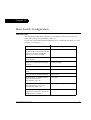
Chapter 10 Basic Switch Configuration ............................................................................ 53
Introduction ...................................................................................................... 53
System Parameter Configuration .................................................................. 54
Identifying the system ......................................................................... 54
Operating parameters .......................................................................... 54
Network Time Acquiring Protocols Parameter Configuration................. 55
Chapter 11 Avaya P330 Layer 2 Features ......................................................................... 57
Overview........................................................................................................... 57
Ethernet ............................................................................................................. 57
Fast Ethernet .............................................................................. 58
Gigabit Ethernet ......................................................................... 58
Avaya P333T User’s Guide
iii
Table of Contents
Configuring Ethernet Parameters .......................................................58
Auto-negotiation ........................................................................58
Full-Duplex/Half-Duplex ........................................................58
Speed ...........................................................................................58
Flow Control ...............................................................................59
Priority ........................................................................................59
MAC Address ............................................................................59
CAM Table ..................................................................................60
Ethernet Configuration CLI Commands ...........................................60
Ethernet Implementation in the Avaya PP333T ...............................61
VLAN Configuration ....................................................................................... 62
VLAN Overview ...................................................................................62
VLAN Tagging ......................................................................................63
Multi VLAN Binding ............................................................................63
Ingress VLAN Security ........................................................................64
VLAN CLI Commands ........................................................................65
VLAN Implementation in the Avaya P333T .....................................66
Port Based Network Access Control (PBNAC)............................................ 67
How "Port Based" Authentication Works .........................................67
PBNAC Implementation in the P330 Family ....................................67
Configuring the P330 for PBNAC ......................................................68
PBNAC CLI Commands ......................................................................68
Spanning Tree Protocol ................................................................................... 71
Overview ................................................................................................71
Spanning Tree Protocol ........................................................................71
Spanning Tree per Port ........................................................................71
Rapid Spanning Tree Protocol (RSTP) ...............................................72
About the 802.1w Standard ......................................................72
Port Roles ....................................................................................72
Spanning Tree Implementation in the P330 Family .........................73
Spanning Tree Protocol CLI Commands ...........................................74
MAC Security.................................................................................................... 76
MAC Security Implementation in P330 .............................................76
MAC Security CLI Commands ...........................................................76
LAG .................................................................................................................... 78
LAG Overview ......................................................................................78
LAG CLI Commands ............................................................................78
LAG Implementation in the Avaya P330 Family of Products ........79
Port Redundancy.............................................................................................. 80
Port Redundancy Operation ...............................................................80
Intermodule Port Redundancy ...........................................................81
Port Redundancy CLI Commands .....................................................81
IP Multicast Filtering ....................................................................................... 83
Overview ................................................................................................83
iv
Avaya P333T User’s Guide
Table of Contents
IP Multicast CLI Commands ............................................................... 84
IP Multicast Implementation in the Avaya P333T ........................... 84
Stack Health ...................................................................................................... 85
Overview ................................................................................................ 85
Implementation of Stack Health in the P330 Family ....................... 85
Stack Health CLI Commands ............................................................. 85
Port Classification ............................................................................................ 86
Overview ................................................................................................ 86
Port Classification CLI Commands .................................................... 86
Stack Redundancy ........................................................................................... 87
Chapter 12 Embedded Web Manager ............................................................................... 89
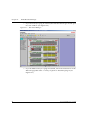
Overview........................................................................................................... 89
System Requirements ...................................................................................... 89
Running the Embedded Web Manager ........................................................ 90
Installing the Java Plug-in............................................................................... 93
Installing from the Avaya P330 Documentation and Utilities
CD ................................................................................................ 93
Install from the Avaya Site ...................................................... 93
Install from your Local Web Site ............................................. 93
Installing the On-Line Help and Java Plug-In on your Web Site.............. 94
Section 4
Troubleshooting and Maintaining the P330
Chapter 14 Troubleshooting the Installation.................................................................... 97
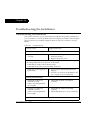
Troubleshooting the Installation.................................................................... 97
Chapter 15 Maintenance...................................................................................................... 99
Introduction ...................................................................................................... 99
Adding/Replacing an Expansion Sub-module ........................................... 99
Adding an Expansion Sub-module to Avaya P330 ......................... 99
Replacing an Existing Expansion Sub-module ................................ 99
Saving Configuration Definitions ......................................... 100
Without Saving Configuration Definitions ......................... 100
Replacing the Stacking Sub-module ........................................................... 100
Chapter 16 Updating the Software .................................................................................. 101
Software Download ....................................................................................... 101
Obtain Software Online ..................................................................... 101
Downloading Software ...................................................................... 101
Download New Version without Overwriting Existing Version ........... 102
How to Contact Us ..................................................................................................................... 103
In the United States ............................................................................ 103
In the AP (Asia Pacific) Region ......................................................... 105
Avaya P333T User’s Guide
v
Table of Contents
In the CALA (Caribbean and Latin America) Region ...................105
vi
Avaya P333T User’s Guide
Preface
Before you Install the P333T
Safety Information
Caution: The Avaya P330 switch and modules contain components sensitive to
electrostatic discharge. Do not touch the circuit boards unless instructed to do so.
Caution: Do not leave any slots open. Cover empty slots using the blanking plates
supplied.
Warning: The fans are on whenever the power is on in the chassis.
FCC Notice
This equipment has been tested and found to comply with the limits for a Class A
digital device, pursuant to part 15 of the FCC Rules. These limits are designed to
provide reasonable protection against harmful interference when the equipment is
operated in a commercial environment. This equipment generates, uses, and can
radiate radio frequency energy and, if not installed and used in accordance with the
instruction manual, may cause harmful interference to radio communications.
Operation of this equipment in a residential area is likely to cause harmful
interference in which case the user will be required to correct the interference at his
own expense.
Changes or modifications to this equipment not expressly approved by Avaya Inc.
could void the user’s authority to operate the equipment.
Conventions Used in the Documentation
Documentation for this product uses the following conventions to convey
instructions and information:
CLI Conventions
• Mandatory keywords are in the computer bold font.
Avaya P333T User’s Guide
vii
•
•
•
•
•
•
Information displayed on screen is displayed in computer font.
Variables that you supply are in pointed brackets <>.
Optional keywords are in square brackets [].
Alternative but mandatory keywords are grouped in braces {} and separated by
a vertical bar |.
Lists of parameters from which you should choose are enclosed in square
brackets [ ] and separated by a vertical bar |.
If you enter an alphanumeric string of two words or more, enclose the string in
inverted ”commas”.
Notes, Cautions and Warnings
Note: Notes contain helpful information or hints or reference to material in other
documentation.
Caution: You should take care. You could do something that may damage
equipment or result in loss of data.
Warning: This means danger. Failure to follow the instructions or warnings may
result in bodily injury. You should ensure that you are qualified for this task and
have read and understood all the instructions
© 2003 Avaya Inc. All rights reserved. All trademarks identified by the ® or TM are
registered trademarks or trademarks, respectively, of Avaya Inc. All other
trademarks are the property of their respective owners.
viii
Avaya P333T User’s Guide
Avaya
AVAYA P333T
SECTION 1: OVERVIEW OF THE P330
Chapter 1
Avaya P333T Overview
Introduction
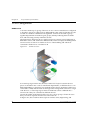
The Avaya P330 family of stackable Ethernet workgroup switches includes a range
of modules with 10/100/1000 Mbps ports, a Layer 3 capability, and ATM and
WAN expansion modules. The Avaya P333T switch has 24 x10/100 Mbps ports and
an Expansion Module slot. The optional expansion modules provide additional
Ethernet, Fast Ethernet, and Gigabit Ethernet connectivity.
An Avaya P330 stack can contain up to 10 switches and up to 3 backup power
supply units. The stacked switches are connected using the Avaya X330STK
stacking Modules which plug into a slot in the back of the Avaya P330. They are
connected using the X330SC or X330LC cable (if the stack is split between two
racks). The Avaya X330RC cable connects the top and bottom switches in the stack
and provides redundancy and hot-swappability in the same way that modules can
be swapped in a modular switching chassis.
The Avaya P330 is fully compliant with IEEE standards for VLAN Tagging, Gigabit
Ethernet, Spanning Tree and Flow Control. This full standards-compliance,
combined with auto-negotiation for 10/100/1000 Mbps and half/full duplex
facilitates the expansion of your network to match your company's growing needs.
Avaya P330 Family Features
•
•
•
•
•
•
•
You can connect up to 10 Avaya P330 switches in a stack. Moreover, this stack
can be either in one rack or split over several racks using the X330LC Long
Cable, according to your requirements.
Avaya X330STK - this stacking Module is used to connect Avaya P330 switches
in a stack, via the Octaplane.
Avaya P330 BUPS - this back-up power supply module supports up to four
Avaya P330 switches.
One RJ-45/RS232 front panel console connector for both terminal and modem
sessions.
Two fan units in every switch, with operation sensors.
One virtual IP address for managing the whole stack, the P330 stack is managed
as a single entity.
Hot-swapping of one switch at a time - by activation of the redundant cable:
— Does not disrupt the operation of other Avaya P330 switches.
— Does not change stack configuration.
— Does not require network downtime.
Avaya P333T User’s Guide
1
Chapter 1
Avaya P333T Overview
•
Connection through Telnet from the front panel ports of any switch, with:
— multiple levels of password protection
— login and inactivity timeouts
Avaya P330 Network Management
Comprehensive network management is a key component of today’s networks.
Therefore we have provided multiple ways of managing the Avaya P330 to suit
your needs.
Avaya P330 Device Manager (Embedded Web)
The built-in Avaya P330 Device Manager (Embedded Web Manager) allows you to
manage an Avaya P330 stack using a Web browser without purchasing additional
software. This application works with the Microsoft® Internet Explorer and
Netscape® Navigator web browsers and Sun Microsystems Java™ Plug-in.
Avaya P330 Command Line Interface (CLI)
The Avaya P330 CLI provides a terminal type configuration tool for local or remote
configuration of Avaya P330 features and functions.
Avaya Multi-Service Network Manager™ (MSNM)
When you need extra control and monitoring or wish to manage other Avaya
network equipment, then the Avaya Multi-Service Network Manager network
management suite is the answer. This suite provides the ease-of-use and features
necessary for optimal network utilization.
Avaya Multi-Service Network Manager is available for Windows® NT®/2000 and
Solaris 8. It can also operate in Stand-Alone mode with Windows® NT®/2000.
Finally, Avaya Multi-Service Network Manager can operate under HP OpenView
for Windows® NT®/2000 and Solaris 8.
Port Mirroring
The P330 provides port mirroring for additional network monitoring functionality.
You can filter the traffic and mirror either incoming traffic to the source port or both
incoming and outgoing traffic. This allows you to monitor the network traffic you
need.
Ports which are members in a Link Aggregation Group (LAG) cannot also be used as
Port Mirroring Destination or Source ports.
2
Avaya P333T User’s Guide
Chapter 1
Avaya P333T Overview
SMON
The P330 supports Avaya’s ground-breaking SMON Switched Network
Monitoring, which the IETF has now adopted as a standard (RFC2613). SMON
provides unprecedented top-down monitoring of switched network traffic at the
following levels:
• Enterprise Monitoring
• Device Monitoring
• VLAN Monitoring
• Port-level Monitoring
This top-down approach gives you rapid troubleshooting and performance
trending to keep the network running optimally.
Note: MSNM Licence is required to run SMON monitoring.
Note: You need to purchase one SMON License per P330 Stack
Fans, Power Supply and BUPS Monitoring
The P330 module has integrated sensors which provide advance warnings of fan
failure, power supply failure or Backup Power Supply (BUPS) failure via
management.
Avaya P333T User’s Guide
3
Chapter 1
4
Avaya P333T Overview
Avaya P333T User’s Guide
Chapter 2
Standards and Compatibility
Avaya P330 Standards Supported
The Avaya P330 complies with the following standards.
IEEE
•
•
•
•
•
•
•
802.3x Flow Control on all ports
802.1Q VLAN Tagging support on all ports
802.1p Priority Tagging compatible on all ports
802.1D Bridges and STA
802.1w Rapid Spanning Tree Protocol
802.1X Port Based Network Access Control
802.3z Gigabit Ethernet on expansion module
•
•
MIB-II - RFC 1213
Structure and identification of management information for TCP/IP-based
Internet - RFC 1155
Simple Network Management Protocol (SNMP) - RFC 1157
PPP Internet Protocol Control Protocol (IPCP) - RFC 1332
PPP Authentication Protocols (PAP & CHAP) - RFC 1334
PPP - RFC 1661
ATM Management - RFC 1695
RMON - RFC 1757
SMON - RFC 2613
Bridge MIB Groups - RFC 2674 dot1dbase and dot1dStp fully implemented.
Support for relevant MIB objects: dot1q (dot1qBase, dot1qVlanCurrent)
The Interfaces Group MIB - RFC 2863
Remote Authentication Dial In User Service (RADIUS) - RFC 2865
IETF - Layer 2
•
•
•
•
•
•
•
•
•
•
IIETF - Network Monitoring
• RMON (RFC 1757) support for groups 1,2,3 and 9
— Statistics
— History
— Alarms
— Events
Avaya P333T User’s Guide
5
Chapter 2
Standards and Compatibility
•
•
6
SMON (RFC 2613) support for groups
— Data Source Capabilities
— Port Copy
— VLAN and Priority Statistics
Bridge MIB Groups - RFC 2674
— dot1dbase and dot1dStp fully implemented.
— Support for relevant MIB objects: dot1q (dot1qBase, dot1qVlanCurrent)
Avaya P333T User’s Guide
Chapter 3
Specifications
Avaya P333T Switch
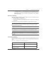
Physical
Height
2U (88 mm, 3.5”)
Width
482.6 mm (19”)
Depth
450 mm (17.7”)
Weight
7.5 kg (16.5 lb)
Power Requirements – AC
Input voltage
100 to 240 VAC, 50/60 Hz
Power dissipation
150 W max
Input current
5.3 A
Power Requirements – DC
Input voltage
-36 to -72 VDC
Power dissipation
150 W max
Input current
5.1 A max
Environmental
Operating Temp.
-5 to 50°C (23 to 122°F)
Relative Humidity
5% to 95% non-condensing
Avaya P333T User’s Guide
7
Chapter 3
Safety
•
•
•
•
UL for US approved according to UL195O Std.
C-UL(UL for Canada) approved according to C22.2 No.950 Std.
CE for Europe approved according to EN 60950 Std.
Laser components are Laser Class I approved:
— EN-60825/IEC-825 for Europe
— FDA CFR 1040 for USA
Safety - AC Version
• Overcurrent Protection: A readily accessible Listed safety-approved protective
device with a 16A rating must be incorporated in series with building
installation AC power wiring for the equipment under protection.
Safety - DC Version
• Restricted Access Area: This unit must be installed in Restricted Access Areas
only.
• Installation Codes: This unit must be installed in accordance with the US
National Electrical Code, Article 110 and the Canadian Electrical Code, Section
12.
• Conductor Ampacity: Per UL 1950, Annex NAE (NEC Article 645-5(a)), the
branch-circuit conductors supply shall have the ampacity of not less than 125
percent of the total connected load. For input leads use at least 18 AWG copper
conductors.
• Overcurrent Protection: Per UL 1950, Annex NAE (NEC Article 240-3), a readily
accessible listed branch-circuit overcurrent protective device rated maximum
10A must be incorporated into the building wiring.
Agency Approvals
EMC Emissions
Approved according to:
• US - FCC Part 15 Subpart B, Class A
• EU - EN55022 Class A
• EU - EN61000-3-2
• Japan - VCCI-A
Immunity
Approved according to:
• EN55024
• EU - EN61000-3-3
8
Avaya P333T User’s Guide
Chapter 3
Other
Approved according to:
• CLEI Code: According to Tecordia (Bellcore) KS-22022 Standard
• NEBS Level 3 (optional mounting brackets)
Interfaces
•
•
24 x 10/100BASE-T RJ45 port connectors.
RS-232 for terminal setup via RJ45 connector on front panel.
•
140,000 hrs minimum
Basic MTBF
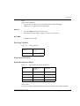
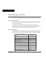
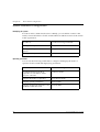
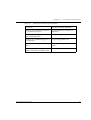
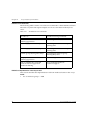
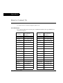
Stacking Module
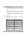
Table A.1
Stacking Module
Number of
Ports
Name
X330STK
2
Expansion Modules
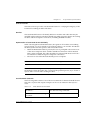
Gigabit Ethernet Expansion Modules
Table A.2
Name
Gigabit Ethernet Expansion Modules
Number of
Ports
Interface
X330S2
2
1000Base-SX
X330L2
2
1000Base-LX
X330S1
1
1000Base-SX
X330L1
1
1000Base-LX
Laser Safety
The Avaya X330S1/S2 multi-mode transceivers and the Avaya X330L1/X330L2
Avaya P333T User’s Guide
9
Chapter 3
single mode transceivers are Class 1 laser products.
They comply with IEC 825-1 and Food and Drug Administration (FDA) 21 CFR
1040.10 and 1040.11.
The transceivers must be operated under recommended operating conditions.
Laser Classification
CLASS 1
LASER PRODUCT
Note: Class 1 lasers are inherently safe under reasonably foreseeable conditions of
operation.
Caution: The use of optical instruments with this product will increase eye hazard.
Usage Restriction
The optical ports of the module must be terminated with an optical connector or a
dust plug when not in use.
Laser Data
Avaya P330S1/2 Expansion Modules
Wavelength: 850 nm
Output power dissipation: Max. 0.63W
Transmit power: Min. -9 dbm, Max. -4 dbm
Receive power: Min. -17 dbm, Max. 0 dbm
Avaya P330L1/2 Expansion Modules
Wavelength: 1300 nm
Output power dissipation: Max. 0.68W
Transmit power (9 µm SMF): Min. -9.5 dbm, Max. -3 dbm
10
Avaya P333T User’s Guide
Chapter 3
Transmit power (62.5 µm and 50 µm MMF): Min. -11.5 dbm, Max. -3 dbm
Receive power (9 µm SMF, 62.5 µm and 50 µm MMF): Min. -20 dbm, Max. -3 dbm
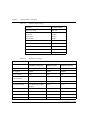
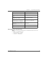
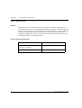
Fast Ethernet Fiber Expansion Module
Table A.3
Name
Fiber Fast Ethernet Expansion Module
Number of
Ports
X330F2
2
Interface
100Base-FX
Ethernet/Fast Ethernet Expansion Module
Table A.4
Name
X330T16
Avaya P333T User’s Guide
Ethernet/Fast Ethernet Expansion Module
Number of
Ports
16
Interface
10/100Base-T
11
Chapter 3
GBIC Expansion Module
The Avaya X330G2 Expansion Module is the GBIC (1.25 Gbit/s Gigabit Ethernet)
Expansion Module for the Avaya P330 family of stackable switches.
Note: In order to use this module the Avaya P330 switch must must have
Embedded S/W Version 2.2 or higher.
The X330G2 can be used either as a Gigabit Ethernet link or as a high Bandwidth
backplane for connecting switches. The introduction of the GBIC interface to the
Avaya P330 family presents an added value over the existing Gigabit Ethernet
expansion modules. You can insert any of the Avaya-authorized GBIC transceivers
into the X330G2 Expansion Module socket. This provides you with a highly
modular and customisable Gigabit Ethernet interface. The GBIC transceivers are
hot-swappable.
Safety Information
The multimode and single-mode GBIC transceivers are Class 1 Laser products.
They comply with EN 60825-1 and Food and Drug Administration (FDA) 21 CFR
1040.10 and 1040.11.
The GBIC transceivers must be operated under recommended operating conditions.
Laser Classification
CLASS 1
LASER PRODUCT
Note: Class 1 lasers are inherently safe under reasonably foreseeable conditions of
operation.
Caution: The use of optical instruments with this product will increase eye hazard.
Usage Restriction
When a GBIC transceiver is inserted into the X330G2 Expansion Module but is not
in use, then the Tx and Rx ports should be protected with an optical connector or a
dust plug.
12
Avaya P333T User’s Guide
Chapter 3
Avaya Approved GBIC Transceivers
Caution: All Avaya approved GBICs are 5V. Do not insert a 3.3V GBIC.
Avaya supplies the following two GBIC transceivers for the Avaya P330 X330G2
Expansion Modules. You can order these directly from your local Avaya
representative using the PEC or COM Codes:
Type
Description
PEC Code
COM Code
GBIC SX
Transceiver
Multimode Fiber
1000BaseSx (550 m)
4705-122
108659228
GBIC LX
Transceiver
Single-mode Fiber
1000BaseLx (10 km)
4705-121
108659210
In addition, Avaya has tested and approved a number of GBIC transceivers from
other manufacturers for use with the Avaya X330G2 Expansion Module.
An up-to-date list can be found in Avaya’s website at the following address:
www.avaya.com/support
Specifications
X330G2- LX GBIC Transceiver
A 9 mm or 10 mm single-mode fiber (SMF) cable may be connected to a
1000Base-LX GBIC port. The maximum length is 10 km (32,808 ft).
A 50 mm or 62.5 mm multimode (MMF) fiber cable may be connected to a 1000BaseLX GBIC port. The maximum length is 550 m (1,804 ft.) for 50 mm and 62.5 mm
cable.
The LX transceiver has a Wavelength of 1300 nm, Transmission Rate of 1.25 Gbps
and Input Power of 5V.
X330G2- SX GBIC Transceiver
A 50 µm or 62.5 µm multimode (MMF) fiber cable may be connected to a 1000BaseSX GBIC port. The maximum length is 500 m (1,640 ft.) for 50 µm cable and 220 m
(722 ft.) for 62.5 µm cable.
The SX transceiver has a Wavelength of 850 nm, Transmission Rate of 1.25 Gbps and
Input Power of 5V.
Avaya P333T User’s Guide
13
Chapter 3
Agency Approval
The transceivers comply with:
• EMC Emission: US – FCC Part 15, Subpart B, Class A;
Europe – EN55022 class A
• Immunity: EN50082-1
• Safety: UL for US UL 1950 Std., C-UL (UL for Canada) C22.2 No.950 Std., Food
and Drug Administration (FDA) 21 CFR 1040.10 and 1040.11, and CE for
Europe EN60950 Std. Complies with EN 60825-1.
MTBF
The Mean Time Between Failures (MTBF) for the X330G2 Expansion Sub-module is
594,639 hours.
X330GT2 Gigabit Ethernet Expansion Module
The X330GT2 Expansion Module provides two copper Gigabit Ethernet 1000Base-T
ports.
Note: The X330GT2 module is only supported by Avaya P330 embedded software
versions 2.4 and higher.
ATM Expansion Modules
There are two Avaya P330 ATM Expansion Modules:
• X330-OC12F1:
500m, Multimode fiber, can also be OC-3 reduced range
• X330-OC12S1:
15 km, Single-mode fiber, can also be OC-3
The ATM Modules can be installed in the following Avaya P330 Family switches:
• Avaya P333T Hardware Version C/S 1.3 and higher, with Embedded S/W 2.4
and higher.
Note: The ATM Expansion Module cannot be used in Avaya P333T hardware
Versions lower than C/S 1.3.
•
•
•
Avaya P334T Embedded S/W Ver. 2.4 and higher.
Avaya P332MF Embedded S/W Ver. 3.0 and higher.
Avaya P333R Embedded S/W Ver. 2.4 and higher.
Refer to the Avaya X330 ATM Access Module Installation Guide for installation
procedures.
The multimode Avaya X330-OC12F1 and X330-OC3F1 (future) ATM Modules are
Class 1 LED products. The single-mode X330-OC12S1 ATM Module is a Class 1
14
Avaya P333T User’s Guide
Chapter 3
Laser product. They comply with EN 60825-1 and Food and Drug Administration
(FDA) 21 CFR 1040.10 and 1040.11.
The Modules must be operated under recommended operating conditions.
Safety Information
Single-mode Module Laser Classification
CLASS 1
LASER PRODUCT
Note: Class 1 lasers are inherently safe under reasonably foreseeable conditions of
operation.
Caution: The use of optical instruments with this product will increase eye hazard.
Multi-Mode Module LED Warning
The following warnings apply to the X330 ATM Modules equipped with multimode fiber.
Class 1
LED Product
Warning: Class 1 LED Product. Do not view the LED through any magnifying
device while it is powered on. Never look directly at the fiber Tx port and fiber cable
ends when powered on.
WAN Expansion Modules
Avaya X330WAN is a series of WAN Edge Router expansion modules for the P330
Stackable Switching System . X330WAN enables you to connect your Avaya P330
switch to a WAN. X330WAN is part of Avaya’s Converged Networks Solution that
includes IP telephones, data switches and IP exchanges.
The X330WAN family includes the following modules:
• X330W-2DS1 access router module has 2 E1/T1 interfaces, a single 10/
Avaya P333T User’s Guide
15
Chapter 3
•
100Base-T Fast Ethernet port, and a Console port.
The X330W-2USP contains 2 USP (Universal Serial Ports), one 10/100Base-T
Fast Ethernet port and one Console port.
An Avaya P330 stack can have X330WAN access router modules inserted in each of
the switches in the stack with an expansion slot. A maximum stack configuration of
10 P334T switches using the X330WAN provides 490 Fast Ethernet 10/100 ports,
and 20 E1/T1 or USP ports.
16
Avaya P333T User’s Guide
Avaya
AVAYA P333T
SECTION 2: INSTALLING THE P330
Chapter 4
Installation
This chapter describes the basic hardware Installation procedures for the Avaya
P330.
Required Tools
Make sure you have the following tools at hand before undertaking the Installation
procedures:
• Philips (cross-blade) screwdriver
Site Preparation
Avaya P330 can be mounted alone or in a stack in a standard 19-inch equipment
rack in a wiring closet or equipment room. Up to 10 units can be stacked in this way.
When deciding where to position the unit, ensure that:
• It is accessible and cables can be connected easily and according to the
configuration rule.
• Cabling is away from sources of electrical noise such as radio transmitters,
broadcast amplifiers, power lines and fluorescent lighting fixtures.
• Water or moisture cannot enter the case of the unit.
• There is a free flow of air around the unit and that the vents in the sides of the
case are not blocked.
Note: Use Octaplane cables to interconnect with other switches.
•
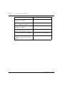
The environmental conditions match the requirements listed below:
Table 4.1
Environmental Prerequisites
Operating Temp.
-5 to 50°C (23 to 122°F)
Relative Humidity
5% to 95% non-condensing
•
The power source matches the specifications listed below:
Table 4.2
Power Requirements – AC
Input voltage
Avaya P333T User’s Guide
100 to 240 VAC, 50/60 Hz
19
Chapter 4
Installation
Power dissipation
150 W max
Input current
5.3 A
Table 4.3
20
Power Requirements – DC
Input voltage
-36 to -72 VDC
Power dissipation
150 W max
Input current
5.1 A max
Avaya P333T User’s Guide
Chapter 4
Installation
Rack Mounting (Optional)
The Avaya P330 case fits in most standard 19-inch racks. Avaya P330 is 2U (88mm,
3.5”) high.
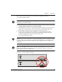
Place the Avaya P330 in the rack as follows:
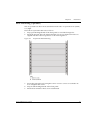
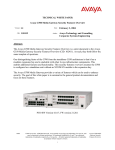
1 Snap open the hinged ends of the front panel to reveal the fixing holes.
2 Insert the unit into the rack. Ensure that the four Avaya P330 screw holes are
aligned with the rack hole positions as shown in Figure 4.1.
Figure 4.1
3
4
5
Avaya P330 Rack Mounting
Secure the unit in the rack using the screws. Use two screws on each side. Do
not overtighten the screws.
Snap closed the hinged ends of the front panel.
Ensure that ventilation holes are not obstructed.
Avaya P333T User’s Guide
21
Chapter 4
Installation
Stacking Switches (Optional)
Avaya P330 is a stackable switching system. Stacking involves the mounting and
connecting of stacking sub-modules in the P330 switch.
Installing the X330STK Stacking Sub-module in the P330
Caution: The stacking sub-modules contain components sensitive to electrostatic
discharge. Do not touch the circuit board unless instructed to do so.
To install the stacking sub-module in the Avaya P330:
1 Remove the blanking plate from the back of the Avaya P330 switch.
2 Insert the stacking sub-module gently into the slot, ensuring that the metal base
plate is aligned with the guide rails.
The metal plate of the X330STK (and not the PCB) fits onto the guide rails.
3 Press the sub-module in firmly until it is completely inserted into the
Avaya P330.
4 Gently tighten the two screws on the side panel of the stacking sub-module by
turning them.
Note: The Avaya P330 switch must not be operated with the back-slot open; the
stacking sub-module should be covered with the supplied blanking plate if necessary.
Connecting Stacking Sub-modules
Before attempting to connect stacking sub-modules, verify that you have the
required Octaplane cables.
Note: The two ends of the Octaplane cable terminate with different connectors. Each
connector can only be connected to its matching port.
The following cables are used to connect stacked switches:
• Short Octaplane cable (X330SC) – ivory-colored, used to connect adjacent
switches (Catalog No. CB0223) or switches separated by a BUPS unit.
• Long/Extra Long Octaplane cable (X330LC/X330L-LC) – ivory-colored, used to
connect switches from two different physical stacks, or switches separated by a
BUPS unit (Catalog No. CB0225/CB0270).
• Redundant/Long Redundant Octaplane cable (X330RC/X330L-RC) – black,
used to connect the top and bottom switches of a stack (Catalog No. CB0222/
CB0269).
22
Avaya P333T User’s Guide
Chapter 4
Installation
These are the same cables that are used with all P330 family modules.
To connect stacked switches:
Note: When adding a module to an existing stack, first connect the stacking cables
and then power up the module.
1
2
3
4
5
Plug the light grey connector of the Short Octaplane cable into the port marked
“to upper unit” of the bottom Avaya P330 switch.
Plug dark grey connector of same Short Octaplane cable to the port marked “to
lower unit” in the unit above. The connections are illustrated in Figure 4.3.
Repeat Steps 1 and 2 until you reach the top switch in the stack.
If you wish to implement stack redundancy, use the Redundant Cable to
connect the port marked “to lower unit” on the bottom switch to the port
marked “to upper unit” on the top switch of the stack.
Power up the added modules.
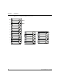
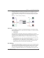
Caution: Do not cross-connect two Avaya P330 switches with two Octaplane (lightcolored) cables. If you wish to cross-connect for redundancy, use one light-colored
Octaplane cable and one black redundancy cable. Figure 4.2 shows an incorrect
connection.
Note: You can build a stack of up to 10 Avaya P330 switches. If you do not wish to
stack all the switches in a single rack, use long Octaplane cables to connect two
physical stacks as shown in Figure 4.3.
Figure 4.2
Incorrect Stack Connection
BUPS
Connector
Cable to
Lower Unit
Cable to
Upper Unit
Cable to
Lower Unit
Cable to
Upper Unit
Power Supply
Connector
BUPS
Connector
Power Supply
Connector
Avaya P333T User’s Guide
23
Chapter 4
Installation
Figure 4.3
Avaya P330 Stack Connections
BUPS
Connector
BUPS
Connector
Cable to
Lower Unit
Cable to
Upper Unit
5
Power Supply
Connector
X330SC
BUPS
Connector
Cable to
Lower Unit
Cable to
Upper Unit
Cable to
Upper Unit
10
Cable to
Lower Unit
Cable to
Upper Unit
9
Cable to
Lower Unit
Cable to
Upper Unit
Cable to
Lower Unit
Cable to
Upper Unit
Cable to
Lower Unit
Cable to
Upper Unit
BUPS
Connector
4
Power Supply
Connector
Power Supply
Connector
BUPS
Connector
BUPS
Connector
Cable to
Lower Unit
Cable to
Upper Unit
3
Power Supply
Connector
8
Power Supply
Connector
BUPS
Connector
BUPS
Connector
Cable to
Lower Unit
Cable to
Upper Unit
2
Power Supply
Connector
Power Supply
Connector
BUPS
Connector
BUPS
Connector
X330RC
Power Supply
Connector
Cable to
Lower Unit
Power Supply
Connector
Cable to
Lower Unit
Cable to
Upper Unit
1
7
6
Power Supply
Connector
X330LC
24
Avaya P333T User’s Guide
Chapter 4
Installation
Installing Expansion Sub-modules
Caution: The expansion sub-modules contain components sensitive to electrostatic
discharge. Do not touch the circuit board unless instructed to do so.
Installing the Expansion Sub-module into the Avaya P330
1 Remove the blanking plate or other sub-module (if installed).
2 Insert the sub-module gently into the slot, ensuring that the Printed Circuit
Board (PCB) is aligned with the guide rails.
The PCB not the metal base plate fits into the guide rail.
3 Firmly press the sub-module until it is completely inserted into the Avaya P330.
4 Gently tighten the two screws on the front panel of the expansion sub-module
by turning them.
Note: The Avaya P330 switch must not be operated with the expansion slot open;
the expansion sub-module slot should be covered with the supplied blanking plate
if necessary.
Avaya P333T User’s Guide
25
Chapter 4
Installation
Making Connections to Network Equipment
This section describes the physical connections that you can make between the
Avaya P330 switch and other network equipment.
Prerequisites
Make sure you have the following before attempting to connect network equipment
to the P330 switch:
• a list of network equipment to be connected to the P330 switch, detailing the
connector types on the various units
• all required cables (see below). Appropriate cables are available from your local
supplier.
Port Types
Avaya P330 supports the following types of ports (according to the speed and
standard they support):
• LAN — 10/100Base-T, 100Base-FX, 1000Base-T 1000Base-SX and 1000Base-LX
• WAN — by type:
— X330W-2DS1: E1/T1, 10/100Base-T
— X330W-2USP: USP (V.35), 10/100Base-T
Note: To interconnect Avaya P330 switches with twisted pairs, crossed cables are
required.
•
•
•
•
26
The maximum UTP cable length connected to a 10/100 Mbps port operating as
10Base-T, is 100 m (328 ft.).
A UTP Category 5 cable must be connected to any 100Base-TX port, via an RJ45
connector. The maximum UTP cable length connected to a 10/100 Mbps port
operating as 100Base-TX, is 100 m (328 ft.).
A fiberoptic cable must be connected to any 100Base-FX port, via a SC
connectors. The maximum fiber cable length connected to a 100Base-FX port is
412 m (1,352 ft) when operating in half duplex, and 2 km (6,562 ft) when
operating in full duplex.
A fiberoptic cable must be connected to 1000Base-SX or 1000Base-LX port, via
SC connectors, according to the table below.
Avaya P333T User’s Guide
Chapter 4
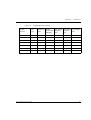
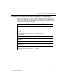
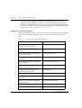
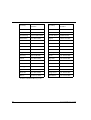
Table 4.4
Installation
Gigabit Ethernet Cabling
Gigabit
Interface
Fiber
Type
Diameter
(µm)
Modal
Bandwidth
(MhzKm)
Maximum
Distance
(m)
Minimum
Wavelength
Distance
(nm)
(m)
1000BASE-SX
MM
62.5
160
220
2
850
1000BASE-SX
MM
62.5
200
275
2
850
1000BASE-SX
MM
50
400
500
2
850
1000BASE-SX
MM
50
500
550
2
850
1000BASE-LX
MM
62.5
500
550
2
1310
1000BASE-LX
MM
50
400
550
2
1310
1000BASE-LX
SM
9
NA
10,000
2
1310
Avaya P333T User’s Guide
27
Chapter 4
28
Installation
Avaya P333T User’s Guide
Chapter 5
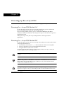
Powering Up the Avaya P330
This section describes the procedures for powering up the Avaya P330 unit.
Powering On – Avaya P330 Module AC
For the AC input version of the Avaya P330, insert the AC power cord into the
power inlet in the back of the unit. The unit powers up.
If you are using a BUPS, insert a power cord from the BUPS into the BUPS
connector in the back of the unit. The unit powers up even if no direct AC power is
applied to the unit.
After power up or reset, the Avaya P330 performs a self test procedure.
applied to it.
Powering On – Avaya P330 Module DC
For the DC input version of the Avaya P330, connect the power cable to the switch
at the input terminal block.
1 The terminals are marked “+”, “-“ and with the IEC 5019a Ground symbol.
2 The size of the three screws in the terminal block is M3.5.
3 The pitch between each screw is 9.5mm.
Connect the power cable to the DC power supply. After power up or reset, the
Avaya P330 performs a self test procedure.
Warning: Before performing any of the following procedures, ensure that DC power
is OFF.
Caution: This product is intended for installation in restricted access areas and is
approved for use with 18 AWG copper conductors only. The installation must
comply with all applicable codes.
Warning: The proper wiring sequence is ground to ground, positive to positive and
negative to negative. Always connect the ground wire first and disconnect it last.
Avaya P333T User’s Guide
29
Chapter 5
Powering Up the Avaya P330
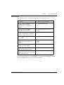
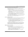
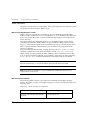
Post-Installation
The following indicate that you have performed the installation procedure
correctly:
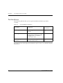
Table 5.1
Post-Installation Indications
Troubleshooting
Information
Procedure
Indication
Powering the P330
All front panel LEDs illuminate
briefly
Page 97
Creating Stacks
The LED next to the
appropriate connection (“Cable
to upper unit” or “Cable to
lower unit”) is lit.
Page 97
Installing Expansion
Modules
The LEDs on the Expansion
Module flash briefly.
Page 97
If you do not receive the appropriate indication, please refer to "Troubleshooting the
Installation".
30
Avaya P333T User’s Guide
Chapter 6
Avaya P333T Front and Back Panels
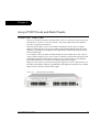
Avaya P333T Front Panel
The Avaya P333T front panel contains LEDs, controls, connectors and an expansion
Module slot, as well as a console connector. The status LEDs and control buttons
provide at-a-glance information.
The front panel LEDs consist of Port LEDs and Function LEDs. The Port LEDs
display information for each port according to the illuminated function LED. The
function is selected by pressing the left or right button until the desired parameter
LED is illuminated.
For example, if the COL LED is illuminated, then all Port LEDs show the collision
status of their respective port. If you wish to select the LAG function, then press the
right button until the LAG Function LED is lit; if you then wish to select Rx then
press the left button several times until the Rx function LED lights.
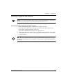
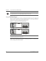
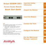
Figure 6.1 shows the Avaya P333T front panel. Figure 6.2 shows a detailed view of
the LEDs (described in Table 6.1), pushbuttons, the Expansion Module slot, and the
RJ-45 console connector at the bottom right.
Figure 6.1
Avaya P333T User’s Guide
Avaya P333T Front Panel
31
Chapter 6
Avaya P333T Front and Back Panels
Figure 6.2
Avaya P333T LEDs
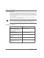
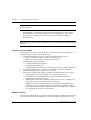
Note: All LEDs are lit during a reset.
Table 6.1
LED Name
Avaya P333T LED Descriptions
Description
LED Status
OFF – power is off
PWR
Power status
ON – power is on
Blink – using BUPS only
OPR
CPU operation
OFF – Module is booting
ON – Normal operation
OFF – Module is a slave in a stack
SYS
System Status
ON – Module is the Master of the stack and
the Octaplane and Redundant cable are
connected correctly.
This LED will also light in Standalone mode.
Blink – Box is the stack Master and the stack
is in redundant mode.
The following Function LEDs apply to ports 1 to 66
OFF – Port disabled
LNK
Port status
ON – Port enabled and link OK
Blink – Port enabled and the link is down
32
Avaya P333T User’s Guide
Chapter 6
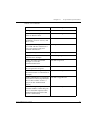
Table 6.1
Avaya P333T Front and Back Panels
Avaya P333T LED Descriptions
LED Name
Description
COL
Collision
LED Status
OFF – No collision or FDX port
ON – Collision occurred on line
OFF – No transmit activity
Tx
Transmit to line
ON – Data transmitted on line from the
module
OFF – No receive activity
Rx
Receive from line
FDX
Half/Full Duplex
ON – Data received from the line into the
module
OFF – Half duplex mode
ON – Full duplex mode
OFF – No Flow Control
FC
Flow Control
Hspd
High Speed
ON – Symmetric/Asymmetric Flow Control
mode is enabled and port is in full duplex
mode.
OFF:
ON:
Link Aggregation
Group (Trunking)
LAG
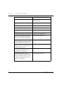
Table 6.2
10/100
10
100
1000
N/A
1000
OFF – No LAG defined for this port
ON – Port belongs to a LAG
Avaya P330 <- -> Select buttons
Description
Function
Left/Right
Individual – select LED function (see table above).
Reset module
Press both right and left buttons together for approximately two
seconds. All LEDs on module light up until buttons are
released.
Reset stack
Press both right and left buttons together for 4 seconds. All
LEDs on stack light up until buttons are released.
FIV
Not in use.
Avaya P333T User’s Guide
33
Chapter 6
Avaya P333T Front and Back Panels
Note: The Port LEDs of the P333T are numbered from 1-24. Expansion Module ports
are numbered from 51. Port LED numbers 49-50 are reserved.
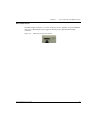
Avaya P330 Back Panel
The Avaya P330 back panel contains a stacking sub-module slot, power supply and
BUPS connector. Figure 6.3 shows the back panel of the AC switch (top) and the DC
switch (bottom) with a stacking sub-module installed.
Figure 6.3
Avaya P330 AC and DC Back Panels
Note: Further illustrations of the Avaya P330 Back Panel will be that of the AC
model, the topmost panel in Figure 6.3.
Figure 6.3 shows the back panel of the AC switch (top) and the DC switch (bottom)
with a stacking sub-module installed.
34
Avaya P333T User’s Guide
Chapter 6
Avaya P333T Front and Back Panels
BUPS Input Connector
The BUPS input connector is a 5 VDC connector for use with the Avaya P330 BUPS
unit only. A BUPS Input sticker appears directly to the right the BUPS input
connector.
Figure 6.4
Avaya P333T User’s Guide
BUPS Input Connector Sticker
35
Chapter 6
36
Avaya P333T Front and Back Panels
Avaya P333T User’s Guide
Chapter 7
Establishing Switch Access
This chapter describes various methods for accessing the Avaya P330 CLI,
including:
• a terminal to the serial port on the switch
• P330 Sessions
• a workstation running a Telnet session connected via the network
• a remote terminal/workstation attached via a modem (PPP connection)
Establishing a Serial Connection
This section describes the procedure for establishing switch access between a
terminal and the Avaya P330 switch over the serial port provided on the front panel
of the P330 (RJ-45 connector labeled "Console").
Configuring the Terminal Serial Port Parameters
The serial port settings for using a terminal or terminal emulator are as follows:
• Baud Rate - 9600 bps
• Data Bits - 8 bits
• Parity - None
• Stop Bit - 1
• Flow Control - None
• Terminal Emulation - VT-100
Connecting a Terminal to the Avaya P330 Serial port
Perform the following steps to connect a terminal to the Avaya P330 Switch
Console port for acessing the text-based CLI:
1 The P330 device is supplied with a console cable and a RJ-45-to-DB-9 adaptor.
Use these items to connect the serial (COM) port on your PC/terminal to the
Avaya P330 console port.
2 Ensure that the serial port settings on the terminal are 9600 baud, 8 bits, 1 stop
bit and no parity.
3 When you are prompted for a Login Name, enter the default login. The default
login is root.
4 When you are promoted for a password, enter the user level password root.
5 Now you can begin the configuration of Module or Stack parameters.
Avaya P333T User’s Guide
37
Chapter 7
Establishing Switch Access
P330 Sessions
You can use sessions to switch between the CLI of P330 modules / other stack
entities (for example, an X330 ATM or WAN entity plugged into a specific P330
switch or with the G700 Media Gateway Precessor) or to switch between Layer 2
and Layer 3 commands in the router module.
To switch between P330 modules use the command:
session [<mod_num>] <mode>.
The <mod_num> is the number of the module in the stack, counting from the bottom
up.
The <mode> can be either switch, router, wan, atm, mgp.
Use switch mode to configure layer 2 commands.
Use router mode to configure routing commands.
Examples:
To configure router parameters in the module that you are currently logged into,
type the following command:
session router.
To configure the switch parameters, on module 6, type the command:
session 6 switch.
Note: When you use the session command the security level stays the same.
Assigning P330’s IP Stack Address
Note: All P330 switches are shipped with the same default IP address. You must
change the IP address of the master P330 switch in a stack in order to guarantee that
the stack has its own unique IP address in the network.
The network management station or a workstaion running Telnet session can
establish communications with the stack once this address had been assigned and
the stack has been inserted into the network. Use the CLI to assign the P330 stack an
IP address and net mask.
To assign a P330 IP stack address:
1 Establish a serial connection by connecting a terminal to the Master P330 switch
of the stack.
2 When prompted for a Login Name, enter the default name root
3 When you are prompted for a password, enter the password root. You are
now in Supervisor Level.
38
Avaya P333T User’s Guide
Chapter 7
4
5
6
7
8
Establishing Switch Access
At the prompt, type:
set interface inband <vlan> <ip_address> <netmask>
Replace <vlan>, <ip_address> and <netmask> with the VLAN,
IP address and net mask of the stack.
Press Enter to save the IP address and net mask.
At the prompt, type reset and press Enter to reset the stack. After the Reset,
log in again as described above.
At the prompt, type set ip route <dest> <gateway> and replace <dest>
and <gateway> with the destination and gateway IP addresses.
Press Enter to save the destination and gateway IP addresses.
Establishing a Telnet Connection
Perform the following steps to establish a Telnet connection to the Avaya P330 for
configuration of Stack or Router parameters. You can Telnet the Stack Master IP
address:
1 Connect your station to the network.
2 Verify that you can communicate with the Avaya P330 using Ping to the IP of
the Avaya P330. If there is no response using Ping, check the IP address and
default gateway of both the Avaya P330 and the station.
Note: The Avaya P330 default IP address is 149.49.32.134 and the default subnet
mask is 255.255.255.0.
3
4
5
From the Microsoft Windows® taskbar of your PC click Start and then Run (or
from the DOS prompt of your PC), then start the Telnet session by typing:
telnet <P330_IP_address>
For example: telnet 149.49.32.134
If the IP Address in Telnet command is the IP address of the stack, then
connection is established with the Switch CLI entity of the Master module.
When you see the “Welcome to P330” menu and are prompted for a Login
Name, enter the default name root
When you are prompted for a password, enter the User Level password root
in lower case letters (do NOT use uppercase letters). The User level prompt will
appear when you have established communications with the Avaya P330. You
can now configure the Avaya P330 stack and change its default IP address.
Avaya P333T User’s Guide
39
Chapter 7
Establishing Switch Access
Establishing a Modem (PPP) Connection with the P330
Overview
Point-to-Point Protocol (PPP) provides a Layer 2 method for transporting multiprotocol datagrams over modem links.
Connecting a Modem to the Console Port
A PPP connection with a modem can be established only after the Avaya P330 is
configured with an IP address and net-mask, and the PPP parameters used in the
Avaya P330 are compatible with the modem’s PPP parameters.
1 Connect a terminal to the console port of the Avaya P330 switch as described in
Connecting a Terminal to the Avaya P330 Serial port.
2 When you are prompted for a Login Name, enter the default name root.
3 When you are prompted for a password, enter the password root. You are
now in Supervisor Level.
4 At the prompt, type:
set interface ppp <ip_addr><net-mask>
with an IP address and netmask to be used by the Avaya P330 to connect via its
PPP interface.
Note: The PPP interface configured with the set interface ppp command
must be on a different subnet from the stack inband interface.
5
6
Set the baud rate, ppp authentication, and ppp time out required to match your
modem. These commands are described in the “Command Line Interface”
chapter.
At the prompt, type:
set interface ppp enable
The CLI responds with the following:
Entering the Modem mode within 60 seconds...
7
8
9
40
Please check that the proprietary modem cable is plugged
into the console port
Use the DB-25 to RJ-45 connector to plug the console cable to the modem’s DB25 connector. Plug the other end of the cable RJ-45 connector to the
Avaya P330 console’s RJ-45 port.
The Avaya P330 enters modem mode.
You can now dial into the switch from a remote station, and open a Telnet
session to the PPP interface IP address.
Avaya P333T User’s Guide
Chapter 8
User Authentication
Introduction
A secure system provides safeguards to insure that only authorized personnel can
perform configuration procedures. In Avaya P330, these safeguards form part of
the CLI architecture and conventions.
Security Levels
There are four security access levels – User, Privileged, Configure and Supervisor.
• The User level (‘read-only’) is a general access level used to show system
parameter values.
• The Privileged level (‘read-write’) is used by site personnel to access stack
configuration options.
• The Configure level is used by site personnel for Layer 3 configuration.
• (Note: This is not applicable to Avaya P333-T.)
• The Supervisor level (‘administrator’) is used to define user names, passwords,
and access levels of up to 10 local users. In Supervisor level you can also access
RADIUS authentication configuration commands.
Note: If you wish to define more than ten users per switch, or accounts for a user on
multiple switches, you should use RADIUS (Remote Authentication Dial-In User
Service).
A login name and password are always required to access the CLI and the
commands. The login name, password, and access-type (i.e., security level) for a
user account are established using the username command.
Switching between the entities, does not effect the security level since security levels
are established specifically for each user. For example, if the operator with a
privileged security level in the Switch entity switches to the Router entity the
privileged security level is retained.
Note: If you wish to increase security, you can change the default user accounts and
SNMP communities.
Avaya P333T User’s Guide
41
Chapter 8
User Authentication
Note: The Web management passwords are the same as those of the CLI. If you
change the passwords of the CLI then those passwords become active for Web
management as well.
Entering the Supervisor Level
The Supervisor level is the level in which you first enter P330 CLI and establish user
names for up to 10 local users. When you enter the Supervisor level, you are asked
for a Login name. Type root as the Login name and the default password root
(in lowercase letters):
Welcome to P330
Login: root
Password:****
Password accepted.
Cajun_P330-N(super)#
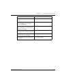
Defining new local users
Define new users and access levels using the following command in Supervisor
Level.
In order to...
Use the following command...
Add a local user account and
configure a user (name, password
and access level)
username
To remove a local user account
no username
Display the username, password
and access type for all users on the
switch
show username
Exiting the Supervisor Level
To exit the Supervisor level, type the command exit.
42
Avaya P333T User’s Guide
Chapter 8
User Authentication
Entering the CLI
To enter the CLI, enter your username and password. Your access level is indicated
in the prompt as follows:
The User level prompt is shown below:
Cajun_P330-N>
The Privileged level prompt is shown below:
Cajun_P330-N#
The Configure level prompt for Layer 3 configuration is shown below:
P330-N(configure)#
The Supervisor level prompt is shown below:
Cajun_P330-N(super)#
RADIUS
Introduction to RADIUS
User accounts are typically maintained locally on the switch. Therefore, if a site
contains multiple Avaya Switches, it is necessary to configure each switch with its
own user accounts. Additionally, if for example a 'read-write' user has to be
changed into a 'read-only' user, you must change all the 'read-write' passwords
configured locally in every switch, in order to prevent him from accessing this level.
This is obviously not effective management. A better solution is to have all of the
user login information kept in a central location where all the switches can access it.
P330 features such a solution: the Remote Authentication Dial-In User Service
(RADIUS).
A RADIUS authentication server is installed on a central computer at the customer's
site. On this server user authentication (account) information is configured that
provides various degrees of access to the switch. The P330 will run as a RADIUS
client. When a user attempts to log into the switch, if there is no local user account
for the entered user name and password, then the switch will send an
Authentication Request to the RADIUS server in an attempt to authenticate the user
remotely. If the user name and password are authenticated, then the RADIUS server
responds to the switch with an Authentication Acknowledgement that includes
information on the user's privileges ('administrator', 'read-write', or 'read-only'),
and the user is allowed to gain access to the switch. If the user is not authenticated,
then an Authentication Reject is sent to the switch and the user is not allowed access
to the switch's embedded management.
The Remote Authentication Dial-In User Service (RADIUS) is an IETF standard
(RFC 2138) client/server security protocol. Security and login information is stored
in a central location known as the RADIUS server. RADIUS clients such as the P330,
communicate with the RADIUS server to authenticate users.
Avaya P333T User’s Guide
43
Chapter 8
User Authentication
All transactions between the RADIUS client and server are authenticated through
the use of a “shared secret” which is not sent over the network. The shared secret is
an authentication password configured on both the RADIUS client and its RADIUS
servers. The shared secret is stored as clear text in the client’s file on the RADIUS
server, and in the non-volatile memory of the P330. In addition, user passwords are
sent between the client and server are encrypted for increased security.
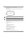
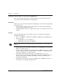
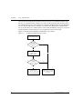
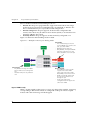
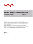
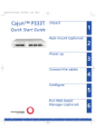
Figure 8.1 illustrates the RADIUS authentication procedure:
Figure 8.1
RADIUS Authentication Procedure
User attempts login
Local User
account
authenticated in
switch?
No
Authentication
request sent to
RADIUS Server
User name and
password
authenticated?
Yes
Yes
No
Authentication Reject
sent to switch
User cannot access switch
embedded managegment
44
Perform log-in according
to user's priviliege level
to switch
Avaya P333T User’s Guide
Chapter 8
User Authentication
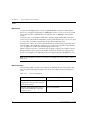
Radius Commands
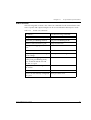
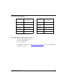
The following radius commands are accessible from Supervisor level.
In order to...
Use the following command...
Enable or disable authentication for
the P330 switch. RADIUS
authentication is disabled by
default
set radius authentication
Set a primary or secondary
RADIUS server IP address
set radius authentication server
Configure a character string to be
used as a “shared secret” between
the switch and the RADIUS server.
set radius authentication secret
Set the RFC 2138 approved UDP
port number.
set radius authentication udp-port
Set the number of times an access
request is sent when there is no
response
set radius authentication retrynumber
Set the time to wait before resending an access request.
set radius authentication retry-time
Remove a primary or secondary
RADIUS authentication server
clear radius authentication server
Display all RADIUS authentication
configurations. The shared secrets
will not be displayed
show radius authentication
For a complete description of the RADIUS CLI commands, including syntax and
output examples, refer to Avaya P330: Reference Guide.
Avaya P333T User’s Guide
45
Chapter 8
User Authentication
Allowed Managers
With the Allowed Managers feature, the network manager can determine who may
or may not gain management access to the switch. The feature can be enabled or
disabled (default is disabled). When enabled, only those users that are configured in
the Allowed Managers table are able to gain Telnet, HTTP, and SNMP management
access to the switch.
You can configure up to 20 Allowed Mangers by adding or removing their IP
address from the Allowed Managers List.
Note: The identification of an “Allowed Manager” is done by checking the Source IP
address of the packets, thus if the Source IP address is modified on the way (NAT,
Proxy, etc.), even an “Allowed Manager” will not be able to access the P330.
Allowed Manager CLI Commands
46
In order to...
Use the following command...
When set to enabled - only
managers with ip address specified
in the allowed table will be able to
access the device
set allowed managers
Add/delete ip address of manager
to/from the allowed table
set allowed managers ip
Show the IP addresses of the
managers that are allowed to access
the device
show allowed managers table
Show whether the status of allowed
managers is enabled or disabled
show allowed managers status
Show the IP addresses of the
managers that are currently
connected
show secure current
Avaya P333T User’s Guide
Avaya
AVAYA P333T
SECTION 3: CONFIGURATION OF THE P330
Chapter 9
Default Settings of the P330
This section describes the procedures for the first-time configuration of the Avaya
P330. The factory defaults are set out in detail in the tables included in this chapter.
Configuring the Switch
The Avaya P330 may be configured using the text-based Command Line Interface
(CLI), the built-in Avaya P330 Device Manager (Embedded Web) or Avaya MultiService Network Manager™.
For instructions on the text-based CLI, see the Avaya P330 Reference Guide.
For instructions on installation of the graphical user interfaces, see Embedded Web
Manager. For instructions on the use of the graphical user interfaces, refer to the
Device Manager User’s Guide on the Documentation and Utilities CD.
Avaya P330 Default Settings
The default settings for the Avaya P330 switch and its ports are determined by the
Avaya P330 software. These default settings are subject to change in newer versions
of the Avaya P330 software. See the Release Notes for the most up-to-date settings.
Table 9.1
Default Switch Settings
Function
Default Setting
IP address
149.49.32.134
Subnet Mask
255.255.255.0
Default gateway
0.0.0.0
Management VLAN ID
1
Spanning tree
Enabled
Bridge priority for Spanning Tree
32768
Keep alive frame transmission
Enabled
Network time acquisition
Enabled, Time
protocol
Time server IP address
0.0.0.0
Avaya P333T User’s Guide
49
Chapter 9
Default Settings of the P330
Table 9.1
Default Switch Settings
Function
Default Setting
Timezone offset
0 hours
SNMP communities:
Read-only
Read-write
Trap SNMP
Public
Public
Public
SNMP retries number
3
SNMP timeout
2000 Seconds
SNMP authentication trap
Disabled
CLI timeout
15 Minutes
User Name/Password
root/root
Table 9.2
Default Port Settings
Function
Default Setting
10/100Base-TX ports
100Base-F ports
1000 Base-X ports
Duplex mode
Full duplex
Full duplex
Full duplex only
Port Speed
100M
100M
1000M
Flow control
Off
Off
Off
Flow control
advertisement
Off
N/A
Off (No pause)
Backpressure
On (only in Half duplex)
Not Applicable
Not Applicable
Autopartitioning
Disabled (only in Half
duplex)
N/A
N/A
Auto-negotiation
Enable
Not Applicable
Enable1
Administration status
Enable
Enable
Enable
Port VLAN
1
1
1
Tagging mode
Clear
Clear
Clear
50
Avaya P333T User’s Guide
Chapter 9
Table 9.2
Default Port Settings
Function
1
Default Settings of the P330
Default Setting
Port priority
0
0
0
Spanning Tree cost
20
20
4
Spanning Tree port
priority
128
128
128
Ensure that the other side is also set to Autonegotiation Enabled
Note: Functions operate in their default settings unless configured otherwise.
Avaya P333T User’s Guide
51
Chapter 9
52
Default Settings of the P330
Avaya P333T User’s Guide
Chapter 10
Basic Switch Configuration
Introduction
This chapter describes the parameters you can define for the chassis, such as its
name and location, time parameters, and so on.
Use the CLI commands briefly described below for configuring the display on your
terminal or workstation.
In order to...
Use the following command...
Open a CLI session to a P330
module in the stack, ATM or WAN
expansion modules and Media
Gateway Processor of G700.
session
Display or set the terminal width
(in characters)
terminal width
Display or set the terminal length
(in lines)
terminal length
Display or set the prompt
hostname
Return the prompt to its default
value
no hostname
Clear the current terminal display
clear screen
Set the number of minutes before
an inactive CLI session
automatically logs out
set logout
Display the number of minutes
before an inactive CLI session
automatically times out
show logout
Access Layer 3 configuration if not
logged in as supervisor (see “User
Authentication“ chapter)
configure
Avaya P333T User’s Guide
53
Chapter 10
Basic Switch Configuration
System Parameter Configuration
Identifying the system
In order to make a P330 switch easier to identify, you can define a name for the
switch, contact information for the switch technician and the location of the switch
in the organization.
In order to...
Use the following command...
Configure the system name.
set system name
Configure the system contact
person
set system contact
Configure the system location
set system location
Operating parameters
You can use the following commands to configure and display the mode of
operation for the switch and display key parameters.
54
In order to...
Use the following command...
Configure the basic mode of
operation of a module to either
Layer 2 or Router
set device-mode
Display the mode of operation
show device-mode
Display system parameters
show system
Display module information for all
modules within the stack
show module
Avaya P333T User’s Guide
Chapter 10
Basic Switch Configuration
Network Time Acquiring Protocols Parameter Configuration
The P330 can acquire the time form a Network Time Server. P330 supports the
SNTP Protocol (RFC 958) over UDP port 123 or TIME protocol over UDP port 37.
Use the CLI commands briefly described below for configuring and display time
information and acquiring parameters.
In order to...
Use the following command...
Restore the time zone to its default,
UTC.
clear timezone
Configure the time zone for the
system
set timezone
Configure the time protocol for use
in the system
set time protocol
Enable or disable the time client
set time client
Configure the network time server
IP address
set time server
Display the current time
show time
Display the time status and
parameters
show time parameters
Display the current time zone offset
show timezone
Get the time from the time server
get time
Avaya P333T User’s Guide
55
Chapter 10
56
Basic Switch Configuration
Avaya P333T User’s Guide
Chapter 11
Avaya P330 Layer 2 Features
This section describes the Avaya P330 Layer 2 features. It provides the basic
procedures for configuring the P330 for Layer 2 operation.
Overview
The P330 family supports a range of Layer 2 features. Each feature has CLI
commands associated with it. These commands are used to configure, operate, or
monitor switch activity for each of the Layer 2 features.
This section of the User’s Guide explains each of the features. Specifically, the topics
discussed here include:
• Ethernet
• VLAN
• Port Based Network Access Control
• Spanning Tree Protocol
• Rapid Spanning Tree Protocol
• MAC Security
• Link Aggregation Group (LAG)
• Port Redundancy
• IP Multicast Filtering
• Stack Health
• Stack Redundancy
• Port Classification
Ethernet
Ethernet is one of the most widely implemented LAN standards. It uses the Carrier
Sense Multiple Access with Collision Detection (CSMA/CD) access method to
handle simultaneous demands. CSMA/CD is a multi-user network allocation
procedure in which every station can receive the transmissions of every other
station. Each station waits for the network to be idle before transmitting and each
station can detect collisions by other stations.
The first version of Ethernet supported data transfer rates of 10 Mbps, and is
therefore known as 10BASE-T.
Avaya P333T User’s Guide
57
Chapter 11
Avaya P330 Layer 2 Features
Fast Ethernet
Fast Ethernet is a newer version of Ethernet, supporting data transfer rates of 100
Mbps. Fast Ethernet is sufficiently similar to Ethernet to support the use of most
existing Ethernet applications and network management tools. Fast Ethernet is also
known as 100BASE-T (over copper) or 100BASE-FX (over fiber).
Fast Ethernet is standardized as IEEE 802.3u.
Gigabit Ethernet
Gigabit Ethernet supports data rates of 1 Gbps. It is also known as 1000BASE-T
(over copper) or 1000BASE-FX (over fiber).
Gigabit Ethernet is standardized as IEEE 802.3z.
Configuring Ethernet Parameters
Auto-negotiation
Auto-Negotiation is a protocol that runs between two stations, two switchs or a
station and a switch. When enabled, Auto-Negotiation negotiates port speed and
duplex mode by detecting the highest common denominator port connection for the
endstations. For example, if one workstation supports both 10 Mbps and 100 Mbps
speed ports, while the other workstation only supports 10 Mbps, then AutoNegotiation sets the port speed to 10 Mbps.
For Gigabit ports, Auto-Negotiation determines the Flow Control configuration of
the port.
Full-Duplex/Half-Duplex
Devices that support Full-Duplex can transmit and receive data simultaneously, as
opposed to half-duplex transmission where each device can only communicate in
turn.
Full-Duplex provides higher throughput than half-duplex.
Speed
The IEEE defines three standard speeds for Ethernet: 10, 100 and 1000 Mbps (also
known as Ethernet, Fast Ethernet and Gigabit Ethernet respectively).
58
Avaya P333T User’s Guide
Chapter 11
Avaya P330 Layer 2 Features
Flow Control
The process of adjusting the flow of data from one device to another to ensure that
the receiving device can handle all of the incoming data. This is particularly
important where the sending device is capable of sending data much faster than the
receiving device can receive it.
There are many flow control mechanisms. One of the most common flow control
protocols, used in Ethernet full-duplex, is called xon-xoff. In this case, the receiving
device sends a an xoff message to the sending device when its buffer is full. The
sending device then stops sending data. When the receiving device is ready to
receive more data, it sends an xon signal.
Priority
By its nature, network traffic varies greatly over time, so short-term peak loads may
exceed the switch capacity. When this occurs, the switch must buffer frames until
there is enough capacity to forward them to the appropriate ports.
This, however, can interrupt time-sensitive traffic streams, such as Voice and other
converged applications. These packets need to be forwarded with the minimum of
delay or buffering. In other words, they need to be given high priority over other
types of networkl traffic.
Priority determines in which order packets are sent on the network and is a key part
of QoS (Quality of Service). The IEEE standard for priority on Ethernet networks is
802.1p.
Avaya P330 switches supports two internal priority queues – the High Priority
queue and the Normal Priority queue.
• Packets tagged with priorities 4-7 are mapped to the High Priority queue;
packets tagged with priorities 0-3 are mapped to the Normal Priority queue.
This classification is based either on the packet’s original priority tag, or, if the
packet arrives at the port untagged, based on the priority configured for the
ingress port (set using the set port level CLI command).
In cases where the packet was received tagged, this priority tag is retained when the
packet is transmitted through a tagging port.
In cases where the priority is assigned based on the ingress priority of the port, then
on an egress tagging port the packet will carry either priority 0 or priority 4,
depending on the queue it was assigned to (High Priority=4, Normal Priority=0).
MAC Address
The MAC address is a unique 48-bit value associated with any network adapter.
MAC addresses are also known as hardware addresses or physical addresses. They
uniquely identify an adapter on a LAN.
MAC addresses are 12-digit hexadecimal numbers (48 bits in length). By
convention, MAC addresses are usually written in one of the following two formats:
• MM:MM:MM:SS:SS:SS
Avaya P333T User’s Guide
59
Chapter 11
Avaya P330 Layer 2 Features
• MM-MM-MM-SS-SS-SS
The first half of a MAC address contains the ID number of the device manufacturer.
These IDs are regulated by an Internet standards body. The second half of a MAC
address represents the serial number assigned to the device by the manufacturer.
CAM Table
The CAM Table contains a mapping of learned MAC addresses to ports. The switch
checks forwarding requests against the addresses contained in the CAM Table:
• If the MAC address appears in the CAM Table, the packet is forwarded to the
appropriate port.
• If the MAC address does not appear in the CAM Table, or the MAC Address
mapping has changed, the frame is duplicated and copied to all the ports. Once
a reply is received, the CAM table is updated with the new address/VLAN port
mapping.
Ethernet Configuration CLI Commands
The following table contains a list of the configuration CLI commands for the
Ethernet feature. The rules of syntax and output examples are all set out in detail in
the Reference Guide.
Table 11.1
60
Configuration CLI Commands for Ethernet Feature
In order to...
Use the following command...
Set the auto negotiation mode of a
port
set port negotiation
Administratively enable a port
set port enable
Administratively disable a port
set port disable
Set the speed for a 10/100 port
set port speed
Configure the duplex mode of a
10/100BASE-T port
set port duplex
Configure a name for a port
set port name
Set the send/receive mode for flowcontrol frames for a full duplex port
set port flowcontrol
Set the flow control advertisement
for a Gigabit port when performing
autonegotiation
set port auto-negotiationflowcontrol-advertisement
Avaya P333T User’s Guide
Chapter 11
Avaya P330 Layer 2 Features
In order to...
Use the following command...
Set the priority level of a port
set port level
Display settings and status for all
ports
show port
Display per-port status information
related to flow control
show port flowcontrol
Display the flow control
advertisement for a Gigabit port
used to perform auto-negotiation
show port auto-negotiationflowcontrol-advertisement
Display the CAM table entries for a
specific port
show cam
Clear all the CAM entries.
clear cam
Display the autopartition settings
show autopartition
Ethernet Implementation in the Avaya PP333T
This section describes the implementation of the Ethernet feature in the Avaya
P333T:
• Speed — 10/100 and 1G ports
• Priority queuing — 2 queues
• CAM size — 4K addresses
Avaya P333T User’s Guide
61
Chapter 11
Avaya P330 Layer 2 Features
VLAN Configuration
VLAN Overview
A VLAN is made up of a group of devices on one or more LANs that are configured
so that they operate as if they form an independent LAN, when in fact they may be
located on a number of different LAN segments. VLANs can be used to group
together departments and other logical groups, thereby reducing network traffic
flow and increasing security within the VLAN.
The figure below illustrates how a simple VLAN can connect several endpoints in
different locations and attached to different hubs. In this example, the Management
VLAN consists of stations on numerous floors of the building and which are
connected to both Device A and Device B.
Figure 11.1
VLAN Overview
In virtual topological networks, the network devices may be located in diverse
places around the LAN—such as in different departments, on different floors or in
different buildings. Connections are made through software. Each network device is
connected to a hub, and the network manager uses management software to assign
each device to a virtual topological network. Elements can be combined into a
VLAN even if they are connected to different devices.
VLANs should be used whenever there are one or more groups of network users
that you want to separate from the rest of the network.
In Figure 11.2, the switch has three separate VLANs: Sales, Engineering, and
62
Avaya P333T User’s Guide
Chapter 11
Avaya P330 Layer 2 Features
Marketing (Mktg). Each VLAN has several physical ports assigned to it with PC’s
connected to those ports. When traffic flows from a PC on the Sales VLAN for
example, that traffic is only forwarded out the other ports assigned to that VLAN.
Thus, the Engineering and Mktg VLANs are not burdened with processing that
traffic.
Figure 11.2
VLAN Switching and Bridging
Sales
Mktg
Sales
Engineering
Mktg
Engineering
VLAN Tagging
VLAN Tagging is a method of controlling the distribution of information on the
network. The ports on devices supporting VLAN Tagging are configured with the
following parameters:
• Port VLAN ID
• Tagging Mode
The Port VLAN ID is the number of the VLAN to which the port is assigned.
Untagged frames (and frames tagged with VLAN 0) entering the port are assigned
the port's VLAN ID. Tagged frames are unaffected by the port's VLAN ID.
The Tagging Mode determines the behavior of the port that processes outgoing
frames:
• If Tagging Mode is set to “Clear”, the port transmits frames that belong to the
port's VLAN table. These frames leave the device untagged.
• If Tagging Mode is set to “IEEE-802.1Q”, all frames keep their tags when they
leave the device. Frames that enter the switch without a VLAN tag will be
tagged with the VLAN ID of the port they entered through.
Multi VLAN Binding
Multi VLAN binding (Multiple VLANs per port) allows access to shared resources
by stations that belong to different VLANs through the same port. This is useful in
applications such as multi-tenant networks, where each user has his a VLAN for
privacy, but the whole building has a shared high-speed connection to the ISP.
In order to accomplish this, P330 allows you to set multiple VLANs per port. The
Avaya P333T User’s Guide
63
Chapter 11
Avaya P330 Layer 2 Features
three available Port Multi-VLAN binding modes are:
• Bind to All - the port is programmed to support the entire 3K VLANs range.
Traffic from any VLAN is forwarded through a port defined as “Bind to All”.
This is intended mainly for easy backbone link configuration
• Bind to Configured - the port supports all the VLANs configured in the
switch/stack. These may be either Port VLAN IDs (PVID) or VLANs that were
manually added to the switch.
• Statically Bound - the port supports VLANs manually configured on it.
Figure 11.3 illustrates these binding modes in P330.
Figure 11.3
Multiple VLAN Per-port Binding Modes
Static Binding
- The user manually specifies the
list of VLAN IDs to be bound to the
port, up to 253 VLANs
- Default mode for every port
- Only VLAN 9, and any otherVLANs
statically configured on the port
will be allowed to access this port
Bind to All
- Any VLAN in the range of 1-4094
will be allowed access through this
port
- Intended mainly for easy backbone
link
Bind to Configured
- The VLAN table of the port will
support all the Static VLAN
entries and all the ports’ VLAN
IDs (PVIDs) present in the switch
- VLANs 1,3,5,9,10 coming from
the bus will be allowed access
through this port
- All the ports in Bound to
Configured mode will support the
same list of VLANs
Ingress VLAN Security
When a VLAN-tagged packet arrives at a port, only the packets with the VLAN tag
corresponding to the VLANs which are configured on the port will be accepted.
Packets with other VLAN tags will be dropped.
64
Avaya P333T User’s Guide
Chapter 11
Avaya P330 Layer 2 Features
VLAN CLI Commands
The following table contains a list of the CLI commands for the VLAN feature. The
rules of syntax and output examples are all set out in detail in the Reference Guide.
Table 11.2
VLAN CLI Commands
In order to...
Use the following command...
Assign the Port VLAN ID (PVID)
set port vlan
Define the port binding method
set port vlan-binding-mode
Define a static VLAN for a port
set port static-vlan
Configure the tagging mode of a
port
set trunk
Create VLANs
set vlan
Display the port VLAN binding
mode settings
show port vlan-binding-mode
Display VLAN tagging information
of the ports, port binding mode,
port VLAN ID and the allowed
VLANs on a port
show trunk
Display the VLANs configured in
the switch.
show vlan
Clear VLAN entries
clear vlan
Clear a VLAN statically configured
on a port
clear port static-vlan
Avaya P333T User’s Guide
65
Chapter 11
Avaya P330 Layer 2 Features
VLAN Implementation in the Avaya P333T
This section describes the implementation of the VLAN feature in the Avaya P333T:
• No. of VLANs — 1024 tagged VLANs ranging from 1 to 3071
66
Avaya P333T User’s Guide
Chapter 11
Avaya P330 Layer 2 Features
Port Based Network Access Control (PBNAC)
Port Based Network Access Control (IEEE 802.1X) is a method for performing
authentication to obtain access to IEEE 802 LANs. The protocol defines an
interaction between 3 entitites:
• Supplicant — an entity at one end of a point-to-point LAN segment that is being
authenticated by an authenticator attached to the other end of that link.
• Authenticator — an entity at one end of a point-to-point LAN segment that
facilitates authentication of the entity attached to the other end of that link; in
this case, the P330.
• Authentication (RADIUS) Server — an entity that provides an authentication
service to an authenticator. This service determines, from the credentials
provided by the supplicant, whether the supplicant is authorized to access the
services provided by the authenticator.
The process begins with the supplicant trying to access a certain restricted network
resource, and upon successful authentication by the authentication server, the
supplicant is granted access to the network resources.
How "Port Based" Authentication Works
802.1X provides a means of authenticating and authorizing users attached to a LAN
port and of preventing access to that port in cases wher the authentication process
fails. The authentication procedure is port based, which means:
• access control is achieved by enforcing authetication on connected ports
• if an end-point station that connects to a port is not authorized, the port state is
set to "unauthorized" which closes the port to any traffic.
• As a result of an authentication attempt, the P330 port can be either in a
"blocked" or a "forwarding" state.
802.1X interacts with existing standards to perform its authentication operation.
Specifically, it makes use of Extensible Authentication Protocol (EAP) messages
encapsulated within Ethernet frames (EAPOL), and EAP over RADIUS for the
communication between the Authenticator and the Authentication Server.
PBNAC Implementation in the P330 Family
This section lists the conditions that govern the implementation of the 802.1X
standard in the P330 line:
• You can configure PBNAC on the 10/100 Mbps Ethernet ports only.
• PBNAC can work only if a RADIUS server is configured on the P330 and the
RADIUS server is carefully configured to support 802.1X.
• PBNAC and port/intermodule redundancy can co-exist on the same ports.
• PBNAC and LAGs can coexist on the same ports.
• PBNAC and Spanning Tree can be simultaneously active on a module.
Avaya P333T User’s Guide
67
Chapter 11
Avaya P330 Layer 2 Features
Note: If either PBNAC or STP/RSTP are in a blocking state, the final state of the port
will be blocked.
•
When PBNAC is activated, the application immediately places all ports in a
blocking state unless they were declared "Force Authenticate". They will be
reverted to “Forwarding” state only when the port is authorized by the
RADIUS server.
Note: The actual state of ports configured as "Force Authenticate" is determined by
the STA.
Configuring the P330 for PBNAC
This section lists the basic tasks required to configure a P330 stack for PBNAC. To
configure P330 for PBNAC, do the following:
• Configure a RADIUS server on a network reachable from the P330:
— Create user names and passwords for allowed users.
— Make sure the EAP option is enabled on this server.
• Configure the P330 for RADIUS:
— Configure RADIUS parameters.
— Enable the RADIUS feature.
— Configure the port used to access the RADIUS server as “force-authorized.”
• Connect the Supplicant—i.e., Windows XP clients—directly to the P330.
• Verify that the dot1x port-control is in auto mode.
• Set the dot1x system-auth-config to enable; the authentication process starts:
— The supplicant is asked to supply a user name and password.
— If authentication is enabled on the port, the Authenticator initiates
authentication when the link is up.
— Authentification Succeeds: after the authentication process completes, the
supplicant will receive a Permit/Deny notification.
— Authentication Fails: authentication will fail when the Supplicant fails to
respond to requests from the Authenticator, when management controls
prevent the port from being authorized, when the link is down, or when the
user supplied incorrect logon information.
PBNAC CLI Commands
The following table contains a list of the CLI commands for the PBNAC feature. The
rules of syntax and output examples are all set out in detail in the Reference Guide.
68
Avaya P333T User’s Guide
Chapter 11
Avaya P330 Layer 2 Features
PBNAC CLI Commands
In order to...
Use the following command...
Configure dot1x on a system
set dot1x
Disable dot1x on all ports and
return to default values
clear dot1x config
Display the system dot1x
capabilities, protocol version, and
timer values
show dot1x
Display all the configurable values
associated with the authenticator
port access entity (PAE) and
backend authenticator
show port dot1x
Display all the port dot1x statistics
show port dot1x statistics
Set the minimal idle time between
authentication attempts
set dot1x quiet-period
Set the time interval between
attempts to access the
Authenticated Station
set dot1x tx-period
Set the server retransmission
timeout period for all ports
set dot1x server-timeout
Set the authentication period (an
idle time between re-authentication
attempts)
set dot1x re-authperiod
Set the authenticator-to-supplicant
retransmission timeout period (the
time for the switch to wait for a
reply from the Authenticated
Station)
set dot1x supp-timeout
Set the max-req for all ports (the
maximal number of times the port
tries to retransmit requests to the
Authenticated Station before the
session is terminated)
set dot1x max-req
Avaya P333T User’s Guide
69
Chapter 11
70
Avaya P330 Layer 2 Features
In order to...
Use the following command...
Globally enable/disable 802.1x
set dot1x system-auth-control
enable/disable
Set dot1x control parameter per
port
set port dot1x port-control
Initialize port dot1x
set port dot1x initialize
Set the port to re-authenticate
set port dot1x re-authenticate
Set dot1x re-authentication mode
per port
set port dot1x re-authentication
Set the 802.1x quiet period per port
set port dot1x quiet-period
Set the transmit period per port (a
time interval between attempts to
access the Authenticated Station)
set port dot1x tx-period
Set the supp-timeout per port (a
time for the port to wait for a reply
from the Authenticated Station)
set port dot1x supp-timeout
Set the server-timeout per port (a
time to wait for a reply from the
Authentication Server)
set port dot1x server-timeout
Set the re-authentication period per
port (an idle time between reauthentication attempts)
set port dot1x re-authperiod
Set the max-req per port (the
maximal number of times the port
tries to retransmit requests to the
Authenticated Station before the
session is terminated)
set port dot1x max-req
Avaya P333T User’s Guide
Chapter 11
Avaya P330 Layer 2 Features
Spanning Tree Protocol
Overview
Avaya P330 devices support both common Spanning Tree protocol (802.1d) and the
enhanced Rapid Spanning Tree protocol (802.1w). The 802.1w is a faster and more
sophisticated version of the 802.1d (STP) standard. Spanning Tree makes it possible
to recover connectivity after an outage within a minute or so. RSTP, with its “rapid”
algorithm, can restore connectivity to a network where a backbone link has failed in
much less time.
In order to configure the switch to either common Spanning Tree or Rapid Spanning
Tree protocol, use the set spantree version command.
Spanning Tree Protocol
The Spanning Tree Algorithm ensures the existence of a loop-free topology in
networks that contain parallel bridges. A loop occurs when there are alternate
routes between hosts. If there is a loop in an extended network, bridges may
forward traffic indefinitely, which can result in increased traffic and degradation in
network performance.
The Spanning Tree Algorithm:
• Produces a logical tree topology out of any arrangement of bridges. The result is
a single path between any two end stations on an extended network.
• Provides a high degree of fault tolerance. It allows the network to automatically
reconfigure the spanning tree topology if there is a bridge or data-path failure.
The Spanning Tree Algorithm requires five values to derive the spanning tree
topology. These are:
1 A multicast address specifying all bridges on the extended network. This
address is media-dependent and is automatically determined by the software.
2 A network-unique identifier for each bridge on the extended network.
3 A unique identifier for each bridge/LAN interface (a port).
4 The relative priority of each port.
5 The cost of each port.
After these values are assigned, bridges multicast and process the formatted frames
(called Bridge Protocol Data Units, or BPDUs) to derive a single, loop-free topology
throughout the extended network. The bridges exchange BPDU frames quickly,
minimizing the time that service is unavailable between hosts.
Spanning Tree per Port
The Spanning Tree can take up to 30 seconds to open traffic on a port. This delay can
cause problems on ports carrying time-sensitive traffic. You can therefore enable/
disable Spanning Tree in P330 on a per-port basis to minimize this effect.
Avaya P333T User’s Guide
71
Chapter 11
Avaya P330 Layer 2 Features
Rapid Spanning Tree Protocol (RSTP)
About the 802.1w Standard
The enhanced feature set of the 802.1w standard includes:
• Bridge Protocol Data Unit (BPDU) type 2
• New port roles: Alternate port, Backup port
• Direct handshaking between adjacent bridges regarding a desired topology
change (TC). This eliminates the need to wait for the timer to expire.
• Improvement in the time it takes to propagate TC information. Specifically, TC
information does not have to be propagated all the way back to the Root Bridge
(and back) to be changed.
• Origination of BPDUs on a port-by-port basis.
Port Roles
At the center of RSTP—specifically as an improvement over STP (802.1d)—are the
roles that are assigned to the ports. There are four port roles:
• Root port — port closest to the root bridge
• Designated port — corresponding port on the remote bridge of the local root
port
• Alternate port — an alternate route to the root
• Backup port — an alternate route to the network segment
The RSTP algorithm makes it possible to change port roles rapidly through its fast
topology change propagation mechanism. For example, a port in the “blocking”
state can be assigned the role of “alternate port.” When the backbone of the network
fails the port may be rapidly changed to forwarding.
Whereas the STA passively waited for the network to converge before turning a port
into the forwarding state, RSTP actively confirms that a port can safely transition to
forwarding without relying on any specific, programmed timer configuration.
RSTP provides a means of fast network convergence after a topology change. It does
this by assigning different treatments to different port types. The port types and the
treatment they receive follow:
• Edge ports — Setting a port to "edge-port" admin state indicates that this port is
connected directly to end stations that cannot create bridging loops in the
network. These ports transition quickly to forwarding state. However, if BPDUs
are received on an Edge port, it’s operational state will be changed to "nonedge-port" and bridging loops will be avoided by the RSTP algorithm. The
default admin state of all ports is "edge-port".
72
Avaya P333T User’s Guide
Chapter 11
Avaya P330 Layer 2 Features
Note: You must manually configure uplink and backbone ports (including LAG
logical ports) to be "non-edge" ports, using the CLI command set port edge
admin state.
•
Point-to-point Link ports — This port type applies only to ports interconnecting
RSTP compliant switches and is used to define whether the devices are
interconnected using shared Ethernet segment or pont-to-point Ethernet link.
RSTP convergence is faster when switches are connected using point-to-point
links. The default setting for all ports – automatic detection of point-to-point
link – is sufficent for most networks.
Spanning Tree Implementation in the P330 Family
RSTP is implemented in P330 family of products so that it is interoperable with the
existing implementation of STP. In order to configure the switch to either common
Spanning Tree or Rapid Spanning Tree protocol, use the set spantree version
command.
• After upgrading to software version 4.0, the default is spanning tree version
STP. The default after NVRAM INIT remains STP.
The balance of this section lists the conditions and limitations that govern the
implementation of Spanning Tree in the P330 line.
• RSTP’s fast convergence benefits are lost when interacting with legacy (STP)
bridges.
• When RSTP detects STP Bridge Protocol Data Units (BPDUs type 1) on a specific
port, it will begin to “speak” 802.1d on this port only. Specifically, this means:
— 802.1d bridges will ignore RSTP BPDUs and drop them.
— 802.1d bridges will send 802.1d format BPDUs back to the switch.
— The switch will change to 802.1d mode for that port only.
The P330 configured to RSTP is therefore able to simultaneously work with other
switches implementing either RSTP or STP without specific user intervention.
• Spanning Tree configuration is performed on the stack level.
• If you do not upgrade all switches in the stack to firmware version 4.0, spanning
tree will continue its normal operation. However, configuring Spanning Tree
will not be possible until all switches are upgraded to version 4.0.
• RSTP is interoperable with P330 Port Redundancy and PBNAC applications. If
either RSTP or PBNAC put the port in blocking, its final state will be
“blocking”.
• STP and Self Loop Discovery (SLD) are incompatible. However, If Spanning
Tree is set to rapid-spanning-tree version, there is no need to use the Self-loopdiscovery feature ; the RSTP algorithm avoids loops generated by the IBM token
ring cabling.
Avaya P333T User’s Guide
73
Chapter 11
Avaya P330 Layer 2 Features
•
The 802.1w standard defines differently the default path cost for a port
compared to STP (802.1d). In order to avoid network topology change when
migrating to RSTP, the STP path cost is preserved when changing the spanning
tree version to RSTP. You can use the default RSTP port cost by using the CLI
command set port spantree cost auto.
Spanning Tree Protocol CLI Commands
The following table contains a list of CLI commands for the Spanning Tree feature.
The rules of syntax and output examples are all set out in detail in the Reference
Guide.
Table 11.3
74
Spanning Tree Protocol CLI Commandss
In order to...
Use the following command...
Enable/Disable the spanning tree
application for the switch
set spantree
Set the bridge priority for spanning
tree
set spantree priority
Set the RSTP bridge spanning tree
max-age parameter
set spantree max-age
Set the RSTP bridge hello-time
parameter
set spantree hello-time
Set the RSTP bridge forward-delay
time prameter
set spantree forward-delay
Select between STP operation or
RSTP switch operation
set spantree version
Display the bridge and per-port
spanning tree information
show spantree
Set the TX hold count for the STA
set spantree priority
Add a port to the spanning tree
application
set port spantree enable
Remove a port from the spanning
tree application
set port spantree disable
Set the port spantree priority level
set port spantree priority
Set the cost of a port
set port spantree cost
Avaya P333T User’s Guide
Chapter 11
Table 11.3
Avaya P330 Layer 2 Features
Spanning Tree Protocol CLI Commandss
In order to...
Use the following command...
Set the port as an RSTP port (and not
as a common STA port)
set port spantree force-protocolmigration
Display a port’s edge admin and
operational RSTP state
show port edge state
Set the port as an RSTP edge port or
non-edge port
set port edge admin state
Set the port point-to-point admin
status
set port point-to-point admin
status
Show the port’s point-to-point
admin and operational RSTP status
show port point-to-point status
Avaya P333T User’s Guide
75
Chapter 11
Avaya P330 Layer 2 Features
MAC Security
The MAC security function is intended to filter incoming frames (from the line) with
an unauthorized source MAC address (SA).
MAC Security Implementation in P330
When a frame is received on a secured port, its SA is checked against the MAC
Address Table. If either the SA is not found there, or it is found but with a different
port location, then the frame is rejected without being learned. A message is then
sent to the CPU.
The Agent reports the attempted intrusion via an SNMP security violation trap
containing the intruder's MAC address. To prevent the flooding of the Console's
trap log / network, the Agent sends an intruder alert every 5 seconds for the first 3
times a specific intruder is detected on a port, and then every 15 minutes if the
intrusion continues.
User should first enable the MAC security global mode (set security mode)
and then configure the ports which should be secured (set port security).
When setting a port to secured, the MAC addresses that a currently learnt on this
port are preserved and considered as secure MAC, unless they are removed using
clear secure mac command. Individual secure MACs can also be added.
Note: If the secure MAC editing command are to be implemented on a switch other
than the stack master, a session should be opened to the relevant switch.
Note: Ports that are members of a port redundency scheme should not be also
configured as secure ports.
MAC Security CLI Commands
The following table contains a list of the CLI commands for the MAC Security
feature. The rules of syntax and output examples are all set out in detail in the P330
Reference Guide.
Table 11.4
76
MAC Security CLI Commands
In order to...
Use the following command...
Enable or disable the switch MAC
security
set security mode
Avaya P333T User’s Guide
Chapter 11
Avaya P330 Layer 2 Features
In order to...
Use the following command...
Enable or disable MAC security on
a port
set port security
Add a unicast MAC address into
the CAM table of a secured port
(session command)
set secure mac
Remove a unicast MAC address
from CAM table of a secured port
(session command)
clear secure mac
Display the status of the MAC
security feature (enabled/disabled)
show security mode
Display the secure MAC addresses
of a port (session command)
show secure mac port
List the security mode of the ports
of a switch
show port security
Avaya P333T User’s Guide
77
Chapter 11
Avaya P330 Layer 2 Features
LAG
LAG Overview
A LAG uses multiple ports to create a high bandwidth connection with another
device. For example: Assigning four 100BASE-T ports to a LAG on an Avaya P330
allows the switch to communicate at an effective rate of 400 Mbps with another
switch.
LAGs provide a cost-effective method for creating a high bandwidth connection.
LAGs also provide built-in redundancy for the ports that belong to a LAG. If a port
in a LAG fails, its traffic is directed to another port within the LAG.
The behavior of the LAG is derived from the base port (the first port that becomes a
LAG member). The attributes of the base port, such as port speed, VLAN number,
etc., are applied to all the other member ports in the LAG.
When created, each LAG is automatically assigned a logical port number (usually
designated 10x). This logical port number can then be used as any regular panel
port for all configuration required for the LAG (Spanning Tree, Redundancy, etc.)
Note: In the P330-ML switches you need to erase all ports in t.he LAG in order to
remove it.
LAG CLI Commands
The following table contains a list of the CLI commands for the LAG feature. The
rules of syntax and output examples are all set out in detail in the P330 Reference
Guide.
Table 11.5
78
LAG CLI Commands
In order to...
Use the following command...
Enable or disable a Link
Aggregation Group (LAG) logical
port on the switch
set port channel
Display Link Aggregation Group
(LAG) information for a specific
switch or port
show port channel
Avaya P333T User’s Guide
Chapter 11
Avaya P330 Layer 2 Features
LAG Implementation in the Avaya P330 Family of Products
This section describes the implementation of the LAG feature in the P330 Family of
products.
The P333T supports up to 5 LAGs:
• Up to three LAGs from three groups of 8 10/100 Mbps ports:
— Logical port 101 — ports1-4, 13-16
— Logical port 102 — ports 5-8, 17-20
— Logical port 103 — ports 9-12, 21-24
• Up to 2 LAGs (Logical ports 104-105) on the expansion module
Avaya P333T User’s Guide
79
Chapter 11
Avaya P330 Layer 2 Features
Port Redundancy
Port redundancy involves the duplication of devices, services, or connections, so
that, in the event of a failure, the redundant device, service, or connection can take
over for the one that failed.
In addition to Link Aggregation Groups—which comprise the basic redundancy
mechanism within the switch—the P330 offers an additional port redundancy
scheme. To achieve port redundancy, you can define a redundancy relationship
between any two ports in a stack. One port is defined as the primary port and the
other as the secondary port. If the primary port fails, the secondary port takes over.
You can configure up to 20 pairs of ports (or LAGs) per stack for port redundancy,
and 1 pair per stack for intermodule redundancy. Each pair contains a primary and
secondary port. You can configure any type of port to be redundant to any other.
Port Redundancy Operation
The Port Redundancy feature supports up to 20 pairs of ports per stack. The
redundant or secondary port takes over when the primary port link is down. Port
redundancy provides for the following in the P330:
• Switchback from the secondary to primary port is allowed
• Switching time intervals can be set by the user
Note: Port Redundancy interworks with the Spnning Tree Algorithm.
The Port Redundancy feature functions as follows:
• Port Redundancy enables the user to establish 20 pairs of ports. Within each
pair, primary and secondary ports are defined. To prevent loops, only one port
is enabled at a time.
• Following initialization, the primary port is enabled and the secondary port is
disabled.
— If the active port link fails, the system enables the secondary port.
— If the secondary port is enabled and the primary port link becomes
available again, the system will “switchback” to the primary port, unless
configured otherwise by the user.
• Two timers are available:
— “min-time-between-switchovers” —minimum time (in seconds) between
the failure of the primary port link and switchover to the secondary
(backup) port.
Note: The first time the primary port fails, the switchover is immediate. This timer
applies to subsequent failures.
80
Avaya P333T User’s Guide
Chapter 11
Avaya P330 Layer 2 Features
— “switchback-interval” — the minimum time (in seconds) that the primary
port link has to be up (following failure) before the system switches back to
the primary port. The “none” parameter, if configured, prevents switching
back to the primary.
Intermodule Port Redundancy
The intermodule port redundancy feature supports one pair of redundant ports per
stack. The secondary port is activated:
• when the primary port link is down, or
• when the module in the stack holding the primary port has been powered down
or removed.
Switching time for intermodule port redundancy is approximately 1 second.
Note: Defining intermodule port redundancy on ports with no link causes both
ports to be disabled. You should connect the link prior to attempting to define
intermodule port redundancy.
Note: Once a port has been designated in a redundancy scheme, either as a primary
or a secondary port, it can not be designated in any other redundancy scheme.
Note: Intermodule Port Redundancy does not interworks with the Spnning Tree
Algorithm.
Port Redundancy CLI Commands
The following table contains a list of the CLI commands for the Redundancy feature.
The rules of syntax and output examples are all set out in detail in the P330 Reference
Guide.
Table 11.6
Redundancy CLI Commands (check spec)
In order to...
Use the following command...
Define or remove port redundancy
schemes
set port redundancy
Enable the defined port
redundancy schemes
set port redundancy enable
Avaya P333T User’s Guide
81
Chapter 11
82
Avaya P330 Layer 2 Features
In order to...
Use the following command...
Disable the defined port
redundancy schemes
set port redundancy disable
Define the timers that control the
port redundancy operation
set port redundancy-interval
Display information on port
redundancy schemes.
show port redundancy
Define the switch’s unique
intermodule redundancy scheme
set intermodule port redundancy
Clear the intermodule redundancy
set intermodule port redundancy
off
display the intermodule
redundancy entry defined for the
switch
show intermodule port redundancy
Avaya P333T User’s Guide
Chapter 11
Avaya P330 Layer 2 Features
IP Multicast Filtering
Overview
IP Multicast is a method of sending a single copy of an IP packet to multiple
destinations. It can be used by different applications including video streaming and
video conferencing.
The Multicast packet is forwarded from the sender to the recipients, duplicated only
when needed by routers along the way and sent in multiple directions such that it
reaches all the members of the Multicast group. Multicast addresses are a special
kind of IP addresses (class D), each identifying a multicast group. Stations join and
leave multicast groups using IGMP. This is a control-plane protocol through which
IP hosts register with their router to receive packets for certain multicast addresses.
IP multicast packets are transmitted on LANs in MAC multicast frames. Traditional
LAN switches flood these multicast packets like broadcast packets to all stations in
the VLAN. In order to avoid sending multicast packets where they are not required,
multicast filtering functions may be added to the layer 2 switches, as described in
IEEE standard 802.1D. Layer 2 switches capable of multicast filtering send the
multicast packets only to ports connecting members of that multicast group. This is
typically based on IGMP snooping.
The Avaya P330 supports multicast filtering. The P330 learns which switch ports
need to receive which multicast packets and configures the necessary information
into the switch's hardware tables. This learning is based on IGMP (version 1 or 2)
snooping.
The multicast filtering function in the P330 is transparent to the IP hosts and routers.
It does not affect the forwarding behavior apart from filtering multicast packets
from certain ports where they are not needed. To the ports that do get the multicast,
forwarding is performed in the same way as if there was no filtering, and the
multicast packet will not be sent to any ports that would not receive it if there was
no filtering.
The multicast filtering function operates per VLAN. A multicast packet arriving at
the device on a certain VLAN will be forwarded only to a subset of the ports of that
VLAN. If VLAN tagging mode is used on the output port, then the multicast packet
will be tagged with the same VLAN number with which it arrived. This is
interoperable with multicast routers that expect Layer 2 switching to be done
independently for each VLAN.
IP Multicast Filtering configuration is associated with the setting up of three timers:
• The Router Port Pruning timer ages out Router port information if IGMP
queries are not received within the configured time.
• The Client Port Pruning time is the time after the P330 switch reset that the
filtering information is learned by the switch but not configured on the ports.
• The Group Filtering Delay time is the time that the switch waits between
becoming aware of a Multicast group on a certain VLAN and starting to filter
traffic for this group.
Avaya P333T User’s Guide
83
Chapter 11
Avaya P330 Layer 2 Features
IP Multicast CLI Commands
The following table contains a list of the CLI commands for the IP Multicast feature.
The rules of syntax and output examples are all set out in detail in the Reference
Guide.
Table 11.7
IP Multicast CLI Commands
In order to...
Use the following command...
Enable or disable the IP multicast
filtering application
set intelligent-multicast
Define aging time for client ports
set intelligent-multicast client port
pruning time
Define aging time for router ports
set intelligent-multicast router port
pruning time
Define group filtering time delays
set intelligent-multicast groupfiltering delay time
Display the status IP multicast
filtering application
show intelligent-multicast
Shows whether the connected
unit’s hardware supports IP
multicast filtering
show intelligent-multicast
hardware-support
IP Multicast Implementation in the Avaya P333T
This section describes the implementation of the IP multicast feature in the Avaya
P333T:
• No. of multicast groups — 1000
84
Avaya P333T User’s Guide
Chapter 11
Avaya P330 Layer 2 Features
Stack Health
The P330 software provides a Stack Helath feature for verifying the integrity of the
P330 stack cascading module and cables.
Overview
The Stack Health feature will identify defective modules and cables that may be
installed in the P330 stack. The Stack Health algorithm separately checks all stacking
modules and the Octaplane connections (including Redundant cable).
Implementation of Stack Health in the P330 Family
When activating the Stack Health feature, the agents in all modules start sending
special packets of various length via all stacking cables to one another. The Master
module synchronizes this process and collects the results.
• When the Redundant Cable is present, the user is prompted to disconnect one
of the short Octaplane cables and the redundant connection will be checked.
Then, when prompted, the cable should be reconnected and the test will run a
second time to check the regular Octaplane connections.
• The stack is reset after the Stack Health process completes.
Note: You should not load the stack with traffic during this test.
Note: If the stack health process fails, try to fasten or replace the stack cable between
the modules where the failure has occurred. If the problem persists, try to fasten or
replace either or both of the stacking modules.
Stack Health CLI Commands
The following table contains a list of the CLI commands for the Stack Health feature.
The rules of syntax and output examples are all set out in detail in the Reference
Guide.
Table 11.8
Stack Health CLI Command
In order to...
Use the following command...
Initiate the stack health testing
procedure
set stack health
Avaya P333T User’s Guide
85
Chapter 11
Avaya P330 Layer 2 Features
Port Classification
Overview
With the P330, you can classify any port as regular or valuable. Setting a port to
valuable means that, in case of Ethernet link failure of that port, a link fault trap can
be sent even when the port is disabled and a fast aging operation on the CAM table
will be performed. This feature is particularly useful for the link/intermodule
redundancy application, where you need to be informed about a link failure on the
dormant port and resume traffic quickly.
Port Classification CLI Commands
86
In order to...
Use the following command...
Set the port classification to either
regular or valuable
set port classification
Display a port’s classification
show port classification
Avaya P333T User’s Guide
Chapter 11
Avaya P330 Layer 2 Features
Stack Redundancy
In the unlikely event that a P330 switch or Octaplane link should fail, stack integrity
is maintained if the redundant cable is connected to the stack. The broken link is
bypassed and data transmission continues uninterrupted. The single management
IP address for the stack is also preserved for uninterrupted management and
monitoring. You can remove or replace any unit within the stack without disrupting
operation or performing stack-level reconfiguration.
Since each P330 module has an integral SNMP agent, any module in a stack can
serve as the stack Network Managment Agent (NMA) while other NMAs act as
redundant agents in “hot” standby. If the “live” NMA fails then a backup is
activated instantaneously.
Avaya P333T User’s Guide
87
Chapter 11
88
Avaya P330 Layer 2 Features
Avaya P333T User’s Guide
Chapter 12
Embedded Web Manager
This chapter describes the installation procedures for the Embedded Web Manager
of the Avaya P330.
Overview
The Embedded Web Manager provides the following:
• Managing and monitoring Power over Ethernet.
• Device Configuration - Viewing and modifying the different device
configurations.
• Virtual LANs - Viewing and editing Virtual LAN information.
• Link Aggregation Groups (LAGs) - Viewing and editing LAG information.
• Software Redundancy - Setting software redundancy for ports in an Avaya P330
Switch.
• Port Mirroring - Setting up port mirroring for ports in an Avaya P330 Switch.
• Trap Managers Configuration - Viewing and modifying the Trap Managers
Table.
• Switch Connected Addresses - View devices connected to selected ports. Port
Security.
• Intermodule Redundancy
— One pair per stack.
— Also operates as a result of a module fault, e.g., power failure.
System Requirements
Minimum hardware and Operating System requirements are:
• One of the following operating systems:
— Windows® 95
— Windows 98 SP1
— Windows 98 OSR (Second Edition)
— Windows ME
— Windows NT® 4 Workstation or Server
— Windows 2000 Professional or Server
• Pentium® II 400 Mhz-based computer with 256 Mb of RAM
(512 Mb recommended)
• Minimum screen resolution of 1024 x 768 pixels
• Sun Microsystems Java™ plug-in version 1.3.1
Avaya P333T User’s Guide
89
Chapter 12
Embedded Web Manager
•
Microsoft® Internet Explorer® or Netscape Navigator/Communicator® (see
table)
Table 12.1
Embedded Web Manager/Browser Compatability
Windows 95 or NT
Windows 98, ME or 2000
Internet Explorer
5.0 or higher
5.01 or higher
Netscape Navigator/
Communicator
4.7
4.73
Note for users of Netscape Navigator: The Java plug-in requires certain services from
Windows 95 which are not present if Internet Explorer is not installed. In order to
add these services to the operating system, please install Internet Explorer version 3
or higher. You can then use either browser to manage the switch.
Running the Embedded Web Manager
Note: You should assign an IP address to the switch before beginning this procedure.
1
2
Open your browser.
Enter the url of the switch in the format http://aaa.bbb.ccc.ddd where
aaa.bbb.ccc.ddd is the IP address of the switch.
Note: The user name is “root”
The default password for read-write access is “root”.
Note: The Web management passwords are the same as those of the CLI. If you
have created additional CLI user names or changed the default passwords then you
can use those passwords for Web management as well.
90
Avaya P333T User’s Guide
Chapter 12
Embedded Web Manager
The welcome page is displayed:
Figure 12.1
Avaya P333T User’s Guide
The Welcome Page
91
Chapter 12
Embedded Web Manager
— If you have the Java plug-in installed, the Web-based manager should open
in a new window (see Figure 12.2).
Figure 12.2
Web-based Manager
— If you do not have the Java plug-in installed, follow the instructions on the
Welcome page that offers a variety of options to install the plug-in (see
Figure 12.1).
92
Avaya P333T User’s Guide
Chapter 12
Embedded Web Manager
Installing the Java Plug-in
If the network manager has configured the system, the plug-in should be installed
automatically.
Note: Ensure that Java or JavaScript is enabled on your Web browser. Please refer to
your browser on-line help or documentation for further information.
If the plug-in is not installed automatically, then you have three options for
installing it manually:
Installing from the Avaya P330 Documentation and Utilities CD
1 Close all unnecessary applications on your PC.
2 Insert the “Avaya P330 Documentation and Utilities” CD into the CD drive.
3 Click Start on the task bar.
4 Select Run.
5 Type x:\emweb-aux-files\plug-in_1_3_1.exe where x: is the CD
drive letter.
6 Follow the instructions on screen.
Install from the Avaya Site
Click on the link in the Welcome page.
Install from your Local Web Site
Click on the link in the Welcome page.
Note: This option is only available if the network manager has placed the files on
the local Web server.
Avaya P333T User’s Guide
93
Chapter 12
Embedded Web Manager
Installing the On-Line Help and Java Plug-In on your Web Site
Note: This procedure is optional.
Copying the help files and Java plug-in to a local Web server allows users to access
the on-line help for the Embedded Manager and enables automatic installation of
the Java plug-in the first time the users tries to manage the device.
1 Copy the emweb-aux-files directory from the “Avaya P330 Documentation
and Utilities” CD to your local Web server. Please refer to your Web server
documentation for full instructions.
2 Define the URL in the Avaya P330 using the following CLI command:
set web aux-files-url //IP address/directory name
where //IP address/directory name is the location of the directory
from the previous step.
Refer to Chapter 6 for further details of the command.
94
Avaya P333T User’s Guide
Avaya
AVAYA P333T
SECTION 4: TROUBLESHOOTING AND MAINTAINING THE
P330
Chapter 14
Troubleshooting the Installation
Troubleshooting the Installation
This section will allow you to perform basic troubleshooting of the installation. If
you are unable to solve the problem after following the procedures in this chapter,
please contact Avaya Technical Support. Refer to “How to Contact Us“for full
details.
Table 14.1
Troubleshooting
Problem/Cause
Suggested Solution
Switch does not power up
• AC power cord not inserted
or faulty
• Check that the AC power cord is
inserted correctly
• Replace the power cord
If the cord is inserted correctly, check that the AC power source is working by
connecting a different device in place of the P3330.
• If that device works, refer to the next step.
• If that device does not work, check the AC power
• P3330 AC power supply not
functioning
• Use an optional BUPS (Backup Power
Supply)
• Contact your local Avaya distributor. The
power supply is not user-replaceable.
Stacking not functioning
• X330-STK modules not
inserted correctly
(LEDs on stacking module
do not light)
• Check that modules are installed
correctly
• Octaplane™ cables not
installed correctly
(LEDs on stacking module
do not light)
• Check that the cables are inserted
correctly
• Check that there are no cross-corrections
Expansion module not functioning
Avaya P333T User’s Guide
97
Chapter 14
Troubleshooting the Installation
Table 14.1
98
Troubleshooting
Problem/Cause
Suggested Solution
• Expansion module not
inserted correctly
• Check that module are installed correctly
Avaya P333T User’s Guide
Chapter 15
Maintenance
Introduction
This section provides basic maintenance information for the Avaya P330 switch and
its components. For issues that are not covered in this chapter or in
"Troubleshooting the Installation," please contact your Avaya representative.
Caution: Please refer to "Before You Install the P330" before undertaking any of the
procedures detailed in this section.
Adding/Replacing an Expansion Sub-module
Caution: The expansion sub-modules contain components sensitive to electrostatic
discharge. Do not touch the circuit board unless instructed to do so.
Adding an Expansion Sub-module to Avaya P330
1 Remove the blanking plate or other sub-module (if installed).
2 Insert the sub-module gently into the slot, ensuring that the Printed Circuit
Board (PCB) is aligned with the guide rails.
The PCB not the metal base plate fits into the guide rail.
3 Firmly press the sub-module until it is completely inserted into the Avaya P330.
4 Gently tighten the two screws on the front panel of the expansion sub-module
by turning them.
Note: The Avaya P330 switch must not be operated with the expansion slot open;
the expansion sub-module slot should be covered with the supplied blanking plate
if necessary.
Replacing an Existing Expansion Sub-module
If an expansion sub-module is removed from the stack with the power supply on,
all configuration definitions on expansion sub-modules are lost. Both procedures for
replacing an expansion sub-module—with saving and without saving configuration
definitions —follow:
Avaya P333T User’s Guide
99
Chapter 15
Maintenance
Saving Configuration Definitions
1 Turn off the power supply.
2 Remove an expansion sub-module.
3 Insert another expansion sub-module.
4 Turn on the power supply.
Without Saving Configuration Definitions
1 Loosen the screws by turning the knobs.
2 Take hold of the two knobs (one near each side of the front panel) and pull
gently but firmly towards yourself.
3 Insert another expansion sub-module or the blanking plate.
Replacing the Stacking Sub-module
To replace the X330STK stacking sub-module:
1 Power to the switch may remain on.
2 Loosen the screws to the stacking sub-module by turning the knobs.
3 Take hold of the two knobs (one near each side of the front panel) and pull
gently but firmly towards yourself.
4 Insert the new stacking sub-module gently into the slot, ensuring that the metal
base plate is aligned with the guide rails.
The metal plate—not the PCB of the X330STK— fits onto the guide rails.
5 Press the sub-module in firmly until it is completely inserted into the
Avaya P330.
Caution: Ensure that the screws on the module are properly aligned with the holes
in the chassis before tightening them.
6
100
Gently tighten the two screws on the side panel of the stacking module by
turning the screws. Do not use excessive force when tightening the screws.
Avaya P333T User’s Guide
Chapter 16
Updating the Software
This section provides the basic procedure for downloading and updating the P330
system software.
Caution: Please refer to "Before You Install the P330" before undertaking any of the
procedures detailed in this section.
Software Download
You can perform software download using the CLI or Avaya UpdateMaster (part of
the Avaya Multi-Service Network Manager Suite).
Obtain Software Online
You can download the firmware and Embedded Web Manager from the “Software
Download” section at www.avaya.com/support.
Downloading Software
Download the firmware and Embedded Web Manager as follows:
Use the command in the Avaya P330 CLI:
copy tftp SW_image <image-file> EW_archive <filename> <ip>
<mod_num>
image-file
firmware image file name (full path)
filename
Embedded Web Manager image file name (full path)
ip
The IP address of the TFTP server
mod_num
Target module number
Please see the CLI Chapters of the User’s Guides for related information.
Avaya P333T User’s Guide
101
Chapter 16
Updating the Software
Note: Upgrading from firmware Versions Below 2.4
When you upgrade the firmware from below version 2.4, you must upgrade in two
steps: First upgrade to 2.4 and then upgrade to 3.x or higher.
If you try to upgrade directly from any version below 2.4 to Version 3.x or higher,
the upgrade will fail and you will get the following error message: file too big.
Note: Please download both the new Avaya firmware and the new Embedded Web
Manager versions. Whichever version of the firmware you decide to run, always be
sure to match the correct firmware and Embedded Web Manager versions.
Download New Version without Overwriting Existing Version
Sometimes it is desirable to upgrade to a new software version while retaining the
option of booting from the previous version. The following process copies the
previous version from memory Bank B to Bank A, and download the new version to
Bank B. This process accomplishes the following:
• prevents the embedded web image-file from being downloaded into Bank A by providing a non-existant file name for the Embedded Web image file.
• preserves the old version in Bank A
• allows the user to boot from either Bank A or Bank B (i.e., using either the old or
new software version)
Note: In normal operation, the Embedded Web file should be copied to Bank A, and
the new software version should be downloaded to Bank B. This process copies the
old software version to Bank A and the new software version to Bank B, and allows
the user to boot from either version via the set boot bank command.
To perform this process:
copy tftp SW_image <new_ver_file> EW_image <dummy_file_name>
<TFTP_server_IP_addr> <module_number>
Example:
copy tftp SW_image c:\versions\p330\p333t EW_image x 149.49.138.170 1
Note: Since file "x" doesn't exist the Embedded web image will not be downloaded.
102
Avaya P333T User’s Guide
AppendixA
How to Contact Us
To contact Avaya’s technical support, please call:
In the United States
Dial 1-800-237-0016, press 0, then press 73300.In the EMEA (Europe, Middle East
and Africa) Region
Country
Local Dial-In
Number
Country
Local Dial-In
Number
Albania
+31 70 414 8001
Finland
+358 981 710 081
Austria
+43 1 36 0277 1000
France
+33 1 4993 9009
Azerbaijan
+31 70 414 8047
Germany
+49 69 95307 680
Bahrain
+800 610
Ghana
+31 70 414 8044
Belgium
+32 2 626 8420
Gibraltar
+31 70 414 8013
Belorussia
+31 70 414 8047
Greece
+00800 3122 1288
Bosnia
Herzegovina
+31 70 414 8042
Hungary
+06800 13839
Bulgaria
+31 70 414 8004
Iceland
+0800 8125
Croatia
+31 70 414 8039
Ireland
+353 160 58 479
Cyprus
+31 70 414 8005
Israel
+1 800 93 00 900
Czech Rep.
+31 70 414 8006
Italy
+39 02 7541 9636
Denmark
+45 8233 2807
Jordan
+31 70 414 8045
Egypt
+31 70 414 8008
Kazakhstan
+31 70 414 8020
Estonia
+372 6604736
Kenya
+31 70 414 8049
Estonia
+372 6604736
Kuwait
+31 70 414 8052
Latvia
+371 721 4368
Saudi Arabia
+31 70 414 8022
Avaya P333T User’s Guide
103
Country
Local Dial-In
Number
Country
Local Dial-In
Number
Lebanon
+31 70 414 8053
Slovakia
+31 70 414 8066
Lithuania
+370 2 756 800
Slovenia
+31 70 414 8040
Luxemburg
+352 29 6969 5624
South Africa
+0800 995 059
Macedonia
+31 70 414 8041
Spain
+34 91 375 3023
Malta
+31 70 414 8022
Sweden
+46 851 992 080
Mauritius
+31 70 414 8054
Switzerland
+41 22 827 8741
Morocco
+31 70 414 8055
Tanzania
+31 70 414 8060
Netherlands
+31 70 414 8023
Tunisia
+31 70 414 8069
Nigeria
+31 70 414 8056
Turkey
+800 4491 3919
Norway
+47 235 001 00
UAE
+31 70 414 8036
Oman
+31 70 414 8057
Uganda
+31 70 414 8061
Pakistan
+31 70 414 8058
UK
+44 0207 5195000
Poland
+0800 311 1273
Ukraine
+31 70 414 8035
Portugal
+351 21 318 0047
Uzbekistan
+31 70 414 8046
Qatar
+31 70 414 8059
Yemen
+31 70 414 8062
Romania
+31 70 414 8027
Yugoslavia
+31 70 414 8038
Russia
+7 095 733 9055
Zimbabwe
+31 70 414 8063
E-mail: [email protected]
104
Avaya P333T User’s Guide
In the AP (Asia Pacific) Region
Country
Local Dial-In
Number
Country
Local Dial-In
Number
Australia
+1800 255 233
Malaysia
+1800 880 227
Hong Kong
+2506 5451
New
Zealand
+00 800 9828 9828
Indonesia
+800 1 255 227
Philippines
+1800 1888 7798
Japan
+0 120 766 227
Singapore
+1800 872 8717
Korea
+0 80 766 2580
Taiwan
+0 80 025 227
E-mail: [email protected]
In the CALA (Caribbean and Latin America) Region
E-mail: [email protected]
Hot Line:+1 720 4449 998
Fax:+1 720 444 9103
For updated information, visit www.avaya.com/support and click “Global Support
Organization (GSO)”.
Avaya P333T User’s Guide
105
© 2003 Avaya Inc. All rights reserved. All trademarks identified by the ® or TM are
registered trademarks or trademarks, respectively, of Avaya Inc. All other trademarks
are the property of their respective owners.
106
Avaya P333T User’s Guide