1
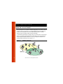
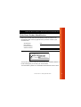
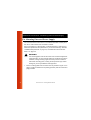
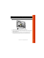
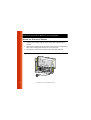
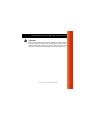
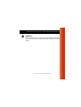
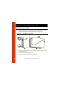
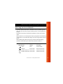
Table of Contents
1
2
3
Welcome
Introducing the Avaya Wireless LAN
1-1
About the Access Point-II
1-2
Finding Information
1-4
Install the Access Point-II
Overview
2-1
Verify Kit Contents
2-2
Write Down Product Identification
2-3
Fix Mounting Plate and Power Supply
2-4
Mount the Processor Module
2-6
Connect the Network Interfaces
2-8
Mount the Cover Plate
2-10
Power up your Access Point-II
2-11
Using the Access Point-II
Connect Computers to the Access Point-II
Access Point-II - Getting Started Guide
3-1
i
A
B
ii
Customize your Access Point-II
■
Install the AP Manager Software
3-3
3-3
Installation Requirements
3-4
Best Place for the Access Point-II
3-5
Remove the Cover Plate
3-6
Specifications
Hardware
A-1
Software
A-2
Regulatory Information
A-3
Start-up Configuration
Access Point-II - Getting Started Guide
1
Welcome
Introducing the Avaya Wireless LAN
Welcome to the Avaya Wireless LAN, the easy way to wireless computing.
Building your wireless network has never been easier.
This booklet introduces you to the Access Point-II, and will help you to get
your network “on the air” very quickly. It describes the most common
configurations and a quick start set-up.
To install and manage Avaya Wireless LAN products, it is assumed that you
have a working knowledge of installation procedures for network operating
systems under Microsoft Windows.
Access Point-II - Getting Started Guide
1-1
Welcome - About the Access Point-II
About the Access Point-II
The Access Point-II is a wired to wireless bridge that you can use to connect
wireless cells to one another or to a wired (Ethernet) Local Area Network
(LAN). The access point can serve mobile wireless stations, roaming
between various locations within a network premises.
To extend the total wireless coverage area you can add one or more Access
Point-Is. In multiple cell networks the Access Point-Is are connected via a
wired backbone that also allows to connect your wireless network to an
existing wired infrastructure (see Figure 1-1).
Figure 1-1
1-2
Multiple Cell Network
Access Point-II - Getting Started Guide
Welcome - About the Access Point-II
The Access Point-II is a modular unit with an integrated Ethernet interface,
and two PC Card slots.
For normal operation you will need to install the Access Point-II with at least
one PC Card. This card is not included with your kit, but must be ordered as
an additional item.
With two PC Cards the unit can transmit at different channels. This allows
you to load balance a heavily used access point and increase the scalability
of the wireless LAN.
NOTE:
If you use your Access Point-II with two PC Cards, you must use at
least one Range Extender Antenna and place it at a distance of at
least 1.5 meters from the Access Point-II.
Access Point-II - Getting Started Guide
1-3
Welcome - Finding Information
Finding Information
The Getting Started Guide was designed to give you a brief introduction
about the Access Point-II, and the most important information to get it up and
running.
When you install the AP Manager program, you can display contextsensitive help with each screen by clicking the ‘
’ or ‘?’ button on your
screen, or pressing the F1 key on your keyboard.
Alternatively you can consult the “Wireless LAN Manager - User’s Guide”
provided on the CD-ROM that was included with your product.
You can use the “Wireless LAN Manager - User’s Guide” to find detailed
information on how to:
1-4
■
Design a wireless network.
■
Setup a LAN administrator station.
■
View and modify the start-up configuration of your Access Point-II.
■
Monitor and optimize the performance of your wireless network.
■
Troubleshoot unexpected performance.
Access Point-II - Getting Started Guide
Install the Access Point-II
2
Overview
Before you start, carefully read the flyer “Information to the User” that is
included in your Access Point-II kit. This flyer contains installation
requirements and important information about using this product.
Installing the Access Point-II is easy. Follow the steps below to power up
your wireless network:
1. Verify Kit Contents.
2. Write Down Product Identification.
3. Fix Mounting Plate and Power Supply.
4. Mount the Processor Module.
5. Connect the Network Interfaces.
6. Mount the Cover Plate.
7. Power up your Access Point-II to start operation.
Access Point-II - Getting Started Guide
2-1
Install the Access Point-II - Verify Kit Contents
Verify Kit Contents
Unpack the Access Point-II and verify that all items are present as pictured
in Figure 2-1.
Figure 2-1
Access Point-II Kit Contents
a. Mounting plate to mount the Access Point-II to a wall (see page 2-4).
b.
2-2
Access Point-II processor module (see page 2-6).
c.
Power supply & AC power cord (see page 2-4).
d.
Slot Protector Card (see page 2-8).
e.
Cover plate (see page 2-10).
f.
Getting Started Guide (this document).
g.
CD-ROM containing software and electronic documentation.
Access Point-II - Getting Started Guide
Install the Access Point-II - Write Down Product Identification
Write Down Product Identification
Before you proceed, write down the following values as printed on the
identification label on the top right side of the processor module of your
Access Point-II.
Serial Number
S/N
MAC Address
Ethernet Interface
Wireless Interface
Figure 2-2
Access Point-II Identification Label
You are also advised to write down the Serial Number and MAC Address of
the PC Card(s) that you use with your Access Point-II.
This information is printed on a small label at the backside of the PC Card.
Access Point-II - Getting Started Guide
2-3
Install the Access Point-II - Fix Mounting Plate and Power Supply
Fix Mounting Plate and Power Supply
You can mount the Access Point-II on a vertical surface like a wall or place
the unit on a flat surface such as a table or cabinet.
Prior to mounting it to a fixed location, consider performing a site survey to
determine optimal and safe placement for your Access Point-II(s). See also
“Installation Requirements” on page 3-4, and “Best Place for the Access
Point-II” on page 3-5.
!
WARNING:
The mounting plate of the Access Point-II has not been designed for
ceiling mounting. In environments where the unit will be exposed to
vibrations, ceiling mounting might cause the processor module to
slide off the mounting plate, causing severe personal injury and/or
damage to your Avaya Wireless LAN equipment.
1. Fix the mounting plate of the Access Point-II as pictured in Figure 2-3 on
page 2-5 (with the marked arrow pointing upwards). Use the screws and
plugs provided.
2-4
Access Point-II - Getting Started Guide
Install the Access Point-II - Fix Mounting Plate and Power Supply
Figure 2-3
Mounting the Power Supply
2. Connect the AC power cord to the power supply unit.
3. Place the power supply unit at the mid section of the mounting plate as
pictured in Figure 2-3.
4. Use tie-wraps to secure the power cord to the small loops on the
mounting plate at the position where the cords will leave the unit.
Access Point-II - Getting Started Guide
2-5
Install the Access Point-II - Mount the Processor Module
Mount the Processor Module
1. Connect the DC power cable to the DC power inlet of the processor
module.
2. Slide the four recesses of the processor module over the corresponding
tabs on the mounting plate (see Figure 2-4 on page 2-6).
3. Press firmly to assure the processor module is properly attached.
Figure 2-4
2-6
Attaching the Processor Module
Access Point-II - Getting Started Guide
Install the Access Point-II - Mount the Processor Module
!
CAUTION:
Before you proceed: Verify that all four recesses are fitted correctly
onto the corresponding tabs of the mounting plate. If the processor
module is not properly seated, it may drop causing severe personal
injury and/or causing serious damage to the Access Point-II unit.
Access Point-II - Getting Started Guide
2-7
Install the Access Point-II - Connect the Network Interfaces
Connect the Network Interfaces
1. Insert your PC Card(s) into the processor module.
One PC Card slot of the Access Point-II is equipped with a plastic Slot
Protector Card. The purpose of this card is to protect the unit from dust
when it is used with a single PC Card. Only when you intend to install two
PC Cards, take out the Slot Protector Card. You are advised to keep the
Slot Protector Card for situations when you would like to change the
hardware configuration in the future.
Figure 2-5
Inserting the PC Card
2. (Optional) Connect your Ethernet cable to the 10/100Base-T Ethernet
interface. Use tie-wraps to secure the Ethernet cable to the small loops
on the mounting plate at the position where the cable will leave the unit.
2-8
Access Point-II - Getting Started Guide
Install the Access Point-II - Connect the Network Interfaces
!
WARNING:
When using the device in combination with our Power over Ethernet
(Active Ethernet) solution, always use Shielded Twisted Pair (STP)
cabling.
Access Point-II - Getting Started Guide
2-9
Install the Access Point-II - Mount the Cover Plate
Mount the Cover Plate
1. Position the latches at the inside of the cover underneath the rim at the
bottom of the processor module (see arrow-1 in Figure 2-6).
Figure 2-6
Mounting the Cover Plate
2. Gently press the top of the cover plate towards the unit until it clicks (see
arrow-2 in Figure 2-6).
3. Verify that the unit is properly seated.
4. Power up the device as described on page 2-11.
2-10
Access Point-II - Getting Started Guide
Install the Access Point-II - Power up your Access Point-II
Power up your Access Point-II
To power up the Access Point-II, connect the unit to a grounding type AC
wall-outlet (100-240 VAC) using the standard power cord as supplied with
the unit.
Placement must allow for easily disconnecting the unit from the AC walloutlet.
When powered on, the unit will perform start-up diagnostics characterized by
a LED sequence. The LEDs will change color in the range Amber, Red and
Green.
When finished (after about 60 seconds), the device will start bridging
operation characterized by the LED activity as listed in Table 2-7.
Table 2-7
LED Activity Table
LED Definition
Activity
Description
Power
Green
Power enabled
Ethernet
Flicker Green
Ethernet LAN activity
A
Wireless interface A Flicker Green
Wireless LAN activity
B
Wireless interface B Flicker Green
Wireless LAN activity
Access Point-II - Getting Started Guide
2-11
Install the Access Point-II - Power up your Access Point-II
LED activity will only occur when there is network activity on the
corresponding Access Point-II network interface.
If the Access Point-II does not switch to normal operation within two minutes,
please consult the troubleshooting section of the “Wireless LAN Manager User’s Guide” (see “Finding Information” on page 1-4).
2-12
Access Point-II - Getting Started Guide
Using the Access Point-II
3
Connect Computers to the Access Point-II
When powering up the Access Point-II for the first time, your Access Point-II
is ready for use.
The unit will start bridging operation using the parameters as listed in
appendix B “Start-up Configuration”.
This mode enables you to connect wireless computers to your Access PointII, provided that they have been configured to use Avaya Wireless LAN
parameter values that match the configuration of your Access Point-II.
Access Point-II - Getting Started Guide
3-1
Using the Access Point-II - Connect Computers to the Access Point-II
To connect stations to a brand new Access Point-II:
■
Set the configuration profile of the wireless client stations to connect to
an “Access Point”.
■
Set the Network Name to “ANY”.
■
Leave Encryption disabled.
For more information, please refer to the documentation that was shipped
with your Avaya Wireless LAN client devices.
3-2
Access Point-II - Getting Started Guide
Using the Access Point-II - Customize your Access Point-II
Customize your Access Point-II
For example, you can use the AP Manager to change the Network Name
and to enable wireless data encryption.
Install the AP Manager Software
1. Insert the Avaya Wireless LAN CD-ROM in the CD-ROM player of your
computer.
Your operating system will automatically start the CD.
2. Follow the instructions on your screen.
NOTE:
If the CD-ROM does not start automatically:
1. Click the Windows Start button
2.
Select Run
3.
Browse to the CD-ROM
Previously installed versions of the software will be replaced automatically.
The installation program will not delete or overwrite back-ups of configuration
files that you might have created with a previous version of the program.
Access Point-II - Getting Started Guide
3-3
Using the Access Point-II - Installation Requirements
Installation Requirements
Placement of the Access Point-II must satisfy the following installation
requirements:
a. Connect the unit to a grounding type AC wall outlet (100-240 VAC) using
the standard power cord as supplied with the unit.
b. Placement must allow for easily disconnecting the unit from the AC walloutlet.
c. Do not cover the unit, or block the airflow to the unit with any other
objects. Keep the unit away from excessive heat and humidity and keep
the unit free from vibration and dust.
d. Installation must at all times conform to local regulations.
e. When connecting the unit to an outdoor antenna system, consult the
documentation that came with the outdoor antenna kit for additional
regulatory information, safety instructions and installation requirements.
3-4
Access Point-II - Getting Started Guide
Using the Access Point-II - Best Place for the Access Point-II
Best Place for the Access Point-II
The integrated antennas of PC Cards perform best in an open environment
with as few obstructions as possible. To ensure the best performance:
■
Place the access point as high and as centrally as possible (relative to
the wireless stations in the vicinity).
■
Do not conceal the integrated antennas of the PC Card(s).
■
Optionally you can use the access point in combination with a Range
Extender Antenna (an omni-directional antenna for indoor use). It
enables you to extend the wireless range of the Access Point-II when
connected to a PC Card (see Figure 3-1).
Figure 3-1
Connect a Range Extender Antenna
Access Point-II - Getting Started Guide
3-5
Using the Access Point-II - Remove the Cover Plate
Remove the Cover Plate
Removing the cover plate of the Access Point-II may be required in the
following situations:
■
changing or replacing the PC Card(s), or
■
getting access to the ‘Reboot’ and/or ‘Forced Reload’ buttons on the
processor module.
To remove the cover plate:
1. Place your hands on the cover as pictured Figure 3-2.
2. Gently pull the top of the cover towards you to release the latches
(located inside the cover).
3. Lower the cover to remove it from the processor module.
Figure 3-2
3-6
Remove the Cover Plate
Access Point-II - Getting Started Guide
A
Specifications
Hardware
Physical specifications
Dimensions (hxwxl) 6x18.5x26 cm
Weight
1.75 kg
Power cord length
2 meter
Electrical specifications
Voltage
100-240 V AC, (47-63 Hz)
Current
0.2 A
Power consumption 10 Watt
Temperature and Humidity (no condensing)
Operating
0° to 40° C 20 to 80%
Storage
-40° to 60° C 15 to 95%
Transit
-10° to 50° C 10 to 90%
Network interfaces
Ethernet interface
10/100Base-T RJ 45 female socket
Wireless interface
2 x PC Card Type II slots for PC Cards
Serial interface
RS232 Connector (will be supported in a future release)
Access Point-II - Getting Started Guide
A-1
Specifications - Software
Software
wpntxxx.bin
Factory installed operating software for the Access Point-II. This
software, that is loaded into the FlashROM of the access point,
controls its features and functions.
The ‘xxx’ in the file name refer to the version level of the software.
When new features and functionality become available, you can
upgrade the Access Point-II by uploading the latest software as
described in the “Wireless LAN Manager - User’s Guide”.
wman_ap.exe AP Manager configuration and management software for Access
Point-IIs. This software runs on Windows 95/98/2000/ME and
Windows NT (v4.0).
A-2
Access Point-II - Getting Started Guide
Specifications - Regulatory Information
Regulatory Information
Wireless communication is often subject to local radio regulations. Although
wireless networking products have been designed for operation in the
license-free 2.4 GHz band, local radio regulations may impose a number of
limitations to the use of wireless communication equipment.
NOTE:
Refer to the flyer “Information to the User” for more regulatory
information that may apply in your country.
Access Point-II - Getting Started Guide
A-3
Start-up Configuration
B
Your Access Point-II comes with the access point operating software factory
installed. Together with this software, the access point has also been loaded
with a factory-set configuration, that allows for ‘out-of-the box’ operation.
NOTE:
The ‘factory-set’ configuration should not be confused with a
‘default’ configuration. For example, the device will NOT return to the
‘factory-set’ configuration, but to the ‘default’ configuration, when
performing a ‘reboot’ or ‘forced reload’ (as described in the
“Wireless LAN Manager - User’s Guide” provided on the CD-ROM).
To connect to a Access Point-II, the Avaya Wireless LAN parameters of each
wireless station should be configured to match the values as identified for the
Access Point-II.
■
When powering up the access point for the very first time, these values
should match the values listed in Table B-1.
■
For normal operation these values should match the ones you identified
when configuring the access point. You are advised to record this
information on the Access Point Configuration Record in this appendix.
■
When you set the Access Point-I to ‘forced reload mode’ these values
should match the settings listed in the “Wireless LAN Manager - User’s
Guide”.
Access Point-II - Getting Started Guide
B-1
Start-up Configuration -
NOTE:
Consult the “Wireless LAN Manager - User’s Guide” for detailed
troubleshooting hints and procedures.
B-2
Access Point-II - Getting Started Guide
Start-up Configuration -
Table B-1
Factory-set Start-up Configuration
Access Point-II identifiers
IP Address
Subnet Mask
Read Password
Read/Write Password
Wireless Interface
Network Name
Encryption
RTS/CTS Medium Reservation
Multicast Rate
153.69.254.254
255.255.0.0
public
public
WaveLAN Network
Disabled
Disabled
Auto select 1-2 Mbit/s
When installing multiple Access Point-IIs, each unit should have a unique IP
Address. In environments with DHCP or BOOTP services, this address will
be assigned automatically.
If your network does not provide DHCP or BootP services, change the IP
address of each Access Point-II into a unique address value using the
AP Manager tool.
Access Point-II - Getting Started Guide
B-3