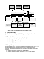
1
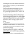
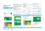
15-413
Handout 2
29 August 1995
15-413 Software Engineering
Carnegie Mellon University
School of Computer Science
Bernd Bruegge
The DAIMLER System
Problem Statement
Table of Contents
1. 1. INTRODUCTION ................................................................................................................................................3
1.1 OVERVIEW .................................................................................................................................................................3
1.2 PREVENTIVE MAINTENANCE......................................................................................................................................3
1.3 CHANGE MANAGEMENT ............................................................................................................................................3
1.4 DIAGNOSTICS .............................................................................................................................................................4
2. REQUIREMENTS....................................................................................................................................................4
2.1 FUNCTIONAL REQUIREMENTS ....................................................................................................................................4
2.1.1 Preventive Maintenance....................................................................................................................................4
2.1.2 Change Management ........................................................................................................................................5
2.1.3 Diagnostics........................................................................................................................................................6
2.1.4 Functionality provided by DAIMLER ...............................................................................................................7
2.2 GLOBAL REQUIREMENTS ...........................................................................................................................................7
2.2.1 Development Environment ................................................................................................................................8
2.2.2 Target Environment ..........................................................................................................................................8
2.2.3 Target Platform.................................................................................................................................................8
3. DESIGN ISSUES ......................................................................................................................................................8
3.1 CLIENT SUBSYSTEMS .................................................................................................................................................9
3.1.1 Preventive Maintenance....................................................................................................................................9
3.1.2 Change Management ........................................................................................................................................9
3.1.3 Diagnostics......................................................................................................................................................10
3.2 SERVER SUBSYSTEMS ..............................................................................................................................................10
3.2.1 Notification Server ..........................................................................................................................................10
3.2.2 Visualization Server ........................................................................................................................................10
3.2.3 ATGS Data Server...........................................................................................................................................10
3.2.4 Communication Server....................................................................................................................................10
1
3.2.5 Database Server ..............................................................................................................................................10
3.2.6 Information Space ...........................................................................................................................................10
3.2.7 System Manager ..............................................................................................................................................11
4. CLIENT ACCEPTANCE ......................................................................................................................................11
4.1 CLIENT ACCEPTANCE SCENARIO: MONITORING THE DOOR CLOSURE TIME ...........................................................11
4.2 DELIVERABLES ........................................................................................................................................................12
1.
2
1. INTRODUCTION
1.1 Overview
The growth of airline passenger traffic in the last decade has created a demand for
larger airports. Unfortunately, large airports create two problems. First, travelers must
walk long distances to get to the departure gate and baggage handling areas. Second, a
considerable amount of time is spent by the airplanes moving on the ground between
passenger gates and runways wasting large amounts of fuel and money.
A solution to both of these problems has been the redesign of airports coupled with the
introduction of Automated Guided Transit Systems (AGTS)—people movers. People
movers are automated trains that move passengers efficiently over long distances.
People movers have two advantages. First, they make it easier for passengers to move
across distances in airports, and second—when placed underground—they eliminate
traffic from the surface allowing planes to move more optimally while navigating to
and from runways. As a result, airport redesign and people movers significantly reduce
the fuel requirements for planes.
By placing people movers between gates and arrival/departure areas, the people
movers become a crucial part of airport operations. In a busy airport, any problem that
causes down time in a people mover has the potential of disturbing thousands of
passengers. Therefore, a major operating requirement for people movers is extremely
high availability.
The goal of the DAIMLER (Distributed Assistant for Intelligent Maintenance in a gLobal
EnviRonment) system is to improve and optimize the flow of information between
engineers performing maintenance on people mover systems. To deal with these goals,
this course focuses on three areas of concern: Preventive Maintenance, Change
Management and Diagnostics.
1.2 Preventive Maintenance
Each year AEG Transportation Systems, Inc. (ATS), a subsidiary of Daimler-Benz
specializing in manufacturing people movers, spends a large amount of time
performing preventive maintenance to keep the availability of people movers above
99%. Preventive maintenance includes all planned activities associated with working on
a vehicle or other component of the people mover. This includes planned inspections,
adjustments, scheduled component replacements, planned engineering changes to the
vehicle, preventive maintenance procedures and schedules, obtaining drawings from
Engineering, and researching maintenance manuals. System availability is calculated
using the Mean Time Between Failures (MTBF) and the Mean Time to Repair (MTTR) of
the system. Preventive maintenance keeps the probability of a product breakdown to a
minimum and improves the availability of the system.
1.3 Change Management
At ATS, as with most companies, things change. Engineers modify design drawings.
Field technicians replace parts on vehicles. Training personnel update manuals.
Managers create new policies. However, people cannot make changes in isolation. A
large company is a loosely connected network of individuals. For a change to take effect
it must be managed. Other employees must be informed of the change if it affects them.
Certain changes must go through an approval process before taking effect. Frequently, a
3
company must maintain an archive of all changes for accountability and to maintain an
organizational memory.
1.4 Diagnostics
Diagnostics involves the analysis of real-time data received from a people mover. Data
indicates the status of various subsystems operating on the people mover. Examining
this information you could diagnose potential problems based on trend analysis. For
example, consider the case where sensors are located on every people mover door to
measure the resistance as these doors open and close. A data analysis tool could use this
sensor information to determine potential problems in the near future by detecting any
constant increase in the resistance of these doors. By alerting maintenance personnel of
this situation, a potentially unfortunate situation or breakdown can be averted.
Moreover, all costs associated with such an incident can be eliminated.
2. Requirements
2.1 Functional Requirements
At the Pittsburgh International Airport (PIA) people movers field site, the first and
second shifts perform inspections of the vehicle system each day while the trains are
running. Inspections cover a wide range of systems and include everything from visual
checks of the interior condition of each vehicle (such as carpeting, windows, fiberglass
integrity, etc.), to tests of the mechanical and electronic systems (such as proper brake
pressure, proper battery voltage, test of propulsion monitor panel), to tests of vehicle
behavior (e.g., testing stopping accuracy). The third shift performs the majority of
preventive and corrective maintenance on the vehicles. Every night one of the trains is
taken out of service and the technicians perform maintenance in accordance with the
schedule.
There are several procedures specified by time, that is daily, weekly, monthly, etc., as
well as several specified by mileage. Procedures range from simple inspections (such as
checking pressure gauges for correct settings) to substantial repairs (such as replacing
steering shocks if they are leaking).
In order for the maintenance technicians to fulfill their tasks during a shift, the
DAIMLER system must provide the following functions.
•
•
•
First, DAIMLER must be able to create a worksheet, a list of the tasks to be
performed by the maintenance technician in the actual shift, and it must be able to
annotate this worksheet with additional information (2.1.1 Preventive Maintenance)
Second, the maintenance technician must be able to pass information on to the next
shift, that is, the task list must be augmentable with information about what has
happened in previous shifts - such as work performed, contact information, and
general background information about the task (2.2.2 Change Management).
Third, the system should provide the ability to diagnose problems that are about to
occur (2.2.3 Diagnostics).
2.1.1 Preventive Maintenance
In the current operation at the Pittsburgh International Airport, two existing systems
are used to support the maintenance technician: SIMS and EDMS. SIMS (Site
Information Management System) manages the worksheets, parts list, reports and other
4
operations data. EDMS (Enterprise Document Management System) provides access to
technical drawings of train components.
There are two problems with these systems: First, although SIMS is computer based,
much of the information exchange still occurs on paper.1 Second, there is no integration
between SIMS and EDMS.
Scenario 1: Routine Maintenance
A maintenance technician equipped with a portable computer or with access to a
desktop near the working area checks the task list at the beginning of the shift. The task
list contains maintenance items generated automatically, action items set by the
previous shift and tasks set by a leading engineer or site manager. To fulfill the check
list, the technician may have to get extra information like manuals or drawings, or may
have to contact other people. Every finished task is marked off in the check list. At the
end of the shift several reports are generated. The technician may add some personal
notes to the reports.
One task of this shift is the change of a traction motor. Because this work is done
infrequently the technician will first want to check the motor change procedures in the
maintenance manual by downloading a drawing of the motor. While performing the
work the technician notices that the delivered motor does not have the same revision
number as the current drawing. The technician checks with the engineering department
to see if the current version is still valid. The communication is done via the telephone
facility on the computer. Before installing the motor on the vehicle it has to be checked.
The technician notices a strange noise while doing this check (which could be caused by
a fan hitting the frame during the initial rotation tests), and decides not to install the
motor until the cause of the noise can be isolated. After completion of the task and
signoff a note is sent to the next shift requesting that the motor be checked and another
note is sent to the parts management system, notifying it that a new engine may have to
be ordered.
2.1.2 Change Management
To support the information flow and to provide an action channel between Field Sites
and ATS Headquarters several standard operation procedures are used. The carrier for
this information are paper based forms, initiating a process wherein a variety of people
and departments are involved.
One of these forms is the Field Action Request (FAR) issued whenever investigation of
an equipment problem is required, quality problems have been noted, or drawings are
requested to be changed on the field site.
Another form is the Temporary Change Authorization (TCA): it provides a means of
documenting the temporary modification of existing equipment for a defined
evaluation period. This change is not to be made until the TCA is approved by his
immediate manager and sent to the Field Support Headquarters Administrator. The
administrator must log it and send it to the appropriate people for approval, including
the cognizant equipment engineer at Headquarters, the cognizant equipment engineer's
1
Examples are the daily inspection worksheet, the shut down inspection worksheet, the 30 day
preventive maintenance forecast, maintenance task list and the preventive maintenance descriptions are
all still done on paper.
5
manager at Headquarters, the project lead engineer, the program manager (when
applicable), and the manager of Headquarters field support. Once the approvals are
obtained, the Field Site Administrator redistributes the approved TCA. Only at this
point should the temporary change be made. A large number of TCAs are issued
during initial field site start-up.
Scenario 2: Feedback to Engineering
An engineer at ATS headquarters needs some relevant data for product improvement.
From the engineer’s workstation a video conferencing session is initiated with a
maintenance technician at Pittsburgh International Airport. Both participants access an
integrated information space and discuss a procedure relating to component in
question . Using the information space, the team reviews FARs, TCAs and public
annotations stored by field personnel on maintenance procedures that involve the
component.
2.1.3 Diagnostics
The current reliability of AEG people movers is relatively low, about 10-2 failures per
hour for a complete train. The company’s goal is to raise the overall reliability of the
complete train to 10-5 failures per hour. For safety critical items, the overall reliability
should even be less than 10-9 failures per hour. In practice, this means if a people mover
runs from Pittsburgh to San Francisco, the people mover will fail once. With 10-5 failures
per hour, the people mover can run around the world one hundred times without
failure.
Availability is a function of two components, MTBF (Mean Time Between Failures) and
MTTR ( Mean Time to Repair):
A ≡ MTBF MTBF + MTTR
Reducing the MTBF involves hardware changes and redesign of the sensor architecture
on the people mover. Reducing MTTR involves an improvement of the maintenance
process, which is feasible without hardware changes.
In this project we will therefore try to increase availability first by reducing MTTR (by
improving the maintenance process). In the long term, we envision a proposal that
includes recommended hardware changes as well.
A large percentage of all maintenance problems in a people mover are door-related:
Because of the moving parts they have a high probability of failure. The availability of
the door system could be improved by minimizing the number of door repairs needed
during regular operation of the train and - if there is a need - by scheduling the repairs
for preventive maintenance described in Scenario 1. (As with all failures, you are better
off if you detect the problem before it occurs).
Scenario 3: Event-Driven Maintenance of the Door System
There is a well-known relationship between the time it takes for the doors to close and
the probability of a door failure: At PIA, a door closure of more than 5 seconds can lead
to many problems if not corrected. For example, the doors can become loose and start to
rub as they slide along the vehicle, which will eventually lead to a door failure.
6
Alternatively, a foreign object could be caught in the door slide and the motor could
overload over a period of time. A trend analysis system recognizes a degradation of the
door closure time during the operation of a people mover, and schedules the necessary
door maintenance task before a problem occurs.
2.1.4 Functionality provided by DAIMLER
Derived from the three scenarios described above, the DAIMLER system should
provide the following functionality:
•
•
•
•
•
•
•
•
•
•
•
•
•
•
•
•
•
•
Generate an on-line worksheet and check lists
Provide information about actions in previous shifts
Search documents, manuals, drawings
Browse through documents, manuals and drawings
Establish communication to other people (technicians, central)
Provide facility for personal annotations
Provide facility to share information
Provide facility to report status of work
Provide interface to existing systems (SIMS, EDMS)
Provide video conferencing connectivity
Annotate a document
Notify other people and systems of a change
Provide access rights for documents
Approve a change
Archive a change
Provide real-time recording of sensor data
Wireless transmission of data (Send/Receive) using different wireless
technologies
Provide a trend analysis system for the recognition of door closure problems
2.2 Global Requirements
The people mover must have a mobile data computer interface to the DAIMLER
system. The user interface should be designed for easy input and response. Voice
recognition, touch screen or pen based systems are desirable. The goal is to reduce the
Field Service Engineer's need for input as much as possible. A manual response should
be limited to buttons or check off boxes to explain needs, situation, or status.
The design of the DAIMLER system must be modular and reusable. Each of the
subsystems must be designed to be usable in other target environments. The design
must also be scaleable, that is, it must be able to handle large sets of check lists,
worksheets, sensors and changes as well as it does small sets.
All transactions on the DAIMLER system will be saved for future analysis. Information
from responses will be used for report writing, investigations, training, response
planning, legal action and approval for distribution.
The DAIMLER system must be delivered with recommendations for equipment
upgrade. Equipment upgrade must be compatible with existing equipment and
applications.
7
2.2.1 Development Environment
The development of DAIMLER makes use of the facilities offered in the clusters on
CMU Campus as well as the Vehicle Systems Laboratory located at Building D, Room
154A. While the clusters are shared with other students taking other courses, the
resources at the vehicle lab are to be used solely for the development of DAIMLER.
2.2.2 Target Environment
The DAIMLER system is to be used by Pittsburgh International Airport personnel for
preventive, corrective, and predictive maintenance. The system should work as a stand
alone service within the People Mover Maintenance Site at Pittsburgh Airport.
DAIMLER users include all field service personnel associated with AGTS. Every
technician has access to a portable/ wireless computer which must be operational
under rough duty. The user interface must take these conditions into account during the
development phase.
The system should be portable to existing hardware available at AEG Transportation,
consisting mostly of DOS and Windows based machines.
2.2.3 Target Platform
The Pittsburgh International Airport operates a local area network (LAN) consisting of
a set of PCs. Some of these are connected via Ethernet. Others have access to the
network via wireless communication. AT&T WaveLAN cards and CDPD must be used
to support the wireless communication between the nodes.
.....<< Need description of hardware/software environment at PIA>>
3. Design Issues
A system dealing with the scenarios described in the previous sections will be complex
and will require a multi-team effort. We have decomposed the system into a clientserver architecture shown in Figure 1. In this architecture, clients named Diagnostics,
Change Management and Vehicle Maintenance are accessing a set of servers named
Communication, Database, Notification, Visualization, and AGTS.
8
Diagnos tic
Change
Management
Preventive
Maintenance
API
API
API
A
P
I
AMEFS Object Reques t Broker
API
API
API
API
Communication
S erver
Databas e
S erver
N otification
S erver
Vis ualization
S erver
Information
S pace
ATGS Data
EDMS,
3-D Models
FAR,TCA,...
S ys tem
Manager
API
AGTS
S erver
SIMS,
Work Orders
Figure 1 Top-Level Decomposition of the DAIMLER System
3.1 Client Subsystems
From the clients shown in Figure 1, the following functionality has to be implemented
this semester.
3.1.1 Preventive Maintenance
• Generate an on-line worksheet and on-line check-lists
• Provide information about actions in previous shifts
• Provide facility for personal annotations
• Provide facility to share information
• Provide facility to report status of work
• Annotate a document
3.1.2 Change Management
This subsystem provides a set of policies for change management of FARs and TCAs. It
uses the information space and annotations provided by the Information Space
Subsystem. The following functions should be provided by the Change Management
subsystem:
• Manage a Field Action Request (Create, Submit, Read)
• Manage a Temporary Change Authorization (Create, Forward, Archive)
9
3.1.3 Diagnostics
• Provide a taxonomy of the available sensors on the people mover
• Provide real-time collection of sensor values on train
• Provide filtering of event data
• Allow for push and pull sensor information
• Provide transmission of sensor values off the train to the field site
• Provide appropriate visualizations (time lines, histograms of original and
derived data)
• Provide archiving of event data
3.2 Server Subsystems
3.2.1 Notification Server
• Notify other people and subsystems of a change
• Allow subscription to a change
• Provide subscription to an event
• Provide notification when an event occurs (point to point, multicast and
broadcast)
3.2.2 Visualization Server
• Provide visualizations such as histograms, pie charts, and time lines for events
• Provide the ability for customized views
• Provide the ability for aggregate views
• Provide some of these views for operation under real-time constraints
3.2.3 ATGS Data Server
• Collect sensor data coming from People Mover
• Augment these sensor data with timing information (currently no time is
recorded when sensor data are coming from the train)
• Store all these sensor data in an event database
• Transmit control information between Central control and the People Mover
3.2.4 Communication Server
• Provide a communication subsystem that allows the rest of the system to forget
about the underlying physical layer and communication medium
• Support wireless and wired communication. The wireless communication must
use Spread Spectrum Transmission (SST) and Cellular Digital Packet Data
(CDPD). The wired communication must include Ethernet
• Provide a connection for text, voice and video as a parameter of cost, bandwidth
and coverage
3.2.5 Database Server
• Provide an interface to legacy systems (SIMS, EDMS)
• Provide a data model that integrates SIMS and EDMS
• Set access rights for a document
3.2.6 Information Space
• Search documents, manuals, and drawings
• Annotate a document
10
•
•
•
•
Browse through documents, manuals and drawings
Provide access rights for documents
Create annotations for documents, allowing customized viewing of any kind of
document. Starting from the latest edition of a document, allow three types of
annotations:
• Corporate annotations: Changes approved by headquarters
• Field site annotations
• Personal annotations
Allow changes to be static (valid until the annotator deletes the annotation) or
dynamic (valid until the next document release)
3.2.7 System Manager
• Provide for disconnected operation
• Register all clients and services
• Provide a policy for data caching mechanism
• Provide a scaleable solution for connecting many wireless components in the
system
• Be able to allow the user and subsystems (Clients, Servers) to be aware of
changes in the communication topology
4. Client Acceptance
The client considers this problem statement to be a broad definition and does not expect
that all the functionality mentioned in this document will be demonstrated at the end of
this semester. However, the analysis and design should be extensible to include this
functionality in a future version of the system.
During the requirements analysis phase of the project the client will negotiate with the
software engineers an acceptable prototype for delivery. After the negotiation phase the
specific requirements for the client acceptance test will be baselined. The client expects
to sign off on the negotiated deliverables within 4-6 weeks of the client presentation.
For a demonstration of the system on client acceptance day, the following scenario will
be used.
4.1 Client Acceptance Scenario: Monitoring the Door Closure Time
Every time a train berths into a station, its doors are commanded open and remain open
for an adjustable dwell time which is on the order of 30-45 seconds. After the expiration
of the dwell time, a signal is sent to the car to close the door. As described above, it is
important that the Door Closure Time - the time difference between sending the
command and the doors actually being shut - is not too long.
To monitor the Door Closure Time, three sensors values are transmitted via wireless
communication in real time:
• CLOSE DOOR, the control signal sent from Automatic Train Control (AGO) to the
cars. This signal is generated by computers in the ATO shuttle cabinetts.
• DOOR IS ACTUALLY CLOSED, a data signal that reports the actual status of the
door. This signal is generated by a sensor on the car.
• SAFETY EDGE, a data signal that reports when somebody has interfered with the
door closure. This signal is also generated by a sensor on the car.
11
When the Door Closure Time is measured to be longer than TIME_MAX1 seconds more
than ten times during the daily operation of a train, a door maintenance task has to be
created and added to the worksheet for the second shift (note that this situation is not
currently considered an event, because it does not signal an alarm).
In the second shift, the maintenance technicians receive a worksheet (see Handout 4)
with the task of checking the door closure. They follow the routine maintenance
procedures for each of the tasks described in the worksheet. During the door closure
task, they request a drawing of the door and applicable maintenance manual sections
and circle the troublesome part, marking how it is damaged. They send this drawing
electronically to the field service engineer. The field service engineer finds that most of
the maintenance in the past has been on a poorly designed roller. The engineer issues a
FAR in electronic form that this part should be changed to a different material, because
it is the source of constant problems. This FAR is sent to the FAR administrator (Jack
Fry) at headquarters with a copy to the field site manager (Bill Main) and site engineer
(Chuck Adams). Within (a simulated) 30 days, engineering at headquarters has found a
different part and issues a temporary change authorization (TCA) which is sent
electronically, asking the field site to evaluate the new part for 30 days.
4.2 Deliverables
The client expects the above scenario to be successfully demonstrated in a field trial
with a people mover at the Pittsburgh International Airport (PIA) on Dec. 14, 1995
during the second shift at 3:30pm-5:00pm. A set of documents on a CD-ROM describing
the requirements analysis (RAD), the system design (SDD), object design (ODD), testing
procedures (TM) and user manual of the DAIMLER system should accompany the
demonstration.
If a demonstration at PIA is not possible, a minimum acceptable test is a demonstration
of the client acceptance scenario in the Vehicle Systems Lab, Carnegie Mellon
University, Building D-154.
1
The value of TIME_MAX is about 5 seconds, but it must be changeable so the occurrence of this event
can be demonstrated with real train data during the client acceptance test.
12
Action Items
We need intro paragraphs for sections:
3.1.3, 3.1.2, 3.2.2, 3.2.3, ... (there are many more of these).
Also:
• Description of target platform needed
• Description of target environment needed
13