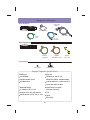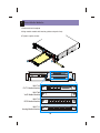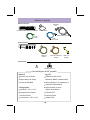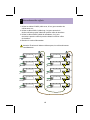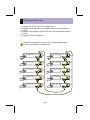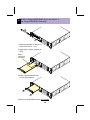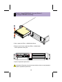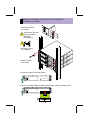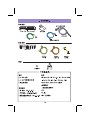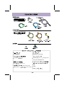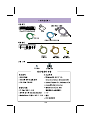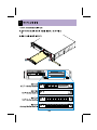
1
234201_1_title.fm Page i Thursday, March 7, 2002 12:06 PM Installation Quick Reference for AvayaTM S8300 Media Server and the AvayaTM G700 Media Gateway Languages This Quick Reference is provided in the following languages: • English 3 • Français 17 • Deutsch 31 • Italiano 45 • Português brasileiro 59 • Español para América Latina 73 • 87 • 99 • 113 555-234-201 Comcode 700211824 Issue 1 May 2002 234201_1_title.fm Page i Friday, March 22, 2002 3:14 PM Installation Quick Reference IRU $YD\D60HGLD6HUYHU ZLWK$YD\D*0HGLD*DWHZD\ 555-234-201 Issue 1 May 2002 3 234201_1_title.fm Page ii Thursday, March 7, 2002 12:06 PM Copyright 2002, Avaya Inc. All Rights Reserved Notice Every effort was made to ensure that the information in this document was complete and accurate at the time of printing. However, information is subject to change. Your Responsibility for Your Company’s Telecommunications Security The final responsibility for securing both this system and its networked equipment rests with you - an Avaya customer’s system administrator, your telecommunications peers, and your managers. The scope of your responsibilities is based upon acquired knowledge and resources from a variety of sources including but not limited to: • Installation documents • System administration documents • Security documents • Hardware-/software-based security tools • Shared information between you and your peers • Telecommunications security experts To prevent intrusions to your telecommunications equipment, you and your peers should carefully program and configure: • Your Avaya-provided telecommunications systems and their interfaces • Your Avaya-provided software applications, and their underlying hardware/software platforms and interfaces • Any other equipment networked to your Avaya products. Preventing Toll Fraud “Toll fraud” is the unauthorized use of your telecommunications system by an unauthorized party (for example, a person who is not a corporate employee, agent, subcontractor, or is not working on your company's behalf). Be aware that there may be a risk of toll fraud associated with your system and that, if toll fraud occurs, it can result in substantial additional charges for your telecommunications services. Avaya Fraud Intervention and how to get help If you suspect that you are being victimized by toll fraud and you need technical assistance or support, in the United States and Canada, call the Technical Service Center's Toll Fraud Intervention Hotline at 1-800-643-2353. For additional support telephone numbers, see the Avaya web site: http://www.avaya.com Click on Support, click on Escalation Lists US and International. This web site includes phone numbers for escalation within the United States. For escalation phone numbers outside the United States, click on Global Escalation List. This list contains the phone numbers for the Centers of Excellence in each Avaya-defined region. Voice over Internet Protocol (VoIP) If the equipment supports Voice over Internet Protocol (VoIP) facilities, you may experience certain compromises in performance, reliability and security, even when the equipment performs as warranted. These compromises may become more acute if you fail to follow Avaya’s recommendations for configuration, operation and use of the equipment. YOU ACKNOWLEDGE THAT YOU ARE AWARE OF THESE RISKS AND THAT YOU HAVE DETERMINED THEY ARE ACCEPTABLE FOR YOUR APPLICATION OF THE EQUIPMENT. YOU ALSO ACKNOWLEDGE THAT, UNLESS EXPRESSLY PROVIDED IN ANOTHER AGREEMENT, YOU ARE SOLELY RESPONSIBLE FOR (1) ENSURING THAT YOUR NETWORKS AND SYSTEMS ARE ADEQUATELY SECURED AGAINST UNAUTHORIZED INTRUSION AND (2) BACKING UP YOUR DATA AND FILES. Standards Compliance Avaya Inc. is not responsible for any radio or television interference caused by unauthorized modifications of this equipment or the substitution or attachment of connecting cables and equipment other than those specified by Avaya Inc. The correction of interference caused by such unauthorized modifications, substitution or attachment will be the responsibility of the user. Pursuant to Part 15 of the FCC Rules, the user is cautioned that changes or modifications not expressly approved by Avaya Inc. could void the user’s authority to operate this equipment. Ordering Information Call: Write: Order: US Voice: 1 800 457 1235 US Fax: 1 800 457 1764 non-US Voice: +1 410 568 3680 non-US Fax: +1 410 891 0207 Globalware Solutions 200 Ward Hill Avenue Haverhill, MA 01835 USA Document No.555-234-201, Issue 1, May 2002 European Union Declaration of Conformity Avaya Inc. declares that the equipment specified in this document bearing the “CE” (Conformité Europeénne) mark conforms to the European Union Radio and Telecommunications Terminal Equipment Directive (1999/5/EC), including the Electromagnetic Compatibility Directive (89/336/EEC, Class B) and Low Voltage Directive (73/23/EEC). This equipment has been tested to meet the CTR4 Primary Rate Interface (PRI) specification. . Copies of these Declarations of Conformity (DoCs) can be obtained by contacting your local sales representative and are available on the following Web site: http://support.avaya.com/elmodocs2/DoC/IDoC/index.jhtml/ 4 234201_1_title.fm Page iii Thursday, March 7, 2002 12:06 PM Federal Communications Commission Statement Means of Connection Part 15: Note: This equipment has been tested and found to comply with the limits for a Class B digital device, pursuant to Part 15 of the FCC Rules. These limits are designed to provide reasonable protection against harmful interference in a residential installation. This equipment generates, uses, and can radiate radio frequency energy and, if not installed and used in accordance with the instruction manual, may cause harmful interference to radio communications. However, there is no guarantee that interference will not occur in a particular installation. If this equipment does cause harmful interference to radio or television reception, which can be determined by turning the equipment off and on, the user is encouraged to try to correct the interference by one or more of the following measures: • Reorient or relocate the receiving antenna. • Increase the separation between the equipment and receiver. • Connect the equipment into an outlet on a circuit different from that to which the receiver is connected. • Consult the dealer or an experienced radio/TV technician for help. Connection of this equipment to the telephone network is shown in the following table. Part 68: Answer-Supervision Signaling. Allowing this equipment to be operated in a manner that does not provide proper answer-supervision signaling is in violation of Part 68 rules. This equipment returns answer-supervision signals to the public switched network when: • answered by the called station, • answered by the attendant, or • routed to a recorded announcement that can be administered by the customer premises equipment (CPE) user. • This equipment returns answer-supervision signals on all direct inward dialed (DID) calls forwarded back to the public switched telephone network. Permissible exceptions are: • A call is unanswered. • A busy tone is received. • A reorder tone is received. Avaya attests that this registered equipment is capable of providing users access to interstate providers of operator services through the use of access codes. Modification of this equipment by call aggregators to block access dialing codes is a violation of the Telephone Operator Consumers Act of 1990. This equipment complies with Part 68 of the FCC Rules. On the rear of this equipment is a label that contains, among other information, the FCC registration number and ringer equivalence number (REN) for this equipment. If requested, this information must be provided to the telephone company. The REN is used to determine the quantity of devices which may be connected to the telephone line. Excessive RENs on the telephone line may result in devices not ringing in response to an incoming call. In most, but not all areas, the sum of RENs should not exceed 5.0. To be certain of the number of devices that may be connected to a line, as determined by the total RENs, contact the local telephone company. REN is not required for some types of analog or digital facilities. 5 Manufacturer’s Port Identifier FIC Code SOC/ REN/ A.S. Code Network Jacks Ground start CO trunk 02GS2 0.5A RJ11C Loop start CO trunk 02LS2 0.5A RJ11C DID CO trunk 02RV2-T AS.2 RJ11C 1.544 Mbit digital interface 04DU9-BN 04DU9-DN 04DU9-IKN 04DU9-ISN 6.0Y 6.0Y 6.0Y 6.0Y RJ48C RJ48C RJ48C RJ48C Primary Rate Interface 04DU9ISN(PRI) 6.0Y RJ48C Basic Rate Interface 02IS5 6.0F RJ49C If the terminal equipment causes harm to the telephone network, the telephone company will notify you in advance that temporary discontinuance of service may be required. But if advance notice is not practical, the telephone company will notify the customer as soon as possible. Also, you will be advised of your right to file a complaint with the FCC if you believe it is necessary. The telephone company may make changes in its facilities, equipment, operations or procedures that could affect the operation of the equipment. If this happens, the telephone company will provide advance notice in order for you to make necessary modifications to maintain uninterrupted service. If trouble is experienced with this equipment, for repair or warranty information, please contact the Technical Service Center at 1-800-242-2121 or contact your local Avaya representative. If the equipment is causing harm to the telephone network, the telephone company may request that you disconnect the equipment until the problem is resolved. It is recommended that repairs be performed by Avaya certified technicians. The equipment cannot be used on public coin phone service provided by the telephone company. Connection to party line service is subject to state tariffs. Contact the state public utility commission, public service commission or corporation commission for information. This equipment, if it uses a telephone receiver, is hearing aid compatible. 234201_1_title.fm Page iv Thursday, March 7, 2002 12:06 PM 6 Cajun P330 BUPS OUT 1 OUT 2 OUT 3 OUT 4 FAN EI SM EM 1 SO 2 3 4 5 6 7 8 1 2 3 4 5 6 7 8 ALM TST ACT SIG SI EO E1/T1 ALM TST ACT OK TO REMOVE EIA 530A DCE ALM TST ACT SHUT DOWN SERVICES USB 1 USB 2 ALM TST ACT EI SM EM 1 SO 2 3 4 5 6 7 8 1 2 3 4 5 6 7 8 ALM TST ACT SIG SI EO E1/T1 ALM TST ACT OK TO REMOVE EIA 530A DCE ALM TST ACT SHUT DOWN SERVICES USB 1 USB 2 ALM TST ACT EI SM EM 1 SO 2 3 4 5 6 7 8 1 2 3 4 5 6 7 8 ALM TST ACT SIG SI EO E1/T1 ALM TST ACT OK TO REMOVE EIA 530A DCE ALM TST ACT SHUT DOWN SERVICES USB 1 USB 2 ALM TST ACT EI SM EM 1 SO 2 3 4 5 6 7 8 1 2 3 4 5 6 7 8 ALM TST ACT SIG SI EO E1/T1 ALM TST ACT OK TO REMOVE EIA 530A DCE ALM TST ACT SHUT DOWN SERVICES USB 1 USB 2 ALM TST ACT 1 Mount in Rack 2 Insert S8300 Media Server 3 Insert Media Modules 4 Connect the Units 5 Assign IP Addresses 6 Configure S8300 Media Server 7 Connect to LAN 7 - Equipment and Legend Basic Shipment ALM PWR CPU MSTR LNK COL Tx Rx FDX FC 52 53 54 55 56 57 58 60 61 62 63 64 65 66 EXT 1 EXT 2 SO SI Serial cable adapter EI SM EM 1 2 3 4 5 6 7 8 1 2 3 4 5 6 7 8 ALM TST ACT SIG EO E1/T1 EIA 530A DCE ALM TST ACT SHUT DOWN SERVICES USB 1 USB 2 n tio ta en m ALM TST ACT OK TO REMOVE u oc D 51 59 Hspd ALM TST ACT Avaya G700 Media Gateway Documentation Serial cable Ground wire Crossover ethernet cable Other Equipment Cajun P330 BUPS OUT 1 OUT 2 OUT 3 OUT 4 FAN Cajun P330 X330LC Long cable X330RC Redundancy cable X330SC Short cable Conventions 2 Step number Customer LAN Laptop Computer Specifications Hardware Software 32 MB RAM Windows 95, 98, NT 4.0, 40 MB free disk space Millennium Edition, Windows 2000 CD-ROM drive Internet Explorer 5.x, Netscape 4.7x Avaya Site Administration HyperTerminal (or other Terminal Setup IP address: 192.11.13.5 emulation software) Subnet mask: 255.255.255.252 FTP Media Server access: 192.11.13.6 Telnet SSH utility 8 1 Mount in Rack, Attach Grounds and Install Cascade Module 1. Install mounting brackets Warning! Use ESD strap. 1 2 2. Balance and mount in the rack 3 3. Insert and tighten screws 3 4. Attach ground wire 4 5. Insert the Octaplane Stacking Module to link multiple G700s 5 X330STK Cable to lower unit Cable to lower unit 9 Insert Avaya S8300 Media Server into Slot #1 2a of Avaya G700 Media Gateway 1 2 1. Remove blank faceplate on Avaya G700 slot #1 (V1) 2. Disengage and remove LED panel Optional messaging module 3 ALM TST AC OK T RE TO MO VE SH UT DO WN SE RV ICE S US B1 US B2 3. Align S8300 Media Server with internal guides ALM TST AC OK T RE TO MO VE SH UT DO WN 4 SE RV ICE S US B1 US B2 4 4. Push in S8300 Media Server halfway 10 Insert Avaya S8300 Media Server into Slot #1 of Avaya G700 Media Gateway 2b 5 6 AL M TS ACT O T REK TO MO VE SH UT DO WN 6 SE RV ICES US B1 US B2 5 5. Align LED panel and S8300 Media Server 6. Push both LED panel and S8300 Media Server firmly into guides 7 V1 V2 ALM TST ACT OK TO REMOVE V3 SHUT DOWN SERVICES USB 1 USB 2 V4 7. Tighten captive screws Warning! To prevent electrical hazards faceplates must be used and captive screws must be tightened. 11 3 Insert Media Modules 1. Remove blank faceplate 2. Align media module with interior guides and push firmly 3. Tighten captive screws ALM TS ACT OK T RE TO MO VE SH UT DO WN SE RV ICE S US B1 US B2 3 2 ALM TS T AC SIGT 1 SO EI E1 /T SM 1 EM SI EO ALM PWR CPU MSTR V1 ALM TST ACT OK TO REMOVE LNK COL Tx Rx FDX FC 51 52 53 54 55 56 57 58 59 60 61 62 63 64 65 66 MM 712 DCP Media Module MM 711 Analog Media Module EO EIA 530A DCE ALM TST ACT 1 MM 760 VoIP Media Module SI USB 2 V4 MM 710 E1/T1 Media Module SM EM ALM TST ACT V3 USB 1 EI E1/T1 SHUT DOWN SERVICES SO ALM TST ACT SIG V2 EXT 1 EXT 2 Hspd SO ALM TST ACT SIG EI 2 SM EM 3 4 SI 5 6 7 8 EO E1/T1 EIA 530A DCE ALM TST ACT ALM TST ACT 1 2 3 4 5 6 7 8 1 2 3 4 5 6 7 8 ALM TST ACT 12 4 Connect the Units 1. Connect units with X330SC (Short Cable) 12in./30 cm 2. Link units in separate racks with X330LC (Long Cable) 6'/2m 3. Link bottom to top unit with X330RC (Redundancy Cable) 6'/2m 4. Attach power cable Warning: There is no On/Off switch - units will powerup immediately! 2 3 10 5 4 4 1 1 4 9 3 8 2 7 1 6 13 5 Assign an IP Address to the Cajun Stack and the G700 Media Gateway ALM PWR CPU MSTR ALM TST ACT OK TO REMOVE LNK COL Tx Rx FDX FC 51 52 53 54 55 56 57 58 59 60 61 62 63 64 65 66 Hspd EXT 1 EXT 2 SO ALM TST ACT SIG EI SM EM SI EO E1/T1 EIA 530A DCE ALM TST ACT SHUT DOWN SERVICES USB 1 USB 2 ALM TST ACT 1 2 3 4 5 6 7 8 1 tio ta en um oc D 2 n Serial cable and adapter 3 Windows HyperTerminal Welcome to Cajun P330 Username: xxxxx Password: xxxxxxx Cajun-P330-1(super)# configure Cajun-P330-1(configure)# n tio ta en um oc D 4 5 Cajun-P330-1(configure)# session mgp MG-???-m(super)#> configure MG-???-m(configure)#> n tio 14 ta en um oc D 6 6 Configure S8300 Media Server ALM PWR CPU MSTR ALM TST ACT OK TO REMOVE LNK COL Tx Rx FDX FC 51 52 53 54 59 60 61 62 55 56 57 58 63 64 65 66 Hspd EXT 1 EXT 2 SO ALM TST ACT SIG EI SM EM SI EO E1/T1 EIA 530A DCE ALM TST ACT SHUT DOWN SERVICES USB 1 USB 2 ALM TST ACT 1 2 3 4 5 6 7 8 1 n tio ta en um oc D 2 Crossover ethernet cable 192.11.13.6 3 Select and follow screens... Installation and Upgrades --View Software Version --Configure Server --Install New Software Release --Make Server Upgrade Permanent --View Partition Status --Reset to Defaults --View Serial Numbers 15 7 Connect to LAN ALM PWR CPU MSTR ALM TST ACT OK TO REMOVE LNK COL Tx Rx FDX FC 51 52 53 54 59 60 61 62 55 56 57 58 63 64 65 66 Hspd EXT 1 EXT 2 SO ALM TST ACT SIG EI SM EM SI EO E1/T1 EIA 530A DCE ALM TST ACT SHUT DOWN SERVICES USB 1 USB 2 ALM TST ACT 1 Crossover ethernet cable 16 2 3 4 5 6 7 8 234201f1_title.fm Page i Friday, March 22, 2002 2:53 PM Guide de référence rapide pour l’installation de AvayaTM S8300 Media Server et AvayaTM G700 Media Gateway 555-234-201FR 1re édition Mai 2002 17 234201f1_title.fm Page ii Friday, March 22, 2002 2:53 PM Copyright 2002, Avaya Inc. Tous droits réservés Notice Toutes les mesures nécessaires ont été prises pour que les informations contenues dans le présent manuel soient exactes et complètes au moment de son impression. Toutefois, lesdites informations pourront faire l’objet de modifications. Votre responsabilité envers la sécurité des télécommunications de votre entreprise L’ultime responsabilité envers la sécurité de ce système et de son matériel connecté en réseau vous incombe, en tant qu’administrateur système d’un client Avaya, ainsi que vos homologues de télécommunications et vos directeurs. Afin de vous acquitter de votre responsabilité, basez-vous notamment, mais pas uniquement, sur les connaissances et ressources provenant des sources suivantes : • • • • • Documents sur l’installation Documents sur l’administration du système Documents sur la sécurité Outils de sécurité pour le matériel/logiciel Informations partagées entre vous et vos homologues • Experts en sécurité des télécommunications Pour empêcher toute intrusion dans votre matériel de télécommunication, vous et vos homologues devez soigneusement programmer et configurer les éléments suivants : • Systèmes de télécommunications fournis par Avaya et leurs interaces • Applications logicielles fournies par Avaya, ainsi que leurs platesformes et interfaces matérielles/logicielles sous-jacentes • Tout autre matériel connecté en réseau à vos produits Avaya Lutte contre le détournement d’utilisation Par « détournement d’utilisation », on entend l’usage non autorisé de votre système de télécommunication par un tiers qui n’est pas habilité (par exemple, une personne ne faisant pas partie du personnel de l’entreprise, qui n’est ni agent ni sous-traitant, ou qui ne travaille pas pour le compte de votre société). Ayez conscience du risque éventuel de détournement d’utilisation de votre système, et sachez que dans l’hypothèse d’un tel détournement d’utilisation, vous pourriez être amené à payer d’importants frais supplémentaires pour vos services de télécommunications. Intervention de la société Avaya en cas de détournement d’utilisation Si vous pensez être victime d’un détournement d’utilisation, et que vous avez besoin d’un soutien technique ou de toute autre assistance, aux Etats-Unis ou au Canada, contactez le standard d’Intervention contre la fraude du Centre de Service Technique au 1 800 643-2353. Pour connaître les autres numéros de téléphone du service d’assistance technique, veuillez visiter le site Web d’Avaya à l’adresse : http://www.avaya.com Cliquez sur « Support » (assistance), puis sur « Escalation Lists US and International » (listes de référence en cas de problème, Etats-Unis/reste du monde). Ce site Web donne les numéros de téléphone à appeler en cas de problème technique aux Etats-Unis. Pour obtenir les numéros de téléphone à appeler en cas de problème technique en dehors des Etats-Unis, cliquez sur « Global Escalation List » (liste mondiale de référence en cas de problème). Cette liste contient les numéros de téléphone des Centres d’excellence de chaque région du monde selon le découpage défini par Avaya. 18 234201f1_title.fm Page iii Friday, March 22, 2002 2:53 PM Déclarations de conformité aux réglementations de l’Union européenne Protocole Voix sur Internet (VoIP) Si votre équipement fonctionne avec des installations Voix sur Internet (VoIP), il se peut que vous rencontriez quelques problèmes en termes de performance, de fiabilité et de sécurité, même si l'équipement exécute les tâches escomptées. Ces problèmes peuvent s'aggraver si vous ne suivez pas les recommendations d'Avaya relatives à la configuration, à l'opération et à l'utilisation de l'équipement en question. VOUS RECONNAISSEZ PAR LA PRESENTE AVOIR PRIS PLEINE CONNAISSANCE DE CES RISQUES, ET AVOIR DETERMINE QUE CES RISQUES SONT ACCEPTABLES QUANT A VOTRE UTILISATION DE CET EQUIPEMENT. VOUS RECONNAISSEZ D'AUTRE PART, A MOINS QUE LE CONTRAIRE NE SOIT EXPLICITEMENT MENTIONNE DANS LE CADRE D'UN AUTRE ACCORD, ASSUMER TOUTE RESPONSABILITE CONCERNANT (1) LA PROTECTION ADEQUATE DE VOS RESEAUX ET SYSTEMES CONTRE TOUTE INTRUSION NON AUTORISEE, ET (2) LA SAUVEGARDE DE VOS DONNEES ET DOSSIERS. Conformité aux normes Avaya ne saurait être tenue pour responsable d’éventuelles interférences aux ondes de radiophonie ou de télévision causées par des modifications non autorisées du matériel décrit ici ou par l’utilisation ou le raccordement de câbles de substitution ou d’équipements autres que ceux préconisés par Avaya Inc. La correction de telles interférences relève de la responsabilité de l’utilisateur. Conformément aux termes de la Partie 15 des règles de la FCC, l’utilisateur est averti par la présente qu’il pourrait perdre le droit de faire usage de ce matériel s’il altère ou modifie ce dernier d’une façon qui n’a pas été expressément approuvée par Avaya Inc. Pour vos commandes Contactez : Tél. US : 1 800 457 1235 Fax US : 1 800 457 1764 Tél. International :+1 410 568 3680 Fax International :+1 410 891 0207 Ecrivez : Globalware Solutions 200 Ward Hill Avenue Haverhill, MA 01835 USA Commandez : Document réf. 555-234-201FR, 1re édition, mai 2002 19 Avaya Inc. déclare par la présente que le matériel décrit dans le présent document et portant le label « CE » (Conformité Européenne) est conforme aux directives de l’Union européenne sur les équipements terminaux de télécommunications et de radiocommunications (1999/5/EC), sur la compatibilité électromagnétique (89/336/EEC, Classe B) et sur les basses tensions (73/23/EEC). Cet équipement a été testé pour répondre aux spécifications du format RNIS T2 CTR4. Vous pouvez obtenir des copies de ces Déclarations de conformité en vous adressant à votre représentant commercial local. En outre, ces documents sont publiés sur le Web à l’adresse suivante : http://support.avaya.com/elmodocs2/DoC/IDoC/inde x.jhtml/ 234201f1_title.fm Page iv Friday, March 22, 2002 2:53 PM 20 Cajun P330 BUPS OUT 1 OUT 2 OUT 3 OUT 4 FAN EI SM EM 1 SO 2 3 4 5 6 7 8 1 2 3 4 5 6 7 8 EI SM EM 1 2 3 4 5 6 7 8 1 2 3 4 5 6 7 8 ALM TST ACT SIG SI EO E1/T1 ALM TST ACT OK TO REMOVE EIA 530A DCE ALM TST ACT SHUT DOWN SERVICES USB 1 USB 2 ALM TST ACT SO ALM TST ACT SIG SI EO E1/T1 ALM TST ACT OK TO REMOVE EIA 530A DCE ALM TST ACT SHUT DOWN SERVICES USB 1 USB 2 ALM TST ACT EI SM EM 1 SO 2 3 4 5 6 7 8 1 2 3 4 5 6 7 8 ALM TST ACT SIG SI EO E1/T1 ALM TST ACT OK TO REMOVE EIA 530A DCE ALM TST ACT SHUT DOWN SERVICES USB 1 USB 2 ALM TST ACT EI SM EM 1 SO 2 3 4 5 6 7 8 1 2 3 4 5 6 7 8 ALM TST ACT SIG SI EO E1/T1 ALM TST ACT OK TO REMOVE EIA 530A DCE ALM TST ACT SHUT DOWN SERVICES USB 1 USB 2 ALM TST ACT 1 Montage 2 Insertion du Media Server S8300 3 Insertion des cartes d'équipement 4 Raccordement des coffrets 5 Attribution d'adresses IP 6 Configuration du Media Server S8300 7 Raccordement au réseau local 21 Matériel et légendes Matériel de base ALM PWR CPU MSTR LNK COL Tx Rx FDX FC Hspd 52 53 54 55 56 57 58 60 61 62 63 64 65 66 EXT 1 EXT 2 SO SI Adaptateur série EI SM EM 1 2 3 4 5 6 7 8 1 2 3 4 5 6 7 8 ALM TST ACT SIG EO EIA 530A DCE oc E1/T1 ALM TST ACT SHUT DOWN USB 1 USB 2 en SERVICES um ALM TST ACT OK TO REMOVE D 51 59 ta ALM TST ACT tio n Avaya G700 Media Gateway (Passerelle) Documentation Câble d'interface série Fil de masse Câble Ethernet croisé Autre matériel Cajun P330 BUPS OUT 1 OUT 2 OUT 3 OUT 4 FAN Cajun P330 Câble long X330LC Câble de redondance X330RC Câble court X330SC Conventions 2 Etape Réseau local client Caractéristiques du PC portable Matériel Logiciel Mémoire vive de 32 Mo Windows 95, 98, NT 4.0, Espace disque de 40 Mo Millennium Edition, Windows 2000 Lecteur de CD-ROM Internet Explorer 5.x, Netscape 4.7x Avaya Site Administration Configuration HyperTerminal (ou autre Adresse IP : 192.11.13.5 logiciel de émulation) Masque de sous-réseau : Protocole FTP 255.255.255.252 Protocole Telnet Accès serveur : 192.11.13.6 Utilitaire SSH 22 1 Montage, mise à la terre et insertion de la carte de cascadage 1. Monter les supports de fixation Attention! Bracelet antistatique obligatoire. 1 2 2. Soulever le coffret et installer dans le châssis 3 3. Mettre en place et serrer les vis 3 4. Brancher le fil de masse 4 5. Insérer l’Octoplane Stacking Module des G700 5 X330STK Cable to lower unit Cable to lower unit 23 Insertion du Media Server S8300 dans l'emplacement N°1 2a du Media Gateway G700 1 2 1. Retirer le cache recouvrant l'emplacement N°1 du G700 (V1) 2. Retirer la carte supportant la réglette de voyants Carte messagerie optionnelle 3 ALM TST AC OK T RE TO MO VE SH UT DO WN SE RV ICE S US B1 US B2 3. Orienter le S8300 parallèlement aux glissières ALM TST AC OK T RE TO MO VE SH UT DO WN 4 SE RV ICE S US B1 US B2 4 4. Enfoncer le S8300 à mi-course 24 Insertion du Media Server S8300 dans l'emplacement N°1 du Media Gateway G700 2b 5 6 AL M TS ACT O T REK TO MO VE SH UT DO WN 6 SE RV ICES US B1 US B2 5 5. Aligner la réglette de voyants et le S8300 6. Enfoncer l'ensemble réglette de voyants et S8300 dans les glissières 7 V1 V2 ALM TST ACT OK TO REMOVE V3 SHUT DOWN SERVICES USB 1 USB 2 V4 7. Serrer les vis imperdables Attention! Pour éviter tout risque d'accident, les caches doivent être utilisés et les vis imperdables serrées. 25 3 Insertion des cartes d'équipement 1. Retirer le cache recouvrant l'emplacement 2. Orienter la carte parallèlement aux glissières et enfoncer à fond 3. Serrer les vis imperdables ALM TS ACT OK T RE TO MO VE SH UT DO WN SE RV ICE S US B1 US B2 2 ALM 3 TS T AC SIGT 1 SO EI E1 /T 1 SM EM SI EO ALM PWR CPU MSTR V1 ALM TST ACT OK TO REMOVE LNK COL Tx Rx FDX FC Hspd 51 52 53 54 55 56 57 58 59 60 61 62 63 64 65 66 SM EM SI EO EIA 530A DCE ALM TST ACT V3 USB 1 EI E1/T1 SHUT DOWN SERVICES SO ALM TST ACT SIG V2 EXT 1 EXT 2 USB 2 ALM TST ACT V4 1 MM 710 E1/T1 Media Module ALM TST ACT SIG MM 760 VoIP Media Module ALM TST ACT MM 712 DCP Media Module ALM TST ACT MM 711 Analog Media Module ALM TST ACT SO EI 2 SM EM 3 4 SI 5 6 7 8 EO E1/T1 EIA 530A DCE 1 2 3 4 5 6 7 8 1 2 3 4 5 6 7 8 26 4 Raccordement des coffrets 1. Utiliser les câbles X330SC (câble court, 30 cm) pour raccorder les coffrets entre eux 2. Utiliser le câble X330LC (câble long, 2 m) pour raccorder le dernier coffret du premier châssis au premier coffret du deuxième 3. Utiliser le câble X330RC (câble de redondance, 2 m) pour raccorder le premier coffret du premier châssis au dernier coffret du deuxième 4. Brancher le cordon d'alimentation Attention! En raison de l'absence d'interrupteur, les coffrets démarrent immédiatement. 2 3 10 5 4 4 1 1 4 9 3 8 2 7 1 6 27 5 Attribution d'adresses IP au Cajun et au Media Gateway G700 ALM PWR CPU MSTR ALM TST ACT OK TO REMOVE LNK COL Tx Rx FDX FC Hspd 51 52 53 54 59 60 61 62 55 56 57 58 63 64 65 66 EXT 1 EXT 2 SO ALM TST ACT SIG EI SM EM SI EO E1/T1 EIA 530A DCE ALM TST ACT SHUT DOWN SERVICES USB 1 USB 2 ALM TST ACT 1 2 3 4 5 6 7 8 1 oc D en um Câble d'interface et adaptateur série ta 2 tio n 3 Windows HyperTerminal Welcome to Cajun P330 Username: xxxxx Password: xxxxxxx Cajun-P330-1(super)# configure Cajun-P330-1(configure)# D oc um en ta 4 tio n 5 Cajun-P330-1(configure)# session mgp MG-???-m(super)#> configure MG-???-m(configure)#> n io at 28 t en um oc D 6 Configure S8300 Media Server Configure S8300 Media Server 6 Configuration du Media Server S8300 ALM PWR CPU MSTR ALM TST ACT OK TO REMOVE LNK COL Tx Rx FDX FC 51 52 53 54 59 60 61 62 55 56 57 58 63 64 65 66 Hspd EXT 1 EXT 2 SO ALM TST ACT SIG EI SM EM SI EO E1/T1 EIA 530A DCE ALM TST ACT SHUT DOWN SERVICES USB 1 USB 2 ALM TST ACT 1 2 3 4 5 6 7 8 1 n tio ta en um oc D 2 Câble Ethernet croisé 1 Crossover ethernet cable 192.11.13.6 3 Choisir l'option… Installation and Upgrades --View Software Version --Configure Server --Install New Software Release --Make Server Upgrade Permanent --View Partition Status --Reset to Defaults --View Serial Numbers 29 7 Raccordement au réseau local ALM PWR CPU MSTR ALM TST ACT OK TO REMOVE LNK COL Tx Rx FDX FC Hspd 51 52 53 54 59 60 61 62 55 56 57 58 63 64 65 66 EXT 1 EXT 2 SO ALM TST ACT SIG EI SM EM 2 3 SI EO E1/T1 EIA 530A DCE ALM TST ACT SHUT DOWN SERVICES USB 1 USB 2 ALM TST ACT 1 Câble Ethernet croisé 30 4 5 6 7 8 234201d1_title.fm Page i Friday, March 22, 2002 2:56 PM Kurzübersicht zur Installation für AvayaTM S8300 Media Server und AvayaTM G700 Media Gateway 555-234-201DE Ausgabe 1 Mai 2002 31 234201d1_title.fm Page ii Friday, March 22, 2002 2:56 PM Copyright 2002, Avaya Inc. Alle Rechte vorbehalten Hinweis Es wurden alle Anstrengungen unternommen, um zu gewährleisten, dass die im vorliegenden Dokument enthaltenen Informationen zum Zeitpunkt des Drucks vollständig und genau sind. Diese Informationen können jedoch geändert werden. Verantwortung für die Telekommunikationssicherheit Ihres Unternehmens Unterbinden von Gebührenhinterziehung Bei Gebührenhinterziehung handelt es sich um die unberechtigte Nutzung Ihres Telekommunikationssystems durch unbefugte Benutzer (z. B. durch jemanden, der weder Angestellter, Vertreter, Subunternehmer noch im Auftrag Ihres Unternehmens tätig ist). Beachten Sie bitte, dass über Ihr System u. U. Gebührenhinterziehung betrieben werden kann und dass in einem solchen Fall erhebliche zusätzliche Kosten für Ihre Telekommunika-tionsdienste entstehen können. Avaya-Hilfe bei Gebührenhinterziehung Die Endverantwortung für die Absicherung sowohl dieses Systems als auch der damit vernetzten Anlagen liegt bei Ihnen – dem Systemad-ministrator eines Avaya-Kunden, Ihren Kollegen und Ihren Managern. Stützen Sie sich zur Wahrnehmung Ihrer Verantwortung auf das von Ihnen erworbene Wissen und auf eine Vielzahl von Quellen einschließlich, aber nicht beschränkt auf: • • • • Installationsunterlagen Systemadministrationsunterlagen Sicherheitsunterlagen Hardware-/softwarebasierte Sicherheitsprogramme • Informationsaustausch zwischen Ihnen und Ihren Kollegen • Experten für Telekommunikationssicherheit Um ein Eindringen in Ihre Telekommunikationsanlagen zu verhindern, sollten Sie und Ihre Kollegen die folgenden Einrichtungen sorgfältig programmieren und konfigurieren: Wenn Sie den Verdacht hegen, dass Sie Opfer von Gebührenhinterziehung sind und Sie technische Unterstützung oder Hilfe benötigen, wenden Sie sich (in den USA und in Kanada) telefonisch an die Technical Service Center's Toll Fraud Intervention Hotline (Tel.: 1-800-643-2353). Weitere Support-Telefonnummern finden Sie auf der Webseite von Avaya: http://www.avaya.com Klicken Sie auf „Support“ und dann auf „Escalation Lists US and International“ (Eskalationslisten [USA und International]). Auf dieser Webseite finden Sie Eskalations-Telefon-nummern für die Vereinigten Staaten. Eskalations-Telefonnummern außerhalb der Vereinigten Staaten können Sie abrufen, indem Sie auf „Global Escalation List“ (Eskalationsliste [USA und International]) klicken. Diese Liste enthält die Telefonnummern der Center of Excellence in jedem von Avaya festgelegtem Gebiet. • Von Avaya bezogene Telekommunikationssysteme und deren Schnittstellen • Von Avaya bezogene Softwareanwendungen sowie deren Hardware- bzw. Softwareplattformen und Schnittstellen • Alle anderen, mit Ihren Avaya-Produkten vernetzten Anlagen 32 234201d1_title.fm Page iii Friday, March 22, 2002 2:56 PM Voice over Internet Protocol (VoIP) Konformitätserklärungen der Europäischen Union Wenn das Gerät Voice-over-IP-Anlagen (VoIP) unterstützt, kann es in manchen Fällen zu Einbußen bei der Leistung, Zuverlässigkeit und Sicherheit kommen, selbst wenn die Leistung des Geräts noch den Garantien entspricht. Diese Einbußen können noch größer ausfallen, wenn Sie die Empfehlungen von Avaya für die Konfiguration, den Betrieb und die Verwendung des Geräts nicht beachten. SIE BESTÄTIGEN, DASS SIE SICH DIESER RISIKEN BEWUSST SIND UND DASS SIE DIESE FÜR DIE ANWENDUNG DES GERÄTS ALS AKZEPTABEL BEFUNDEN HABEN. SIE BESTÄTIGEN AUSSERDEM, DASS SIE, WENN NICHT AUSDRÜCKLICH IN EINER ANDEREN VEREINBARUNG FESTGELEGT, ALLEINE DAFÜR VERANTWORTLICH SIND, (1) SICHERZUSTELLEN, DASS IHRE NETZWERKE UND SYSTEME AUSREICHEND GEGEN UNBEFUGTEN ZUGRIFF GESICHERT SIND, UND (2) EINE SICHERUNGSKOPIE IHRER DATEN UND DATEIEN ANZULEGEN. Normübereinstimmung Avaya Inc. übernimmt keine Haftung für Rundfunkund Fernseh-störungen, die durch unbefugte Änderungen an diesen Geräten oder den Austausch oder Anschluss von Verbindungskabeln und Systemkomponenten, die nicht der Spezifikation von Avaya Inc. entsprechen, verursacht werden. Die Beseitigung von Störungen, die durch unbefugte Änderungen bzw. den unbefugten Austausch bzw. Anschluss verursacht werden, liegt in der Zuständigkeit des Benutzers. Gemäß Teil 15 der FCC-Bestimmungen wird der Benutzer darauf hingewiesen, dass er durch Änderungen, die nicht ausdrücklich von Avaya Inc. genehmigt wurden, die Befugnis zur Betreibung dieser Geräte verlieren könnte. Bestellinformationen: Telefonisch und per Fax: Tel. (US): 1 800 457 1235 Fax (US): 1 800 457 1764 Tel. (international):+1 410 568 3680 Fax (international):+1 410 891 0207 Schriflich: Globalware Solutions 200 Ward Hill Avenue Haverhill, MA 01835 USA Bestellung: Dokument-Nr. 555-234-201DE, Ausgabe 1, Mai 2002 33 Avaya Inc. erklärt, dass die in diesem Handbuch genannten Geräte, die das CE-Kennzeichen (Conformité Européenne) tragen, die Anforderungen der Richtlinie der Europäischen Union über Funkanlagen und Telekommunika-tionsendeinrichtungen (1999/5/EWG), einschließlich der Richtlinie über die elektromagnetische Verträglichkeit (89/336/EWG, Klasse B). Das Gerät wurde geprüft und entspricht der PRI-Spezifikation CTR4. Kopien dieser Konformitätserklärungen erhalten Sie von dem für Sie zuständigen Vertriebsmitarbeiter und können von der folgenden Webseite heruntergeladen werden: http://support.avaya.com/elmodocs2/DoC/IDoC/inde x.jhtml/ 234201d1_title.fm Page iv Friday, March 22, 2002 2:56 PM 34 Cajun P330 BUPS OUT 1 OUT 2 OUT 3 OUT 4 FAN SO EI SM EM 1 2 3 4 5 6 7 8 1 2 3 4 5 6 7 8 ALM TST ACT SIG SI EO E1/T1 ALM TST ACT OK TO REMOVE EIA 530A DCE ALM TST ACT SHUT DOWN SERVICES USB 1 USB 2 ALM TST ACT EI SM EM 1 SO 2 3 4 5 6 7 8 1 2 3 4 5 6 7 8 ALM TST ACT SIG SI EO E1/T1 ALM TST ACT OK TO REMOVE EIA 530A DCE ALM TST ACT SHUT DOWN SERVICES USB 1 USB 2 ALM TST ACT EI SM EM 1 SO 2 3 4 5 6 7 8 1 2 3 4 5 6 7 8 ALM TST ACT SIG SI EO E1/T1 ALM TST ACT OK TO REMOVE EIA 530A DCE ALM TST ACT SHUT DOWN SERVICES USB 1 USB 2 ALM TST ACT EI SM EM 1 SO 2 3 4 5 6 7 8 1 2 3 4 5 6 7 8 ALM TST ACT SIG SI EO E1/T1 ALM TST ACT OK TO REMOVE EIA 530A DCE ALM TST ACT SHUT DOWN SERVICES USB 1 USB 2 ALM TST ACT 1 Rackmontage 2 S8300 Media Server einschieben 3 Medienmodule einschieben 4 Geräte anschließen 5 IP-Adressen zuordnen 6 S8300 Media Server konfigurieren 7 Anschluss an LAN 35 - Geräte und Legende Standardlieferumfang ALM PWR CPU MSTR LNK COL Tx Rx FDX FC Hspd 52 53 54 55 56 57 58 60 61 62 63 64 65 66 SO EI SM EM 1 2 3 4 5 6 7 8 1 2 3 4 5 6 7 8 ALM TST ACT SIG EXT 1 EXT 2 SI EIA 530A DCE ok E1/T1 ALM TST ACT SHUT DOWN USB 1 USB 2 en SERVICES um ALM TST ACT OK TO REMOVE Adapter für serielles Kabel EO D 51 59 ta ALM TST ACT tio n Avaya G700 Media Gateway Dokumentation Serielles Kabel Erdungskabel EthernetKreuzkabel Sonstiges Cajun P330 BUPS OUT 1 OUT 2 OUT 3 OUT 4 FAN Cajun P330 Langes Kabel X330LC Redundanzkabel X330RC Kurzes Kabel X330SC Konventionen 2 Schritt-Nr. Kunden-LAN Technische Daten – Laptop Hardware Software 32 MB RAM Windows 95, 98, NT 4.0, 40 MB freier Festplattenspeicher ME, Windows 2000 CD-ROM-Laufwerk Internet Explorer 5.x, Netscape 4.7x Avaya Site Administration Terminal-Einstellungen HyperTerminal (oder andere IP-Adresse: 192.11.13.5 Emulationssoftware) Subnet-Mask: 255.255.255.252 FTP Media Server-Zugang: 192.11.13.6 Telnet SSH (Dienstprogramm) 36 1 In Rack einbauen, Erdungskabel anschließen und Cascade-Modul installieren 1. Halterungen befestigen Warnung! ESD-Erdungsarmband verwenden. 1 2 2. Im Rack ausbalancieren und montieren 3 3. Schrauben einführen und festziehen 3 4. Erdungskabel anschließen 4 5. Octaplane Stacking Module zur Verbindung mehrerer G700-Geräte einschieben 5 X330STK Cable to lower unit Cable to lower unit 37 Avaya S8300 Media Server in Steckplatz Nr. 1 2a des Avaya G700 Media Gateway einschieben 1 2 1. Blende von Steckplatz Nr. 1 (V1) des Avaya G700 entfernen 2. LED-Einschub lösen und herausziehen Optionales Nachrichtenmodul 3 ALM TST AC OK T RE TO MO VE SH UT DO WN SE RV ICE S US B1 US B2 3. S8300 Media Server auf die inneren Führungsschienen ausrichten ALM TST AC OK T RE TO MO VE SH UT DO WN 4 SE RV ICE S US B1 US B2 4 4. S8300 Media Server halb einschieben 38 Avaya S8300 Media Server in Steckplatz Nr. 1 des Avaya G700 Media Gateway einschieben 2b 5 6 AL M TS ACT O T REK TO MO VE SH UT DO WN 6 SE RV ICES US B1 US B2 5 5. LED-Einschub und S8300 Media Server aufeinander ausrichten 6. LED-Einschub und S8300 Media Server entlang der Führungsschienen einschieben 7 V1 V2 ALM TST ACT OK TO REMOVE V3 SHUT DOWN SERVICES USB 1 USB 2 V4 7. Unverlierbare Schrauben festziehen Warnung! Zur Vermeidung von Stromschlägen müssen Frontblenden verwendet und die unverlierbaren Schrauben müssen festgezogen werden. 39 3 Medienmodule einschieben 1. Blende entfernen 2. Medienmodul auf die inneren Führungsschienen ausrichten und einschieben 3. Unverlierbare Schrauben anziehen ALM TS ACT OK T RE TO MO VE SH UT DO WN SE RV ICE S US B1 US B2 2 ALM 3 TS T AC SIGT 1 SO EI E1 /T 1 SM EM SI EO ALM PWR CPU MSTR V1 ALM TST ACT OK TO REMOVE LNK COL Tx Rx FDX FC Hspd 51 52 53 54 55 56 57 58 59 60 61 62 63 64 65 66 SM EM SI EO EIA 530A DCE ALM TST ACT V3 USB 1 EI E1/T1 SHUT DOWN SERVICES SO ALM TST ACT SIG V2 EXT 1 EXT 2 USB 2 ALM TST ACT V4 1 MM 710 E1/T1 Media Module ALM TST ACT SIG MM 760 VoIP Media Module ALM TST ACT MM 712 DCP Media Module ALM TST ACT MM 711 Analog Media Module ALM TST ACT SO EI 2 SM EM 3 4 SI 5 6 7 8 EO E1/T1 EIA 530A DCE 1 2 3 4 5 6 7 8 1 2 3 4 5 6 7 8 40 4 Geräte anschließen 1. Geräte mit X330SC (kurzes Kabel, 30 cm) anschließen 2. Geräte in unterschiedlichen Racks mit X330LC (langes Kabel, 2 m) verbinden 3. Unteres Gerät über X330RC (Redundanzkabel, 2 m) mit oberem Gerät verbinden 4. Netzkabel anschließen Warnung! Es gibt keinen Ein-/Ausschalter: die Geräte schalten sich sofort ein! 2 3 10 5 4 4 1 1 4 9 3 8 2 7 1 6 41 5 Dem Cajun Stack und dem G700 Media Gateway eine IP-Adresse zuordnen ALM PWR CPU MSTR ALM TST ACT OK TO REMOVE LNK COL Tx Rx FDX FC Hspd 51 52 53 54 55 56 57 58 59 60 61 62 63 64 65 66 EXT 1 EXT 2 SO ALM TST ACT SIG EI SM EM SI EO E1/T1 EIA 530A DCE ALM TST ACT SHUT DOWN SERVICES USB 1 USB 2 ALM TST ACT 1 2 3 4 5 6 7 8 1 ok D en um Serielles Kabel und Adapter ta 2 tio n 3 Windows HyperTerminal Welcome to Cajun P330 Username: xxxxx Password: xxxxxxx Cajun-P330-1(super)# configure Cajun-P330-1(configure)# en um ok D n tio ta 4 5 Cajun-P330-1(configure)# session mgp MG-???-m(super)#> configure MG-???-m(configure)#> n io at 42 t en um ok D 6 ConfigureS8300 S8300Media MediaServer Server Configure 6 S8300 Media Server konfigurieren ALM PWR CPU MSTR ALM TST ACT OK TO REMOVE LNK COL Tx Rx FDX FC 51 52 53 54 59 60 61 62 55 56 57 58 63 64 65 66 Hspd EXT 1 EXT 2 SO ALM TST ACT SIG EI SM EM SI EO E1/T1 EIA 530A DCE ALM TST ACT SHUT DOWN SERVICES USB 1 USB 2 ALM TST ACT 1 2 3 4 5 6 7 8 1 EthernetKreuzkabel ok D en um n tio ta en um oc D ta 2 tio n n tio ta en um oc D 192.11.13.6 Option auswählen und Anweisungen auf dem Bildschirm folgen... 3 Installation and Upgrades --View Software Version --Configure Server --Install New Software Release --Make Server Upgrade Permanent --View Partition Status --Reset to Defaults --View Serial Numbers 43 7 Anschluss an LAN ALM PWR CPU MSTR ALM TST ACT OK TO REMOVE LNK COL Tx Rx FDX FC Hspd 51 52 53 54 59 60 61 62 55 56 57 58 63 64 65 66 EXT 1 EXT 2 SO ALM TST ACT SIG EI SM EM 2 3 SI EO E1/T1 EIA 530A DCE ALM TST ACT SHUT DOWN SERVICES USB 1 USB 2 ALM TST ACT 1 EthernetKreuzkabel 44 4 5 6 7 8 234201i1_title.fm Page i Friday, March 22, 2002 2:50 PM Guida di referimento rapido per l’installazione di AvayaTM S8300 Media Server e di AvayaTM G700 Media Gateway 555-234-201IT 1ª edizione Maggio 2002 45 234201i1_title.fm Page ii Friday, March 22, 2002 2:50 PM Copyright 2002, Avaya Inc. Tutti i diritti riservati Intervento Avaya contro le frodi e richieste di assistenza Avviso Se si sospetta di essere vittime di frode telefonica e si necessita di supporto tecnico o assistenza, negli Stati Uniti e in Canada chiamare il numero del Technical Service Center all’1-800-643-2353 per l’intervento contro le frodi telefoniche. Pur essendo stata accertata la completezza e la precisione delle informazioni riportate nel presente manuale prima della stampa, le informazioni sono soggette a modifiche. Responsabilità del cliente per la sicurezza delle telecomunicazioni dell’azienda La responsabilità finale della sicurezza sia del sistema che delle apparecchiature a esso collegate in rete ricade sul cliente: l’amministratore del sistema del cliente della Avaya, i colleghi del cliente addetti alle telecomunicazioni e i dirigenti dell’azienda del cliente. Fondare l’espletazione delle proprie responsabilità sulle conoscenze acquisite e le risorse provenienti da una serie di fonti che includono le seguenti, ma non si limitano a esse: • • • • Documenti di installazione Documenti per l’amministrazione del sistema Documenti relativi alla sicurezza Strumenti di sicurezza sotto forma di hardware o software • Condivisione di informazioni con i propri colleghi • Condivisione di informazioni con i propri colleghi Al fine di evitare intrusioni nelle proprie apparecchiature di telecomunicazione, è necessario programmare e configurare con cura, in collaborazione con i propri colleghi, quanto segue: • I sistemi di telecomunicazione forniti dalla Avaya e le relative interacce • Le applicazioni software fornite dalla Avaya, come pure le piattaforme e le interfacce hardware/software a esse sottostanti • Qualsiasi altra apparecchiatura collegata in rete ai prodotti Avaya del cliente Prevenzione delle frodi telefoniche Per ulteriori numeri di telefono dell'assistenza, accedere al sito Web della Avaya: http://www.avaya.com Fare clic su Support (Assistenza), quindi su Escalation Lists US and International (Elenchi delle risorse negli Stati Uniti e el di fuori). Questo sito Web include i numeri di telefono per le segnalazioni ai superiori negli Stati Uniti. Per i numeri di telefono per le segnalazioni ai superiori al di fuori degli Stati Uniti fare clic su Global Escalation List (Elenco delle risorse globali). Questo elenco contiene i numeri di telefono dei Centers of Excellence presenti nelle regioni definite dalla Avaya. Protocollo VoIP (Voice over Internet Protocol) Se l'apparecchiatura supporta il protocollo VoIP, è possibile che le prestazioni, l'affidabilità e la sicurezza della stessa risultino parzialmente compromesse, anche quando l'apparecchiatura funziona come da specifiche. Questa situazione può peggiorare ulteriormente qualora non vengano seguite le raccomandazioni della Avaya relative alla configurazione, al funzionamento e all'utilizzo dell'apparecchiatura. L'UTENTE, PUR CONSAPEVOLE DI TALI RISCHI, DICHIARA CHE SONO ACCETTABILI PER L'APPLICAZIONE DELL'APPARECCHIATURA E DICHIARA INOLTRE CHE, SALVO SE DISPOSTO ESPRESSAMENTE IN UN ALTRO CONTRATTO, È SUA ESCLUSIVA RESPONSABILITÀ (1) GARANTIRE CHE LE RETI E I SISTEMI SIANO PROTETTI IN MODO ADEGUATO DA INTERVENTI NON AUTORIZZATI E (2) EFFETTUARE COPIE DI SICUREZZA DEI DATI E DEI FILE. Per “frode telefonica” si intende l’utilizzo non autorizzato del sistema di telecomunicazioni del cliente da parte di individui non autorizzati (ad esempio, una persona che non è un impiegato, agente o subappaltatore dell’azienda oppure che non lavora per conto dell’azienda). È necessario tenere presente che il sistema comporta il rischio di un uso fraudolento e che, se tale uso ha luogo, può provocare un sostanziale aumento dei costi dei servizi di telecomunicazione del cliente. 46 234201i1_title.fm Page iii Friday, March 22, 2002 2:50 PM Conformità agli standard La Avaya Inc. non è responsabile delle interferenze radio o televisive causate da eventuali modifiche non autorizzate apportate alle apparecchiature o dalla sostituzione o dal collegamento di cavi e apparecchiature diversi da quelli specificati dalla Avaya Inc. Le interferenze causate da tali modifiche, sostituzioni o collegamenti non autorizzati dovranno essere corrette dall'utente. Conformemente a quanto previsto dalla Parte 15 delle norme della Federal Communications Commission (FCC), l'utente non sarà più autorizzato all’uso di queste apparecchiature nel caso in cui apporti modifiche non approvate espressamente dalla Avaya Inc. Come inviare un’ordinazione Telefono: Voce US: 1 800 457 1235 Fax US: 1 800 457 1764 Voce Internazionale:+1 410 568 3680 Fax Internazionale: +1 410 891 0207 Posta: Globalware Solutions 200 Ward Hill Avenue Haverhill, MA 01835 USA Ordinare: Documento N. 555-234-201IT, 1ª edizione, maggio 2002 Dichiarazioni di conformità all’Unione Europea La Avaya Inc. dichiara che le apparecchiature specificate in questa documentazione recanti il marchio “CE” (Conformité Européenne) sono conformi alle Direttive dell'Unione Europea sulle apparecchiature per terminali radio e di telecomunicazione (1999/5/EC), compreso la Direttiva sulla compatibilità elettromagnetica (89/336/EEC, Classe B) e la Direttiva sulle basse tensioni (73/23/EEC). È inoltre risultata conforme alla specifica CTR4 Accesso primario (PRI). Per richiedere copie delle Dichiarazioni di conformità rivolgersi ai rivenditori più vicini oppure accedere al seguente sito Web: http://support.avaya.com/elmodocs2/DoC/IDoC/inde x.jhtml/ 47 234201i1_title.fm Page iv Friday, March 22, 2002 2:50 PM 48 Cajun P330 BUPS OUT 1 OUT 2 OUT 3 OUT 4 FAN EI SM EM 1 SO 2 3 4 5 6 7 8 1 2 3 4 5 6 7 8 EI SM EM 1 2 3 4 5 6 7 8 1 2 3 4 5 6 7 8 ALM TST ACT SIG SI EO E1/T1 ALM TST ACT OK TO REMOVE EIA 530A DCE ALM TST ACT SHUT DOWN SERVICES USB 1 USB 2 ALM TST ACT SO ALM TST ACT SIG SI EO E1/T1 ALM TST ACT OK TO REMOVE EIA 530A DCE ALM TST ACT SHUT DOWN SERVICES USB 1 USB 2 ALM TST ACT EI SM EM 1 SO 2 3 4 5 6 7 8 1 2 3 4 5 6 7 8 ALM TST ACT SIG SI EO E1/T1 ALM TST ACT OK TO REMOVE EIA 530A DCE ALM TST ACT SHUT DOWN SERVICES USB 1 USB 2 ALM TST ACT EI SM EM 1 SO 2 3 4 5 6 7 8 1 2 3 4 5 6 7 8 ALM TST ACT SIG SI EO E1/T1 ALM TST ACT OK TO REMOVE EIA 530A DCE ALM TST ACT SHUT DOWN SERVICES USB 1 USB 2 ALM TST ACT 1 Montaggio su rack 2 Inserimento dell'S8300 Media Server 3 Inserimento dei moduli multimediali 4 Collegamento delle unità 5 Assegnazione degli indirizzi IP 6 Configurazione dell'S8300 Media Server 7 Collegamento alla rete locale 49 - Apparecchiature ed accessori in dotazione e legenda Apparecchiature ed accessori di base forniti alla consegna ALM PWR CPU MSTR LNK COL Tx Rx FDX FC Hspd 51 52 53 54 55 56 57 58 59 60 61 62 63 64 65 66 EXT 1 EXT 2 SO ALM TST ACT SIG EI SM EM SI EIA 530A DCE D USB 1 USB 2 2 3 4 5 6 7 8 1 2 3 4 5 6 7 8 en 1 um SERVICES oc ALM TST ACT SHUT DOWN Adattatore per cavo seriale EO E1/T1 ALM TST ACT OK TO REMOVE ta ALM TST ACT zi on e Avaya G700 Media Gateway Documentazione Cavo seriale Filo di terra Cavo di interconnessione Ethernet tipo “crossover” (o, incrociato) Altre apparecchiature ed accessori Cajun P330 BUPS OUT 1 OUT 2 OUT 3 OUT 4 FAN Cajun P330 Cavo lungo X330LC Cavo di ridondanza X330RC Cavo corto X330SC Convenzioni 2 Numero di passaggio della procedura Rete locale del cliente Specifiche del laptop Hardware Software 32 MB di RAM Windows 95, 98, NT 4.0, 40 MB di spazio libero su disco Millennium Edition, Windows 2000 Unità CD-ROM Internet Explorer 5.x, Netscape 4.7x Avaya Site Administration Configurazione del terminale HyperTerminal (o altro software Indirizzo IP: 192.11.13.5 di emulazione) Subnet mask: 255.255.255.252 FTP Accesso a Media Server: Telnet 192.11.13.6 Utilità SSH 50 1 Montaggio su rack, collegamento della messa a terra e inserimento del modulo a cascata 1. Avvitare le staffe di montaggio Attenzione: indossare un cinturino antistatico 1 2 2. Inserire l'apparecchiatura nel rack controllando che sia in piano 3 3. Infilare e serrare le viti 3 4. Collegare il filo di terra 4 5. Inserire l'Octaplane Stacking Module per collegare tra loro più G700 Media Gateway 5 X330STK Cable to lower unit Cable to lower unit 51 Inserimento dell'Avaya S8300 Media Server nello slot 1 2a dell'Avaya G700 Media Gateway 1 2 1. Togliere il frontalino di protezione dallo slot 1 dell'Avaya G700 (V1) 2. Staccare e togliere il pannello dei LED Modulo di messaggistica opzionale 3 ALM TST AC OK T RE TO MO VE SH UT DO WN SE RV ICE S US B1 US B2 3. Allineare l'S8300 Media Server con le guide interne ALM TST AC OK T RE TO MO VE SH UT DO WN 4 SE RV ICE S US B1 US B2 4 4. Infilare per metà l'S8300 Media Server 52 Inserimento dell'Avaya S8300 Media Server nello slot 1 dell'Avaya G700 Media Gateway 2b 5 6 AL M TS ACT O T REK TO MO VE SH UT DO WN 6 SE RV ICES US B1 US B2 5 5. Allineare il pannello dei LED con l'S8300 Media Server 6. Premere e innestare saldamente sia il pannello dei LED sia l'S8300 Media Server facendoli scorrere nelle relative guide 7 V1 V2 ALM TST ACT OK TO REMOVE V3 SHUT DOWN SERVICES USB 1 USB 2 V4 7. Serrare le viti prigioniere Attenzione: per scongiurare rischi di origine elettrica, utilizzare i frontalini di protezione e serrare sempre le viti prigioniere. 53 3 Inserimento dei moduli multimediali 1. Togliere il frontalino di protezione 2. Allineare il modulo multimediale con le guide interne e innestarlo saldamente 3. Serrare le viti prigioniere ALM TS ACT OK T RE TO MO VE SH UT DO WN SE RV ICE S US B1 US B2 2 ALM 3 TS T AC SIGT 1 SO EI E1 /T 1 SM EM SI EO ALM PWR CPU MSTR V1 ALM TST ACT OK TO REMOVE LNK COL Tx Rx FDX FC Hspd 51 52 53 54 55 56 57 58 59 60 61 62 63 64 65 66 SM EM SI EO EIA 530A DCE ALM TST ACT V3 USB 1 EI E1/T1 SHUT DOWN SERVICES SO ALM TST ACT SIG V2 EXT 1 EXT 2 USB 2 ALM TST ACT V4 1 MM 710 E1/T1 Media Module ALM TST ACT SIG MM 760 VoIP Media Module ALM TST ACT MM 712 DCP Media Module ALM TST ACT MM 711 Analog Media Module ALM TST ACT SO EI 2 SM EM 3 4 SI 5 6 7 8 EO E1/T1 EIA 530A DCE 1 2 3 4 5 6 7 8 1 2 3 4 5 6 7 8 54 4 Collegamento delle unità 1. Collegare le unità con il cavo corto X330SC (30 cm) 2. Collegare le unità contenute in rack separati tramite il cavo lungo X330LC (2 metri) 3. Collegare l'unità in basso a quella in alto con il cavo di ridondanza X330RC (2 metri) 4. Collegare il cavo di alimentazione Attenzione: non essendoci un interruttore di accensione/spegnimento, le unità si accenderanno immediatamente. 2 3 10 5 4 4 1 1 4 9 3 8 2 7 1 6 55 5 Assegnazione di un indirizzo IP al Cajun Stack e al G700 Media Gateway ALM PWR CPU MSTR ALM TST ACT OK TO REMOVE LNK COL Tx Rx FDX FC Hspd 51 52 53 54 59 60 61 62 55 56 57 58 63 64 65 66 SO ALM TST ACT SIG EXT 1 EXT 2 EI SM EM SI EO E1/T1 EIA 530A DCE ALM TST ACT SHUT DOWN SERVICES USB 1 USB 2 ALM TST ACT 1 2 3 4 5 6 7 8 1 D oc um en ta Cavo seriale con adattatore zi 2 on e 3 Windows HyperTerminal Welcome to Cajun P330 Username: xxxxx Password: xxxxxxx Cajun-P330-1(super)# configure Cajun-P330-1(configure)# D oc um en ta zi 4 on e 5 Cajun-P330-1(configure)# session mgp MG-???-m(super)#> configure MG-???-m(configure)#> D oc um en zi on e 56 ta 6 Configure S8300 Media Server Configure S8300 Media Server 6 Configurazione dell'S8300 Media Server ALM PWR CPU MSTR ALM TST ACT OK TO REMOVE LNK COL Tx Rx FDX FC 51 52 53 54 59 60 61 62 55 56 57 58 63 64 65 66 Hspd EXT 1 EXT 2 SO ALM TST ACT SIG EI SM EM SI EO E1/T1 EIA 530A DCE ALM TST ACT SHUT DOWN SERVICES USB 1 USB 2 ALM TST ACT 1 1 3 4 5 6 7 8 1 Cavo di interconnessione Ethernet tipo “crossover” (o, incrociato) Crossover ethernet cable D oc um en ta zi on n tio ta en um n oc tio D ta en um oc D 2 2 e 192.11.13.6 3 Selezionare le schermate e seguire le struzioni in esse contenute… Installation and Upgrades --View Software Version --Configure Server --Install New Software Release --Make Server Upgrade Permanent --View Partition Status --Reset to Defaults --View Serial Numbers 57 7 Collegamento alla rete locale ALM PWR CPU MSTR ALM TST ACT OK TO REMOVE LNK COL Tx Rx FDX FC Hspd 51 52 53 54 59 60 61 62 55 56 57 58 63 64 65 66 EXT 1 EXT 2 SO ALM TST ACT SIG EI SM EM 2 3 SI EO E1/T1 EIA 530A DCE ALM TST ACT SHUT DOWN SERVICES USB 1 USB 2 ALM TST ACT 1 4 Cavo di interconnessione Ethernet tipo “crossover” (o, incrociato) 58 5 6 7 8 234201p1_title.fm Page i Friday, March 22, 2002 2:50 PM Referência rápida para instalação do AvayaTM S8300 Media Server e do AvayaTM G700 Media Gateway 555-234-201PTB 1ª edição Maio de 2002 59 234201p1_title.fm Page ii Friday, March 22, 2002 2:50 PM Direitos Autorais 2002, Avaya Inc. Todos os Direitos Reservados Intervenção da Avaya contra Fraudes e como obter suporte Aviso Caso suspeite que está sendo vítima de uma fraude de tarifação e necessite de suporte ou assistência técnica, ligue para o Canal Direto de Intervenção contra Fraude de Tarifação dos Centros de Serviços Técnicos pelo número 1-800-643-2353 nos Estados Unidos e Canadá. Foi feito o possível para garantir que as informações contidas neste livro estivessem completas e exatas no momento da impressão. Entretanto, as informações estão sujeitas a mudanças. Sua Responsabilidade com a Segurança das Telecomunicações da sua Empresa A responsabilidade final de proteger tanto este sistema quanto o equipamento de rede é sua – administrador de sistema dos clientes da Avaya, suas co-irmãs da área de telecomunicações e seus gerentes. Baseie o cumprimento da sua responsabilidade no conhecimento e nos recursos adquiridos de várias fontes, que incluem, dentre outras: • • • • Documentos de instalação Documentos de administração do sistema Documentos de segurança Ferramentas de segurança baseadas em hardware/software • Informações compartilhadas entre você e seus pares • Especialistas em segurança nas telecomunicações Para evitar intrusões em seu equipamento de telecomunicações, você e os seus pares devem cuidadosamente programar e configurar: • Os sistemas de telecomunicações fornecidos pela Avaya e suas interfaces • As aplicações de software fornecidas pela Avaya, bem como suas interfaces e plataformas de hardware/software • Qualquer outro equipamento em rede com os produtos Avaya. Prevenção de Fraudes de Tarifação Para obter outros números de telefone de suporte, consulte o site da Avaya na Web: http://www.avaya.com Clique em Support e selecione Escalation Lists US and International. Este site da Web contém números telefônicos para diferentes áreas nos Estados Unidos. Para obter os números telefônicos de diferentes áreas fora dos Estados Unidos, clique em Global Escalation List. Esta lista contém os números telefônicos dos Centros de Excelência de regiões delimitadas pela Avaya. Voz através de Protocolo da Internet (VoIP) Se o equipamento permitir as opções de Voz através de Protocolo da Internet (VoIP), você pode ter algum comprometimento de desempenho, confiabilidade e segurança, mesmo que o equipamento se comporte como foi garantido. Esse comprometimento pode se tornar mais sério se você não seguir as recomendações da Avaya para configuração, operação e uso do equipamento. VOCÊ CONFIRMA QUE ESTÁ CIENTE DESSES RISCOS E CONCLUIU QUE ELES SÃO ACEITÁVEIS PARA A APLICAÇÃO QUE DARÁ AO EQUIPAMENTO. VOCÊ TAMBÉM CONFIRMA QUE, A MENOS QUE SEJA EXPRESSAMENTE INDICADO EM OUTRO ACORDO, VOCÊ É O ÚNICO RESPONSÁVEL POR (1) GARANTIR QUE AS SUAS REDES E SISTEMAS ESTEJAM APROPRIADAMENTE PROTEGIDOS CONTRA INTRUSÕES NÃO AUTORIZADAS E (2) EFETUAR CÓPIAS DE SEGURANÇA DE SEUS DADOS E ARQUIVOS. “Fraude de tarifação” é o uso não autorizado do seu sistema de telecomunicações por alguém não autorizado (por exemplo, uma pessoa que não é funcionária da empresa, um agente, empreiteiro ou que não esteja trabalhando em nome da sua empresa). Fique atento para o fato de que pode haver algum risco de fraude de tarifação associado ao seu sistema e que, caso uma fraude de tarifação ocorra, ela pode resultar em substanciais encargos adicionais de custos nos seus serviços de telecomunicações. 60 234201p1_title.fm Page iii Friday, March 22, 2002 2:50 PM Cumprimento de padrões A Avaya Inc. não se responsabiliza por interferência em rádio ou televisão decorrente de modificações não autorizadas deste equipamento, substituição, conexão de cabos ou equipamentos diferentes daqueles especificados pela Avaya Inc. A correção da interferência causada por tais modificações, substituições ou conexões não autorizadas será de responsabilidade do usuário. Nos termos da Parte 15 das Normas da FCC (Comissão Federal de Comunicações dos EUA), o usuário é advertido de que alterações ou modificações que não forem expressamente aprovadas pela Avaya Inc. poderão anular a autoridade do usuário para a operação deste equipamento. Informações de Pedidos Telefonar: Voz US: 1 800 457 1235 Fax US: 1 800 457 1764 Voz internacional:+1 410 568 3680 Fax internacional:+1 410 891 0207 Escrever: Globalware Solutions 200 Ward Hill Avenue Haverhill, MA 01835 USA Pedidos: edição, Documento Nº 555-234-201PTB, 1ª maio de 2002 Declarações de Conformidade da União Européia A Avaya Inc. declara que o equipamento especificado neste documento identificado com a marca “CE” (Conformité Européenne) está em conformidade com a Norma de Equipamentos de Terminais de Rádio e Telecomunicações da União Européia (1999/5/EC), incluindo a Norma de Compatibilidade Eletromagnética (89/336/EEC, Classe B) e Norma para Baixa Voltagem (73/23/EEC). Este equipamento foi testado e atende à especificação da Interface de Taxa Primária (PRI) CTR4. Você pode obter cópias destas Declarações de Conformidade (DoCs) contactando seu representante de vendas local ou visitando o seguinte site da Web: http://support.avaya.com/elmodocs2/DoC/IDoC/inde x.jhtml/ 61 234201p1_title.fm Page iv Friday, March 22, 2002 2:50 PM 62 Cajun P330 BUPS OUT 1 OUT 2 OUT 3 OUT 4 FAN EI SM EM 1 SO 2 3 4 5 6 7 8 1 2 3 4 5 6 7 8 EI SM EM 1 2 3 4 5 6 7 8 1 2 3 4 5 6 7 8 ALM TST ACT SIG SI EO E1/T1 ALM TST ACT OK TO REMOVE EIA 530A DCE ALM TST ACT SHUT DOWN SERVICES USB 1 USB 2 ALM TST ACT SO ALM TST ACT SIG SI EO E1/T1 ALM TST ACT OK TO REMOVE EIA 530A DCE ALM TST ACT SHUT DOWN SERVICES USB 1 USB 2 ALM TST ACT EI SM EM 1 SO 2 3 4 5 6 7 8 1 2 3 4 5 6 7 8 ALM TST ACT SIG SI EO E1/T1 ALM TST ACT OK TO REMOVE EIA 530A DCE ALM TST ACT SHUT DOWN SERVICES USB 1 USB 2 ALM TST ACT EI SM EM 1 SO 2 3 4 5 6 7 8 1 2 3 4 5 6 7 8 ALM TST ACT SIG SI EO E1/T1 ALM TST ACT OK TO REMOVE EIA 530A DCE ALM TST ACT SHUT DOWN SERVICES USB 1 USB 2 ALM TST ACT 1 Monte no rack 2 Insira o S8300 Media Server 3 Insira os módulos de mídia 4 Conecte as unidades 5 Atribua os endereços IP 6 Configure o S8300 Media Server 7 Conecte à LAN 63 - Equipamentos e legenda Remessa básica ALM PWR CPU MSTR LNK COL Tx Rx FDX FC Hspd 52 53 54 55 56 57 58 60 61 62 63 64 65 66 EXT 1 EXT 2 SO SI Adaptador do cabo serial EI SM EM 1 2 3 4 5 6 7 8 1 2 3 4 5 6 7 8 ALM TST ACT SIG EO EIA 530A DCE oc E1/T1 ALM TST ACT SHUT DOWN USB 1 USB 2 en SERVICES um ALM TST ACT OK TO REMOVE D 51 59 ta ALM TST ACT çã o Avaya G700 Media Gateway Documentação Cabo serial Fio terra Cabo Ethernet para ligação cruzada Outros equipamentos Cajun P330 BUPS OUT 1 OUT 2 OUT 3 OUT 4 FAN Cajun P330 Cabo longo X330LC Cabo redundante X330RC Cabo curto X330SC Convenções 2 Número do passo LAN do cliente Especificações para laptop Hardware Software 32 MB de RAM Windows 95, 98, NT 4.0, 40 MB de espaço livre no disco Millennium Edition, Windows 2000 Unidade de CD-ROM Internet Explorer 5.x, Netscape 4.7x Configuração do terminal Avaya Site Administration Endereço IP: 192.11.13.5 HyperTerminal (ou outro Máscara de sub-rede: software de emulação) 255.255.255.252 FTP Acesso ao Media Server: Telnet 192.11.13.6 Utilitário SSH 64 1 Monte no rack, conecte os terras e instale o módulo em cascata 1. Instale os suportes para montagem Advertência! Use a proteção contra ESD. 1 2 2. Equilibre e monte no rack 3 3. Insira e aperte os parafusos 3 4. Conecte o fio terra 4 5. Insira o Octaplane Stacking Module para fazer o enlace entre múltiplos G700s 5 X330STK Cable to lower unit Cable to lower unit 65 Insira o Avaya S8300 Media Server no Slot no. 1 2a do Avaya G700 Media Gateway 1 2 1. Remova a plaqueta em branco do Avaya G700 slot no. 1 (V1) 2. Desencaixe e remova o painel de LEDs Módulo opcional de mensagens 3 ALM TST AC OK T RE TO MO VE SH UT DO WN SE RV ICE S US B1 US B2 3. Alinhe o S8300 Media Server com as guias internas ALM TST AC OK T RE TO MO VE SH UT DO WN 4 SE RV ICE S US B1 US B2 4 4. Empurre o S8300 Media Server até a metade 66 Insira o Avaya S8300 Media Server no Slot no. 1 do Avaya G700 Media Gateway 2b 5 6 AL M TS ACT O T REK TO MO VE SH UT DO WN 6 SE RV ICES US B1 US B2 5 5. Aline o painel de LEDs e o S8300 Media Server 6. Empurre com firmeza o painel de LEDs e o S8300 Media Server para dentro das guias 7 V1 V2 ALM TST ACT OK TO REMOVE V3 SHUT DOWN SERVICES USB 1 USB 2 V4 7. Aperte os parafusos prisioneiros Advertência! Para evitar riscos de choques elétricos, deve-se usar plaquetas e apertar os parafusos prisioneiros. 67 3 Insira os módulos de mídia 1. Remova a plaqueta em branco 2. Alinhe o módulo de mídia com as guias internas e empurre firmemente 3. Aperte os parafusos prisioneiros ALM TS ACT OK T RE TO MO VE SH UT DO WN SE RV ICE S US B1 US B2 2 ALM 3 TS T AC SIGT 1 SO EI E1 /T 1 SM EM SI EO ALM PWR CPU MSTR V1 ALM TST ACT OK TO REMOVE LNK COL Tx Rx FDX FC Hspd 51 52 53 54 55 56 57 58 59 60 61 62 63 64 65 66 SM EM SI EO EIA 530A DCE ALM TST ACT V3 USB 1 EI E1/T1 SHUT DOWN SERVICES SO ALM TST ACT SIG V2 EXT 1 EXT 2 USB 2 ALM TST ACT V4 1 MM 710 E1/T1 Media Module ALM TST ACT SIG MM 760 VoIP Media Module ALM TST ACT MM 712 DCP Media Module ALM TST ACT MM 711 Analog Media Module ALM TST ACT SO EI 2 SM EM 3 4 SI 5 6 7 8 EO E1/T1 EIA 530A DCE 1 2 3 4 5 6 7 8 1 2 3 4 5 6 7 8 68 4 Conecte as unidades 1. Conecte as unidades usando o X330SC (cabo curto) de 30 cm 2. Vincule as unidades em racks separados usando o X330LC (cabo longo) de 2m 3. Vincule a unidade de baixo com a de cima usando o X330RC (cabo redundante) de 2m 4. Conecte o cabo de força Advertência! Não há um interruptor Liga/Desliga: as unidades serão imediatamente alimentadas! 2 3 10 5 4 4 1 1 4 9 3 8 2 7 1 6 69 5 Atribua um endereço IP ao Cajun Stack e ao G700 Media Gateway ALM PWR CPU MSTR ALM TST ACT OK TO REMOVE LNK COL Tx Rx FDX FC Hspd 51 52 53 54 59 60 61 62 55 56 57 58 63 64 65 66 SO ALM TST ACT SIG EXT 1 EXT 2 EI SM EM SI EO E1/T1 EIA 530A DCE ALM TST ACT SHUT DOWN SERVICES USB 1 USB 2 ALM TST ACT 1 2 3 4 5 6 7 8 1 D oc um en Cabo serial e adaptador ta 2 çã o 3 Windows HyperTerminal Welcome to Cajun P330 Username: xxxxx Password: xxxxxxx Cajun-P330-1(super)# configure Cajun-P330-1(configure)# D oc um en ta 4 çã o 5 Cajun-P330-1(configure)# session mgp MG-???-m(super)#> configure MG-???-m(configure)#> D oc um ta çã o 70 en 6 Configure S8300 Media Server ConfigureS8300 S8300Media MediaServer Server Configure 6 Configure o S8300 Media Server ALM PWR CPU MSTR ALM TST ACT OK TO REMOVE LNK COL Tx Rx FDX FC 51 52 53 54 59 60 61 62 55 56 57 58 63 64 65 66 Hspd EXT 1 EXT 2 SO ALM TST ACT SIG EI SM EM SI EO E1/T1 EIA 530A DCE ALM TST ACT SHUT DOWN SERVICES USB 1 USB 2 ALM TST ACT 1 2 3 4 5 6 7 8 1 D oc um en ta çã o n tio ta en um oc n D tio ta en um oc D 2 1 Cabo Ethernet para ligação cruzada Crossover ethernet cable 192.11.13.6 3 Selecione e siga as telas… Installation and Upgrades --View Software Version --Configure Server --Install New Software Release --Make Server Upgrade Permanent --View Partition Status --Reset to Defaults --View Serial Numbers 71 7 Conecte à LAN ALM PWR CPU MSTR ALM TST ACT OK TO REMOVE LNK COL Tx Rx FDX FC Hspd 51 52 53 54 59 60 61 62 55 56 57 58 63 64 65 66 EXT 1 EXT 2 SO ALM TST ACT SIG EI SM EM 2 3 SI EO E1/T1 EIA 530A DCE ALM TST ACT SHUT DOWN SERVICES USB 1 USB 2 ALM TST ACT 1 Cabo Ethernet para ligação cruzada 72 4 5 6 7 8 234201s1_title.fm Page i Friday, March 22, 2002 1:08 PM Referencia rápida para la instalación de Avaya™ S8300 Media Server y de Avaya™ G700 Media Gateway 555-234-201SPL 1ª edición Mayo 2002 73 234201s1_title.fm Page ii Friday, March 22, 2002 1:08 PM Copyright 2002, Avaya Inc. Todos los derechos reservados Intervención de Avaya en caso de fraude y cómo obtener asistencia Aviso Si sospecha que está siendo víctima de fraude telefónico y necesita apoyo o asistencia técnica, desde Estados Unidos y Canadá, llame a la Línea directa para intervención contra el fraude telefónico de los Centros de servicio técnico, 1-800-643-2353. Se ha puesto el mayor esmero para asegurar que la información contenida en esta publicación sea lo más completa y exacta posible al momento de la impresión. No obstante, esta información está sujeta a cambios. Su responsabilidad por la seguridad de las telecomunicaciones de su organización En última instancia, la responsibilidad por la seguridad tanto de este sistema como de los equipos en red, recae sobre usted (como administrador del sistema de un cliente de Avaya), sus pares de telecomunicaciones y sus gerentes. El cumplimiento de esta responsabilidad se debe basar en los conocimientos y recursos adquiridos de diversas fuentes; entre ellas: • • • • Documentos de instalación Documentos de administración del sistema Documentos sobre seguridad Herramientas de seguridad basadas en hardware/software • Información compartida con sus pares • Expertos en seguridad de las telecomunicaciones A fin de prevenir intrusiones en sus equipos de telecomunicaciones, usted y sus pares deben programar y configurar cuidadosamente lo siguiente: • Los sistemas de telecomunicaciones proporcionados por Avaya y sus interfaces • Las aplicaciones de software proporcionadas por Avaya, así como las plataformas e interfaces de hardware y software subyacentes • Todos los demás equipos conectados en red a los productos Avaya. Prevención del fraude telefónico Para números de teléfono de apoyo adicionales, visite el sitio Web de Avaya: http://www.avaya.com Haga clic en Support (Apoyo) y luego en Escalation Lists US and International (Listas de consulta – EE.UU. e internacional). Este sitio Web incluye los números de teléfono para consultas en los Estados Unidos. Para ver los números de teléfono de consultas fuera de los Estados Unidos, haga clic en Global Escalation List (Lista de teléfonos de consulta mundiales). Esta lista incluye los números de teléfono de los Centros de Excelencia de cada una de las regiones definidas por Avaya. Voz sobre protocolo de Internet (VoIP) Si el equipo admite instalaciones de Voz sobre protocolo de Internet (VoIP), usted puede notar cierta disminución del rendimiento, la confiabilidad y la seguridad, aún cuando el equipo funcione del modo garantizado. Estas disminuciones pueden ser más evidentes si usted no sigue las recomendaciones de Avaya respecto a la configuración, la operación y el uso del equipo. USTED ACEPTA QUE CONOCE ESTOS RIESGOS Y QUE HA DETERMINADO QUE RESULTAN ACEPTABLES PARA LA APLICACIÓN EN LA QUE UTILIZA EL EQUIPO. TAMBIÉN ACEPTA QUE, A MENOS QUE SE ESTIPULE EXPRESAMENTE EN OTRO ACUERDO, USTED ES RESPONSABLE ÚNICAMENTE DE 1) ASEGURAR QUE SUS REDES Y SISTEMAS ESTÉN ADECUADAMENTE PROTEGIDOS CONTRA LA INTRUSIÓN NO AUTORIZADA Y 2) HACER COPIAS DE RESPALDO DE SUS DATOS Y ARCHIVOS. El fraude telefónico es el uso no autorizado del sistema de telecomunicaciones por parte de una persona no autorizada; por ejemplo: una persona que no es empleada, agente o subcontratista de su empresa, o no se encuentra trabajando en nombre de la organización. Tenga en cuenta que su sistema conlleva el riesgo de fraude telefónico y que, si ese fraude telefónico ocurre, puede ocasionarle considerables gastos adicionales en servicios de telecomunicaciones. 74 234201s1_title.fm Page iii Friday, March 22, 2002 1:08 PM Cumplimiento de normas Avaya no se hace responsable por las interferencias radioeléctricas o televisivas causadas por las modificaciones no autorizadas de este equipo o por la sustitución o instalación de cables de conexión o equipos diferentes de aquellos especificados por Avaya Inc. La corrección de las interferencias causadas por dichas modificaciones, sustituciones o instalaciones no autorizadas serán responsabilidad del usuario. De conformidad con las Reglas de la Parte 15 de la Comisión Federal de Comunicaciones (FCC), se advierte al usuario que los cambios o modificaciones no aprobados expresamente por Avaya Inc. podrían anular la autorización del usuario para utilizar este equipo. Información sobre pedidos Telefónicos: Voz US: 1 800 457 1235 Fax US: 1 800 457 1764 Voz Internacional:+1 410 568 3680 Fax Internacional:+1 410 891 0207 Escritos: Globalware Solutions 200 Ward Hill Avenue Haverhill, MA 01835 USA Pedido: Número de documento 555-234-201SPL, 1ª edición, mayo 2002 Declaraciones de conformidad de la Unión Europea Avaya Inc. declara que el equipo especificado en este manual, y que porta la marca “CE” (Conformité Européenne), cumple con las Directivas de la Unión Europea sobre equipos terminales de radio y telecomunicaciones (1999/5/EC), incluida la Directiva sobre compatibilidad electromagnética (89/336/EEC, Clase B) y la Directiva sobre baja tensión (73/23/EEC). Se ha probado que este equipo cumple con la especificación de Interfaz de acceso primario (PRI) CTR4. Se pueden obtener copias de estas Declaraciones de conformidad (DoC) comunicándose con su representante de ventas local; también están disponibles en el siguiente sitio web: http://support.avaya.com/elmodocs2/DoC/IDoC/inde x.jhtml/ 75 234201s1_title.fm Page iv Friday, March 22, 2002 1:08 PM 76 Cajun P330 BUPS OUT 1 OUT 2 OUT 3 OUT 4 FAN EI SM EM 1 SO 2 3 4 5 6 7 8 1 2 3 4 5 6 7 8 EI SM EM 1 2 3 4 5 6 7 8 1 2 3 4 5 6 7 8 ALM TST ACT SIG SI EO E1/T1 ALM TST ACT OK TO REMOVE EIA 530A DCE ALM TST ACT SHUT DOWN SERVICES USB 1 USB 2 ALM TST ACT SO ALM TST ACT SIG SI EO E1/T1 ALM TST ACT OK TO REMOVE EIA 530A DCE ALM TST ACT SHUT DOWN SERVICES USB 1 USB 2 ALM TST ACT EI SM EM 1 SO 2 3 4 5 6 7 8 1 2 3 4 5 6 7 8 ALM TST ACT SIG SI EO E1/T1 ALM TST ACT OK TO REMOVE EIA 530A DCE ALM TST ACT SHUT DOWN SERVICES USB 1 USB 2 ALM TST ACT EI SM EM 1 SO 2 3 4 5 6 7 8 1 2 3 4 5 6 7 8 ALM TST ACT SIG SI EO E1/T1 ALM TST ACT OK TO REMOVE EIA 530A DCE ALM TST ACT SHUT DOWN SERVICES USB 1 USB 2 ALM TST ACT 1 Montaje en bastidor 2 Inserción de S8300 Media Server 3 Inserción de módulos de medios 4 Conexión de unidades 5 Asignación de direcciones IP 6 Configuración de S8300 Media Server 7 Conexión a LAN 77 - Equipo y leyenda Envío básico ALM PWR CPU MSTR LNK COL Tx Rx FDX FC Hspd 52 53 54 55 56 57 58 60 61 62 63 64 65 66 SO SI Adaptador de cable serial EI SM EM 1 2 3 4 5 6 7 8 1 2 3 4 5 6 7 8 ALM TST ACT SIG EXT 1 EXT 2 EO EIA 530A DCE oc E1/T1 ALM TST ACT SHUT DOWN USB 1 USB 2 en SERVICES um ALM TST ACT OK TO REMOVE D 51 59 ta ó ci ALM TST ACT n Avaya G700 Media Gateway Documentación Cable serial Cable de conexión a tierra Cable para conexión Ethernet cruzado Otros equipos Cajun P330 BUPS OUT 1 OUT 2 OUT 3 OUT 4 FAN Cajun P330 Cable largo X330LC Cable de redundancia X330RC Cable corto X330SC Convenciones 2 Número de paso LAN del cliente Especificaciones de la computadora portátil Hardware Software 32 MB de RAM Windows 95, 98, NT 4.0, 40 MB de espacio libre en el disco Millennium Edition, Windows 2000 Unidad de CD-ROM Internet Explorer 5.x, Netscape 4.7x Avaya Site Administration Configuración de la terminal HyperTerminal (u otro software Dirección IP: 192.11.13.5 de emulación) Máscara de subred: 255.255.255.252 FTP Acceso a Media Server: 192.11.13.6 Telnet Utilidad SSH 78 1 Montaje en bastidor, conexión a tierra e instalación de módulo en cascada 1. Instale los soportes de montaje ¡Advertencia! Use una pulsera para ESD (descarga electrostática). 1 2 2. Equilibre y monte en el bastidor 3 3. Inserte y ajuste los tornillos 3 4. Conecte el cable de conexión a tierra 4 5. Inserte el Octaplane Stacking Module para enlazar múltiples unidades G700 5 X330STK Cable to lower unit Cable to lower unit 79 Inserción de Avaya S8300 Media Server en la ranura 2a Nº 1 de Avaya G700 Media Gateway 1 2 1. Retire la placa frontal ciega de la ranura Nº 1 de Avaya G700 (V1) 2. Desconecte y retire el panel de LED Módulo de mensajería opcional 3 ALM TST AC OK T RE TO MO VE SH UT DO WN SE RV ICE S US B1 US B2 3. Alinee el S8300 Media Server con las guías internas ALM TST AC OK T RE TO MO VE SH UT DO WN 4 SE RV ICE S US B1 US B2 4 4. Empuje el S8300 Media Server hasta la mitad del recorrido 80 Inserción de Avaya S8300 Media Server en la ranura Nº 1 de Avaya G700 Media Gateway 2b 5 6 AL M TS ACT O T REK TO MO VE SH UT DO WN 6 SE RV ICES US B1 US B2 5 5. Alinee el panel de LED y el S8300 Media Server 6. Empuje el panel de LED y el S8300 Media Server firmemente sobre las guías 7 V1 V2 ALM TST ACT OK TO REMOVE V3 SHUT DOWN SERVICES USB 1 USB 2 V4 7. Ajuste los tornillos prisioneros ¡Advertencia! A fin de prevenir descargas eléctricas, se deben usar placas frontales y ajustar los tornillos prisioneros. 81 3 Inserción de módulos de medios 1. Retire la placa frontal ciega 2. Alinee el módulo de medios con las guías interiores y empújelo firmemente 3. Ajuste los tornillos prisioneros ALM TS ACT OK T RE TO MO VE SH UT DO WN SE RV ICE S US B1 US B2 2 ALM 3 TS T AC SIGT 1 SO EI E1 /T 1 SM EM SI EO ALM PWR CPU MSTR V1 ALM TST ACT OK TO REMOVE LNK COL Tx Rx FDX FC Hspd 51 52 53 54 55 56 57 58 59 60 61 62 63 64 65 66 SM EM SI EO EIA 530A DCE ALM TST ACT V3 USB 1 EI E1/T1 SHUT DOWN SERVICES SO ALM TST ACT SIG V2 EXT 1 EXT 2 USB 2 ALM TST ACT V4 1 MM 710 E1/T1 Media Module ALM TST ACT SIG MM 760 VoIP Media Module ALM TST ACT MM 712 DCP Media Module ALM TST ACT MM 711 Analog Media Module ALM TST ACT SO EI 2 SM EM 3 4 SI 5 6 7 8 EO E1/T1 EIA 530A DCE 1 2 3 4 5 6 7 8 1 2 3 4 5 6 7 8 82 4 Conexión de unidades 1. Conecte las unidades con el cable X330SC (cable corto) de 30 cm 2. Enlace las unidades situadas en diferentes bastidores con el cable X330LC (cable largo) de 2 m 3. Enlace las unidades, desde la inferior hasta la superior, con el cable X300RC (cable de redundancia) de 2 m 4. Conecte el cable de alimentación ¡Advertencia! No hay un interruptor encendido/apagado. Las unidades se encenderán automáticamente 2 3 10 5 4 4 1 1 4 9 3 8 2 7 1 6 83 5 Asignación de una dirección IP a Cajun Stack y a G700 Media Gateway ALM PWR CPU MSTR ALM TST ACT OK TO REMOVE LNK COL Tx Rx FDX FC Hspd 51 52 53 54 59 60 61 62 55 56 57 58 63 64 65 66 SO ALM TST ACT SIG EXT 1 EXT 2 EI SM EM SI EO E1/T1 EIA 530A DCE ALM TST ACT SHUT DOWN SERVICES USB 1 USB 2 ALM TST ACT 1 2 3 4 5 6 7 8 1 D oc um en Cable serial y adaptador ta 2 ci ón 3 Windows HyperTerminal Welcome to Cajun P330 Username: xxxxx Password: xxxxxxx Cajun-P330-1(super)# configure Cajun-P330-1(configure)# D oc um en ta ci 4 ón 5 Cajun-P330-1(configure)# session mgp MG-???-m(super)#> configure MG-???-m(configure)#> D oc um en ci ón 84 ta 6 Configure S8300 Media Server Configure S8300 Media Server Configure S8300 Media Server 6 Configuración de S8300 Media Server ALM PWR CPU MSTR ALM TST ACT OK TO REMOVE LNK COL Tx Rx FDX FC 51 52 53 54 59 60 61 62 55 56 57 58 63 64 65 66 Hspd EXT 1 EXT 2 SO ALM TST ACT SIG EI SM EM SI EO E1/T1 EIA 530A DCE ALM TST ACT SHUT DOWN SERVICES USB 1 USB 2 ALM TST ACT 1 1 D um en ta 2 oc n tio ta en um oc D ci n tio ta en m Cable para conexión Ethernet cruzado 2 3 4 5 6 7 8 1 ón Crossover ethernet cable 192.11.13.6 3 Seleccione y siga las pantallas... Installation and Upgrades --View Software Version --Configure Server --Install New Software Release --Make Server Upgrade Permanent --View Partition Status --Reset to Defaults --View Serial Numbers 85 7 Conectar a LAN ALM PWR CPU MSTR ALM TST ACT OK TO REMOVE LNK COL Tx Rx FDX FC Hspd 51 52 53 54 59 60 61 62 55 56 57 58 63 64 65 66 EXT 1 EXT 2 SO ALM TST ACT SIG EI SM EM 2 3 SI EO E1/T1 EIA 530A DCE ALM TST ACT SHUT DOWN SERVICES USB 1 USB 2 ALM TST ACT 1 Cable para conexión Ethernet cruzado 86 4 5 6 7 8 234201_1_title_CHS.fm Page i Monday, March 25, 2002 3:46 PM AvayaTM S8300 Media Server 和 AvayaTM G700 Media Gateway 的安装快速参考 555-234-201CHS 第1版 2002 年 5 月 87 234201_1_title_CHS.fm Page ii Monday, March 25, 2002 版权 2002, Avaya Inc. 版权所有 注意 我们竭尽全力确保本书所有资料在付印之时具备完整性 和准确性,但是,资料内容可能随时有变动。 你就贵公司电信安全应负的责任 作为 Avaya 用户的系统管理员 , 你、你的同事以及你的 经理对保障本系统及其联网设备负有最终责任。你的责 任范围系基于由多个来源获得的知识和资源,包括但不 限于: • • • • • • 安装文件 系统管理文档 安全文件 基于软硬件的安全工具 你和你的同事共用的信息 电信安全专家 为了防止你的电信设备被盗用,你和你的同事应谨慎编 程并配置: • 由 Avaya 提供的电信系统及其接口 • 由 Avaya 提供的软件应用程序、其基础软硬件 平台和接口 • 与 Avaya 产品联网的任何 其他设备。 防止电话盗用 " 电话盗用 " 是指某未经授权者擅自使用你的电信系统。 例如,未经授权者指除了你公司的员工、业务代表、承 包商以及以你公司名义工作之人员以外的人。请注意, 你的系统存在发生电话盗用的风险,而且一旦发生电话 盗用,你可能需负担巨额额外的通讯费用。 Avaya 盗用仲裁及如何获得帮助 倘若你怀疑你的系统正在被盗用而且需要技术协助或支 持,在美国和加拿大可打电话给技术服务中心的电话盗 用仲裁热线,号码是 1-800-643-2353。 如需其它支持电话号码,请访问 Avaya 网址: http://www.avaya.com 请用鼠标单击 Support ( 支持 ),然后单击 Escalation Lists US and International ( 美国和国际升级名单 )。此网址包 含了美国境内的问题升级电话号码。如需美国境外的升 级电话号码,请单击 Global Escalation List ( 全球升级名 单 )。此名单包含有每个 Avaya 服务地区之优异中心的 电话号码。 3:46 PM IP 话音 (VoIP) 如果该设备支持 IP 话音 (VoIP) 设施,则即使它能按保 证地工作,仍可能在性能、可靠性及安全性等方面出现 某些衰退。如果你未能遵守 Avaya 关于配置、操作及使 用此设备的建议,则此类衰退可能变得更为显著。你使 用该设备表明,你了解这些风险且认为这些风险是可以 接受的。你使用该设备还表明,除非另由其他协议明确 规定,你对 以下两项任务负完全责任:(1) 确保你的网 络和系统已针对未经授权的盗用采取充分防护措施; (2) 备份你的数据和文件。 免责申明 如果未经许可就对该设备进行修改,或未经许可就替换 或连接并非由 Avaya Inc. 公司指定的缆线或设备,Avaya Inc. 将对由此而造成的任何无线电或电视干扰不承担任 何责任。用户须负责纠正因此类未经许可的修改或替换 或连接而造成的干扰。根据美国联邦通信委员会规则第 15 部分的规定,如果用户未经 Avaya Inc. 明确认可就对 设备进行变更或修改,则可能导致该用户操作此设备之 授权失效。 订购信息 请致电 : 函寄 : 订购 : 美国电话: 1 800 457 1235 美国传真: 1 800 457 1764 国际电话: +1 410 568 3680 国际传真: +1 410 891 0207 Globalware Solutions 200 Ward Hill Avenue Haverhill, MA 01835 USA 资料编号:555-234-201, 第 1 版 2002 年 5 月 欧盟宣言 Avaya Inc. 公司在此声明,本文件所指明带有 CE 标记之 设备符合欧盟无线电与电信终端设备指导标准 (1999/5/EC),包括电磁兼容性指导标准 (89/336/EEC) 和 低电压指导标准 (73/23/EEC)。此设备经测试合乎 CTR4 基群速率接口规范。 本声明的副本可向你当地的销售代表索取,亦可由以下 网址获得: http://support.avaya.com/elmodocs2/DoC/IDoC/index.jhtml/ 88 Cajun P330 BUPS OUT 1 OUT 2 OUT 3 OUT 4 FAN SO EI SM EM 1 2 3 4 5 6 7 8 1 2 3 4 5 6 7 8 ALM TST ACT SIG SI EO E1/T1 ALM TST ACT OK TO REMOVE EIA 530A DCE ALM TST ACT SHUT DOWN SERVICES USB 1 USB 2 ALM TST ACT EI SM EM 1 SO 2 3 4 5 6 7 8 1 2 3 4 5 6 7 8 ALM TST ACT SIG SI EO E1/T1 ALM TST ACT OK TO REMOVE EIA 530A DCE ALM TST ACT SHUT DOWN SERVICES USB 1 USB 2 ALM TST ACT EI SM EM 1 SO 2 3 4 5 6 7 8 1 2 3 4 5 6 7 8 ALM TST ACT SIG SI EO E1/T1 ALM TST ACT OK TO REMOVE EIA 530A DCE ALM TST ACT SHUT DOWN SERVICES USB 1 USB 2 ALM TST ACT EI SM EM 1 SO 2 3 4 5 6 7 8 1 2 3 4 5 6 7 8 ALM TST ACT SIG SI EO E1/T1 ALM TST ACT OK TO REMOVE EIA 530A DCE ALM TST ACT SHUT DOWN SERVICES USB 1 USB 2 ALM TST ACT 1 2 S8300 Media Server 3 4 5 6 7 IP S8300 Media Server LAN 89 ALM PWR CPU MSTR LNK COL Tx Rx FDX FC Hspd 51 52 53 54 59 60 61 62 55 56 57 58 63 64 65 66 EXT 1 EXT 2 EI SM EM 1 2 3 4 5 6 7 8 1 SO 2 3 4 5 6 7 8 ALM TST ACT SIG SI EO E1/T1 ALM TST ACT OK TO REMOVE EIA 530A DCE ALM TST ACT SHUT DOWN SERVICES USB 1 USB 2 ALM TST ACT Cajun P330 BUPS OUT 1 OUT 2 OUT 3 OUT 4 FAN 2 90 1 1 2 3 3 4 5 X330STK Cable to lower unit Cable to lower unit 91 Avaya S8300 Media Server 2a Avaya G700 Media Gateway 1 2 3 ALM TST AC OK T RE TO MO VE SH UT DO WN SE RV ICE S US B1 US B2 ALM TST AC OK T RE TO MO VE SH UT DO WN 4 SE RV ICE S US B1 US B2 4 4. 92 1 Avaya S8300 Media Server Avaya G700 Media Gateway 2b 5 6 AL M TS ACT O T REK TO MO VE SH UT DO WN 6 SE RV ICES US B1 US B2 5 7 V1 V2 ALM TST ACT OK TO REMOVE V3 SHUT DOWN SERVICES USB 1 USB 2 V4 93 1 3 ALM TS ACT OK T RE TO MO VE SH UT DO WN SE RV ICE S US B1 US B2 2 ALM 3 TS T AC SIGT 1 SO EI E1 /T 1 SM EM SI EO ALM PWR CPU MSTR V1 ALM TST ACT OK TO REMOVE LNK COL Tx Rx FDX FC Hspd 51 52 53 54 55 56 57 58 59 60 61 62 63 64 65 66 SM EM SI EO EIA 530A DCE ALM TST ACT V3 USB 1 EI E1/T1 SHUT DOWN SERVICES SO ALM TST ACT SIG V2 EXT 1 EXT 2 USB 2 ALM TST ACT V4 1 SO ALM TST ACT SIG EI 2 SM EM 3 4 SI 5 6 7 8 EO E1/T1 EIA 530A DCE ALM TST ACT ALM TST ACT 1 2 3 4 5 6 7 8 1 2 3 4 5 6 7 8 ALM TST ACT 94 4 2 3 10 5 4 4 1 1 4 9 3 8 2 7 1 6 95 Cajun Stack IP 5 G700 Media Gateway ALM PWR CPU MSTR ALM TST ACT OK TO REMOVE LNK COL Tx Rx FDX FC Hspd 51 52 53 54 59 60 61 62 55 56 57 58 63 64 65 66 EXT 1 EXT 2 SO ALM TST ACT SIG EI SM EM SI EO E1/T1 EIA 530A DCE ALM TST ACT SHUT DOWN SERVICES USB 1 USB 2 ALM TST ACT 1 2 3 4 5 6 7 8 1 2 3 Windows HyperTerminal Welcome to Cajun P330 Username: xxxxx Password: xxxxxxx Cajun-P330-1(super)# configure Cajun-P330-1(configure)# 4 5 Cajun-P330-1(configure)# session mgp MG-???-m(super)#> configure MG-???-m(configure)#> 6 96 Configure S8300 Media Server Configure S8300 Media Server Configure S8300 S8300 Media Media Server Server Configure S8300 Media Server 6 ALM PWR CPU MSTR ALM TST ACT OK TO REMOVE LNK COL Tx Rx FDX FC 51 52 53 54 59 60 61 62 55 56 57 58 63 64 65 66 Hspd EXT 1 EXT 2 SO ALM TST ACT SIG EI SM EM SI EO E1/T1 EIA 530A DCE ALM TST ACT SHUT DOWN SERVICES USB 1 USB 2 ALM TST ACT 1 2 3 4 5 6 7 8 1 n io at nt eion mat nut oec uDm oc D 2 2 192.11.13.6 3 Installation and Upgrades --View Software Version --Configure Server --Install New Software Release --Make Server Upgrade Permanent --View Partition Status --Reset to Defaults --View Serial Numbers 97 7 LAN ALM PWR CPU MSTR ALM TST ACT OK TO REMOVE LNK COL Tx Rx FDX FC Hspd 51 52 53 54 59 60 61 62 55 56 57 58 63 64 65 66 EXT 1 EXT 2 SO ALM TST ACT SIG EI SM EM 2 3 SI EO E1/T1 EIA 530A DCE ALM TST ACT SHUT DOWN SERVICES USB 1 USB 2 ALM TST ACT 1 98 4 5 6 7 8 34A6KVNGAA,#A$HO K Mo+ ÞÜÜÞ߬Þá㠬㠦ßÝÞ(Ýß½ AvayaTM S8300 Media Server Åî AvayaTM G700 Media Gateway f,;_o*Zf "6"]H_f, 555-234-201JA ;1 2002 5 ¬ 99 34A6KVNGAA,#A$HO KK Mo+ ÞÜÜÞ߬Þá㠬㠦ßÝÞ(Ýß½ Copyright 2002, Avaya Inc. Ä é]êºÞ:é;ÌáÅùÔº **éÚÌçÕu¿ân~ÔÎ ãêLÓáÅùÔ Hç Ä æ%¿Ð±êÁÚ(PæÅ¿ábKÆß \Õâ½Îã¼Òá¿ùÔDZêMTåÊ Ð'ǽùÔ éÇb>. X]9æPÔ é Ä*,9SÅîØé@6;bo"ï]ÎÇé. X]9Õ;Ô¨³åêCé tÔ Õé*,9S¤*+}éÇb>:K Á ¬ãØé!æ½ùÔé¸Ðê éÔÒÆÒÎæ¢oÐå¿Õ&³é±ÿ±. ÆçÚnÿ±ænàÈùÔ • 3ÎPjÿ • *,9S¤Pjÿ • . X]9Pjÿ • Bo<Û0H;æ. X]9n 7o^ • *,9S¤*Åî+}é:KÁ ¬âR Ô± • Çb>. X]9¾7 éÇb>]ÎóéI[ÔÚü*,9 S¤*Åî+}é:KÁ ¬êé&Äá æJ`#\SÒ3oÒáÊÛп • C ~éÇb>*,9SÅîØéf 2Ho, • C ~é0H;nJ]$o*Zf ØénãåBo<Û0H;nJ \6;NoSÅîf2Ho, • ÏöªéC~ æ@6;bo"ïÐá ¿Øéé]Î ±\öª[ ±\öª ãêu5é*Ô ¬o +f;§:* é:KÔq¬ é*Õæ Çb>*,9Séu¿öªéÎã âÔÏöªé*,9Sæê±\öªé],"Ç »¿û±\öªÇ¢ÒÚ'æêÇb> (oF,Pjéç°õéJ±Ç¢ÓÁÎãæÏ HçÊÛп Cé\[ÅîK^J\f ±\öªéMæ½ÞÚü¿Ç½×ÆéÛ Á%ùÚê(Po;ÇÐå'(ÖùÚê= 3Æê9">^(oF,.f2o±\[ N6;\fÔ1-800-643-2353ÕæÏjÊÊÛп Øéé(Po;dß æß¿áêCé I(;Ôhttp://www.avaya.comÕæ".,Òá ÊÛп SupportãEscalation Lists US and International Åæ"]6"ÒùÔÎéI(;æê(Ö] âéç¿' Ö5dß Ç%¿Òá½ùÔ(Ö âéjÊ5dß æß¿áêGlobal Escalation List"]6"ÒùÔÎé],;æê Cé&þ^âé COEÔ9">^.f2oÕé dß Ç%¿Ðá¿ùÔ 100 O,oCof2o@6;J`;&^ ÔVoIPÕ Îé]ÎÇO,oCof2o@6;J`;&^ ÔVoIPÕéÉÏ»(Po;Ô'ê]Îâ;= Ðá¿GÞH»sûÒá¿ãÈâ½Þáý b> °êÅt}¥é@6;bo"cºæÀÐù ÔIP D$6;éH°b>. X]9éçôÇ ¢Ô'ǽùÔ%éçôw ÔÚü æCÇQÔ@6;bo"дêÛ Ì)ÚÔÁæÒáÊÛпÅt}êÎé] ,"½ÆÓüÏn(&ÐÚâVoIP ÉI éÍ¿ÐPÅXüÒùÔ Ùp0 C êÎé]Î\æwgÒÚÎãæàà Խ¿êC 0oéï$oI^Å î]ÎâªùÚêÌÚÎãæàÃÔ\ +ùÚê9_F+Zfæ»Ô¿Æåäæ»Ò áýv å¿ýéãÒÎÁÒÚu5éw gnªnÌæäé\Îêöª*é æÅ¿á ýéãÒùÔFCC ÙãéDo ; 15 æ0Òöª*êC ÇÿæÚ zÒá¿å¿ùÚêwgÞÚ'Îé]Î ªÔ¢Çu2æåÎãæß¿á ½zÒ á¿ýéãÒùÔ H¥Ç: jÊ5æ (Ö dæ 1 800 457 1235 (Ö Faxæ 1 800 457 1764 (Ö dæ +1 410 568 3680 (Ö Faxæ +1 410 891 0207 ÷M5æ Globalware Solutions H¥æ 200 Ward Hill Avenue Haverhill, MA 01835 USA 555-234-201 1 2002 5 ¥ ß ¬ Y 7ºj'Ùp0æPÔu CêCE ÔConformité EuropéenneÕQo"Ç ¿Ú]ÎÇÛ¡'HÙpÔ89/336/EEC"\ , $ÕÐöÙpÔ73/23/EECÕ=û7ºj'éu "nÇb>5Ã]ÎÙpÔ1999/5/ECÕæ0ÔÎ ãuÒùÔCTR4 û4òf2Ho,ÔPRIÕ }æý¡'ÔÎãÇ9,;Ðá¿ùÔ ÎéÙp0æPÔu ÔDoCÕé&Goê ¨é|+æÅç¿' Ö¿ÚÛÊÆ éI(;ÆI»»âÔ http://support.avaya.com/elmodocs2/DoC/IDoC/ index.jhtml/ (ÖjÌb>¬³ÔFCCÕÿÿ Do; 15æ H%æÎé]ÎêFCC ÙãDo; 15 âoõÐ "\, B :+2^]ÎéÙpæ0ÔÎãÇ9,; é¿æÕzÐá¿ùÔÎéÙoæì ÑcºâéDÚæ»Ô¡2é;ÇÐù ÔÎé]Îêu"_Dé@^!o¢öª ÒùÚ|¿Ô»HǽÚü3ÎÅîöª æ½ÚÒÿ é0æå å¿'u"b> æpÚÈÚÔ_ǽùÔÚÛÒ$oé3Î cºæÅ¿áäÇ¢Òå¿Îã;=Ôýéâ 34A6KVNGAA,#A$HO KKK Mo+ ÞÜÜÞ߬Þá㠬㠦ßÝÞ(Ýß½ ê½ùÖûÎé]ÎÇ\+ùÚê9_F +Zfé>ÚÈàÎÔ'êÔÎê]Î fnHæÔëÕzâÈùÔÕöª*Ç4éÁ Ü 1 ßé»wÎãÇQÐùÔ • >f9=éÇ0ùÚê²Ô • Îé]Îã>ÏéFÒ"Í • >ÏÇïÐá¿éãêÎéÁé&f. f;æÎé]ÎïÔ • |+ùÚê\+n9_Fé«5Û*æç¿ ' Ö Do; 68æuÙÞ> ¡¾åuÙÞ> Òå¿ÁåÇ:âÎé] Î2ÞÔãDo; 68 éÙãûæåùÔ Îé]Îêé'æOdµæuÙÞ> M0ÒùÔ • Mm,9o*ZfÇuÒÚ( • M_o2ÇuÒÚ( • I*[]ÎÔCPEÕYo)oǤâÈs¸ =f,Tf;æ$ÁÐÚ( • Odæ3_";f3W^ÔDIDÕmÇ M0ÐÚîæÎé]ÎêuÙÞ> 0ÒùÔ ãÒá5Ðéê4é'â Ô • mÇuÐå¿( • d¸Ç^ÎÃ( • ]o3o;ofÇ^ÎÃ( CêÎésÐÚ]Îê$ßéöªæ Yo)oæºFM_o2(oF,J`C3ó é".,ÔÎãÇ»â½ãuÒù Ô9_Qo$9f#³ Ç3W^"., &o<[ÔÚüæÎé]ÎwgÔã 1990 ÙoédM_o2*:ûæåù Ô Îé]Îê FCC ÙãéDo; 68 æ0ÒùÔÎé ]ÎéYæ½\L^æêFCC sß ]f yoÔRENÕØéé±%¿Òá½ùÔ Ðå'æêd³ æÎé±ÒáÊÛ Ð¿ REN êdÁ"æïâÈ]ÎéÿoÔÚ üæöªÒùÔdÁ"æ»Ô REN Çâ½ ã]ÎÇ>mæûÔmî´Ò¸FÐå ÊåÎãǽùÔöãäéþ^âêREN é 'ê 5.0 åÃå¿ÁæÒáÊÛпREN ' æ´ÐÁ"æïâÈ]ÎÕzÔ æêþ^éd³ æç¿' ÖáÊÛп =`#ùÚê:+2^H*]9éæê REN ÐãÒå¿ýéý½ùÔ 101 ïÇ: Îé]Îédóéïé+æÒùÔ Tooé Po;Îß #\f<,2o; CO ;\f" ^oJ,2o; CO ;\f" DID CO ;\f" 1.544 Mbit :+2^ f2Ho, û4ò f2Ho, nÄf2Ho, FIC &o< &o< &@"2 »A SOC/REN/ A.S. 02GS2 0.5A RJ11C 02LS2 0.5A RJ11C 02RV2-T AS.2 RJ11C 04DU9-BN 04DU9-DN 04DU9-IKN 04DU9-ISN 6.0Y 6.0Y 6.0Y 6.0Y RJ48C RJ48C RJ48C RJ48C 04DU9-ISN( PRI) 6.0Y RJ48C 02IS5 6.0F RJ49C 5Ã]ÎÇdæÊÍÃ'Pèæd³ Æ(oF,û([ÔÐǽÆýÒå ¿ã¿ÁbnǽùÔPèbnÇs»âåÌ ëd³ êâÈÛÌçÊtænÖùÔ ùÚFCC æ𱳧ÔÐǽãA 'æê𱳧ÔÑæPÔ%ÌùÔ d³ êH*]9]Î2ÞùÚê»Å ÔÎãǽÎéÚüæ]Îé2ÞÇÇÀ Ì»HǽùÔÎéÁå'æêd³ êPèæbnÒtÇÐåÞá(oF ,é¿ËÎãÇâÈÁæÒùÔ ûÎé]Îâ;\I^Ç¢ÒÚ'CùÚ ê;=æPÔ±æß¿áê9">^n(oF ,.f2oÔdß 1-800-242-2121ÕùÚêÅ-Ê éC|+ùâÅç¿' ÖÊÛп° ~ ÇdæÊÍÃá¿'d³ ê çôÇÿÐùâ]ÎéïÔÁæÐ§Ô ÎãǽùÔCêCézoÌÚÛ *ÇÁÎãÅXüÒùÔ °~ êd³ ÇÔ&f|Odâöª ÔÎãêâÈùÖR+I"óéïæ꺢 ÇÆÆùÔfÒÊêºéORP:¬³OÉ P:¬³ùÚê¡:¬³æç¿' ÖáÊÛÐ ¿ dédzöªÔ'°~ êllzé ÌÇ»âÔ VCCI "\, B Îé]Îê±£]ÎlDÚD%ÙÙ¯³ ÔVCCIÕén0ænàÊ"\, B ±Û]ÎâÔ Îé]Îê 8cºâöªÔÎãáãÒá¿ ùÔÇÎé]ÎÇ\+ÿ9_F+Zf>ÏæÒáöªÐã>ÚÈàÎÔÎãǽ ùÔÒÿ æåÞá\Ò¿Ò¿ÒáÊ Ûп 102 Cajun P330 BUPS OUT 1 OUT 2 OUT 3 OUT 4 FAN EI SM EM 1 SO 2 3 4 5 6 7 8 1 2 3 4 5 6 7 8 ALM TST ACT SIG SI EO E1/T1 ALM TST ACT OK TO REMOVE EIA 530A DCE ALM TST ACT SHUT DOWN SERVICES USB 1 USB 2 ALM TST ACT EI SM EM 1 SO 2 3 4 5 6 7 8 1 2 3 4 5 6 7 8 ALM TST ACT SIG SI EO E1/T1 ALM TST ACT OK TO REMOVE EIA 530A DCE ALM TST ACT SHUT DOWN SERVICES USB 1 USB 2 ALM TST ACT EI SM EM 1 SO 2 3 4 5 6 7 8 1 2 3 4 5 6 7 8 ALM TST ACT SIG SI EO E1/T1 ALM TST ACT OK TO REMOVE EIA 530A DCE ALM TST ACT SHUT DOWN SERVICES USB 1 USB 2 ALM TST ACT EI SM EM 1 SO 2 3 4 5 6 7 8 1 2 3 4 5 6 7 8 ALM TST ACT SIG SI EO E1/T1 ALM TST ACT OK TO REMOVE EIA 530A DCE ALM TST ACT SHUT DOWN SERVICES USB 1 USB 2 ALM TST ACT 1 2 S8300 Media Server 3 Media Module 4 5 IP 6 S8300 Media Server 7 LAN 103 - ALM PWR CPU MSTR LNK COL Tx Rx FDX FC Hspd 52 53 54 60 61 62 55 56 57 58 63 64 65 66 EI SM EM 1 2 3 4 5 6 7 8 1 SO 2 3 4 5 6 7 8 ALM TST ACT SIG EXT 1 EXT 2 SI EO D 51 59 EIA 530A DCE oc E1/T1 ALM TST ACT SHUT DOWN SERVICES USB 1 USB 2 en um ALM TST ACT OK TO REMOVE - n tio ta ALM TST ACT Avaya G700 Media Gateway Cajun P330 BUPS OUT 1 OUT 2 OUT 3 OUT 4 FAN Cajun P330 X330LC X330RC X330SC 2 LAN 32 MB RAM Windows 98 NT 4.0 40 MB ME CD-ROM Internet Explorer 5.x Netscape 4.7x Windows 2000 Avaya Site Administration IP : 192.11.13.5 : 255.255.255.252 Media Server : 192.11.13.6 FTP Telnet SSH 104 1 1. ! ESD 1 2 2. 3 3. 3 4. 4 5. G700 Octaplane Stacking Module 5 X330STK Cable to lower unit Cable to lower unit 105 Avaya S8300 Media Server #1 2a Avaya G700 Media Gateway 1 2 1. Avaya G700 #1 V1 2. LED 3 ALM TST AC OK T RE TO MO VE SH UT DO WN SE RV ICE S US B1 US B2 3. S8300 Media Server ALM TST AC OK T RE TO MO VE SH 4 UT DO WN SE RV ICE S US B1 US B2 4 4. S8300 Media Server 106 Avaya S8300 Media Server #1 2b Avaya G700 Media Gateway 5 6 AL M TS ACT O T REK TO MO VE SH UT DO WN SE RV 6 ICES US B1 US B2 5 5. LED S8300 Media Server 6. LED S8300 Media Server 7 V1 V2 ALM TST ACT OK TO REMOVE V3 SHUT DOWN SERVICES USB 1 USB 2 V4 7. ! 107 3 Media Module 1. 2. Media Module 3. ALM TS ACT OK T RE TO MO VE SH UT DO WN SE RV ICE S US B1 US B2 3 2 ALM TS T AC SIGT 1 SO E1 EI /T SM 1 EM SI EO ALM PWR CPU MSTR V1 ALM TST ACT OK TO REMOVE LNK COL Tx Rx FDX FC Hspd 51 52 53 54 55 56 57 58 59 60 61 62 63 64 65 66 SM EM SI EO EIA 530A DCE ALM TST ACT V3 USB 1 EI E1/T1 SHUT DOWN SERVICES SO ALM TST ACT SIG V2 EXT 1 EXT 2 USB 2 ALM TST ACT V4 1 MM 710 E1/T1 Media Module ALM TST ACT SIG MM 760 VoIP Media Module ALM TST ACT MM 712 DCP Media Module ALM TST ACT MM 711 Analog Media Module ALM TST ACT SO EI 2 SM EM 3 4 SI 5 6 7 8 EO E1/T1 EIA 530A DCE 1 2 3 4 5 6 7 8 1 2 3 4 5 6 7 8 108 4 1. 30 cm X330SC 2. 2m 3. 2m X330LC X330LC 4. ! 2 3 10 5 4 4 1 1 4 9 3 8 2 7 1 6 109 5 Cajun Stack G700 Media Gateway ALM PWR CPU MSTR ALM TST ACT OK TO REMOVE LNK COL Tx Rx FDX FC IP Hspd 51 52 53 54 55 56 57 58 59 60 61 62 63 64 65 66 EXT 1 EXT 2 SO ALM TST ACT SIG EI SM EM SI EO E1/T1 EIA 530A DCE ALM TST ACT SHUT DOWN SERVICES USB 1 USB 2 ALM TST ACT 1 2 3 4 5 6 7 8 1 2 3 Windows HyperTerminal Welcome to Cajun P330 Username: xxxxx Password: xxxxxxx Cajun-P330-1(super)# configure Cajun-P330-1(configure)# 4 5 Cajun-P330-1(configure)# session mgp MG-???-m(super)#> configure MG-???-m(configure)#> 6 110 Configure S8300 Media Server Configure S8300 S8300 Media Media Server Server Configure Configure S8300 Media Server 6 S8300 Media Server ALM PWR CPU MSTR ALM TST ACT OK TO REMOVE LNK COL Tx Rx FDX FC 51 52 53 54 59 60 61 62 55 56 57 58 63 64 65 66 Hspd SO ALM TST ACT SIG EXT 1 EXT 2 EI SM EM SI EO E1/T1 EIA 530A DCE ALM TST ACT SHUT DOWN SERVICES USB 1 USB 2 ALM TST ACT 1 2 3 4 5 6 7 8 1 n tio ta ion entat umen oc m D cu o D 1 2 1 Crossover ethernet cableCrossover ethernet cable 192.11.13.6 3 Installation and Upgrades --View Software Version --Configure Server --Install New Software Release --Make Server Upgrade Permanent --View Partition Status --Reset to Defaults --View Serial Numbers 111 7 LAN ALM PWR CPU MSTR ALM TST ACT OK TO REMOVE LNK COL Tx Rx FDX FC Hspd 51 52 53 54 59 60 61 62 55 56 57 58 63 64 65 66 EXT 1 EXT 2 SO ALM TST ACT SIG EI SM EM SI EO E1/T1 EIA 530A DCE ALM TST ACT SHUT DOWN SERVICES USB 1 USB 2 ALM TST ACT 1 112 2 3 4 5 6 7 8 234201_1_title_KO.fm Page i Monday, March 25, 2002 4:01 PM 및 에 대한빠른설치참조서 제호 년 월 113 234201_1_title_KO.fm Page ii Monday, March 25, 2002 4:01 PM Copyright 2002, Avaya Inc. All Rights Reserved 공지 사항 이 문서의 내용은 인쇄 당시를 기준으로 완벽성과 정확 성을 기하기 위해 모든 노력을 기울였습니다 . 그러나 설 명서의 내용은 사전 통지 없이 변경 될 수 있습니다 . 회사 통신 시스템의 보안 책임 시스템과 네트워크 장비의 보안에 대한 최종 책임은 Avaya 고객의 시스템 관리자 , 통신 담당 직원 및 관리자 에게 있습니다 . 아래의 내용 이외에 다양한 소스로부터 습득한 지식과 자원에 따라 책임 범위가 달라집니다 . • 설치 설명서 • 시스템 운영관리 설명서 • 보안 문서 • 하드웨어 / 소프트웨어 기반 보안 도구 • 동료간의 공유 정보 • 통신 보안 전문가 통신 장비에 대한 침입을 방지하려면 다음 사항을 신중 하게 프로그램하고 구성해야 합니다 . • Avaya 통신 시스템 및 관련 인터페이스 • Avaya 소프트웨어 애플리케이션과 기본 하드웨어 / 소프트웨어 플랫폼 및 인터페이스 • Avaya 제품과 네트워크로 연결된 기타 장비 VoIP (Voice over Internet Protocol) 장비가 VoIP 설비를 지원하는 경우 , 제품 보증에 따라 작 동되는 중이라도 성능과 신뢰성 그리고 보안에 따른 문 제가 발생할 수 있습니다 . 이러한 문제는 장비의 구성 , 운영 및 사용 요령에 대한 Avaya 의 권장 사항을 따르지 않을 경우에 더 커질 수 있습니다 . 사용자는 이와 같은 운영상의 문제가 발생할 수 있음을 인식하고 또 용인한 다는 전제하에 본 제품을 사용한다는데 동의한다 . 또한 다른 계약에 명시되지 않는 한 사용자의 전적인 책임하 에 (1) 네트워크와 시스템에 대한 외부인의 무단 침입을 방지하기 위해 적절한 보안 조치를 취하며 (2) 데이터 및 파일을 정기적으로 백업한다 . 표준 준수 Avaya Inc. 는 장비의 무단 개조나 Avaya Inc. 에서 규정하 지 않은 연결 케이블 및 장비의 교체 또는 부착으로 인해 발생하는 라디오 또는 TV 전파 장애에 대한 책임을 지지 않습니다 . 이와 같은 무단 개조 , 교체 또는 부착으로 인 해 발생하는 전파 장애를 해결해야 할 책임은 당사자에 게 있습니다 . 미 연방 통신 위원회 (FCC) 규정 제 15 장에 따라 Avaya Inc. 의 명백한 승인 없이 사용자가 임의로 장 비를 개조하거나 변경하면 해당 장비에 대한 사용자의 운영 권한이 무효화 될 수 있습니다 . 주문 정보 전화 : 통화 도용 방지 " 통화 도용 " 이란 비인가자 ( 예 : 회사 직원 , 대리점 또 는 하도급업체가 아니거나 회사를 위해서 일하지 않는 자 ) 가 회사의 통신 시스템을 무단으로 사용하는 행위를 가리킵니다 . 시스템과 관련된 통화 도용 위험이 있을 수 있으며 통화 도용이 발생할 경우 통신 서비스의 추가 비 용에 따른 막대한 금전적 손실이 야기될 수 있습니다 . Avaya 통화 도용 중재 및 도움 요청 방법 미국 및 캐나다 지역에서 통화 도용이 있다고 의심되거 나 기술 지원이 필요한 경우에는 기술 서비스 센터의 통 화 도용 중재 직통전화 (1-800-643-2353) 로 문의 하십시 오. 그 밖의 지원 전화 번호를 원하시면 Avaya 웹 사이트 ( http://www.avaya.com) 로 문의 하십시오 Support 를 누 른 다음 Escalation Lists US and International 을 누르면 미 국 내 서비스 요청 전화 번호가 소개된 웹 사이트가 나타 납니다 . 미국을 제외한 지역의 서비스 요청 전화 번호가 필요하 면 Global Escalation List 를 누르면 됩니다 . 이 목록에는 Avaya 가 지정한 각 지역의 우수 서비스 센터의 전화 번 호가 게재되어 있습니다 . 우편 주소 : 주문 : 음성 ( 미국 ): 1 800 457 1235 팩스 ( 미국 ): 1 800 457 1764 음성 ( 미국 외 ):+1 410 568 3680 팩스 ( 미국 외 ):+1 410 891 0207 Globalware Solutions 200 Ward Hill Avenue Haverhill, MA 01835 USA 문건 번호 : 555-234-201KO, 제 1 호 2002 년 5 월 EU 규정 준수 선언 Avaya Inc. 는 이 문서에서 설명하는 "CE" (Conformité Européenne) 마크가 부착된 장비가 Electromagnetic Compatibility Directive(89/336/EEC) 와 Low Voltage Directive (73/23/EEC) 를 포함한 European Union Radio and Telecommunications Terminal Equipment Directive (1999/5/EC) 를 준수함을 선언합니다 . 이 장비는 CTR4 PRI (Primary Rate Interface) 의 조항을 준수함을 입증합니 다. 규정 준수 선언 (DoCs) 사본은 현지 판매 대리점에 문의 하거나 다음 주소의 웹 사이트에 접속하면 구할 수 있습 니다 : http://support.avaya.com/elmodocs2/DoC/IDoC/index.jhtml/ 114 Cajun P330 BUPS OUT 1 OUT 2 OUT 3 OUT 4 FAN EI SM EM 1 SO 2 3 4 5 6 7 8 1 2 3 4 5 6 7 8 EI SM EM 1 2 3 4 5 6 7 8 1 2 3 4 5 6 7 8 ALM TST ACT SIG SI EO E1/T1 ALM TST ACT OK TO REMOVE EIA 530A DCE ALM TST ACT SHUT DOWN SERVICES USB 1 USB 2 ALM TST ACT SO ALM TST ACT SIG SI EO E1/T1 ALM TST ACT OK TO REMOVE EIA 530A DCE ALM TST ACT SHUT DOWN SERVICES USB 1 USB 2 ALM TST ACT EI SM EM 1 SO 2 3 4 5 6 7 8 1 2 3 4 5 6 7 8 ALM TST ACT SIG SI EO E1/T1 ALM TST ACT OK TO REMOVE EIA 530A DCE ALM TST ACT SHUT DOWN SERVICES USB 1 USB 2 ALM TST ACT EI SM EM 1 SO 2 3 4 5 6 7 8 1 2 3 4 5 6 7 8 ALM TST ACT SIG SI EO E1/T1 ALM TST ACT OK TO REMOVE EIA 530A DCE ALM TST ACT SHUT DOWN SERVICES USB 1 USB 2 ALM TST ACT 1 2 S8300 Media Server 3 4 5 IP 6 S8300 Media Server 7 LAN 115 ALM PWR CPU MSTR LNK COL Tx Rx FDX FC Hspd 51 52 53 54 59 60 61 62 55 56 57 58 63 64 65 66 EXT 1 EXT 2 EI SM EM 1 2 3 4 5 6 7 8 1 SO 2 3 4 5 6 7 8 ALM TST ACT SIG SI EO E1/T1 ALM TST ACT OK TO REMOVE EIA 530A DCE ALM TST ACT SHUT DOWN SERVICES USB 1 USB 2 ALM TST ACT Cajun P330 BUPS OUT 1 OUT 2 OUT 3 OUT 4 FAN 2 116 1 1 2 3 3 4 5 X330STK Cable to lower unit Cable to lower unit 117 Avaya S8300 Media Server 2a Avaya G700 Media Gateway #1 1 2 3 ALM TST AC OK T RE TO MO VE SH UT DO WN SE RV ICE S US B1 US B2 ALM TST AC OK T RE TO MO VE SH UT DO WN 4 SE RV ICE S US B1 US B2 4 118 Avaya S8300 Media Server Avaya G700 Media Gateway 2b 5 6 AL M TS ACT O T REK TO MO VE SH UT DO WN 6 SE RV ICES US B1 US B2 5 7 V1 V2 ALM TST ACT OK TO REMOVE V3 SHUT DOWN SERVICES USB 1 USB 2 V4 119 #1 3 ALM TS ACT OK T RE TO MO VE SH UT DO WN SE RV ICE S US B1 US B2 2 ALM 3 TS T AC SIGT 1 SO EI E1 /T 1 SM EM SI EO ALM PWR CPU MSTR V1 ALM TST ACT OK TO REMOVE LNK COL Tx Rx FDX FC Hspd 51 52 53 54 55 56 57 58 59 60 61 62 63 64 65 66 SM EM SI EO EIA 530A DCE ALM TST ACT V3 USB 1 EI E1/T1 SHUT DOWN SERVICES SO ALM TST ACT SIG V2 EXT 1 EXT 2 USB 2 ALM TST ACT V4 1 SO ALM TST ACT SIG EI 2 SM EM 3 4 SI 5 6 7 8 EO E1/T1 EIA 530A DCE ALM TST ACT ALM TST ACT 1 2 3 4 5 6 7 8 1 2 3 4 5 6 7 8 ALM TST ACT 120 4 2 3 10 5 4 4 1 1 4 9 3 8 2 7 1 6 121 5 Cajun Stack IP G700 Media Gateway ALM PWR CPU MSTR ALM TST ACT OK TO REMOVE LNK COL Tx Rx FDX FC Hspd 51 52 53 54 59 60 61 62 55 56 57 58 63 64 65 66 EXT 1 EXT 2 SO ALM TST ACT SIG EI SM EM SI EO E1/T1 EIA 530A DCE ALM TST ACT SHUT DOWN SERVICES USB 1 USB 2 ALM TST ACT 1 2 3 4 5 6 7 8 1 2 3 Windows HyperTerminal Welcome to Cajun P330 Username: xxxxx Password: xxxxxxx Cajun-P330-1(super)# configure Cajun-P330-1(configure)# 4 5 Cajun-P330-1(configure)# session mgp MG-???-m(super)#> configure MG-???-m(configure)#> 6 122 Configure S8300 Media Server Configure S8300 Media Server ConfigureS8300 S8300Media MediaServer Server Configure 6 S8300 Media Server ALM PWR CPU MSTR ALM TST ACT OK TO REMOVE LNK COL Tx Rx FDX FC 51 52 53 54 59 60 61 62 55 56 57 58 63 64 65 66 Hspd SO ALM TST ACT SIG EXT 1 EXT 2 EI SM EM SI EO E1/T1 EIA 530A DCE ALM TST ACT SHUT DOWN SERVICES USB 1 USB 2 ALM TST ACT 1 2 3 4 5 6 7 8 1 nn ttiioo ttaa eenn uumm oocc DD 1 2 1 CrossoverCrossover ethernet cable ethernet cable 192.11.13.6 3 Installation and Upgrades --View Software Version --Configure Server --Install New Software Release --Make Server Upgrade Permanent --View Partition Status --Reset to Defaults --View Serial Numbers 123 7 ALM PWR CPU MSTR ALM TST ACT OK TO REMOVE LNK COL Tx Rx FDX FC Hspd 51 52 53 54 59 60 61 62 55 56 57 58 63 64 65 66 EXT 1 EXT 2 SO ALM TST ACT SIG EI SM EM 2 3 SI EO E1/T1 EIA 530A DCE ALM TST ACT SHUT DOWN SERVICES USB 1 USB 2 ALM TST ACT 1 124 4 5 6 7 8