1
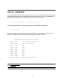
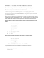
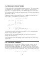
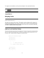
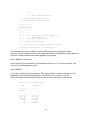
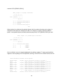
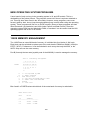
For register use and address, see the previous chaptes on the associated functions.
Go to chapter 13
Go to chapter 15
CHAPTER 15
Display Lists
[some of this file was lost...]
chip also has a memory scan counter. This register scans the display buffer for data to be
interpreted and displayed. Once loaded, the memory scan counter’s 4 most significant bits
are fixed. The result is that the memory scan counter cannot cross a 4K memory boundary
(i.e. $AFFF to $B000) without being reloaded.
DISPLAY LIST INSTRUCTIONS
There are three basic instructions in the display list. The type of instruction is determined by
bits 0,1,2 and 3 of an instruction byte. The other four bits give auxilliary parameters for the
instruction. Bit 7 always enables a display list interrupts (DLIs).
Display list instruction format
7 6 5 4 3 2 1 0
−−−−−−−−−−−−−−−−−
|I|n|n|n|0|0|0|0|
−−−−−−−−−−−−−−−−−
\
/ \
/
−−−
−−−−−−
|
|
|
0 = display blank lines
|
0−7 = number of blank lines (1−8)
7 6 5 4 3 2 1 0
−−−−−−−−−−−−−−−−−
|I|W| | |0|0|0|1|
−−−−−−−−−−−−−−−−−
|
\
/
74