1
GPM8F3232A
GPM8F3216A
GPM8F3208A
44/28/24 Pin 8-bit Microcontroller
with 32/16/8KB Flash
Preliminary
AUG. 03, 2012
Version 0.1
Generalplus Technology Inc. reserves the right to change this documentation without prior notice. Information provided by Generalplus Technology Inc. is
believed to be accurate and reliable. However, Generalplus Technology Inc. makes no warranty for any errors which may appear in this document. Contact
Generalplus Technology Inc. to obtain the latest version of device specifications before placing your order.
No responsibility is assumed by Generalplus
Technology Inc. for any infringement of patent or other rights of third parties which may result from its use.
In addition, Generalplus products are not
authorized for use as critical components in life support devices/systems or aviation devices/systems, where a malfunction or failure of the product may
reasonably be expected to result in significant injury to the user, without the express written approval of Generalplus.
Preliminary
GPM8F3232A/3216A/3208A
Table of Contents
PAGE
1. GENERAL DESCRIPTION.......................................................................................................................................................................... 5
2. FEATURES .................................................................................................................................................................................................. 5
3. BLOCK DIAGRAM ...................................................................................................................................................................................... 7
3.1. GPM8F3232A ..................................................................................................................................................................................... 7
3.2. GPM8F3216A ..................................................................................................................................................................................... 8
3.3. GPM8F3208A ..................................................................................................................................................................................... 9
4. SIGNAL DESCRIPTIONS ......................................................................................................................................................................... 10
4.1. PIN DESCRIPTIONS ............................................................................................................................................................................. 10
4.1.1. GPM8F3232A ......................................................................................................................................................................... 10
4.1.2. GPM8F3216A ..........................................................................................................................................................................11
4.1.3. GPM8F3208A ......................................................................................................................................................................... 12
4.2. PIN MAP ............................................................................................................................................................................................ 13
5. FUNCTIONAL DESCRIPTIONS................................................................................................................................................................ 15
5.1. CENTRAL PROCESSING UNIT ............................................................................................................................................................... 15
5.1.1. CPU Introduction..................................................................................................................................................................... 15
5.1.2. CPU Features ......................................................................................................................................................................... 15
5.1.3. Arithmetic Logic Unit (ALU)..................................................................................................................................................... 15
5.1.4. Accumulator A Register........................................................................................................................................................... 15
5.1.5. B Register ............................................................................................................................................................................... 15
5.1.6. Program Status Word (PSW) .................................................................................................................................................. 15
5.1.7. Program Counter (PC) ............................................................................................................................................................ 15
5.2. MEMORY ORGANIZATION ..................................................................................................................................................................... 16
5.2.1. Introduction ............................................................................................................................................................................. 16
5.2.2. Program Memory Allocation.................................................................................................................................................... 16
5.2.3. Data Memory Allocation .......................................................................................................................................................... 18
5.2.4. Memory Related SFR ............................................................................................................................................................. 19
5.2.4.1. Program Write Enable Bit .......................................................................................................................................... 19
5.2.4.2. Data Pointer Registers ............................................................................................................................................... 19
5.2.4.3. Stack Pointer.............................................................................................................................................................. 19
5.3. SPECIAL FUNCTION REGISTERS(SFR) ................................................................................................................................................. 22
5.4. CLOCK SOURCE .................................................................................................................................................................................. 25
5.5. POWER SAVING MODE ........................................................................................................................................................................ 27
5.5.1. Introduction ............................................................................................................................................................................. 27
5.5.2. IDLE Mode .............................................................................................................................................................................. 27
5.5.3. STOP Mode ............................................................................................................................................................................ 27
5.6. INTERRUPT SYSTEM ............................................................................................................................................................................ 29
5.6.1. Introduction ............................................................................................................................................................................. 29
5.7. RESET SOURCES ................................................................................................................................................................................ 34
5.7.1. Introduction ............................................................................................................................................................................. 34
5.7.2. Power-On Reset (POR) .......................................................................................................................................................... 34
5.7.3. Low Voltage Reset (LVR) ........................................................................................................................................................ 34
5.7.4. Pad Reset (PAD_RST)............................................................................................................................................................ 35
© Generalplus Technology Inc.
Proprietary & Confidential
2
AUG. 03, 2012
Preliminary Version: 0.1
Preliminary
GPM8F3232A/3216A/3208A
5.7.5. Watchdog Timer Reset (WDT_RST)....................................................................................................................................... 35
5.7.6. Other Reset Sources .............................................................................................................................................................. 35
5.8. I/O PORTS .......................................................................................................................................................................................... 40
5.8.1. Introduction ............................................................................................................................................................................. 40
5.9. TIMER MODULE................................................................................................................................................................................... 47
5.9.1. Introduction ............................................................................................................................................................................. 47
5.9.2. Timer 0/1 ................................................................................................................................................................................. 47
5.9.2.1.Timer 0: Mode 0 (13-Bit Timer/Counter) ..................................................................................................................... 50
5.9.2.2.Timer 0: Mode 1 (16-Bit Timer/Counter) ..................................................................................................................... 51
5.9.2.3.Timer 0: Mode 2 (8-bit Timer/Counter with Auto-reloadable Function) ....................................................................... 52
5.9.2.4.Timer 0: Mode 3 (Two 8-Bit Timers/Counters) ............................................................................................................ 53
5.9.2.5.Timer 1: Mode 0 (13-Bit Timer/Counter) ..................................................................................................................... 54
5.9.2.6.Timer 1: Mode 1 (16-Bit Timer/Counter) ..................................................................................................................... 55
5.9.2.7.Timer 1: Mode 2 (8-Bit Timer/Counter with Auto-reloadable Function)....................................................................... 56
5.9.2.8.Timer 1: Mode 3 .......................................................................................................................................................... 56
5.9.3. Timer 2 .................................................................................................................................................................................... 57
5.9.3.1.Timer Mode ................................................................................................................................................................. 57
5.9.3.2.Reload of Timer 2........................................................................................................................................................ 58
5.9.3.3.Compare Functions (PWM output) ............................................................................................................................. 59
5.9.3.4.Capture Functions....................................................................................................................................................... 60
5.9.3.5.Timer 2 Related Registers .......................................................................................................................................... 62
5.10. UART0 .............................................................................................................................................................................................. 66
5.10.1.
UART0: Mode 0 (Synchronous Shift Register)................................................................................................................... 66
5.10.2.
UART0: Mode 1 (8-Bit UART, Variable Baud Rate, Timer1 Clock Source) ........................................................................ 67
5.10.3.
UART0: Mode 2 (9-Bit UART, Fixed Baud Rate)................................................................................................................ 67
5.10.4.
UART0: Mode 3 (9-Bit UART, Variable Baud Rate, Timer1 Clock Source) ........................................................................ 67
5.10.5.
UART0 Related Registers .................................................................................................................................................. 67
5.11. SPI .................................................................................................................................................................................................... 70
5.12. ADC .................................................................................................................................................................................................. 73
5.12.1.
ADC Control ....................................................................................................................................................................... 73
5.13. BUILT-IN OP CIRCUITS ........................................................................................................................................................................ 76
5.14. AUDIO UNIT ........................................................................................................................................................................................ 77
5.15. ALPHABETICAL LIST OF INSTRUCTION SET ............................................................................................................................................ 80
5.15.1.
Arithmetic Operations ......................................................................................................................................................... 80
5.15.2.
Logic Operations ................................................................................................................................................................ 80
5.15.3.
Boolean Operations............................................................................................................................................................ 81
5.15.4.
Data Transfers .................................................................................................................................................................... 81
5.15.5.
Program Branches.............................................................................................................................................................. 83
6. ELECTRICAL CHARACTERISTICS......................................................................................................................................................... 84
6.1. ABSOLUTE MAXIMUM RATINGS ............................................................................................................................................................ 84
6.2. AC CHARACTERISTICS (TA = 25℃)...................................................................................................................................................... 84
6.3. DC CHARACTERISTICS (TA = 25℃)...................................................................................................................................................... 84
6.4. ADC CHARACTERISTICS (TA = 25℃) ................................................................................................................................................... 84
6.4.1. 12 bit Mode ............................................................................................................................................................................. 84
6.4.2. 8 bit Mode ............................................................................................................................................................................... 85
© Generalplus Technology Inc.
Proprietary & Confidential
3
AUG. 03, 2012
Preliminary Version: 0.1
Preliminary
GPM8F3232A/3216A/3208A
6.5. OP CHARACTERISTICS (TA = 25℃)...................................................................................................................................................... 85
7. PACKAGE INFORMATION ....................................................................................................................................................................... 86
7.1. ORDERING INFORMATION .................................................................................................................................................................... 86
7.2. PACKAGE INFORMATION ...................................................................................................................................................................... 86
8. DISCLAIMER............................................................................................................................................................................................. 89
9. REVISION HISTORY ................................................................................................................................................................................. 90
© Generalplus Technology Inc.
Proprietary & Confidential
4
AUG. 03, 2012
Preliminary Version: 0.1
Preliminary
GPM8F3232A/3216A/3208A
44/28/24 PIN 8-BIT MICROCONTROLLER WITH 32/16/8KB FLASH
1. GENERAL DESCRIPTION
The
GPM8F3232A/3216A/3208A
is
a
highly
− Software Reset (S/W_RST)
integrated
microcontroller which integrates a pipelined 1T 8051 CPU,
− Stop mode Reset (STOP_RST)
1K/512/256-byte XRAM, 256-byte IDM SRAM and 32/16/8K-byte
− Miss Clock Reset (MISS_CLK_RST)
program
Flash.
It
includes
34/24/20
− Flash Related Error Reset (FLASH_ERR_RST)
programmable
Programmable Watchdog Timer
multi-functional I/Os, Timer0/1/2, UART0, SPI (master), built-in OP,
audio and one up to 8-channel of 12-bit ADC for general-purpose
− A time-base generator
application.
− An event timer
It operates over a wide voltage range of 2.4V - 5.5V
with different clock sources.
management unit.
− System supervisor
It has two modes in power
I/O Ports
Moreover, there is one on-chip debug circuit
with two pins to facilitate full speed in-system debug.
− Max. 34/24/20 multifunction bi-directional I/Os
The detail
− Each incorporate with pull-up resistor, pull-down resistor,
is described in the following sections.
output high, output low or floating input, depending on
programmer’s settings on the corresponding registers
− I/O ports with 20mA current sink
2. FEATURES
− I/O ports with 8mA current drive
CPU
Two 16-bit Timer/Counter (Timer 0/1)
− High speed, high performance 1T 8051
− Timer mode with clock source selectable
z 100% software compatible with industry standard 8051
z Pipeline
RISC
architecture
enables
to
− Auto reload 8-bit timers
execute
− Externally gated event counters
instructions 10 times faster than standard 8051
One Powerful Timer 2 with 16-bit Compare/Capture Unit
z Up to 24.5MHz clock operation
− Timer mode with clock source selectable
Memories
− Auto-reload 16-bit timers
− 1K/512/256 bytes XRAM
− Externally gated event counters
− 256 bytes internal Data Memory (IDM) SRAM
− Event capturing
− 32/16/8K bytes Flash with high endurance
− Pulse width modulation and measurement
z Minimum 200,000 program/erase cycles
UART0
z Minimum 20 years data retention
− One synchronous mode
− Programming read only level for software security
− Three asynchronous modes
Clock Management
SPI (master mode)
− Internal oscillator: 24.5MHz±2% @ 2.4V~5.5V
− Programmable phase and polarity of master clock
− External clock input max 24.5MHz
− Programmable master SPI_CLK clock frequency
− Crystal input with 32768Hz or 1MHz~25MHz
− Max SPI clock: 6.125MHz (FOSC /4) @24.5MHz
Power Management
A/D Converter
− 1 STOP mode for power saving
− One 8-channel 8-bit resolution mode
− 1 IDLE mode for only peripheral operation
(GPM8F3232A/3216A)
Interrupt Management
− One 8-channel 12-bit resolution mode
− 14 interrupt sources(GPM8F3232A/3216A)
(GPM8F3232A/3216A)
− Up to 6 external interrupt sources(GPM8F3232A/3216A)
− One 6-channel 8-bit resolution mode (GPM8F3208A)
− 12 interrupt sources(GPM8F3208A)
− One 6-channel 12-bit resolution mode (GPM8F3208A)
− Up to 4 external interrupt sources(GPM8F3208A)
− Max conversion clock: 6.125MHz (FOSC /4) @24.5MHz
Reset Management
Built-in OP Circuit
− Power On Reset (POR)
Audio Module (available only in GPM8F3232A)
− Low Voltage Reset (LVR)
− 24KHz output or 32KHz output @24.5MHz
− Pad Reset (PAD_RST)
Debug Unit
− Watchdog Reset (WDT_RST)
© Generalplus Technology Inc.
Proprietary & Confidential
5
AUG. 03, 2012
Preliminary Version: 0.1
Preliminary
GPM8F3232A/3216A/3208A
Product Number
GPM8F3232A
GPM8F3216A
GPM8F3208A
Speed (MHz)
24.5
24.5
24.5
Operating Voltage (V)
2.4~5.5
2.4~5.5
2.4~5.5
Flash (Kbytes)
32
16
8
XRAM (bytes)
1K
512
256
IDM (bytes)
256
256
256
Timer
3
3
3
UART
1
1
1
SPI
1
1
1
12-bit ADC
8-channel
8-channel
6-channel
Built-in OP
Yes
Yes
Yes
IO
34
24
20
Package Type
LQFP44
SOP28
SOP24
© Generalplus Technology Inc.
Proprietary & Confidential
6
AUG. 03, 2012
Preliminary Version: 0.1
Preliminary
GPM8F3232A/3216A/3208A
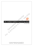
3. BLOCK DIAGRAM
3.1. GPM8F3232A
RESET/SCK
SYSCLK
2WIRE
WRITER /ICE
I/F
SRAM
256B
IDM I/F
ALU
XRAM
1KB
(max.)
EXTERNAL
DATA
MEMORY
I/F
SFR I/F
Flash
32KB
(max.)
FLASH
CONTROLLER
WATCHDOG
TIMER
GATE0
IMM023
44-LQFP
TIMERS
0/1
T0
GATE1
BUS(24.5MHz)
OPCODE
DECODER
IOSC
P42/SDA
RESET/SCK
POWER
MANAGEMENT
UNIT
T1
T2EX
TXD0
CAPTURE[3:0]
TIMER 2
UART 0
OP
MACRO
SPI
COMPARE[3:1]
P0[5:4]
P0[6]
INT[6:3]
INT[1:0]
P0[7:0]
ADC
MACRO
INTERRUPT
CONTROLLER
I/O Port
CONTROLLER
ADC
CONTROLLER
AUDIO
RXD0
SPITXD
SPIRXD
P0[7:0]
P1[5:1]
P2[7:0]
P3[7:0]
P4[4:0]
P3[7:6]
Figure 3-1 Block diagram of GPM8F3232A
© Generalplus Technology Inc.
Proprietary & Confidential
7
AUG. 03, 2012
Preliminary Version: 0.1
Preliminary
GPM8F3232A/3216A/3208A
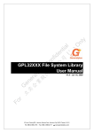
3.2. GPM8F3216A
RESET/SCK
SYSCLK
2WIRE
WRITER /ICE
I/F
SRAM
256B
IDM I/F
ALU
XRAM
512B
(max.)
EXTERNAL
DATA
MEMORY
I/F
SFR I/F
Flash
16KB
(max.)
FLASH
CONTROLLER
WATCHDOG
TIMER
IMM023
44-LQFP
TIMERS
0/1
P42/SDA
RESET/SCK
POWER
MANAGEMENT
UNIT
TXD0
CAPTURE[3:0]
COMPARE[3:2]
P0[5:4]
P0[6]
INT[6:3]
TIMER 2
UART 0
OP
MACRO
SPI
INTERRUPT
CONTROLLER
INT[1:0]
P0[7:0]
BUS(24.5MHz)
OPCODE
DECODER
IOSC
ADC
MACRO
I/O Port
CONTROLLER
RXD0
SPITXD
SPIRXD
P0[7:0]
P1[5:2]
P2[6:1]
P3[3:0]
P4[2:1]
ADC
CONTROLLER
Figure 3-2 Block diagram of GPM8F3216A
© Generalplus Technology Inc.
Proprietary & Confidential
8
AUG. 03, 2012
Preliminary Version: 0.1
Preliminary
GPM8F3232A/3216A/3208A
3.3. GPM8F3208A
RESET/SCK
SYSCLK
2WIRE
WRITER /ICE
I/F
SRAM
256B
IDM I/F
ALU
XRAM
256B
(max.)
EXTERNAL
DATA
MEMORY
I/F
SFR I/F
Flash
8KB
(max.)
FLASH
CONTROLLER
WATCHDOG
TIMER
IMM023
44-LQFP
TIMERS
0/1
CAPTURE[3]
CAPTURE[1:0]
BUS(24.5MHz)
OPCODE
DECODER
IOSC
RESET/SCK
POWER
MANAGEMENT
UNIT
TXD0
TIMER 2
UART 0
OP
MACRO
SPI
COMPARE[3:2]
P0[5:4]
P0[6]
INT[6]
INTERRUPT
CONTROLLER
INT[4:3]
INT[0]
P0[7:2]
P42/SDA
ADC
MACRO
I/O Port
CONTROLLER
RXD0
SPITXD
SPIRXD
P0[7:2]
P1[5],P1[3:2]
P2[6:1]
P3[2:0]
P4[2:1]
ADC
CONTROLLER
Figure 3-3 Block diagram of GPM8F3208A
© Generalplus Technology Inc.
Proprietary & Confidential
9
AUG. 03, 2012
Preliminary Version: 0.1
Preliminary
GPM8F3232A/3216A/3208A
4. SIGNAL DESCRIPTIONS
4.1. Pin Descriptions
4.1.1. GPM8F3232A
Type: I = Input, O = Output, S = Supply
Pin Name
LQFP44
Type
Description
P14
1
I/O
Port 1 bit 4 / INT5 / CAPTURE2
P15
2
I/O
Port 1 bit 5 / INT6 / CAPTURE3
RESET
3
I
RESET signal, high active / SCK(2 wire serial bus clock input line)
NC
4
P30
5
I/O
Port 3 bit 0 / RXD0
P31
6
I/O
Port 3 bit 1 / TXD0
P32
7
I/O
Port 3 bit 2 / INT0
P33
8
I/O
Port 3 bit 3 / INT1
P34
9
I/O
Port 3 bit 4 / T0(Timer 0 input)
P35
10
I/O
Port 3 bit 5 / T1(Timer 1 input)
NC
11
P36
12
I/O
Port 3 bit 6 / GATE0(Timer 0 gate) / AUDIO_N
P37
13
I/O
Port 3 bit 7 / GATE1(Timer 1 gate) / AUDIO_P
VSS
14
S
P27
15
I/O
Port 2 bit 7
P20
16
I/O
Port 2 bit 0
P21
17
I/O
Port 2 bit 1
P22
18
I/O
Port 2 bit 2
P23
19
I/O
Port 2 bit 3
P24
20
I/O
Port 2 bit 4
NC
21
NC
22
Ground
P25
23
I/O
Port 2 bit 5 / XTI
P26
24
I/O
Port 2 bit 6 / XTO
VREG
25
S
P44
26
I/O
Port 4 bit 4
P43
27
I/O
Port 4 bit 3
Regulator output, needs 2.2uF Cap.
P42
28
I/O
Port 4 bit 2 / SDA(2 wire serial bus data input / output line)
P41
29
I/O
Port 4 bit 1
P40
30
I/O
Port 4 bit 0
NC
31
P07
32
I/O
Port 0 bit 7 / AN7(ADC channel 7 input) / SPI0_RX
P06
33
I/O
Port 0 bit 6 / AN6(ADC channel 6 input) / SPI0_TX / OP_OUT
P05
34
I/O
Port 0 bit 5 / AN5(ADC channel 5 input) / SPI0_CLK / OP V-
P04
35
I/O
Port 0 bit 4 / AN4(ADC channel 4 input) / SPI0_CSB / OP V+
P03
36
I/O
Port 0 bit 3 / AN3(ADC channel 3 input)
P02
37
I/O
Port 0 bit 2 / AN2(ADC channel 2 input)
P01
38
I/O
Port 0 bit 1 / AN1(ADC channel 1 input)
P00
39
I/O
VCC
40
S
NC
41
© Generalplus Technology Inc.
Proprietary & Confidential
Port 0 bit 0 / AN0(ADC channel 0 input)
Power 5V input
10
AUG. 03, 2012
Preliminary Version: 0.1
Preliminary
GPM8F3232A/3216A/3208A
Pin Name
LQFP44
Type
P11
42
I/O
Port 1 bit 1 / T2EX / COMPARE1(PWM1)
Description
P12
43
I/O
Port 1 bit 2 / INT3 / CAPTURE0 / COMPARE2(PWM2)
P13
44
I/O
Port 1 bit 3 / INT4 / CAPTURE1 / COMPARE3(PWM3)
4.1.2. GPM8F3216A
Type: I = Input, O = Output, S = Supply
Pin Name
SOP28
Type
Description
P00
1
I/O
VCC
2
S
P12
3
I/O
Port 1 bit 2 / INT3 / CAPTURE0 / COMPARE2(PWM2)
P13
4
I/O
Port 1 bit 3 / INT4 / CAPTURE1 / COMPARE3(PWM3)
P14
5
I/O
Port 1 bit 4 / INT5 / CAPTURE2
P15
6
I/O
Port 1 bit 5 / INT6 / CAPTURE3
RESET
7
I
P30
8
I/O
Port 3 bit 0 / RXD0
P31
9
I/O
Port 3 bit 1 / TXD0
P32
10
I/O
Port 3 bit 2 / INT0
Port 0 bit 0 / AN0(ADC channel 0 input)
Power 5V input
RESET signal, high active / SCK(2 wire serial bus clock input line)
P33
11
I/O
VSS
12
S
P21
13
I/O
Port 2 bit 1
P22
14
I/O
Port 2 bit 2
P23
15
I/O
Port 2 bit 3
P24
16
I/O
Port 2 bit 4
P25
17
I/O
Port 2 bit 5 / XTI
P26
18
I/O
Port 2 bit 6 / XTO
VREG
19
S
P42
20
I/O
Port 3 bit 3 / INT1
Ground
Regulator output, needs 2.2uF Cap.
Port 4 bit 2 / SDA(2 wire serial bus data input / output line)
P41
21
I/O
Port 4 bit 1
P07
22
I/O
Port 0 bit 7 / AN7(ADC channel 7 input) / SPI0_RX
P06
23
I/O
Port 0 bit 6 / AN6(ADC channel 6 input) / SPI0_TX / OP_OUT
P05
24
I/O
Port 0 bit 5 / AN5(ADC channel 5 input) / SPI0_CLK / OP V-
P04
25
I/O
Port 0 bit 4 / AN4(ADC channel 4 input) / SPI0_CSB / OP V+
P03
26
I/O
Port 0 bit 3 / AN3(ADC channel 3 input)
P02
27
I/O
Port 0 bit 2 / AN2(ADC channel 2 input)
P01
28
I/O
Port 0 bit 1 / AN1(ADC channel 1 input)
© Generalplus Technology Inc.
Proprietary & Confidential
11
AUG. 03, 2012
Preliminary Version: 0.1
Preliminary
GPM8F3232A/3216A/3208A
4.1.3. GPM8F3208A
Type: I = Input, O = Output, S = Supply
Pin Name
SOP24
Type
P02
1
I/O
Description
VCC
2
S
P12
3
I/O
Port 1 bit 2 / INT3 / CAPTURE0 / COMPARE2(PWM2)
P13
4
I/O
Port 1 bit 3 / INT4 / CAPTURE1 / COMPARE3(PWM3)
P15
5
I/O
Port 1 bit 5 / INT6 / CAPTURE3
Port 0 bit 2 / AN2(ADC channel 2 input)
Power 5V input
RESET
6
I
P30
7
I/O
Port 3 bit 0 / RXD0
P31
8
I/O
Port 3 bit 1 / TXD0
P32
9
I/O
Port 3 bit 2 / INT0
VSS
10
S
P21
11
I/O
Port 2 bit 1
P22
12
I/O
Port 2 bit 2
P23
13
I/O
Port 2 bit 3
P24
14
I/O
Port 2 bit 4
P25
15
I/O
Port 2 bit 5 / XTI
P26
16
I/O
VREG
17
S
P42
18
I/O
RESET signal, high active / SCK(2 wire serial bus clock input line)
Ground
Port 2 bit 6 / XTO
Regulator output, needs 2.2uF Cap.
Port 4 bit 2 / SDA(2 wire serial bus data input/output line)
P41
19
I/O
Port 4 bit 1
P07
20
I/O
Port 0 bit 7 / AN7(ADC channel 7 input) / SPI0_RX
P06
21
I/O
Port 0 bit 6 / AN6(ADC channel 6 input) / SPI0_TX / OP_OUT
P05
22
I/O
Port 0 bit 5 / AN5(ADC channel 5 input) / SPI0_CLK / OP V-
P04
23
I/O
Port 0 bit 4 / AN4(ADC channel 4 input) / SPI0_CSB / OP V+
P03
24
I/O
Port 0 bit 3 / AN3(ADC channel 3 input)
© Generalplus Technology Inc.
Proprietary & Confidential
12
AUG. 03, 2012
Preliminary Version: 0.1
Preliminary
GPM8F3232A/3216A/3208A
4.2. PIN Map
Package Pin Sequence - LQFP 44 Package Top View
(AN1) P01
(AN2) P02
(AN3) P03
(AN5/SPI0_CLK/OP V-) P05
(AN4/SPI0_CSB/OP V+) P04
40
39
38
36
37
34
35
P23
NC
NC
P24
P21
22
21
20
P20
P22
17
P27
19
16
18
15
13
33 32 31 30 29 28 27 26 25 24 23
(AN0) P00
41
P36 (GATE0/AUDIO_N)
VSS
P37 (GATE1/AUDIO_P)
Proprietary & Confidential
NC
GPM8F3732A
14
13
12
© Generalplus Technology Inc.
VCC
44
42
43
9 10 11
NC
(INT4/CAPTURE1/COMPARE3) P13
5 6
(T0) P34
GPM8F3232A
7 8
(RXD0) P30
(TXD0) P31
(INT0) P32
(INT1) P33
(T1) P35
(T2EX/COMPARE1) P11
(INT3/CAPTURE0/COMPARE2) P12
NC
1 2 3 4
(INT5/CAPTURE2) P14
(INT6/CAPTURE3) P15
(SCK) RESET
P06 (AN6/SPI0_TX/OP_OUT)
P07 (AN7/SPI0_RX)
NC
P40
P41
P42 (SDA)
P43
P44
VREG
P26 (XTO)
P25 (XTI)
AUG. 03, 2012
Preliminary Version: 0.1
Preliminary
GPM8F3232A/3216A/3208A
Package Pin Sequence – SOP28 Package Top View
P00/AN0
1
28
P01/AN1
VCC
2
27
P02/AN2
P12/INT3/CAPTURE0/COMPARE2
3
26
P03/AN3
P13/INT4/CAPTURE1/COMPARE3
4
25
P04/AN4/SPI0_CSB/OP V+
P14/INT5
5
24
P05/AN5/SPI0_CLK//OP V-
P15/INT6
6
23
P06/AN6/SPI0_TX/OP_OUT
RESET/SCK
7
22
P07/AN7/SPI0_RX
P30/RXD
8
21
P41
P31/TXD
9
20
P42/SDA
P32/INT0
10
19
VREG
P33/INT1
11
18
P26/XTO
VSS
12
17
P25/XTI
P21
13
16
P24
P22
14
15
P23
GPM8F3216A
GPM8F3716A
Package Pin Sequence – SOP24 Package Top View
P02/AN2
1
24
P03/AN2
VCC
2
23
P04/AN4/SPI0_CSB/OP V+
P12/INT3/CAPTURE0/COMPARE2
3
22
P05/AN5/SPI0_CLK//OP V-
P13/INT4/CAPTURE1/COMPARE3
4
21
P06/AN6/SPI0_TX/OP_OUT
P15/CAPTURE3
5
20
P07/AN7/SPI0_RX
RESET/SCK
6
19
P41
P30/RXD
7
18
P42/SDA
P31/TXD
8
17
VREG
P32/INT0
9
16
P26/XTO
VSS
10
15
P25/XTI
P21
11
14
P24
P22
12
13
P23
© Generalplus Technology Inc.
Proprietary & Confidential
GPM8F3708A
GPM8F3208A
14
AUG. 03, 2012
Preliminary Version: 0.1
Preliminary
GPM8F3232A/3216A/3208A
5. FUNCTIONAL DESCRIPTIONS
5.1. Central Processing Unit
instruction execution.
5.1.1. CPU Introduction
subtraction, multiplication and division.
compare.
Pipelined architecture enables the CPU 10 times
faster than standard architecture.
Additional operations are
such as increment, decrement, BCD-decimal-add-adjust and
The CPU is an ultra high performance, high speed embedded
microcontroller.
Typical arithmetic operations are addition,
Within logic unit, operation such as AND, OR,
Exclusive OR, complement and rotation are performed.
This performance can also be
exploited to great advantage in low power application where the
complement, jump-if-not-set, jump-if-set-and-clear and move
core can be clocked over ten times slower than original
to/from carry.
implementation for no performance penalty.
5.1.4. Accumulator A Register
5.1.2. CPU Features
The accumulation is the 8-bit general-purpose register, which can
100 % software compatible with industry 8051
be operated with data transfer, temporary saving, condition
24 times faster multiplication
judgment, etc.
12 times faster addition
5.1.5. B Register
The CPU is fully compatible with industry standard 8051
microcontroller, maintaining all instruction mnemonics and binary
The B register is used during multiply and divide operations.
compatibility.
other cases, it may be used as normal SFR.
It
The
Boolean processor performs the bit operations as set, clear,
incorporates
some
great
architectural
In
enhancements, allowing the CPU instructions execution with high
5.1.6. Program Status Word (PSW)
performance and high speed.
The PSW contains several bits that reflect the current state of the
CPU which is similar to the flag-register of general CPU.
The arithmetic section of the processor performs extensive data
manipulation and is comprised of an 8-bit arithmetic logic unit
(ALU), an ACC(0xE0) register, B(0xF0) register and PSW(0xD0)
5.1.7. Program Counter (PC)
register.
The program counter is a 16-bit wide register.
8-bit registers which are PCH and PCL.
It consists of two
This register indicates
5.1.3. Arithmetic Logic Unit (ALU)
the address of next instruction to be executed.
The ALU performs the arithmetic and logic operations during one
content of 0x0000 is stored into program counter.
ACC
Bit
Address: 0xE0
7
6
5
Accumulator A Register
4
Function
Default
In Reset state, the
3
2
1
0
0
0
0
0
ACC[7:0]
0
0
0
0
Bit
Function
Type
Description
7:0
ACC[7:0]
R/W
Accumulator A
Condition
Table 5-1 The ACC register
B
Address: 0xF0
Bit
7
6
5
B Register
4
Function
Default
3
2
1
0
0
0
0
0
B[7:0]
0
0
0
0
Bit
Function
Type
Description
7:0
B[7:0]
R/W
B
Condition
Table 5-2 The B register
© Generalplus Technology Inc.
Proprietary & Confidential
15
AUG. 03, 2012
Preliminary Version: 0.1
Preliminary
GPM8F3232A/3216A/3208A
PSW
Address: 0xD0
Bit
Function
7
6
5
4
3
2
1
0
CY
AC
F0
RS1
RS0
OV
F1
P
0
0
0
0
0
0
0
0
Default
Bit
Program Status Word Register
Function
Type
Description
Condition
7
CY
R/W
Carry flag
6
AC
R/W
Auxiliary carry flag
5
F0
R/W
General purpose flag 0
4:3
RS[1:0]
R/W
Register bank selection bits
RS[1:0]
Function Description
00
Bank 0, data address 0x00-0x07
01
Bank 1, data address 0x08-0x0F
10
Bank 2, data address 0x10-0x17
11
Bank 3, data address 0x18-0x1F
2
OV
R/W
Overflow flag
1
F1
R/W
General purpose flag 1
0
P
R/W
Parity flag
Table 5-3 The PSW register
5.2. Memory Organization
5.2.1. Introduction
‘0’, the whole chip memory is protected and any page erase or
The GPM8F3232A/3216A/3208A has three separated address
program by two wire serial interface is not allowed.
spaces for program memory and data memory.
thing user can do is to erase whole chip.
The program
Figure 5-1 shows the
program memory map of 32KB/16KB/8KB Flash.
memory is on-chip, re-programmable Flash memory and contains
up to 32/16/8K bytes spaces.
The only
The data memory is divided into
1K/512/256 bytes of external RAM, 256 bytes IDM with 128 bytes
After each reset, CPU starts execution in the program memory at
of SFR which can be read and written.
The upper IDM and SFR
location 0x0000.
Each interrupt has its own start address for
use the same access address in different access ways which are
service routine.
The Flash memory can be programmed
described in Figure 5-2.
in-system, through the SCK/SDA interface or by software using the
MOVX instruction when PWE= 1.
code in the programming guide for the procedure of write and
5.2.2. Program Memory Allocation
erase operations.
The program memory allocation is divided into two parts, including
code area and last page.
programmed.
The address
area
and
the
address
space
without data polling to determine the end of the write and erase
between
operation.
0x7C00/0x3C00/0x1C00 and 0x7FFF/0x3FFF/0x1FFF is called
LAST_PAGE which cannot be erased by software.
constants storage.
It reserves for
For
The last address 0x7FFF/0x3FFF/0x1FFF is
CONFIG_BYTE [0].
security
consideration,
user
can
set
the
area that avoids inadvertently erased or written by software, the
This CONFIG_BYTE value can be read from
CONFIG_BYTE register(0xB7).
software
programmable Flash level by FL_LEVEL register to limit the code
used for CONFIG_BYTE whose definition of each bit is described
in Table 5-4.
The write and erase operations are executed by
using Pseudo-idle mode to be automatically timed by hardware
space between 0x0000 and 0x7BFF/0x3BFF/0x1BFF is used for
code
Therefore, flash
data would typically be erased (set to 0xFF) before being
It begins at address 0x0000
and ends at address 0x7FFF/0x3FFF/0x1FFF.
Flash data cannot be programmed from a ‘0’ to
a ‘1’, and only erase operation can realize it.
The GPM8F3232A/3216A/3208A
implements 32/16/8KB memory size.
User can refer to the example
protected region is called READONLY_PAGE.
User can lock the whole chip by
If CONFIG_BYTE [0] is programmed to be
© Generalplus Technology Inc.
Proprietary & Confidential
16
AUG. 03, 2012
Preliminary Version: 0.1
Preliminary
GPM8F3232A/3216A/3208A
CONFIG_BYTE
CONFIG_BYTE
0x7FFF(32KB)
CONFIG_BYTE
0x3FFF(16KB)
LAST_PAGE
LAST_PAGE
0x1FFF(8KB)
LAST_PAGE
0x3C00(15KB)
0x7C00(31KB)
0x1C00(7KB)
Code Area
Code Area
Code Area
0x0000(0KB)
0x0000(0KB)
GPM8F3732A
GPM8F3232A
0x0000(0KB)
GPM8F3716A
GPM8F3216A
GPM8F3708A
GPM8F3208A
Figure 5-1 Program memory organization
CONFIG_BYTE
Address: 0xB7
CONFIG_BYTE Register
Bit
7
6
5
4
3
2
1
0
Function
--
--
LVRVSEL
--
--
--
IOSEL
CODE Lock
Default
1
1
1
1
1
1
1
1
Bit
Function
Type
7:6
--
R
5
LVRVSEL
R
Description
Condition
Reserved
LVR voltage level selection
0: 3.9V
1: 2.2V
4:2
--
R
IOSEL
R
CODE Lock
R
Reserved
1
IO initial state selection bit
0: Input pull high
1: floating
0
0 : CODE is locked;
1 : CODE is unlocked
Table 5-4 The CONFIG_BYTE register
FL_LEVEL
Address: 0xED
Bit
7
6
Function
--
--
Default
0
0
5
Flash Level Register
4
3
2
0
0
0
0
Function
Type
Description
7:6
--
R/W
Reserved
5:0
FLASH_LEVEL[5:0]
R/W
FLASH_LEVEL, it determines how many 1K pages are read only
Proprietary & Confidential
0
0
0
FLASH_LEVEL[5:0]
Bit
© Generalplus Technology Inc.
1
Condition
FLASH_LEVEL
Note
0
no page is read only
1
address < 0x400 is read only
2
address < 0x800 is read only
3
address < 0xC00 is read only
4
address < 0x1000 is read only
5
address < 0x1400 is read only
6
address < 0x1800 is read only
17
AUG. 03, 2012
Preliminary Version: 0.1
Preliminary
GPM8F3232A/3216A/3208A
Bit
Function
Type
5:0
FLASH_LEVEL[5:0]
R/W
Description
Condition
7
address < 0x1C00 is read only
8
address < 0x2000 is read only
9
address < 0x2400 is read only
10
address < 0x2800 is read only
11
address < 0x2C00 is read only
12
address < 0x3000 is read only
13
address < 0x3400 is read only
14
address < 0x3800 is read only
15
address < 0x3C00 is read only
16
address < 0x4000 is read only
17
address < 0x4400 is read only
18
address < 0x4800 is read only
19
address < 0x4C00 is read only
20
address < 0x5000 is read only
21
address < 0x5400 is read only
22
address < 0x5800 is read only
23
address < 0x5C00 is read only
24
address < 0x6000 is read only
25
address < 0x6400 is read only
26
address < 0x6800 is read only
27
address < 0x6C00 is read only
28
address < 0x7000 is read only
29
address < 0x7400 is read only
30
address < 0x7800 is read only
31
address < 0x7C00 is read only
≧32
address < 0x7FFF is read only
Note 1. Only FLASH_LEVEL[5:0] is useful in GPM8F3232A
Note 2. Only FLASH_LEVEL[4:0] is useful in GPM8F3216A
Note 3. Only FLASH_LEVEL[3:0] is useful in GPM8F3208A
Table 5-5 The FL_LEVEL register
5.2.3. Data Memory Allocation
Data
memory
address
allocations
on
GPM8F3232A/3216A/3208A are divided into two parts.
the
be utilized freely by user.
The first
The last 128 bytes of data memory can
be used by different addressing modes.
With the indirect
part is 1K/512/256 bytes of external RAM and the second one is
addressing mode, address from 0x80 to 0xFF shared with stack
256 byte IDM as shown in Figure 5-2.
space is addressed.
The lowest internal data
With the direct addressing mode, the SFR
memory (IDM) consists of four register banks with eight registers
addressing from 0x80 to 0xFF is accessed.
each.
map is shown in Table 5-6.
A bit addressable segment with 128 bits (16 bytes) begins
at 0x20.
The SFR memory
The address from 0x30 to 0x7F is not defined and can
© Generalplus Technology Inc.
Proprietary & Confidential
18
AUG. 03, 2012
Preliminary Version: 0.1
Preliminary
GPM8F3232A/3216A/3208A
SFR
Special Function
Registers
(direct addressing)
Upper Internal RAM
shared with Stack
space
(indirect addressing)
XRAM
0xFF
0x80
Lower Internal RAM shared with Stack space
(direct & indirect addressing)
0x30
Bit addressable area
0x20
4 banks, R0-R7 each
XRAM: 1KB(GPM8F3232A)
1KB(GPM8F3732A)
512B(GPM8F3716A)
512B(GPM8F3216A)
256B(GPM8F3708A)
256B(GPM8F3208A)
0x00
IDM:256B and SFR: 128B
Figure 5-2 Data memory organization
Note1: Black: standard 8051 register; gray: additional register;
0xF8
EIP
IOSCCON
IOSCT0
IOSCT1
SPICON
0xF0
B
ADCON
ADCFG
ADAEN
0xE8
EIE
TA
0xE0
ACC
0xD8
WDCON
0xD0
PSW
0xC8
T2CON
T2IF
0xC0
0xB8
SPITXD
SPIRXD
ADOL
ADOH
ADLB
FLASHCON
FL_LEVEL
ADUB
KEYCODE
CRCL
CRCH
TL2
TH2
CCEN
CCL1
CCH1
CCL2
CCH2
CCL3
CCH3
AUDBUF
IP
0xB0
P3
AUDCON
0xA8
IE
OPCON
0xA0
P2
0x98
0x90
WKUEN
CONFIG_BYTE
SRCON
SYSCON0
SYSCON1
P4
P3_PU
P3_PD
P4_PU
P4_PD
FLASHERRF
SYSCON2
SCON0
SBUF0
P0_PU
P0_PD
P1_PU
P1_PD
P2_PU
P2_PD
P1
EIF
BIP
BIF
0x88
TCON
TMOD
TL0
TL1
TH0
TH1
CKCON
RSTCON
0x80
P0
SP
DPL0
DPH0
DPL1
DPH1
DPS
PCON
0/8
1/9
2/A
3/B
4/C
5/D
6/E
7/F
RSTSTS
Table 5-6 SFR memory map
5.2.4. Memory Related SFR
5.2.4.2. Data Pointer Registers
The following sub-sections describe program, external and internal
Dual data pointer registers are implemented to speed up data
memories related SFRs of 8051 core and their functionality.
block copying.
For
DPTR0 and DPTR1 are located in four SFR
other information about standard SFRs, please refer to appropriate
addresses.
peripheral section.
If SEL=0 then DPTR0 is selected otherwise DPTR1.
5.2.4.1. Program Write Enable Bit
5.2.4.3. Stack Pointer
The Program Write Enable (PWE) bit, located in PCON register bit
The 8051 has 8-bit stack pointer called SP (0x81) located in the
4, is used during MOVX instructions.
internal RAM space.
When PWE bit is set to
Active DPTR register is selected by SEL bit (DPS[0]).
It is incremented before data is stored
logic 1, the MOVX @DPTR, An instruction writes data located in
during PUSH and CALL execution and decremented after data is
accumulator register into program memory addressed by DPTR
popped during POP, RET and RETI execution.
register.
it always points to the last valid stack byte.
Program memory can be read by MOVC only regardless
as any other SFRs.
of PWE bit.
In the other words,
The SP is accessed
Figure 5-3 shows an example when PUSH A
is executed and Figure 5-4 shows an example when POP PSW is
executed.
© Generalplus Technology Inc.
Proprietary & Confidential
19
AUG. 03, 2012
Preliminary Version: 0.1
Preliminary
GPM8F3232A/3216A/3208A
SP
SP
08H
07H
ACC
38H
08H
21H
07H
ACC
23H
08H
21H
07H
23H
23H
After execution
Before execution
Figure 5-3 Stack byte order for PUSH A instruction
SP
SP
07H
08H
PSW
65H
08H
21H
07H
PSW
65H
08H
21H
07H
65H
23H
After execution
Before execution
Figure 5-4 Stack byte order for POP PSW instruction
PCON
Bit
Function
Default
Address: 0x87
Power Configuration Register
7
6
5
4
3
2
1
0
SMOD0
--
CPU_IDLE
PWE
STOP_RST_EN
--
STOP
--
0
0
0
0
0
0
0
0
Bit
Function
Type
Description
Condition
7
SMOD0
R/W
UART0 double baud rate bit when clocked by Timer1
6
--
R/W
Reserved
5
CPU_IDLE
R/W
IDLE mode enable bit
0: IDLE mode disabled ;
1: IDLE mode entered
4
PWE
R/W
Program Write Enable (PWE)
0: Disable Flash write activity during MOVX instruction
1: Enable Flash write activity during MOVX instruction
3
STOP_RST_EN
R/W
Wakeup state selection bit
0: Next instruction state after wakeup
1: Reset state afer wakeup
2
--
R/W
1
STOP
R/W
Reserved
STOP mode enable bit
0: Disabled
1: Enabled
0
--
R/W
Reserved
Table 5-7 The PCON register
© Generalplus Technology Inc.
Proprietary & Confidential
20
AUG. 03, 2012
Preliminary Version: 0.1
Preliminary
GPM8F3232A/3216A/3208A
DPH0
Bit
Address: 0x83
Data Pointer Register - high byte
7
6
5
4
0
0
0
0
3
Function
Default
2
1
0
0
0
0
DPTR0[15:8]
0
Bit
Function
Type
Description
Condition
7:0
DPTR0[15:8]
R/W
Data pointer register DPTR0 - high byte
Table 5-8 The DPH0 register
DPL0
Bit
Address: 0x82
7
6
5
Data Pointer Register - low byte
4
3
Function
Default
2
1
0
0
0
0
DPTR0[7:0]
0
0
0
0
0
Bit
Function
Type
Description
Condition
7:0
DPTR0[7:0]
R/W
Data pointer register DPTR0 - low byte
Table 5-9 The DPL0 register
DPH1
Bit
Address: 0x85
7
6
5
Data Pointer 1 Register - high byte
4
3
Function
Default
2
1
0
0
0
0
DPTR1[15:8]
0
0
0
0
0
Bit
Function
Type
Description
Condition
7:0
DPTR1[15:8]
R/W
Data pointer 1 register DPTR1 - high byte
Table 5-10 The DPH1 register
DPL1
Bit
Address: 0x84
Data Pointer 1 Register - low byte
7
6
5
4
0
0
0
0
3
Function
Default
2
1
0
0
0
0
DPTR0[7:0]
0
Bit
Function
Type
Description
Condition
7:0
DPTR1[7:0]
R/W
Data pointer 1 register DPTR1 - low byte
Table 5-11 The DPL1 register
DPS
Bit
Function
Default
Address: 0x86
Data Pointer Select Register
7
6
5
4
3
2
1
0
ID1
ID0
TSL
--
--
--
--
SEL
0
0
0
0
0
0
0
0
© Generalplus Technology Inc.
Proprietary & Confidential
21
AUG. 03, 2012
Preliminary Version: 0.1
Preliminary
GPM8F3232A/3216A/3208A
Bit
Function
Type
7:6
ID[1:0]
R/W
5
TSL
R/W
Description
Condition
Increment/decrement function select.
See Table 5-13
Toggle select enable bit
0: DPTR related instructions do not affect state of SEL bit
1: DPTR related instructions to toggle the SEL bit
4:1
--
R/W
0
SEL
R/W
Reserved
Active data pointer select bit
See Table 5-13
Table 5-12 The DPS register
ID1
ID0
SEL=0
SEL=1
0
0
INC DPTR0
INC DPTR1
0
1
DEC DPTR0
INC DPTR1
1
0
INC DPTR0
DEC DPTR1
1
1
DEC DPTR0
DEC DPTR1
Table 5-13 DPTR0/DPTR1 operations
SP
Address: 0x81
Bit
Stack Pointer Register
7
6
5
4
0
0
0
0
Function
3
2
1
0
0
1
1
1
SP[7:0]
Default
Bit
Function
Type
Description
7:0
SP[7:0]
R/W
Stack pointer
Condition
Table 5-14 The SP register
5.3. Special Function Registers(SFR)
GPM8F3232A/3216A/3208A has up to 84 control registers for
effect on corresponding bits.
special function registers.
that KEYCODE register must be written with correct key codes, in
All of the SFRs are used by MCU and
Some SFRs have key code design
peripheral function block for controlling the desired operation.
sequence, before writing a value to it for software security.
Some of the SFRs contain control and status bits for peripheral
following table shows the summary of the SFRs.
module such as Timer unit, Interrupt control unit, etc.
information of each SFRs are explained in each peripheral section.
Some of
The
The detailed
bits in SFRs are read only, so write to those bits don't have any
Key
Reset
Addr
Function
0x80
P0
0xFF
Port 0
0x81
SP
0x07
Stack Pointer
0x82
DPL0
0x00
Data pointer register DPTR0 - low byte
0x83
DPH0
0x00
Data pointer register DPTR0 - high byte
0x84
DPL1
0x00
Data pointer register DPTR1 - low byte
0x85
DPH1
0x00
0x86
DPS
0x00
Code Value
© Generalplus Technology Inc.
Proprietary & Confidential
7
6
5
4
3
2
1
0
--
SEL
Data pointer register DPTR1 - high byte
ID1
ID0
TSL
22
--
--
--
AUG. 03, 2012
Preliminary Version: 0.1
Preliminary
GPM8F3232A/3216A/3208A
Addr
Function
0x87
PCON
0x88
Key
Reset
7
6
0x00
SMOD0
--
TCON
0x00
TF1
TR1
TF0
TR0
0x89
TMOD
0x00
GATE1
CT1
M11
M10
0x8A
TL0
0x00
Timer 0 Load value – low byte
0x8B
TL1
0x00
Timer 1 Load value – low byte
0x8C
TH0
0x00
Timer 0 Load value – high byte
0x8D
TH1
0x00
Timer 1 Load value – high byte
0x8E
CKCON
0x01
0x8F
RSTCON
Code Value
4F,72,
7A
0x10
WD1
WD0
CB_P_
ENB
5
4
CPU_
IDLE
3
2
1
0
--
STOP
--
IE1
IT1
IE0
IT0
GATE0
CT0
M01
M00
--
--
--
STOP_
PWE
RST_EN
--
T1M
T0M
LP_E_
FLASH_
XADDR_
ENB
FLOW_ ENB
ENB
--
--
INT6F
MISS_
STOP_
FLASH_
CLK_RST
RST
ERR_RST
--
--
PAUDIO
PADC
--
0x90
P1
0xff
0x91
EIF
0x00
--
0x94
RSTSTS
0x00
--
0x96
BIP
0x00
--
0x97
BIF
0x00
--
--
--
AUDIOF
ADCF
0x98
SCON0
0x00
SM00
SM01
SM02
REN0
TB08
0x99
SBUF0
0x00
0x9A
P0_PU
0xFF
P07_PU
P06_PU
P05_PU
P04_PU
P03_PU
0x9B
P0_PD
0x00
P07_PD
P06_PD
P05_PD
P04_PD
P03_PD
0x9C
P1_PU
0xFF
P17_PU
P16_PU
P15_PU
P14_PU
P13_PU
CHIP_E_ MISS_CLK_ FLASH_ERR
ENB
ENB
_ ENB
INT4F
INT3F
--
Port 1
INT5F
S/W_RST WDT_RST LVR_RST RAD_RST
--
--
PMERR
--
--
MERRF
RB08
TI0
RI0
P02_PU
P01_PU
P00_PU
P02_PD
P01_PD
P00_PD
P12_PU
P11_PU
P10_PU
UART 0 buffer
0x9D
P1_PD
0x00
P17_PD
P16_PD
P15_PD
P14_PD
P13_PD
P12_PD
P11_PD
P10_PD
0x9E
P2_PU
0xFF
P27_PU
P26_PU
P25_PU
P24_PU
P23_PU
P22_PU
P21_PU
P20_PU
P27_PD
P26_PD
P25_PD
P24_PD
P23_PD
P22_PD
P21_PD
P20_PD
0x9F
P2_PD
0x00
0xA0
P2
0xFF
Port 2
0xA1
P4
0xFF
Port 4
0xA2
P3_PU
0xFF
P37_PU
P36_PU
P35_PU
P34_PU
P33_PU
P32_PU
P31_PU
P30_PU
0xA3
P3_PD
0x00
P37_PD
P36_PD
P35_PD
P34_PD
P33_PD
P32_PD
P31_PD
P30_PD
0xA4
P4_PU
0xFF
--
P46_PU
P45_PU
P44_PU
P43_PU
P42_PU
P41_PU
P40_PU
0xA5
P4_PD
0x00
--
P46_PD
P45_PD
P44_PD
P43_PD
P42_PD
P41_PD
P40_PD
XADDR_F
--
CHIP_E_F
--
--
0xA6
FLASHERRF
0xA7
SYSCON2
0xA8
FLASH_
0x00
CB_P_F
LP_E_F
0x00
ADCLKX2
--
IE
0x00
EA
--
0xAB
OPCON
0x00
--
--
--
0xAD
SRCON
0xFF
--
--
--
FF,00
© Generalplus Technology Inc.
Proprietary & Confidential
FLOW_F
INT_filter_
GPIO_
en
SSO
DIS_P3
DIS_P2
DIS_P1
DIS_P0
ET2
ES0
ET1
EX1
ET0
EX0
--
--
OP_EN
P2_SR
P1_SR
P0_SR
23
SCHMIT_ SCHMIT_ SCHMIT_
TRIM_VOSPTRIM_VOSN
P4_SR
P3_SR
SCHMIT_
AUG. 03, 2012
Preliminary Version: 0.1
Preliminary
GPM8F3232A/3216A/3208A
Addr
0xAE
Function
Key
Reset
7
6
5
0x00
LVRENB
--
--
0x02
T2CLK_SW
--
SPI1_EN
Code Value
SYSCON0
FF,00
0xAF
SYSCON1
FF,00
0xB0
P3
0xFF
0xB3
AUDCON
0x00
0xB4
AUDBUF
0x80
AF,50
4
3
AUDIO_
--
N_DIS
SPI0_EN
2
1
CLKOUT_
EN
--
--
AUDIO_MODE
AUDIOIE
0
CCOUTENB
--
SCHMIT_
DIS_P4
--
Port 3
--
--
--
--
AUDIO_
FREQ_SEL
AUDIO_EN
AUDBUF[7:0]
0XB6
WKUEN
0x07
--
0xB7
CONFIG_BYTE
0xFF
--
--
LVRVSEL
--
--
--
--
IOSEL
CODE_LOCK
0xB8
IP
0x00
--
--
PT2
PS0
PT1
PX1
PT0
PX0
INT6_WKUEN INT5_WKUEN INT4_WKUEN INT3_WKUEN
0xC2
CCL1
0x00
Timer2cc compare/capture 1 low byte
0xC3
CCH1
0x00
Timer2cc compare/capture 1 high byte
0xC4
CCL2
0x00
Timer2cc compare/capture 2 low byte
0xC5
CCH2
0x00
Timer2cc compare/capture 2 high byte
0xC6
CCL3
0x00
Timer2cc compare/capture 3 low byte
INT1_WKUEN INT0_WKUEN
0xC7
CCH3
0x00
0xC8
T2CON
0x00
T2PS
I3FR
Timer2cc compare/capture 3 high byte
--
T2R1
T2R0
T2CM
T2I1
T2I0
0xC9
T2IF
0x00
--
--
--
--
--
EXEN2
EXF2
TF2
0xCA
CRCL
0x00
CRC register – Low byte
0xCB
CRCH
0x00
CRC register – High Byte
0xCC
TL2
0x00
Timer 2 Load value – low byte
CMH0
CML0
0xCD
TH2
0x00
0xCE
CCEN
0x00
CMH3
CML3
CMH2
Timer 2 Load value – high byte
CML2
0xD0
PSW
0x00
CY
AC
F0
RS1
RS0
OV
F1
P
0xD8
WDCON
0x00
--
--
--
--
WDIF
WTRF
EWT
RWT
0xE0
ACC
0x00
EINT4
EINT3
--
CMH1
ACC register
0xE8
EIE
0x00
0xEB
TA
0x00
0xEC
FLASHCON
0x00
0xED
FL_LEVEL
0x00
--
--
0xEF
KEYCODE
0x00
KC7
0xF0
B
0x00
0xF1
ADCON
0x00
WINF
0xF2
ADCFG
0x00
AD_BITSEL
0xF3
ADAEN
0x00
P07_AEN
0xF4
ADOL
0xF5
ADOH
--
--
EWDI
EINT6
EINT5
Timed Access protection register (0xaaÎ0x55)
--
--
--
--
--
KC6
KC5
KC4
READYF
WIN_SEL
WINIE
KC3
PROG
KC2
KC1
KC0
--
PSIDLE
START
B register
--
ADIE
CH_SEL[2:0]
SHCLK[1:0]
ADCLK[1:0]
P06_AEN P05_AEN P04_AEN P03_AEN P02_AEN P01_AEN
--
--
--
P00_AEN
ADO[3:0]
ADO[11:4]
ADLB
0x00
ADLB[7:0]
0xF7
ADUB
0x00
ADUB[7:0]
0xF8
EIP
0x00
--
--
0xF9
IOSCCON
0x09
XTO_AEN
XTI_AEN
0xFA
IOSCT0
0x18
--
--
Proprietary & Confidential
M_ERASE P_ERASE
FLASH_LEVEL[5:0]
0xF6
© Generalplus Technology Inc.
CML1
PWDI
PINT6
XTAL_PAD_
EN
PINT5
OSC_SEL[1:0]
TEMP_TRIM[2:0]
24
PINT4
PINT3
--
CLKDIV[2:0]
XFCN[2:0]
AUG. 03, 2012
Preliminary Version: 0.1
Preliminary
GPM8F3232A/3216A/3208A
Key
Reset
Addr
Function
7
0xFB
IOSCT1
0xFC
SPICON
0x00
0xFD
SPITXD
0x00
SPI TX Data[7:0]
0xFE
SPIRXD
0x00
SPI RX Data[7:0]
Code Value
6
5
4
3
2
OSC_TRIM[2:0]
PO-
PHASE
LARITY
1
0
OSC_TUNE[4:0]
SPI_CLK_SEL[1:0]
CSB_
--
KEEP
SPI_RD
SPI_
START
5.4. Clock Source
GPM8F3232A/3216A/3208A has three clock sources including
and can be controlled by CLKDIV[2:0] bits of IOSCCON register.
internal oscillator (24.5MHz), external crystal and external clock
User can monitor the frequency of SYSCLK on P35 by setting
source.
SYSCON0[2].
These three clocks are chosen to be system clock
source by controlling OSC_SEL[1:0] bits of IOSCCON register.
In
description of IOSCCON register are shown in Figure 5-5 and
addition, a clock divisor for the system clock source is contained to
obtain different frequencies.
The block diagram of clock source and detailed
Table 5-15 respectively.
There are eight selections totally
IOSCCON(0xF9)
CLKDIV0
CLKDIV1
CLKDIV2
OSC_SEL0
OSC_SEL1
XTI_AEN
XTAL_PAD_EN
XTO_AEN
DIV2~DIV64
EOSC_CLK
XTO
CLKSWITCH
CLK
XOSC_CLK
GENERATOR
CLKSWITCH
XTI
PERIPHERAL
CLKGATE
IOSC_CLK
SYSCLK_SOURCE
SYSCLK
STOP
CLKGATE
DIV1.5
CLK
CPU
Figure 5-5 The block diagram of clock sources
If crystal mode is utilized, different frequencies can be selected by
tuning
IOSCT0[2:0] as shown in Table 5-17 and software should delay a
IOSCT1[7:5] is used for trimming bit, each step of frequency is
period of time according to different crystals for clock stable time.
10%.
In order to enter stop mode, XTAL_PAD_EN should be turned off
frequency is 0.4% for fine-tuning.
before PCON[1] is set to ‘1’.
in Table 5-18.
If internal oscillator mode is utilized,
IOSCCON
Bit
Function
Default
Address: 0xF9
7
6
5
XTO_AEN
XTI_AEN
XTAL_PAD_EN
0
0
0
© Generalplus Technology Inc.
Proprietary & Confidential
frequencies
is
possible
through
IOSCT1[7:0].
If
If IOSCT1[4:0] is used for trimming bit, each step of
The IOSCT1 register is shown
IOSC Control Register
4
3
2
1
0
OSC_SEL[1:0]
0
25
1
0
CLKDIV[2:0]
0
1
AUG. 03, 2012
Preliminary Version: 0.1
Preliminary
GPM8F3232A/3216A/3208A
Bit
Function
Type
Description
7
XTO_AEN
R/W
XTO analog PAD enable control bit
0: XTO can be I/O PAD
1: XTO can be analog PAD
6
XTI_AEN
R/W
XTI analog PAD enable control bit
0: XTI can be I/O PAD
1: XTI can be analog PAD
5
XTAL_PAD_EN
R/W
If using XTAL or ECLK, XTAL_PAD_EN should be set first for OSC_SEL selection.
4:3
OSC_SEL[1:0]
R/W
00: Internal ROSC
01: Internal ROSC
10: XTAL
11: External CLK
If using XTAL, OSC_SEL[1](XTAL_EN) should be set after XOSC_CLK is stable
2:0
CLK_DIV
R/W
System Clock source divider
CLK_DIV
Clock control
000
SYSCLK_SOURCE
001
SYSCLK_SOURCE/2
010
SYSCLK_SOURCE/4
011
SYSCLK_SOURCE/8
100
SYSCLK_SOURCE/16
101
SYSCLK_SOURCE/32
110
SYSCLK_SOURCE/64
111
SYSCLK_SOURCE/1.5
Table 5-15 The IOSCCON register
SYSCON0
Address: 0xAE
Bit
Function
6
5
4
3
2
LVRENB
--
--
AUDIO_N_DIS
--
CLKOUT_EN
0
0
0
0
0
0
Default
Key Code
SYSTEM control0 Register
7
1
0
CCOUTENB SCHMIT_DIS_P4
0
0
FF,00
Bit
Function
Type
7
LVRENB
R/W
Description
Condition
LVR enable control
0: enable LVR function
1: disable LVR function
6:5
--
--
4
AUDIO_N_DIS
R/W
Reserved
AUDIO_N disable bit available only if audio function is enabled
0: P36/P37 are output simultaneously as AUDIO_N/P
1: Only P37 is output as AUDIO_P
3
--
--
2
CLKOUT_EN
R/W
1
CCOUTENB
R/W
Reserved
Clock output enable bit (SYSCLK is output on P35)
Disable output function of compare mode in Timer2
0: P1[3:1] = {compare3,compare2,compare1}
1: P1[3:1] is GPIO
0
SCHMIT_DIS_P4
R/W
P4 Schmitt trigger function disable control bit
Table 5-16 SYSCON0 register
© Generalplus Technology Inc.
Proprietary & Confidential
26
AUG. 03, 2012
Preliminary Version: 0.1
Preliminary
GPM8F3232A/3216A/3208A
IOSCT0
Address: 0xFA
Bit
7
6
Function
--
--
Default
0
0
Bit
Function
IOSC Timing 0 Register
5
4
3
2
1
0
1
TEMP_TRIM[2:0]
0
Type
0
XFCN[2:0]
1
0
Description
0
Condition
7:6
--
R/W
Reserved
5:3
TEMP_TRIM[2:0]
R/W
Temperature coefficient trimming(011: default)
2:0
XFCN[2:0]
R/W
External XTAL Freq control bit (XTAL_PAD_EN need to be1)
XFCN
XTAL(HZ)
000
F=32768Hz(weak)
001
F=32768Hz(strong)
010
1MHz<F<4MHz
011
4MHz<F<8MHz
100
8MHz<F<12MHz
101
12MHz<F<16MHz
110
16MHz<F<20MHz
111
25MHz>F>20MHz
Table 5-17 The IOSCT0 register
IOSCT1
Address: 0xFB
Bit
7
Function
5
4
3
OSC_TRIM[2:0]
Default
Bit
6
IOSC Control Timing 1 Register
--
--
Function
--
Type
2
1
0
--
--
OSC_TUNE[4:0]
--
--
--
Description
Condition
7:5
OSC_TRIM[2:0]
R/W
Internal OSC frequency trimming bit, 10% each step
4:0
OSC_TUNE[4:0]
R/W
Internal OSC frequency trimming bit, 0.4% each step
Table 5-18 The IOSCT1 register
5.5. Power Saving Mode
5.5.1. Introduction
Although
to enter IDLE mode.
GPM8F3232A/3216A/3208A
are
In this mode, peripheral clock is not turned
off, so peripheral device can still work normally.
high-speed
microcontrollers designed for maximum performance, it also
provides Power Management Unit (PMU) with two advanced
5.5.3. STOP Mode
power conservation modes.
STOP mode is the lowest power states that the microcontroller can
STOP mode.
These modes are IDLE mode, and
In order to reduce the current consumption when
enter.
It is achieved by cutting-off frequency provided to SYSCLK,
system does not need to be active, STOP mode can be utilized.
resulting in a fully static condition.
For more information about these two modes, please see the
timers are stopped, and no serial communication is executed.
following two sections.
Processor operation will be postponed on the instruction that sets
the STOP bit.
5.5.2. IDLE Mode
No processing is possible,
STOP mode can be exited in the following ways:
i. A non-clocked interrupt such as the external interrupts
IDLE Mode reduces power consumption by turning off the clock
INT0-INT6 can be used.
provided to the microcontroller, causing MCU to stop to execute
watchdog timer, internal timers, and serial ports do not operate in
following instruction.
STOP mode.
By setting CPU_IDLE bit (PCON[5]) is able
© Generalplus Technology Inc.
Proprietary & Confidential
27
Clocked interrupts such as the
Processor operation will resume with the fetching of
AUG. 03, 2012
Preliminary Version: 0.1
Preliminary
GPM8F3232A/3216A/3208A
the interrupt vector associated with the interrupt that caused the
STOP mode and the control bit is in POCN[3].
exit from STOP mode.
is set to ‘1’, reset state will take place after wakeup; otherwise,
completed,
RETI
When the interrupt service routine is
returns
the
program
to
the
instruction
next instruction will be executed.
immediately following the one that invoked the STOP mode.
Table 5-19 shows the three
modes in GPM8F3232A/3216A/3208A.
When INT0~INT6 are used for wakeup source, WKUEN register
must be set as shown in Table 5-21.
If STOP_RST_EN
ii. RESET pin cause exit from stop mode and the processor
operation will resume execution at address 0x0000.
There are two selections of
the place of instruction execution after wakeup when entering
System Clock
Peripheral Clock
Wakeup Source
After Wakeup
RUN Mode
Register setting
Register setting
--
--
IDLE Mode
OFF
ON
1. All wakeup sources
Next instruction state
STOP Mode
OFF
OFF
2. All interrupt sources
1. All wakeup sources
Reset state or next instruction state base on PCON[3]
Table 5-19 The three operation modes for GPM8F3232A/3216A/3208A
PCON
Address: 0x87
Bit
Function
Power Configuration Register
7
6
5
4
3
2
1
0
SMOD0
--
CPU_IDLE
PWE
STOP_RST_EN
--
STOP
--
0
0
0
0
0
0
0
0
Default
Bit
Function
Type
Description
Condition
7
SMOD0
R/W
UART0 double baud rate bit when clocked by Timer1
6
--
R/W
Reserved
5
CPU_IDLE
R/W
IDLE mode enable bit
0: IDLE mode disabled ;
1: IDLE mode entered
4
PWE
R/W
Program Write Enable (PWE)
0: Disable Flash write activity during MOVX instruction
1: Enable Flash write activity during MOVX instruction
3
STOP_RST_EN
R/W
Wakeup state selection bit
0: Next instruction state after wakeup
1: Reset state afer wakeup
2
--
R/W
1
STOP
R/W
Reserved
STOP mode enable bit
0: Disabled
1: Enabled
0
--
R/W
Reserved
Table 5-20 The PCON register
WKUEN
Address: 0xB6
Bit
7
Function
--
Default
Key Code
6
5
Wake Up Enable Register
4
INT6_WKUEN INT5_WKUEN INT4_WKUEN
0
0
0
0
3
2
INT3_WKUEN
--
0
1
1
0
INT1_WKUEN INT0_WKUEN
1
1
AF, 50
© Generalplus Technology Inc.
Proprietary & Confidential
28
AUG. 03, 2012
Preliminary Version: 0.1
Preliminary
GPM8F3232A/3216A/3208A
Bit
Function
Type
Description
Condition
7
--
R/W
Reserved
6
INT6_WKUEN
R/W
INT6 PAD wake up enable control, active high
5
INT5_WKUEN
R/W
INT5 PAD wake up enable control, active high
4
INT4_WKUEN
R/W
INT4 PAD wake up enable control, active high
3
INT3_WKUEN
R/W
INT3 PAD wake up enable control, active high
2
--
R/W
Reserved
1
INT1_WKUEN
R/W
INT1 PAD wake up enable control, active high
0
INT0_WKUEN
R/W
INT0 PAD wake up enable control, active high
Table 5-21 The WKUEN register
5.6. Interrupt System
5.6.1. Introduction
The GPM8F3232A/3216A/3208A provides 14/14/12 types of
interrupt request signal will be generated and then CPU executes
interrupt sources (including 11 interrupt sources of standard 8051
service routine.
and additional 3/3/1 interrupt sources) with two levels interrupt
programmer still can observe the corresponding flag bit, but no
priority control which tabled in Table 5-22.
interrupt request signal will be generated.
For standard 8051
If the related interrupt control bit is disabled,
The interrupt flag bits
interrupt sources, each interrupt can be in high or low level priority
must be cleared in the interrupt service routine to prevent program
group by setting or clearing a bit in the IP(0xB8) and EIP(0xF8)
from deadlock in interrupt service routine.
registers.
INT0 has the top priority in default state and user can
interrupts pending during the previous instruction is served.
choose the related interrupt source to be the top priority by IP
Before entering interrupt service routine, the system saves the
register.
current PC address into top of stack pointer and jumps to
For additional interrupt sources, high or low level
priority group is set or cleared a bit in the BIP(0x96).
With any instruction,
corresponding vector to execute the interrupt service.
After
finishing the interrupt service, the system abstract the return PC
Interrupt requests are sampled each system clock at the rising
address from the top of the stack to execute the following
edge of clock control.
instruction.
Each interrupt vector can be individually
enabled or disabled by setting or clearing a corresponding bit in
the IE(0xA8), EIE(0xE8).
As to additional six interrupt sources, each interrupt vector can be
The IE contains global interrupt system
disable(0) / enable(1) bit called EA.
individually enabled or disabled by setting or clearing a
In general, once an interrupt
event occurs, the corresponding flag bit will be set.
corresponding bit in the AUDCON(0xB3), ADCON(0xF1) and
The related
RSTCON(0x8F).
registers of interrupt flag are described as below.
The corresponding flag can be found in
BIF(0x97), and ADCON(0xF1).
If the related interrupt control bit is set to enable interrupt, an
For more detailed description,
please refer to related block.
Interrupt flag
Function
Active level/edge
Flag resets
Vector
Vector number
Priority
IE0
Device pin INT 0
Low/Falling
Hardware
0x03
0
1
TF0
Internal Timer 0
--
Hardware
0x0B
1
2
IE1
Device pin INT 1
Low/Falling
Hardware
0x13
2
3
TF1
Internal Timer 1
--
Hardware
0x1B
3
4
AUDIOF
AUDIO interrupt
--
Software(cleared by 1)
0x23
4
5
TI0 & RI0
Internal UART0
TF2
Internal Timer2
0x2B
5
6
EXF2
Timer2 external reload
ADCF
ADC interrupt
--
0x33
6
7
Reserved
--
--
--
0x3B
7
8
INT3F
Device pin /INT3
Low
Hardware
0x43
8
9
Internal Compare 0
© Generalplus Technology Inc.
Proprietary & Confidential
Software(cleared by 0)
--
Software(cleared by 0)
Software(cleared by 0)
Software(cleared by 1)
Software(cleared by 1)
29
AUG. 03, 2012
Preliminary Version: 0.1
Preliminary
GPM8F3232A/3216A/3208A
Interrupt flag
INT4F
Function
Active level/edge
Flag resets
Vector
Device pin /INT4
Low
Hardware
Internal Compare 1
INT5F
Priority
0x4B
9
10
0x53
10
11
0x5B
11
12
Software(cleared by 1)
Device pin /INT5
Falling
Software(cleared by 1)
Internal Compare 2
INT6F
Vector number
Software(cleared by 1)
Device pin /INT6
Falling
Software(cleared by 1)
Internal Compare 3
Software(cleared by 1)
WDIF
Internal Watchdog
--
Software(cleared by 0)
0x63
12
13
MERRF
Memory access Error
--
Software(cleared by 1)
0x6B
13
14
Note1: Interrupt is also generated at falling edge of T2EX pin, while EXEN2 bit is set.
This interrupt doesn’t set TF2 flag, but EXF2 only and uses 0x2B vector.
Note2: External interrupt pins are activated at low level or by a falling edge.
Table 5-22 Summaries of all interrupt sources
IP
Address: 0xB8
Interrupt Priority Register
Bit
7
6
5
4
3
2
1
0
Function
--
--
PT2
PS0
PT1
PX1
PT0
PX0
Default
0
0
0
0
0
0
0
0
Bit
Function
Type
Description
7:6
--
R/W
Reserved
Condition
5
PT2
R/W
Timer 2 priority level control (1: high level)
4
PS0
R/W
UART0 priority level control (1: high level)
3
PT1
R/W
Timer 1 priority level control (1: high level)
2
PX1
R/W
INT1 priority level control (1: high level)
1
PT0
R/W
Timer 0 priority level control (1: high level)
0
PX0
R/W
INT0 priority level control (1: high level)
Table 5-23 IP register
EIP
Address: 0xF8
Extended Interrupt Priority Register
Bit
7
6
5
4
3
2
1
0
Function
--
--
PWDI
PINT6
PINT5
PINT4
PINT3
--
Default
0
0
0
0
0
0
0
0
Bit
Function
Type
Description
7
--
R/W
Reserved
Condition
6
--
R/W
Reserved
5
PWDI
R/W
Watchdog priority level control (1: high level)
4
PINT6
R/W
INT6/Compare3 priority level control (1: high level)
3
PINT5
R/W
INT5/Compare2 priority level control (1: high level)
2
PINT4
R/W
INT4/Compare1 priority level control (1: high level)
1
PINT3
R/W
INT3/Compare0 priority level control (1: high level)
0
--
R/W
Reserved
Table 5-24 EIP register
© Generalplus Technology Inc.
Proprietary & Confidential
30
AUG. 03, 2012
Preliminary Version: 0.1
Preliminary
GPM8F3232A/3216A/3208A
BIP
Address: 0x96
Additional Interrupt Priority Register
Bit
7
6
5
4
3
2
1
0
Function
--
--
--
PAUDIO
PADC
--
--
PMERR
Default
0
0
0
0
0
0
0
0
Bit
Function
Type
Description
Condition
7
--
R/W
Reserved
6
--
R/W
Reserved
5
--
R/W
Reserved
4
PAUDIO
R/W
AUDIO priority level control (1: high level)
3
PADC
R/W
ADC priority level control (1: high level)
2
--
R/W
Reserved
1
--
R/W
Reserved
0
PMERR
R/W
MERR priority level control (1: high level)
Table 5-25 BIP register
IE
Address: 0xA8
Bit
Function
Default
Interrupt Enable Register
7
6
5
4
3
2
1
0
EA
--
ET2
ES0
ET1
EX1
ET0
EX0
0
0
0
0
0
0
0
0
Bit
Function
Type
Description
Condition
7
EA
R/W
Enable global interrupts
6
--
R/W
Reserved
5
ET2
R/W
Enable Timer 2 interrupt
4
ES0
R/W
Enable UART0 interrupt
3
ET1
R/W
Enable Timer 1 interrupt
2
EX1
R/W
Enable INT1 interrupt
1
ET0
R/W
Enable Timer 0 interrupt
0
EX0
R/W
Enable INT0 interrupt
Table 5-26 IE register
EIE
Address: 0xE8
Extended Interrupt Enable Register
Bit
7
6
5
4
3
2
1
0
Function
--
--
EWDI
EINT6
EINT5
EINT4
EINT3
--
Default
0
0
0
0
0
0
0
0
Bit
Function
Type
Description
7
--
R/W
Reserved
6
--
R/W
Reserved
5
EWDI
R/W
Enable watchdog interrupt
4
EINT6
R/W
Enable INT6/Compare3 interrupts
3
EINT5
R/W
Enable INT5/Compare2 interrupts
2
EINT4
R/W
Enable INT4/Compare1 interrupts
1
EINT3
R/W
Enable INT3/Compare0 interrupts
© Generalplus Technology Inc.
Proprietary & Confidential
Condition
31
AUG. 03, 2012
Preliminary Version: 0.1
Preliminary
GPM8F3232A/3216A/3208A
Bit
Function
Type
Description
0
--
R/W
Reserved
Condition
Table 5-27 EIE register
TCON
Address: 0x88
Bit
Function
Timer0/1 Configuration Register
7
6
5
4
3
2
1
0
TF1
TR1
TF0
TR0
IE1
IT1
IE0
IT0
0
0
0
0
0
0
0
0
Default
Bit
Function
Type
Description
Condition
7
TF1
R/W
Timer 1 interrupt (overflow) flag
6
TR1
R/W
Timer 1 run control bit
0: disabled ;
1: enabled
5
TF0
R/W
Timer 0 interrupt (overflow) flag
4
TR0
R/W
Timer 0 run control bit
0: disabled ;
1: enabled
3
IE1
R/W
INT1 interrupt flag
2
IT1
R/W
INT1 level (at 0) / edge (at 1) sensitivity
1
IE0
R/W
INT0 interrupt flag
0
IT0
R/W
INT0 level (at 0) / edge (at 1) sensitivity
Table 5-28 TCON register
T2IF
Address: 0xC9
Timer 2 Interrupt Flag Register
Bit
7
6
5
4
3
2
1
0
Function
--
--
--
--
--
EXEN2
EXF2
TF2
Default
0
0
0
0
0
0
0
0
Bit
Function
Type
Description
7:3
--
R/W
Reserved
2
EXEN2
R/W
Condition
Timer 2 external reload interrupt enable
0: external reload interrupt is disabled
1: external reload interrupt is enabled.
1
EXF2
R/W
0
TF2
R/W
Timer 2 external reload flag
Cleared by the software
Timer 2 overflow flag
Cleared by the software
Table 5-29 T2IF register
WDCON
Address: 0xD8
Watchdog Control Register
Bit
7
6
5
4
3
2
1
0
Function
--
--
--
--
WDIF
WTRF
EWT
RWT
Default
0
0
0
0
0
0
0
0
Bit
Function
Type
Description
Condition
7:4
--
R/W
Reserved
3
WDIF
R/W
Watchdog interrupt flag
© Generalplus Technology Inc.
Proprietary & Confidential
32
AUG. 03, 2012
Preliminary Version: 0.1
Preliminary
GPM8F3232A/3216A/3208A
Bit
Function
Type
Description
2
WTRF
R/W
Watchdog timer reset flag
1
EWT
R/W
Watchdog timer reset enable bit
0
RWT
R/W
0: Disable;
Condition
1: Enable
Reset watchdog timer
0: NA;
1: Reset
Table 5-30 WDCON register
SCON0
Bit
Function
Default
Address: 0x98
UART0 configuration register
7
6
5
4
3
2
1
0
SM00
SM01
SM02
REN0
TB08
RB08
TI0
RI0
0
0
0
0
0
0
0
0
Bit
Function
Type
Description
7:6
SM0[1:0]
R/W
Mode and baud rate setting
Condition
5
SM02
R/W
Enables a multiprocessor communication feature
4
REN0
R/W
Enable serial reception.
3
TB08
R/W
The 9th transmitted data bit in Modes 2 and Mode 3
2
RB08
R/W
In Mode 0, this bit is not used
In Mode 1, if SM02 is 0, RB08 is the stop bit.
th
In Mode 2 and Mode 3, it is the 9 data bit received.
1
TI0
R/W
UART0 transmitter interrupt flag
0
RI0
R/W
UART0 receiver interrupt flag
Table 5-31 SCON0 register
EIF
Address: 0x91
Extended interrupt flag
Bit
7
6
5
4
3
2
1
0
Function
--
--
--
INT6F
INT5F
INT4F
INT3F
--
Default
0
0
0
0
0
0
0
0
Bit
Function
Type
Description
Condition
7:5
--
R/W
Reserved
4
INT6F
R/W
INT6 interrupt flag
3
INT5F
R/W
INT5 interrupt flag
2
INT4F
R/W
INT4 interrupt flag
1
INT3F
R/W
INT3 interrupt flag
0
--
R/W
Reserved
Table 5-32 EIF register
BIF
Address: 0x97
Additional interrupt flag
Bit
7
6
5
4
3
2
1
0
Function
--
--
--
AUDIOF
ADCF
--
--
MERRF
Default
0
0
0
0
0
0
0
0
Bit
Function
Type
Description
7:6
--
R/W
Reserved
© Generalplus Technology Inc.
Proprietary & Confidential
Condition
33
AUG. 03, 2012
Preliminary Version: 0.1
Preliminary
GPM8F3232A/3216A/3208A
Bit
Function
Type
Description
Condition
5
--
R/W
Reserved
4
AUDIOF
R/W
AUDIO interrupt flag, cleared by 1
3
ADCF
R
2
--
R/W
Reserved
1
--
R/W
Reserved
0
MERRF
R/W
IMemory related error interrupt flag, cleared by 1
ADC interrupt flag, cleared by 1 in ADCON register
Table 5-33 BIF register
5.7. Reset Sources
5.7.1. Introduction
There
are
Timer Reset (WDT_RST), Software Reset (S/W_RST), STOP
eight
types
of
reset
sources
mode Reset (STOP_RST), Flash Error Reset (FLASH_ERR_RST),
for
GPM8F3232A/3216A/3208A including Power-On Reset (POR),
and missing system clock Reset (MISS_CLK_RST).
Low Voltage Reset (LVR), Pad Reset (RAD_RST), Watchdog
shows the block diagram of each reset source.
LVR_POR
Macro
Figure 5-6
RESET_pad
RST filter
PAD_RST
LVR
POR
rst
WDT_RST
8051
S/W_RST
STOP_RST
FLASH_ERR_RST
clkrun
Missing Clock
Detect
MISS_CLK_RST
RESET
module
SYSRESET
Figure 5-6 Reset sources
5.7.2. Power-On Reset (POR)
5.7.3. Low Voltage Reset (LVR)
A POR is generated when VDD is rising from 0v.
When VDD
The on-chip Low Voltage Reset (LVR) circuitry forces the system
rises to an acceptable level (~1.5V), the power on reset circuit will
entering reset state when power supplying voltage falls below the
starts a power-on sequence.
specific LVR trigger voltage.
After that, the system starts to
activate and will operate in target speed.
The POR will reset
This function prevents MCU from
working at an invalid operating voltage range.
whole chip and registers.
To enable or disable this function, SYSCON0[7] can be set.
If this
function is enabled, the LVR circuit will monitor power level while
© Generalplus Technology Inc.
Proprietary & Confidential
34
AUG. 03, 2012
Preliminary Version: 0.1
Preliminary
GPM8F3232A/3216A/3208A
chip is operating. And the LVR voltage level can be 2.2V or 3.9V
by setting CONFIG_BYTE[5] through 2-wire interface.
If the
The Watchdog has four timeout selections based on the system
power is lower than the specific level for a specific period, the
clock frequency.
system reset will take place and go to initial state.
clocks and can be set by CKCON[7:6].
The selections are a pre-selected number of
Therefore, the actual
Figure
timeout interval is dependent on the SYSCLK frequency.
5.7.4. Pad Reset (PAD_RST)
5-8 shows the block diagram of Watchdog timer.
The GPM8F3232A/3216A/3208A provides an external pin to force
the system returning to its initial status.
active as shown in Figure 5-7.
2 17
clk
The RESET pin is high
23
When the RESET pin equals to
2 17
VDD, system will be forced to enter reset state, execute instruction
2 20
WD1
WD0
from address 0x0000 and all registers go to default state.
VDD
External
23
Internal
2 26
2 23
Timeout selector
WDIF
Key
30pF
23
512 CLK delay
EWDI
EWT
Watchdog interrupt
RESET
WTRF
Figure 5-8 The block diagram of Watchdog timer
RESET pin
5.7.6. Other Reset Sources
Other reset sources include Software Reset (S/W_RST), STOP
mode Reset (STOP_RST), Flash Error Reset (FLASH_ERR_RST),
and missing system clock Reset (MISS_CLK_RST).
Software
Reset is occurred when writing KEY code to KEYCODE
register(0xEF).
Figure 5-7 Pad reset circuit
SW reset is take place.
PCON[3] bit.
5.7.5. Watchdog Timer Reset (WDT_RST)
when MCU goes into unknown state and has no watchdog cleared
arisen.
The WDT can be enabled or disabled
through WDCON register bit 1.
READONLY_PAGE.
automatically clear RWT after software sets it.
setting a bit in the RSTCON(0x94) as shown in Table 5-41.
When the reset
The
corresponding flag when flash error reset occurs can be observed
in FLASHERRF register which is shown in Table 5-42.
automatically be set to indicate the cause of the reset, however
Missing
system clock Reset is the reset when system clock is missed over
software must clear this bit manually.
4095 IOSC clocks if external crystal is utilized as clock source.
There are seven reset status flag can be monitored by RSTSTS
WDCON register is a timed access register that prevent it from
TA is located at 0xEB.
Each flash error
related reset source can be enabled or disabled by clearing or
Hardware will
occurs, the Watchdog Timer Reset Flag (WDCON[2]) will
accidental writes.
The forth error is to erase LAST_PAGE and
the last error is to program CONFIG_BYTE.
If timeout is reached without
RWT being set, the watchdog will reset the CPU.
The third error
is when flash is programmed in a wrong way or to program
If RWT is set before the timeout is
reached, the timer will start over.
The first error is to execute whole chip erase by software.
The second error is to access the wrong address.
At any time prior to reaching its
user selected terminal value, software can set the Reset Watchdog
Timer (WDCON[0]) bit.
STOP mode Reset is enabled by setting
This is the reset when system is reset from STOP
Flash Error Reset is the reset when five flash related errors are
This function prevents the MCU to be stuck in an
abnormal condition.
The timing
mode.
On-chip watchdog circuitry makes the device entering reset state
information.
The key codes are 0x3c and 0xc3.
does not matter, but the key codes must be written in order before
register which is shown as Table 5-43.
Correct sequence,
0xAA and 0x55, is required before write to WDCON register.
Reading from such register is not protected.
© Generalplus Technology Inc.
Proprietary & Confidential
35
AUG. 03, 2012
Preliminary Version: 0.1
Preliminary
GPM8F3232A/3216A/3208A
CONFIG_BYTE
Address: 0xB7
CONFIG_BYTE Register
Bit
7
6
5
4
3
2
1
0
Function
--
--
LVRVSEL
--
--
--
IOSEL
CODE Lock
Default
1
1
1
1
1
1
1
1
Bit
Function
Type
7:6
--
R
5
LVRVSEL
R
Description
Condition
Reserved
LVR voltage level selection
0: 3.9V
1: 2.2V
4:2
--
R
Reserved
1
IO initial state selection bit
IOSEL
R
0: Input pull high
1: floating
0
CODE Lock
R
0 : CODE is locked;
1 : CODE is unlocked
Table 5-34 The CONFIG_BYTE register
SYSCON0
Address: 0xAE
Bit
Function
7
6
5
4
3
2
LVRENB
--
--
AUDIO_N_DIS
--
CLKOUT_EN
0
0
0
0
0
0
Default
Key Code
SYSTEM control0 Register
1
0
CCOUTENB SCHMIT_DIS_P4
0
0
FF,00
Bit
Function
Type
Description
Condition
7
LVRENB
R/W
LVR enable control
0: enable LVR function
1: disable LVR function
6:5
--
--
4
AUDIO_N_DIS
R/W
Reserved
AUDIO_N disable bit available only if audio function is enabled
0: P36/P37 are output simultaneously as AUDIO_N/P
1: Only P37 is output as AUDIO_P
3
--
--
2
CLKOUT_EN
R/W
Reserved
Clock output enable bit (SYSCLK is output on P35)
1
CCOUTENB
R/W
Disable output function of compare mode in Timer2
0: P1[3:1] = {compare3,compare2,compare1}
1: P1[3:1] is GPIO
0
SCHMIT_DIS_P4
R/W
P4 Schmitt trigger function disable control bit
Table 5-35 SYSCON0 register
WDCON
Address: 0xD8
Watchdog Control Register
Bit
7
6
5
4
3
2
1
0
Function
--
--
--
--
WDIF
WTRF
EWT
RWT
Default
0
0
0
0
0
0
0
0
© Generalplus Technology Inc.
Proprietary & Confidential
36
AUG. 03, 2012
Preliminary Version: 0.1
Preliminary
GPM8F3232A/3216A/3208A
Bit
Function
Type
Description
Condition
7:4
--
R/W
Reserved
3
WDIF
R/W
Watchdog interrupt flag
2
WTRF
R/W
Watchdog timer reset flag
1
EWT
R/W
Watchdog timer reset enable bit
0: Disable
1: Enable
0
RWT
R/W
Reset watchdog timer
0: NA
1: Reset
Table 5-36 WDCON register
TA
Address: 0xEB
Bit
7
6
5
Function
Default
Timed Access Protection Register
4
3
2
1
0
0
0
Timed Access protection register (0xaaÎ0x55)
0
0
0
0
0
0
Bit
Function
Type
Description
Condition
0
TA[7:0]
R/W
Timed Access protection register (0xaaÎ0x55)
Table 5-37 TA register
CKCON
Bit
Function
Default
Address: 0x8E
Clock Control Register
7
6
5
4
3
2
1
0
WD1
WD0
--
T1M
T0M
--
--
--
0
0
0
0
0
0
0
1
Bit
Function
Type
Description
7:6
WD[1:0]
R/W
Watchdog timeout selection bits
WD[1:0]
Condition
Watchdog internal
Number of clocks
00
2
17
01
2
20
1048576
10
2
23
8388608
11
2
26
67108864
131072
5
--
R/W
Reserved
4
T1M
R/W
Division selection of the system clock that drives Timer 1
0: Timer 1 uses a divided-by-12 of the system clock frequency
1: Timer 1 uses a divided-by-4 of the system clock frequency
3
T0M
R/W
Division selection of the system clock that drives Timer 0
0: Timer 0 uses a divided-by-12 of the system clock frequency
1: Timer 0 uses a divided-by-4 of the system clock frequency
2:0
--
R/W
Reserved
Table 5-38 CKCON register
© Generalplus Technology Inc.
Proprietary & Confidential
37
AUG. 03, 2012
Preliminary Version: 0.1
Preliminary
GPM8F3232A/3216A/3208A
KEYCODE
Bit
Function
Default
Address: 0xEF
KEYCODE Register
7
6
5
4
3
2
1
0
KC7
KC6
KC5
KC4
KC3
KC2
KC1
KC0
0
0
0
0
0
0
0
0
Bit
Function
Type
Description
Condition
0
KEYCODE[7:0]
R/W
KEYCODE register
Note: Some protected registers are needed to write correct key code to KEYCODE register before write data to them.
Table 5-39 KEYCODE register
PCON
Bit
Function
Default
Address: 0x87
Power Configuration Register
7
6
5
4
3
2
1
0
SMOD0
--
CPU_IDLE
PWE
STOP_RST_EN
--
STOP
--
0
0
0
0
0
0
0
0
Bit
Function
Type
Description
Condition
7
SMOD0
R/W
UART0 double baud rate bit when clocked by Timer1
6
--
R/W
Reserved
5
CPU_IDLE
R/W
IDLE mode enable bit
0: IDLE mode disabled ;
1: IDLE mode entered
4
PWE
R/W
Program Write Enable (PWE)
0: Disable Flash write activity during MOVX instruction
1: Enable Flash write activity during MOVX instruction
3
STOP_RST_EN
R/W
Wakeup state selection bit
0: Next instruction state after wakeup
1: Reset state afer wakeup
2
--
R/W
Reserved
1
STOP
R/W
STOP mode enable bit
0: Disabled
1: Enabled
0
--
R/W
Reserved
Table 5-40 PCON register
RSTCON
Bit
Address: 0x8F
7
Function
Default
Key Code
6
5
Flash Error RESET Enable Control Register
4
CB_P_ENB LP_E_ENB FLASH_FLOW_ENB XADDR_ENB
0
0
0
1
3
-0
2
1
0
CHIP_E_ENB MISS_CLK_ENB FLASH_ERR__ENB
0
0
0
4F,72,7A
Bit
Function
Type
Description
7
CB_P_ENB
R/W
CONFIG_BYTE program reset disable control bit
6
LP_E_ ENB
R/W
LAST_PAGE erase reset disable control bit
5
FLASH_FLOW_ ENB
R/W
Error flash flow/READONLY_PAGE program reset disable control bit
4
XADDR_ENB
R/W
Error flash address access reset disable control bit
3
--
R/W
Reserved
© Generalplus Technology Inc.
Proprietary & Confidential
Condition
38
AUG. 03, 2012
Preliminary Version: 0.1
Preliminary
GPM8F3232A/3216A/3208A
Bit
Function
Type
Description
Condition
2
CHIP_E_ ENB
R/W
Whole chip erase reset disable control bit
1
MISS_CLK _ ENB
R/W
Miss clock reset disable control bit
0
FLASH_ERR _ ENB
R/W
Global Flash related error reset disable control bit
Table 5-41 RSTCON register
FLASHERRF
Address: 0xA6
Bit
Function
7
6
CB_P_F
LP_E_F
0
0
Default
Flash Error RESET Status Flag Register
5
4
FLASH_FLOW_F XADDR_F
0
0
3
2
1
0
--
CHIP_E_F
--
--
0
0
0
0
Bit
Function
Type
Description
7
CB_P_F
R/W
Error CONFIG_BYTE program reset flag
Condition
6
LP_E_F
R/W
Error LAST_PAGE erase reset flag
5
FLASH_FLOW_F
R/W
Error flash flow/ READONLY_PAGE program reset flag
4
XADDR_F
R/W
Error flash address access reset flag
3
--
R/W
Reserved
2
CHIP_E_F
R/W
Error Macro erase reset flag
1
--
R/W
Reserved
0
--
R/W
Reserved
Table 5-42 FLASHERRF register
RSTSTS
Address: 0x94
RESET Status Flag Register
Bit
7
6
5
4
3
2
1
0
Function
--
MISS_CLK_RST
STOP_RST
FLASH_ERR_RST
S/W_RST
WDT_RST
LVR_RST
RAD_RST
Default
0
0
0
0
0
0
0
0
Bit
Function
Type
Description
7
--
R/W
Reserved
Condition
6
MISS_CLK_RST
R/W
RESET from system clock missing clock
5
STOP_RST
R/W
RESET from STOP mode
4
FLASH_ERR_RST
R/W
RESET from FLASH error
3
SW_RST
R/W
RESET from SW RST
2
WDT_RST
R/W
RESET from WDT
1
LVR_RST
R/W
RESET from LVR
0
PAD_RST
R/W
RESET from RESET PAD
Table 5-43 RSTSTS register
© Generalplus Technology Inc.
Proprietary & Confidential
39
AUG. 03, 2012
Preliminary Version: 0.1
Preliminary
GPM8F3232A/3216A/3208A
5.8. I/O Ports
5.8.1. Introduction
The GPM8F3232A/3216A/3208A has five ports, including standard
PU
PD
DATA
PAD
pins may be multiplexed with an alternate function for the
0
0
0
Driving Low
peripheral features on the device.
In general, when an initial
0
0
1
Floating
reset state occurs, all ports are used as a general purpose input
0
1
0
Driving Low
port with open-drain structure and Schmitt trigger function.
0
1
1
Pull low
1
0
0
Illegal
1
0
1
Pull high
Port 0, Port 1, Port 2, Port 3 and additional Port 4.
These port
User
can change IO initial state by CONFIG_BYTE[1] through the
SCK/SDA interface.
The Schmitt trigger function can be
controlled by SYSCON2[3:0] and SYSCON0[0].
All the input
ports can be programmable pull high/low by PU and PD registers.
1
1
0
Driving Low
1
1
1
Driving High
Table 5-45 The truth table of digital pad
The PU and PD registers of Port 0 are controlled by 0x9A and
0x9B, the PU and PD registers of Port 1 are controlled by 0x9C
ANAEN
and 0x9D, the PU and PD registers of Port 2 are controlled by
A N A IP
0x9E and 0x9F, the PU and PD registers of P3 are controlled by
O E = ~ D A T A | (P U & P D )
0xA2 and 0xA3 and the PU and PD registers of P4 are controlled
by 0xA4 and 0xA5.
DATA
Read and write accesses to the I/O port are
performed via their corresponding SFRs, P0(0x80), P1(0x90),
P2(0xA0), P3(0xB0) and P4(0xA1).
When PU and PD are
enabled at the same time, the port can output high or low
depending on the data.
table
of
analog
PU & ~PD
50K
PD & ~PU
50K
Table 5-44 and Table 5-45 show the truth
pad
and
digital
pad
respectively.
IP
In
GPM8F3232A/3216A/3208A, P0[7:0], and P2[6:5] can be analog
pad for special function.
P0[7:0] are used for ADC input.
are used for external crystal input and output.
P2[6:5]
The detailed
descriptions of analog function are in corresponding sections.
The built-in pull high/low resister is 50KΩ.
Figure 5-9 The block diagram of analog pad
In addition, there is a
register, SRCON, for slew rate control (0xAD) of P0~P4.
If IO
O E =~ D A TA | (P U & P D )
ports are needed to change immediately without slew rate control,
the corresponding control bit of each port can be set to ‘0’.
The
D A TA
default state of SRCON register is ‘0xFF’ with 30ns slew rate
control.
Figure 5-9 and Figure 5-10 show the block diagrams of
analog pad and digital pad respectively.
PU
PD
DATA
ADAEN
PAD
0
0
0
0
Driving Low
0
0
1
0
Floating
0
1
0
0
Driving Low
0
1
1
0
Pull low
1
0
0
0
Illegal
1
0
1
0
Pull high
1
1
0
0
Driving Low
1
1
1
0
Driving High
x
x
x
1
Floating
P U & ~P D
50K
P D & ~P U
50K
IP
Figure 5-10 The block diagram of digital pad
Table 5-44 The truth table of analog pad
© Generalplus Technology Inc.
Proprietary & Confidential
40
AUG. 03, 2012
Preliminary Version: 0.1
Preliminary
GPM8F3232A/3216A/3208A
CONFIG_BYTE
Address: 0xB7
CONFIG_BYTE Register
Bit
7
6
5
4
3
2
1
0
Function
--
--
LVRVSEL
--
--
--
IOSEL
CODE Lock
Default
1
1
1
1
1
1
1
1
Bit
Function
Type
Description
Condition
7:6
--
R
Reserved
5
LVRVSEL
R
LVR voltage level selection
0: 3.9V
1: 2.2V
4:2
--
R
IOSEL
R
CODE Lock
R
Reserved
1
IO initial state selection bit
0: Input pull high
1: floating
0
0 : CODE is locked;
1 : CODE is unlocked
Table 5-46 The CONFIG_BYTE register
P0
Address: 0x80
Bit
Function
Default
Port0 Register
7
6
5
4
3
2
1
0
P07
P06
P05
P04
P03
P02
P01
P00
1
1
1
1
1
1
1
1
Bit
Function
Type
Description
7:0
P0[7:0]
R/W
Port0
Condition
Table 5-47 P0 register
P1
Address: 0x90
Bit
Function
Default
Port1 Register
7
6
5
4
3
2
1
0
P17
P16
P15
P14
P13
P12
P11
P10
1
1
1
1
1
1
1
1
Bit
Function
Type
Description
7:0
P1[7:0]
R/W
Port1
Condition
Table 5-48 P1 register
P2
Address: 0xA0
Bit
Function
Default
Port2 Register
7
6
5
4
3
2
1
0
P27
P26
P25
P24
P23
P22
P21
P20
1
1
1
1
1
1
1
1
Bit
Function
Type
Description
7:0
P2[7:0]
R/W
Port2
Condition
Table 5-49 P2 register
© Generalplus Technology Inc.
Proprietary & Confidential
41
AUG. 03, 2012
Preliminary Version: 0.1
Preliminary
GPM8F3232A/3216A/3208A
P3
Address: 0xB0
Bit
Function
Default
Port3 Register
7
6
5
4
3
2
1
0
P37
P36
P35
P34
P33
P32
P31
P30
1
1
1
1
1
1
1
1
Bit
Function
Type
Description
7:0
P3[7:0]
R/W
Port3
Condition
Table 5-50 P3 register
P4
Address: 0xA1
Bit
Function
Default
Port4 Register
7
6
5
4
3
2
1
0
P47
P46
P45
P44
P43
P42
P41
P40
1
1
1
1
1
1
1
1
Bit
Function
Type
Description
7:0
P4[7:0]
R/W
Port4
Condition
Table 5-51 P4 register
P0_PU
Bit
Function
Default
Address: 0x9A
Port0 pull up configuration Register
7
6
5
4
3
2
1
0
P07_PU
P06_PU
P05_PU
P04_PU
P03_PU
P02_PU
P01_PU
P00_PU
1
1
1
1
1
1
1
1
Bit
Function
Type
7:0
P0_PU[7:0]
R/W
Description
Condition
Port0 pull up control bits
0: floating;
1: pull up
Table 5-52 P0_PU register
P0_PD
Bit
Function
Default
Address: 0x9B
Port0 pull down configuration Register
7
6
5
4
3
2
1
0
P07_PD
P06_PD
P05_PD
P04_PD
P03_PD
P02_PD
P01_PD
P00_PD
0
0
0
0
0
0
0
0
Bit
Function
Type
7:0
P0_PD[7:0]
R/W
Description
Condition
Port0 pull down control bits
0: floating
1: pull down
Note: If P0_PU and P0_PD are setting to ‘1’ simultaneously, P0 will be output mode
Table 5-53 P0_PD register
P1_PU
Bit
Function
Default
Address: 0x9C
Port1 pull up configuration Register
7
6
5
4
3
2
1
0
P17_PU
P16_PU
P15_PU
P14_PU
P13_PU
P12_PU
P11_PU
P10_PU
1
1
1
1
1
1
1
1
© Generalplus Technology Inc.
Proprietary & Confidential
42
AUG. 03, 2012
Preliminary Version: 0.1
Preliminary
GPM8F3232A/3216A/3208A
Bit
Function
Type
7:0
P1_PU[7:0]
R/W
Description
Condition
Port1 pull up control bits
0: floating
1: pull up
Table 5-54 P1_PU register
P1_PD
Bit
Function
Default
Address: 0x9D
Port1 pull down configuration Register
7
6
5
4
3
2
1
0
P17_PD
P16_PD
P15_PD
P14_PD
P13_PD
P12_PD
P11_PD
P10_PD
0
0
0
0
0
0
0
0
Bit
Function
Type
Description
7:0
P1_PD[7:0]
R/W
Port1 pull down control bits
Condition
0: floating
1: pull down
Note: If P1_PU and P1_PD are setting to ‘1’ simultaneously, P1 will be output mode.
Table 5-55 P1_PD register
P2_PU
Bit
Function
Default
Address: 0x9E
Port2 pull up configuration Register
7
6
5
4
3
2
1
0
P27_PU
P26_PU
P25_PU
P24_PU
P23_PU
P22_PU
P21_PU
P20_PU
1
1
1
1
1
1
1
1
Bit
Function
Type
7:0
P2_PU[7:0]
R/W
Description
Condition
Port2 pull up control bits
0: floating
1: pull up
Table 5-56 P2_PU register
P2_PD
Bit
Function
Default
Address: 0x9F
Port2 pull down configuration Register
7
6
5
4
3
2
1
0
P27_PD
P26_PD
P25_PD
P24_PD
P23_PD
P22_PD
P21_PD
P20_PD
0
0
0
0
0
0
0
0
Bit
Function
Type
7:0
P2_PD[7:0]
R/W
Description
Condition
Port2 pull down control bits
0: floating
1: pull down
Note: If P2_PU and P2_PD are setting to ‘1’ simultaneously, P2 will be output mode
Table 5-57 P2_PD register
P3_PU
Bit
Function
Default
Address: 0xA2
Port3 pull up configuration Register
7
6
5
4
3
2
1
0
P37_PU
P36_PU
P35_PU
P34_PU
P33_PU
P32_PU
P31_PU
P30_PU
1
1
1
1
1
1
1
1
© Generalplus Technology Inc.
Proprietary & Confidential
43
AUG. 03, 2012
Preliminary Version: 0.1
Preliminary
GPM8F3232A/3216A/3208A
Bit
Function
Type
7:0
P3_PU[7:0]
R/W
Description
Condition
Port3 pull up control bits
0: floating
1: pull up
Table 5-58 P3_PU register
P3_PD
Bit
Function
Default
Address: 0xA3
Port3 pull down configuration Register
7
6
5
4
3
2
1
0
P37_PD
P36_PD
P35_PD
P34_PD
P33_PD
P32_PD
P31_PD
P30_PD
0
0
0
0
0
0
0
0
Bit
Function
Type
Description
7:0
P3_PD[7:0]
R/W
Port3 pull down control bits
Condition
0: floating
1: pull down
Note: If P3_PU and P3_PD are setting to ‘1’ simultaneously, P3 will be output mode.
Table 5-59 P3_PD register
P4_PU
Bit
Function
Default
Address: 0xA4
Port4 pull up configuration Register
7
6
5
4
3
2
1
0
P47_PU
P46_PU
P45_PU
P44_PU
P43_PU
P42_PU
P41_PU
P40_PU
1
1
1
1
1
1
1
1
Bit
Function
Type
7:0
P4_PU[7:0]
R/W
Description
Condition
Port4 pull up control bits
0: floating
1: pull up
Table 5-60 P4_PU register
P4_PD
Bit
Function
Default
Address: 0xA5
Port4 pull down configuration Register
7
6
5
4
3
2
1
0
P47_PD
P46_PD
P45_PD
P44_PD
P43_PD
P42_PD
P41_PD
P40_PD
0
0
0
0
0
0
0
0
Bit
Function
Type
7:0
P4_PD[7:0]
R/W
Description
Condition
Port4 pull down control bits
0: floating;
1: pull down
Note: If P4_PU and P4_PD are setting to ‘1’ simultaneously, P4 will be output mode.
Table 5-61 P4_PD register
SRCON
Address: 0xAD
Slew Rate Control Register
Bit
7
6
5
4
3
2
1
0
Function
--
--
--
P4_SR
P3_SR
P2_SR
P1_SR
P0_SR
Default
1
1
1
1
1
1
1
1
© Generalplus Technology Inc.
Proprietary & Confidential
44
AUG. 03, 2012
Preliminary Version: 0.1
Preliminary
GPM8F3232A/3216A/3208A
Bit
Function
Type
Description
Condition
7:5
--
R/W
Reserved
4
P4_SR
R/W
Port4 slew rate control bit
0: slew rate control disable
1: slew rate control enable 30ns
3
P3_SR
R/W
Port3 slew rate control bit
0: slew rate control disable
1: slew rate control enable 30ns
2
P2_SR
R/W
Port2 slew rate control bit
0: slew rate control disable
1: slew rate control enable 30ns
1
P1_SR
R/W
Port1 slew rate control bit
0: slew rate control disable
1: slew rate control enable 30ns
0
P0_SR
R/W
Port0 slew rate control bit
0: slew rate control disable
1: slew rate control enable 30ns
Table 5-62 SRCON register
SYSCON2
Address: 0xA7
Bit
Function
SYSTEM control2 Register
7
6
5
4
ADCLKX2
--
INT_filter_en
GPIO_SSO
0
0
0
0
Default
Key Code
3
2
1
0
SCHMIT_DIS SCHMIT_DIS_ SCHMIT_DIS_ SCHMIT_DIS_
_P3
P2
P1
P0
0
0
0
0
FF,00
Bit
Function
Type
Description
Condition
7
ADCLKX2
R/W
ADCLK double enable bit
6
--
R/W
Reserved
5
INT_filter_en
R/W
INT0~INT2 pad filter enable bit
0: no filter
1: 2us
4
GPIO_SSO
R/W
GPIO SSO function enable bit
(Avoid GPIO change simultaneously)
3
SCHMIT_DIS_P3
R/W
P3 Schmitt trigger function disable control bit
2
SCHMIT_DIS_P2
R/W
P2 Schmitt trigger function disable control bit
1
SCHMIT_DIS_P1
R/W
P1 Schmitt trigger function disable control bit
0
SCHMIT_DIS_P0
R/W
P0 Schmitt trigger function disable control bit
Table 5-63 SYSCON2 register
SYSCON0
Address: 0xAE
Bit
Function
7
6
5
4
3
2
1
0
LVRENB
--
--
AUDIO_N_DIS
--
CLKOUT_EN
CCOUTENB
SCHMIT_DIS_P4
0
0
0
0
0
0
0
0
Default
Key Code
SYSTEM control0 Register
FF,00
© Generalplus Technology Inc.
Proprietary & Confidential
45
AUG. 03, 2012
Preliminary Version: 0.1
Preliminary
GPM8F3232A/3216A/3208A
Bit
Function
Type
7
LVRENB
R/W
Description
Condition
LVR enable control
0: enable LVR function
1: disable LVR function
6:5
--
--
Reserved
4
AUDIO_N_DIS
R/W
AUDIO_N disable bit available only if audio function is enabled
0: P36/P37 are output simultaneously
1: Only P37 is output
3
--
--
Reserved
2
CLKOUT_EN
R/W
1
CCOUTENB
R/W
Clock output enable bit (SYSCLK is output on P35)
Disable output function of compare mode in Timer2
0: P1[3:1] = {compare3,compare2,compare1}
1: P1[3:1] is GPIO
0
SCHMIT_DIS_P4
R/W
P4 Schmitt trigger function disable control bit
Table 5-64 SYSCON0 register
ADAEN
Bit
Function
Default
Address: 0xF3
ADC analog PAD enable Register
7
6
5
4
3
2
1
0
P07_AEN
P06_AEN
P05_AEN
P04_AEN
P03_AEN
P02_AEN
P01_AEN
P00_AEN
0
0
0
0
0
0
0
0
Bit
Function
Type
Description
Condition
7
P07_AEN
R/W
P07 analog PAD enable control bit
0: P07 can be I/O PAD
1: P07 can be analog PAD
6
P06_AEN
R/W
P06 analog PAD enable control bit
0: P06 can be I/O PAD
1: P06 can be analog PAD
5
P05_AEN
R/W
P05 analog PAD enable control bit
0: P05 can be I/O PAD
1: P05 can be analog PAD
4
P04_AEN
R/W
P04 analog PAD enable control bit
0: P04 can be I/O PAD
1: P04 can be analog PAD
3
P03_AEN
R/W
P03 analog PAD enable control bit
0: P03 can be I/O PAD
1: P03 can be analog PAD
2
P02_AEN
R/W
P02 analog PAD enable control bit
0: P02 can be I/O PAD
1: P02 can be analog PAD
1
P01_AEN
R/W
P01 analog PAD enable control bit
0: P01 can be I/O PAD
1: P01 can be analog PAD
0
P00_AEN
R/W
P00 analog PAD enable control bit
0: P00 can be I/O PAD
1: P00 can be analog PAD
Table 5-65 ADAEN register
© Generalplus Technology Inc.
Proprietary & Confidential
46
AUG. 03, 2012
Preliminary Version: 0.1
Preliminary
GPM8F3232A/3216A/3208A
IOSCCON
Address: 0xF9
Bit
Function
IOSC Control Register
7
6
5
XTO_AEN
XTI_AEN
XTAL_PAD_EN
0
0
0
Default
Bit
Function
Type
7
XTO_AEN
R/W
4
3
2
OSC_SEL[1:0]
0
1
1
0
CLKDIV[2:0]
0
0
1
Description
XTO analog PAD enable control bit
0: XTO can be I/O PAD
1: XTO can be analog PAD
6
XTI_AEN
R/W
XTI analog PAD enable control bit
0: XTI can be I/O PAD
1: XTI can be analog PAD
5
XTAL_PAD_EN
R/W
4:3
OSC_SEL[1:0]
R/W
If using XTAL or ECLK, XTAL_PAD_EN should be set first for OSC_SEL selection.
00: Internal ROSC
01: Internal ROSC
10: XTAL
11: External CLK
If using XTAL, OSC_SEL[1](XTAL_EN) should be set after XOSC_CLK is stable
2:0
CLK_DIV
R/W
System Clock source divider
CLK_DIV
Clock control
000
SYSCLK_source
001
SYSCLK_source/2
010
SYSCLK_source/4
011
SYSCLK_source/8
100
SYSCLK_source/16
101
SYSCLK_source/32
110
SYSCLK_source/64
111
SYSCLK_source/1.5
Table 5-66 The IOSCCON register
5.9. Timer Module
5.9.1. Introduction
GPM8F3232A/3216A/3208A is equipped with three timers.
are Timer 0, Timer 1 and Timer 2 respectively.
They
TL0(0x8A), TH1(0x8D), TL1(0x8B).
In addition, Timer
2 also features Compare/Capture/Reload function.
the same three modes except for mode 3 and the related control
All of these
three timers are up-count timers and 16-bit timer/counters.
Timers 0 and Timer 1 work in
registers are TMOD(0x89), TCON(0x88) and CKCON(0x8E)
Each
registers.
timer’s function is described in the following sections.
In the timer mode, timer registers are incremented
every 4/12 SYSCLK periods depends on CKCON(0x8E) setting,
when appropriate timer is enabled.
In the counter mode, the
5.9.2. Timer 0/1
timer registers are incremented every falling transition on theirs
Timer 0 and Timer 1 are fully compatible with the standard 8051
corresponding input pins: T0 or T1.
timers.
every CLK period.
Each timer consists of two 8-bit registers TH0(0x8C),
© Generalplus Technology Inc.
Proprietary & Confidential
47
The input pins are sampled
AUG. 03, 2012
Preliminary Version: 0.1
Preliminary
GPM8F3232A/3216A/3208A
TH0
Bit
Address: 0x8C
Timer0 High Byte Register
7
6
5
4
0
0
0
0
Function
Default
3
2
1
0
0
0
0
0
TH0[7:0]
Bit
Function
Type
Description
Condition
7:0
TH0[7:0]
R/W
Timer 0 Load value – high byte
Table 5-67 TH0 register
TL0
Bit
Address: 0x8A
7
6
5
Timer0 Low Byte Register
4
Function
Default
3
2
1
0
0
0
0
0
TL0[7:0]
0
0
0
0
Bit
Function
Type
Description
Condition
7:0
TL0[7:0]
R/W
Timer 0 Load value – low byte
Table 5-68 TL0 register
TH1
Bit
Address: 0x8D
7
6
5
Timer1 High Byte Register
4
Function
Default
3
2
1
0
0
0
0
0
TH1[7:0]
0
0
0
0
Bit
Function
Type
Description
Condition
7:0
TH1[7:0]
R/W
Timer 1 Load value – high byte
Table 5-69 TH1 register
TL1
Bit
Address: 0x8B
Timer1 Low Byte Register
7
6
5
4
0
0
0
0
Function
Default
3
2
1
0
0
0
0
0
TL1[7:0]
Bit
Function
Type
Description
Condition
7:0
TL1[7:0]
R/W
Timer 1 Load value – low byte
Table 5-70 TL1 register
TMOD
Bit
Function
Default
Address: 0x89
Timer0/1 Control Mode Register
7
6
5
4
3
2
1
0
GATE1
CT1
M11
M10
GATE0
CT0
M01
M00
0
0
0
0
0
1
0
0
© Generalplus Technology Inc.
Proprietary & Confidential
48
AUG. 03, 2012
Preliminary Version: 0.1
Preliminary
GPM8F3232A/3216A/3208A
Bit
Function
Type
Description
Condition
7
GATE1
R/W
Gating control
0: Timer 1 enabled while TR1 control bit is set
1: Timer 1 enabled while GATE1 pin is high and TR1 control bit is set
6
CT1
R/W
Counter or timer select bit
0: Timer mode, internally clocked
1: Counter mode, Timer 1 clock source is from T1 pin
5:4
M1[1:0]
R/W
Mode select bits of timer 1, which is tabled as Table 5-72
3
GATE0
R/W
Gating control
0: Timer 0 enabled while TR0 control bit is set
1: Timer 0 enabled while GATE0 pin is high and TR0 control bit is set
2
CT0
R/W
Counter or timer select bit
0: Timer mode, internally clocked
1: Counter mode, Timer 0 clock source is from T0 pin
1:0
M0[1:0]
R/W
Mode select bits of timer 0, which is tabled as Table 5-72
Table 5-71 TMOD register
M1
M0
Mode
0
0
0
Function description
TH0/1 operates as 8-bit timer/counter with a divide by 32 pre-scaler served by lower 5-bit of TL0/1.
0
1
1
16-bit timer/counter.
1
0
2
TL0/1 operates as 8-bit timer/counter with 8-bit auto-reload by TH0/1
1
1
3
TL0 is configured as 8-bit timer/counter controlled by the standard Timer 0 bits.
TH0/1 and TL0/1 are cascaded
timer controlled by the Timer 1 controls bits.
TH0 is an 8-bit
Timer 1 holds its count.
Table 5-72 Four modes of Timer 0 and Timer 1
TCON
Bit
Function
Default
Address: 0x88
Timer0/1 Configuration Register
7
6
5
4
3
2
1
0
TF1
TR1
TF0
TR0
IE1
IT1
IE0
IT0
0
0
0
0
0
0
0
0
Bit
Function
Type
Description
7
TF1
R/W
Timer 1 interrupt (overflow) flag
Condition
6
TR1
R/W
Timer 1 run control bit
0: disabled ;
1: enabled
5
TF0
R/W
Timer 0 interrupt (overflow) flag
4
TR0
R/W
Timer 0 run control bit
0: disabled ;
1: enabled
3
IE1
R/W
INT1 interrupt flag
2
IT1
R/W
INT1 level (at 0)/ edge (at 1) sensitivity
1
IE0
R/W
INT0 interrupt flag
0
IT0
R/W
INT0 level (at 0)/ edge (at 1) sensitivity
Table 5-73 TCON register
© Generalplus Technology Inc.
Proprietary & Confidential
49
AUG. 03, 2012
Preliminary Version: 0.1
Preliminary
GPM8F3232A/3216A/3208A
CKCON
Address: 0x8E
Bit
Function
Clock Control Register
7
6
5
4
3
2
1
0
WD1
WD0
--
T1M
T0M
MD2
MD1
MD0
0
0
0
0
0
0
0
1
Default
Bit
Function
Type
Description
Condition
7:6
WD[1:0]
R/W
Watchdog timeout selection bits
WD[1:0]
Watchdog internal
00
2
17
131072
Number of clocks
01
2
20
1048576
10
2
23
8388608
11
2
26
67108864
5
--
R/W
Reserved
4
T1M
R/W
Division selection of the system clock that drives Timer 1
0: Timer 1 uses a divide-by-12 of the system clock frequency
1: Timer 1 uses a divide-by-4 of the system clock frequency
3
T0M
R/W
Division selection of the system clock that drives Timer 0
0: Timer 0 uses a divide-by-12 of the system clock frequency
1: Timer 0 uses a divide-by-4 of the system clock frequency
2:0
--
R/W
Reserved
Table 5-74 CKCON register
5.9.2.1. Timer 0: Mode 0 (13-Bit Timer/Counter)
In this mode, Timer 0 is configured as a 13-bit register.
Timer 0 to be controlled by external input GATE0(P36), to facilitate
As the
count rolls over from all 1s to all 0s, Timer 0 interrupt flag TF0 is
pulse width measurements).
set.
bits of TH0 and the lower 5 bits of TL0.
The counted input is enabled to the Timer 0 when
The 13-bit register consists of all 8
The upper 3 bits of TL0
TR0(TCON[4]) = 1 and either GATE0(TMOD[3]) = 0 or GATE0
are indeterminate and should be ignored.
input pin(P36)= 1.
block diagram of Timer 0 for Mode 0.
(Setting GATE0(TMOD[3]) = 1 allows the
C K C O N (0x8E )
T L 0(0x8 A )
TL0.0
TL0.1
TL0.2
TL0.3
TL0.4
TL0.5
TL0.6
TL0.7
TH0.0
TH0.1
TH0.2
TH0.3
TH0.4
tim er
counter
sw itch
TH0.5
clock
division
selection
TH0.6
TH0.7
MD0
S Y S C LK /4
MD1
MD2
T0M
T1M
T2M
WD0
WD1
S Y S C LK /12
TH 0(0x8 C )
Figure 5-11 shows the
Interrupt request
13 -bit upper counter
T 0(P 34)
T C O N (0 x88 )
T M O D (0x89 )
IT0
IT1
IE0
IE1
TF0
TR0
TF1
TR1
M00
M01
CT0
M01
GATE0
M11
CT1
GATE1
G A T E 0(P 36)
Figure 5-11 The block diagram of Timer 0 for Mode 0
© Generalplus Technology Inc.
Proprietary & Confidential
50
AUG. 03, 2012
Preliminary Version: 0.1
Preliminary
GPM8F3232A/3216A/3208A
5.9.2.2. Timer 0: Mode 1 (16-Bit Timer/Counter)
Mode 1 is the same as Mode 0, except that the timer register is
running with all 16 bits.
Figure 5-12.
The block diagram of Mode 1 is shown in
CKCON(0x8E)
TH0(0x8C)
TL0.0
TL0.1
TL0.2
TL0.3
TL0.4
TL0.5
TL0.6
TL0.7
TH0.0
TH0.1
TH0.2
TH0.3
TH0.4
TH0.5
TH0.6
TH0.7
MD0
MD1
MD2
T0M
T1M
T2M
WD0
WD1
SYSCLK/12
TL0(0x8A)
clock
division
selection
SYSCLK/4
timer
counter
switch
T0(P34)
Interrupt request
16-bit upper counter
TCON(0x88)
TMOD(0x89)
IT0
IT1
IE0
IE1
TF0
TR0
TF1
TR1
M00
CT0
M01
M10
GATE0
CT1
M11
GATE1
GATE0(P36)
Figure 5-12 The block diagram of Timer 0 for Mode 1
© Generalplus Technology Inc.
Proprietary & Confidential
51
AUG. 03, 2012
Preliminary Version: 0.1
Preliminary
GPM8F3232A/3216A/3208A
5.9.2.3. Timer 0: Mode 2 (8-bit Timer/Counter with Auto-reloadable Function)
Mode 2 configures the timer register as an 8-bit counter (TL0) with
not only sets TF0, but also reloads TL0 with the contents of TH0,
automatic reloads, as shown in Figure 5-13.
which is loaded by software.
Overflow from TL0
CKCON(0x8E)
TL0.0
TL0.1
TL0.2
TL0.3
TL0.4
timer
counter
switch
TL0.5
clock
division
selection
TL0.6
TL0.7
MD0
SYSCLK/4
TL0(0x8A)
MD1
T0M
MD2
T1M
T2M
WD0
WD1
SYSCLK/12
The reload leaves TH0 unchanged.
Interrupt request
8-bit upper counter
T0(P34)
TCON(0x88)
TMOD(0x89)
Set
IT0
IT1
IE0
IE1
TF0
TR0
TF1
TR1
M00
CT0
M01
M10
GATE0
CT1
M11
GATE1
TH0(0x8C)
TH0.0
TH0.1
TH0.2
TH0.3
TH0.4
TH0.5
TH0.6
TH0.7
GATE0(P36)
Figure 5-13 The block diagram of Timer 0 for Mode 2
© Generalplus Technology Inc.
Proprietary & Confidential
52
AUG. 03, 2012
Preliminary Version: 0.1
Preliminary
GPM8F3232A/3216A/3208A
5.9.2.4. Timer 0: Mode 3 (Two 8-Bit Timers/Counters)
Timer 0 in Mode 3 establishes TL0 and TH0 as two separated
Mode 3 is provided for applications requiring an extra 8-bit
counters.
timer/counter.
The block diagram for Mode 3 on Timer 0 is shown in
Figure 5-14.
TR0, and TF0.
When Timer 0 is in Mode 3, Timer 1 can be turned
TL0 uses the Timer 0 control bits: CT0, GATE0,
off by switching it into its own Mode 3, or can still be used by the
TH0 is locked into a timer function and uses the
serial channel as a baud rate generator, or in any application
TR1 and TF1 flags from Timer 1 and controls Timer 1 interrupt.
where interrupt from Timer 1 is not required.
TH0(0x8C)
TH0.0
TH0.1
TH0.2
TH0.3
TH0.4
TH0.5
TH0.6
TH0.7
Interrupt request
8-bit upper counter
CKCON(0x8E)
MD0
MD1
MD2
T0M
T1M
T2M
WD0
WD1
TL0(0x8A)
IT0
IE0
IT1
IE1
TR0
TF0
TR1
TF1
TL0.0
TL0.1
TL0.2
TL0.3
timer
counter
switch
TL0.4
SYSCLK/4
TL0.5
clock
division
selection
TL0.6
TL0.7
SYSCLK/12
TCON(0x88)
8-bit upper counter
T0(P34)
Interrupt request
TMOD(0x89)
M00
CT0
M01
M10
GATE0
M11
CT1
GATE1
GATE0(P36)
Figure 5-14 The block diagram of Timer 0 for Mode 3
© Generalplus Technology Inc.
Proprietary & Confidential
53
AUG. 03, 2012
Preliminary Version: 0.1
Preliminary
GPM8F3232A/3216A/3208A
5.9.2.5. Timer 1: Mode 0 (13-Bit Timer/Counter)
In this mode, the Timer 1 register is configured as a 13-bit register.
Timer1 to be controlled by external input GATE1(P37), to facilitate
As the count rolls over from all 1s to all 0s, Timer 1 interrupt flag
pulse width measurements).
TF1 is set.
bits of TH1 and the lower 5 bits of TL1.
The counted input is enabled to the Timer1 when
The 13-bit register consists of all 8
TR1(TCON[6]) = 1 and either GATE1(TMOD[7]) = 0 or GATE1
are indeterminate and should be ignored.
input pin(P37)= 1.
block diagram of Timer1 for Mode 0.
(Setting GATE1(TMOD[7]) = 1 allows the
CKCON(0x8E)
TH1(0x8D)
Figure 5-15 shows the
TL1(0x8B)
TL1.0
TL1.1
TL1.2
TL1.3
TL1.4
TL1.5
TL1.6
TL1.7
TH1.0
TH1.1
TH1.2
TH1.3
TH1.4
timer
counter
switch
TH1.5
clock
division
selection
TH1.6
TH1.7
SYSCLK/4
MD0
MD1
T0M
MD2
T1M
T2M
WD0
WD1
SYSCLK/12
The upper 3 bits of TL1
Interrupt request
13-bit upper counter
T1(P35)
TCON(0x88)
TMOD(0x89)
IT0
IT1
IE0
IE1
TF0
TR0
TR1
TF1
M00
CT0
M01
GATE0
M10
M11
CT1
GATE1
GATE1(P37)
Figure 5-15 The block diagram of Timer 1 for Mode 0
© Generalplus Technology Inc.
Proprietary & Confidential
54
AUG. 03, 2012
Preliminary Version: 0.1
Preliminary
GPM8F3232A/3216A/3208A
5.9.2.6. Timer 1: Mode 1 (16-Bit Timer/Counter)
Mode 1 is the same as Mode 0, except that the timer register is
running with all 16 bits.
Figure 5-16.
The block diagram of Mode 1 is shown in
CKCON(0x8E)
TH1(0x8D)
TL1.0
TL1.1
TL1.2
TL1.3
TL1.4
TL1.5
TL1.6
TL1.7
TH1.0
TH1.1
TH1.2
timer
counter
switch
TH1.3
TH1.4
TH1.5
TH1.6
clock
division
selection
SYSCLK/4
TH1.7
MD0
MD1
MD2
T0M
T1M
T2M
WD0
WD1
SYSCLK/12
TL1(0x8B)
Interrupt request
16-bit upper counter
T1(P35)
TCON(0x88)
TMOD(0x89)
IT0
IT1
IE0
IE1
TF0
TR0
TF1
TR1
M00
M01
CT0
M10
GATE0
CT1
M11
GATE1
GATE1(P37)
Figure 5-16 The block diagram of Timer 1 for Mode 1
© Generalplus Technology Inc.
Proprietary & Confidential
55
AUG. 03, 2012
Preliminary Version: 0.1
Preliminary
GPM8F3232A/3216A/3208A
5.9.2.7. Timer 1: Mode 2 (8-Bit Timer/Counter with Auto-reloadable Function)
Mode 2 configures the timer register as an 8-bit counter (TL1) with
not only sets TF1, but also reloads TL1 with the contents of TH1,
automatic reloads, as shown in Figure 5-17.
which is loaded by software.
Overflow from TL1
CKCON(0x8E)
The reload leaves TH1 unchanged.
TL1(0x8B)
TL1.0
TL1.1
TL0.2
TL1.3
TL1.4
TL1.5
TL1.6
TL1.7
MD0
MD1
MD2
T0M
T1M
T2M
WD0
WD1
SYSCLK/12
clock
division
SYSCLK/4 selection
timer
counter
switch
Interrupt request
8-bit upper counter
T1(P35)
TCON(0x88)
TMOD(0x89)
Set
IT0
IE0
IT1
IE1
TF0
TR0
TF1
TR1
M00
CT0
M01
M10
GATE0
CT1
M11
GATE1
TH1(0x8D)
TH1.0
TH1.1
TH1.2
TH1.3
TH1.4
TH1.5
TH1.6
TH1.7
GATE1(P37)
Figure 5-17 The block diagram of Timer 1 for Mode 2
5.9.2.8. Timer 1: Mode 3
Timer 1 in Mode 3 is has no timer function.
© Generalplus Technology Inc.
Proprietary & Confidential
The effect is the same as setting TR1=0.
56
AUG. 03, 2012
Preliminary Version: 0.1
Preliminary
GPM8F3232A/3216A/3208A
5.9.3. Timer 2
Timer 2, which is a 16-bit-wide register, can operate as timer.
generation, pulse width modulation, pulse width measuring etc.
The additional Compare/Capture/Reload feature is one of the
Figure 5-18 shows the block diagram of compare/capture function
most powerful peripheral units of the core.
for Timer 2.
It can be used for all
kinds of digital signal generation and event capturing like pulse
T2EX(P11)
Sync.
T2CON(0xC8)
T2IF(0xC9)
TF2
EXF2
--
EXEN2
--
--
--
--
T2I0
T2I1
T2CM
T2R0
T2R1
--
I3FR
T2PS
Interrupt
request
Reload
clock
division
16-bit upper counter
TH2
TL2
SYSCON1(0xAF)
--
--
--
--
SPI0_EN
HV_SEL
SPI1_EN
16-bit
comparator
16-bit
comparator
16-bit
comparator
Compare
SYSCLK/12
SYSCLK/1
SYSCLK/24
SYSCLK/2
clock
sw
clock
sw
Capture
CCL3/CCH3
CCL2/CCH2
CCL1/CCH1
Input / Output Control
T2CLK_SW
16-bit
comparator
Compare0/INT3
Compare1/INT4
Compare2/INT5
Compare3/INT6
CRCL/CRCH
Figure 5-18 The block diagram of compare/capture function for Timer 2
5.9.3.1. Timer Mode
In timer function, the count rate is derived from the oscillator
incremented in every 1/12(1/1) clock periods or in every 1/24(1/2)
frequency.
clock periods. The pre-scaler is selected by bit T2PS of T2CON
A 2:1 pre-scaler offers the possibility of selecting a
count rate of 1/12(1/1) or 1/24(1/2) of an oscillator frequency.
and the clock switch is selected by bit T2CLK_SW of SYSCON1.
Thus, the 16-bit timer register (consisted of TH2 and TL2) is either
© Generalplus Technology Inc.
Proprietary & Confidential
57
AUG. 03, 2012
Preliminary Version: 0.1
Preliminary
GPM8F3232A/3216A/3208A
5.9.3.2. Reload of Timer 2
The reload mode for Timer 2 is selected by T2R0 and T2R1 bits of
mode 1, a 16-bit reload from the CRC register is caused by a
T2CON.
negative transition at the corresponding T2EX input pin(P11).
In mode 0, when Timer2 rolls over from all 1’s to all 0’s,
In
not only TF2 is set but also Timer 2 registers is loaded with the
addition, this transition sets EXF2 flag, if bit EXEN2 is set.
16-bit value from CRC register.
Setting EXF2 will generate an interrupt, if Timer 2 interrupt is
preset by software.
Required CRC value can be
The reload occurs in the same clock cycle in
which TF2 is set, thus overwriting the count value 0x0000.
enabled.
In
T2IF(0xC9)
TF2
EXF2
EXEN2
--
--
--
--
-16 - bit timer
TH2(0xCD)
T2CON(0xC8)
TL2.0
TL2.1
TL2.2
TL2.3
TL2.4
TL2.5
TL2.6
TL2.7
TH2.0
TH2.1
TH2.2
TH2.3
TH2.4
TH2.5
TH2.6
TH2.7
T2I0
T2I1
T2R0
T2CM
T2R1
--
I3FR
T2PS
T2EX(P11)
TL2(0xCC)
mode1
mode0
Timer 2
interrupt
request
CRCH(0xCB)
CRCL(0xCA)
CRCL.0
CRCL.1
CRCL.2
CRCL.3
CRCL.4
CRCL.5
CRCL.6
CRCL.7
CRCH.0
CRCH.1
CRCH.2
CRCH.3
CRCH.4
CRCH.5
CRCH.6
CRCH.7
Figure 5-19 The block diagram of reload function for Timer 2
© Generalplus Technology Inc.
Proprietary & Confidential
58
AUG. 03, 2012
Preliminary Version: 0.1
Preliminary
GPM8F3232A/3216A/3208A
5.9.3.3. Compare Functions (PWM output)
The 16-bit value stored in a compare/capture register is compared
function register T2CON.
with the contents of the timer register.
arrives at certain pin of P1[3:1] within the same clock cycle in
If the count value in the
In both compare modes, the new value
which the internal compare signal is activated.
timer register matches the stored value, an appropriate output
signal is generated at a corresponding port pin, and an interrupt is
requested.
The contents of a compare register can be
Compare mode 0
considered as time stamp at which a dedicated output reacts in a
In mode 0, upon matching the timer and compare register
predefined way (either with a positive or negative transition).
contents, an output signal changes from low to high.
Variation of this time stamp somehow changes the wave of a
to a low level on timer overflow.
rectangular output signal at a port pin.
enabled, the appropriate output pin is controlled by the timer
This may - as a variation
It goes back
As long as compare mode 0 is
of the duty cycle of a periodic signal - be used for pulse width
circuit exclusively.
It means that instructions writing to the P1 pin
modulation as well as for a continually controlled generation of any
will have no effect.
Figure 5-20 shows a functional diagram of a
kind
modes
are
port register in compare mode 0.
implemented to cover a wide range of possible applications.
of
square
waveforms.
Two
compare
The
controlled by the two signals: timer overflow and compare.
The port register is directly
compare modes 0 and 1 are selected by bit T2CM in special
Only for CRC
Compare Register CCx
Interrupt
EINTx
Set Register
16-bit comparator
Reset Register
16 - bit timer2
TH2(0xCD)
Q
Q
Q
P13
P12
P11
T2IF(0xC9)
TL2(0xCC)
T2CON(0xC8)
T2I0
T2I1
T2CM
T2R0
--
T2R1
I3FR
T2PS
TF2
EXF2
EXEN2
--
--
--
--
--
TL2.0
TL2.1
TL2.2
TL2.3
TL2.4
TL2.5
TL2.6
TL2.7
TH2.0
TH2.1
TH2.2
TH2.3
TH2.4
TH2.5
TH2.6
TH2.7
Interrupt
Figure 5-20 The block diagram of compare mode 0 for Timer 2
© Generalplus Technology Inc.
Proprietary & Confidential
59
AUG. 03, 2012
Preliminary Version: 0.1
Preliminary
GPM8F3232A/3216A/3208A
Compare mode 1
In compare mode 1, the software adaptively determines the
the next compare match occurs.
transition of the output signal.
whether the output signal should make a new transition or should
It is commonly used when output
signals are not related to a constant signal period.
In compare
mode 1, both transitions of a signal can be controlled.
User can select this way
keep its old value, until the Timer 2 counter matches the stored
If mode 1
compare value.
is enabled, and the software writes to an appropriate output
Figure 5-21 shows a functional diagram of Timer
2 in compare mode 1.
register of P1, a new value will not appear at the output pin until
Only for CRC
EINTx
Compare Register CCx
Interrupt
Shadow Register
16-bit comparator
Port Register Circuit
Output Register
P12
P13
16 - bit timer2
TH2(0xCD)
P11
T2IF(0xC9)
TL2(0xCC)
T2CON(0xC8)
T2I0
T2I1
T2CM
T2R0
T2R1
--
I3FR
T2PS
TF2
EXF2
--
EXEN2
--
--
--
--
TL2.0
TL2.1
TL2.2
TL2.3
TL2.4
TL2.5
TL2.6
TL2.7
TH2.0
TH2.1
TH2.2
TH2.3
TH2.4
TH2.5
TH2.6
TH2.7
Interrupt
Figure 5-21 The block diagram of compare mode 1 for Timer 2
5.9.3.4. Capture Functions
Each of compare/capture registers from CC1, CC2 and CC3 to
CRC register can be used to latch the current 16-bit value of the
Capture mode 1
Timer 2 registers TL2 and TH2.
In mode 1, a capture will occur upon writing to the low order byte
Two different modes are
provided for this function.
of the dedicated 16-bit capture register.
This mode is provided to
allow software reading of Timer 2 contents on-the fly.
The
Capture mode 0
capture occurs in response to a write instruction to the low order
In mode 0, an external event latches Timer 2 contents to a
byte of a capture register.
dedicated capture register.
write-to-CRCL) is used to initiate a capture.
The external event causing a capture
is
The write-to-register signal (e.g.
The value written to
the dedicated capture register is irrelevant for this function.
Timer 2 contents will be latched into the appropriate capture
z for the CC registers 1 to 3: a positive transition on pins
register in the cycle following the write instruction.
CAPTURE1 to CAPTURE3
In this mode,
no interrupt request will be generated.
z for the CRC register: a positive or negative transition on the
CAPTURE0 pin, depending on the bit I3FR of T2CON.
The
If
the I3FR flag is cleared, a capture occurs in response to a
Figure 5-22 and Figure 5-23 show functional diagrams of the
negative transition; otherwise, a capture occurs in response
Timer 2 capture function.
to a positive transition on compare0 pin.
© Generalplus Technology Inc.
Proprietary & Confidential
60
AUG. 03, 2012
Preliminary Version: 0.1
Preliminary
GPM8F3232A/3216A/3208A
T2IF(0xC9)
TF2
EXF2
EXEN2
--
--
--
--
--
Interrupt request
16 - bit timer
TH2(0xCD)
T2CON(0xC8)
TL2(0xCC)
Input clock
TL2.0
TL2.1
TL2.2
TL2.3
TL2.4
TL2.5
TL2.6
TL2.7
TH2.0
TH2.1
TH2.2
TH2.3
mode1
TH2.4
1
CAPTURE0
(P12)
TH2.5
mode0
TH2.6
TH2.7
T2I0
T2I1
T2R0
T2CM
--
T2R1
I3FR
T2PS
0
Overflow
Capture
CRCH(0xCB)
CRCL.0
CRCL.1
CRCL.2
CRCL.3
CRCL.4
CRCL.5
CRCL.6
CRCL.7
CRCH.0
CRCH.1
CRCH.2
CRCH.3
CRCH.4
CRCH.5
CRCH.6
CRCH.7
Write to CRCL
CRCL(0xCA)
Figure 5-22 The block diagram of Timer 2 capture mode 0 for CRCL and CRCH
T2IF(0xC9)
TF2
EXF2
EXEN2
--
--
--
--
--
Interrupt request
16 - bit timer
TH2(0xCD)
TL2(0xCC)
Input clock
TL2.1
TL2.0
CCLx.1
CCLx.0
TL2.2
TL2.3
TL2.4
TL2.5
TL2.6
TL2.7
TH2.0
TH2.1
TH2.2
TH2.3
TH2.4
TH2.5
TH2.6
TH2.7
Overflow
X=1,2,3
CAPTUREx
(CAPTURE1=P13)
(CAPTURE2=P14)
(CAPTURE3=P15)
mode0
mode1
Capture
CCHx(0xC3,0xC5,0xC7)
CCLx.2
CCLx.3
CCLx.4
CCLx.5
CCLx.6
CCLx.7
CCHx.0
CCHx.1
CCHx.2
CCHx.3
CCHx.4
CCHx.5
CCHx.6
CCHx.7
Write to CCLx
CCLx(0xC2,0xC4,0xC6)
Figure 5-23 The block diagram of Timer 2 capture mode 0 for CCLx and CCHx (x=1,2,3)
© Generalplus Technology Inc.
Proprietary & Confidential
61
AUG. 03, 2012
Preliminary Version: 0.1
Preliminary
GPM8F3232A/3216A/3208A
5.9.3.5. Timer 2 Related Registers
SYSCON1
Address: 0xAF
Bit
Function
SYSTEM Control1 Register
7
6
5
4
3
2
1
0
T2CLK_SW
--
SPI1_EN
SPI0_EN
--
--
--
--
0
0
0
0
0
0
1
0
Default
Key Code
FF,00
Bit
Function
Type
Description
7
T2CLK_SW
R/W
Timer 2 timer function input frequency switch
Condition
0: SYSCLK/12 (T2PS=0) or SYSCLK/24 (T2PS=1)
1: SYSCLK/1 (T2PS=0) or SYSCLK/2 (T2PS=1)
6
--
R/W
Reserved
5
SPI1_EN
R/W
SPI signals forward to P3[6:4] enable
P3[4]: SPI_CLK
P3[5]: SPI_TX
P3[6]: SPI_RX
4
SPI0_EN
R/W
SPI signals forward to P0[7:4] enable
P0[4]: SPI_CSB
P0[5]: SPI_CLK
P0[6]: SPI_TX
P0[7]: SPI_RX
3:0
--
R/W
Reserved
Table 5-75 SYSCON1 register
T2CON
Address: 0xC8
Bit
Function
Timer2 Configuration Register
7
6
5
4
3
2
1
0
T2PS
I3FR
--
T2R1
T2R0
T2CM
T2I1
T2I0
0
0
0
0
0
0
0
0
Default
Bit
Function
Type
Description
Condition
7
T2PS
R/W
Pre-scaler selection bit
0: SYSCLK/12 or SYSCLK/1
1: SYSCLK/24 or SYSCLK/2
6
I3FR
R/W
Interrupt edge activity selection bit of compare 0 function in combination with
capture 0 function and register CRC
Compare 0:
0: a negative transition on compare0 output can generate interrupt
1: a positive transition on compare0 output can generate interrupt
Capture 0:
0: capture to CRC register occurs on a positive transition of CAPTURE0 pin
1: capture to CRC register occurs on a positive transition of CAPTURE0 pin
5
--
R/W
Reserved
4:3
T2R[1:0]
R/W
Timer 2 reload mode selection bit
T2R1
© Generalplus Technology Inc.
Proprietary & Confidential
T2R0
Function
0
X
Reload disabled
1
0
Mode 0: auto-reload upon Timer 2 overflow
1
1
Mode 1: reload upon falling edge at pin T2EX
62
AUG. 03, 2012
Preliminary Version: 0.1
Preliminary
GPM8F3232A/3216A/3208A
Bit
Function
Type
2
T2CM
R/W
Description
Condition
Compare mode select bit for registers CRC, CC1, CC2, and CC3
0: compare mode 0 is selected
1: compare mode 1 is selected
1:0
T2I[1:0]
R/W
Timer 2 input selection bit
T2l1
T2l0
Function
0
0
No input selected, Timer 2 is stopped
0
1
Timer function input frequency
SYSCLK/12 or SYSCLK/1(T2PS=0)
SYSCLK/24 or SYSCLK/2(T2PS=1)
1
0
No input selected, Timer 2 is stopped
1
1
No input selected, Timer 2 is stopped
Table 5-76 T2CON register
CCEN
Bit
Function
Default
Address: 0xCE
Compare/Capture Enable Register
7
6
5
4
3
2
1
0
CMH3
CML3
CMH2
CML2
CMH1
CML1
CMH0
CML0
0
0
0
0
0
0
0
0
Bit
Function
Type
Description
7:6
CM3[1:0]
R/W
Compare/capture mode for CC3 register
5:4
3:2
1:0
CM2[1:0]
CM1[1:0]
CM0[1:0]
R/W
R/W
R/W
Condition
CMH3
CML3
Function
0
0
Compare/capture disabled
0
1
Capture on rising edge of CAPTURE3 pin
1
0
Compare enabled
1
1
Capture on write operation into register CCL3
Compare/capture mode for CC2 register
CMH2
CML2
Function
0
0
Compare/capture disabled
0
1
Capture on rising edge of CAPTURE2 pin
1
0
Compare enabled
1
1
Capture on write operation into register CCL2
Compare/capture mode for CC1 register
CMH1
CML1
Function
0
0
Compare/capture disabled
0
1
Capture on rising edge of CAPTURE1 pin
1
0
Compare enabled
1
1
Capture on write operation into register CCL1
Compare/capture mode for CRC register
CMH2
CML2
Function
0
0
Compare/capture disabled
0
1
Capture on falling/rising edge of CAPTURE0 pin
1
0
Compare enabled
1
1
Capture on write operation into register CRCL
Table 5-77 CCEN register
© Generalplus Technology Inc.
Proprietary & Confidential
63
AUG. 03, 2012
Preliminary Version: 0.1
Preliminary
GPM8F3232A/3216A/3208A
T2IF
Address: 0xC9
Timer 2 Interrupt Flag Register
Bit
7
6
5
4
3
2
1
0
Function
--
--
--
--
--
EXEN2
EXF2
TF2
Default
0
0
0
0
0
0
0
0
Bit
Function
Type
Description
Condition
7:3
--
R/W
Reserved
2
EXEN2
R/W
Timer 2 external reload interrupt enable
0: external reload interrupt is disabled
1: external reload interrupt is enabled
1
EXF2
R/W
0
TF2
R/W
Timer 2 external reload flag
Cleared by the software
Timer 2 overflow flag
Cleared by the software
Table 5-78 T2IF register
CCH1
Bit
Address: 0xC3
7
6
5
Timer 2 CC1 Register - high byte
4
Function
Default
3
2
1
0
0
0
0
0
CC1[15:8]
0
0
0
0
Bit
Function
Type
Description
Condition
7:0
CC1[15:8]
R/W
Timer2 compare/capture 1 - high byte
Table 5-79 The CCH1 register
CCL1
Bit
Address: 0xC2
7
6
5
Timer 2 CC1 Register - low byte
4
Function
Default
3
2
1
0
0
0
0
0
CC1[7:0]
0
0
0
0
Bit
Function
Type
Description
Condition
7:0
CC1[7:0]
R/W
Timer2 compare/capture 1 - low byte
Table 5-80 The CCL1 register
CCH2
Bit
Address: 0xC5
7
6
5
Timer 2 CC2 Register - high byte
4
Function
Default
3
2
1
0
0
0
0
0
CC2[15:8]
0
0
0
0
Bit
Function
Type
Description
Condition
7:0
CC2[15:8]
R/W
Timer2 compare/capture 2 - high byte
Table 5-81 The CCH2 register
© Generalplus Technology Inc.
Proprietary & Confidential
64
AUG. 03, 2012
Preliminary Version: 0.1
Preliminary
GPM8F3232A/3216A/3208A
CCL2
Bit
Address: 0xC4
Timer 2 CC2 Register - low byte
7
6
5
4
0
0
0
0
Function
Default
3
2
1
0
0
0
0
0
CC2[7:0]
Bit
Function
Type
Description
Condition
7:0
CC2[7:0]
R/W
Timer2 compare/capture 2 - low byte
Table 5-82 The CCL2 register
CCH3
Bit
Address: 0xC7
7
6
5
Timer 2 CC3 Register - high byte
4
Function
Default
3
2
1
0
0
0
0
0
CC3[15:8]
0
0
0
0
Bit
Function
Type
Description
Condition
7:0
CC3[15:8]
R/W
Timer2 compare/capture 3 - high byte
Table 5-83 The CCH3 register
CCL3
Bit
Address: 0xC6
7
6
5
Timer 2 CC3 Register - low byte
4
Function
Default
3
2
1
0
0
0
0
0
CC3[7:0]
0
0
0
0
Bit
Function
Type
Description
Condition
7:0
CC3[7:0]
R/W
Timer2 compare/capture 3 - low byte
Table 5-84 The CCL3 register
CRCH
Bit
Address: 0xCB
CRC Register - high byte
7
6
5
4
0
0
0
0
Function
Default
3
2
1
0
0
0
0
0
CRC[15:8]
Bit
Function
Type
Description
7:0
CRC[15:8]
R/W
CRC - high byte
Condition
Table 5-85 The CRCH register
CRCL
Bit
Address: 0xCA
CRC Register - low byte
7
6
5
4
0
0
0
0
Function
Default
3
2
1
0
0
0
0
0
CRC[7:0]
Bit
Function
Type
Description
7:0
CRC[7:0]
R/W
CRC - low byte
Condition
Table 5-86 The CRCL register
© Generalplus Technology Inc.
Proprietary & Confidential
65
AUG. 03, 2012
Preliminary Version: 0.1
Preliminary
GPM8F3232A/3216A/3208A
TH2
Address: 0xCD
Bit
Timer 2 High Byte Register
7
6
5
4
0
0
0
0
Function
3
2
1
0
0
0
0
0
TH2[7:0]
Default
Bit
Function
Type
Description
Condition
7:0
TH2[7:0]
R/W
Timer 2 Load value – high byte
Table 5-87 TH2 register
TL2
Address: 0xCC
Bit
7
6
Timer 2 Low Byte Register
5
4
Function
3
2
1
0
0
0
0
0
TL2[7:0]
Default
0
0
0
0
Bit
Function
Type
Description
Condition
7:0
TL2[7:0]
R/W
Timer 2 Load value – low byte
Table 5-88 TL2 register
5.10. UART0
UART0 has the same functionality as a standard 8051 UART.
addressed slave will clear its SM02 bit and prepare to receive the
The serial port is full duplex, meaning it can transmit and receive
data bytes that will be coming.
concurrently.
addressed leave their SM02 set and ignoring the incoming data.
It is receive double-buffered, meaning it can
The slaves that were not being
commence reception of a second byte before a previously
received byte has been read from the receive register.
5.10.1. UART0: Mode 0 (Synchronous Shift Register)
Writing to
SBUF0 loads the transmit register, and reading SBUF0 reads a
This mode is used as shift register IO control, and not for real
physically separate receive register.
communication application.
The serial port can operate
The baud rate is fixed at 1/12 of the
in 4 modes: one synchronous and three asynchronous modes.
system clock frequency and TXD0(P31) output is a shift clock.
Mode 2 and Mode 3 have a special feature for multiprocessor
Eight bits are transmitted with LSB first.
communications.
This feature is enabled by setting SM02 bit in
by setting the flags in SCON0 as follows: RI0 =0 and REN0 =1.
SCON0 register.
The master processor first sends out an
Figure 5-24 shows the timing diagram of UART0 transmission
address byte, which identifies the target slave.
An address byte
Reception is initialized
mode 0.
differs from a data byte in that the 9th bit is 1 in an address byte
and 0 in a data byte.
by a data byte.
With SM02 = 1, no slave will be interrupted
An address byte will interrupt all slaves.
The
TXD0(P31)
RXD0(P30)
D0
D1
D2
D3
D4
D5
D6
D7
Figure 5-24 The timing diagram of UART0 transmission mode 0
© Generalplus Technology Inc.
Proprietary & Confidential
66
AUG. 03, 2012
Preliminary Version: 0.1
Preliminary
GPM8F3232A/3216A/3208A
5.10.2. UART0: Mode 1 (8-Bit UART, Variable Baud Rate, Timer1 Clock Source)
In mode 1, TXD0 serves as serial output.
10 bits are transmitted:
the SFR SCON0.
The baud rate is variable and depends from
a start bit (always 0), 8 data bits (LSB first), and a stop bit (always
Timer 1 mode.
1).
transmission mode 1.
On receive, a start bit synchronizes the reception, 8 data bits
Figure 5-25 shows the timing diagram of UART0
are available by reading SBUF0 and stop bit sets the flag RB08 in
TX_CLK
TXD0(P31)
D1
D0
START
D3
D2
D5
D4
D6
D7
STOP
Figure 5-25 The timing diagram of UART0 transmission mode 1
5.10.3. UART0: Mode 2 (9-Bit UART, Fixed Baud Rate)
This mode is similar to Mode 1 with two differences.
The baud
to control the parity of the UART0 interface: at transmission, bit
rate is fixed at 1/32 or 1/64 of system clock frequency, and 11 bits
TB08 in SCON0 is output as the 9th bit, and at receive, the 9 bit
are transmitted or received: a start bit (0), 8 data bits (LSB first), a
affects RB08 in SCON0.
th
programmable 9 bit, and a stop bit (1).
th
Figure 5-26 shows the timing diagram
of UART0 transmission mode 2.
The 9th bit can be used
TX_CLK
TXD0(P31)
START
D0
D1
D2
D3
D4
D5
D6
D7
TB8
STOP
Figure 5-26 The timing diagram of UART0 transmission mode 2
5.10.4. UART0: Mode 3 (9-Bit UART, Variable Baud Rate, Timer1 Clock Source)
The only difference between Mode 2 and Mode 3 is that the baud
enabled.
rate is a variable in Mode 3.
mode.
When REN0 =1 data receiving is
The baud rate is variable and depends from Timer 1
TX_CLK
TXD0(P31)
START
D0
D1
D2
D3
D4
D5
D6
D7
TB8
STOP
Figure 5-27 The timing diagram of UART0 transmission mode 3
5.10.5. UART0 Related Registers
The UART0 related registers are: SBUF0(0x99), SCON0(0x98),
registers.
PCON(0x87), IE(0xA8) and IP(0xB8).
output register and starts a transmission.
The UART0 data buffer
(SBUF0) consists of two separate registers: transmit and receive
© Generalplus Technology Inc.
Proprietary & Confidential
A data written into SBUF0 sets this data in UART0
A data read from
SBUF0, reads data from the UART0 receive register.
67
AUG. 03, 2012
Preliminary Version: 0.1
Preliminary
GPM8F3232A/3216A/3208A
SBUF0
Address: 0x99
Bit
7
6
5
UART0 Buffer Register
4
Function
3
2
1
0
0
0
0
0
SBUF0[7:0]
Default
0
0
0
0
Bit
Function
Type
Description
2:0
SBUF0[7:0]
R/W
UART0 buffer
Condition
Table 5-89 SBUF0 register
SCON0
Address: 0x98
Bit
Function
UART0 Configuration Register
7
6
5
4
3
2
1
0
SM00
SM01
SM02
REN0
TB08
RB08
TI0
RI0
0
0
0
0
0
0
0
0
Default
Bit
Function
Type
Description
Condition
7:6
SM0[1:0]
R/W
Mode and baud rate setting which described as below table
5
SM02
R/W
Enables a multiprocessor communication feature
4
REN0
R/W
Enable serial reception.
3
TB08
R/W
The 9th transmitted data bit in Modes 2 and Mode 3
2
RB08
R/W
In Mode 0, this bit is not used
In Mode 1, if SM02 is 0, RB08 is the stop bit.
In Mode 2 and Mode 3, it is the 9th data bit received
1
TI0
R/W
UART0 transmitter interrupt flag
0
RI0
R/W
UART0 receiver interrupt flag
Table 5-90 SCON0 register
Function
Baud Rate
Variable: in Mode1 and Mode 3
0
Shift register
SYSCLK/12
Timer
Baud Rate
1
1
8-bit UART
Variable
Timer 1 overflow rate
T1ov/32 (SMOD0=0)
1
0
2
9-bit UART
SYSCLK/32(SMOD0=0)
Timer 1 overflow rate
T1ov/16 (SMOD0=1)
1
1
3
9-bit UART
SM00
SM01
Mode
0
0
0
SYSCLK/64(SMOD0=1)
PCON
Bit
Function
Default
Variable
Address: 0x87
Power Configuration Register
7
6
5
4
3
2
1
0
SMOD0
--
CPU_IDLE
PWE
STOP_RST_EN
--
STOP
--
0
0
0
0
0
0
0
0
Bit
Function
Type
Description
7
SMOD0
R/W
UART0 double baud rate bit when clocked by Timer1
Condition
6
--
R/W
Reserved
5
CPU_IDLE
R/W
IDLE mode enable bit
0: IDLE mode disabled;
1: IDLE mode entered
© Generalplus Technology Inc.
Proprietary & Confidential
68
AUG. 03, 2012
Preliminary Version: 0.1
Preliminary
GPM8F3232A/3216A/3208A
Bit
Function
Type
Description
Condition
4
PWE
R/W
Program Write Enable (PWE)
0: Disable Flash write activity during MOVX instruction
1: Enable Flash write activity during MOVX instruction
3
STOP_RST_EN
R/W
Wakeup state selection bit
0: Next instruction state after wakeup
1: Reset state afer wakeup
2
--
R/W
Reserved
1
STOP
R/W
STOP mode enable bit
0: Disabled
1: Enabled
0
--
R/W
Reserved
Table 5-91 PCON register
IE
Address: 0xA8
Bit
Function
Default
Interrupt Enable Register
7
6
5
4
3
2
1
0
EA
--
ET2
ES0
ET1
EX1
ET0
EX0
0
0
0
0
0
0
0
0
Bit
Function
Type
Description
Condition
7
EA
R/W
Enable global interrupts
6
--
R/W
Reserved
5
ET2
R/W
Enable Timer 2 interrupt
4
ES0
R/W
Enable UART0 interrupt
3
ET1
R/W
Enable Timer 1 interrupt
2
EX1
R/W
Enable INT1 interrupt
1
ET0
R/W
Enable Timer 0 interrupt
0
EX0
R/W
Enable INT0 interrupt
Table 5-92 IE register
IP
Address: 0xB8
Interrupt Priority Register
Bit
7
6
5
4
3
2
1
0
Function
--
PS1
PT2
PS0
PT1
PX1
PT0
PX0
Default
0
0
0
0
0
0
0
0
Bit
Function
Type
Description
Condition
7:6
--
R/W
Reserved
5
PT2
R/W
Timer 2 priority level control (1: high level)
4
PS0
R/W
UART0 priority level control (1: high level)
3
PT1
R/W
Timer 1 priority level control (1: high level)
2
PX1
R/W
INT1 priority level control (1: high level)
1
PT0
R/W
Timer 0 priority level control (1: high level)
0
PX0
R/W
INT0 priority level control (1: high level)
Table 5-93 IP register
© Generalplus Technology Inc.
Proprietary & Confidential
69
AUG. 03, 2012
Preliminary Version: 0.1
Preliminary
GPM8F3232A/3216A/3208A
5.11. SPI
A Serial
Peripheral
Interface
(SPI)
controller
is
built
in
GPM8F3232A/3216A/3208A to facilitate communicating with other
In master mode, the shifting clock (SPI_CLK) is generated by SPI
devices and components.
block.
master modes.
The SPI controller includes four
There are four control signals on SPI including
There are two control bits to control the clock phase and
polarity.
The transmission starts immediately after SPI_START is
SPI_CSB, SPI_CLK, SPI_TX, and SPI_RX, these four signals are
set(SPICON[0]=1,0xFC).
shared with P0[7:4] or {PXX, P3[6:4]} (PXX is used for SPICSN
to LSB through the SPI_TX pin during 8 SCK cycles.
and can be a random pin as long as it is not utilized for any other
Programmer can read SPI data from SPIRXD control register by
function) based on SPI0 or SPI1 is chosen.
setting SPI_RD =1.
is set by SYSCON1[5:4].
The control share I/O
While SPI module is enabled by
corresponding control bit, these four pins cannot be GPIOs.
The SPI shifts the 8-bit data from MSB
The following four diagrams depict the timing
scheme on SPI master mode for different operation types (polarity
In
control bit equals “1” or “0”, phase control bit equals “1” or “0”).
other words, any setting on corresponding GPIO control register
The related registers are SYSCON1 register, SPICON register,
will have no effect.
SPITXD register and SPIRXD registers which are tabled as Table
The SPI provides following features.
5-94 to Table 5-97.
Programmable phase and polarity of master clock
Programmable master SPI_CLK clock frequency
SPI_CSB
SPI_CLK
SPI_TX
MSB
LSB
SPI_RX
MSB
LSB
8 bit
Figure 5-28 Master Mode, POLARITY=0, PHASE=0
SPI_CSB
SPI_CLK
SPI_TX
MSB
LSB
SPI_RX
MSB
LSB
8 bit
Figure 5-29 Master Mode, POLARITY=0, PHASE=1
© Generalplus Technology Inc.
Proprietary & Confidential
70
AUG. 03, 2012
Preliminary Version: 0.1
Preliminary
GPM8F3232A/3216A/3208A
SPI_CSB
SPI_CLK
SPI_TX
MSB
LSB
SPI_RX
MSB
LSB
8 bit
Figure 5-30 Master Mode, POLARITY=1, PHASE=0
SPI_CSB
SPI_CLK
SPI_TX
MSB
LSB
SPI_RX
MSB
LSB
8 bit
Figure 5-31 Master Mode, POLARITY=1, PHASE=1
SYSCON1
Bit
Function
Default
Address: 0xAF
SYSTEM Control1 Register
7
6
5
4
3
2
1
0
T2CLK_SW
--
SPI1_EN
SPI0_EN
--
--
--
--
0
0
0
0
0
0
1
0
Key Code
FF,00
Bit
Function
Type
Description
Condition
7
T2CLK_SW
R/W
Timer 2 timer function input frequency switch
0: SYSCLK/12 (T2PS=0) or SYSCLK/24 (T2PS=1)
1: SYSCLK/1 (T2PS=0) or SYSCLK/2 (T2PS=1)
6
--
R/W
Reserved
5
SPI1_EN
R/W
SPI signals forward to P3[6:4] enable
P3[4]: SPI_CLK
P3[5]: SPI_TX
P3[6]: SPI_RX
© Generalplus Technology Inc.
Proprietary & Confidential
71
AUG. 03, 2012
Preliminary Version: 0.1
Preliminary
GPM8F3232A/3216A/3208A
Bit
Function
Type
Description
Condition
4
SPI0_EN
R/W
SPI signals forward to P0[7:4] enable
P0[4]: SPI_CSB
P0[5]: SPI_CLK
P0[6]: SPI_TX
P0[7]: SPI_RX
3:0
--
R/W
Reserved
Table 5-94 SYSCON1 register
SPICON
Address: 0xFC
Bit
7
6
POLARITY
PHASE
0
0
Bit
Function
Type
Description
7
POLARITY
R/W
SPI CLK initial state
6
PHASE
R/W
SPI CLK type control
Function
Default
5
SPI_CLK_SEL[1:0]
0
R/W
2
1
0
CSB_KEEP
--
SPI_RD
SPI_START
0
0
0
0
2
1
0
0
0
0
2
1
0
0
0
0
Condition
1: high state
0: rising sample;
SPI_CLK_SEL[1:0]
3
0
0: low state;
5:4
SPI Control Register
4
1: falling sample
SPI Clock output selection:
00: SYSCLK/2
01: SYSCLK/4
10: SYSCLK/8
11: SYSCLK/16
3
CSB_KEEP
R/W
SPI CSB keep low control, high active
2
--
R/W
Reserved
1
SPI_RD
R/W
SPI read command
0
SPI_START
R/W
SPI enable(W)/SPI busy flag(R)
Table 5-95 SPICON register
SPITXD
Bit
Address: 0xFD
SPI Output Buffer Register
7
6
5
4
0
0
0
0
3
Function
Default
SPITXD[7:0]
Bit
Function
Type
Description
7:0
SPITXD
R/W
SPI output buffer
0
Condition
Table 5-96 SPITXD register
SPIRXD
Bit
Address: 0xFE
SPI Input Buffer Register
7
6
5
4
0
0
0
0
Function
Default
3
SPIRXD[7:0]
Bit
Function
Type
Description
7:0
SPIRXD
R/W
SPI input buffer
0
Condition
Table 5-97 SPIRXD register
© Generalplus Technology Inc.
Proprietary & Confidential
72
AUG. 03, 2012
Preliminary Version: 0.1
Preliminary
GPM8F3232A/3216A/3208A
5.12. ADC
There
5.12.1. ADC Control
is
one
Analog-to-Digital-Converter
GPM8F3232A/3216A/3208A.
It
provides
(ADC)
general
in
Eight
purpose
channels
of
12-bit
SAR
GPM8F3232A/3216A/3208A.
ADC
They
are
are
built
defined
in
as
usages such as voice record feature and any other analog
general-purpose line input P00, P01 … P07.
functions.
channels are very suitable for system voltage detection and other
These eight
8 Channels, 12-bit resolution (11-bit no-missing code) ADC
general-purpose usages.
Supports programming sample hold and ADC clock function
control pin which can choose 8-bit ADC or 12-bit ADC to be used.
In addition, there is an AD_BITSEL
Figure 5-32 and Figure 5-33 show the related timing and block
diagrams.
ADCLK=SYSCLK/4 ~SYSCLK/32=1T (SYSCON2[7]=1)
ADCLK=SYSCLK/8 ~SYSCLK/64=1T
ADEN
ADCLK
SHCLK
2/4/8/16T
> 10T(8 bit mode)
14T(10 bit mode)
READY
Figure 5-32 The timing diagram of ADC control
A D A E N (0 xF 3)
P00_AEN
P01_AEN
P02_AEN
P03_AEN
P04_AEN
P05_AEN
P06_AEN
P07_AEN
STAR T
VCC
VSS
VREG
P 00
A D C O N (0xF 1 )
START
--
READY
PSIDLE
P 05
ADIE
P 04
WINIE
Channel Switch
P 03
WIN_SEL
WINF
P 02
READYF
P 01
Inte rrupt request
P 06
Inte rrupt request
P 07
A D C F G (0 xF 2)
0
A D O < {A D LB ,4'h0 } or
A D O >{A D U B ,4 'h0 }
1
WindowSwitch
ADCLK[0]
ADCLK[1]
{A D LB ,4'h0}<A D O
< {A D U B ,4 'h 0}
A D C o utp ut
data[11 :0 ]
Mode
Switch
1
SHCLK[0]
0
SHCLK[1]
12 bit m ode
CH_SEL[0]
CH_SEL[1]
CH_SEL[2]
AD_BITSEL
8 bit m ode
ADC
S Y S C O N 2 (0xA 7)
--
--
--
--
--
--
--
ADCLKX2
Figure 5-33 The block diagram of ADC
© Generalplus Technology Inc.
Proprietary & Confidential
73
AUG. 03, 2012
Preliminary Version: 0.1
Preliminary
GPM8F3232A/3216A/3208A
ADC Related Register
ADCON
Address: 0xF1
Bit
Function
7
6
5
4
3
2
1
0
WINF
READYF
WIN_SEL
WINIE
ADIE
--
PSIDLE
START
0
0
0
0
0
0
0
0
Default
Bit
ADC Control Register
Function
Type
Description
Condition
7
WINF
R/W
Window detect flag, cleared by 1.
6
READYF
R/W
ADC transfer ready flag, cleared by 1.
5
WIN_SEL
R/W
ADC output window selection
0: ADC output is between ADLB and ADUB
1: ADC output isn’t between ADLB and ADUB
4
WINIE
R/W
ADC window interrupt enable
3
ADIE
R/W
ADC transfer ready interrupt enable
2
--
R/W
Reserved
1
PSIDLE
R/W
IDLE mode enable bit (ADC start transfer with suspending CPU clock)
0
START
R/W
ADC start transfer control
Table 5-98 ADCON register
ADCFG
Address: 0xF2
Bit
7
Function
6
AD_BITSEL
Default
5
ADC Configuration Register
4
3
0
0
CH_SEL[2:0]
0
0
0
Bit
Function
Type
Description
7
AD_BITSEL
R/W
0: 8-bit ADC;
6:4
CH_SEL[2:0]
R/W
2
1
0
0
SHCLK[1:0]
0
ADCLK[1:0]
0
Condition
1: 12-bit ADC
ADC channel selection
0: P00 is selected
1: P01 is selected
2: P02 is selected
3: P03 is selected
4: P04 is selected
5: P05 is selected
6: P06 is selected
7: P07 is selected
3:2
SHCLK[1:0]
R/W
ADC sample and hold period
0: 2T of ADCLK
1: 4T of ADCLK
2: 8T of ADCLK
3: 16T of ADCLK
1:0
ADCLK
R/W
ADC clock selection
0: ADC conversion clock = 3.0625MHz (FOSC /8)
1: ADC conversion clock = 1.53MHz (FOSC /16)
2: ADC conversion clock = 765.625KHz (FOSC /32)
3: ADC conversion clock = 382.81KHz (FOSC /64)
Table 5-99 ADCFG register
© Generalplus Technology Inc.
Proprietary & Confidential
74
AUG. 03, 2012
Preliminary Version: 0.1
Preliminary
GPM8F3232A/3216A/3208A
ADAEN
Address: 0xF3
Bit
Function
ADC Analog PAD Enable Register
7
6
5
4
3
2
1
0
P07_AEN
P06_AEN
P05_AEN
P04_AEN
P03_AEN
P02_AEN
P01_AEN
P00_AEN
0
0
0
0
0
0
0
0
1
0
--
--
2
1
0
--
--
--
Default
Bit
Function
Type
Description
Condition
7
P07_AEN
R/W
P07 analog PAD enable control bit
0: P07 can be I/O PAD
1: P07 can be analog PAD
6
P06_AEN
R/W
P06 analog PAD enable control bit
0: P06 can be I/O PAD
1: P06 can be analog PAD
5
P05_AEN
R/W
P05 analog PAD enable control bit
0: P05 can be I/O PAD
1: P05 can be analog PAD
4
P04_AEN
R/W
P04 analog PAD enable control bit
0: P04 can be I/O PAD
1: P04 can be analog PAD
3
P03_AEN
R/W
P03 analog PAD enable control bit
0: P03 can be I/O PAD
1: P03 can be analog PAD
2
P02_AEN
R/W
P02 analog PAD enable control bit
0: P02 can be I/O PAD
1: P02 can be analog PAD
1
P01_AEN
R/W
P01 analog PAD enable control bit
0: P01 can be I/O PAD
1: P01 can be analog PAD
0
P00_AEN
R/W
P00 analog PAD enable control bit
0: P00 can be I/O PAD
1: P00 can be analog PAD
Table 5-100 ADAEN register
ADOL
Address: 0xF4
ADC Output Low Data Register
Bit
7
6
5
4
Function
--
--
--
--
Default
0
0
0
0
Bit
Function
Type
Description
7:4
--
R/W
Reserved
3:0
ADO[3:0]
R/W
ADC output data[3:0]
3
2
ADO[3:0]
--
--
Condition
Table 5-101 ADOL register
ADOH
Bit
Address: 0xF5
7
6
5
ADC Output High Data Register
4
3
Function
Default
ADO[11:4]
--
© Generalplus Technology Inc.
Proprietary & Confidential
--
--
--
--
75
AUG. 03, 2012
Preliminary Version: 0.1
Preliminary
GPM8F3232A/3216A/3208A
Bit
Function
Type
Description
Condition
7:0
ADO[11:4]
R/W
ADC output data[11:4]
Table 5-102 ADOH register
ADLB
Address: 0xF6
Bit
7
6
5
ADC Low Boundary register
4
Function
3
2
1
0
0
0
0
0
ADLB[7:0]
Default
0
0
0
0
Bit
Function
Type
Description
7:0
ADLB
R/W
ADC low boundary, compare to ADC[11:4]
Condition
Table 5-103 ADLB register
ADUB
Address: 0xF7
Bit
7
6
5
ADC UP Boundary register
4
3
Function
2
1
0
0
0
0
ADUB[7:0]
Default
0
0
0
0
0
Bit
Function
Type
Description
Condition
7:0
ADUB
R/W
ADC up boundary, compare to ADC[11:4]
Table 5-104 ADUB register
SYSCON2
Address: 0xA7
Bit
Function
SYSTEM control2 Register
7
6
5
4
ADCLKX2
--
INT_filter_en
GPIO_SSO
0
0
0
0
Default
Key Code
3
2
1
0
SCHMIT_DIS SCHMIT_DIS_ SCHMIT_DIS_ SCHMIT_DIS_
_P3
P2
P1
P0
0
0
0
0
FF,00
Bit
Function
Type
Description
Condition
7
ADCLKX2
R/W
ADCLK double enable bit
6
--
R/W
Reserved
5
INT_filter_en
R/W
INT0~INT2 pad filter enable bit
0: no filter
1: 2us
4
GPIO_SSO
R/W
GPIO SSO function enable bit
(Avoid GPIO change simultaneously)
3
SCHMIT_DIS_P3
R/W
P3 Schmitt trigger function disable control bit
2
SCHMIT_DIS_P2
R/W
P2 Schmitt trigger function disable control bit
1
SCHMIT_DIS_P1
R/W
P1 Schmitt trigger function disable control bit
0
SCHMIT_DIS_P0
R/W
P0 Schmitt trigger function disable control bit
Table 5-105 SYSCON2 register
5.13. Built-in OP Circuits
In GPM8F3232/3216/3208A, there is one built-in OP circuit.
The related control registers are OPCO.
Figure 5-34 shows the diagram of
the built-in OP circuit.
© Generalplus Technology Inc.
Proprietary & Confidential
76
AUG. 03, 2012
Preliminary Version: 0.1
Preliminary
GPM8F3232A/3216A/3208A
OPCON
Address: 0xAB
OP Control Register
Bit
7
6
5
4
3
2
1
0
Function
--
--
--
TRIM_VOSP
TRIM_VOSN
--
--
OP_EN
Default
0
0
0
0
0
0
0
0
Bit
Function
Type
Description
Condition
7:5
--
R/W
Reserved
4
TRIM_VOSP
R/W
Trimming bit for OP offset (V+)
3
TRIM_VOSN
R/W
Trimming bit for OP offset (V+)
2
--
R/W
Reserved
1
--
R/W
Reserved
0
OP_EN
R/W
Enable OP function
Table 5-106 OPCON register
P04
OP_EN
V+
+
P05
V-
-
To ADC channel 6
OP
P06
OP_OUT
Figure 5-34 Built-in OP circuit
5.14. Audio Unit
In GPM8F3232A/3216A/3208A, there is one audio control unit
user can disable the output of AUDIO_N and leave P36 as GPIO
utilized for audio application.
by setting SYSCON0[4].
AUDCON and AUDBUF.
The related control registers are
When audio function is enabled, P36
Figure 5-35 shows the diagram of P36
and P37 output for different AUDCON settings.
and P37 are used as AUDIO_N and AUDIO_P in default setting,
AUDCON
Address: 0xB3
Audio Control Register
Bit
7
6
5
4
3
2
1
0
Function
--
--
--
--
AUDIO_MODE
AUDIOIE
AUDIO_FREQ_SEL
AUDIO_EN
Default
0
0
0
0
0
0
0
0
Bit
Function
Type
Description
Condition
7:4
--
R/W
Reserved
3
AUDIO_MODE
R/W
Audio mode selection
0: x
1: PWM mode
2
AUDIOIE
R/W
Enable audio interrupt
1
AUDIO_FREQ_SEL
R/W
Audio output frequency selection
0: AUDIO_24KHz output
1: AUDIO_32KHz output
0
AUDIO_EN
R/W
Enable audio function
Table 5-107 AUDCON register
© Generalplus Technology Inc.
Proprietary & Confidential
77
AUG. 03, 2012
Preliminary Version: 0.1
Preliminary
GPM8F3232A/3216A/3208A
AUDBUF
Address: 0xB4
Bit
Audio Buffer Register
7
6
5
4
1
0
0
0
Function
3
2
1
0
0
0
0
AUDBUF[7:0]
Default
0
Table 5-108 AUDBUF register
SYSCON0
Address: 0xAE
Bit
Function
7
6
5
4
3
2
1
0
LVRENB
--
--
AUDIO_N_DIS
--
CLKOUT_EN
CCOUTENB
SCHMIT_DIS_P4
0
0
0
0
0
0
0
0
Default
Key Code
SYSTEM control0 Register
FF,00
Bit
Function
Type
7
LVRENB
R/W
Description
Condition
LVR enable control
0: enable LVR function
1: disable LVR function
6:5
--
--
4
AUDIO_N_DIS
R/W
Reserved
AUDIO_N disable bit available only if audio function is enabled
0: P36/P37 are output simultaneously as AUDIO_N/P
1: Only P37 is output as AUDIO_P
3
--
--
2
CLKOUT_EN
R/W
1
CCOUTENB
R/W
Reserved
Clock output enable bit (SYSCLK is output on P35)
Disable output function of compare mode in Timer2
0: P1[3:1] = {compare3,compare2,compare1}
1: P1[3:1] is GPIO
0
SCHMIT_DIS_P4
R/W
P4 Schmitt trigger function disable control bit
Table 5-109 SYSCON0 register
© Generalplus Technology Inc.
Proprietary & Confidential
78
AUG. 03, 2012
Preliminary Version: 0.1
Preliminary
GPM8F3232A/3216A/3208A
AUDIO_CNT
8'hff
AUDBUF[7:0]
0
F= 24KHz
AUDIO_P
AUDIO_N
If AUDCON[7:0]=8'h09 (Audio 24KHz output)
AUDIO_CNT
8'hff
AUDBUF[7:0]
0
F= 32KHz
AUDIO_P
AUDIO_N
If AUDCON[7:0]=8'h0A (Audio 32KHz output)
Figure 5-35 The diagram of P36(AUDIO_N) and P37(AUDIO_P) output for audio application
© Generalplus Technology Inc.
Proprietary & Confidential
79
AUG. 03, 2012
Preliminary Version: 0.1
Preliminary
GPM8F3232A/3216A/3208A
5.15.
Alphabetical List of Instruction Set
5.15.1. Arithmetic Operations
Mnemonic
Description
ADD A,Rn
Add register to accumulator
ADD A,direct
Add direct byte to accumulator
ADD A,@Ri
Add indirect RAM to accumulator
ADD A,#data
Add immediate data to accumulator
ADDC A,Rn
Add register to accumulator with carry flag
ADDC A,direct
Add direct byte to A with carry flag
ADDC A,@Ri
Add indirect RAM to A with carry flag
ADDC A,#data
Add immediate data to A with carry flag
SUBB A,Rn
Subtract register from A with borrow
SUBB A,direct
Subtract direct byte from A with borrow
SUBB A,@Ri
Subtract indirect RAM from A with borrow
SUBB A,#data
INC A
INC Rn
Code
Bytes
Cycles
0x28-0x2F
1
1
0x25
2
2
0x26-0x27
1
2
0x24
2
2
0x38-0x3F
1
1
0x35
2
2
0x36-0x37
1
2
0x34
2
2
0x98-0x9F
1
1
0x95
2
2
0x96-0x97
1
2
Subtract immediate data from A with borrow
0x94
2
2
Increment accumulator
0x04
1
1
0x08-0x0F
1
2
Increment register
INC direct
Increment direct byte
0x05
2
3
INC @Ri
Increment indirect RAM
0x06-0x07
1
3
DEC A
Decrement accumulator
0x14
1
1
0x18-0x1F
1
2
0x15
1
3
DEC Rn
Decrement register
DEC direct
Decrement direct byte
DEC @Ri
Decrement indirect RAM
0x16-0x17
2
3
INC DPTR
Increment data pointer
0xA3
1
1
MUL A,B
Multiply A and B
0xA4
1
2
DIV A,B
Divide A by B
0x84
1
6
Decimal adjust accumulator
0xD4
1
3
Code
Bytes
Cycles
0x58-0x5F
1
1
DA A
5.15.2. Logic Operations
Mnemonic
Description
ANL A,Rn
AND register to accumulator
ANL A,direct
AND direct byte to accumulator
ANL A,@Ri
AND indirect RAM to accumulator
ANL A,#data
AND immediate data to accumulator
ANL direct,A
AND accumulator to direct byte
0x52
2
3
AND immediate data to direct byte
0x53
3
3
ANL direct,#data
ORL A,Rn
OR register to accumulator
ORL A,direct
OR direct byte to accumulator
ORL A,@Ri
OR indirect RAM to accumulator
0x55
2
2
0x56-0x57
1
2
0x54
2
2
0x48-0x4F
1
1
0x45
2
2
0x46-0x47
1
2
ORL A,#data
OR immediate data to accumulator
0x44
2
2
ORL direct,A
OR accumulator to direct byte
0x42
2
3
OR immediate data to direct byte
0x43
3
3
0x68-0x6F
1
1
0x65
2
2
ORL direct,#data
XRL A,Rn
Exclusive OR register to accumulator
XRL A,direct
Exclusive OR direct byte to accumulator
XRL A,@Ri
Exclusive OR indirect RAM to accumulator
XRL A,#data
Exclusive OR immediate data to accumulator
© Generalplus Technology Inc.
Proprietary & Confidential
80
0x66-0x67
1
2
0x64
2
2
AUG. 03, 2012
Preliminary Version: 0.1
Preliminary
GPM8F3232A/3216A/3208A
Mnemonic
Description
Code
Bytes
Cycles
Exclusive OR accumulator to direct byte
0x62
2
3
Exclusive OR immediate data to direct byte
0x63
3
3
CLR A
Clear accumulator
0xE4
1
1
CPL A
Complement accumulator
0xF4
1
1
Rotate accumulator left
0x23
1
1
RLC A
Rotate accumulator left through carry
0x33
1
1
RR A
Rotate accumulator right
0x03
1
1
XRL direct,A
XRL direct,#data
RL A
RRC A
SWAP A
Rotate accumulator right through carry
0x13
1
1
Swap nibbles within the accumulator
0xC4
1
1
5.15.3. Boolean Operations
Mnemonic
CLR C
Description
Code
Bytes
Cycles
Clear carry flag
0xC3
1
1
CLR bit
Clear direct bit
0xC2
2
3
SETB C
Set carry flag
0xD3
1
1
SETB bit
Set direct bit
0xD2
2
3
CPL C
Complement carry flag
0xB3
1
1
CPL bit
Complement direct bit
0xB2
2
3
ANL C,bit
AND direct bit to carry flag
0x82
2
2
ANL C,/bit
AND complement of direct bit to carry
0xB0
2
2
ORL C,bit
OR direct bit to carry flag
0x72
2
2
ORL C,/bit
OR complement of direct bit to carry
0xA0
2
2
MOV C,bit
Move direct bit to carry flag
0xA2
2
2
MOV bit,C
Move carry flag to direct bit
0x92
2
3
5.15.4. Data Transfers
Mnemonic
MOV A,Rn
Description
Move register to accumulator
MOV A,direct
Move direct byte to accumulator
MOV A,@Ri
Move indirect RAM to accumulator
MOV A,#data
MOV Rn,A
Move immediate data to accumulator
Code
Bytes
Cycles
0xE8-0xEF
1
1
0xE5
2
2
0xE6-0xE7
1
2
0x74
2
2
Move accumulator to register
0xF8-0xFF
1
1
MOV Rn,direct
Move direct byte to register
0xA8-0xAF
2
3
MOV Rn,#data
Move immediate data to register
0x78-0x7F
2
2
MOV direct,A
Move accumulator to direct byte
0xF5
2
2
MOV direct,Rn
MOV direct1,direct2
MOV direct,@Ri
Move register to direct byte
Move direct byte to direct byte
Move indirect RAM to direct byte
0x88-0x8F
2
2
0x85
3
3
0x86-0x87
2
3
MOV direct,#data
Move immediate data to direct byte
0x75
3
3
MOV @Ri,A
Move accumulator to indirect RAM
0xF6-0xF7
1
2
MOV @Ri,direct
Move direct byte to indirect RAM
0xA6-0xA7
2
3
MOV @Ri,#data
Move immediate data to indirect RAM
0x76-0x77
2
2
0x90
3
3
MOV DPTR,#data16
MOVC A,@A+DPTR
MOVC A,@A+PC
Load 16-bit constant into active DPH and DPL in LARGE mode
Move code byte relative to DPTR to accumulator
0x93
1
5
Move code byte relative to PC to accumulator
0x83
1
4
© Generalplus Technology Inc.
Proprietary & Confidential
81
AUG. 03, 2012
Preliminary Version: 0.1
Preliminary
GPM8F3232A/3216A/3208A
Mnemonic
Description
MOVX A,@Ri
Move external RAM (8-bit address) to A
MOVX A,@DPTR
Move external RAM (16-bit address) to A
XDM
SXDM
XDM
SXDM
Move A to external XDM (8-bit address)
Code
Bytes
0xE2-0xE3
1
0xE0
1
ODE inside ROM/RAM
Other cases
MOVX @Ri,A
Cycles
3*
3
2*
2
4*
0xF2-0xF3
1
5*
Move A to external SXDM (8-bit address)
All cases
3
Move A to external XDM (16-bit address)
CODE inside ROM/RAM
3*
Other cases
MOVX @DPTR,A
Move A to external SXDM (16-bit address)
0xF0
1
All cases
4*
2
PUSH direct
Push direct byte onto IDM stack
0xC0
2
3
POP direct
Pop direct byte from IDM stack
0xD0
2
2
XCH A,Rn
Exchange register with accumulator
0xC8-0xCF
1
2
XCH A,direct
Exchange direct byte with accumulator
0xC5
2
3
XCH A,@Ri
Exchange indirect RAM with accumulator
0xC6-0xC7
1
3
Exchange low-order nibble indirect RAM with A
0xD6-0xD7
1
3
XCHD A,@Ri
© Generalplus Technology Inc.
Proprietary & Confidential
82
AUG. 03, 2012
Preliminary Version: 0.1
Preliminary
GPM8F3232A/3216A/3208A
5.15.5. Program Branches
Mnemonic
ACALL addr11
LCALL addr16
RET
RETI
Description
Code
Bytes
Cycles
0x11-0xF1
2
4
Long subroutine call
0x12
3
4
Return from subroutine
0x22
1
4
Absolute subroutine call
Return from interrupt
AJMP addr11
Absolute jump
LJMP addr16
Long jump
SJMP rel
JMP @A+DPTR
JZ rel
JNZ rel
JC rel
JNC
JB bit,rel
JNB bit,rel
0x32
1
4
0x01-0xE1
2
3
0x02
3
4
Short jump (relative address)
0x80
2
3
Jump indirect relative to the DPTR
0x73
1
5
Jump if accumulator is zero
0x60
2
4
Jump if accumulator is not zero
0x70
2
4
Jump if carry flag is set
0x40
2
3
Jump if carry flag is not set
0x50
2
3
Jump if direct bit is set
0x20
3
5
Jump if direct bit is not set
0x30
3
5
JBC bit,direct rel
Jump if direct bit is set and clear bit
0x10
3
5
CJNE A,direct rel
Compare direct byte to A and jump if not equal
0xB5
3
5
CJNE A,#data rel
Compare immediate to A and jump if not equal
0xB4
3
4
CJNE Rn,#data rel
Compare immediate to reg. and jump if not equal
0xB8-0xBF
3
4
CJNE @Ri,#data rel
Compare immediate to ind. and jump if not equal
0xB6-0xB7
3
5
Decrement register and jump if not zero
DJNZ Rn,rel
DJNZ direct,rel
NOP
0xD8-0xDF
2
4
Decrement direct byte and jump if not zero
0xD5
3
5
No operation
0x00
1
1
© Generalplus Technology Inc.
Proprietary & Confidential
83
AUG. 03, 2012
Preliminary Version: 0.1
Preliminary
GPM8F3232A/3216A/3208A
6. ELECTRICAL CHARACTERISTICS
6.1. Absolute Maximum Ratings
Characteristics
Symbol
Ratings
DC Supply Voltage
V+
-0.3V ~ 6.0V
Input Voltage Range
VIN
-0.3V to V+ + 0.3V
Operating Temperature
TA
-40℃ to +85℃
VDD Total MAX Current
IVDDM
100mA
VSS Total MAX Current
IVSSM
150mA
Note: Stresses beyond those given in the Absolute Maximum Rating table may cause operational errors or damage to the device.
For normal operational
conditions see AC/DC Electrical Characteristics.
6.2. AC Characteristics (TA = 25℃)
Characteristics
Symbol
IOSC Frequency
FOSC
Limit
Min.
Typ.
Max.
24.5×(1-2%)
24.5
24.5×(1+2%)
Unit
Test Condition
MHz
±2% at 2.4V~5.5V
6.3. DC Characteristics (TA = 25℃)
Characteristics
Symbol
Operating Voltage
Limit
Unit
Test Condition
Min.
Typ.
Max.
VDD
VLVR
-
5.5
V
Operating Current
IOP
-
-
10.0
mA
Standby Current
ISTBY
-
-
5.0
uA
VDD = 5.5V
Input High Level
VIH
0.7*VDD
-
-
V
VDD = 5.0V
SYSCLK= 24.5MHz @ 5.0V, no load
Input Low Level
VIL
-
-
0.3*VDD
V
VDD = 5.0V
Output High Level
VOH
0.8*VDD
-
-
V
IOH = -8mA at VDD = 5.0V
Output Low Level
VOL
-
-
0.2*VDD
V
IOL = 20mA at VDD = 5.0V
Input Pull High Resistor 1
RPH1
30
50
70
KΩ
VDD = 5.0V
Input Pull High Resistor 1
RPL1
30
50
70
KΩ
VDD = 5.0V
Low Voltage Reset 1
VLVR1
2.2×(1-5%)
2.2
2.2×(1+5%)
V
CONGIF_BYTE[5]=1
Low Voltage Reset 2
VLVR2
3.9×(1-5%)
3.9
3.9×(1+5%)
V
CONGIF_BYTE[5]=0
6.4. ADC Characteristics (TA = 25℃)
6.4.1. 12 bit Mode
Limit
Characteristics
Symbol
Operating Voltage
VDD
ADC Input Voltage Range
VADCIN
ADC Clock Period
TAD
Input Channel
-
-
Min.
Typ.
Max.
VLVR
-
5.5
0
-
0.3265
-
Unit
Test Condition
V
-
VDD
V
-
-
us
ADCLKmax=24.5MHz/8
8
channel
-
Resolution
-
12
Bit
-
No Missing Code
-
10
bits
-
ADC Conversion Time
TCON
5.224
us
ADCLK*16@ADCFG[1:0]=2’b00
Integral Linearity Error
EINL
-
±2
±3
LSB
-
Differential Linearity Error
EDNL
-
-1~+2
-1~+3
LSB
-
© Generalplus Technology Inc.
Proprietary & Confidential
-
84
-
AUG. 03, 2012
Preliminary Version: 0.1
Preliminary
GPM8F3232A/3216A/3208A
6.4.2. 8 bit Mode
Characteristics
Symbol
Limit
Min.
Typ.
Max.
Unit
Test Condition
Operating Voltage
VDD
VLVR
-
5.5
V
-
ADC Input Voltage Range
VADCIN
0
-
VDD
V
-
ADC Clock Period
TAD
0.3265
-
-
us
Input Channel
-
-
-
8
channel
-
Resolution
-
Bit
-
8
8
ADCLKmax=24.5MHz/8
No Missing Code
-
bits
-
ADC Conversion Time
TCON
3.918
-
-
us
ADCLK*12@ADCFG[1:0]=2’b00
Integral Linearity Error
EINL
-
±0.5
±1
LSB
-
Differential Linearity Error
EDNL
-
±0.25
±0.5
LSB
-
6.5. OP Characteristics (TA = 25℃)
Characteristics
Symbol
Operating Voltage
OP Input Offset
© Generalplus Technology Inc.
Proprietary & Confidential
Limit
Unit
Min.
Typ.
Max.
VDD
VLVR
-
5.5
V
Vin_op
-
7
-
mV
85
Test Condition
VDD=5.0V
AUG. 03, 2012
Preliminary Version: 0.1
Preliminary
GPM8F3232A/3216A/3208A
7. PACKAGE INFORMATION
7.1. Ordering Information
Product Number
Package Type
GPM8F3232A – QL01x
Halogen Free Package
GPM8F3216A – HS05x
Halogen Free Package
GPM8F3208A – HS10x
Halogen Free Package
Note1: Package form number (x = 1 - 9, serial number).
7.2. Package Information
LQFP 44
Symbol
Millimeter
Min.
Nom.
Max.
A
-
-
1.60
A1
0.05
-
0.15
A2
1.35
1.40
1.45
c1
0.09
-
0.16
D
12.00 BSC
D1
10.00 BSC
E
12.00 BSC
E1
10.00 BSC
e
0.80 BSC
b
0.30
0.37
0.45
L
0.45
0.60
0.75
L1
θ°
© Generalplus Technology Inc.
Proprietary & Confidential
1.00 REF
0°
3.5°
86
7°
AUG. 03, 2012
Preliminary Version: 0.1
Preliminary
GPM8F3232A/3216A/3208A
SOP28
Symbol
Millimeter
Min.
Nom.
Max.
A
0.093
-
0.104
A1
0.004
-
0.012
D
0.697
-
0.713
E
0.291
-
0.299
H
0.394
-
0.419
L
0.016
-
0.050
θ°
0°
-
8°
© Generalplus Technology Inc.
Proprietary & Confidential
87
AUG. 03, 2012
Preliminary Version: 0.1
Preliminary
GPM8F3232A/3216A/3208A
SOP24
Symbol
Millimeter
Min.
Nom.
Max.
A
0.093
0.099
0.104
A1
0.004
-
0.012
D
0.599
0.600
0.614
E
0.291
0.295
0.299
H
0.394
0.406
0.419
L
0.016
0.035
0.050
θ°
0°
-
8°
© Generalplus Technology Inc.
Proprietary & Confidential
88
AUG. 03, 2012
Preliminary Version: 0.1
Preliminary
GPM8F3232A/3216A/3208A
8. DISCLAIMER
The information appearing in this publication is believed to be accurate.
Integrated circuits sold by Generalplus Technology are covered by the warranty and patent indemnification provisions stipulated in the
terms of sale only.
GENERALPLUS makes no warranty, express, statutory implied or by description regarding the information in this
publication or regarding the freedom of the described chip(s) from patent infringement.
WARRANTY OF MERCHANTABILITY OR FITNESS FOR ANY PURPOSE.
the specifications and prices at any time without notice.
GENERALPLUS reserves the right to halt production or alter
Accordingly, the reader is cautioned to verify that the data sheets and other
information in this publication are current before placing orders.
applications.
FURTHERMORE, GENERALPLUS MAKES NO
Products described herein are intended for use in normal commercial
Applications involving unusual environmental or reliability requirements, e.g. military equipment or medical life support
equipment, are specifically not recommended without additional processing by GENERALPLUS for such applications.
Please note that
application circuits illustrated in this document are for reference purposes only.
© Generalplus Technology Inc.
Proprietary & Confidential
89
AUG. 03, 2012
Preliminary Version: 0.1
Preliminary
GPM8F3232A/3216A/3208A
9. REVISION HISTORY
Date
Revision #
AUG. 03, 2012
0.1
© Generalplus Technology Inc.
Proprietary & Confidential
Description
Original
Page
90
90
AUG. 03, 2012
Preliminary Version: 0.1