1
y
l
n
O
l
a
i e
t
n s
e
U
d
i
f
n 司
o
GPL162002A/162003A Programming
Guide
公
C
s
限
u 有
l
p 份
l
a
r
e 股
n
e 技
G 科
格
普
r
o
F
V1.0 – Dec. 20, 2006
4F.-1, No.83, Sec.2, Gong Dao Wu Rd., Hsinchu City, Taiwan 30072, R.O.C.
886-3-516-0211 ¨ 886-3-516-0212 + www.generalplus.com
GPL162002A/162003A Programming Guide
Important Notice
Generalplus Technology reserves the right to change this documentation without prior notice.
Generalplus Technology is believed to be accurate and reliable.
errors which may appear in this document.
specifications before placing your order.
Information provided by
However, Generalplus Technology makes no warranty for any
Contact Generalplus Technology to obtain the latest version of device
No responsibility is assumed by Generalplus Technology for any infringement of
patent or other rights of third parties which may result from its use.
In addition, Generalplus products are not authorized for use
as critical components in life support devices/systems or aviation devices/systems, where a malfunction or failure of the product
may reasonably be expected to result in significant injury to the user, without the express written approval of Generalplus.
r
o
F
l
a
i e
t
n s
e
U
d
i
f
n 司
o
C 公
s
限
u 有
l
p 份
l
a
r
e 股
n
e 技
G 科
格
普
© Generalplus Technology Inc.
PAGE 2
y
l
n
O
V1.0 – Dec. 20, 2006
GPL162002A/162003A Programming Guide
Table of Content
PAGE
1
CONFIRMATION SHEET............................................................................................................................ 10
2
INTRODUCTION......................................................................................................................................... 11
3
4
2.1
General Description ..........................................................................................................................11
2.2
Significant Features ..........................................................................................................................11
2.3
Applications...................................................................................................................................... 12
2.4
The Differences between GPL162002A and GPL162003A ............................................................. 12
3.1
Introduction ...................................................................................................................................... 13
3.2
Device Identification ......................................................................................................................... 14
3.3
Reset Control ................................................................................................................................... 14
3.4
Clock Generation ............................................................................................................................. 15
3.5
System Reliability Control ................................................................................................................ 18
3.6
Operation Mode Control................................................................................................................... 19
3.7
Special Note..................................................................................................................................... 23
MEMORY .................................................................................................................................................... 24
4.1
Introduction ...................................................................................................................................... 24
4.2
FEATURE ........................................................................................................................................ 24
4.3
Memory Mappings ........................................................................................................................... 24
4.4
Memory Access Pin Configuration ................................................................................................... 29
4.5
Control Registers ............................................................................................................................. 29
4.6
Bank Switch Control......................................................................................................................... 38
4.7
Vectors ............................................................................................................................................. 40
4.8
Stack Location.................................................................................................................................. 40
4.9
Chip Select (Project Setting) on IDE ................................................................................................ 40
4.10
5
6
l
a
i e
t
n s
e
U
d
i
f
n 司
o
C 公
s
限
u 有
l
p 份
l
a
r
e 股
n
e 技
G 科
格
普
y
l
n
O
SYSTEM CONTROL................................................................................................................................... 13
Program Examples ........................................................................................................................ 41
r
o
F
I/O PORTS .................................................................................................................................................. 42
5.1
Available Ports ................................................................................................................................. 42
5.2
General Purpose I/Os Configuration ................................................................................................ 47
5.3
General Purpose I/Os Function Table .............................................................................................. 47
5.4
Control Register ............................................................................................................................... 48
5.5
I/O structure (diagrams) ................................................................................................................... 53
5.6
Special Notes ................................................................................................................................... 54
5.7
Program Examples........................................................................................................................... 54
INTERRUPT................................................................................................................................................ 55
© Generalplus Technology Inc.
PAGE 3
V1.0 – Dec. 20, 2006
GPL162002A/162003A Programming Guide
7
8
9
10
6.1
Introduction ...................................................................................................................................... 55
6.2
Peripheral Interrupt Arrangement ..................................................................................................... 57
6.3
Control Registers ............................................................................................................................. 60
6.4
Program Examples........................................................................................................................... 67
TIMER/COUNTER ...................................................................................................................................... 68
7.1
Timer Introduction ............................................................................................................................ 68
7.2
Timer Structure and Clock Source ................................................................................................... 68
7.3
Control Registers ............................................................................................................................. 73
7.4
Program Examples........................................................................................................................... 79
8.1
Introduction ...................................................................................................................................... 80
8.2
Timebase structure and clock source............................................................................................... 80
8.3
Control Registers ............................................................................................................................. 80
8.4
Program Examples........................................................................................................................... 84
REAL TIME CLOCK (RTC)......................................................................................................................... 85
9.1
Introduction ...................................................................................................................................... 85
9.2
RTC Structure and clock source....................................................................................................... 85
9.3
Control Registers ............................................................................................................................. 85
9.4
Program Examples........................................................................................................................... 91
AUDIO OUTPUT ......................................................................................................................................... 93
10.1
DAC............................................................................................................................................... 93
10.2
DAC Operation .............................................................................................................................. 93
10.3
Block Diagram ............................................................................................................................... 94
10.4
Speech Mode................................................................................................................................. 94
10.5
IIS Mode ........................................................................................................................................ 94
10.6
Control Registers........................................................................................................................... 96
10.7
Mute level .................................................................................................................................... 108
10.8
Ramp Up and Ramp Down.......................................................................................................... 108
r
o
F
10.9
10.10
11
l
a
i e
t
n s
e
U
d
i
f
n 司
o
C 公
s
限
u 有
l
p 份
l
a
r
e 股
n
e 技
G 科
格
普
y
l
n
O
TIMEBASE.................................................................................................................................................. 80
3D/EQ/AC parameter reference setup......................................................................................... 109
10.9.1
EQ/AC Control Method.................................................................................................... 109
10.9.2
3D Control Method ...........................................................................................................110
Program Examples .......................................................................................................................110
STN LCD....................................................................................................................................................113
11.1
Introduction...................................................................................................................................113
11.2
LCD Control Pin Configuration .....................................................................................................113
11.3
LCD Buffer....................................................................................................................................114
11.4
LCD Palette ..................................................................................................................................115
© Generalplus Technology Inc.
PAGE 4
V1.0 – Dec. 20, 2006
GPL162002A/162003A Programming Guide
12
13
14
15
16
11.5
Control Registers..........................................................................................................................117
11.6
Operation during Wait/Halt/Standby & Wakeup Procedure.......................................................... 126
11.7
LCD Image Resource File Tooling ............................................................................................... 127
11.8
Program Examples ...................................................................................................................... 128
TFT LCD ................................................................................................................................................... 131
12.1
Introduction.................................................................................................................................. 131
12.2
TFT Interface Signal .................................................................................................................... 131
12.3
TFT LCD Buffer ........................................................................................................................... 132
12.4
Sub Frame Display (PIP) ............................................................................................................. 132
12.5
Control Register........................................................................................................................... 133
12.6
Operation during Wait/Halt/Standby & Wakeup Procedure.......................................................... 152
12.7
Programming Example ................................................................................................................ 152
l
a
i e
t
n s
e
U
d
i
f
n 司
o
C 公
s
限
u 有
l
p 份
l
a
r
e 股
n
e 技
G 科
格
普
y
l
n
O
UART/IRDA INTERFACE ......................................................................................................................... 154
13.1
Introduction.................................................................................................................................. 154
13.2
Structure and Block Diagram ....................................................................................................... 154
13.3
UART / IrDA SIR Frame Scheme................................................................................................. 155
13.4
UART/IrDA Control Pin Configuration .......................................................................................... 156
13.5
Control registers .......................................................................................................................... 156
13.6
Program Examples ...................................................................................................................... 167
SERIAL PERIPHERAL INTERFACE (SPI)............................................................................................... 168
14.1
Introduction.................................................................................................................................. 168
14.2
Structure ...................................................................................................................................... 168
14.3
SPI Control Pin Configuration...................................................................................................... 169
14.4
Master Mode................................................................................................................................ 169
14.5
Slave Mode.................................................................................................................................. 169
14.6
Consecutive Bytes Transfer......................................................................................................... 172
14.7
Control Registers......................................................................................................................... 172
14.8
Program Examples ...................................................................................................................... 178
r
o
F
USB INTERFACE ..................................................................................................................................... 179
15.1
Introduction.................................................................................................................................. 179
15.2
USB Device ................................................................................................................................. 180
15.3
USB Mini-Host ............................................................................................................................. 180
15.4
Serial Interface Control Pin Configuration ................................................................................... 180
15.5
Control Registers......................................................................................................................... 180
15.6
USB Device Register Definition ................................................................................................... 182
15.7
USB Host Register Definition....................................................................................................... 203
ANALOG INPUT (TOUCH PANEL / VOICE RECORDER)....................................................................... 214
© Generalplus Technology Inc.
PAGE 5
V1.0 – Dec. 20, 2006
GPL162002A/162003A Programming Guide
17
18
16.1
Introduction.................................................................................................................................. 214
16.2
SAR ADC Control ........................................................................................................................ 214
16.3
Touch Panel Interface.................................................................................................................. 215
16.4
Voice Recorder (HQADC operates mode) ................................................................................... 220
16.5
Analog Input Control Pin Configuration ....................................................................................... 221
16.6
Control Registers......................................................................................................................... 222
16.7
Program Example........................................................................................................................ 232
NAND FLASH INTERFACE...................................................................................................................... 235
Introduction.................................................................................................................................. 235
17.2
NAND Flash Control Pin Configuration........................................................................................ 235
17.3
Control Register........................................................................................................................... 235
17.4
NAND Flash ECC & Checksum................................................................................................... 239
17.5
Special Note ................................................................................................................................ 246
17.6
Program Example........................................................................................................................ 247
l
a
i e
t
n s
e
U
d
i
f
n 司
o
C 公
s
限
u 有
l
p 份
l
a
r
e 股
n
e 技
G 科
格
普
I2C CONTROLLER................................................................................................................................... 249
18.1
Introduction.................................................................................................................................. 249
18.2
I2C Bus Protocol.......................................................................................................................... 249
18.3
19
y
l
n
O
17.1
18.2.1
Start / Stop Generation .................................................................................................... 249
18.2.2
Data Transfer Format ...................................................................................................... 250
18.2.3
Acknowledgement Signal Transmission .......................................................................... 251
18.2.4
Read / Write Operation.................................................................................................... 252
18.2.5
Bus Arbitration Produres ................................................................................................. 252
18.2.6
Bus Arbitration Produres ................................................................................................. 252
Firmware Flow Chart ................................................................................................................... 253
18.3.1
Master Transmit Mode..................................................................................................... 253
18.3.2
Master Receive Mode ..................................................................................................... 254
18.3.3
Slave Transmit Mode....................................................................................................... 255
18.3.4
Slave Receive Mode ....................................................................................................... 256
r
o
F
18.4
I2C Bus Control Pin Configuration............................................................................................... 257
18.5
I2C Bus Control Register ............................................................................................................. 257
18.6
Example Program........................................................................................................................ 261
DMA AND BRIDGE CONTROLLER......................................................................................................... 263
19.1
Introduction.................................................................................................................................. 263
19.2
Block Diagram ............................................................................................................................. 264
19.3
Operation Mode........................................................................................................................... 264
19.3.1
Single Mode .................................................................................................................... 264
19.3.2
Demand Mode................................................................................................................. 265
© Generalplus Technology Inc.
PAGE 6
V1.0 – Dec. 20, 2006
GPL162002A/162003A Programming Guide
20
21
22
23
24
19.4
Double Buffer Mode..................................................................................................................... 265
19.5
Byte Mode Operation................................................................................................................... 266
19.6
Control Register........................................................................................................................... 267
19.7
Program Examples ...................................................................................................................... 281
SD AND MMC MEMORY/IO CARD CONTROLLER ................................................................................ 282
20.1
Introduction.................................................................................................................................. 282
20.2
Block Diagram ............................................................................................................................. 282
20.3
Command Line Control................................................................................................................ 283
20.4
Data Line Control......................................................................................................................... 283
20.5
Card Insertion Detection.............................................................................................................. 284
20.6
Multi-Block Read/Write ................................................................................................................ 284
20.7
SD/MMC Control Pin Configuration ............................................................................................. 284
20.8
Control Register........................................................................................................................... 285
20.9
Example Program........................................................................................................................ 292
KEY SCAN CONTROLLER ...................................................................................................................... 294
21.1
Introduction.................................................................................................................................. 294
21.2
Key Scan Function ...................................................................................................................... 294
21.3
Key Scan Application Circuit........................................................................................................ 294
21.4
Sample Time Configuration ......................................................................................................... 296
21.5
Auto / Manual Sample Mode ....................................................................................................... 297
21.6
Automatically Detect Key Process............................................................................................... 297
21.7
Key Scan Control Pin Configuration ............................................................................................ 298
21.8
Control Register........................................................................................................................... 298
21.9
Example Program........................................................................................................................ 303
MISCELLANEOUS ................................................................................................................................... 305
22.1
Introduction.................................................................................................................................. 305
22.2
Specified Register........................................................................................................................ 305
22.3
Program example ........................................................................................................................ 306
r
o
F
E-FUSE OPTION ...................................................................................................................................... 307
23.1
Introduction.................................................................................................................................. 307
23.2
Specified Register........................................................................................................................ 307
LINK YOUR PROGRAM ........................................................................................................................... 309
24.1
25
l
a
i e
t
n s
e
U
d
i
f
n 司
o
C 公
s
限
u 有
l
p 份
l
a
r
e 股
n
e 技
G 科
格
普
y
l
n
O
Resource File Alignment by Link Script File ................................................................................ 309
APPENDIX .................................................................................................................................................311
25.1
Normally used abbreviation list.....................................................................................................311
25.2
Control Register Mapping List (by function)................................................................................. 312
25.3
Crystal Usage Guide ................................................................................................................... 371
© Generalplus Technology Inc.
PAGE 7
V1.0 – Dec. 20, 2006
GPL162002A/162003A Programming Guide
25.4
Development (Emulation) Board Configuration ........................................................................... 372
25.4.1
Power Adjustment & Selection ........................................................................................ 375
25.4.2
Reset ............................................................................................................................... 375
25.4.3
ICE .................................................................................................................................. 375
25.4.4
12MHz Crystal................................................................................................................. 375
25.4.5
CPU Boot mode .............................................................................................................. 376
25.4.6
Memory ........................................................................................................................... 376
25.4.7
Audio Output ................................................................................................................... 376
25.4.8
Analog Input .................................................................................................................... 376
25.4.9
Others Input and Output .................................................................................................. 378
l
a
i e
t
n s
e
U
d
i
f
n 司
o
C 公
s
限
u 有
l
p 份
l
a
r
e 股
n
e 技
G 科
格
普
y
l
n
O
25.5
Development (Emulation) Board Schematic ................................................................................ 381
25.6
CPU Performance Downgrade Issue........................................................................................... 393
25.6.1
LCD Display and System Performance ........................................................................... 393
25.7
Audio Output Components Selection Guide ................................................................................ 394
25.8
32768 Crystal and PLL Power-on Stable Time ............................................................................ 395
25.9
Reset Type .................................................................................................................................. 395
25.10
Important Note for the Setup of Memory Access Time ................................................................ 396
25.11
Project Setting on IDE ................................................................................................................. 397
r
o
F
© Generalplus Technology Inc.
PAGE 8
V1.0 – Dec. 20, 2006
GPL162002A/162003A Programming Guide
Revision History
Revision
Date
By
1.0
12/20/2006
Jacky Lin
Remark
1.
Add GPL162003 body.
2.
Correct relationship table between BM2 and USB function.
Please see section 3.4 for detail and see Revision table1.
3.
Correct 0x7815 congtrol register description. For detail, please see
system control chapter.
4.
l
a
i e
t
n s
e
U
d
i
f
n 司
o
C 公
s
限
u 有
l
p 份
l
a
r
e 股
n
e 技
G 科
格
普
description. For detail, please see TFT LCD chapter.
0.1
06/15/2006
Revision 1.0
Revision table1
First edition
Slow PLL
Fast PLL
(32768Hz -> 12MHz)
(12MHz -> 96MHz)
Not Active
Active
Active (After enter Fast mode)
Available when Fast PLL is on
Not Active
Active (After enter Fast mode)
BM2
USB Function
0
1
Jacky Lin
y
l
n
O
Correct 0x7D14, 0x7D1F, 0x7D2A, 0x7D35 control register
r
o
F
© Generalplus Technology Inc.
PAGE 9
V1.0 – Dec. 20, 2006
GPL162002A/162003A Programming Guide
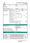
1 Confirmation sheet
The confirmation sheet, as a requisite document before placing orders, contains useful information and checklist
that help to avoid mistakes during development. Due to the updates of the confirmation sheet, please download
a newest confirmation sheet from http://www.generalplus.com/.
r
o
F
l
a
i e
t
n s
e
U
d
i
f
n 司
o
C 公
s
限
u 有
l
p 份
l
a
r
e 股
n
e 技
G 科
格
普
© Generalplus Technology Inc.
PAGE 10
y
l
n
O
V1.0 – Dec. 20, 2006
GPL162002A/162003A Programming Guide
2 Introduction
2.1
General Description
The GPL162002A/162003A, a 16-bit architecture LCD controller product, carries the Sunplus newest
16-bit microprocessor, called μ’nSP® (pronounced as micro-n-SP). This high processing speed assures
the μ’nSP® is capable of handling complex digital signal processes easily and rapidly.
Therefore, the
GPL162002A/162003A is applicable to the areas of digital sound process, voice recognition and learning
y
l
n
O
auxiliary product. The memory capacity includes a 30K-word working SRAM and 128K-word ROM.
The LCD controller is able to support maximum 320x320 dots 16 gray-level or 4096 CSTN or 640X480
l
a
i e
t
n s
e
U
d
i
f
n 司
o
C 公
s
限
u 有
l
p 份
l
a
r
e 股
n
e 技
G 科
格
普
dots 65536 color TFT displays. Other features include 64 programmable multi-functional I/Os, MP3
decode accelerator, six 16-bit timers/counters, 32768Hz Real Time Clock, Low Voltage Reset, 12-bit
ADC for touch panel and general-purpose application, 16-bit ADC/DAC for voice playling/recording,
supports SD memory card, USB 1.1version, and plus many others.
The control registers of MP3 decode accelerator will not be described in this programming guide.
Please contact Generalplus for details of MP3 decoding accelerator and decoding process.
2.2
Significant Features
z
Sunplus16-bit CPU (μ’nSP®) maximum 96MHz @ 2.7V ~ 3.6V.
z
Dual Clocks System (Phase Lock Loop and 32768 Crystal).
z
Flexible Operations: Wait//Halt/Sleep for power management.
z
Address extensible to 80M words.
z
Built-in Internal 30K-word SRAM.
z
STN LCD controller supporting up to 320x320 dots 16 gray-level or 4096 color level display.
z
TFT LCD controller supporting up to 640X480 dots 65536 color level display.
z
Two Channels 16-bit DAC audio outputs.
z
MP3 decoding accelerator.
z
7-band programmable equalizer.
z
3D Surround processor.
z
Six channels 12-bit ADC, two channels are dedicated to touch panel.
z
16-bit ADC for stereo microphone/line-in/FM record.
z
One UART & One IrDA with 8-byte transmit and receive FIFOs (queues).
z
Five chip select pins to access external ROM, SRAM, and NOR & NAND-Flash memories.
z
Six 16-bit re-loadable timers/counters and two of them support capture, comparison, and PWM
r
o
F
functions.
z
One SPI, Serial Peripheral Interface.
© Generalplus Technology Inc.
PAGE 11
V1.0 – Dec. 20, 2006
GPL162002A/162003A Programming Guide
z
Real Time Clock (RTC) supports auto-update to hour and an alarm comparison register.
z
Built-in 2.5V low voltage reset.
z
Embedded In-Circuit-Emulation.
z
More system reliability features: watchdog, illegal write reset flag, mode protection for write error,
watchdog protection for write error.
2.3
2.4
Applications
z
Advanced educational toys
z
High-end general STN/TFT LCD controller
z
Kid storybook, E-book
z
Hand-held, Multimedia LCD game
z
Educational Learning Assistant
z
Handheld organizer
z
Data bank
z
Multi Media Dictionary
z
PDA
l
a
i e
t
n s
e
U
d
i
f
n 司
o
C 公
s
限
u 有
l
p 份
l
a
r
e 股
n
e 技
G 科
格
普
y
l
n
O
The Differences between GPL162002A and GPL162003A
z
GPL162003A does not have TFT LCD feature.
Other functions and pins are compatible with
GPL162002A.
r
o
F
© Generalplus Technology Inc.
PAGE 12
V1.0 – Dec. 20, 2006
GPL162002A/162003A Programming Guide
3 System Control
3.1
Introduction
This chapter describes the body information, reset option, system clock, system reliability, and operation
mode. The features are depicted as follows:
z
Body Information.
z
Built-in 32768Hz/6MHz crystal circuit.
z
Built-in 2 Phase-Lock Loop (PLL), one pumps from 32768Hz up to 12MHz, and the other pumps
l
a
i e
t
n s
e
U
d
i
f
n 司
o
C 公
s
限
u 有
l
p 份
l
a
r
e 股
n
e 技
G 科
格
普
from 12MHz to 96MHz.
y
l
n
O
z
Support clock driver in each mode, which can generate different kinds of speed in wild range.
z
Level Low Voltage Reset (LVR).
z
Build-in Watchdog Timer.
z
Support wait mode, halt mode and sleep mode for power management.
z
The clock of each device can be turned on/off individually to reduce the operating power.
System Control Register Summary Table
Name
Address
Description
P_BodyID
0x7800
Body Identification Number Register
P_CLK_Ctrl0
0x7804
Clock On/Off Control Register 0
P_CLK_Ctrl1
0x7805
Clock On/Off Control Register 1
P_Reset_Flag
0x7806
Reset Event Flag Register
P_Clock_Ctrl
0x7807
System Clock Control Register
P_LVR_Ctrl
0x7808
Low Voltage Reset Control Register
P_Watchdog_Ctrl
0x780A
Watchdog Control Register
P_Watchdog_Clear
0x780B
Watchdog Clear Register
P_WAIT
0x780C
Wait Mode Entrance Register
0x780D
Halt Mode Entrance Register
P_SLEEP
0x780E
Sleep Mode entrance Rgister
P_Power_State
0x780F
Current Power State Register
P_PLLN
0x7817
PLL’s Divider selection
P_PLLWiatCLK
0x7818
PLL state change wait time
P_AD_Driving
0x781F
Address/Data Driving control Register
P_HALT
r
o
F
© Generalplus Technology Inc.
PAGE 13
V1.0 – Dec. 20, 2006
GPL162002A/162003A Programming Guide
3.2
Device Identification
P_BodyID
0x7800
Bit
15
14
13
Body ID Number
12
11
10
9
8
Function
7
6
5
4
3
2
1
0
0
0
0
1
0
0
0
0x8688
Default
1
0
0
Bit
Function
Type
[15:0]
BODYID
R
0
0
1
1
0
1
Description
Condition
Body Identification Register
0x8688 for
y
l
n
O
For GPL162002 and GPL162003, the ID number is GPL162002 and
fixed to 0x8688.
3.3
GPL162003
l
a
i e
t
n s
e
U
d
i
f
n 司
o
C 公
s
限
u 有
l
p 份
l
a
r
e 股
n
e 技
G 科
格
普
Reset Control
P_Reset_Flag
Bit
0x7806
Reset Event Flag Register
15
14
13
12
11
10
9
8
7
6
5
Function
-
-
-
-
-
-
-
-
-
-
-
Default
0
0
0
0
0
0
0
0
0
0
0
Bit
Function
[15:5]
4
Type
4
3
2
1
0
-
LVR
0
0
WDG WDE MPE
0
Description
0
0
Condition
Reserved
WDG
R/W
Watchdog Timeout Reset Flag
Read 0= Not Occurred
Read 1= Occurred
Write 0 = No Effect
Write 1= Clear the flag
3
WDE
R/W
Watchdog Error Write Flag
Read 0= Not Occurred
If programmers do NOT write 0xA005 to clear Read 1= Occurred
watchdog timer, this bit will be set to “1” by Write 0 = No Effect
2
MPE
R/W
GPL162002A/162003A and CPU will be reset.
Write 1= Clear the flag
Mode Protect Error Write Flag
Read 0= Not Occurred
If programmers do NOT write 0x5005 to enter Read 1= Occurred
wait mode, or NOT write 0x500A to enter halt Write 0 = No Effect
r
o
F
mode, or NOT write 0xA00A to enter standby Write 1= Clear the flag
mode,
bit
will
be
set
to”1”
by
GPL162002A/162003A, and CPU will be reset.
1
0
this
Reserved
LVR
R/W
Low Voltage Reset Flag
Read 0= Not Occurred
If GPL162002 power is below designated Read 1= Occurred
threshold voltage, this flag will be set to “1” by Write 0 = No Effect
GPL162002A/162003A, and CPU will be reset. Write 1= Clear the flag
The threshold voltage is defined in P_LVR_Ctrl.
Programmers can confirm which type of reset is activated by reading the corresponding bit.
© Generalplus Technology Inc.
PAGE 14
V1.0 – Dec. 20, 2006
GPL162002A/162003A Programming Guide
3.4
Clock Generation
There are two crystal circuits built in GPL162002A/162003A, which are for 32768Hz and 12MHz. When
the built-in USB device/host function GPL162002A/162003A is used, it is recommended that a 12MHz
crystal should be connected to GPL162002A/162003A to ensure that the error free 48MHz clock is
generated.
If the USB function is not used, users can choose to use 32768Hz crystal only.
selection between these two configurations is via the IC pin, BM2.
The
If users pull high BM2 pin at start-up,
the 12MHz and 32768Hz crystals will be used, otherwise, only the 32768 Hz crystal will be used. The
following table shows the difference between these two configurations.
BM2
l
a
i e
t
n s
e
U
d
i
f
n 司
o
C 公
s
限
u 有
l
p 份
l
a
r
e 股
n
e 技
G 科
格
普
Slow PLL
Fast PLL
(32768Hz -> 12MHz)
(12MHz -> 96MHz)
Not Active
Active
Active (After enter Fast mode)
Available when Fast PLL is on
Not Active
Active (After enter Fast mode)
USB Function
0
1
y
l
n
O
The 32768Hz crystal must be connected to GPL162002A/162003A when USB device/host function is
used, there will be two crystals connected to GPL162002A/162003A.
The 12MHz crystal is used to
generate Fast PLL from 12MHz to 96MHz, and 32768Hz crystal is used to trigger Real Time Clock unit
and 32768Hz system clock when bit C32K in P_Clock_Ctrl is set to “1”.
After power-on, the system will run at 12MHz system clock.
P_Clock_Ctrl
Bit
0x7807
15
14
Function FAST C32K
Default
Bit
15
0
0
Function Type
FAST
r
o
F
R/W
13
12
System Clock Control Register
11
- WEAK
-
0
0
0
10
9
8 7 6 5
C32KOFF KCEN 0
0
-
-
3
2 1 0
- DAPLLEN CLK96M CLKDIV
0 0 0 0
Description
4
0
0
0 0 0
Condition
Fast PLL Enable
0= Disabled (12MHz)
This control bit is used to enable internal
1= Enabled (default 48MHz)
Fast PLL logic circuit.
1. When C32K is set to 0 and this bit is
set to 1, the Fast PLL will be enabled
and generate 48 MHz clock.
2. When C32K is set to 0 and this bit is
set to 0, the Fast PLL will be disabled
and the system clock is coming from
external 12MHz Crystal (when 12MHz
crystal is used) or Slow PLL (from
32768Hz crystal to 12MHz PLL).
© Generalplus Technology Inc.
PAGE 15
V1.0 – Dec. 20, 2006
GPL162002A/162003A Programming Guide
Bit
14
Function Type
C32K
R/W
Description
Condition
CPU Clock Selection
0= High speed clock, PLLCLK.
This control bit is used to select CPU clock 1= Low Speed clock, 32768Hz.
between 32768Hz and PLL clock. When
this bit is set to “1”, the CPU clock will run
at 32768Hz, and PLL will be turned off, no
matter FAST bit is “1” or “0”.
13
12
Reserved
WEAK
R/W
32768 Hz Crystal Weak Mode Enable
0= 32768 Hz Crystal Pad Operate in
This bit is used to control the strong/ weak
Strong Mode.
mode of 32768Hz crystal pad.
1= 32768 Hz Crystal Pad Operate in
After
l
a
i e
t
n s
e
U
d
i
f
n 司
o
C 公
s
限
u 有
l
p 份
l
a
r
e 股
n
e 技
G 科
格
普
reset, the 32768Hz crystal pad will be set
Weak Mode.
to strong mode to ensure that 32768Hz
clock will start correctly.
Users can
y
l
n
O
choose to change the pad to weak mode
to save power after power-on.
11
10
9
Reserved
C32KOFF R/W
KCEN
[8:5]
4
R/W
IOB0 32768Hz Output Disable
0= IOB0 output 32768 Hz.
There will be a 32768 Hz output on IOB0;
1= IOB0 behaves as GPIO or other
write 1 to this bit will turn off this output.
special function.
IOB0 ~2 Key Change Interrupt Enable
0= IOB0~2 key change function
To turn on the key change wake-up
interrupt disable.
function of these GPIO pins, programmers
1= IOB0~2 key change function
needs to write this bit to 1.
interrupt enable.
Reserved
DAPLLEN R/W
DA/AD PLL Enable
Before
turning
0: Disable DA/AD PLL.
on
the
DA or
AD, 1: Enable DA/AD PLL.
programmers must set this bit to 1 and
wait around 1ms until the PLL output is
stable.
3
CLK96M
R/W
Current Clock Setting Register
This bit is for USB function.
r
o
F
[2:0]
CLKDIV
0: Current clock is not 96MHz.
The USB 1: Current clock is 96MHz.
function needs 48MHz clock.
When
system clock is setting to 96MHz, this bit
must be set to 1.
Clock Divide Selection.
000= SYSCLK = Clock Source
The clock divider operates under any
001= SYSCLK = Clock Source/2
kinds of configurations. It will divide the
010= SYSCLK = Clock Source/4
clock source selected by users and then
011= SYSCLK = Clock Source/8
output quotient as system clock. So the
100= SYSCLK = Clock Source/16
slowest clock in GPL162002 is 32768/128
101= SYSCLK = Clock Source/32
= 256 Hz
110= SYSCLK = Clock Source/64
111= SYSCLK = Clock Source/128
© Generalplus Technology Inc.
PAGE 16
V1.0 – Dec. 20, 2006
GPL162002A/162003A Programming Guide
The clock of each module can be turned on/off individually. This is done by writing the corresponding
bits of the P_CLK_Ctrl0 and P_CLK_Ctrl1.
If programmers write ‘1’ to the corresponding bit of
P_CLK_Ctrl0 and P_CLK_Ctrl1, the clock of the corresponding device will be turned on. If programmers
write ‘0’ to the corresponding bit of P_CLK_Ctrl0 and P_CLK_Ctrl1, the clock of the corresponding device
will be turned off.
1.
Some important facts should be noted.
To turn off the clock of system bus and system control module is not allowed.
This will cause
unexpected results and cause the system crashed.
2.
Before turning off the memory controller’s clock, be sure you are not using the external bus for a
program or placing data in the external bus.
3.
l
a
i e
t
n s
e
U
d
i
f
n 司
o
C 公
s
限
u 有
l
p 份
l
a
r
e 股
n
e 技
G 科
格
普
Be sure the corresponding device is not active before turning off its clock.
P_CLK_Ctrl0
Bit
Function
Default
0x7804
15
14
13
Function
Default
Peripheral Clock Control Register0
11
10
9
8
7
6
5
4
3
2
1
0
1
1
1
1
1
1
Clock Source [15:0]
1
1
1
P_CLK_Ctrl1
Bit
12
y
l
n
O
1
1
1
1
1
0x7805
15
14
13
12
1
1
Peripheral Clock Control Register1
11
10
9
8
7
6
5
4
3
2
1
0
1
1
1
1
1
1
Clock Source [31:16]
1
1
1
1
1
1
1
1
1
1
Please refer to the follow table for the device of each source.
Clock Source
Device
Clock Source
Device
0
System Bus
16
3D surround
1
Memory
17
USB Host
2
GPIO
18
USB Device
3
Interrupt
19
IIC
4
Time Base
20
DMA
5
Timer A/B/C/D
21
SRC
6
DAC
22
EQ
7
Uart
23
SRAM 0
8
RTC
24
IIS DAC
9
SPI
25
Key Scan
10
Analog
26
MISC
11
LCD
27
--
12
--
28
TFT
13
SP Bus
29
MP3
14
Timer E/F
30
System Control
15
SD/MMC
31
System Control
r
o
F
*
Note *: On GPL162003, this bit is invalidly.
© Generalplus Technology Inc.
PAGE 17
V1.0 – Dec. 20, 2006
GPL162002A/162003A Programming Guide
P_PLLN
0x7817
Fast PLL output divider register
Bit
15
14
13
12
11
10
9
8
7
Function
-
-
-
-
-
-
-
-
-
Default
0
0
0
0
0
0
0
0
0
Bit
Function Type
[15:7]
[6:0]
6
5
4
3
2
1
0
0
0
0
PLLN
0
0
1
0
Description
Condition
Reserved
PLLN
R/W Fast PLL’s output control
0000000~000011: reserved
This register can be changed only when 0000100: 12MHz
y
l
n
O
system is not at FAST state. This means 0000101: 15MHz
programmers need to switch PLL to slow 0000110: 18MHz
l
a
i e
t
n s
e
U
d
i
f
n 司
o
C 公
s
限
u 有
l
p 份
l
a
r
e 股
n
e 技
G 科
格
普
mode then can change PLL clock. In other 0000111: 21MHz
words, programmers must disable bit 15 of 0001000: 24 MHz
P_Clock_Ctrl (0x7807) first then change …
PLLN, enable bit 15 of P_Clock_Ctrl and
0100000: 96MHz
polling P_State(0x780F) for PLL stable.
The PLL system clock equals to PLLN
multiplied by three.
3.5
System Reliability Control
P_LVR_Ctrl
Bit
Function
Default
Bit
[15:2]
1
0x7808
Low Voltage Reset Control Register
15
14
13
12
11
10
9
8
7
6
5
4
3
2
1
0
-
-
-
-
-
-
-
-
-
-
-
-
-
-
LVROFF
-
0
0
0
0
0
0
0
0
0
0
0
0
0
0
0
0
Function
Type
Description
Condition
Reserved
LVROFF
R/W
Low Voltage Reset Off Selection
0= Enable
This register is used to turn off the LVR reset
1= Disable
when users do not wish to use the LVR function.
The LVR reset flag is still set when LVR is 1.
r
o
F
LVR reset voltage: 2.47~2.55V.
0
Reserved
P_Watchdog_Ctrl
Bit
15
Function WDGEN
Default
0
© Generalplus Technology Inc.
0x780A
14
13
12
Watchdog Reset Control Register
11
10
9
8
7
6
5
4
3
WDGS
-
-
-
-
-
-
-
-
-
-
-
0
0
0
0
0
0
0
0
0
0
0
0
PAGE 18
2
1
0
WDGPD
0
0
0
V1.0 – Dec. 20, 2006
GPL162002A/162003A Programming Guide
Bit
Function Type
15
WDGEN R/W
Description
Condition
Write once to enable Watchdog reset
0= Disabled
1= Enabled
14
WDGS
W
[13:3]
Write once to select Reset Target
0= Reset System (included
For more information about system reset
CPU)
and CPU reset, refer to Appendix.
1= Reset CPU
Reserved
[2:0]
WDGPD R/W
Watchdog period
000= 2 seconds
001= 1 second
010= 0.5 seconds
011= 0.25 seconds
l
a
i e
t
n s
e
U
d
i
f
n 司
o
C 公
s
限
u 有
l
p 份
l
a
r
e 股
n
e 技
G 科
格
普
1X0= 0.125 seconds
1X1= 62.5 seconds
P_Watchdog_Clear
Bit
15
0X780B
14
13
12
Watchdog Clear Register
11
10
9
Function
Default
Bit
[15:0]
y
l
n
O
8
7
6
5
4
3
2
1
0
0
0
0
0
0
0
0
WDGC
0
0
0
0
Function Type
WDGC
W
0
0
0
0
0
Description
Condition
Watchdog Clear Register
Write A005 to clear watchdog timer only when watchdog is
enabled (i.e. 0X780A [15] =1).
Writing other value will reset CPU.
3.6
Operation Mode Control
GPL162002A/162003A has three operation modes: Wait, Halt, and Sleep mode.
following table.
Please refer to the
Note that these three modes will all yield CPU to be powered down.
CPU
PLL (System Clock)
32768Hz Clock
After wakeup
OFF
ON
ON
Next Instruction
Halt Mode
OFF
OFF
ON (RTC)
Reset CPU
Sleep Mode
OFF
OFF
OFF
System reset
Wait Mode
r
o
F
When entering the halt mode, the system will disable PLL automatically so that it doesn’t need to change
system clock to 32768 Hz. And the system will run at the clock that set before entering halt mode when
waking up from halt mode.
If the system enters halt mode, programmers can disable RTC to save more power.
To determine CPU
is whether power-on reset or wakeup from halt mode, refer to chapter: Interrupt.
© Generalplus Technology Inc.
PAGE 19
V1.0 – Dec. 20, 2006
GPL162002A/162003A Programming Guide
P_WAIT
0x780C
Bit
15
14
13
Wait Mode Entrance Register
12
11
10
9
Function
0
0
0
0
0
0
Function Type
[15:0]
7
6
5
0
0
4
3
2
1
0
WAIT
Default
Bit
8
WAIT
W
0
0
0
Description
Condition
Wait Mode Entrance Register
Write 0x5005 to enter wait mode (stop CPUCLK source
only, but SYSCLK and 32768Hz are still valid).
l
a
i e
t
n s
e
U
d
i
f
n 司
o
C 公
s
限
u 有
l
p 份
l
a
r
e 股
n
e 技
G 科
格
普
y
l
n
O
When writing 0x5005 to control register 0x780C to enter wait mode, programmers have to add at least 6
nop instructions to make sure the GPL162002A/162003A enter wait mode successfully.
P_HALT
0x780D
Bit
15
14
13
Halt Mode Entrance Register
12
11
10
9
Function
Default
Bit
7
6
5
4
3
2
1
0
HALT
Function Type
[15:0]
8
HALT
W
Description
Condition
Halt Mode Entrance Register
Write 0x500A to enter halt mode (stop CPUCLK and
SYSCLK, but 32768Hz remains working).
The RTC is
still capable of running in this mode.
P_Sleep
Bit
0x780E
15
14
13
Sleep Mode Entrance Register
12
11
10
9
Function
8
7
6
5
4
3
2
1
0
SLEEP
Default
Bit
Function Type
[15:0]
SLEEP
r
o
F
W
Halt Mode Entrance Register
Write 0xA00A to enter standby mode (stop all clock source:
Once waking up from sleep mode, the system will be reset.
0x780F
15
14
13
Power State Register
12
Function
Default
Condition
CPUCLK, SYSCLK, and 32768Hz).
P_State
Bit
Description
11
10
9
8
7
6
5
0
© Generalplus Technology Inc.
0
0
0
4
3
2
1
0
0
0
1
State
0
0
0
PAGE 20
0
0
0
0
0
0
V1.0 – Dec. 20, 2006
GPL162002A/162003A Programming Guide
Bit
Function
Type
Description
Condition
[15:4] Reserved
R
Reserved
[2:0]
R
Current Power State Register.
000= Clock Change State.
Programmers can appreciate
001= Slow State, Use Slow PLL clock
the current power state of
or external 12MHz clock as clock
GPL162002A/162003A
source.
State
by
reading this register.
010= Fast State, Use Fast PLL as
Programmers cannot change
clock source.
system clock in changing state.
011= 32768 State, Use 32768 Hz as
clock source.
y
l
n
O
100= wait state. Use the previous
l
a
i e
t
n s
e
U
d
i
f
n 司
o
C 公
s
限
u 有
l
p 份
l
a
r
e 股
n
e 技
G 科
格
普
setting before ebter this state.
101= before stop state. Use 32768Hz
as clock sorce, this state very short
and halt or sleep state will entered.
110= halt state. Use 32768Hz as clock
source, only a little logic is active.
111= sleep state. No clock source.
Wake up by key-change.
Address/Data Bus Driving Strength Control
To meet the various requirements of external memory, in GPL162002A/162003A, it is capable of
adjusting the driving ability of address and data bus.
When external memory bus loading is small,
reducing the driving ability will reduce the bouncing time of signals. When external memory loading is
large, increasing the driving ability will reduce the signal delay.
P_AD_Driving
Bit
0x781F
15
14
13
12
Address/Data Driving Control Register
11 10
Function D_POFF D_PH D_SR D_SMT Default
r
o
F
0
0
Bit
Function Type
15
D_POFF
0
0
0
9
8
7 6
D_DRIVE
0
0
1
-
0 0
5
4
3
A_SR A_SMT 0
Description
0
0
2
1
0
A_DRIVE
0
0
1
Condition
R/W Data Bus Automatic Pull High/Low Turn Off. 0 = Automatic function is on.
This bit is used to control the automatic pull Address bus will be tied to high
high/low function of data bus when entering at the same time.
HALT mode or STANDBY mode.
This bit 1 = Automatic function is off.
also controls the state of address bus when Address bus will not be tied to
entering HALT mode or STANDBY mode.
14
D_PH
high.
R/W Data Bus Automatic Pull High/Low Selection. 0 = Pull-low data bus when
This bit is used to select the automatic pull enter HALT/STANDBY mode.
high/low function of data bus when entering 1 = Pull-high bus when enter
HALT mode or STANDBY mode. This bit is HALT/STANDBY mode.
© Generalplus Technology Inc.
PAGE 21
V1.0 – Dec. 20, 2006
GPL162002A/162003A Programming Guide
Bit
Function Type
Description
Condition
valid only when D_POFF is 0.
13
D_SR
R/W Slew Rate control of data bus.
0 = High slew rate of data bus.
This bit is used to control the slew rate of 1 = Low slew rate of data bus.
data bus.
12
D_SMT
R/W Schimit trigger of data bus.
0 = Turn-off the Schimit trigger
This bit is used to control the Schimit trigger of data bus.
1 = Turn-on the Schimit trigger
of data bus.
of data bus.
[11]
Reserved
R
Reserved.
[10:8] D_DRIVE R/W Driving Strength of data Bus.
000 = 4 mA.
l
a
i e
t
n s
e
U
d
i
f
n 司
o
C 公
s
限
u 有
l
p 份
l
a
r
e 股
n
e 技
G 科
格
普
This register is used to control the driving 001 = 4 mA.
capability of data bus.
010 = 8 mA.
011 = 8 mA.
y
l
n
O
100 = 12 mA.
101 = 12 mA.
110 = 16 mA.
111 = 16 mA.
[7:6]
Reserved
5
A_SR
R
Reserved
R/W Slew Rate control of address bus.
0 = High slew rate of address
This bit is used to control the slew rate of bus.
1 = Low slew rate of address
address bus.
bus.
4
A_SMT
R/W Schimit trigger of address bus.
0 = Turn-off the Schimit trigger
This bit is used to control the Schimit trigger of address bus.
1 = Turn-on the Schimit trigger
of address bus.
of address bus.
[3]
Reserved
[2:0]
A_DRIVE
R
Reserved.
R/W Driving Strength of Address Bus.
000 = 4 mA.
This register is used to control the driving 001 = 4 mA.
capability of address bus.
010 = 8 mA.
011 = 8 mA.
r
o
F
© Generalplus Technology Inc.
100 = 12 mA.
101 = 12 mA.
110 = 16 mA.
111 = 16 mA.
PAGE 22
V1.0 – Dec. 20, 2006
GPL162002A/162003A Programming Guide
3.7
Special Note
GPL162002A/162003A supports three boot modes, for details, please refer to Memory Chapter. To
select which boot mode is used, GPL162002A/162003A will detect pins, BM0 and BM1, at power-on or
hardware reset cycle. When BM [1:0] =00, the system will boot from external MCS0 memory. When
BM [1:0] =10, the system will boot from internal ROM. When BM [1:0] = 11 or 01, the system will boot
form external EMUCE Memory instead of internal ROM.
r
o
F
l
a
i e
t
n s
e
U
d
i
f
n 司
o
C 公
s
限
u 有
l
p 份
l
a
r
e 股
n
e 技
G 科
格
普
© Generalplus Technology Inc.
PAGE 23
y
l
n
O
V1.0 – Dec. 20, 2006
GPL162002A/162003A Programming Guide
4 Memory
4.1
Introduction
GPL162002A/162003A has a built-in internal ROM, SRAM and a NOR type flash memory controller with
AMBA like interface. There are five chip select pins and one chip select pin for emulation, each memory
device has 256 pages, and each page is 64K words.
So, the controller can totally support up to 80M
words for NOR type flash memories.
y
l
n
O
In addition to the ROM/SRAM/NOR type flash memory controller, the NAND type flash memory controller
for 8 bits or 16 bits NAND type flash memories and SM (Smart Media) flash memories are available, and
l
a
i e
t
n s
e
U
d
i
f
n 司
o
C 公
s
限
u 有
l
p 份
l
a
r
e 股
n
e 技
G 科
格
普
it supports H/W ECC (Error Correction Code).
4.2
FEATURE
z
Support ROM / SRAM / NOR type flash memory.
z
Five banks (5 chips select) are available for the supported memories.
z
Each bank size is up to 256 pages, and each page is 64K words, the controller can totally support up
to 80M words for NOR type flash memories.
4.3
z
Supply the interface to access 8-bit or 16-bit NAND Flash memory.
z
Support flexible Command/Address mode.
z
Support Auto page Program/Read.
z
Support single Program/Read by Firmware.
z
Provide DMA interrupt request.
z
Support NAND hardware ECC.
z
Each memory can be configured as 8-bit mode access.
Memory Mappings
GPL162002A/162003A has a built-in 30K-word SRAM and a 128K-word internal ROM.
r
o
F
Associated with
external memory devices, GPL162002A/162003A is able to address up to 81920K-word locations.
GPL162002A/162003A supports three boot modes, Boot from internal ROM, Boot from external ROM
and boot EMU mode. The memory mappings of these three modes are as follows.
1.
Internal ROM mode
When BM [1:0] = 10, GPL162002A/162003A will boot from internal embedded ROM. This mode is
active at end product stage.
© Generalplus Technology Inc.
The memory mapping of the internal ROM mode is shown below.
PAGE 24
V1.0 – Dec. 20, 2006
GPL162002A/162003A Programming Guide
BOOT FROM INTERNAL ROM
0x0000_0000
RAM 30KW
0x0000_77FF
Peripheral / System Control
0x0000_8000
Embadded ROM 128KW
0x0002_7FFF
Reserved
Memory 0
0x0003_0000
l
a
i e
t
n s
e
U
d
i
f
n 司
o
C 公
s
限
u 有
l
p 份
l
a
r
e 股
n
e 技
G 科
格
普
CS 0
y
l
n
O
Memory 1
CS 1
Memory 2
CS 2
CS3
Memory 3
CS 4
Memory 4
r
o
F
© Generalplus Technology Inc.
PAGE 25
V1.0 – Dec. 20, 2006
GPL162002A/162003A Programming Guide
2.
EMU mode
When BM [1:0] = 01 or 11, GPL162002A/162003A boot from external memory instead internal ROM.
In this mode, IC pin, BKCSB5 (EMUCE), will change to low when CPU access address from 0x8000
to 0x27FFF. The memory mapping of EMU mode is shown below.
BOOT EMU ROM
0x0000_0000
RAM 30KW
0x0000_77FF
Peripheral / System Control
y
l
n
O
EMU memory
l
a
i e
t
n s
e
U
d
i
f
n 司
o
C 公
s
限
u 有
l
p 份
l
a
r
e 股
n
e 技
G 科
格
普
0x0000_8000
EMUCE
128K ROM space
0x0002_7FFF
Memory 0
Reserved
0x0003_0000
CS 0
Memory 1
CS 1
Memory 2
CS 2
CS3
Memory 3
CS 4
Memory 4
r
o
F
© Generalplus Technology Inc.
PAGE 26
V1.0 – Dec. 20, 2006
GPL162002A/162003A Programming Guide
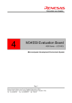
3.
MCS0 boot mode
When BM [1:0] =00, GPL162002 will boot from external MCS0 memory.
In this mode, default
internal rom area 0xF800~0xFFFF are mapped to 0x3F800~0x3FFFF. We call these areas as CPU
boot code area.
And the area size can be adjusted dynamically by setting control register
P_MAPSEL (0x7816). The memory mapping of MCS0 boot mode is shown below.
BOOT MCS0 ROM
0x0000_0000
RAM 30KW
l
a
i e
t
n s
e
U
d
i
f
n 司
o
C 公
s
限
u 有
l
p 份
l
a
r
e 股
n
e 技
G 科
格
普
0x0000_77FF
0x0000_8000
Peripheral / System Control
Embadded ROM 30KW
y
l
n
O
The same mapping
0x0000_F800
0x0001_0000
Embadded ROM 96KW
Memory 0
0x0000_F800
0x0002_7FFF
Reserved
0x0003_0000
CS 0
0x0003_F800
0x0003_FFFF
Memory 1
CS 1
Memory 2
CS 2
Memory 3
CS3
Memory 4
CS 4
r
o
F
For GPL162002A/162003A, each page size is 64K-word.
pages (16384KW) of each memory controller.
GPL162002A/162003A can access up to 256
There are total five memory controllers on
GPL162002A/162003A so that it can totally access up to 81920KW; in CPU view, however, it can only
address up to 4MW. To access whole 81920KW, programmers need to use one control register to
switch bank. Besides, GPL162002A/162003A supports five chip select signals to enable five external
memory devices. Some of these chip select pins are shared with other special functions. For detail,
please refer to I/O Port.
The 30K-word Internal SRAM (including stack) area is located in 0x000000 ~ 0x0077FF, and system
© Generalplus Technology Inc.
PAGE 27
V1.0 – Dec. 20, 2006
GPL162002A/162003A Programming Guide
control registers and peripheral control registers reside in the 2K-word area, from 0x007800 to 0x007FFF.
Internal SRAM, system control register and peripheral control registers are positioned in the lower
32K-word of Page0. The layout of internal ROM starts from the upper 32K-word in page0, and ends up
the upper 32K-word of Page2 (from 0x008000 to 0x027FFF).
stored in Page0, Page1, and Page2.
Therefore, internal resources will be
Note that the higher 32K-word of Page2 is reserved
(0x028000~0x02FFFF).
y
l
n
O
The address of the five external memory devices starts at 0x0003_0000, total 81920K-word. In other
words, the size of five devices is programmable by software, but the addressing space of these five
l
a
i e
t
n s
e
U
d
i
f
n 司
o
C 公
s
限
u 有
l
p 份
l
a
r
e 股
n
e 技
G 科
格
普
devices cannot be overlapped.
Besides, if the system has to connect a NAND Flash, it will use one of
these five chip select pins. It is recommanded to use the system’s last chip select pin.
See the following formula:
Size of (External Device0 + External Device1 + External Device2 + External Device3 + External Device4)
≤81920K words
The method to define the address mapping of five external memory devices is to set up the size of each
memory device. In GPL162002A/162003A, the start address of CS0 is 0x0003_0000. After the size of
CS0 is given, the CS1 address is defined impliedly.
based on each 64K-word or saying 0x010000).
That is 0x0003_0000 + size of CS0 (the unit is
After the CS1 is settled, the start address of CS2 is
automatically defined, similar for CS3, CS4.
Example:
Suppose we have two 256K-Word SRAMs for CS0 and CS1 and A 512K-Word Flash memory and a
512K-Word ROM for CS2 and CS3, respectively.
Arrangement the following:
CS0: 0x0003_0000 ~ 0x006_FFFF as 256KW SRAM
r
o
F
CS1: 0x0007_0000 ~ 0x000A_FFFF as 256KW SRAM
CS2: 0x000B_0000 ~ 0x0013_FFFF as 512KW Flash
CS3: 0x0014_0000 ~ 0x001B_FFFF as 512KW ROM
In most cases, not all five external device will be used, nor all 24 address lines.
Therefore,
GPL162002A/162003A allows system designers to convert unused CS0 ~ CS4, Address signal (A17 ~
A23) or even read/write signal (#WE, #RE) to general purpose I/O. Theses signals are memory control
signals in default after CPU resets.
After configuring the control registers, these signals can be one of
GPIOs. For details, please refer to Chapter: I/O Ports.
© Generalplus Technology Inc.
PAGE 28
V1.0 – Dec. 20, 2006
GPL162002A/162003A Programming Guide
4.4
4.5
Memory Access Pin Configuration
Name
I/O
Description
MD[15:0]
I/O
Memory 16-bit data bus (Dedicated)
MA[16:0]
O
Memory address bus [16:0] (Dedicated)
MA[23:17]
O
Memory address bus [23:17] (shared with GPIO PortD[11:5] )
CS[4:0]
O
Memory chip selection signal (shared with GPIO PortD[4:0] )
WE
O
Memory write enable control signal (shared with GPIO PortB3)
RE
O
Memory read enable control signal (shared with GPIO PortB4)
l
a
i e
t
n s
e
U
d
i
f
n 司
o
C 公
s
限
u 有
l
p 份
l
a
r
e 股
n
e 技
G 科
格
普
Control Registers
y
l
n
O
Memory Control Register Summary Table
Name
Address
Description
P_MCS0_Ctrl
0x7820
Chip Selection 0 Memory Device Control Register
P_MCS1_Ctrl
0x7821
Chip Selection 1 Memory Device Control Register
P_MCS2_Ctrl
0x7822
Chip Selection 2 Memory Device Control Register
P_MCS3_Ctrl
0x7823
Chip Selection 3 Memory Device Control Register
P_MCS4_Ctrl
0x7824
Chip Selection 4 Memory Device Control Register
P_EMUCS_Ctrl
0x7825
EMU Chip Selection Memory Device Control Register
P_MCS_Byte_Sel
0x7826
CS0~CS4 and EMUCS Word/Byte Data Select
P_MCS3_WETimingCtrl
0x7827
MCS3 WE timing control register
P_MCS4_WETimingCtrl
0x7828
MCS4 WE timing control register
P_MCS3_RDTimingCtrl
0x7829
MCS3 RD timing control register
P_MCS4_RDTimingCtrl
0x782A
MCS4 RD timing control register
P_MCS3_TimingCtrl
0x782B
MCS3 CS timing control register
P_MCS4_TimingCtrl
0x782C
MCS4 CS timing control register
P_Mem_Ctrl
0x7840
Memory Control Register
P_Addr_Ctrl
0x7841
Memory A17~A25 Control Register
P_BankSwitch_Ctrl
0x7810
Bank Switch Control Register
P_MAPSEL
0x7816
CS0 boot mapping size select register
r
o
F
The P_MCS0_Ctrl, P_MCS1_Ctrl, P_MCS2_Ctrl, P_MCS3_Ctrl and P_MCS4_Ctrl are control registers
for memory devices on chip select 0, 1, 2, 3, and 4.
To make system operation more reliable,
programmers should set appropriate wait cycles for each external device on these five control registers.
The longer the wait period is, the more reliable a system is. The shorter the wait period is, the higher
the performance is, but the less reliable a system is.
© Generalplus Technology Inc.
PAGE 29
V1.0 – Dec. 20, 2006
GPL162002A/162003A Programming Guide
Wait state setup has one limitation.
That is, device access time should always be smaller than
designated wait cycle which is determined by number of system clocks.
There is indeed access time
information on memory device data sheet, but this access time criterion is under certain operating voltage
and bus loading. Therefore, programmers should weigh some margins while trying to determine the
period of wait cycle, especially when system voltage varies (not fixed to some specified operating
voltages) and when there are too many memory devices in a system. (Bus loading)
P_MCS0_Ctrl
Bit
15
Function
Default
Bit
0x7820
14
13
12
CS0 Device Control Register
11
10
9
8
CS0SIZE
7
6
5
CS0MD
4
3
2
WARWAT
0
0
0
0
0
Function Type
0
0
0
0
1
1
Description
[15:8] CS0SIZE R/W
0
CS0WAIT
l
a
i e
t
n s
e
U
d
i
f
n 司
o
C 公
s
限
u 有
l
p 份
l
a
r
e 股
n
e 技
G 科
格
普
0
y
l
n
O
1
1
1
1
1
Condition
Memory Device Size on Chip Select 0 (CS0),
Range= 0 ~255
unit is 64K words. “CS0SIZE [7:0] + 1” defines Size=(CS0SIZE[7:0] +1)*
the number of page for the entire memory 64Kword
device on CS0.
Size Range= 64K-word ~
Page size is 64K-word.
16384K-word
[7:6]
CS0MD
R/W
CS0 Memory Device Access Mode
00= ROM/SRAM
To define which memory device on CS0, such 01= ROM/SRAM
as ROM, SRAM, NOR or NAND Flash 10= NOR Flash
memories.
If NAND Flash is selected, the 11= NAND Flash
MCS0 pin will keep low until it is changed to
other memory type.
[5:4]
WARWAT R/W
SRAM Write after Read Wait State
WARWAT[1:0]*SYSCLK
When data is written to memory, and then read
it immediately from the same address, CPU will
wait WARWAT [1:0*] SYSCLK to read it.
[3:0]
CS0WAIT R/W
r
o
F
CS0 Memory Device Access Wait State
Range= 0 ~15
Setup Criterion:
Tw= (CS0WAIT[3:0] + 1) *
((CS0WAIT[3:0] + 1) * SYSCLK cycle)
SYSCLK
> memory device access time
P_MCS1_Ctrl
Bit
0x7821
15
14
13
0
0
0
Function
Default
Bit
12
CS1 Device Control Register
11
10
9
8
0
0
0
CS1SIZE
Function Type
[15:8] CS1SIZE R/W
© Generalplus Technology Inc.
0
0
7
6
CS1MD
0
0
5
4
3
WARWAT
1
Description
1
2
1
0
CS1WAIT
1
1
1
1
Condition
Memory Device Size on Chip Select 1 (CS1),
Range= 0 ~255
unit is 64K words. “CS1SIZE [7:0] + 1” defines
Size=(CS1SIZE[7:0] +1)*
PAGE 30
V1.0 – Dec. 20, 2006
GPL162002A/162003A Programming Guide
Bit
Function Type
Description
Condition
the number of page for the entire memory
64Kword
device on CS1.
Size Range= 64K-word ~
Page size is 64K-word.
16384K-word
[7:6]
CS1MD
R/W
CS1 Memory Device Access Mode
00= ROM/SRAM
To define which memory device on CS0, such
01= ROM/SRAM
as ROM, SRAM, NOR or NAND Flash
10= NOR Flash
memories.
11= NAND Flash
If NAND Flash is selected, the
MCS1 pin will keep low until it is changed to
other memory type.
[5:4]
WARWAT R/W
SRAM Write after Read Wait State
l
a
i e
t
n s
e
U
d
i
f
n 司
o
C 公
s
限
u 有
l
p 份
l
a
r
e 股
n
e 技
G 科
格
普
When data is written to memory, and then read
it immediately from the same address, CPU will
wait WARWAT [1:0*] SYSCLK to read it.
[3:0]
CS1WAIT R/W
y
l
n
O
WARWAT[1:0]*SYSCLK
CS1 Memory Device Access Wait State
Range= 0 ~15
Setup Criterion:
Tw= (CS1WAIT[3:0] + 1) *
((CS1WAIT[3:0] + 1) * SYSCLK cycle)
SYSCLK
> memory device access time
P_MCS2_Ctrl
Bit
15
Function
Default
Bit
0x7822
14
13
12
CS2 Device Control Register
11
10
9
8
7
CS2SIZE
0
0
0
0
6
CS2MD
0
0
Function Type
0
0
0
0
5
4
3
WARWAT
1
Description
1
2
1
0
CS2WAIT
1
1
1
1
Condition
[15:8] CS2SIZE R/W Memory Device Size on Chip Select 2 (CS2), Range= 0 ~255
unit is 64K words. “CS2SIZE [7:0] + 1” defines Size=(CS2SIZE[7:0] +1)*
the number of page for the entire memory 64Kword
device on CS2.
Size Range= 64K-word ~
Page size is 64K-word.
16384K-word
[7:6]
CS2MD
R/W CS2 Memory Device Access Mode
00= ROM/SRAM
To define which memory device on CS2, such 01= ROM/SRAM
r
o
F
[5:4]
as
ROM,
memories.
SRAM,
NOR
or
NAND
Flash 10= NOR Flash
If NAND Flash is selected, the 11= NAND Flash
MCS2 pin will keep low until it is changed to
other memory type.
WARWAT R/W SRAM Write after Read Wait State
WARWAT[1:0]*SYSCLK
When data is written to memory, and then read
it immediately from the same address, CPU will
wait WARWAT [1:0*] SYSCLK to read it.
[3:0]
CS2WAIT R/W CS2 Memory Device Access Wait State
© Generalplus Technology Inc.
Range= 0 ~15
Setup Criterion:
Tw= (CS2WAIT[3:0] + 1) *
((CS2WAIT[3:0] + 1) * SYSCLK cycle)
SYSCLK
PAGE 31
V1.0 – Dec. 20, 2006
GPL162002A/162003A Programming Guide
Bit
Function Type
Description
Condition
> memory device access time
P_MCS3_Ctrl
Bit
0x7823
15
14
13
Function
11
10
9
8
7
CS3SIZE
Default
Bit
12
CS3 Device Control Register
0
0
0
0
6
CS3MD
0
0
Function Type
0
0
0
0
5
4
3
WARWAT
1
1
1
0
CS3WAIT
1
Description
[15:8] CS3SIZE R/W
2
1
1
1
y
l
n
O
Condition
Memory Device Size on Chip Select 3 (CS3),
Range= 0 ~ 255
unit is 64K words. “CS3SIZE [7:0] + 1” defines
Size=(CS3SIZE[7:0] +1)*
the number of page for the entire memory
64Kword
device on CS3.
Size Range= 64K-word ~
l
a
i e
t
n s
e
U
d
i
f
n 司
o
C 公
s
限
u 有
l
p 份
l
a
r
e 股
n
e 技
G 科
格
普
Page size is 64K-word.
16384K-word
[7:6]
CS3MD
R/W
CS3 Memory Device Access Mode
00= ROM/SRAM
To define which memory device on CS3, such
01= ROM/SRAM
as
10= NOR Flash
ROM,
memories.
SRAM,
NOR
or
NAND
Flash
If NAND Flash is selected, the
11= NAND Flash
MCS3 pin will keep low until it is changed to
other memory type.
[5:4]
WARWAT R/W
SRAM Write after Read Wait State
WARWAT[1:0]*SYSCLK
When data is written to memory, and then read
it immediately from the same address, CPU will
wait WARWAT [1:0*] SYSCLK to read it.
[3:0]
CS3WAIT R/W
CS3 Memory Device Access Wait State
Range= 0 ~15
Setup Criterion:
Tw= (CS3WAIT[3:0] + 1) *
((CS3WAIT[3:0] + 1) * SYSCLK cycle)
SYSCLK
> memory device access time
P_MCS4_Ctrl
Bit
15
Function
r
o
F
Default
Bit
0x7824
14
13
12
CS4 Device Control Register
11
10
9
8
CS4SIZE
0
0
0
0
0
Function Type
7
6
CS4MD
0
0
0
0
0
5
4
3
2
WARWAT
1
1
Description
1
0
CS4WAIT
1
1
1
1
Condition
[15:8] CS4SIZE R/W Memory Device Size on Chip Select 4(CS4), Range= 0 ~255
unit is 64K words. “CS4SIZE [7:0] + 1” defines Size=(CS4SIZE[7:0]+1)*64K
the number of page for the entire memory word
device on CS4.
Page size is 64K-word.
SizeRange=64K-word~
16384K-word
[7:6]
CS4MD
© Generalplus Technology Inc.
R/W
CS4 Memory Device Access Mode
00= ROM/SRAM
To define which memory device on CS4,
01= ROM/SRAM
PAGE 32
V1.0 – Dec. 20, 2006
GPL162002A/162003A Programming Guide
Bit
Function Type
Description
Condition
such as ROM, SRAM, NOR or NAND Flash
10= NOR Flash
memories. If NAND Flash is selected, the
11= NAND Flash
MCS4 pin will keep low until it is changed to
other memory type.
[5:4]
WARWAT R/W
SRAM Write after Read Wait State
WARWAT[1:0]*SYSCLK
When data is written to memory, and then
read it immediately from the same address,
CPU will wait WARWAT [1:0*] SYSCLK to
read it.
[3:0]
CS4WAIT R/W
Range= 0 ~15
Setup Criterion:
Tw= (CS4WAIT[3:0] + 1) *
((CS4WAIT[3:0] + 1) * SYSCLK cycle)
SYSCLK
l
a
i e
t
n s
e
U
d
i
f
n 司
o
C 公
s
限
u 有
l
p 份
l
a
r
e 股
n
e 技
G 科
格
普
> memory device access time
P_EMUCS_Ctrl
Bit
0x7825
15
14
13
12
0
0
0
0
Function
Default
Bit
[7:6]
[5:4]
EMU Device Control Register
11
10
9
8
0
0
0
0
-
Function Type
[15:8]
y
l
n
O
CS4 Memory Device Access Wait State
7
6
EMCMD
0
1
5
4
3
WARWAT
0
0
Description
2
1
0
EMUCSWAIT
1
1
1
1
Condition
Reserved.
EMCMD
R/W
WARWAT R/W
EMU Memory Device Access Mode
00= ROM/SRAM
To define which memory device is on
01= ROM/SRAM
EMUCE, such as ROM, SRAM, NOR or
10= NOR Flash
NAND Flash memories.
11= NAND Flash
SRAM Write after Read Wait State
WARWAT[1:0]*SYSCLK
When data is written to memory, and then
read
it
immediately
from
the
same
address, CPU will wait WARWAT [1:0*]
SYSCLK to read it.
[3:0] EMUCS
r
o
F
WAIT
R/W
EMU Memory Device Access Wait State
Range= 0 ~15
Setup Criterion:
Tw= (EMUCEWAIT[3:0] + 1) *
((EMUCSWAIT[3:0] + 1) * SYSCLK cycle)
SYSCLK
> memory device access time
GPL162002A/162003A allows programmers to define wait cycles for each external device by setting
corresponding CS0WAIT, CS1WAIT, CS2WAIT, CS3WAIT, CS4WAIT and EMUCSWAIT control bits.
The default wait cycles are 16 system clock cycles to ensure system working reliably without any setup.
GPL162002A/162003A can support access 8-bit memory mode via setup P_MCS_Byte_Sel register.
The 8-bit mode for each chip select is based on bit [4:0] of P_MCS_Byte_Sel. In this mode, only low
© Generalplus Technology Inc.
PAGE 33
V1.0 – Dec. 20, 2006
GPL162002A/162003A Programming Guide
byte data is effective and high byte data will be filled all zeros.
P_MCS_Byte_Sel
Bit
15
0x7826
14
13
12
MCS Word/Byte Data Select register
11
10
Function
Default
Bit
9
8
7
0
0
0
0
0
0
0
0
Function Type
0
5
4
3
2
1
0
EMU
S4
S3
S2
S1
S0
0
0
0
0
0
0
0
Description
[15:6]
Condition
Reserved
[5]
EMU
[4]
[3]
l
a
i e
t
n s
e
U
d
i
f
n 司
o
C 公
s
限
u 有
l
p 份
l
a
r
e 股
n
e 技
G 科
格
普
R/W If This bit is set 1, then CS4 accesses data in 8-bit mode.
0: 16-bit
Only low byte available. High byte will be filled zero.
1: 8-bit
R/W If This bit is set 1, then CS3 accesses data in 8-bit mode.
0: 16-bit
Only low byte available. High byte will be filled zero.
1: 8-bit
R/W If This bit is set 1, then CS2 accesses data in 8-bit mode.
0: 16-bit
Only low byte available. High byte will be filled zero.
1: 8-bit
S1
R/W If This bit is set 1, then CS1 accesses data in 8-bit mode.
0: 16-bit
Only low byte available. High byte will be filled zero.
1: 8-bit
S0
R/W If This bit is set 1, then CS0 accesses data in 8-bit mode.
0: 16-bit
Only low byte available. High byte will be filled zero.
1: 8-bit
S2
[1]
[0]
P_MCS3_WETimingCtrl 0x7827
Bit
15
Function
Init
14
13
12
MCS3 WE timing control register
11
10
9
8
7
6
5
4
3
2
1
0
WEB3NUM
0
0
0
0
0
Function Type
[15:4]
y
l
n
O
0: 16-bit
1: 8-bit
S3
[2]
R/W If This bit is set 1, then EMUCS accesses data in 8-bit mode.
Only low byte available. High byte will be filled zero.
S4
Bit
6
-
0
0
0
0
0
0
0
Description
0
0
0
0
Condition
Reserved
[3:0] WEB3NUM R/W CSB3 and WEB3 Program Timing Register.
Range= 0 ~15
Tw= WEB3NUM[3:0] * SYSCLK
r
o
F
P_MCS4_WETimingCtrl 0x7828
Bit
15
14
13
12
MCS4 WE timing control register
11
10
9
8
7
6
5
4
3
Function
Init
Bit
1
0
WEB4NUM
0
Function
[15:4]
[3:0]
2
0
0
0
0
Type
0
0
0
0
Description
0
0
0
0
0
0
0
Condition
Reserved
WEB4NUM
R/W CSB4 and WEB4 Program Timing
Tw= WEB4NUM[3:0] * SYSCLK
Register.
© Generalplus Technology Inc.
Range= 0 ~15
PAGE 34
V1.0 – Dec. 20, 2006
GPL162002A/162003A Programming Guide
P_MCS3_RDTimingCtrl
Bit
15
14
0x7829
13
12
MCS3 RD timing control register
11
10
9
8
7
6
5
4
3
Function
Init
0
Function
0
0
0
Type
0
0
0
0
0
0
0
0
Description
[15:4]
[3:0]
0
0
0
Reserved
RDB3NUM
R/W CSB3 and RDB3 Program Timing
Bit
Range= 0 ~15
15
14
0x782A
13
12
MCS4 RD timing control register
11
10
9
8
7
6
5
4
3
Function
Init
2
1
0
RDB4NUM
0
Function
[15:4]
y
l
n
O
Tw= RDB3NUM[3:0] * SYSCLK
l
a
i e
t
n s
e
U
d
i
f
n 司
o
C 公
s
限
u 有
l
p 份
l
a
r
e 股
n
e 技
G 科
格
普
P_MCS4_RDTimingCtrl
0
0
0
0
Type
0
0
0
0
0
0
0
Description
0
0
0
0
Condition
Reserved
[3:0] RDB4NUM
R/W
P_MCS3_TimingCtrl
Bit
15
CSB4 and RDB4 Program Timing
Range= 0 ~15
Register.
Tw= RDB4NUM[3:0] * SYSCLK
0x782B
14
13
12
MCS3 CS timing control register
11
10
9
8
7
6
5
4
3
Function
Init
0
Function
[15:4]
2
1
0
CSB3NUM
0
Bit
[3:0]
0
Condition
Register.
Bit
1
RDB3NUM
0
Bit
2
0
0
0
Type
0
1
1
0
0
0
0
Description
0
0
0
0
Condition
Reserved
CSB3NUM
R/W CSB3 Program Timing Register.
Range= 0 ~15
Tw= CSB3NUM[3:0] * SYSCLK
r
o
F
P_MCS4_TimingCtrl
Bit
0x782C
MCS4 CS timing control register
15
14
13
12
11
10
9
8
7
6
5
4
3
0
0
0
0
0
0
1
1
0
0
0
0
0
Function
Init
Bit
1
0
CSB4NUM
Function
[15:4]
[3:0]
2
Type
Description
0
0
0
Condition
Reserved
CSB4NUM
R/W CSB4 Program Timing Register.
Range= 0 ~15
Tw= CSB4NUM[3:0] * SYSCLK
© Generalplus Technology Inc.
PAGE 35
V1.0 – Dec. 20, 2006
GPL162002A/162003A Programming Guide
Among all the chip select signals, CS3 and CS4 access setup time and hold time can be adjusted. This
makes CS3 and CS4 more flexible for special memory devices, such as Compact Flash cards. Please
refer to the following timing diagrams.
CS3, CS4 Timing
Addr
address valid
CS3(4)WAIT
l
a
i e
t
WE
n
s
e
(RD)
U
d
i
f
n 司
o
CS0~CS2 Timing
C 公
s
限
Addr
address
valid
u 有
l
p 份
l
CSX
a
r
e 股
WE
n
(RD)
e 技
G 科
格
普
r
o
F
CS3
y
l
n
O
WEB#NUM
WEB#NUM
CSB#NUM
CSB#NUM
CS#WAIT
Following control registers are used to change the memory address signals and memory control signals
to GPIO functions.
After power-on reset, the default settings of these pins are as memory access
signals, except CS4. If there is no external memory device, or external devices are less than five, some
of memory addresses or memory control signals can be used as GPIOs. To change these pins to
GPIOs, programmers must write certain word to a corresponding control register.
© Generalplus Technology Inc.
PAGE 36
V1.0 – Dec. 20, 2006
GPL162002A/162003A Programming Guide
P_Mem_Ctrl
0x7840
Memory Control Register
Bit
15
14
13
12
11
10
9
8
7
6
5
Function
-
-
-
-
-
-
-
-
WE
RD
-
Default
0
0
0
0
0
0
0
0
1
1
0
Bit
Function Type
Reserved
[13:8]
These bits have to be set as “0.”
WE
R/W
3
2
0
1
1
Memory Write Enable Signal WEB.
1
l
a
i e
t
n s
e
U
d
i
f
n 司
o
C 公
s
限
u 有
l
p 份
l
a
r
e 股
n
e 技
G 科
格
普
R/W
1
y
l
n
O
0= Disable
When write 0 to this bit, PortB [3] becomes GPIO.
RD
0
Condition
1= Enable
Otherwise, PortB [3] remains Write Enable Signal.
6
1
MCS4 MCS3 MCS2 MCS1 MCS0
Description
[15:14]
7
4
Memory Read Enable Signal OEB.
0= Disable
When write 0 to this bit, PortB [4] becomes GPIO.
1= Enable
Otherwise, PortB [4] remains Read Enable Signal.
5
Reserved
4
MCS4
3
R/W
MCS3
2
R/W
MCS2
1
R/W
MCS1
0
R/W
MCS0
R/W
P_Addr_Ctrl
Bit
Function
Default
r
o
F
Bit
Memory chip select 4 enable pin.
0= Disable
MCS4 is shared with IOD[4].
1= Enable
Memory chip select 3 enable pin.
0= Disable
MCS3 is shared with IOD[3].
1= Enable
Memory chip select 2 enable pin.
0= Disable
MCS2 is shared with IOD[2].
1= Enable
Memory chip select 1 enable pin.
0= Disable
MCS1 is shared with IOD[1].
1= Enable
Memory chip select 0 enable pin.
0= Disable
MCS0 is shared with IOD[0].
1= Enable
0x7841
15
14
13
12
11
10
9
8
7
-
-
-
-
-
-
-
-
-
0
0
0
0
0
0
0
0
0
Function
Type
[15:7]
6
5
4
3
Memory Address A17~A25 Control Register
6
5
4
3
2
1
0
MA23 MA22 MA21 MA20 MA19 MA18 MA17
1
1
Description
1
1
1
1
1
Condition
Reserved
MA23
MA22
MA21
MA20
© Generalplus Technology Inc.
R/W
R/W
R/W
R/W
Address bus MA23 enable pin.
0= Disable
MA23 is shared with IOD[11].
1= Enable
Address bus MA22 enable pin.
0= Disable
MA22 is shared with IOD[10].
1= Enable
Address bus MA21 enable pin.
0= Disable
MA21 is shared with IOD[9].
1= Enable
Address bus MA20 enable pin.
0= Disable
MA20 is shared with IOD[8].
1= Enable
PAGE 37
V1.0 – Dec. 20, 2006
GPL162002A/162003A Programming Guide
Bit
Function
Type
2
MA19
R/W
1
MA18
0
4.6
MA17
R/W
R/W
Description
Condition
Address bus MA19 enable pin
0= Disable
MA19 is shared with IOD[7]
1= Enable
Address bus MA18 enable pin
0= Disable
MA18 is shared with IOD[6]
1= Enable
Address bus MA17 enable pin
0= Disable
MA17 is shared with IOD[5]
1= Enable
Bank Switch Control
y
l
n
O
As mentioned in the previous sections, GPL162002A/162003A is able to access totally 81920KW.
l
a
i e
t
n s
e
U
d
i
f
n 司
o
C 公
s
限
u 有
l
p 份
l
a
r
e 股
n
e 技
G 科
格
普
However, in CPU view, it can only address up to 4MW, 0x000000 ~ 0x3FFFFF. To use the address
space larger than 0x3FFFFF, programmers need to set bank switch control register before accessing the
space.
The address from 0x0020_0000 to 0x003F_FFFF is the memory space used to switch bank, and
each bank size is 2MW.
r
o
F
© Generalplus Technology Inc.
PAGE 38
V1.0 – Dec. 20, 2006
GPL162002A/162003A Programming Guide
P_BankSwitch_Ctrl
Bit
15
0x7810
14
13
12
Bank Switch Control Register
11
Function
Default
10
9
8
7
6
5
4
0
0
0
0
0
3
2
1
0
0
1
Bank
0
0
0
0
Bit
Function
Type
[15:6]
Reserved
R
Reserved
[5:0]
Bank
W
Bank Number Register
0
0
0
0
0
Description
Condition
When these bits are set to 0x01, Physical
address 0x200000~0x3FFFF will be mapped to
0x20000~0x3FFFFF.
l
a
i e
t
n s
e
U
d
i
f
n 司
o
C 公
s
限
u 有
l
p 份
l
a
r
e 股
n
e 技
G 科
格
普
When these bits are set to 0x02, Physical
address 0x400000~0x5FFFF will be mapped to
0x20000~0x3FFFFF.
y
l
n
O
And so on.
When BM [1:0] is set to 2b’00, the external MCS0 boot mode is selected. The mapping size of external
boot area can be changed by setting P_MAPSEL register.
P_MAPSEL
Bit
0x7816
15
14
13
12
CS0 boot mapping size select register
11
10
Function
Default
Bit
9
8
7
6
5
4
3
2
-
0
0
0
0
0
Function Type
0
0
0
[15:3]
Reserved
R
Reserved
[2:0]
MAPSEL
W
CS0 boot map size register.
When programmers use MCS0
mode,
0
MAPSEL
Description
boot
1
0
0
0
0
0
0
0
0
Condition
000: 2K (0xF800~0xFFFF) is mapping to
0x3F800~0x3FFFF
Generalplus 001: 4K (0xF000~0xFFFF) is mapping to
suggests programmers set this
0x3F000~0x3FFFF
register immediately after CPU 010: 6K (0xE800~0xFFFF) is mapping to
0x3E800~0x3FFFF
starts to run.
r
o
F
011: 8K (0xE000~0xFFFF) is mapping to
0x3E000~0x3FFFF
100: 10K (0xD800~0xFFFF) is mapping to
0x3D800~0x3FFFF
101: 12K (0xD000~0xFFFF) is mapping to
0x3D000~0x3FFFF
110: 16K (0xC000~0xFFFF) is mapping to
0x3C000~0x3FFFF
111: 32K (0x8000~0xFFFF) is mapping to
0x38000~0x3FFFF
© Generalplus Technology Inc.
PAGE 39
V1.0 – Dec. 20, 2006
GPL162002A/162003A Programming Guide
4.7
Vectors
Interrupt Vector
Address
4.8
Function
0x00FFF5
Software Break
0x00FFF6
Fast IRQ
0x00FFF7
RESET
0x00FFF8
IRQ0
0x00FFF9
IRQ1
0x00FFFA
IRQ2
0x00FFFB
IRQ3
0x00FFFC
IRQ4
0x00FFFD
IRQ5
0x00FFFE
IRQ6
0x00FFFF
IRQ7
l
a
i e
t
n s
e
U
d
i
f
n 司
o
C 公
s
限
u 有
l
p 份
l
a
r
e 股
n
e 技
G 科
格
普
y
l
n
O
Stack Location
Generalplus recommends that stack starts at the end of Internal SRAM; that is, stack pointer is set to
0x0077FF.
4.9
Stack area will grow from bottom to top.
Chip Select (Project Setting) on IDE
SUNPLUS u’nSP IDE provides a setting dialog box to set up external CS [4:0] configuration.
In this way,
programmers can set up the size, mode and wait state of CS [4:0] easily and quickly.
Moreover,
programmers can review start and end addresses of CS [4:0] memory on other dialog boxes after
settings.
Note that the setting on dialogue box is only for downloading procedure, not for the normal operation of
GPL162002A/162003A while it is running.
Therefore, programmers should give appropriate software
codes to set P_MCS0_Ctrl, P_MCS1_Ctrl, P_MCS2_Ctrl, P_MCS3_Ctrl, and P_MCS4_Ctrl registers in a
r
o
F
project.
Generalplus recommends programmers should set this dialog box before downloading programs;
otherwise, ICE download function is possiblely failed. Furthermore, the dialogue box mentioned above
can also determine which memory device (CS0, CS1, CS2, CS3, and CS4) will be downloaded in order
to save downloading time.
For Detail user manual on IDE, refer to appendix: Project Setting on IDE.
© Generalplus Technology Inc.
PAGE 40
V1.0 – Dec. 20, 2006
GPL162002A/162003A Programming Guide
4.10
Program Examples
R1 = 0x0041
// SRAM, 64KW,
[P_MCS0_Ctrl] = R1
// External CS0 memory wait state = +1 system cycle
35ns access time
// CPU memory mapping is 0x003_0000 ~ 0x003_FFFF
R1 = 0x0142
// SRAM, 128KW,
[P_MCS1_Ctrl] = R1
// External CS1 memory wait state = +2 system cycle
50ns access time
// CPU memory mapping is 0x0004_0000 ~ 0x0005_FFFF
y
l
n
O
R1 = 0x0383
// FLASH, 256KW,
[P_MCS2_Ctrl] = R1
// External CS2 memory wait state = +3 system cycle
70ns access time
l
a
i e
t
n s
e
U
d
i
f
n 司
o
C 公
s
限
u 有
l
p 份
l
a
r
e 股
n
e 技
G 科
格
普
// CPU memory mapping is 0x006_0000 ~ 0x009_FFFF
R1 = 0x00CF
// NAND Flash
[P_MCS3_Ctrl] = R1
r
o
F
© Generalplus Technology Inc.
PAGE 41
V1.0 – Dec. 20, 2006
GPL162002A/162003A Programming Guide
5 I/O Ports
5.1
Available Ports
The purpose of General-Purpose-Input-Output (GPIO) is to communicate with other devices.
Four
programmable I/O ports are available in GPL162002A/162003A: PortA, PortB, PortC, and PortD. Each
I/O pin on these 4 ports can be bit-by-bit configured by software.
Almost every I/O pin on these 4 ports
can be programmed as special function. In other words, many special function control signals share
with I/O ports. Besides, the PortB [2:0] provide wake-up capability.
l
a
i e
t
n s
e
U
d
i
f
n 司
o
C 公
s
限
u 有
l
p 份
l
a
r
e 股
n
e 技
G 科
格
普
y
l
n
O
To change these 4 ports from GPIO functions to special functions, programmers need to enable the
corresponding special functions. This is because special functions have higher priority than GPIO does.
When special functions are activated, GPIO function will be disabled and any setting on GPIO will
become invalid. To change each memory control signal to GPIO function, programmers have to set its
corresponding write-once register for each I/O pin. Write-once mechanism on these registers is for
system reliability purpose.
Following table depicts shared information about I/O ports and their special functions.
Note: The PortA TFT D[15..0] and PortC[3..0] TFT control signals are invalid on GPL162003 body.
r
o
F
© Generalplus Technology Inc.
PAGE 42
V1.0 – Dec. 20, 2006
GPL162002A/162003A Programming Guide
PortA and Special Functions Shared Information
15
14
13
12
Special
11
10
9
8
Key Scan
Function
Signal
KEYIN7
KEYIN6
KEYIN5
KEYIN4
KEYIN3
KEYIN2
KEYIN1
KEYIN0
In/Out
I
I
I
I
I
I
I
I
TFT_D8
Special
LCD(TFT) interface D[15:8]
Function
Signal
In/Out
TFT_D15 TFT_D14 TFT_D13
O
Function
Signal
In/Out
Special
Function
Signal
In/Out
TFT_D12
TFT_D11
TFT_D10
TFT_D9
O
O
O
O
O
l
a
i e
t
n s
e
U
d
i
f
n 司
o
C 公
s
限
u 有
l
p 份
l
a
r
e 股
n
e 技
G 科
格
普
7
Special
O
6
5
4
3
2
1
Key Scan
y
l
n
O
O
0
KEYOUT7 KEYOUT6 KEYOUT5 KEYOUT4 KEYOUT3 KEYOUT2 KEYOUT1 KEYOUT0
O
O
O
O
O
O
O
O
LCD(TFT/STN) Interface D[7:0]
LCD_D7
O
LCD_D6
O
LCD_D5
O
LCD_D4
LCD_D3
O
O
12
11
LCD_D2
O
LCD_D1
LCD_D0
O
O
PortB and Special Functions Shared Information
15
Special
Function
Signal
In/Out
Special
Function
Signal
In/Out
r
o
F
10
9
8
Nand Flash
Analog Input
Interface
TSMY
TSMX
TSPY
TSPX
Line4
Line3
NF_RDY
NF_ALE
I
O
O
O
O
O
O
O
1
0
SPI Interface
7
6
5
4
Nand Flash Interface
Function
In/Out
13
Touch Panel Interface
Special
Signal
14
O
O
SPI_CS
I/O
I
3
2
Memory Signals
NF_CLE NF_OEB NF_WEB
O
SPI_CLK
Timer Specified Output
OEB
WEB
CCPC
CCPB
CCPA
O
O
I/O
I/O
I/O
Special
Key Change
Function
Signal
Key_Ch2
In/Out
© Generalplus Technology Inc.
I
PAGE 43
Key_Ch1
I
Key_Ch0
I
V1.0 – Dec. 20, 2006
GPL162002A/162003A Programming Guide
PortC and Special Functions Shared Information
15
Special
In/Out
13
12
DAC IIS Interface
Function
Signal
14
SDC IF
IIS_MCLK IIS_BCLK IIS_LRCK IIS_SD
O
O
Special
O
O
Signal
IIC_DAT
IIC_CLK
In/Out
I/O
O
Signal
In/Out
9
8
UART/IrDA Interface
SDC IF
SD_DAT3 UART_RX UART_TX SD_DAT2
I/O
I
O
I/O
l
a
i e
t
n s
e
U
d
i
f
n 司
o
C 公
s
限
u 有
l
p 份
l
a
r
e 股
n
e 技
G 科
格
普
7
Function
10
IIC Interface
Function
Special
11
6
5
4
3
SDC Interface
I/O
1
LCD Interface
SD_DAT1 SD_DAT0 SD_CMD SD_CLK
I/O
2
O
STN_CP
STN_LP
y
l
n
O
0
STN_FP STN_FM
TFT_Vsync TFT_Hsync TFT_DE TFT_CLK
O
O
12
11
O
O
O
PortD and Special Functions Shared Information
15
Special
Function
Signal
In/Out
Special
Function
Signal
In/Out
14
General purpose
Function
r
o
F
Extnal Input
10
9
8
Memory Address Bus
IOD15
IOD14
EXTB
EXTA
MA23
MS22
MS21
MS20
I/O
I/O
I
I
O
O
O
O
2
1
0
SPI IF
SPI_DI
I
7
Special
13
6
5
4
Memory Address Bus
3
Memory Chip Selection
Signal
MA19
MA18
MA17
MCS4
MCS3
MCS2
MCS1
MCS0
In/Out
O
O
O
O
O
O
O
O
Special
Function
SPI IF
Signal
SPI_DO
In/Out
O
© Generalplus Technology Inc.
PAGE 44
V1.0 – Dec. 20, 2006
GPL162002A/162003A Programming Guide
IOD12 Pin Special Function Shared Information
Special Function
External Interrupt A
I/O Mode Supported
Enable Control bit
Description
Floating
P_MINT_Ctrl.bit0=1
When one of these modes is
With pull-low resistor
enabled, direction control bit
With pull-high
(P_IOD_Dir.bit12) is forced to
resistor
“0”. (That is, original content
of direction control bit will be
ignored). Programmers can
TimerX Clock
Floating
P_TimerX_Ctrl.bit[
configure 3 input modes by
Source
With pull-low resistor
3:0]=7
modifying corresponding data
With pull-high
and
resistor
directly
attribution
y
l
n
O
control
l
a
i e
t
n s
e
U
d
i
f
n 司
o
C 公
s
限
u 有
l
p 份
l
a
r
e 股
n
e 技
G 科
格
普
bit
(P_IOD_Data.bit12,
P_IOD_Attrib.bit12).
00 = with pull-low resistor
01 = with pull–high resistor
1X = floating
GPIO
All modes
IOD13 Pin Special Function Shared Information
Special Function
I/O Mode Supported
External Interrupt B Floating
Enable Control bit
Description
P_MINT_Ctrl.bit1=1
When one of these modes is
With pull-low resistor
enabled, direction control bit
With pull-high
(P_IOD_Dir.bit13) is forced to
resistor
“0”. (That is, original content of
direction control bit
ignored).
will be
Programmers
can
TimerX Clock
Floating
P_TimerX_Ctrl.bit
configure 3 input modes by
Source
With pull-low resistor
[6:4]=7
modifying corresponding data
With pull-high
and
attribution
resistor
directly
control
bit
(P_IOD_Data.bit13,
P_IOA_Attrib.bit13).
00 = with pull-low resistor
r
o
F
GPIO
© Generalplus Technology Inc.
01 = with pull–high resistor
1X = floating
All modes
PAGE 45
V1.0 – Dec. 20, 2006
GPL162002A/162003A Programming Guide
IOB0 Pin Special Function Shared Information
Special Function
I/O Mode Supported
TimerA
Floating
Capture Mode
Enable Control bit
Description
P_TimerA_CCP_Ctrl.
When one of these modes is
bit[15:14]=01
enabled, direction / attribution /
Trigger Input
data control bits are forced to
TimerA
Output Buffer
P_TimerA_CCP_Ctrl.
Comparison Mode
(High or Low)
bit[15:14]=10
corresponding mode.
The contents on direction /
Event Output
TimerA
Output Buffer
P_TimerA_CCP_Ctrl.
attribution / data control bits
PWM Mode
(High or Low)
bit[15:14]=11
have no effect on this I/O pad.
Signal Output
l
a
i e
t
n s
e
U
d
i
f
n 司
o
C 公
s
限
u 有
l
p 份
l
a
r
e 股
n
e 技
G 科
格
普
Key change0
Input pull high or low
GPIO
All modes
P_MINT_Ctrl bit.10=1
y
l
n
O
IOB1 Pin Special Function Shared Information
Special Function
I/O Mode Supported
TimerB
Floating
Enable Control bit
Capture Mode
P_TimerB_CCP_Ctrl.
When one of these modes is
bit[15:14]=01
enabled, direction / attribution /
Trigger Input
TimerB
data control bits are forced to
Output Buffer
Comparison Mode (High or Low)
P_TimerB_CCP_Ctrl.
corresponding
bit[15:14]=10
contents
Output Buffer
P_TimerB_CCP_Ctrl.
(High or Low)
bit[15:14]=11
Key change1
Input pull high or low
P_MINT_Ctrl bit.12=1
GPIO
All modes
PWM Mode
on
mode.
The
direction
/
attribution / data control bits
Event Output
TimerB
Description
have no effect on this I/O pad.
Signal Output
IOB2 Pin Special Function Shared Information
Special Function
TimerC
r
o
F
I/O Mode Supported
Floating
Capture Mode
Enable Control bit
Description
P_TimerC_CCP_Ctrl.
When one of these modes is
bit[15:14]=01
enabled, direction / attribution /
Trigger Input
data control bits are forced to
TimerC
Output Buffer
P_TimerC_CCP_Ctrl.
corresponding
Comparison Mode
(High or Low)
bit[15:14]=10
contents
on
mode.
The
direction
/
attribution / data control bits
Event Output
TimerC
Output Buffer
P_TimerC_CCP_Ctrl.
PWM Mode
(High or Low)
bit[15:14]=11
Key change2
Input pull high or low
P_MINT_Ctrl bit.14=1
GPIO
All modes
have no effect on this I/O pad.
Signal Output
© Generalplus Technology Inc.
PAGE 46
V1.0 – Dec. 20, 2006
GPL162002A/162003A Programming Guide
5.2
General Purpose I/Os Configuration
GPL162002A/162003A provides a bit-to-bit I/O configuration; every I/O configuration can be defined
individually. To set up a bit configuration, three control registers must be setup: Data, Attribution, and
Direction.
The following table is a summary of I/O configuration setting.
Each corresponding bit in
these three control registers should be given a value to set one bit configuration. For example, suppose
PortA.0 is used as an input port with internal pull-low resistors.
The bit0 in PortA DIRECTION,
ATTRIBUTION and DATA control registers should be given “000” in binary.
If PortA.1 is used as a
y
l
n
O
floating input port with wake-up functions, the bit1 in PortA DIRECTION, ATTRIBUTION and DATA control
registers should be given “010” in binary.
l
a
i e
t
n s
e
U
d
i
f
n 司
o
C 公
s
限
u 有
l
p 份
l
a
r
e 股
n
e 技
G 科
格
普
Reading operation on I/O DATA control registers will read status from external I/O pads.
On the other
hand, GPL162002A/162003A also provides a control register, I/O BUFFER. This control register holds
the setting data (value) that is previously written into I/O DATA control register. Therefore, programmers
do not need an extra variable (1-word SRAM) to store (hold) the previous setting on DATA control
register.
5.3
General Purpose I/Os Function Table
Direction
Attribution
Data
Register
Register
Register
0
0
0
0
0
1
Function
Wakeup
Description
0
Pull Low*
Yes**
Input with pull low
0
1
Pull High
Yes**
Input with pull high
1
0
Float
Yes**
Float (High Impendence)
1
1
Float
No
Float (High Impendence)
0
0
Output High
No
Output with buffer (inverted
-content of buffer register)
1
0
1
Output Low
No
Output with buffer (inverted
1
0
Output Low
No
Output with buffer
1
1
Output High
No
Output with buffer
-content of buffer register)
1
r
o
F
1
* Default is input mode with pull-low state.
** Only PortA and PortB in the state of “000”, “001” and “010” have wake-up capability.
ODP output configuration can be done in the way of changing between float state (“011” in binary) and
output high state (“111” in binary) by only modifying the direction bit from “0” to “1”. Similarly, ODN output
configuration can be done in the way of changing between float state (“010” in binary) and output low
state (“110” in binary) by only modifying the direction bit from “0” to “1”.
© Generalplus Technology Inc.
PAGE 47
V1.0 – Dec. 20, 2006
GPL162002A/162003A Programming Guide
5.4
Control Register
I/O Port Control Register Summary Table
Name
Address
Description
P_IOA_Data
0x7860
I/O PortA Data Register
P_IOA_Buffer
0x7861
I/O PortA Buffer Register
P_IOA_Dir
0x7862
I/O PortA Direction Register
P_IOA_Attrib
0x7863
I/O PortA Attribution Register
P_IOB_Data
0x7868
I/O PortB Data Register
P_IOB_Buffer
0x7869
I/O PortB Buffer Register
P_IOB_Dir
0x786A
I/O PortB Direction Register
P_IOB_Attrib
0x786B
I/O PortB Attribution Register
P_IOB_Latch
0x786C
I/O PortB Latch Register for Wakeup
l
a
i e
t
n s
e
U
d
i
f
n 司
o
C 公
s
限
u 有
l
p 份
l
a
r
e 股
n
e 技
G 科
格
普
P_IOC_Data
0x7870
I/O PortC Data Register
P_IOC_Buffer
0x7871
I/O PortC Buffer Register
P_IOC_Dir
0x7872
I/O PortC Direction Register
P_IOC_Attrib
0x7873
I/O PortC Attribution Register
P_IOD_Data
0x7878
I/O PortD Data Register
P_IOD_Buffer
0x7879
I/O PortD Buffer Register
P_IOD_Dir
0x787A
I/O PortD Direction Register
P_IOD_Attrib
0x787B
I/O PortD Attribution Register
P_IOA_Data
Bit
0x7860
15
14
13
12
IOA Data Register
11
10
9
Function
Default
y
l
n
O
8
7
6
5
4
3
2
1
0
0
0
0
0
0
0
0
IOADATA
0
0
0
0
0
0
0
0
0
Bit
Function
Type
Description
Condition
[15:0]
IOADATA
R/W
Executing the writing operation in this
Refer to the above table,
register will latch setup value into I/O PortA
I/O port configuration
data register.
and function.
r
o
F
operation in this register will read the status
from I/O PortA external pads.
P_IOA_Buffer
Bit
Similarly, executing the read
15
0x7861
14
13
12
IOA Buffer Register
11
10
9
Function
Default
8
7
6
5
4
3
2
1
0
0
0
0
0
0
0
0
IOABUF
0
© Generalplus Technology Inc.
0
0
0
0
0
0
PAGE 48
0
0
V1.0 – Dec. 20, 2006
GPL162002A/162003A Programming Guide
Bit
Function Type
[15:0] IOABUF
Description
R/W
Condition
Executing the read operation in this register will
IOABUF(R)
read the setup value from I/O PortA data
register,
which
is
previously
latched
=IOADATA(W)
=IOABUF(W)
by
IOADATA writing operation.
P_IOA_Dir
0x7862
Bit
15
14
13
12
IOA Direction Register
11
10
9
Function
Default
Bit
0
0
0
0
0
0
7
6
5
4
3
2
0
0
0
0
0
0
0
0
l
a
i e
t
n s
e
U
d
i
f
n 司
o
C 公
s
限
u 有
l
p 份
l
a
r
e 股
n
e 技
G 科
格
普
Function Type
[15:0]
8
IOADIR
IOADIR
R/W
1
0
y
l
n
O
0
0
Description
Condition
This control register sets the direction of
Refer to the above table,
I/O PortA.
I/O
In addition, the direction setup
value can be read back from the same
port
configuration
and function.
control register.
P_IOA_Attrib
Bit
0x7863
15
Function
14
13
12
IOA Attribution Register
11
10
9
8
7
6
5
4
3
2
1
0
0
0
0
0
0
0
0
IOAATT
Default
0
0
0
0
0
0
0
0
0
Bit
Function
Type
Description
Condition
[15:0]
IOAATT
R/W
This control register defines the attribution
Refer to the above table,
of I/O PortA. In addition, the attribution
I/O port configuration
setup value can be read back from the
and function.
same control register.
P_IOB_Data
Bit
0x7868
15
14
13
12
IOB Data Register
11
10
9
Function
r
o
F
Default
8
7
6
5
4
3
2
1
0
0
0
0
0
0
0
0
IOBDATA
0
0
0
0
0
0
0
0
0
Bit
Function
Type
Description
Condition
[15:0]
IOBDATA
R/W
Executing the writing operation in this
Refer to the above table,
register will latch setup value into I/O PortB
I/O
data register. Similarly, executing the read
and function.
port
configuration
operation in this register will read the status
from I/O PortB external pad.
© Generalplus Technology Inc.
PAGE 49
V1.0 – Dec. 20, 2006
GPL162002A/162003A Programming Guide
P_IOB_Buffer
Bit
0x7869
15
14
13
IOB Buffer Register
12
11
10
9
Function
Default
Bit
0
0
0
0
0
Function Type
[15:0]
8
7
6
5
4
3
2
1
0
0
0
0
0
0
0
0
IOBBUF
IOBBUF
0
0
0
0
Description
Condition
R/W Executing the read operation in this
IOBBUF(R)
register will read the setup value from I/O
=IOBDATA(W)
=IOBBUF(W)
PortB data register, which is previously
6
5
4
3
2
y
l
n
O
1
0
0
0
0
0
0
0
0
latched by IOBDATA writing operation.
l
a
i e
t
n s
e
U
d
i
f
n 司
o
C 公
s
限
u 有
l
p 份
l
a
r
e 股
n
e 技
G 科
格
普
P_IOB_Dir
Bit
0x786A
15
14
13
IOB Direction Register
12
11
10
9
Function
Default
Bit
7
IOBDIR
0
0
0
0
0
Function Type
[15:0]
8
IOBDIR
0
0
0
0
Description
Condition
R/W This control register sets the direction of I/O Refer to the above table,
PortB.
In addition, the direction setup value I/O
port
configuration
can be read back from the same control and function.
register.
P_IOB_Attrib
Bit
0x786B
15
14
13
12
IOB Attribution Register
11
10
9
Function
Default
Bit
7
6
5
4
3
2
1
0
0
0
0
0
0
0
0
IOBATT
0
0
0
0
0
0
Function Type
[15:0]
8
IOBATT
R/W
0
0
0
Description
Condition
This control register defines the attribution of I/O Refer to the above table,
PortB. In addition, the attribution setup value I/O port configuration
r
o
F
can be read back from the same control and function.
register.
P_IOB_Latch
0x786C
IOB Latch for Key Change Wakeup
Bit
15
14
13
12
11
10
9
8
7
6
5
4
3
Function
-
-
-
-
-
-
-
-
-
-
-
-
-
Default
0
0
0
0
0
0
0
0
0
0
0
0
0
© Generalplus Technology Inc.
PAGE 50
2
1
0
IOBLHW
0
0
0
V1.0 – Dec. 20, 2006
GPL162002A/162003A Programming Guide
Bit
Function Type
Description
[15:3]
Condition
Reserved
[2:0]
IOBLHW
R
This control register latches the I/O PortB status for
key-changed wake-up purpose. Wake-up is triggered if any
I/O state of PortB is different from at the time latched.
This
latch operation must be done before entering sleep mode (for
more information, refer to Chapter: System Control).
P_IOC_Data
Bit
0x7870
15
14
13
12
IOC Data Register
11
10
9
Function
Default
Bit
8
7
6
5
4
3
2
IOCDATA
l
a
i e
t
n s
e
U
d
i
f
n 司
o
C 公
s
限
u 有
l
p 份
l
a
r
e 股
n
e 技
G 科
格
普
0
0
0
0
0
Function Type
[15:0] IOCDATA R/W
0
0
0
0
0
0
0
0
0
y
l
n
O
1
0
0
0
Description
Condition
Executing the writing operation in this
Refer to the above table,
register will latch setup value into I/O PortC
I/O port configuration and
data register.
function.
Similarly, executing the read
operation in this register will read the status
from I/O PortC external pads.
P_IOC_Buffer
Bit
0x7871
15
14
13
12
IOC Buffer Register
11
10
9
Function
Default
8
7
6
5
4
3
2
1
0
0
0
0
0
0
0
0
IOCBUF
0
0
0
0
0
0
0
0
0
Bit
Function
Type
Description
Condition
[15:0]
IOCBUF
R/W
Executing the read operation in this
IOCBUF(R)
=IOCDATA(W)
=IOCBUF(W)
register will read the setup value from
I/O PortC data register, which is
previously latched by IOCDATA writing
operation.
r
o
F
P_IOC_Dir
Bit
0x7872
15
14
13
12
IOC Direction Register
11
10
9
Function
Default
8
7
6
5
4
3
2
1
0
0
0
0
0
0
0
0
IOCDIR
0
© Generalplus Technology Inc.
0
0
0
0
0
0
PAGE 51
0
0
V1.0 – Dec. 20, 2006
GPL162002A/162003A Programming Guide
Bit
Function Type
[15:0]
IOCDIR
R/W
Description
Condition
This control register sets the direction of I/O
Refer to the above table,
PortC.
I/O port configuration and
In addition, the direction setup
value can be read back from the same
function.
control register.
P_IOC_Attrib
Bit
0x7873
15
14
13
12
IOC Attribution Register
11
10
9
Function
Default
Bit
0
0
0
0
0
7
6
5
4
3
2
0
0
0
0
0
1
0
0
0
0
IOCATT
R/W
0
y
l
n
O
0
l
a
i e
t
n s
e
U
d
i
f
n 司
o
C 公
s
限
u 有
l
p 份
l
a
r
e 股
n
e 技
G 科
格
普
Function Type
[15:0]
8
IOCATT
0
Description
Condition
This control register defines the attribution
Refer to the above table, I/O
of I/O PortC. In addition, the attribution
port
setup value can be read back from the
function.
configuration
and
same control register.
P_IOD_Data
Bit
0x7878
15
14
13
12
IOD Data Register
11
10
9
Function
Default
Bit
8
7
6
5
4
3
2
1
0
0
0
0
0
0
0
0
IODDATA
0
0
0
0
0
0
Function Type
[15:0] IODDATA R/W
0
0
0
Description
Condition
Executing the writing operation in this register will
Refer to the above
latch setup value into I/O PortD data register.
table,
Similarly, executing the read operation in this
configuration and
register will read the status from I/O PortD
function.
I/O
port
external pads.
P_IOD_Buffer
Bit
r
o
F
Function
Default
15
0x7879
14
13
12
IOD Buffer Register
11
10
9
8
7
6
5
4
3
2
1
0
0
0
0
0
0
0
0
IODBUF
0
0
0
0
0
0
0
0
0
Bit
Function
Type
Description
[15:0]
IODBUF
R/W
Executing the read operation in this register
will read the setup value from I/O PortD data
register, which is previously latched by
Condition
IODBUF(R)
=IODDATA(W)
=IODBUF(W)
IODDATA writing operation.
© Generalplus Technology Inc.
PAGE 52
V1.0 – Dec. 20, 2006
GPL162002A/162003A Programming Guide
P_IOD_Dir
0x787A
Bit
15
14
13
12
IOD Direction Register
11
10
9
Function
Default
Bit
0
0
0
0
0
Function Type
[15:0]
8
7
6
5
4
3
2
1
0
0
0
0
0
0
0
0
IODDIR
IODDIR
R/W
0
0
0
0
Description
Condition
This control register sets the direction of I/O
Refer to the above table,
PortD.
I/O port configuration
In addition, the direction setup
value can be read back from the same
and function.
6
5
4
3
2
y
l
n
O
1
0
0
0
0
0
0
0
0
control register.
l
a
i e
t
n s
e
U
d
i
f
n 司
o
C 公
s
限
u 有
l
p 份
l
a
r
e 股
n
e 技
G 科
格
普
P_IOD_Attrib
Bit
0x787B
15
14
13
12
IOD Attribution Register
11
10
9
Function
Default
Bit
7
IODATT
0
0
0
0
0
Function Type
[15:0]
8
IODATT
R/W
0
0
0
0
Description
Condition
This control register defines the attribution
Refer to the above table,
of I/O PortD.
I/O port configuration
In addition, the attribution
setup value can be read back from the
and function.
same control register.
5.5
I/O structure (diagrams)
I/O BUFFER (R)
I/O DATA (W)
I/O BUFFER(W)
I/O DIRECTION (R/W)
r
o
F
Data
Registers
&
Control
Logic
I/O
PAD
I/O ATTRIBUTION (R/W)
I/O DATA (R)
© Generalplus Technology Inc.
PAGE 53
V1.0 – Dec. 20, 2006
GPL162002A/162003A Programming Guide
5.6
Special Notes
Suppose a programmer intends to change the I/O configuration and finds out that two control registers
need to be set up, the various setup sequence may have different outcomes. For example, changing
the I/O mode from input with pull-low resistors to output with buffers requires changing both Direction and
Attribution registers.
Setting the Direction bit to "1" before Attribution bit to be "1" produces an
unexpected short pulse. However, setting the Attribution bit to "1" before the Direction bit will not have
the additional pulse.
5.7
l
a
i e
t
n s
e
U
d
i
f
n 司
o
C 公
s
限
u 有
l
p 份
l
a
r
e 股
n
e 技
G 科
格
普
Program Examples
R1 = 0xF0F0
// IOA[3..0] are input with pull-low resistor
[P_IOA_Data] = R1
// IOA[7..4] are input with pull high resistor
R1 = 0xFF00
// IOA[15..8] are all floating
y
l
n
O
[P_IOA_Attrib] = R1
R1 = 0x0000
[P_IOA_Dir] = R1
R1 = 0xF0F0
// IOC[3..0] are output buffer high (PMOS driven)
[P_IOC_Data] = R1
// IOC[7..4] are output buffer low (NMOS driven)
R1 = 0xFF00
// IOC[11..8] are output buffer low (NMOS driven)
[P_IOC_Attrib] = R1
// IOC[15..12] are output buffer high (PMOS driven)
R1 = 0xFFFF
[P_IOC_Dir] = R1
r
o
F
© Generalplus Technology Inc.
PAGE 54
V1.0 – Dec. 20, 2006
GPL162002A/162003A Programming Guide
6 Interrupt
6.1
Introduction
GPL162002A/162003A provides many interrupt sources, which can also be wake-up sources. In other
words, after system enters wait, halt, or sleep mode, an interrupt event will wake CPU up. For interrupt
and wake-up capability from different modes, please refer to following table:
Interrupt Wakeup Capability Table for each mode
l
a
i e
t
n s
e
U
d
i
f
n 司
o
C 公
s
限
u 有
l
p 份
l
a
r
e 股
n
e 技
G 科
格
普
Interrupt / Wakeup Source
Wait Mode
Halt Mode
y
l
n
O
Sleep Mode
PortB[2:0] key change wakeup
O
O
O
EXTA wakeup
O
O
O
EXTB wakeup
O
O
O
DMA Transfer Complete Interrupt
O
X
X
USB Interrupt
O
X
X
I2C Transmit/Receive Interrupt
O
X
X
NAND Flash FIFO over/under flow interrupt
O
X
X
SD Controller Interrupt
O
X
X
Touch panel stylus tapped wakeup
O
O
O
UART/ IrDA receive wakeup
O
X
X
Serial Peripheral Interface (SPI) receive wakeup
O
X
X
LCD frame pulse (rising edge) wakeup
O
X
X
ADC Auto Sampling FIFO Full wakeup
O
X
X
TimerA wakeup
O
X
X
TimerB wakeup
O
X
X
TimerC wakeup
O
X
X
TimerD wakeup
O
X
X
Key Scan wakeup
O
X
X
TimebaseA wakeup
O
O
X
TimebaseB wakeup
O
O
X
TimebaseC wakeup
O
O
X
HMS (Hour/Minute/Second) wakeup
O
O
X
r
o
F
Alarm wakeup
O
O
X
Scheduler wakeup
O
O
X
Low voltage detect wakeup
O
O
X
Audio Channel A FIFO Empty wakeup
O
X
X
Audio Channel B FIFO Empty wakeup
O
X
X
TFT Under Flow Error wakeup (note1)
O
X
X
TFT Frame End wakeup (note 1)
O
X
X
ADC Conversion Ready wakeup
O
X
X
O: Supported, X: Not Supported
Note1: GPL162003 without TFT control interrupt wake up source.
© Generalplus Technology Inc.
PAGE 55
V1.0 – Dec. 20, 2006
GPL162002A/162003A Programming Guide
All interrupts are level-triggered. That is, an interrupt flag has to be cleared when interrupt service
begins; otherwise, CPU will re-enter the Interrupt service routine again.
this chapter are read-only (reference-only).
Most interrupt flags depicted in
To enable or clear these interrupts, programmers must write
corresponding control bits individually, which are depicted in the following chapter for each module
(peripheral). The exceptions are the key change interrupt and external interrupts (EXTA and EXTB).
In addition, there are also interrupt flags which have the same function with these read-only interrupt flags,
depicted in this chapter. For example, Reading from P_TimerA_Ctrl.bit15 is the same with reading from
P_INT_Status2.bit12.
l
a
i e
t
n s
e
U
d
i
f
n 司
o
C 公
s
限
u 有
l
p 份
l
a
r
e 股
n
e 技
G 科
格
普
y
l
n
O
Generalplus suggests programmers do not use TimbaseA/B/C and scheduler as halt/sleep mode
wake-up sources because the TimebaseA/B/C and scheduler interrupts occurs more quickly than the
time that CPU wakes up from halt/sleep mode. As a result, the TimebaseA/B/C and scheduler interrupt
flags will not be held from halt/sleep wake up.
r
o
F
© Generalplus Technology Inc.
PAGE 56
V1.0 – Dec. 20, 2006
GPL162002A/162003A Programming Guide
6.2
Peripheral Interrupt Arrangement
As depicted in Section: Memory, Vectors, there are 11 interrupt events on Sunplus 16-bit CPU (μ’nSP®):
Software Break, Fast Interrupt (FIQ), Reset and IRQ [7...0]. GPL162002A/162003A peripheral interrupts
are distributed on nine of above interrupt sources, FIQ and IRQ [7...0]. The following table depicts the
peripheral interrupt arrangement. Note that some peripheral interrupts can be configured as FIQ or as
one of IRQ; refer to P_INT_Priority1 and P_INT_Priority2 control registers for details.
Interrupt Type
FIQ
Possible Peripheral Interrupt
Key Change Interrupt
P_INT_Status1
l
a
i e
t
n s
e
U
d
i
f
n 司
o
C 公
s
限
u 有
l
p 份
l
a
r
e 股
n
e 技
G 科
格
普
7
TFT Under Flow Error Interrupt
TFT Frame End Interrupt
y
l
n
O
Flag Register
7
UART/ IrDA Interrupt
P_INT_Status2
Serial Peripheral Interface (SPI) Interrupt
LCD Frame Pulse Rising Edge (FP) Interrupt
Touch Panel Interrupt (Stylus Tapped Interrupt)
ADC Auto Sampling FIFO Full Interrupt
AD Conversion Ready Interrupt
Audio Channel A FIFO Empty Interrupt
Audio Channel B FIFO Empty Interrupt
External A Interrupt (rising or falling edge of IOD12)
External B Interrupt (rising or falling edge of IOD13)
TimerA Up-Counter Overflow or Capture or Comparison event
Interrupt
TimerB Up-Counter Overflow or Capture or Comparison event
Interrupt
TimerC Up-Counter Overflow or Capture or Comparison event
Interrupt
TimerD Up-Counter Overflow
DMA Transfer Interrupt
USB Interrupt
I2C Transmit/Receive Interrupt
r
o
F
IRQ0
IRQ1
NAND Flash FIFO over/under flow interrupt
SD Controller Interrupt
Key-Scan Interrupt
Audio Channel A FIFO Empty Interrupt
P_INT_Status1
Audio Channel B FIFO Empty Interrupt
ADC Auto Sampling FIFO Full Interrupt
AD Conversion Ready Interrupt
P_INT_Status1
6
Touch Panel Interrupt (Stylus Tapped Interrupt)
IRQ2
External A Interrupt (rising or falling edge of IOD12)
P_INT_Status1
External B Interrupt (rising or falling edge of IOD13)
© Generalplus Technology Inc.
PAGE 57
V1.0 – Dec. 20, 2006
GPL162002A/162003A Programming Guide
Interrupt Type
IRQ3
Possible Peripheral Interrupt
UART/ IrDA Interrupt
Flag Register
1
P_INT_Status1
Serial Peripheral Interface (SPI) Interrupt
DMA Transfer Interrupt
USB Interrupt
IRQ4
4
5
P_INT_Status2
TimerA Up-Counter Overflow or Capture or Comparison event
Interrupt
2
TimerB Up-Counter Overflow or Capture or Comparison event
Interrupt
2
TimerC Up-Counter Overflow or Capture or Comparison event
Interrupt
2
l
a
i e
t
n s
e
U
d
i
f
n 司
o
C 公
s
限
u 有
l
p 份
l
a
r
e 股
n
e 技
G 科
格
普
TimerD Up-Counter Overflow
IRQ5
y
l
n
O
P_INT_Status1
Key Change Interrupt
LCD Frame Pulse Rising Edge (FP) Interrupt
7
TFT Under Flow Error Interrupt
TFT Frame End Interrupt
7
SP Serial Bus Interrupt
SD Controller Interrupt
P_INT_Status2
I2C Transmit/Receive Interrupt
NAND Flash FIFO over/under flow interrupt
IRQ6
Key-Scan Interrupt
P_INT_Status2
TimeBaseC Interrupt
Scheduler Interrupt
IRQ7
TimeBaseA Interrupt
P_INT_Status2
TimeBaseB Interrupt
Alarm Interrupt
3
Hour / Minute / Second / Half-Second Interrupt
1.
There are three interrupt events in UART/IrDA module: reception, transmission and reception timeout
interrupts.
Any one of these three interrupt sources can trigger FIQ or IRQ3. Therefore, in FIQ or
IRQ3 interrupt service routine, programmers should read P_UARTIrDA_Ctrl.bit [15...13] to
distinguish
r
o
F
which
interrupt
event
happens.
Note
that
3-bit
content
reading
from
P_UARTIrDA_Ctrl.bit [15...13] sometimes have more than one “1”. That means more than one
interrupt event occur.
2.
Please refer to chapter: UART/IrDA Interface.
There are three interrupt events in TimerA, TimerB, and TimerC module: up-counter overflow event,
capture event and comparison event. One of above interrupt sources can trigger FIQ or IRQ4.
Therefore,
in
FIQ
or
IRQ4
interrupt
service
routine,
programmers
should
read
P_TimerA_CCP_Ctrl.bit [15:14], P_TimerB_CCP_Ctrl.bit [15:14], P_TimerC_CCP_Ctrl.bit [15:14], to
distinguish which interrupt event takes place. Note that, unlike UART / IrDA interrupt, only one of
above three events will occur at one time.
© Generalplus Technology Inc.
Please refer to chapter: Timer/Counter.
PAGE 58
V1.0 – Dec. 20, 2006
GPL162002A/162003A Programming Guide
3.
There are four interrupt events in Hour / Minute / Second / Half-Second Interrupt: Hour, Minute,
Second, and Half-Second Interrupt.
Any one of these four interrupt sources can trigger IRQ7.
Therefore, in IRQ7 interrupt service routine, programmers should read P_RTC_INT_Status [3...0] to
distinguish
which
interrupt
event
is
generated.
Note
that
4-bit
content
reading
from
P_RTC_INT_Status [3...0] sometimes shows more than one interrupt event happening.
For
example, reading from P_RTC_INT_Status [3...0] will be “1111” when clock register is from 15:59:59
to 16:0:0.
4.
Please refer to chapter: Real Time Clock.
There are four interrupt sources, DMA1~DMA3, in DMA Transfer Interrupt.
y
l
n
O
Each DMA source
l
a
i e
t
n s
e
U
d
i
f
n 司
o
C 公
s
限
u 有
l
p 份
l
a
r
e 股
n
e 技
G 科
格
普
includes two interrupt events that a transfer is finished and timeout. Any one of these interrupt
sources can trigger IRQ3. Therefore, in IRQ3 DMA interrupt service routine, programmers should
read P_DMA_INT to distinguish which interrupt event is generated.
Please refer to chapter: DMA
AND BRIDGE Controller.
5.
There are several interrupt events in USB function, for details, please refer to chapter: USB
Controller.
6.
There are three interrupt events in AD Conversion Ready Interrupt. These are manual mode AD
convert ready, line-in right channel overflow and line-in left channel or mic-in overflow.
these interrupt sources can trigger IRQ1.
service
routine,
programmers
Any one of
Therefore, in IRQ1 AD Conversion Ready interrupt
should
read
P_MADC_Ctrl,
P_HQADC_L_Gain to distinguish which interrupt event is generated.
P_HQADC_R_Gain,
and
Please refer to chapter:
Analog Input.
7.
On GPL162003 body, the FIQ and IRQ TFT interrupt vector are invalidly.
r
o
F
© Generalplus Technology Inc.
PAGE 59
V1.0 – Dec. 20, 2006
GPL162002A/162003A Programming Guide
6.3
Control Registers
Global Interrupt Control Register Summary Table
Name
Address
Description
P_INT_Status1
0x78A0
Interrupt Status Register 1
P_INT_Status2
0x78A1
Interrupt Status Register 2
P_INT_Priority1
0x78A4
Interrupt Priority Register 1
P_INT_Priority2
0x78A5
Interrupt Priority Register 2
P_MINT_Ctrl
0x78A8
Miscellaneous Interrupt Control Register
l
a
i e
t
n s
e
U
d
i
f
n 司
o
C 公
s
限
u 有
l
p 份
l
a
r
e 股
n
e 技
G 科
格
普
P_INT_Status1
Bit
15
0x78A0
14
13
12
11
10
Interrupt Status 1 Register
9
8
7
6
5
4
3
2
1
y
l
n
O
0
Function KEYIF ADCRIF TFTUFIF TFTFEIF UTIRIF SPIIF FPIF TPIF ASIF - AUDBIF AUDAIF USB DMA EXTBIF EXTAIF
Default
Bit
0
0
0
0
Function Type
15
KEYIF
R/W
0
0
0
0
0
0
0
0
Description
0
0
0
0
Condition
Key-change Interrupt status.
Read 0= Not Occurred
Write “1” to clear the flag.
Read 1= Occurred
Programmers need to read P_MINT_Ctrl to
Write 0 = No Effect
determine which key is changing.
Write 1= Clear the flag
This bit is set to “1” by hardware if the key change
interrupt is asserted.
14
ADCRIF
R
AD Conversion Ready Interrupt status.
0= Not Occurred
This bit is set to “1” by hardware if the AD
1= Occurred
Conversion interrupt is asserted.
For details, refer to chapter: Analog Input
interface.
13
TFTFEIF
R
TFT Under Flow Interrupt status.
0= Not Occurred
This bit is set to “1” by hardware if the TFT under
1= Occurred
flow error interrupt is asserted.
r
o
F
12
TFTFEIF
For details, refer to chapter: TFT LCD interface.
This bit is invalid on GPL162003.
R
TFT Frame End Interrupt status.
0= Not Occurred
This bit is set to “1” by hardware if the TFT frame
1= Occurred
end interrupt is asserted.
For details, refer to chapter: TFT LCD interface.
This bit is invalid on GPL162003.
© Generalplus Technology Inc.
PAGE 60
V1.0 – Dec. 20, 2006
GPL162002A/162003A Programming Guide
Bit
11
Function Type
UTIRIF
R
Description
Condition
UART/IrDA Interrupt status.
0= Not Occurred
This bit is set to “1” by hardware if the UART/IrDA
1= Occurred
interrupt is asserted.
For
details,
refer
to
chapter:
UART/IrDA
interface.
10
SPIIF
R
Serial Peripheral Interface (SPI) Interrupt status.
0= Not Occurred
This bit is set to “1” by hardware if the SPI
1= Occurred
interrupt is asserted.
For details, refer to chapter: Serial Peripheral
interface.
9
l
a
i e
t
n s
e
U
d
i
f
n 司
o
C 公
s
限
u 有
l
p 份
l
a
r
e 股
n
e 技
G 科
格
普
FPIF
R
y
l
n
O
FP Interrupt status.
0= Not Occurred
This bit is set to “1” by hardware if the
1= Occurred
LCD-FP-signal rising edge interrupt is asserted.
For detail, refer to chapter: LCD interface.
8
TPIF
R
Touch Panel (Stylus Tapped) Interrupt status.
0= Not Occurred
This bit is set to “1” by hardware if the touch panel
1= Occurred
interrupt is asserted.
For details, refer to chapter: Analog Input
interface.
7
ASIF
R
ADC Auto Sample Mode FIFO Full Interrupt
0= Not Occurred
status.
1= Occurred
This bit is set to “1” by hardware if the Auto
Sample FIFO Full (included microphone channel)
interrupt is asserted.
For details, refer to chapter: Analog Input
interface.
6
5
Reserved
AUDBIF
R
Audio Channel B FIFO Empty Interrupt status.
0= Not Occurred
This bit is set to “1” by hardware if the audio
1= Occurred
channel B FIFO empty interrupt is asserted.
For details, refer to chapter: Audio Output
r
o
F
4
interface.
AUDAIF
R
Audio Channel A FIFO Empty Interrupt status.
0= Not Occurred
This bit is set to “1” by hardware if the audio
1= Occurred
channel A FIFO empty interrupt is asserted.
For details, refer to chapter: Audio Output
interface.
3
2
USB
DMA
R
R
USB Interrupt.
0= Not Occurred
For details, refer to chapter: USB interface.
1= Occurred
DMA transfer complete interrupt.
0= Not Occurred
This bit is set to “1” by hardware if the one of the
1= Occurred
DMATCR of DMA channels reaches 0 and the
© Generalplus Technology Inc.
PAGE 61
V1.0 – Dec. 20, 2006
GPL162002A/162003A Programming Guide
Bit
Function Type
Description
Condition
corresponding DMA interrupt is enabled.
For details, refer to chapter: DMA Controller.
1
0
EXTBIF
R/W
EXTAIF
R/W
Read 0= Not Occurred
Write ‘1’ to clear the flag.
Read 1= Occurred
This bit is set to “1” by hardware if the external
Write 0= No Effect
interrupt B is asserted.
Write 1= Clear the flag
External Interrupt A status.
Read 0= Not Occurred
Write ‘1’ to clear the flag.
Read 1= Occurred
This bit is set to “1” by hardware if the external
Write 0= No Effect
interrupt A is asserted.
Write 1= Clear the flag
l
a
i e
t
n s
e
U
d
i
f
n 司
o
C 公
s
限
u 有
l
p 份
l
a
r
e 股
n
e 技
G 科
格
普
P_INT_Status2
Bit
External Interrupt B status.
15
0x78A1
14
13
12
Interrupt Status 2 Register
11
10
9
8
Function TMDIF TMCIF TMBIF TMAIF KSIF TMBCIF TMBBIF TMBAIF
Default
Bit
0
0
0
0
0
0
Function Type
15
TMDIF
R
0
0
7
-
0
6
5
4
SD I2C NAND
0
0
0
Description
3
-
0
2
y
l
n
O
1
0
SCHIF ALMIF HMSIF
0
0
0
Condition
TimerD Interrupt Flag.
0= Not Occurred
This bit is set to “1” by hardware if the TimerD
1= Occurred
Up-counter overflow or Capture or Comparison event
interrupt is asserted.
For details, refer to chapter: Timer/Counter interface.
14
TMCIF
R
TimerC Interrupt Flag.
0= Not Occurred
This bit is set to “1” by hardware if the TimerC
1= Occurred
Up-counter overflow or Capture or Comparison event
interrupt is asserted.
For details, refer to chapter: Timer/Counter interface.
13
TMBIF
R
TimerB Interrupt Flag.
0= Not Occurred
This bit is set to “1” by hardware if the TimerB Up-counter
1= Occurred
overflow or Capture or Comparison event interrupt is
asserted.
r
o
F
12
For details, refer to chapter: Timer/Counter interface.
TMAIF
R
TimerA Interrupt Flag.
0= Not Occurred
This bit is set to “1” by hardware if the TimerA Up-counter
1= Occurred
overflow or Capture or Comparison event interrupt is
asserted.
For details, refer to chapter: Timer/Counter interface.
11
KSIF
R
Key-Scan Interrupt.
0= Not Occurred
This bit is set to “1” by hardware if the Key-Scan is
1= Occurred
finished.
For details, refer to chapter: Key Scan interface.
© Generalplus Technology Inc.
PAGE 62
V1.0 – Dec. 20, 2006
GPL162002A/162003A Programming Guide
Bit
Function Type
10
TMBCIF
R
Description
Condition
TimeBaseC Interrupt Flag.
0= Not Occurred
This bit is set to “1” by hardware if the TimebaseC
1= Occurred
interrupt is asserted.
For details, refer to chapter: TimeBase interface.
9
TMBBIF
R
TimeBaseB Interrupt Flag.
0= Not Occurred
This bit is set to “1” by hardware if the TimebaseB
1= Occurred
interrupt is asserted.
For details, refer to chapter: TimeBase interface.
8
TMBAIF
R
0= Not Occurred
This bit is set to “1” by hardware if the TimebaseA
1= Occurred
l
a
i e
t
n s
e
U
d
i
f
n 司
o
C 公
s
限
u 有
l
p 份
l
a
r
e 股
n
e 技
G 科
格
普
interrupt is asserted.
For details, refer to chapter: TimeBase interface.
7
6
Reserved
SD
R
y
l
n
O
TimeBaseA Interrupt Flag.
SD Controller Interrupt.
0= Not Occurred
This bit is set to “1” by hardware if one of the events of
1= Occurred
SD controller occurrs.
For details, refer to chapter: SD/MMC interface.
5
I2C
R
I2C Controller Interrupt.
0= Not Occurred
This bit is set to “1” by hardware if one byte is
1= Occurred
transmitted/ received on the I2C bus or when address
matches in I2C Slave mode.
For details, refer to chapter: I2C interface.
4
3
2
NAND
R
NAND Flash Controller Interrupt.
0= Not Occurred
For details, refer to chapter: NAND Flash interface.
1= Occurred
Reserved
SCHIF
R
Schedule Interrupt Flag.
0= Not Occurred
This bit is set to “1” by hardware if the scheduler interrupt
1= Occurred
is asserted.
For details, refer to chapter: Real Time Clock.
1
r
o
F
0
ALMIF
R
Alarm Interrupt Flag.
0= Not Occurred
This bit is set to “1” by hardware if the alarm interrupt is
1= Occurred
asserted.
For details, refer to chapter: Real Time Clock.
HMSIF
R
HMS Interrupt Flag.
0= Not Occurred
This bit is set to “1” by hardware if the hour or minute or
1= Occurred
second or half-second interrupt is asserted.
For details, refer to chapter: Real Time Clock.
P_INT_Priority1
Bit
15
0x78A4
14
13
12
Interrupt Priority 1 Register
11
10
9
Function KEYIP ADCRIP TFTUFIP TFTFEIP UTIRIP SPIIP FPIP
Default
0
0
© Generalplus Technology Inc.
0
0
0
0
0
PAGE 63
8
7
6
TPIP
ASPIP
-
0
0
0
5
4
3
2
1
0
AUDBIP AUDAIP USBIP DMAIP EXTBIP EXTAIP
0
0
0
0
0
0
V1.0 – Dec. 20, 2006
GPL162002A/162003A Programming Guide
Bit
Function Type
15
KEYIP
R/W
Description
Condition
Key-change interrupts priority.
0= IRQ5
1= FIQ
14
ADCRIP
R/W
AD Conversion Ready interrupts priority.
0= IRQ1
1= FIQ
13
12
TFTUFIP R/W
TFTFEIP R/W
11
TFT Under Flow Error interrupts priority.
0= IRQ5
This bit is invalid on GPL162003.
1= FIQ
TFT Frame End interrupts priority.
0= IRQ5
This bit is invalid on GPL162003.
1= FIQ
y
l
n
O
l
a
i e
t
n s
e
U
d
i
f
n 司
o
C 公
s
限
u 有
l
p 份
l
a
r
e 股
n
e 技
G 科
格
普
UTIRIP
R/W
UART/ IrDA interrupt priority.
0= IRQ3
1= FIQ
10
SPIIP
R/W
Serial Peripheral Interface (SPI) interrupts priority.
0= IRQ3
1= FIQ
9
FPIP
8
TPIP
R/W
R/W
LCD Frame Pulse Signal Rising Edge(FP) interrupt
0= IRQ5
priority.
1= FIQ
Touch panel (Stylus Tapped) interrupt priority.
0= IRQ1
1= FIQ
7
ASPIP
R/W
ADC Auto Sampling FIFO Full interrupts priority.
0= IRQ1
1= FIQ
6
5
Reserved
AUDBIP
R/W
Audio Channel B FIFO Empty Interrupt priority.
0= IRQ0
1= FIQ
4
AUDAIP
R/W
Audio Channel A FIFO Empty Interrupt priority.
0= IRQ0
1= FIQ
3
USBIP
R/W
USB Interrupt priority.
0= IRQ3
1= FIQ
2
DMAIP
R/W
DMA transfer complete Interrupt priority.
0= IRQ3
1= FIQ
1
EXTBIP
R/W
External Interrupt B priority.
0= IRQ2
1= FIQ
0
EXTAIP
r
o
F
R/W
External Interrupt A priority.
1= FIQ
P_INT_Priority2
Bit
15
0x78A5
14
13
12
Interrupt Priority 2 Register
11
Function TMDIP TMCIP TMBIP TMAIP KSIP
Default
0= IRQ2
0
0
0
0
0
10
9
8
7
6
-
-
-
-
SD
0
0
0
0
0
5
3
2
1
0
I2C NAND -
-
-
-
0
0
0
0
4
0
1
Bit
Function
Type
Description
15
TMDIP
R/W
TimerD up-counter or capture or comparison event
0= IRQ4
overflow interrupt priority.
1= FIQ
© Generalplus Technology Inc.
PAGE 64
Condition
V1.0 – Dec. 20, 2006
GPL162002A/162003A Programming Guide
Bit
Function
Type
Description
14
TMCIP
R/W
TimerC up-counter or capture or comparison event
0= IRQ4
overflow interrupt priority.
1= FIQ
TimerB up-counter or capture or comparison event
0= IRQ4
overflow interrupt priority.
1= FIQ
TimerA up-counter or capture or comparison event
0= IRQ4
overflow interrupt priority.
1= FIQ
Key Scan Interrupt Priority.
0= IRQ6
13
TMBIP
12
R/W
TMAIP
11
R/W
KSIP
R/W
Condition
1= FIQ
[10:7]
Reserved
6
l
a
i e
t
n s
e
U
d
i
f
n 司
o
C 公
s
限
u 有
l
p 份
l
a
r
e 股
n
e 技
G 科
格
普
SD
R/W
SD Controller Interrupt priority.
0= IRQ5
1= FIQ
5
I2C
R/W
y
l
n
O
I2C Controller Interrupt priority.
0= IRQ5
1= FIQ
4
NAND
R/W
NAND Flash Controller Interrupt priority.
0= IRQ5
1= FIQ
[3:0]
Reserved
P_MINT_Ctrl
Bit
0x78A8
15
14
13
12
Miscellaneous Interrupt Control Register
11
10
9 8 7 6
Function KC2IF KC2EN KC1IF KC1EN KC0IF KC0EN
Default
Bit
0
0
Function Type
15
KC2IF
R/W
0
0
0
0
-
0 0 0 0
5
4
EXTBIS EXTAIS
0
Description
0
3 2
-
1
0
EXTBEN EXTAEN
1 0
0
0
Condition
Key-change 2 Interrupt Flag.
Read 0= Not Occurred
If this bit is set to “1”, IOB2 key change
Read 1= Occurred
Interrupt happens.
Write 0= No Effect
Write 1= Clear the flag
14
KC2EN
Key-change 2 Interrupt Enable.
0= Disabled
If this bit is set to “1” and bit9 (KCEN) in
1= Enabled
P_Clock_Ctrl is set to 1, IOB2 key change
r
o
F
KC1IF
12
KC1EN
13
R/W
Interrupt is enabled.
R/W
Key-change 1 Interrupt Flag.
Read 0= Not Occurred
If this bit is set to “1”, IOB1 key change
Read 1= Occurred
Interrupt happens.
Write 0= No Effect
Write 1= Clear the flag
R/W
Key-change 1 Interrupt Enable.
0= Disabled
If this bit is set to “1” and bit9 (KCEN) in
1= Enabled
P_Clock_Ctrl is set to 1, IOB1 key change
Interrupt is enabled.
11
KC0IF
© Generalplus Technology Inc.
R/W
Key-change 0 Interrupt Flag.
Read 0= Not Occurred
If this bit is set to “1”, IOB0 key change
Read 1= Occurred
PAGE 65
V1.0 – Dec. 20, 2006
GPL162002A/162003A Programming Guide
Bit
Function Type
Description
Interrupt happens.
Condition
Write 0= No Effect
Write 1= Clear the flag
10
KC0EN
R/W
Key-change 0 Interrupt Enable.
0= Disabled
If this bit is set to “1” and bit9 (KCEN) in
1= Enabled
P_Clock_Ctrl is set to 1, IOB0 key change
Interrupt is enabled.
[9:6]
5
Reserved
EXTBIS
R/W
EXTB Interrupt Edge Selection.
0= Falling edge triggered
This bit is valid only when EXTBIEN control
1= Rising edge triggered
bit is set to “1”. If this bit is set to “1”, the
l
a
i e
t
n s
e
U
d
i
f
n 司
o
C 公
s
限
u 有
l
p 份
l
a
r
e 股
n
e 技
G 科
格
普
EXTB is triggered on rising edge. Otherwise,
it is triggered on falling edge.
4
EXTAIS
R/W
y
l
n
O
EXTA Interrupt Edge Selection.
0= Falling edge triggered
This bit is valid only when EXTAIEN control
1= Rising edge triggered
bit is set to “1”. If this bit is set to “1”, the
EXTA is triggered on rising edge. Otherwise,
it is triggered on falling edge.
[3:2]
1
Reserved
EXTBIEN
R/W
EXTB interrupt enable.
0= Disabled
If this bit is set as “1”, PortD13 will be
1= Enabled
configured as external interrupt B input pin.
If this bit is cleared to “0”, PortD13 remains
as GPIO.
0
EXTAIEN
R/W
EXTA interrupt enable.
0= Disabled
If this bit is set as “1”, PortD12 will be
1= Enabled
configured as external interrupt A input pin.
If this bit is cleared to “0”, PortD12 remains
as GPIO.
r
o
F
© Generalplus Technology Inc.
PAGE 66
V1.0 – Dec. 20, 2006
GPL162002A/162003A Programming Guide
6.4
Program Examples
.PUBLIC
_BREAK,_FIQ,_IRQ6;
//****************************
_BREAK:
// Software Break ISR
reti
_FIQ:
push r1 to [sp]
r1 = [P_INT_Status1]
l
a
i e
t
n s
e
U
d
i
f
n 司
o
C 公
s
限
u 有
l
p 份
l
a
r
e 股
n
e 技
G 科
格
普
r1 = r1 & C_INT_AUDAFIFOEmpty
jz
y
l
n
O
// Save destroyed CPU register r1 to stack
L_End_AudioCHA_ISR?
[P_CHA_Ctrl] = r1
r1 = [P_CHA_Ctrl]
// Clear Interrupt Flag
…………
…………
L_End_AudioCHA_ISR?:
pop r1 from [sp]
// Restore original CPU register r1 from stack
reti
//****************************
_IRQ6:
push r1, r3 to [sp]
// Save destroyed CPU register r1, r2, r3 to stack
r2 = [P_INT_Status2]
r1 = r2 & C_INT_TimeBaseC
jz
L_End_TimeBaseC_ISR?
r1 = [P_TimeBaseC_Ctrl]
// Clear Interrupt Flag
[P_TimeBaseC_Ctrl] = r1
L_End_TimeBaseC_ISR?:
…………
…………
pop r1, r3 from [sp]
// Restore original CPU register r1, r2, r3 from stack
reti
r
o
F
© Generalplus Technology Inc.
PAGE 67
V1.0 – Dec. 20, 2006
GPL162002A/162003A Programming Guide
7 Timer/Counter
7.1
Timer Introduction
GPL162002A/162003A contains six 16-bit timers/counters: TimerA to TimerF. TimerA, TimerB, and
TimerC support Capture/Comparison/PWM (CCP) functions when cooperating with their own two 16-bit
registers (a preload register and a CCP register).
On the other hand, TimerD, TimerE, and TimerF have
only one 16-bit preload register and therefore, these timers do not provide CCP functions. The clock
y
l
n
O
sources of these six timers can be programmed by internal clock sources (timer mode) or from external
I/O pin (counter mode).
TimerE and TimerF do not support Interrupt function.
l
a
i e
t
n s
e
U
d
i
f
n 司
o
C 公
s
限
u 有
l
p 份
l
a
r
e 股
n
e 技
G 科
格
普
Main features
7.2
z
Variance clock source selection for each timer source.
z
Support two external clock sources.
z
One external clock source provides 1/4, 1/16 pre-scalar.
z
Each programmable clock source can be synchronous with CPU clock as for each timer source.
z
Three timers support Capture function.
z
Three timers support Comparison function.
z
Three timers support Pulse Width Modulation (PWM) function.
Timer Structure and Clock Source
There are two basic operation modes on GPL162002A/162003A timer/counter module - timer mode and
counter mode.
In timer mode, the clock source is generated by internal clock sources such as CPUCLK/256, CPUCLK/2,
32768Hz, 8192Hz, 4096Hz, 1024Hz, 4Hz, 2Hz, 1Hz, or combinations (for detail, refer to clock source
block diagram).
Besides, each clock source can be synchronized with CPU clock in the way of setting
the corresponding control bits.
r
o
F
In counter mode, the clock source is supported by external clock source pin (EXTA or EXTB).
Additionally, signal from external clock source can be divided by 4 or 16 pre-scalar and will be capable of
selecting trigger edge (rising or falling).
To ensure the CPU clock synchronization procedure is
completed, this external clock frequency has to be less than or equal to a half of CPUCLK.
Following are function diagrams of source clock selection of each timer.
© Generalplus Technology Inc.
PAGE 68
V1.0 – Dec. 20, 2006
GPL162002A/162003A Programming Guide
System Clock / 2
0000
System Clock / 256
32768 Hz
0001
0010
Clock
0011 Source A
0100 Selection
8192 Hz
4096 Hz
EXTA
(PORT IOD12)
1
Prescaler
Next Timer Over Flow
00 : 1 falling
01 : 1 rising
10 : 1/4 risings
0
11 : 1/16 risings
0101
0110
0111
1000
Synchronization Clock Source
of Timer
Circuit
with rising edge
of CPU clock
2048 Hz
000
1024 Hz
256 Hz
001
010
TimeBase B
011
TimeBase A
100
Clock
Source B
Selection
l
a
i e
t
n s
e
U
d
i
f
n 司
o
C 公
s
限
u 有
l
p 份
l
a
r
e 股
n
e 技
G 科
格
普
EXTB
(PORT IOD13)
Prescaler
0
1
101
110
00 : 1 falling
01 : 1 rising
10 : 1/4 risings
11 : 1/16 risings
111
y
l
n
O
Each of these 16-bit timers/counters has an up-counter and increment on the rising edge of internal clock
source, or increment either on the rising or falling edge of external clock source. Initial value of the
up-counter is stored in the pre-load register (preload register). When the timer/counter is enabled and
overflow occurs, the initial value is loaded into counter on the next increment clock edge (synchronous
load).
At the same time, corresponding interrupt flag is set. If corresponding interrupt is enabled, it will
issue an interrupt to CPU. For example, if the initial value is 0xFFFC, the timer/counter will count by the
sequence 0xFFFC, 0xFFFD, 0xFFFE, 0xFFFF, 0xFFFC, 0xFFFD, etc.
In other words, the
timer/counter’s overflow frequency is (Source clock frequency) / (65536 - Preload value).
Formula:
Timer/Counter Overflow Interrupt Frequency = (Source clock frequency) / (65536 – Preload Register
Value).
Note that if external Input A (EXTA/PortD12) is selected as counter clock source, this pin cannot be GPIO
function. In other words, any GPIO setting on PortD12 will be in vain. Similarly, if external Input B
r
o
F
(EXTB/PortD13) is selected as counter clock source, this pin cannot be GPIO function. That is, any
GPIO setting on PortD13 will have no effect.
In addition, TimerA, TimerB, and TimerC offer Capture / Comparison / Pulse-Width-Modulation (CCP)
special functions.
If one of these three special functions is enabled, Control Register 2 and CCP
Register of TimerA, TimerB, and TimerC should be set up appropriately.
not support CCP functions.
Note that TimerD to TimerF do
The following three sections will depict the detailed operations for CCP
function.
© Generalplus Technology Inc.
PAGE 69
V1.0 – Dec. 20, 2006
GPL162002A/162003A Programming Guide
Capture Mode
In capture mode, the value in Timer/Counter register is latched in Capture/Comparison/PWM registers
(CCP Register) at the selected edge (rising or falling) of external I/O pin (PortB [2:0]). The value in
Timer/Counter Register can be latched every rising or falling edge of external I/O pin (refer to control
register 2 for details). When a capture occurs, the interrupt flag is set and CPU is interrupted via IRQ4.
The interrupt flag must be cleared by firmware.
Note that if another capture occurs before the value in the CCP Register is read, the old captured value
will be lost.
y
l
n
O
That is, the clock frequency from external I/O pin has to be at least one half of the
timer/counter’s clock source frequency.
The corresponding GPIO pin, PortB [2:0], for the timer/counter
l
a
i e
t
n s
e
U
d
i
f
n 司
o
C 公
s
限
u 有
l
p 份
l
a
r
e 股
n
e 技
G 科
格
普
is configured as INPUT pin automatically when TimerA, TimerB or TimerC is set as capture mode.
Trigger Logic
Timer[C:A] 16-bit
Preload Register
Up Counting-start from the value
in 16-bit Timer Preload Register
Timer[C:A] Enable
Control bit
Timer [C:A]
Clock Source
CCP[C:A]
(PORTB[2:0])
Rising or Falling
Edge Trigger
CPU Interrupt
IRQ4
Latch-In Enable
Timer [C:A]
16-bit Up-Count
Timer / Counter
Timer [C:A] 16-bit
CCP Register
Timer [C:A] Capture Mode Function Diagram
When TimerA, TimerB, or TimerC is configured as capture mode (P_TimerX_CCP_Ctrl.bit [15, 14] =”01”),
programmers can enable, disable, clear and read status of the corresponding capture event interrupt by
accessing P_TimerX_Ctrl.bit [15.14].
At this time, timerA, TimerB, or timerC up-counter overflow
interrupt will have no effect on any operation of P_TimerX_Ctrl.bit [15.14]. In other words, only one
r
o
F
interrupt event is valid on the control bits (P_TimerX_Ctrl.bit [15.14]) at one time, either up-counter
overflow interrupt or capture event interrupt.
Comparison mode
In comparison mode, the value to be compared with the 16-bit timer/counter registers is stored in CCP
Register. The preloaded value is reloaded to a 16-bit timer/counter as well as the interrupt flag is set if
they are matched. The corresponding PortB [2:0] I/O pin is configured as an OUTPUT pin automatically
when comparison mode is set. Note that in this mode, the overflow of 16-bit timer/counter will reload the
preloaded value.
© Generalplus Technology Inc.
PAGE 70
V1.0 – Dec. 20, 2006
GPL162002A/162003A Programming Guide
CCP[C:A]
(PORTB[2:0])
Timer [C:A] 16-bit
Preload Register
CPU Interrupt
IRQ4
Timer [C:A] Enable
Control bit
Timer [C:A]
Clock Source
Timer [C:A]
16-bit Up-Count
Register
Comparison &
Trigger Logic
Timer [C:A] 16-bti
CCP Register
l
a
i e
t
n s
e
U
d
i
f
n 司
o
C 公
s
限
u 有
l
p 份
l
a
r
e 股
n
e 技
G 科
格
普
Up-Counting start from the value
in 16-bit Timer Preload Register
Timer [C:A] Comparison Mode Function Diagram
y
l
n
O
When TimerA or TimerB is configured as comparison mode (P_TimerX_CCP_Ctrl.bit [15:14] =”10”),
programmers can enable, disable, clear and read status of the corresponding comparison event interrupt
by accessing P_TimerX_Ctrl.bit[15.14].
At this time, timerA, TimerB, or timerC up-counter overflow
interrupt will have no effect on any operation of P_TimerX_Ctrl.bit[15.14].
In other words, only one
interrupt event is valid on the control bits (P_TimerX_Ctrl.bit[15.14]) at one time, either up-counter
overflow interrupt or comparison event interrupt.
Pulse-Width-Modulation Mode
When a timer/counter is set as in Pulse-Width-Modulation (PWM) mode, the PortB [2:0] pin is configured
as OUTPUT pin automatically. When the timer/counter is enabled, the PWM output will toggle at the
overflow of timer/counter and at the end of CCP cycle. There are two output signal polarities on PWM
output pin, positive and negative.
r
o
F
© Generalplus Technology Inc.
PAGE 71
V1.0 – Dec. 20, 2006
GPL162002A/162003A Programming Guide
Positive Polarity
Non-Return-One (NRO)
Negative Polarity
Non-Return-Zero (NRZ)
l
a
i e
t
n s
e
U
d
i
f
n 司
o
C 公
s
限
u 有
l
p 份
l
a
r
e 股
n
e 技
G 科
格
普
T=(source clock period)x(65536- Preload Register value)
y
l
n
O
t=(source clock period)x(CCP Register value-Preload Register value+1)
Also known as CCP cycle
Timer [C:A] 16-bit
CCP Register
PWM Duty Cycle Control
PWM [C:A]
Control Logic
CCP[C:A]
(PORTB[2:0])
PWM Frequency Control
Timer [C:A] 16-bit
Preload Register
Timer [C:A]
16-bit Up-Count
Register
In Pulse-Width-Modulation (PWM) normal mode
r
o
F
PWM frequency is set by the preloaded register value. See the formula below:
PWM Output Frequency = (Source Clock Frequency) / (65536 – Preload Register Value)
PWM duty cycle is set by the CCP register value. See the formula below:
PWM Output Duty Cycle = (CCP Register - Preload_Register+1) / (65536 – Preload Register)
PWM period = 1 / PWM Frequency
© Generalplus Technology Inc.
PAGE 72
V1.0 – Dec. 20, 2006
GPL162002A/162003A Programming Guide
7.3
Control Registers
Timer Control Register Summary Table
Name
Address
Description
P_TimerA_Ctrl
0x78C0
TimerA Control Register
P_TimerA_CCP_Ctrl
0x78C1
TimerA Capture / Comparison / PWM Control Register
P_TimerA_Preload
0x78C2
TimerA Preload Register
P_TimerA_CCP_Reg
0x78C3
TimerA Capture / Comparison / PWM Register
P_TimerA_UpCount
0x78C4
TimerA up-count value
P_TimerB_Ctrl
0x78C8
TimerB Control Register
P_TimerB_CCP_Ctrl
0x78C9
TimerB Capture / Comparison / PWM Control Register
P_TimerB_Preload
0x78CA
TimerB Preload Register
P_TimerB_CCP_Reg
0x78CB
TimerB Capture / Comparison / PWM Register
P_TimerB_UpCount
0x78CC
TimerB up-count value
P_TimerC_Ctrl
0x78D0
TimerC Control Register
P_TimerC_CCP_Ctrl
0x78D1
TimerC Capture / Comparison / PWM Control Register
P_TimerC_Preload
0x78D2
TimerC Preload Register
l
a
i e
t
n s
e
U
d
i
f
n 司
o
C 公
s
限
u 有
l
p 份
l
a
r
e 股
n
e 技
G 科
格
普
P_TimerC_CCP_Reg
0x78D3
TimerC Capture / Comparison / PWM Register
P_TimerC_UpCount
0x78D4
TimerC up-count value
P_TimerD_Ctrl
0x78D8
TimerD Control Register
P_TimerD_Preload
0x78DA
TimerD Preload Register
P_TimerD_UpCount
0x78DC
TimerD up-count value
P_TimerE_Ctrl
0x79C0
TimerE Control Register
P_TimerE_Preload
0x79C2
TimerE Preload Register
P_TimerE_UpCount
0x79C4
TimerE up-count value
P_TimerF_Ctrl
0x79C8
TimerF Control Register
P_TimerF_Preload
0x79CA
TimerF Preload Register
P_TimerF_UpCount
0x79CC
TimerF up-count value
P_TimerA_Ctrl
Bit
r
o
F
15
Function TMAIF/C
Default
0
0x78C0
14
13
12
TMAIE
TMAEN
-
0
0
0
14
13
12
TMBIE
TMBEN
-
0
0
0
P_TimerB_Ctrl
Bit
15
Function TMBIF/C
Default
0
© Generalplus Technology Inc.
11
TimerA Control Register
10
EXTASEL
0
9
8
EXTBSEL
0
0
0
10
9
8
0x78C8
11
PAGE 73
7
6
-
SRCBSEL
5
0
0
0
4
0
3
2
1
0
SRCASEL
0
0
0
0
1
0
TimerB Control Register
EXTASEL
0
y
l
n
O
0
EXTBSEL
0
0
7
6
5
-
SRCBSEL
0
0
0
4
0
3
2
SRCASEL
0
0
0
0
V1.0 – Dec. 20, 2006
GPL162002A/162003A Programming Guide
P_TimerC_Ctrl
Bit
0x78D0
15
14
13
12
TMCEN
-
0
0
0
14
13
12
TMDEN
-
0
0
Function TMCIF/C TMCIE
Default
0
P_TimerD_Ctrl
Bit
Function TMDIF/C TMDIE
0
0
P_TimerE_Ctrl
Bit
Default
14
13
Default
0
8
0
0
0
10
9
8
7
6
-
SRCBSEL
5
4
0
0
0
3
TMEEN
0
0
0
-
0
EXTASEL EXTBSEL
0
0
0
0
9
8
0
7
6
-
SRCBSEL
0
0
13
0
12 11
TMFIF/C TMFIE
TMFEN
0
0
0
-
0
7
EXTASEL EXTBSEL
0
0
0x79C8
14
Function Type
15
TMXIF/C R/W TimerX Interrupt Flag.
6
-
0
9
8
7
EXTASEL EXTBSEL
Bit
0
0
0
0
0
5
4
0
3
2
1
0
SRCASEL
0
0
0
0
0
y
l
n
O
5
4
3
2
1
SRCBSEL
SRCASEL
0
0
0
0
0
0
0
0
1
0
TimerF Control Register
10
0
1
TimerE Control Register
10
0
2
SRCASEL
TimerD Control Register
11
12 11
TMEIF/C TMEIE
15
Function
9
0x79C0
P_TimerF_Ctrl
Bit
10
l
a
i e
t
n s
e
U
d
i
f
n 司
o
C 公
s
限
u 有
l
p 份
l
a
r
e 股
n
e 技
G 科
格
普
15
Function
11
EXTASEL EXTBSEL
0x78D8
15
Default
TimerC Control Register
0
0
0
Description
6
-
0
5
4
3
2
SRCBSEL
SRCASEL
0
0
0
0
0
0
0
Condition
Read 0= Not Occurred
Write “1” to clear the flag.
Read 1= Occurred
In timer/ counter mode, this bit is set
Write 0 = No effect
when TimerX rolls over from FFFF and is
Write 1= Clear the flag
cleared by writing this bit to “1”.
In capture mode, This bit is set when the
external
signal
is
driven,
and
timer/counter value is latched into TimerX
CCP register.
In comparison mode, this bit is set when
r
o
F
14
the timer/counter value is the same as the
value stored in TimerX CCP register.
In PWM mode, reading or writing this bit
has no effect.
TMXIE
R/W
TimerX Interrupt Enable.
0= Disabled
If this bit is set to “1”, and TimeX (Timer
1= Enabled
overflow or capture or compare event)
interrupt happens, hardware will issue an
IRQ4 or FIQ to CPU. If this bit is clear to
“0”, this interrupt will be masked.
To select between IRQ4 and FIQ, please
refer to Chapter Interrupt.
© Generalplus Technology Inc.
PAGE 74
V1.0 – Dec. 20, 2006
GPL162002A/162003A Programming Guide
Bit
Function Type
Description
Condition
It should be noted the TimerE & TimerF
will not issue interrupt to CPU.
13
TMXEN
R/W
TimerX Enable
0= Disabled
If this bit is set to “1”, TimerX will start to
1= Enabled
up count its 16-bit timer/counter register
according the frequency of a selected
clock source. If this bit is clear to “0”,
the TimerX will stop counting.
12
Reserved
[11:10] EXTASEL R/W
External Input A (IOD12) pre-scalar
00= EXTA every falling
l
a
i e
t
n s
e
U
d
i
f
n 司
o
C 公
s
限
u 有
l
p 份
l
a
r
e 股
n
e 技
G 科
格
普
y
l
n
O
setup.
01= EXTA every rising
These two bits are used to select the
10= EXTA every 4 risings
pre-scalar
11= EXTA every 16 risings
function
between
external
input signal and timer clock source.
[9:8]
EXTBSEL R/W
External Input B (IOD13) pre-scalar
00= EXTB every falling
setup.
01= EXTB every rising
These two bits are used to select the
10= EXTB every 4 risings
pre-scalar
11= EXTB every 16 risings
function
between
external
input signal and timer clock source.
7
[6:4]
Reserved
SRCBSEL R/W
Clock Source Group B selection.
000= 2048Hz
*Note: When TimebaseB or TimebaseA is
001= 1024Hz
selected, the corresponding timebase enable
bit should be set or else the timer will not
count.
011= TimeBaseB*
**Note: When external Input B (“111” in binary)
100= TimeBaseA*
is selected, PortD13 is configured as counter
101= 0 (logic low)
clock source.
It cannot be GPIO function; that
is, any GPIO setting on PortD13 will be in vain.
[3:0]
SRCASEL R/W
010= 256Hz
Clock Source Group A selection.
110= 1 (logic high)
111= EXTB with Pre-scalar**
0000= SYSCLK/2
***Note: Timer(X+1) and TimerX, form a 32-bit 0001= SYSCLK/256
counter, and are configured as a cascade mode
when Timer(X+1) overflow (“0110” in binary) is
r
o
F
selected.
0010= 32768Hz
0011= 8192Hz
****Note: When external Input A (“0111” in 0100= 4096Hz
binary) is selected, IOD12 is configured as 0101= 1
counter clock source. It cannot be GPIO
function; that is, any GPIO setting on IOD12 will
be in vain.
0110= Timer(X+1) Overflow***
0111= EXTA with Pre-scaler****
1000= 0
1001~1111 = Reserved
© Generalplus Technology Inc.
PAGE 75
V1.0 – Dec. 20, 2006
GPL162002A/162003A Programming Guide
P_TimerA_CCP_Ctrl
Bit
15
Function
Default
0x78C1
14
13
15
Default
0
0
13
8
7
6
5
0
0
0
0
12
11
10
9
8
0
0
0
0
0
0
3
2
0
1
0
0
7
0
0
6
5
4
3
2
CMPBSEL
0
0x78D1
14
13
12
11
0
0
0
10
9
8
7
0
6
CAPCSEL
0
0
0
0
0
1
0
0
PWMBSEL
0
0
TimerC CCP Control Register
CCPCEN
0
0
PWMASEL
TimerB CCP Control Register
CAPBSEL
0
4
CMPASEL
l
a
i e
t
n s
e
U
d
i
f
n 司
o
C 公
s
限
u 有
l
p 份
l
a
r
e 股
n
e 技
G 科
格
普
15
Default
0
CCPBEN
P_TimerC_CCP_Ctrl
Function
9
0x78C9
14
0
Bit
10
CAPASEL
P_TimerB_CCP_Ctrl
Function
11
CCPAEN
0
Bit
12
TimerA CCP Control Register
0
0
0
5
4
3
2
CMPCSEL
0
0
0
0
0
0
1
0
y
l
n
O
PWMCSEL
0
0
0
Bit
Function
Type
Description
[15:14]
CCPXEN
R/W
Operation Mode Selection.
00= CCP Mode Disabled
(Default is timer/counter mode)
01= Capture Enabled
When capture mode is selected, PortBX
10= Comparison Enabled
becomes INPUT automatically and any
11= PWM Enabled
0
Condition
GPIO setting will have no effect.
When comparison and PWM mode is
selected, PortBX becomes OUTPUT
automatically; any GPIO setting will
have no effect.
It should be noted TimerD, TimerE &
TimerF do not have their specified
output pin, so capture and PWM mode
is not valid for these four timer.
[13:10]
[9:8]
r
o
F
Reserved
CAPXSEL
R/W
00= every falling
These 2 bits are valid only when
01= every rising
CCPXEN is set to “01” in binary.
10= reserved
11= reserved
[7:6]
[5:4]
Capture Operation mode Selection.
Reserved
CMPXSEL
R/W
Comparison Operation Mode Selection.
00= high pulse on CCP[X]
These 2 bits are valid only when
01= low pulse on CCP[X]
CCPXEN is set to “10” in binary.
10= unaffected on CCP[X]
11= reserved
[3:2]
[1:0]
Reserved
PWMXSEL R/W
© Generalplus Technology Inc.
PWM Operation Mode Selection.
00= PWM mode, NRO output
These 2 bits are valid only when
01= PWM mode, NRZ output
CCPXEN is set to “11” in binary.
10= reserved
PAGE 76
V1.0 – Dec. 20, 2006
GPL162002A/162003A Programming Guide
Bit
Function
Type
Description
Condition
11= reserved
P_TimerA_Preload
Bit
15
0x78C2
14
13
12
TimerA Preload Register
11
10
9
8
Function
0
0
0
P_TimerB_Preload
Bit
15
0
0
0
0
0
0x78CA
14
13
12
11
10
9
8
0
0
15
0
0
0
0
0
0x78D2
14
13
0
0
12
0
11
10
9
8
15
0
0
0
0
0
0x78DA
14
13
0
0
12
0
11
10
9
8
15
0
0
0
0
0
0x79C2
14
13
12
0
0
0
11
0
10
9
8
0
0
0
0
0x79CA
14
13
12
11
10
9
0
0
0
0
0
0
0
0
0
0
0
7
6
5
4
3
2
0
0
0
0
0
0
y
l
n
O
1
0
0
0
7
6
5
4
3
2
1
0
0
0
0
0
0
0
0
0
7
6
5
4
3
2
1
0
0
0
0
0
0
0
0
0
7
6
5
4
3
2
1
0
0
0
0
0
0
0
0
0
8
7
6
5
4
3
2
1
0
0
0
0
0
0
0
0
TMFPLR
Function
Type
[15:0]
TMXPLR
R/W
P_TimerA_CCP_Reg
15
14
12
0
Description
Condition
TimerX pre-load register.
0x78C3
13
0
TimerA Capture / Comparison / PWM Register
11
10
9
Function
Default
0
TimerF Preload Register
15
Bit
Bit
0
TimerE Preload Register
Function
r
o
F
0
TMEPLR
P_TimerF_Preload
Default
0
TimerD Preload Register
Function
Bit
0
TMDPLR
P_TimerE_Preload
Default
1
TimerC Preload Register
Function
Bit
2
TMCPLR
P_TimerD_Preload
Default
3
l
a
i e
t
n s
e
U
d
i
f
n 司
o
C 公
s
限
u 有
l
p 份
l
a
r
e 股
n
e 技
G 科
格
普
0
Function
Bit
4
TMBPLR
P_TimerC_Preload
Default
5
TimerB Preload Register
Function
Bit
6
TMAPLR
Default
Default
7
8
7
6
5
4
3
2
1
0
0
0
0
0
0
0
0
TMACCPR
0
© Generalplus Technology Inc.
0
0
0
0
0
0
PAGE 77
0
0
V1.0 – Dec. 20, 2006
GPL162002A/162003A Programming Guide
P_TimerB_CCP_Reg
Bit
15
0x78CB
14
13
12
TimerB Capture / Comparison / PWM Register
11
10
9
8
Function
Default
0
0
0
P_TimerC_CCP_Reg
Bit
15
0
0
0
11
10
0
0x78D3
14
13
12
0
0
0
0
Function
Default
Function
Default
TMXCCPR
R/W
Function
Default
15
14
13
Function
r
o
F
Default
0
0
0
0
0
0
0
0
0
0
0
0
0
6
5
4
3
2
1
0
0
0
0
0
0
0
0
0
y
l
n
O
Condition
TimerA Up-Count
11
10
9
15
0
0
0
8
0
7
6
5
4
3
2
1
0
0
14
13
12
0
0
0
0
0
0
0
0
TimerB Up-Count
11
10
9
8
7
6
5
4
3
2
1
0
0
0
0
0
0
0
0
TMBUCR
0
0
0
0
15
0
0
0
0
0x78D4
14
13
12
0
TimerC Up-Count
11
10
9
8
7
6
5
4
3
2
1
0
0
0
0
0
0
0
0
TMCUCR
0
0
0
0
0
0
0
0
0x78DC
0
TimerD Up-Count
15
14
13
12
11
10
9
8
0
0
0
0
0
0
0
0
7
6
5
4
3
2
1
0
0
0
0
0
0
0
0
TMDUCR
15
14
0
0x79C4
13
12
TimerE Up-Count
11
10
9
8
7
6
5
4
3
2
1
0
0
0
0
0
0
0
0
TMEUCR
0
0
0
15
14
0
0
0
0
0
11
10
9
8
0x79CC
13
12
0
TimerF Up-Count
Function
Default
7
0
0x78CC
P_TimerF_UpCount
Bit
1
TimerX Capture/Comparison/PWM register.
Function
Default
2
Description
12
0
P_TimerE_UpCount
Bit
3
TMAUCR
P_TimerD_UpCount
Bit
0
8
0x78C4
P_TimerC_UpCount
Bit
4
l
a
i e
t
n s
e
U
d
i
f
n 司
o
C 公
s
限
u 有
l
p 份
l
a
r
e 股
n
e 技
G 科
格
普
Type
P_TimerB_UpCount
Bit
0
Function
P_TimerA_UpCount
Bit
5
TMCCCPR
Default
[15:0]
6
TimerC Capture / Comparison / PWM Register
9
Function
Bit
7
TMBCCPR
7
6
5
4
3
2
1
0
0
0
0
0
0
0
0
TMFUCR
0
© Generalplus Technology Inc.
0
0
0
0
0
0
PAGE 78
0
0
V1.0 – Dec. 20, 2006
GPL162002A/162003A Programming Guide
Bit
Function
Type
[15:0]
TMXUCR
R
Description
Condition
TimerX up-count.
The up-counter’s value can be read from this register.
7.4
Program Examples
.DEFINE
SYSCLK
48000000
//********************************
L_TimerCClockSourcePolling:
l
a
i e
t
n s
e
U
d
i
f
n 司
o
C 公
s
限
u 有
l
p 份
l
a
r
e 股
n
e 技
G 科
格
普
r1 = 0x0001
[P_IOC_Attrib] = r1
[P_IOC_Dir] = r1
y
l
n
O
//Setup IOC0 as output buffer low
Int off
r1 = (0x10000-SYSCLK/2/8000)
//Setup TimerC preload value
[P_TimerC_Preload] = r1
//so that up-counter overflow frequency = 8000Hz
r1 = 0x2000
[P_TimerC_Ctrl] = r1
//Enable TimerC
L_CheckTimerCOverflow?:
r1 = [P_TimerC_Ctrl]
jpl L_CheckTimerCOverflow?
[P_TimerC_Ctrl] = r1
//Clear TimerC up-counter-overflow interrupt flag
r1 =
//Read Previous PortC Setup
[P_IOC_Buffer]
r1 = r1 xor 0x0001
[P_IOC_Data] = r1
//Toggle PortC0 for 50% duty square wave
jmp
// and frequency is 4000 Hz (8000/2)
L_CheckTimerCOverflow?
//********************************
L_TimerAPWMPolling:
r
o
F
r1 = 0x1000
//IOB0 will output a square wave with 1/16 duty
[P_TimerA_CCP_Reg] = r1
//cycle and frequency is CPUCLK/2/65536
r1 = 0x0000
[P_TimerA_Preload] = r1
r1 = 0xC000
[TimerA_CCP_Ctrl] = r1
r1 = 0xA060
[P_TimerA_Ctrl] = r1
jmp $
© Generalplus Technology Inc.
PAGE 79
V1.0 – Dec. 20, 2006
GPL162002A/162003A Programming Guide
8 Timebase
8.1
Introduction
A timebsae,
generated
from
32768Hz
source,
is
a
combination
of
frequency
selections.
GPL162002A/162003A supports three timebases, accompanied with their interrupt mechanism; these
facilitate timing control for most of projects.
In additions, a timebase also provides variety of frequency
selections to clock source of Timer.
These three timebases are,
8.2
z
1Hz/ 2Hz/ 4Hz frequency programmable for TimebaseA.
z
8Hz/ 16Hz/ 32Hz/ 64Hz frequency programmable for TimebaseB.
z
128Hz/ 256Hz/ 512Hz/ 1024Hz frequency programmable for TimebaseC.
Timebase structure and clock source
Reserved
1Hz
2Hz
4Hz
8.3
l
a
i e
t
n s
e
U
d
i
f
n 司
o
C 公
s
限
u 有
l
p 份
l
a
r
e 股
n
e 技
G 科
格
普
y
l
n
O
8Hz
16Hz
CPU Interrupt 32Hz
IRQ7
64Hz
00
01 TimeBaseA
10 Selection
11
00
01 TimeBaseB
10 Selection
11
128Hz
256Hz
CPU Interrupt 512Hz
IRQ7
1024Hz
00
01 TimeBaseC
10 Selection
11
CPU Interrupt
IRQ6
Control Registers
Timebase Control Register Summary Table
Name
Address
Description
P_TimeBaseA_Ctrl
0x78B0
TimeBaseA Control Register
P_TimeBaseB_Ctrl
0x78B1
TimeBaseB Control Register
P_TimeBaseC_Ctrl
0x78B2
TimeBaseC Control Register
P_TimeBase_Reset
0x78B8
TimeBase Counter Reset Register
r
o
F
P_TimeBaseA_Ctrl
Bit
15
0x78B0
14
13
Function TMBAIF/C TMBAIE TMBAEN
Default
0
0
Bit
Function
Type
15
TMBAIF/C
R/W
© Generalplus Technology Inc.
1
TimeBaseA Control Register
12 11 10
9
8
7
6
5
4
3
2
-
-
-
-
-
-
-
-
-
-
-
0
0
0
0
0
0
0
0
0
0
0
Description
1
TMBAS
1
0
Condition
TimebaseA interrupt Flag.
Read 0= Not Occurred
Write “1” to clear the flag.
Read 1= Occurred
If TimebaseA interrupt occurs, this flag is
Write 0 = No Effect
set to “1” by hardware.
Write 1= Clear the flag
PAGE 80
0
V1.0 – Dec. 20, 2006
GPL162002A/162003A Programming Guide
Bit
Function
Type
14
TMBAIE
R/W
Description
Condition
TimebaseA Interrupt Enable.
0= Disabled
If this bit is set to “1” and TimeBaseA
1= Enabled
interrupt occurs, hardware will issue an
IRQ7 to CPU.
If this bit is cleared to
“0”, this interrupt will be masked.
Generalplus suggests programmers do
not use TimbaseA as halt/sleep mode
wake-up source because the TimebaseA
interrupt occurs more quickly than the
time CPU wakes up from halt/sleep
l
a
i e
t
n s
e
U
d
i
f
n 司
o
C 公
s
限
u 有
l
p 份
l
a
r
e 股
n
e 技
G 科
格
普
mode.
As a result, the TimebaseA
interrupt flag will not be held from
halt/sleep wake-up.
13
TMBAEN
R/W
TimeBaseA Module Enable.
0= Disabled
If this bit is set to “1”, TimeBaseA module
1= Enabled
y
l
n
O
will be enabled; on the contrary, it will be
disabled
for
power
consumption
consideration.
[12:2]
Reserved
[1:0]
TMBAS
R/W
TimebaseA frequency selection.
00= reserved
There are three frequency sources on
01= 1Hz
TimebaseA, 1Hz, 2Hz, and 4Hz. These
10=2Hz
two control bits are to select one of three
11= 4Hz
frequencies.
P_TimeBaseB_Ctrl
Bit
15
Function
Default
Bit
14
14
13
0
0
Type
TMBBIF/C
R/W
TMBBIE
R/W
0
TimeBaseB Control Register
12 11 10
TMBBIF/C TMBBIE TMBBEN
Function
r
o
F
15
0x78B1
9
8
7
6
5
4
3
2
-
-
-
-
-
-
-
-
-
-
-
0
0
0
0
0
0
0
0
0
0
0
Description
1
0
TMBBS
0
0
Condition
TimebaseB interrupt Flag.
Read 0= Not Occurred
Write “1” to clear the flag.
Read 1= Occurred
If TimebaseB interrupt occurs, this flag is set
Write 0 = No Effect
to “1” by hardware.
Write 1= Clear the flag
TimebaseB Interrupt enable.
0= Disabled
If this bit is set to “1”, and TimeBaseB
1= Enabled
interrupt occurs, hardware will issue an IRQ7
to CPU. If this bit is cleared to “0”, this
interrupt will be masked.
Generalplus suggests programmers do not
use TimbaseB as halt/sleep mode wake up
© Generalplus Technology Inc.
PAGE 81
V1.0 – Dec. 20, 2006
GPL162002A/162003A Programming Guide
Bit
Function
Type
Description
Condition
source because the TimebaseB interrupt
occurs more quickly than the time CPU wakes
up from halt/sleep mode.
As a result, the
TimebaseB interrupt flag will not be held from
halt/sleep wake-up.
13
TMBBEN
R/W
TimeBaseB Module Enable.
0= Disabled
If this bit is set to “1”, TimeBaseB module will
1= Enabled
be enabled; on the contrary, it will be disabled
for power consumption consideration.
[12:2]
[1:0]
Reserved
l
a
i e
t
n s
e
U
d
i
f
n 司
o
C 公
s
限
u 有
l
p 份
l
a
r
e 股
n
e 技
G 科
格
普
TMBBS
R/W
TimebaseB Frequency Selection.
There
are
four
frequency
00= 8Hz
sources
on
01= 16Hz
TimebaseB, 8Hz, 16Hz, 32Hz, and 64Hz.
10= 32Hz
These two control bits are to select one of
11= 64Hz
y
l
n
O
four frequencies.
P_TimeBaseC_Ctrl
Bit
15
0x78B2
14
13
12 11 10
Function TMBCIF/C TMBCIE TMBCEN
Default
0
0
Bit
Function
Type
15
TMBCIF/C
R/W
14
TMBCIE
R/W
0
TimeBaseC Control Register
9
8
7
6
5
4
3
2
1
0
-
-
-
-
-
-
-
-
-
-
-
TMBCS
0
0
0
0
0
0
0
0
0
0
0
0*
Description
0
Condition
TimebaseC Interrupt Flag.
Read 0= Not Occurred
Write “1” to clear the flag.
Read 1= occurred
If TimebaseC interrupt occurs, this flag is set
Write 0 = No Effect
to “1” by hardware.
Write 1= Clear the flag
TimebaseC Interrupt enable.
0= Disabled
If this bit is set to “1” and TimeBaseC
1= Enabled
interrupt occurs, hardware will issue an IRQ6
to CPU. If this bit is cleared to “0”, this
interrupt will be masked.
r
o
F
Generalplus suggests programmers do not
use TimbaseC as halt/sleep mode wake up
source because the TimebaseC interrupt
occur occurs more quickly than the time that
CPU wakes up from halt/sleep mode. As a
result, the TimebaseC interrupt flag will not
be held from halt/sleep wake-up.
13
TMBCEN
R/W
TimeBaseC Module Enable.
0= Disabled
If this bit is set to “1”, TimeBaseC module will
1= Enabled
be enabled; on the contrary, it will be
disabled
© Generalplus Technology Inc.
for
power
PAGE 82
consumption
V1.0 – Dec. 20, 2006
GPL162002A/162003A Programming Guide
Bit
Function
Type
Description
Condition
consideration.
[12:2]
[1:0]
Reserved
TMBCS
R/W
TimebaseC Frequency Selection.
There
are
four
frequency
00= 128Hz
sources
on
01= 256Hz
TimebaseC, 128Hz, 256Hz, 512Hz, and
10= 512Hz
1024Hz.
11= 1024Hz
These two control bits are to
select one of four frequencies.
P_TimeBase_Reset
Bit
Function
Default
Bit
[15:0]
15
14
0x78B8
13
12
11
TimeBase Reset Control Register
10
9
8
7
6
5
4
3
2
l
a
i e
t
n s
e
U
d
i
f
n 司
o
C 公
s
限
u 有
l
p 份
l
a
r
e 股
n
e 技
G 科
格
普
TMCCR
Function
Type
Description
TMBCCR
W
Writing 0x5555 to this control register will reset the
y
l
n
O
1
0
Condition
internal timebase counter for precise timing
correction/control.
r
o
F
© Generalplus Technology Inc.
PAGE 83
V1.0 – Dec. 20, 2006
GPL162002A/162003A Programming Guide
8.4
Program Examples
L_PollingTimeBase:
r1 = 0x0007
[P_IOA_Attrib] = r1
[P_IOA_Dir] = r1
//Setup IOA[2..0] as output buffer low
r1 = 0xA001
y
l
n
O
[P_TimeBaseA_Ctrl] = r1
// Setup TimeBaseA Frequency as 1Hz
[P_TimeBaseB_Ctrl] = r1
// Setup TimeBaseB Frequency as 16Hz
[P_TimeBaseC_Ctrl] = r1
// Setup TimeBaseC Frequency as 256Hz
l
a
i e
t
n s
e
U
d
i
f
n 司
o
C 公
s
限
u 有
l
p 份
l
a
r
e 股
n
e 技
G 科
格
普
L_CheckTimeBaseOverflow?:
r1=[ P_TimeBaseC_Ctrl]
jpl
L_EndCheckTimeBaseC?
[P_TimeBaseC_Ctrl]=r1
//Clear TimeBaseC Flag
r1 = [P_IOA_Buffer]
r1 = r1 xor 0x0004
[P_IOA_Data] = r1
// Toggle IOA2 (frequency = 0.5Hz = 1Hz/2 )
L_EndCheckTimeBaseC?:
r1=[ P_TimeBaseB_Ctrl]
jpl
L_EndCheckTimeBaseB?
[P_TimeBaseB_Ctrl]=r1
//Clear TimeBaseB Flag
r1 = [P_IOA_Buffer]
r1 = r1 xor 0x0002
[P_IOA_Data] = r1
// Toggle IOA1 (frequency = 8Hz = 16Hz/2 )
L_EndCheckTimeBaseB?:
r1=[ P_TimeBaseA_Ctrl]
jpl
L_CheckTimeBaseOverflow?
[P_TimeBaseA_Ctrl]=r1
r
o
F
//Clear TimeBaseA Flag
r1 = [P_IOA_Buffer]
r1 = r1 xor 0x0001
[P_IOA_Data] = r1
jmp
© Generalplus Technology Inc.
// Toggle IOA0 (frequency = 128Hz = 256Hz/2 )
L_CheckTimeBaseOverflow?
PAGE 84
V1.0 – Dec. 20, 2006
GPL162002A/162003A Programming Guide
9 Real Time Clock (RTC)
9.1
Introduction
GPL162002A/162003A provides a real-time clock (RTC) module, which offers:
9.2
z
Auto-update, up-to-hour clock register
z
One alarm comparison registers
z
Hour / Minute / Second / Half second interrupts
z
Alarm Interrupt
z
Scheduler interrupt: 16Hz/ 32Hz / 64Hz / 128Hz / 256Hz / 512Hz / 1024Hz / 2048Hz
l
a
i e
t
n s
e
U
d
i
f
n 司
o
C 公
s
限
u 有
l
p 份
l
a
r
e 股
n
e 技
G 科
格
普
RTC Structure and clock source
y
l
n
O
RTC timer clock
Prescaler
32768 X'TAL
Clock Source
0.5
Second
Counter
Second
Counter
Minute
Counter
Hour
Counter
Schedule INT
HSecond INT
Minute INT
Hour INT
Interrupt
Control Logic
Second INT
Alarm INT
9.3
r
o
F
Alarm and Comparator
Control Registers
Real Time Clock Control Register Summary Table
Name
Address
Description
P_Second
0x7920
Second Register
P_Minute
0x7921
Minute Register
P_Hour
0x7922
Hour Register
P_Alarm_Second
0x7924
Alarm Second Register
P_Alarm_Minute
0x7925
Alarm Minute Register
P_Alarm_Hour
0x7926
Alarm Hour Register
P_RTC_Ctrl
0x7934
HMS / Alarm / Scheduler Control Register
© Generalplus Technology Inc.
PAGE 85
V1.0 – Dec. 20, 2006
GPL162002A/162003A Programming Guide
Name
Address
Description
P_RTC_INT_Status
0x7935
P_RTC_INT_Ctrl
0x7936
HMS / Alarm / Scheduler Interrupt Control Register
P_RTC_HMSBusy
0x7937
RTC HMS controller busy register
P_Second
HMS / Alarm / Scheduler Interrupt Flag & Clear Register
0x7920
Second Register
Bit
15
14
13
12
11
10
9
8
7
6
Function
-
-
-
-
-
-
-
-
-
-
Default
0
0
0
0
0
0
0
0
0
0
Bit
[5:0]
2
Default
R/W
0
0
0
0
Condition
Real Time Clock Second Setup Register
14
13
11
10
9
8
7
6
-
-
-
-
-
-
-
-
-
-
0
0
0
0
0
0
0
0
0
Type
RTCMIN
R/W
0
y
l
n
O
0
0
Only 0x00~0x3B Valid (0~59)
Minute Register
0
Function
[15:6]
12
1
RTCSEC
Description
0x7921
15
Function
5
4
0
0
3
2
1
0
0
0
RTCMIN
0
Description
0
Condition
Reserved
[5:0]
P_Hour
Real Time Clock Minute Setup Register
0x7922
Bit
Function
Default
r
o
F
Only 0x00~0x3B Valid (0~59)
Hour Register
15
14
13
12
11
10
9
8
7
6
5
-
-
-
-
-
-
-
-
-
-
-
0
0
0
0
0
0
0
0
0
0
0
Function Type
[15:5]
[4:0]
Type
RTCSEC
Bit
Bit
3
Reserved
P_Minute
Bit
4
l
a
i e
t
n s
e
U
d
i
f
n 司
o
C 公
s
限
u 有
l
p 份
l
a
r
e 股
n
e 技
G 科
格
普
Function
[15:6]
5
4
3
2
1
0
0
0
RTCHR
0
0
Description
0
Condition
Reserved
RTCCHR R/W
Real Time Clock Hour Setup Register
Only 0x00~0x17 Valid (0~23)
When updating above registers, programmers should check P_RTC_HMSBusy (0x7937) for keeping
hour/minute/second setup stable.
P_Alarm_Second
0x7924
Alarm Second Register
Bit
15
14
13
12
11
10
9
8
7
6
Function
-
-
-
-
-
-
-
-
-
-
Default
0
0
0
0
0
0
0
0
0
0
© Generalplus Technology Inc.
PAGE 86
5
4
3
2
1
0
0
0
ALMSEC
0
0
0
0
V1.0 – Dec. 20, 2006
GPL162002A/162003A Programming Guide
Bit
Function
Type
Description
[15:6]
Condition
Reserved
[5:0]
ALMSEC
R/W
P_Alarm_Mintue
Alarm Second Setup Register
0x7925
Only 0x00~0x3B Valid (0~59)
Alarm Minute Register
Bit
15
14
13
12
11
10
9
8
7
6
Function
-
-
-
-
-
-
-
-
-
-
Default
0
0
0
0
0
0
0
0
0
0
Bit
Function
[15:6]
Type
Bit
15
Function
[15:5]
[4:0]
14
13
12
0
0
0
0
0
y
l
n
O
Alarm Hour Register
11
10
9
8
7
6
5
-
-
-
-
-
-
-
-
-
-
0
0
0
0
0
0
0
0
0
0
Function
1
Only 0x00~0x3B Valid (0~59)
-
Type
4
3
0
0
2
1
0
0
0
ALMHR
Description
0
Condition
Reserved
ALMHR
R/W
Alarm Hour Setup Register
0x7934
15
1
14 13 12 11
-
-
-
-
0
0
0
0
Function
Type
15
RTCEN
R/W
Only 0x00~0x17 Valid (0~23)
HMS / Alarm / Schedule Control Register
10
9
8
ALMEN HMSEN SCHEN
0
0
0
7
6
5
4
3
2
-
-
-
-
-
SCHSEL
0
0
0
0
0
0
Description
1
0
0
0
Condition
RTC Module Enable.
0= Disabled
If this bit is set to “1”, this RTC module and
1= Enabled
Alarm Module will be enabled. If this bit is
cleared to “0”, RTC module is disabled to
save power.
[14:11]
10
0
Condition
0
Bit
r
o
F
0
Alarm Minute Setup Register
0x7926
Function RTCEN
Default
2
ALMMIN
Description
R/W
P_RTC_Ctrl
Bit
3
l
a
i e
t
n s
e
U
d
i
f
n 司
o
C 公
s
限
u 有
l
p 份
l
a
r
e 股
n
e 技
G 科
格
普
ALMMIN
P_Alarm_Hour
Bit
4
Reserved
[5:0]
Default
5
Reserved
ALMEN
R/W
Alarm Function Enable.
0= Disabled
If this bit is set to “1”, this alarm function will
1= Enabled
be enabled, and vice versa.
9
HMSEN
R/W
Hour/Minute/Second Function Enable.
0= Disabled
If this bit is set to “1”, this hour/minute/second
1= Enabled
automatic updating function will be enabled,
and vice versa.
© Generalplus Technology Inc.
PAGE 87
V1.0 – Dec. 20, 2006
GPL162002A/162003A Programming Guide
Bit
Function
Type
8
SCHEN
R/W
Description
Condition
Scheduler Function Enable.
0= Disabled
If this bit is set to “1”, this scheduler module
1= Enabled
will be enabled.
If this bit is cleared to “0”,
scheduler module is disabled to save power.
[7:3]
[2:0]
Reserved
SCHSEL
R/W
Schedule Time Period Selection.
000 = 16Hz
These 3 control bits are valid only when
001 = 32Hz
SCHEN control bit is set to “1”.
010 = 64Hz
011 = 128Hz
100 = 256Hz
l
a
i e
t
n s
e
U
d
i
f
n 司
o
C 公
s
限
u 有
l
p 份
l
a
r
e 股
n
e 技
G 科
格
普
101 = 512Hz
110 = 1024Hz
111 = 2048Hz
P_RTC_INT_Status
Bit
Function
Default
Bit
[15:11]
10
9
8
[7:4]
r
o
F
3
2
1
0x7935
15 14 13 12 11
-
-
-
-
-
10
HMS/ Alarm / Schedule Interrupt Flag & Clear Register
9
8
ALMIEF/C
-
SCHIF/C
-
-
-
-
0
0
0
0
0
0
0
0 0 0 0 0
Function
Type
ALMIF/C
R/W
y
l
n
O
7
6
5
4
3
2
1
0
HRIF/C MINIF/C SECIF/C HSECIF/C
0
Description
0
0
0
Condition
Reserved
Alarm Interrupt Flag / Clear.
Read 0= Not Occurred
Write “1” to clear the flag.
Read 1= Occurred
This bit is set to “1” by hardware if the
Write 0 = No Effect
alarm interrupt is asserted.
Write 1= Clear the flag
Reserved
SCHIF/C
R/W
Schedule Interrupt Flag / Clear.
Read 0= Not Occurred
Write “1” to clear the flag.
Read 1= Occurred
This bit is set to “1” by hardware if the
Write 0 = No Effect
scheduler interrupt is asserted.
Write 1= Clear the flag
Reserved
HRIF/C
MINIF/C
SECIF/C
© Generalplus Technology Inc.
R/W
R/W
R/W
Hour Interrupt Flag / Clear.
Read 0= Not Occurred
Write “1” to clear the flag.
Read 1= Occurred
This bit is set to “1” by hardware if the
Write 0 = No Effect
hour interrupt is asserted.
Write 1= Clear the flag
Minute Interrupt Flag / Clear.
Read 0= Not Occurred
Write “1” to clear the flag.
Read 1= Occurred
This bit is set to “1” by hardware if the
Write 0 = No Effect
minute interrupt is asserted.
Write 1= Clear the flag
Second Interrupt Flag / Clear.
Read 0= Not Occurred
Write “1” to clear the flag.
Read 1= Occurred
This bit is set to “1” by hardware if the
Write 0 = No Effect
PAGE 88
V1.0 – Dec. 20, 2006
GPL162002A/162003A Programming Guide
Bit
0
Function
HSECIF/C
P_RTC_INT_Ctrl
Bit
Type
Description
R/W
second interrupt is asserted.
Write 1= Clear the flag
Half Second Interrupt Flag / Clear.
Read 0= Not Occurred
Write “1” to clear the flag.
Read 1= Occurred
This bit is set to “1” by hardware if the
Write 0 = No Effect
half-second interrupt is asserted.
Write 1= Clear the flag
0x7936
15 14 13 12 11
Condition
HMS / Alarm / Schedule Interrupt Control Register
10
9
8
7
6
5
4
3
Function
-
-
-
-
-
ALMIEN
-
SCHIEN
-
-
-
-
HRIEN
Default
0
0
0
0
0
0
0
0
0
0
0
0
0
Bit
[15:11]
10
2
1
Type
y
l
n
O
MINIEN SECIEN HSECIEN
0
0
l
a
i e
t
n s
e
U
d
i
f
n 司
o
C 公
s
限
u 有
l
p 份
l
a
r
e 股
n
e 技
G 科
格
普
Function
0
Description
0
Condition
Reserved
ALMIEN
R/W
Alarm Interrupt Enable.
0= Disabled
If this bit is set to “1”, and alarm interrupt occurs,
1= Enabled
hardware will issue an IRQ7 to CPU. If this bit
is cleared to “0”, this interrupt will be masked off.
9
8
Reserved
SCHIEN
R/W
Scheduler Interrupt Enable.
0= Disabled
If this bit is set to “1”, and schedule interrupt
1= Enabled
occurs, hardware will issue an IRQ6 to CPU. If
this bit is cleared to “0”, this interrupt will be
masked off.
Generalplus suggests programmers do not use
scheduler as halt/sleep mode wake-up source
because the scheduler interrupt occurs more
quickly than the time that CPU wakes up from
halt/sleep mode.
As a result, the scheduler
interrupt flag will not be held from halt/sleep
wake-up.
[7:4]
r
o
F
3
Reserved
HRIEN
R/W
Hour Interrupt Enable.
0= Disabled
If this bit is set to “1” and hour interrupt occurs,
1= Enabled
hardware will issue an HMS IRQ7 to CPU. If
this bit is cleared to “0”, this interrupt will be
masked off.
2
MINIEN
R/W
Minute Interrupt Enable.
0= Disabled
If this bit is set to “1” and minute interrupt
1= Enabled
occurs, hardware will issue an HMS IRQ7 to
CPU.
If this bit is cleared to “0”, this interrupt
will be masked off.
© Generalplus Technology Inc.
PAGE 89
V1.0 – Dec. 20, 2006
GPL162002A/162003A Programming Guide
Bit
Function
Type
1
SECIEN
R/W
Description
Condition
Second Interrupt Enable.
0= Disabled
If this bit is set to “1” and second interrupt
1= Enabled
occurs, hardware will issue an HMS IRQ7 to
CPU.
If this bit is cleared to “0”, this interrupt
will be masked off.
0
HSECIEN
R/W
Half Second Interrupt Enable.
0= Disabled
If this bit is set to “1” and half second interrupts
1= Enabled
occurrs, hardware will issue an HMS IRQ7 to
CPU.
y
l
n
O
If this bit is cleared to “0”, this interrupt
will be mask.
l
a
i e
t
n s
e
U
d
i
f
n 司
o
C 公
s
限
u 有
l
p 份
l
a
r
e 股
n
e 技
G 科
格
普
P_RTC_HMSBusy
Bit
0x7937
15
14
13
Function SEC_BUSY MIN_BUSY
Init
0
Function
Type
[15]
SEC_BUSY
R
12 11 10
9
8
7
6
5
4
3
2
1
0
HR_BUSY
-
-
-
-
-
-
-
-
-
-
-
-
-
0
0
0
0
0
0
0
0
0
0
0
0
0
0
0
Bit
RTC HMS Busy Register
Description
Condition
RTC Second Controller Busy Flag
0 = Not Busy
When this bit is 1, it means the RTC is busy on
1 = Busy
writing second to the register. Programmers
must wait until this bit is 0 in order to write
further data to second register or shut down
the system clock.
[14]
MIN_BUSY
R
RTC Minute Controller Busy Flag
0 = Not Busy
When this bit is 1, it means the RTC is busy on
1 = Busy
writing minute to the register.
Programmers
must wait until this bit is 0 in order to write
further data to minute register or shut down the
system clock.
[13]
HR_BUSY
r
o
F
[12:0]
© Generalplus Technology Inc.
R
RTC Hour Controller Busy Flag
0 = Not Busy
When this bit is 1, it means the RTC is busy on
1 = Busy
writing hour to the register.
Programmers
must wait until this bit is 0 in order to write
further data to hour register or shut down the
system clock.
Reserved
PAGE 90
V1.0 – Dec. 20, 2006
GPL162002A/162003A Programming Guide
9.4
Program Examples
_RESET:
// Setup Current Clock as 07:59:59 (H:M:S)
secondwait?:
r1=[P_RTC_Busy]
// After writing new value to P_Second, it must
test
r1,0x8000
// wait RTC second idle state to make sure the
jnz
secondwait?
//new value write valid.
r1=59
[P_Second]=r1
l
a
i e
t
n s
e
U
d
i
f
n 司
o
C 公
s
限
u 有
l
p 份
l
a
r
e 股
n
e 技
G 科
格
普
minutewait?:
y
l
n
O
r1=[P_RTC_Busy]
// After writing new value to P_Minute, it must
test
r1,0x4000
// wait RTC minute idle state to make sure the //new
jnz
minutewait?
value is written valid.
r1=59
[P_Minute]=r1
hourwait?:
r1=[P_RTC_Busy]
// After writing new value to P_Hour, it must
test
r1,0x2000
// wait RTC hour idle state to make sure the //new
jnz
hourwait?
value write valid.
r1=7
[P_Hour]=r1
r1 = 0
// Setup Alarm Clock as 08:00:00 (H:M:S)
[P_Alarm_Second] = r1
[P_Alarm_Minute] = r1
r1 = 8
[P_Alarm_Hour] = r1
r1 = 0x0400
// Enable Alarm Interrupt only
[P_RTC_INT_Ctrl] = r1
r
o
F
r1 = 0x8700
// Enable Alarm, Scheduler and
[P_RTC_Ctrl] = r1
// Hour/Minute/Second/Half-Second Module
int
irq
// Enable CPU IRQ function
jmp
$
// Dead Loop
//*******************************
_IRQ7:
push
r1,r2 to [sp]
r2 = [P_INT_Status2]
// Note that even though that scheduler and
r1 = r2 & C_INT_Alarm
// Hour/Minute/Second/Half-Second interrupt
jz
// are not enabled, their interrupt flags can still
L_End_Alarm_ISR?
r1 = [P_RTC_INT_Status]
© Generalplus Technology Inc.
// be polled ( if interrupt event occurs,
PAGE 91
V1.0 – Dec. 20, 2006
GPL162002A/162003A Programming Guide
cmp r1 , 0x050F
jne
DisplayResultCode
jmp
// corresponding flag is read as “1” )
L_RTCTestError?
D_OK
L_End_Alarm_ISR?
L_RTCTestError?:
DisplayResultCode
D_NG
L_End_Alarm_ISR?:
pop
// Note that DisplayResultCode is a MACRO
// and Delay_Loop is a two 32768Hz clock
r1,r2 from [sp]
// cycles.
reti
r
o
F
l
a
i e
t
n s
e
U
d
i
f
n 司
o
C 公
s
限
u 有
l
p 份
l
a
r
e 股
n
e 技
G 科
格
普
© Generalplus Technology Inc.
PAGE 92
y
l
n
O
V1.0 – Dec. 20, 2006
GPL162002A/162003A Programming Guide
10 Audio Output
10.1
DAC
GPL162002A/162003A supports the function for speech and melody synthesis. The sound data can be
played back in the sequence of the control functions as designed by users’ program. Several algorithms
are recommended for sound compression: PCM, LOG PCM, DM and ADPCM. In addition, Generalplus
provides SUBBAND, CLEP, LPC, HASC, LRC, Wavetable and FM low bit rate (high compression rate)
software algorithm on this GPL162002A/162003A Integrated Development Environment (IDE).
l
a
i e
t
n s
e
U
d
i
f
n 司
o
C 公
s
限
u 有
l
p 份
l
a
r
e 股
n
e 技
G 科
格
普
y
l
n
O
The GPL162002A/162003A has a 16-bit stereo D/A converter with headphone amplifier circuitry which
can drive16Ω headphone directly.
All voice data will be converted to data of 48K Hz sample rate by the
embedded Sample Rate Controller, SRC.
increase sound quality.
Programmers can use the internal EQ and 3D effector to
GPL162002A/162003A provides two 16-bit DAC drivers for two channel audio
outputs. The audio driver can be amplified by a bipolar junction transistor or by an amplifier to drive a set
of speaker or buzzer.
10.2
GPL162002A/162003A also supports IIS interface for connecting other AC device.
z
Two 16-bit DAC channels
z
Each channel has a 16 X 16-bit ring buffer (FIFO)
z
FIFO empty interrupt
z
FIFO full indication flag
z
Support IIS mode
z
Sample rate converter which can convert voice to data of 48K Hz sample rate
z
Embedded digital 7-band equalizer (EQ)
z
Embedded a 3D surround effector
DAC Operation
In DAC mode, DACA signal is outputted through DAC_L pin, and the DACB signal is through DAC_R pin.
r
o
F
The data of DACA and DACB should be delivered to P_CHA_Data (0x78F1) and P_CHB_Data (0x78F9)
registers, respectively.
In the DAC mode, external components (some amplification circuit) are necessary to drive a speaker.
There are several solutions for these external components, for example, simple transistors (8050BJT) or
standard OPs (LM324) or GENERALPLUS amplifier GPY0030.
© Generalplus Technology Inc.
PAGE 93
V1.0 – Dec. 20, 2006
GPL162002A/162003A Programming Guide
Block Diagram
r
e
f
f
u
B
e
t
i
r
W
Interface
FIFO
16X16
r
e
f
f
u
B
d
a
e
R
10.3
DAC Channel A
output data
CHA Interrupt
CHA DMA Request
Controller
FIFO
16X16
3D/EQ/AC
controller
IIS
controller
IIS signal
HeadPhone
controller
y
l
n
O
HP_R
Driver
CHB Interrupt
CHA DMA Request
r
e
f
f
u
B
e
t
i
r
W
l
a
i e
t
n s
e
U
d
i
f
n 司
o
C 公
s
限
u 有
l
p 份
l
a
r
e 股
n
e 技
G 科
格
普
Controller
10.4
DAC
DAC Channel B
output data
r
e
f
f
u
B
d
a
e
R
SRC
HP_L
Driver
Speech Mode
In GPL162002A/162003A, data written to data control register, P_CHA_Data or P_CHB_Data, will be
saved in FIFO buffer.
To playback voice or audio sound, programmers need to obtain appropriate PCM
data and then write them to corresponding data control register with certain frequency, known as sample
rate, such as 8 KHz. When the corresponding timer overflows, the audio controller will send the data in
FIFO to audio output. In GPL162002A/162003A, SRC controls the sample rate for CHA and CHB,
respectively.
chosen.
To obtain appropriate PCM data depends on the decompression algorithm programmer
GPL162002A/162003A has a built-in 7-band EQ. These 7-band center frequencies are {100, 150, 400,
1K, 3K, 7K, and 15K}. Programmers can define music style by themselves through setting this 7-band
EQ. Generalplus also provides some EQ designated value for reference.
Please refer to the following
descriptions for details.
GPL162002A/162003A also has a built-in 3D surround effector to increase sound stero quality.
r
o
F
It is
easy to set up the 3D effector in GPL162002A/162003A by just configuring 5 corresponding control
registers.
10.5
IIS Mode
GPL162002A/162003A supports IIS interface of 4 physical signal lines to connect other DAC devices.
BCLK, bit clock output, shared with IOC14
LRCK, left/ right select output, shared with IOC13
DA, data output, shared with IOC12
MCLK, main clock, share wtih IOC15
© Generalplus Technology Inc.
PAGE 94
V1.0 – Dec. 20, 2006
GPL162002A/162003A Programming Guide
There are three types of IIS transmission format on GPL162002A/162003A.
These transmission
formats are selected by given designated value to P_DAC_IIS_Mode (0x78FF. b [3:2]) register. The
details of setting transmission modes and timing diagram are as below.
Right Channel
Left Channel
BCLK
LRCK
b15
SD
b14
b13
b2
b1
b0
b15
b14
b13
b2
l
a
i e
t
n s
e
U
d
i
f
n 司
o
C 公
s
限
u 有
l
p 份
l
a
r
e 股
n
e 技
G 科
格
普
default 24 bit
a. Right justified mode
b1
y
l
n
O
b0
Right Channel
Left Channel
BCLK
LRCK
b15
SD
b14
b13
b2
b1
b0
b15
b14
b13
b2
b1
b0
b. shift 1 bit mode
Right Channel
Left Channel
BCLK
LRCK
SD
b15
b14
b13
b2
b1
b0
b15
b14
b13
b2
b1
b0
c. left justified mode
r
o
F
© Generalplus Technology Inc.
PAGE 95
V1.0 – Dec. 20, 2006
GPL162002A/162003A Programming Guide
10.6
Control Registers
DAC Control Register Summary Table
Name
Address
Description
P_CHA_Ctrl
0x78F0
Channel A Control Register
P_CHA_Data
0x78F1
Channel A Data Register
P_CHA_FIFO
0x78F2
Channel A FIFO Control Register
P_CHB_Ctrl
0x78F8
Channel B Control Register
P_CHB_Data
0x78F9
Channel B Data Register
P_CHB_FIFO
0x78FA
Channel B FIFO Control Register
P_DAC_Ctrl
0x78FD
DAC Control Register
P_HPAMP_Ctrl
0x78FE
Headphone Amplifier Control Register
P_DAC_IIS_Ctrl
0x78FF
DAC IIS Mode Control Register
P_DAC_ACCREQ
0x7BF0
3D/EQ/AC Parameter Access Request Register
P_DAC_ACCDINL
0x7BF1
3D/EQ/AC Parameter Data Input Low Register
P_DAC_ACCDINH
0x7BF2
3D/EQ/AC Parameter Data Input High Register
P_DAC_EFF_Ctrl
0x7BF3
3D/EQ/AC Control register
l
a
i e
t
n s
e
U
d
i
f
n 司
o
C 公
s
限
u 有
l
p 份
l
a
r
e 股
n
e 技
G 科
格
普
P_DAC_ACTHRESL
0x7BF4
AC Threshold Low register
P_DAC_ACTHRESH
0x7BF5
AC Threshold High register
P_DAC_EQBANDSEL
0x7BF6
EQ Band Index Selection
P_DAC_EQSPEC
0x7BF7
EQ Band Spectrum output
P_DAC_VOLUME3D
0x7BF8
3D Main Volume
P_DAC_VOLUME3D_C
0x7BF9
3D Center Volume
P_DAC_VOLUME3D_S
0x7BFA
3D Surround Volume
P_DAC_VOLUME3D_R
0x7BFB
3D Right Channel Volume
P_DAC_VOLUME3D_L
0x7BFC
3D Left Channel Volume
P_DAC_ACCDOUTL
0x7BFE
3D/EQ/AC Parameter Data Output Low Register
P_DAC_ACCDOUTH
0x7BFF
3D/EQ/AC Parameter Data Output High Register
P_CHA_Ctrl
r
o
F
Bit
0x78F0
15
Function FEMIF/C
Default
14
13
FEMIEN
0
1
Bit
Function Type
15
FEMIF/C R/W
y
l
n
O
CHA DAC/PWM Control Register
12
11
10
9
8
7
CHAEN
-
SIGNED
SRCEN
SRCRST
-
-
-
-
-
0
0
0
0
0
0
0
0
0
0
Description
6
5
4
3
2
1
0
SRCFS
0
0
0
0
Condition
FIFO Empty Interrupt Flag.
Read 0= Not Occurred
Write “1” to clear the flag.
Read 1= Occurred
This bit is set to “1” by hardware if the FIFO
Write 0 = No effect
empty interrupt is asserted.
Write 1= Clear the flag
CHAFEILV
defines the level that FIFO is considered as
“empty”.
© Generalplus Technology Inc.
PAGE 96
V1.0 – Dec. 20, 2006
GPL162002A/162003A Programming Guide
Bit
Function Type
Description
Condition
14
FEMIEN R/W
FIFO Empty Interrupt enable.
0= Disable
If this bit is set to “1” and FIFO empty interrupt
1= Enable
occurs, hardware will issue an IRQ0 or FIQ to
CPU. If this bit is cleared to “0”, this interrupt
will be masked.
To select between IRQ0 and
FIQ, please refer to Chapter Interrupt.
13
CHAEN
R/W
CHA Enable
0= Disable
1= Enable
12
Reserved
11
SIGNED R/W
Input Data Formate Control.
y
l
n
O
0= Unsigned Data Input
l
a
i e
t
n s
e
U
d
i
f
n 司
o
C 公
s
限
u 有
l
p 份
l
a
r
e 股
n
e 技
G 科
格
普
1= Signed data Input
10
SRCEN
R/W
SRC Mode Enable.
0= Disable SRC controller
Programmer must enable this bit to activate
1= Enable SRC controller
DAC sample rate.
9
SRCRST R/W
Reset SRC
0= No effect
If this bit is set to 1, SRC will be reset. And it
1= Reset SRC
will be cleared to 0 after the SRC reset is
done.
Before
turning
on
the
SRC,
programmers must write 1 to this bit.
[8:4]
[3:0]
Reserved
SRCFS
R/W
Input Sample Rate Setup.
0000: 44.1KHz
This register is valid only when SRCEN is set 0001: 48KHz
0010: 32KHz
to 1.
0011: 22.05KHz
0100: 24KHz
0101: 16KHz
0110: 11.25KHz
0111: 12KHz
1000: 8KHz
1001~1111: Reserved
P_CHA_Data
r
o
F
Bit
0x78F1
15
14
13
12
CHA DAC/PWM Data Register
11
10
9
Function
Default
8
7
6
5
4
3
2
1
0
0
0
0
0
0
0
0
CHADATA
0
0
0
0
Bit
Function
Type
[15:0]
CHADATA
R/W
© Generalplus Technology Inc.
0
0
0
0
0
Description
Condition
Channel A Data Register
PAGE 97
V1.0 – Dec. 20, 2006
GPL162002A/162003A Programming Guide
P_CHA_FIFO
0x78F2
CHA FIFO Control Register
Bit
15
14
13
12
11
10
9
8
Function
FFUL
FUDN
-
-
-
-
-
FRST
Default
0
0
0
0
0
0
0
0
Bit
Function Type
15
FFUL
R
7
6
5
4
3
CHAFEILV
1
0
Description
0
2
0
0
0
CHA FIFO full flag.
0= FIFO is not full
This flag is set to “1” by hardware if the
1= FIFO is full
l
a
i e
t
n s
e
U
d
i
f
n 司
o
C 公
s
限
u 有
l
p 份
l
a
r
e 股
n
e 技
G 科
格
普
R
0
0
Condition
written via P_CHA_Data is invalid.
FFUNRN
0
CHAFINX
FIFO is full. If the flag is “1”, any data
14
1
y
l
n
O
CHA FIFO under run flag.
0= FIFO is not under running
This flag is set to “1” by hardware if the
1= FIFO is under running
FIFO is under running. If the flag is
“1”, the output of DAC is keep last
output value.
[13:9]
Reserved
8
FRST
W
FIFO Reset
Write 0 = No effect
Write 1 = FIFO reset
[7:4]
CHAFEILV R/W
CHA FIFO Empty Interrupt Level.
FIFO Empty Interrupt issue timing.
These control bits are used to set FIFO
0000= Reserved
empty interrupt timing that is enabled
0001= when # of data in FIFO < 1
on FEMIEN of P_CHA_Ctrl register. It
0010= when # of data in FIFO < 2
defines the number of data left in FIFO
0011= when # of data in FIFO < 3
to
by
.
hardware. The larger the value is, the
.
higher
.
be
considered
frequency
as
of
empty
FIFO
empty
interrupt occurs. The smaller the value
1110= when # of data in FIFO < 14
is, the less frequency of the FIFO
1111= when # of data in FIFO < 15
empty
interrupt
Consequently,
it
saves
happens.
the
CPU
bandwidth.
[3:0]
CHAFINX
r
o
F
R
CHA FIFO used (Default = 0000)
0000= 0 data is in FIFO
FIFO is a 16X16-bit ring buffer.
0001= 1 data is in FIFO
0010= 2 data is in FIFO
.
.
.
1110= 14 data is in FIFO
1111= 15 data is in FIFO
© Generalplus Technology Inc.
PAGE 98
V1.0 – Dec. 20, 2006
GPL162002A/162003A Programming Guide
P_CHB_Ctrl
Bit
0x78F8
15
14
13
12
CHB DAC/PWM Control Register
11
10
Function FEMIF/C FEMIEN CHBEN SSF CHACFG MONO
Default
1
0
Bit
Function Type
15
FEMIF/C
R/W
0
0
0
0
9
8
7
6
5
4
3
2
1
0
-
-
-
-
-
-
-
-
-
-
0
0
0
0
0
0
0
0
0
0
Description
Condition
FIFO Empty Interrupt Flag.
Read 0= Not Occurred
Write “1” to clear the flag.
Read 1= Occurred
This bit is set to “1” by hardware if the
Write 0 = No effect
FIFO
Write 1= Clear the flag
empty
interrupt
is
asserted.
CHBFEILV defines the level that FIFO is
l
a
i e
t
n s
e
U
d
i
f
n 司
o
C 公
s
限
u 有
l
p 份
l
a
r
e 股
n
e 技
G 科
格
普
considered as “empty”.
14
FEMIEN
R/W
FIFO Empty Interrupt enable.
0= Disabled
If this bit is set to “1”, and if FIFO empty
1= Enabled
y
l
n
O
interrupt occurs, hardware will issue an
IRQ0 or FIQ to CPU.
If this bit is
cleared to “0”, this interrupt will be
masked.
To select between IRQ0 and
FIQ, please refer to Chapter Interrupt.
13
CHBEN
R/W
CHB Enable
0= Disabled
1= Enabled
12
SSF
R/W
CHB service frequency.
0= Not used.
If users enable channel B, this bit must
1= The same service frequency
be set to 1. And then the CHB will have
with CHA
the same sample rate with CHA.
11
CHACFG R/W
CHB uses CHA’s configuration.
0=Use CHB’s configuration
When CHA and CHB have the same
1=Use CHA’s configuration
service frequency (SSF=1), if CHACFG
is set to high, the CHB will use CHA’s
configuration,
such
as
CHAEN,
CHA_DATA, CHA_FEILV, CHA_FRST,
and CHA DMA request, so CHA and
r
o
F
10
CHB can share the same DMA channel.
MONO
W
Monochrome mode.
0= Stereo
When CHA and CHB have the same 1= Monochrome
service
frequency
(SSF=1)
and
configuration (CHACFG=1), and MONO
is set to stero mode, then write a
sequence of data to CHA FIFO.
As a
result, the odd data will be sent to
channelA and the even data will be sent
to channelB over and over automatically
by hardware.
© Generalplus Technology Inc.
PAGE 99
V1.0 – Dec. 20, 2006
GPL162002A/162003A Programming Guide
Bit
Function Type
Description
Condition
If MONO is set to Monochrome mode,
the writen voice data head to CHA FIFO
and CHB FIFO respectively.
[9:0]
Reserved
P_CHB_Data
Bit
0x78F9
CHB DAC/PWM Data Register
15
14
13
12
11
10
9
0
0
0
0
0
0
0
8
Function
Default
Bit
[15:0]
Type
CHBDATA
R/W
0
14
0
4
3
2
0
0
0
0
0
FFUL
Description
1
0
R
0
y
l
n
O
0
0
Condition
Channel B Data Register
CHB FIFO Control Register
13
12
11
10
9
8
-
-
-
-
-
FRST
0
0
0
0
0
0
Function Type
15
0
0x78FA
Function FFUL FUDN
Bit
5
l
a
i e
t
n s
e
U
d
i
f
n 司
o
C 公
s
限
u 有
l
p 份
l
a
r
e 股
n
e 技
G 科
格
普
Function
15
Default
6
CHBDATA
P_CHB_FIFO
Bit
7
7
6
5
4
3
CHBFEILV
1
0
Description
0
2
1
0
CHBFINX
0
0
0
0
0
Condition
CHB FIFO full flag.
0= FIFO is not full
This flag is set to “1” by hardware if
1= FIFO is full
the FIFO is full. If the flag is “1”, any
data
written
via
P_CHB_Data
is
invalid.
14
FFUNRN
R
CHB FIFO under run flag.
0= FIFO is not under running
This flag is set to “1” by hardware if
1= FIFO is under running
the FIFO is under running. If the flag
is “1”, the output of DAC is keep last
output value.
[13:9]
8
Reserved
r
o
F
[7:4]
FRST
W
FIFO reset
Write 0 = No effect
Write 1 = FIFO reset.
CHBFEILV R/W CHB FIFO Empty Interrupt Level.
© Generalplus Technology Inc.
FIFO Empty Interrupt issue timing
These control bits are used to set
0000= Reserved
FIFO empty interrupt timing that is
0001= when # of data in FIFO < 1
enabled on FEMIEN of P_CHB_Ctrl
0010= when # of data in FIFO < 2
register.
0011= when # of data in FIFO < 3
It defines the number of
data left in FIFO to be considered as
.
empty by hardware.
The larger the
.
value is, the higher frequency of the
.
FIFO empty interrupt happens. The
1110 when # of data in FIFO < 14
PAGE 100
V1.0 – Dec. 20, 2006
GPL162002A/162003A Programming Guide
Bit
Function Type
Description
smaller
the
value
is,
Condition
the
less
1111 when # of data in FIFO < 15
frequency of the FIFO empty interrupt
occurs.
Consequently, it saves the
CPU bandwidth.
[3:0]
CHBFINX
R
CHB FIFO used (Default = 0000)
0000= 0 data is in FIFO
FIFO is a 16X16-bit ring buffer.
0001= 1 data is in FIFO
0010= 2 data is in FIFO
0011= 3 data is in FIFO
.
.
l
a
i e
t
n s
e
U
d
i
f
n 司
o
C 公
s
限
u 有
l
p 份
l
a
r
e 股
n
e 技
G 科
格
普
.
1110= 14 data is in FIFO
1111= 15 data is in FIFO
P_DAC_Ctrl
Bit
Function
Default
Bit
[15:12]
11
0x78FD
15 14 13 12
-
-
-
-
0
0
0
0
Function
11
DAC Control Register
10
9
8
7
6
5
4
3
2
BPFIR AS_S SP_DLY AS_CYCLE AS_RANGE PWDAL PWDAR
0
y
l
n
O
0
0
0
Type
0
0
0
0
Description
1
1
1
0
IIS
DACLK
0
0
Condition
Reserved
BPFIR
R/W
Bypass DAC Digital Filter.
0= Not bypass
This control bit is to set whether audio data
1= Bypass
bypass the internal digital filter.
10
AS_S
R/W
Auto Sleep Function Input Source Select.
0: IIS output
This control bit is to select input sources of
1: Digital filter output
auto sleep function which is either from IIS
channel directly or from IIS channel then
through digital filter.
[9:8]
r
o
F
SP_DLY
R/W
Time Delay Between DAC and Heapphone.
00: 1440 * DALRC
These control bits are to set delay time
01: 2880 * DALRC
between DAC and headphone driver when
10: 4320 * DALRC
DAC is ON/OFF.
11: 5760 * DALRC
This is to avoid “bo”
sound when turning ON/OFF DAC function.
Note: DALRC is 48KHz
For ON procedure, turn on DAC first then
headphone
driver
circuitry;
for
OFF
procedure, turn off DAC after headphone
driver circuitry.
[7:6]
AS_CYCLE
© Generalplus Technology Inc.
R/W
Auto Sleep Start-up Time.
00: 8192 * DALRC
When auto sleep condition exists, hardware
01: 16384 * DALRC
will turn off DAC for designated sleep time to
10: 32768 * DACRC
reduce white noise.
11: 65536 * DALRC
PAGE 101
V1.0 – Dec. 20, 2006
GPL162002A/162003A Programming Guide
Bit
Function
Type
Description
Condition
Note: DALRC is 48KHz
[5:4]
AS_RANGE R/W
Auto Sleep code Variation Range.
00: 0
These bits are to set auto sleep code level
01: -1~0
condition.
When auto sleep function input
10: -1~1
data matches AS_RANGE setup value, auto
11: -2~2
sleep condition exists.
3
PWDAL
R/W
DAC Left Channel Power Control.
0: Operation mode
1: Power-down mode
2
PWDAR
R/W
DAC Right Channel Power Control.
y
l
n
O
0: Operation mode
1: Power-down mode
1
l
a
i e
t
n s
e
U
d
i
f
n 司
o
C 公
s
限
u 有
l
p 份
l
a
r
e 股
n
e 技
G 科
格
普
IIS
R/W
Internal IIS Format Select.
0: right justified mode
This control bit is to set internal IIS mode.
1: shift 1 bit mode
The IIS mode setting must be the same with
setting
of
IIS_MODE
(0x78FF.b
[3:2]).
Besides, if using internal DAC IIS mode, the
IIS left justified mode (0x78FF.b [3:2] =10) is
not supported.
0
DACLK
R/W
DAC Main Clock Enable.
0: Disable DAC clock
The DAC needs an 18.432MHz clock for
1: Enable DAC clock
digital filter. Before enabling the DAC.
Programmers
must
enable
the
DAPLL
(0x7807.b4) and wait it stable and then set
this bit to 1 to initialize DAC clock.
P_HPAMP_Ctrl
Bit
Function
Default
Bit
Headphone Amplifier Control Register
9
8
7
6
5
4
-
-
-
-
-
-
-
-
-
-
-
PWSPVR
0
0
0
0
0
0
0
0
0
0
0
1
Function
[15:5]
Type
Description
3
2
SPINS
0
0
1
0
PWSPL
PWSPR
1
1
Condition
Reserved
r
o
F
4
0x78FE
15 14 13 12 11 10
PWSPVR
R/W
Headphone Direct Driver Control.
0= Headphone power on
This bit set to 0 will enable headphone
1= Power-down mode
power driver.
set
of
The hardware can drive a
headphone
directly
but
needs
external audio amplifier circuitry to drive a
set of speaker.
[3:2]
SPINS
R/W
Audio Driver Input source select.
00: DAC output
If SPINS=00, then audio driver output data
01: Line-in volume output
are from DAC. If SPINS=01, audio driver
10: MIC output
is internally connected to ADC line-in
11: Reserved
channel so that hardware can output
© Generalplus Technology Inc.
PAGE 102
V1.0 – Dec. 20, 2006
GPL162002A/162003A Programming Guide
Bit
Function
Type
Description
Condition
recorded data directly from line-in channel.
If SPINS=10, audio driver is internally
connected to ADC MIC channel so that
hardware can output recorded data directly
from MIC channel.
1
PWSPL
R/W
Headphone Left Channel Power Control
0= Left channel power on
Register.
1= Power-down
This bit availd only when
SPINS=11b.
If SPINS=00, the left channel
power controlled by P_DAC_Ctrl b3.
0
PWSPR
R/W
y
l
n
O
Headphone Right Channel Power Control
0= Right channel power on
Register.
1= Power-down
l
a
i e
t
n s
e
U
d
i
f
n 司
o
C 公
s
限
u 有
l
p 份
l
a
r
e 股
n
e 技
G 科
格
普
This bit availd only when
SPINS=11b.
If
SPINS=00,
the
right
channel power controlled by P_DAC_Ctrl
b2.
P_DAC_IIS_Ctrl
Bit
15 14 13 12 11
Function
Default
Bit
DAC IIS Mode Control Register
10
9
8
-
-
-
-
-
-
-
-
0
0
0
0
0
0
0
0
Function Type
[15:8]
[7:6]
0x78FF
7
6
IIS_MCLK
0
0
5
4
IIS_BITS
0
0
3
2
IIS_MODE
0
Description
0
1
0
IISEXT
IISEN
0
0
Condition
Reserved
IIS_MCLK R/W IIS External DAC Main Clock Selection.
00: 384 * FS
These control bits are to set IIS_MCLK
01: 256 * FS
clock which is a must for a high-level
10: 192 * FS
DAC.
11: 128 * FS
These bits are valid only when IISEN
Note: FS is IIS_LRCK clock.
and IISEXT are both set to 1.
[5:4]
IIS_BITS
r
o
F
[3:2]
R/W IIS Data Bits Control Register.
00: 24 bits (internal DAC support
If internal DAC is selected, the IIS_BITS
only)
needs to be set to 00.
01: 16 bits
10: 32 bits
11: Reserved
IIS_MODE R/W IIS Output Mode Select.
00: Right justified
If internal DAC is selected, IIS output
01: shift 1 bits
mode
10: Left justified
should
be
the
same
with
P_DAC_Ctrl (0x78FD. b1) IIS mode.
1
IISEXT
R/W External DAC Mode Enable.
This bit is valid only when IISEN is set
11: Reserved
0: Disable
1: Enable
to 1.
© Generalplus Technology Inc.
PAGE 103
V1.0 – Dec. 20, 2006
GPL162002A/162003A Programming Guide
Bit
Function Type
0
IISEN
Description
Condition
R/W DAC IIS Mode Enable.
0: Disable
This bit must be set to 1 when the
1: Enable
internal DAC is used.
The Following registers are used to download/upload parameter to 3D or EQ/AC modules.
Before
enabling these modules, the correct registers must be downloaded with corresponding parameters into
these modules.
P_DAC_ACCREQ
Bit
Default
14
RDY WRITE
1
0
13
12
11
10
9
-
-
-
-
3D
0
0
0
0
0
Function Type
15
RDY
8
7
6
5
4
3
2
0
0
ADDR
0
0
0
0
0
Description
R/W
y
l
n
O
3D/EQ/AC Parameter AccessRequesr Register
l
a
i e
t
n s
e
U
d
i
f
n 司
o
C 公
s
限
u 有
l
p 份
l
a
r
e 股
n
e 技
G 科
格
普
15
Function
Bit
0x7BF0
1
0
0
0
Condition
Access Ready Register.
0: Not ready
Any request must be issued when
1: Ready for read/write parameter
RDY is 1. When RDY is 0, all
requests will be discarded.
14
WRITE
R/W
Read or Write Access Register.
0: Read parameter
1: Write parameter
[13:10]
Reserved
9
3D
R/W
ADDR
R/W
0: Download EQ/AC parameter
3D or EQ/AC Selection.
1: Download 3D parameter
[8:0]
Parameter Download Address.
P_DAC_ACCDINL
Bit
15
Function
14
13
12
3D/EQ/AC Parameter Data Input Low Register
11
10
9
8
7
6
5
4
3
2
1
0
0
0
0
0
0
0
0
DATAIN[15:0]
Default
r
o
F
0x7BF1
0
0
0
0
0
0
0
0
0
Bit
Function
Type
Description
Condition
[15:0]
DATAIN
R/W
Programmers must fill a designated parameter in
this register before writing to P_DAC_ACCREQ
register.
P_DAC_ACCDINH
0x7BF2
3D/EQ/AC Parameter Data Input High Register
Bit
15
14
13
12
11
10
9
8
Function
-
-
-
-
-
-
-
-
Default
0
0
0
0
0
0
0
0
© Generalplus Technology Inc.
PAGE 104
7
6
5
4
3
2
1
0
0
0
0
DATAIN[23:16]
0
0
0
0
0
V1.0 – Dec. 20, 2006
GPL162002A/162003A Programming Guide
Bit
Function
Type
DATAIN
R/W
Description
[15:8]
Condition
Reserved
[7:0]
Programmers must fil a designated parameter in this
register before writing to P_DAC_ACCREQ register.
In 3D mode, programmers do not need to fill any value
in this register since the parameter is 16-bit.
P_DAC_EFF_Ctrl
Bit
15
0x7BF3
14
13
12
11
10
9
8
7
6
5
4
3
2
l
a
i e
t
n s
e
U
d
i
f
n 司
o
C 公
s
限
u 有
l
p 份
l
a
r
e 股
n
e 技
G 科
格
普
Function 3DEN 2CH
Default
3D/EQ/AC Control register
0
Bit
Function
15
3DEN
HP
0
EQEN BPEQ BPAC
0
0
0
Type
-
0
0
DEPTH_3D
0
0
0
0
0
0
Description
0
y
l
n
O
1
0
0
0
Condition
R/W 3D Module Enable Control.
0: Disable
Before enabling 3D module, 2CH/HP/DEPTH_3D
1: Enable
and 3D filter parameter must be set correctly.
14
2CH
R/W 2CH/5CH 3D selection.
0: 5 channel mode
1: 2 channel mode
13
HP
R/W Headphone Output Selection.
0: Speaker output
1: Headphone output
12
EQEN
R/W EQ/AC Module Enable Control.
Before
enabling
EQ/AC
0: Disable
module,
the
EQ/AC
1: Enable
parameter must be set correctly.
11
BPEQ
R/W Bypass EQ module Control.
0: Not bypass
1: Bypass
10
BPAC
R/W Bypass AC module Control.
0: Not bypass
1: Bypass
9
Reserved
[8:0] DEPTH_3D R/W 3D Surround Depth Control.
P_DAC_ACTHRESL
r
o
F
Bit
15
14
0x7BF4
13
12
AC(anti-clip) Threshold Low Register
11
10
Function
Default
9
8
7
6
5
4
3
2
1
0
0
0
0
0
0
0
ACTHRES[15:0]
1
1
1
0
Bit
Function
Type
[15:0]
ACTHRES
R/W
© Generalplus Technology Inc.
0
0
0
0
0
0
Description
Condition
AC Threshold Register [15:0]
PAGE 105
V1.0 – Dec. 20, 2006
GPL162002A/162003A Programming Guide
P_DAC_ACTHRESH
0x7BF5
AC(anti-clip) Threshold High Register
Bit
15
14
13
12
11
10
9
8
Function
-
-
-
-
-
-
-
-
Default
0
0
0
0
0
0
0
0
Bit
Function
Type
5
4
3
2
1
0
1
1
ACTHRES[23:16]
0
0
0
0
1
1
Condition
Reserved
[7:0]
ACTHRES
R/W
P_DAC_EQBANDSEL
Bit
Function
Default
AC Threshold Register [23:16]
0x7BF6
EQ Band Index Selection
l
a
i e
t
n s
e
U
d
i
f
n 司
o
C 公
s
限
u 有
l
p 份
l
a
r
e 股
n
e 技
G 科
格
普
15
14
13
12
11
10
9
8
7
6
5
4
3
-
-
-
-
-
-
-
-
-
-
-
-
-
0
0
0
0
0
0
0
0
0
0
0
0
0
Function Type
[15:3]
[2:0]
6
Description
[15:8]
Bit
7
Description
2
y
l
n
O
1
0
EQBAND
0
0
0
Condition
Reserved
EQBAND
R/W EQ BandSpectrum Output Selection.
000: Select band 0
001: Select band 1
010: Select band 2
011: Select band 3
100: Select band 4
101: Select band 5
110: Select band 6
111: Resreved
P_DAC_EQSPEC
Bit
Function
Default
Bit
r
o
F
[15:12]
[11:0]
0x7BF7
15
14
13
12
-
-
-
-
0
0
0
0
Function
11
10
9
8
0
0
0
0
6
5
4
3
2
1
0
0
0
0
0
0
0
0
0
Description
Condition
Reserved
EQSPEC
R
EQ Spectrum of Each Band.
This register represents the spectrum of band set
in EQBAND.
15
14
0x7BF8
13
12
3D Main Volume
11
10
9
Function
Default
7
EQSPEC
Type
P_DAC_VOLUME3D
Bit
EQ Band Spectrum output
8
7
6
5
4
3
2
1
0
0
0
0
0
0
0
0
VOL_3D
0
© Generalplus Technology Inc.
0
0
0
0
0
0
PAGE 106
0
0
V1.0 – Dec. 20, 2006
GPL162002A/162003A Programming Guide
Bit
Function
Type
[15:0]
VOL_3D
R/W
Description
Condition
The volume control register of all 3D module.
0000h: Mute
…….
FFFFh: maximum
P_DAC_VOLUME3D_C
Bit
15
14
0x7BF9
13
12
3D Center Volume
11
10
9
8
Function
Default
0
Bit
[15:0]
7
6
5
4
3
2
1
0
0
0
0
0
0
0
0
VOL_3D_C
0
0
0
0
0
0
0
0
l
a
i e
t
n s
e
U
d
i
f
n 司
o
C 公
s
限
u 有
l
p 份
l
a
r
e 股
n
e 技
G 科
格
普
Function
Type
Description
VOL_3D_C
R/W
The volume control register of center channel
0000h: Mute
in 3D module.
…….
y
l
n
O
Condition
FFFFh: maximum
P_DAC_VOLUME3D_S
Bit
15
Function
Default
Bit
14
0x7BFA
13
12
3D Surround Volume
11
10
9
8
7
6
5
4
3
2
1
0
0
0
0
0
0
0
0
VOL_3D_S
0
0
0
0
0
0
Function Type
0
0
0
Description
Condition
[15:0] VOL_3D_S R/W The volume controls register of surround channel
0000h: Mute
…….
in 3D module.
FFFFh: maximum
P_DAC_VOLUME3D_R
Bit
Function
Default
Bit
r
o
F
[15:0]
15
14
0x7BFB
13
11
10
9
8
0
0
0
0
0
0
0
6
5
4
3
2
1
0
0
0
0
0
0
0
0
0
0
Function
Type
Description
VOL_3D_R
R/W
The volume controls register of right channel
0000h: Mute
in 3D module.
……..
Condition
FFFFh: maximum
15
14
0x7BFC
13
12
3D Left Channel Volume
11
10
9
Function
Default
7
VOL_3D_R
P_DAC_VOLUME3D_L
Bit
12
3D Right Channel Volume
8
7
6
5
4
3
2
1
0
0
0
0
0
0
0
0
VOL_3D_L
0
© Generalplus Technology Inc.
0
0
0
0
0
0
PAGE 107
0
0
V1.0 – Dec. 20, 2006
GPL162002A/162003A Programming Guide
Bit
Function
Type
Description
Condition
[15:0]
VOL_3D_L
R/W
The volume control register of left channel in
0000h: Mute
3D module.
…….
FFFFh: maximum
P_DAC_ACCDOUTL
Bit
15
14
0x7BFE
13
12
3D/EQ/AC Parameter Data Output Low Register
11
10
9
Function
Default
Bit
[15:0]
8
7
6
5
4
3
2
1
0
0
0
0
0
0
0
0
DATAOUT[15:0]
0
0
0
0
0
0
0
0
0
l
a
i e
t
n s
e
U
d
i
f
n 司
o
C 公
s
限
u 有
l
p 份
l
a
r
e 股
n
e 技
G 科
格
普
Function
Type
Description
DATAOUT
R
This is to read the 3D or EQ/AC parameter. This
Condition
data will be valid after RDY of 0x7BF0 is 1.
P_DAC_ACCDOUTH
Bit
Function
Default
Bit
[15:8]
[7:0]
0x7BFF
3D/EQ/AC Parameter Data Output High Register
15
14
13
12
11
10
9
8
-
-
-
-
-
-
-
-
0
0
0
0
0
0
0
0
Function
y
l
n
O
Type
7
6
5
4
3
2
1
0
0
0
DATAOUT[23:16]
0
0
0
0
Description
0
0
Condition
Reserved
DATAOUT
R
This data will be valid after RDY of 0x7BF0
becomes 1. In 3D mode, programmers do not
need to fill any value in this register, since the
parameter is 16-bit.
10.7
Mute level
In DAC mode, the mute level is 0x0000.
In order to make sound complete silence, Generalplus
recommends programmers should make both channelA and channelB audio output value to mute level.
In addition, to completely shut down audio output module on GPL162002A/162003A (very-low power
r
o
F
consumption), both channelA and channelB enable control bits (P_CHA_Ctrl.bit13 and P_CHB_Ctrl.bit13)
should be clear to “0” and DAC power and headphone power should be set to power down mode.
10.8
Ramp Up and Ramp Down
As we know, middle value of speech file is 0x8000 (first PCM data of speech file usually starts with
middle level, 0x8000).
The mute level on DAC mode is 0x0000.
Therefore, in order to avoid
unexpected sound caused by changing audio output value rapidly (from 0x0000 to 0x8000), some
smooth methods, as known as ramp up and ramp down, should be involved.
© Generalplus Technology Inc.
PAGE 108
V1.0 – Dec. 20, 2006
GPL162002A/162003A Programming Guide
Ramp up is the operation that changes from mute level to middle level (0x8000) while Ramp down is the
operation that changes from middle level (0x8000) to mute level. The implementation of ramp up and
ramp down is to achieve the target value by gradually adding/subtracting with a constant slope from the
start value.
For GPL162002A/162003A, the ramp up and ramp down procedure is done by hardware. For power on
ramp up procedure, programmers should turn on DAC power (0x78FD.b [3:2]) control first and wait it
stable and then turn on headphone power (0x78FE.b [1:0]). For power down ramp down procedure,
y
l
n
O
programmers should turn off headphone power (0x78FE.b [1:0]) and wait it power down and then turn off
DAC power (0x78FD .b[3:2]).
10.9
l
a
i e
t
n s
e
U
d
i
f
n 司
o
C 公
s
限
u 有
l
p 份
l
a
r
e 股
n
e 技
G 科
格
普
3D/EQ/AC parameter reference setup
Generalplus provides some 3D and EQ/AC parameters for reference. Please refer to the tables below
for details.
10.9.1 EQ/AC Control Method
EQ/AC Filter Coefficient Register Mapping:
r
o
F
Address
Suggested Value
0x20
0x3F2AEC
0x21
0x80DB59
0x22
0x3DCDD8
0x23
0x825E4A
0x24
0x3AA52B
0x25
0x86676F
0x26
0x311BE2
0x27
0x978040
0x28
0x2150F8
0x29
0xC4C1F1
0x2A
0x086CFE
0x2B
0x1BB754
0x2C
0xC0D513
Filter Gain Register Mapping:
Address
© Generalplus Technology Inc.
Meaning
0x40
Gain of Band 0 = G0
0x41
Gain of Band 1 = G1
0x42
Gain of Band 2 = G2
0x43
Gain of Band 3 = G3
PAGE 109
V1.0 – Dec. 20, 2006
GPL162002A/162003A Programming Guide
Address
Meaning
0x44
Gain of Band 4 = G4
0x45
Gain of Band 5 = G5
0x46
Gain of Band 6 = G6
By adjusting G0~G6, many kinds of effects can be applied to output voice. There are 25 setps for
setting gain.
The following table shows the setting value in each step.
y
l
n
O
Step
Value
Step
Value
Step
Value
0
0x0809BC
10
0x196B23
20
0x50615F
0x0904D1
11
0x1C8520
21
0x5A3031
0x0A1E89
12
0x200000
22
0x653161
0x0B5AA1
13
0x23E793
23
0x718A50
0x0CBD4B
14
0x28491E
24
0x7F64F0
0x0E4B3B
15
0x2D3382
0x1009B9
16
0x32B772
0x11FEB3
17
0x38E7AA
0x1430CD
18
0x3FD930
0x16A77D
19
0x47A39A
1
2
3
4
5
6
7
8
9
l
a
i e
t
n s
e
U
d
i
f
n 司
o
C 公
s
限
u 有
l
p 份
l
a
r
e 股
n
e 技
G 科
格
普
The follow effects can be applied by setting different gain in each band.
Effect
{G0, G1, G2, G3, g4, G5, G6}
DBB
{18, 18, 16, 16, 12, 9, 5}
ROCK
{17, 17, 15, 8, 2, 8, 18}
JAZZ
{18, 16, 14, 1, 16, 18, 17}
POP
{12, 18, 4, 12, 18, 12, 8}
LIVE
{7, 10, 14, 17, 18, 10, 7}
10.9.2 3D Control Method
Filter Coefficient Register Mapping:
r
o
F
Address
Definition
0x000~0x0FF
HRTF Filter Coefficient
0x100~0x1FF
CSS Filter Coefficient
10.10 Program Examples
r1 = 0x8410
// Setup PLL Frequency as 48MHz,
[P_Clock_Ctrl] = r1
//enable AD/DA clock source
r1=0x8200
© Generalplus Technology Inc.
PAGE 110
V1.0 – Dec. 20, 2006
GPL162002A/162003A Programming Guide
[P_CHA_Ctrl]=r1
// Clear CHA FIFO interrupt flag, reset
r1=0x0120
//SRC controller
[P_CHA_FIFO]=r1
// Set CHA FIFO empty interrupt level
r1=0x9000
[P_CHB_Ctrl]=r1
// Clear CHB FIFO interrupt flag, set the
r1=0x0120
//same sample rate with CHA
[P_CHB_FIFO]=r1
// Set CHB as Stereo mode
// Set CHB FIFO empty interrupt level
r1=[ P_CHA_Ctrl]
r1|=0x03
y
l
n
O
// Setup sample rate Overflow Frequency
l
a
i e
t
n s
e
U
d
i
f
n 司
o
C 公
s
限
u 有
l
p 份
l
a
r
e 股
n
e 技
G 科
格
普
[P_CHA_Ctrl]=r1
// as 22.05KHz
R1=0x01
[P_DAC_Ctrl]=r1
//enable DAC clock, R-L channel power
//on
R1=0x00
//enable headphone R-L power
[P_HPAMP_Ctrl]=r1
R1=0x01
//IIS enable
[P_DAC_IIS_Ctrl]=r1
r1=[ P_CHA_Ctrl]
r1|=0x6400
//enable CHA, enable CHA interrupt
[P_CHA_Ctrl]=r1
r1=[ P_CHB_Ctrl]
r1|=0x2000
//enable CHB
[P_CHB_Ctrl]=r1
irq on
……..
//****************************** ……..
_IRQ0:
r
o
F
……..
push r1 to [sp]
r1=[P_INT_Status1]
test
r1,INT_AudioA
jz
CHB?
CHA?:
r1=[P_CHA_Ctrl]
[P_CHA_Ctrl]=r1
ReadResourceData_A
D_Sound_A
// Clear Channel A FIFO Empty Interrupt
[P_CHA_Data]=r1
© Generalplus Technology Inc.
PAGE 111
V1.0 – Dec. 20, 2006
GPL162002A/162003A Programming Guide
// Fetch CHA Data
CHB?:
ReadResourceData_B
D_Sound_B
[P_CHB_Data]=r1
// Fetch CHB Data
jmp endirq0?
pop r1 from [sp]
endirq0?:
reti
l
a
i e
t
n s
e
U
d
i
f
n 司
o
C 公
s
限
u 有
l
p 份
l
a
r
e 股
n
e 技
G 科
格
普
y
l
n
O
// Note: ReadResourceData is MACRO
r
o
F
© Generalplus Technology Inc.
PAGE 112
V1.0 – Dec. 20, 2006
GPL162002A/162003A Programming Guide
11 STN LCD
11.1
Introduction
The GPL162002A/162003A contains a powerful STN LCD controller and it can support resolution up to
320(H) X 320(V) and support 16 gray levels for monochrome STN or 4096 colors for color STN. The
LCD controller also has a built-in hardware scroll function to reduce software overhead.
Moreover, the
interface supports flexible 1-bit, 4-bit or 8-bit data interface to connect with a variety of LCD panels.
The LCD controller in GPL162002A/162003A has the following features:
l
a
i e
t
n s
e
U
d
i
f
n 司
o
C 公
s
限
u 有
l
p 份
l
a
r
e 股
n
e 技
G 科
格
普
y
l
n
O
z
Supports standard STN LCD panel driver interface.
z
Built-in frame rate control for gray and color display.
z
Supports standard 1/ 4/ 8-bit LCD driver Interface.
z
Supports monochrome, 4 gray levels, and 16 gray levels.
z
Supports 2, 4, 16, 256, and 4096 colors display.
z
Supports virtual display screen up to 1024 x 1024 for hardware horizontal and vertical scrolling
capability.
11.2
LCD Control Pin Configuration
Name
I/O
LCDFM
O
Frame modulation signal (shared with GPIO PortC0)
LCDFP
O
Frame Rate signal (shared with GPIO PortC1)
LCDLP
O
Line Scan signal (shared with GPIO PortC2)
LCDCP
O
Shifting clock signal (shared with GPIO PortC3)
LCDD0
O
LCD Data 0 (shared with PortA0)
LCDD1
O
LCD Data 1 (shared with PortA1)
LCDD2
O
LCD Data 2 (shared with PortA2)
LCDD3
O
LCD Data 3 (shared with PortA3)
LCDD4
O
LCD Data 4 (shared with PortA4)
LCDD5
O
LCD Data 5 (shared with PortA5)
LCDD6
O
LCD Data 6 (shared with PortA6)
LCDD7
O
LCD Data 7 (shared with PortA7)
r
o
F
Description
The LCDFM, LCDFP, LCDLP, and LCDCP are synchronous signals used to transfer LCD display data
from GPL162002A/162003A to GPLDs or SPLCs. The LCDD [7:0] is a data port and responsible for
carrying transferred LCD data.
© Generalplus Technology Inc.
PAGE 113
V1.0 – Dec. 20, 2006
GPL162002A/162003A Programming Guide
11.3
LCD Buffer
GPL162002A/162003A allows programmers to locate a LCD buffer inside entire 64M-word addressing
range of u’nSP CPU.
In other words, programmers are able to define any area within 64M-word
addressing field as a LCD buffer. Certainly, the area, defined as a LCD buffer, can be SRAM, ROM, or
Flash or can also be internal RAM.
The control registers, P_LCD_Buffer_HighAdr and
P_LCD_Buffer_LowAdr, define the start address of LCD buffer. In addition, different LCD pages (LCD
buffer) can be easily switched by programming the LCD start address register. Programmers can define
more than one LCD buffer in the system. In this case, the switch operation between different LCD
pages can accelerate frames updating.
l
a
i e
t
n s
e
U
d
i
f
n 司
o
C 公
s
限
u 有
l
p 份
l
a
r
e 股
n
e 技
G 科
格
普
y
l
n
O
The definition of LCD buffer size is implied in two control registers, P_LCD_Common and
P_LCD_Segment.
The maximum number of common lines (horizontal line) to be supported is 320
pixels and the maximum number of segment lines (vertical line) is also 320 pixels as well. In most
cases, the size of LCD buffer equals to {(P_LCD_Common +1) x (P_LCD_Segment +1) x bpp) bits,
where bpp represents bit-per-pixel.
GPL162002A/162003A also supports virtual page function that allows programmers to define a virtual
LCD buffer larger than actual viewable size (actual LCD size). In this case, programmers can easily
scroll actual LCD display screen horizontally and vertically on the full virtual page by simply defining
P_LCD_Buffer_Offset
control
register
and
modifying
P_LCD_Buffer_HighAdr and P_LCD_Buffer_LowAdr.
the
following
two
control
registers,
The maximum width in a virtual page is 1024
pixels, as being indicated in the following diagram.
Maximum 1024 Pixel
r
o
F
© Generalplus Technology Inc.
Actual LCD
Display Area
(Phyical)
Whole Display Area
(Logical)
PAGE 114
V1.0 – Dec. 20, 2006
GPL162002A/162003A Programming Guide
11.4
LCD Palette
Any color on a pixel can be combined from three elements: red, green and blue. Each element, which is
connected to a single LCD segment line, can be divided into 16 levels.
will be 16 (red) x 16 (green) x 16 (blue), or says 4096.
Maximum level of display color
Therefore, one pixel takes 12 bits LCD buffer to
represent a color level. We call this configuration as 12-bit-per-pixel. LCD buffer layout for each pixel
is depicted as following diagram. Please note that 3-word contents 4 pixel color information.
LCD buffer Layout for 12-bit-per-pixel
l
a
i e
t
n s
e
U
d
i
f
n 司
o
C 公
s
限
u 有
l
p 份
l
a
r
e 股
n
e 技
G 科
格
普
1st Word
15
0 3 0 3 0
gggg bbbb
0 15
3rd Word
0
}
}
}
}
3
2nd Word
0 15
y
l
n
O
rrrr
rrrr
gggg
bbbb
rrrr
gggg
bbbb
rrrr
gggg
bbbb
1st pixel color 2nd pixel color 3rd pixel color 4th pixel color
The larger the LCD resolution is (number of common X number of segment), the larger the size of LCD
buffer is. In most cases, 12-bit-per-pixel configuration is not popular because it requires larger size of a
LCD buffer and it is too costly.
As a result, the concept of the palette is derived from these drawbacks
mentioned above.
Take 4 bit-per-pixel configuration as an example: in LCD buffer, each pixel takes 4 bits, that is, each pixel
can display 16 colors.
However GPL162002A/162003A can display 4096 colors, now the problem
becomes how we can map a 4-bit pixel value to a real display value.
The solution is “Palette”, the
translation table.
If the palette is enabled, 4-bit value, range form 0 to 15, does not represent the real display information.
Instead, this 4-bit value represents an index to the palette (mapping table). Palette is a table with the
depth equal to the number of index. For example, palette depth of 4-bit-per-pixel configuration is 16;
r
o
F
palette depth of 8-bit-per-pixel configuration is 256. Table value for each index is the real display color
information (12-bit; range form 0 ~ 4095).
According the mapping information in the palette,
GPL162002A/162003A can automatically and easily convert the index value in LCD buffer to the real
display color. Following diagram depicts the relationship between LCD buffer, palette and a real display
image.
Note that if palette is activated, maximum number of display colors is the depth of Palette at one time.
Certainly, programmers can change display color level in color index (pixel value) dynamically by
modifying corresponding Palette registers.
© Generalplus Technology Inc.
PAGE 115
V1.0 – Dec. 20, 2006
GPL162002A/162003A Programming Guide
}
pixel value
(color index)
0
0 0 0 1
bit[15 14 13 12
Real Display
RGB information
......
1
RRRRGGGGBBBB
2
......
3
......
.
......
.
......
.
......
.
......
.
......
13
......
14
......
15
......
l
a
i e
t
n s
e
U
d
i
f
n 司
o
C 公
s
限
u 有
l
p 份
l
a
r
e 股
n
e 技
G 科
格
普
........
2 1 0]
(First Word of LCD buffer)
y
l
n
O
Palette
LCD buffer
(Video Memory)
LCD Diaply Screen
GPL162002A/162003A Palette location starts with 0x7A00 of CPU view. For color configuration, the
valid bit in each word of Palette is 12 bits.
On the other hand, for gray level configuration, the valid bit in
each word of Palette is only 4 bits. Please refer to the following table.
Gray Level Mode
Color Mode
Word
word
Control Register
Location
r
o
F
15 12 11
8 7
4 3
0
15
12
11
8
7
4
3
0
0x7A00
g3g2g1g0
R3R2R1R0 G3G2G1G0 B3B2B1B0
0x7A01
g3g2g1g0
R3R2R1R0 G3G2G1G0 B3B2B1B0
0x7A02
g3g2g1g0
R3R2R1R0 G3G2G1G0 B3B2B1B0
…
g3g2g1g0
R3R2R1R0 G3G2G1G0 B3B2B1B0
…
g3g2g1g0
R3R2R1R0 G3G2G1G0 B3B2B1B0
Invalid Area (Reserved Area)
Therefore, if Palette is activated, values in a LCD buffer are only indexes of color.
It does not contain
the real display color information. On the contrary, if Palette is bypassed (not activated), values in a
LCD buffer is the real display color information.
© Generalplus Technology Inc.
PAGE 116
V1.0 – Dec. 20, 2006
GPL162002A/162003A Programming Guide
GPL162002A/162003A provides many kind of LCD configuration that varies with n-bit-per-pixel, Palette
operation, and color.
P_LCD_Palette_Ctrl control register will easily help programmers to set up their
own configurations. Please refer to the following Section: Control Register for details.
The color index (with Palette) or real color level (without Palette) are sequentially distributed In a LCD
buffer.
The following three diagrams depict the detailed layouts for 8/4/2-bit-per-pixel.
LCD buffer Layout for 8-bit-per-pixel
l
a
i e
t
n s
e
U
d
i
f
n 司
o
C 公
s
限
u 有
l
p 份 ....
l
a
r
e 股
n
e 技
G 科
格
普
......
15
7
0 7
3rd pixel 4th pixel
value
value
0
7
5th pixel
value
0
0
}
1st pixel 2nd pixel
value
value
0
}
0 7
3rd Word
0 15
}
7
}
0
2nd Word
0 15
}
}
7
1st Word
y
l
n
O
6th pixel
value
LCD buffer Layout for 4-bit-per-pixel
1st Word
15
0 3
0
0
}
0 3
}
}
0 3
}
3
2nd Word
0 15
1st 2nd 3rd 4th
pixel pixel pixel pixel
value value value value
LCD buffer Layout for 2-bit-per-pixel
15
1st Word
0 15
2nd Word
0
10 10 1010
}
}
}
}
r
o
F
11.5
4th
1st
3rd pixel
pixel 2nd pixel value
value pixel value
value
Control Registers
STN LCD Control Register Summary Table
Name
Address
Description
P_LCD_Setup
0x7980
LCD setup register
P_LCD_Clock
0x7981
LCD clock register
© Generalplus Technology Inc.
PAGE 117
V1.0 – Dec. 20, 2006
GPL162002A/162003A Programming Guide
Name
Address
Description
P_LCD_Segment
0x7982
LCD segment number register
P_LCD_Common
0x7983
LCD common number register
P_LCD_Buffer_LowAdr
0x7984
LCD start address register (A0~A15)
P_LCD_Buffer_HighAdr
0x7985
LCD start address register (A16~A25)
P_LCD_Buffer_Offset
0x7986
LCD virtual page offset register
P_LCD_Timing_Ctrl
0x7987
LCD control signal timing register
P_LCD_Frame_Ctrl
0x7988
LCD frame modulation control register
P_LCD_Palette_Ctrl
0x7989
LCD Palette control register
P_LCD_Attri_Ctrl
0x798A
LCD attribute control register
P_LCD_Palette[0:255]*
0x7A00~0x7AFF
LCD 256-color palette entries
l
a
i e
t
n s
e
U
d
i
f
n 司
o
C 公
s
限
u 有
l
p 份
l
a
r
e 股
n
e 技
G 科
格
普
y
l
n
O
There are eleven control registers, residing from 0x7980 through 0x798A, to control the LCD Interface in
GPL162002A/162003A. If color mode or gray level mode is enabled, LCD palette, locating in 0x7A00 ~
0x7AFF, is activated. The following sections give detailed descriptions of these control registers.
* Note that Palette register(s) can be modified only when LCDEN control bit is cleared to “0”. Besides,
delay with one frame-rate interval is necessary before starting to modify Palette registers.
Step 1) Clear LCDEN bit to “0”
// (P_LCD_Ctrl.bit13==0)
Step 2) Delay
// with one LCD-frame-rate-interval
Step 3) Start to modify Palette register(s)
Step 4) Set LCDEN bit to “1”
P_LCD_Setup
Bit
15
// Re-enable LCDEN
0x7980
14
13
12
11
Function FPIF/C FPIEN LCDEN SELF
Default
Bit
r
o
F
15
0
0
0
Function Type
FPIF/C
LCD Setup Register
0
10
9
8
7
6
5
4
3
2
1
0
-
-
BUSW
-
-
-
-
-
-
-
-
0
0
0
0
0
0
0
0
0
0
0
0
Description
R/W LCD FP Signal Interrupt Flag.
Condition
Read 0= Not Occurred
This bit is set to “1” by hardware if the FP
Read 1= Occurred
interrupt is asserted.
Write 0 = No Effect
When FP signal is at rising edge and FPIEN
Write 1= Clear the flag
is set to “1”, the FP interrupt is issued
(FPIF=1). It informs CPU that a new frame
is beginning.
And CPU may update some
display data to a new frame.
14
FPIEN
R/W LCD FP Signal Interrupt Enable.
If this bit is set to “1” and if FP interrupt is
© Generalplus Technology Inc.
PAGE 118
0= Disabled
1= Enabled
V1.0 – Dec. 20, 2006
GPL162002A/162003A Programming Guide
Bit
Function Type
Description
Condition
generated, hardware will issue an IRQ5 or
FIQ to CPU. If this bit is cleared to “0”, the
interrupt will be masked off. To select
between IRQ5 and FIQ, please refer to
Chapter Interrupt.
13
LCDEN
R/W LCD Interface Enable.
0= Disabled
If this bit is set to “1”, LCD interface is
1= Enabled
enabled. Or, LCD interface is disabled.
Setting LCDEN control bit to “1” will enable
LCD controller.
This control bit should be
l
a
i e
t
n s
e
U
d
i
f
n 司
o
C 公
s
限
u 有
l
p 份
l
a
r
e 股
n
e 技
G 科
格
普
remained as “1” whenever the LCD interface
is active. When this control bit is cleared to
“0”, all output signals will stay in LOW state.
12
SELF
R/W Self Refresh mode.
y
l
n
O
0= Disabled
If the external LCD driver(s) involves the
1= Enabled
built-in memory and supports the self-refresh
mode, the LCD interface can be configured
to self-refresh mode. The LCD driver shows
the
last
display
data
and
GPL162002A/162003A outputs FM, FP, LP
signals only and the CP and LCD Data signal
will remain at ground state.
[11:10]
Reserved
[9:8]
BUSW
R/W LCD hardware data bus width configuration.
1/4/8
bit-width
is
supported
00= 1-bit (LCDD0 Valid)
in 01= 4-bit (LCDD[3:0] Valid)
10= 8-bit (LCDD[7:0] Valid)
GPL162002A/162003A.
11= Reserved
[7:0]
Reserved
Bus Width configuration
BUSW [1:0]
r
o
F
00: 1 bit (LD0)
01: 4 bit (LD3~0)
10: 8 bit (LD7~0)
11: Reserved
The “V” represents support and “X” means “not support”.
BPP=1
BPP=2
BPP=4
BPP=8
BPP=12
BUSW[1:0]
1
4
8
1
4
8
1
4
8
1
4
8
1
4
8
LCDBW=1 (B/W)
V
V
V
V
V
V
V
V
V
X
X
X
X
X
X
LCDBW=0 (Color)
X
V
V
X
V
V
X
V
V
X
V
V
X
V
V
© Generalplus Technology Inc.
PAGE 119
V1.0 – Dec. 20, 2006
GPL162002A/162003A Programming Guide
P_LCD_Clock
0x7981
LCD Clock Generation Register
Bit
15
14
13
12
11
10
Function
-
-
-
-
-
-
Default
0
0
0
0
0
0
Bit
Function
9
7
6
5
4
3
2
1
0
0
0
0
0
LCDCLK
0
Type
[15:10]
8
0
0
0
0
0
Description
Condition
Reserved
[9:0]
LCDCLK
R/W
Pixel Clock Divider
Range= 0 ~ 1023
LCDCLK [9:0] = SYSCLK / (LCDCOM+1) / (LCDSEG+1) / Frame-rate - 2
where
l
a
i e
t
n s
e
U
d
i
f
n 司
o
C 公
s
限
u 有
l
p 份
l
a
r
e 股
n
e 技
G 科
格
普
LCDCOM is number of common - 1; LCDSEG is number of segment - 1
y
l
n
O
Frame rate is the frequency of frame pulse signal (FP).
In general, for mono display, frame rate is approximately 60Hz. For gray level or color display, frame
rate might be about 180~90Hz.
For example:
In 4096 colors mode with 160X160 resolution and 48MHz of the system clock
We obtain:
48000000 / 160 / 160 / 180 – 2 = 8.4
Therefore, LCDCLK [9:0] can be set as 8 or 9 in decimal.
Frame rate = 48000000 / 160 / 160 / ( 8 +2) = 187.5Hz (if LCDCLK[9:0]=8)
Frame rate = 48000000 / 160 / 160 / ( 9 +2) = 170.5Hz (if LCDCLK[9:0]=9)
In mono mode with 320x240 resolution and 24MHz of the system clock.
We obtain:
24000000 / 320 / 240 / 60 – 2 = 3.2
Therefore, LCDCLK [9:0] can be set as 3 or 4, even 2 in decimal for higher frame rate.
r
o
F
Frame rate = 24000000 / 320 / 240 / ( 2 + 2 ) = 78.1 Hz (if LCDCLK[9:0]=2)
Frame rate = 24000000 / 320 / 240 / ( 3 + 2 ) = 62.5 Hz (if LCDCLK[9:0]=3)
Frame rate = 24000000 / 320 / 240 / ( 4 + 2 ) = 52 Hz (if LCDCLK[9:0]=4)
Important Note: To decrease power consumption and increase CPU performance on external
memory device, system designers should try to minimize LCD frame rate as short as possible
until there is no flicking phenomenon on a LCD panel.
© Generalplus Technology Inc.
PAGE 120
V1.0 – Dec. 20, 2006
GPL162002A/162003A Programming Guide
P_LCD_Segment
0x7982
LCD Segment Number Register
Bit
15
14
13
12
11
10
9
Function
-
-
-
-
-
-
-
Default
0
0
0
0
0
0
0
Bit
Function Type
8
7
6
5
4
0
0
0
0
0
Description
[15:9]
3
2
1
0
1
1
1
1
LCDSEG
Condition
Reserved
[8:0] LCDSEG
R/W
LCD Panel Segment Number Register
Range= 15 ~ 319
LCDSEG [3:0] is fixed to “1111” in binary.
LCDSEG[3:0] should be “1111”.
l
a
i e
t
n s
e
U
d
i
f
n 司
o
C 公
s
限
u 有
l
p 份
l
a
r
e 股
n
e 技
G 科
格
普
y
l
n
O
This register defines the segment number of LCD panel that equals to LCDSEG [8:0] +1. It must be the
multiple of 16.
The maximum segment number is 320 and minimum segment number is 16.
Therefore, LCDSEG [3:0] should be equal to “1111” in binary.
[3:0] will be in vain.
In other words, LCDSEG [3:0] is read only.
P_LCD_Common
Bit
Function
Default
Bit
[15:9]
[8:0]
Attempt to write “0” to any of LCDSEG
0x7983
LCD Common Number Register
15
14
13
12
11
10
9
-
-
-
-
-
-
-
0
0
0
0
0
0
0
Function
Type
8
7
6
5
4
3
2
1
0
0
0
0
0
LCDCOM
0
0
0
0
0
Description
Condition
Reserved
LCDCOM
R/W
LCD Panel Common Number Register.
Range= 0~319
LCDCOM [8:0] control register defines the vertical size of aLCD panel. The actual size (number of
common) is LCDCOM [8:0] +1. The maximum common number is 320 and minimum common number
is 1.
P_LCD_Buffer_LowAdr
Bit
r
o
F
Function
Default
15
14
0x7984
13
12
LCD Buffer Address A15 ~ A0
11
10
9
8
7
6
5
4
3
2
1
0
0
0
0
0
0
0
0
LCDBUFAL
0
0
0
0
Bit
Function
Type
[15:0]
LCDBUFAL
R/W
0
0
0
0
Description
Condition
LCD Buffer Address [15:0]
P_LCD_Buffer_HighAdr 0x7985
LCD Buffer Address A25~A16
Bit
15
14
13
12
11
10
Function
-
-
-
-
-
-
Default
0
0
0
0
0
0
© Generalplus Technology Inc.
0
9
8
7
6
5
4
3
2
1
0
0
0
0
0
LCDBUFAH
0
PAGE 121
0
0
0
0
0
V1.0 – Dec. 20, 2006
GPL162002A/162003A Programming Guide
Bit
Function
Type
Description
[15:6]
[5:0]
Condition
Reserved
LCDBUFAH
R/W
LCD Buffer Address [25:16]
LCDBUFAH and LCDBUFAL construct a 26-bit addressing register to define the start address of a LCD
buffer.
P_LCD_Buffer_Offset
Bit
Function
Default
Bit
[15:10]
[9:0]
0x7986
LCD Offset Size
15
14
13
12
11
10
-
-
-
-
-
-
0
0
0
0
0
0
9
8
7
6
5
4
3
2
0
0
l
a
i e
t
n s
e
U
d
i
f
n 司
o
C 公
s
限
u 有
l
p 份
l
a
r
e 股
n
e 技
G 科
格
普
Function
Type
LCDOFST
0
0
0
0
0
0
Description
y
l
n
O
1
0
0
0
Condition
Reserved
LCDOFST
R/W
LCD Virtual Page Offset (Unit: pixel). The value
given here must be the multiple of 16; that is, the
bit3~bit0 must be all 0s.
Note: LCDOFST+LCDSEG+1 should smaller than 1024
Maximum 1024 Pixel
Start Pixel
(defined by LCDBU[AH,AL])
LCDOFST= offsetA+offsetB
OffsetA
OffsetB
Actual LCD
Display Area
(Physical)
r
o
F
Whole Display Area
(Logical)
P_LCD_Buffer_Offset and P_LCD_Buffer_Segment control registers set up the horizontal size of a virtual
page. Note that the maximum virtual page is 1024 pixels. To move the actual display area horizontally
or vertically, programmers should modify P_LCD_Buffer_HighAdr and P_LCD_Buffer_LowAdr control
registers.
© Generalplus Technology Inc.
PAGE 122
V1.0 – Dec. 20, 2006
GPL162002A/162003A Programming Guide
P_LCD_Timing_Ctrl
0x7987
Bit
15
14
13
12
Function
-
-
-
-
Default
0
0
0
0
Bit
[7:4]
[3:0]
11
10
9
8
7
6
LBVL
0
0
Function Type
[15:12]
[11:8]
LCD Control Signal Timing Register
5
4
3
2
LPW
0
0
0
0
1
0
LPCPD
0
0
0
Description
0
0
0
Condition
Reserved
LBVL
R/W
T= (LBVL+1) x CLCPCLK
Please refer to following timing diagram.
Range= 0~15
l
a
i e
t
n s
e
U
d
i
f
n 司
o
C 公
s
限
u 有
l
p 份
l
a
r
e 股
n
e 技
G 科
格
普
LPW
R/W
LPCPD
R/W
y
l
n
O
Line Blank Width
LP Pulse Width
T= (LVW+1) x CLCPCLK
Please refer to following timing diagram.
Range= 0~15
LP to CP Delay
T= (LPCPD+1) x CLCPCLK
Please refer to following timing diagram.
Range= 0~15
Note: Generally, this register does not need to be changed.
signals for special LCD drivers.
The purpose of this register is to adjust the LCD control
CLCPCLK = LCDCLK [9:0] + 2
LP
Width
LP
CP
Line Blank
Width
LPtoCP Delay
P_LCD_Frame_Ctrl
Bit
15
Function BCMOD
Default
r
o
F
0
0x7988
14
12
11
10
9
8
-
-
-
-
-
-
-
0
0
0
0
0
0
0
Bit
Function
Type
15
BCMOD
R/W
[14:8]
[7:0]
13
LCD Frame Modulation Control Register
7
6
5
4
0
0
0
0
3
2
1
0
0
0
0
MVAL
Description
0
Condition
LCD Frame Modulation Type.
0= B type (Typical)
Please refer to the following diagram.
1= C type
Reserved
MVAL
R/W
Define the frequency of frame modulation when
Range= 0 ~ 255
C type is active.
For B Type Frame Modulation Mode (BCMOD=0), FM changes its state for each FP signal.
© Generalplus Technology Inc.
PAGE 123
V1.0 – Dec. 20, 2006
GPL162002A/162003A Programming Guide
FM
FP
LP
Line1
Line2
LineN
T = 1 x Frame Interval
y
l
n
O
For C type frame modulation mode (BCDMOD=1), FM changes its state for each (MAL [7:0] +1) LP
signal.
l
a
i e
t
n s
e
U
d
i
f
n 司
o
C 公
s
限
u 有
l
p 份
l
a
r
e 股
n
e 技
G 科
格
普
For example, if MVAL [7:0] =2, FM signals changes its state each three LP signals.
See the following
diagram for reference.
If MVAL [7:0] +1 equals the number of common, the C type FM signal is the same as B type FM signal.
FM
FP
LP
Line1
Line2
Line3
LineN
Line4
T= 3 x Line Interval
P_LCD_Palette_Ctrl
Bit
15
Function OVIF/C
Default
0
0x7989
14
13
12
11
10
9
8
7
6
5
4
-
-
-
-
-
-
-
BPR
-
-
-
0
0
0
0
0
0
0
0
0
0
0
Bit
Function
Type
15
OVIF/C
R/W
r
o
F
Description
3
2
1
BPP
0
0
0
LCD DMA operations overflow.
Read 1 = Happened
LCD
Write 0 = No effect
operation
LCDBW
0
Read 0 = Not Occurs
This bit is set to “1” by hardware if the
DMA
0
Condition
overflow
is
Write 1 = Clear the flag
asserted.
[14:8]
7
LCD Palette Control Register
Reserved
BPR
© Generalplus Technology Inc.
R/W
Bypass Palette Register Setup.
0= Not Bypass (Palette is
This control bit can be set to “1” only
active)
when 1-bit-per-pixel or 12-bit-per-pixel
1= Bypass (Palette is not
configuration is selected (BPP=000).
active)
PAGE 124
V1.0 – Dec. 20, 2006
GPL162002A/162003A Programming Guide
[6:4]
[3:1]
Reserved
BPP
R/W
Bit Per Pixel Configuration on LCD
000= 1 bit/pixel
Buffer.
001= 2 bits/pixel
010= 4 bits/pixel
011= 8 bits/pixel
100= 12 bits/pixel
101~111= Reserved
0
LCDBW
R/W
B/W mode and color mode.
0= Color Mode
1= B/W Mode(including gray
mode)
l
a
i e
t
n s
e
U
d
i
f
n 司
o
C 公
s
限
u 有
l
p 份
l
a
r
e 股
n
e 技
G 科
格
普
y
l
n
O
Palette is a look-up table defining the relationship between data in LCD buffer and data to be displayed.
Using 2-bit-per-pixel configuration as an example, the 2-bit-per-pixel means one pixel requires two bits
memory in a LCD buffer; therefore, there are up to 4 colors or 4 gray levels in each display frame.
However, the two bits data cannot define the actual pattern to be displayed. Instead, the 2-bit-data is
just an index to the palette.
Palette registers define the actual display pattern corresponding to
2-bit-index, “00”, “01”, “10” and “11”. In other words, for 2-bit-per-pixel configuration, it takes 4 palette
registers; meaning look-up table depth is 4.
The LCD controller will perform this look-up table operation
by hardware automatically.
Valid Palette Depth
Palette Register Address
1 bit-per-pixel
2
0x7A00 ~ 0x7A01
2 bit-per-pixel
4
0x7A00 ~ 0x7A03
4 bit-per-pixel
16
0x7A00 ~ 0x7A0F
8 bit-per-pixel
256
0x7A00 ~ 0x7AFF
BPR control bit (bypass Palette table) is valid only when 1-bit-per-pixel and B/W mode is selected. In
most cases of 1-bit-per-pixel configuration, it is mono display mode and Palette table is not used.
Therefore, Palette function can be bypassed by setting BPR to “1”. However, programmers can still use
palette function on 1-bit-per-pixel mode (BPR=”0”).
r
o
F
In this case, GPL162002A/162003A LCD controller
will read one index bit from LCD buffer, next look up the corresponding first two palette registers, and
then finally send the corresponding gray level or color information to external LCD driver.
In the case of 12-bit-per-pixel (4096 colors solution), GPL162002A/162003A does not support Palette
function. In other words, when 12-bit-per-pixel configuration is selected, Palette function would be
bypassed by hardware (BPR=”1”).
LCDBW and BPP are used to set up the pixel configuration.
If LCDBW is set to “1”, Black & White mode
is enabled. In this mode, it supports mono, 4-gray-level, and 16-gray-level types for each pixel. These
© Generalplus Technology Inc.
PAGE 125
V1.0 – Dec. 20, 2006
GPL162002A/162003A Programming Guide
three types are corresponding to 1-bit-per-pixel, 2-bit-per-pixel and 4-bit-per-pixel respectively.
Note that
Black& White mode does not support neither 8-bit-per-pixel nor 12-bit-per-pixel configuration. That is,
BPP cannot be set to neither “011” nor “100” if LCDBW is equal to “1”.
Following diagram depicts the configuration that GPL162002A/162003A supports and not supports.
Bypass Palette
Palette Valid
Bypass Palette
Palette Valid
B/W Mode
B/W Mode
Color Mode
Color Mode
(LCDBW=1)
(LCDBW=1)
(LCDBW=0)
(LCDBW=0)
1-bit-per-pixel
O*
O*
X
O
2-bit-per-pixel
X
O
X
O
4-bit-per-pixel
X
O
X
O
8-bit-per-pixel
X
X
X
O
12-bit-per-pixel
X
X
O
X
l
a
i e
t
n s
e
U
d
i
f
n 司
o
C 公
s
限
u 有
l
p 份
l
a
r
e 股
n
e 技
G 科
格
普
y
l
n
O
O: Supported, X: Not supported
*Note that BPR control bit is used to determine whether to bypass palette or not ONLY when
1-bit-per-pixel mode is selected.
Note: If LCDBW is cleared to “0”, color mode is enabled. Color mode can only support 4-bit and 8-bit data buses.
Simply, if color mode is enabled (LCDBW=0), BUSW cannot be “00”.
P_LCD_Attri_Ctrl
Bit
Function
Default
Bit
[15:4]
3
0x798A
15 14 13 12 11 10
LCD Attribute Control Register
9
8
7
6
5
4
-
-
-
-
-
-
-
-
-
-
-
-
0
0
0
0
0
0
0
0
0
0
0
0
Function
Type
3
2
1
0
VerINV HORINV DATAINV NEGFILE
0
0
Description
0
0
Condition
Reserved
VERINV
R/W
Vertical Invert in LCD Display
0= Disable
1= Enable
2
r
o
F
1
0
11.6
HORINV
R/W
Horizontal Invert in LCD Display
0= Disable
1= Enable
DATAINV
NEGFILM
R/W
R/W
LCD Display Data Order Reversed
0= Disable
D[7:0] => D[0:7]
1= Enable
LCD Data Exclusive 0xFF to Display
0= Disable
0x55 => 0xAA
1= Enable
Operation during Wait/Halt/Standby & Wakeup Procedure
In wait mode, the LCD is able to remain functioning even if CPU is turned off because
GPL162002A/162003A keeps PLL clock activating.
On the other hand, the PLL clock is shut down in
both halt and standby modes that will cause LCD unable to display in such modes.
© Generalplus Technology Inc.
PAGE 126
Therefore,
V1.0 – Dec. 20, 2006
GPL162002A/162003A Programming Guide
Generalplus recommends set the LCDEN control bit to “0” before entering halt mode and standby mode.
After GPL162002A/162003A wakes up from those modes, set the LCDEN control bit to “1” again.
Simply, programmers are able to turn on/off LCD panel via the configuration of LCDEN control bit.
The
GPL162002A/162003A will automatically perform the LCD power on/off procedures in order to avoid
unexpected lines occurring on the LCD panel.
11.7
LCD Image Resource File Tooling
y
l
n
O
Generalplus offers some PC tools to transfer BMP file to the LCD buffer format. Tools are as follows:
PO4COLOR.EXE, SWAPWORD.EXE, BMP2GIM.EXE and POBMP.EXE.
l
a
i e
t
n s
e
U
d
i
f
n 司
o
C 公
s
限
u 有
l
p 份
l
a
r
e 股
n
e 技
G 科
格
普
**************************************************************************************************************
<256 Color BMP File> to <1-Bit-Per-Pixel Format of LCD Buffer>(2 Mono)
**************************************************************************************************************
Conversion Batch File
pobmp /f2 %1.bmp /d /o
swapword %1.put %.raw /o /b4
Note: there is no header in front of the .raw file
**************************************************************************************************************
<256 Color BMP File> to <4-Bit-Per-Pixel Format of LCD Buffer>(16 Gray)
**************************************************************************************************************
Conversion Batch File
po4color b %1.bmp %1.bin /o /b-4 /x
swapword %1.bin %1.raw /o /b4
Note: The first word of .raw represents the number of picture width and the second word of .raw means
the number of picture height. The image raw data starts from third word.
r
o
F
**************************************************************************************************************
<256 Color BMP File> to <8-Bit-Per-Pixel Format of LCD Buffer>(256 Color)
**************************************************************************************************************
Conversion Batch File
bmp2gim %.bmp %.GIM
Note: The first eight words of .gim are reserved for header signature. The following 256 words are the
information for LCD Palette, and the rest of data are the real image raw data
© Generalplus Technology Inc.
PAGE 127
V1.0 – Dec. 20, 2006
GPL162002A/162003A Programming Guide
**************************************************************************************************************
<High Color (24-bit) BMP File> to <12-Bit-Per-Pixel Format of LCD Buffer> (4096 Color)
**************************************************************************************************************
Conversion Batch File
po4color e %1.bmp %1.bin /o /b-4 /t0
swapword %1.bin %1.raw /o /b4
Note: The first word of .raw represents the number of picture width and second word of .raw
l
a
i e
t
n s
e
U
d
i
f
n 司
o
C 公
s
限
u 有
l
p 份
l
a
r
e 股
n
e 技
G 科
格
普
represents the number of picture height. The image raw data starts from third word.
11.8
y
l
n
O
Program Examples
160 (Segment) x 160 (Common) 256 color, 4-bit interface LCD buffer start address = 0x004_0000
.DEFINE
.DEFINE
SEGMENT
160
COMMON
160
r1 = (48000000/SEGMENT/COMMON/180-2)
[P_LCD_Clock] = r1
r1 = 4
[P_LCD_Buffer_HighAdr] = r1
r1 = 0
[P_LCD_Buffer_LowAdr] = r1
[P_LCD_Buffer_Offset] = r1
[P_LCD_Timing_Ctrl] = r1
[P_LCD_Frame_Ctrl] = r1
r1 = SEGMENT -1
[P_LCD_Segment] = r1
r1 = COMMON -1
r
o
F
[P_LCD_Common] = r1
r1 = 0x0006
// 8-bit-per-pixel (256 Colors)
[P_LCD_Palette_Ctrl] = r1
r1 = 0x2100
// Data width 4-bit
[P_LCD_Ctrl] = r1
call F_Fill256CPalette
……
……
F_Fill256CPalette:
© Generalplus Technology Inc.
PAGE 128
V1.0 – Dec. 20, 2006
GPL162002A/162003A Programming Guide
r1 = [P_LCD_Ctrl]
r1 = r1 & (~0x2000)
// Clear LCDEN bit to 0
[P_LCD_Ctrl] =r1
call F_DelayOneFrameInterval
// Delay one frame interval
……
// Fill palette from 0x7A00 to 0x7AFF
r1 = [P_LCD_Ctrl]
r1 = r1 | (0x2000)
// Set LCDEN bit to 1
[P_LCD_Ctrl] =r1
retf
y
l
n
O
Note that palette can be modified ONLY when LCDEN control bit is cleared to 0 (P_LCD_Ctrl.bit13=0).
r
o
F
l
a
i e
t
n s
e
U
d
i
f
n 司
o
C 公
s
限
u 有
l
p 份
l
a
r
e 股
n
e 技
G 科
格
普
© Generalplus Technology Inc.
PAGE 129
V1.0 – Dec. 20, 2006
GPL162002A/162003A Programming Guide
Copy 320x240 256-Color Information to both LCD Palette and LCD Buffer
/////////////////////////////////////////////
FG_PutImage320x240x256C:
/////////////////////////////////////////////
r1 = [R_BitmapIndex]
r2 = T_BMPStartAddressTable
r2 + = r1
r2 = [r2]
r1 = [r2++]
r2 = [r2]
l
a
i e
t
n s
e
U
d
i
f
n 司
o
C 公
s
限
u 有
l
p 份
l
a
r
e 股
n
e 技
G 科
格
普
r2 = r2 lsl 4
r2 = r2 lsl 4
r2 = r2 lsl 2
ds = r2
y
l
n
O
// Setup Data Segment
r1 = r1 + 8
r4=P_LCD_Palette
L_FillPalette?:
// Fill LCD Palette
r3=DS:[r1++]
[r4++]=r3
cmp r4,P_LCD_Palette+256
jne
L_FillPalette?
r2 = 0x0000
r4=ds
L_FillLCDBuffer?:
// Fill LCD Buffer at 0x3_0000
ds=r4
r3 = DS:[r1++]
r4=ds
ds=3
DS:[r2++] = r3
cmp r2,(320*240*8/16)
jne
r
o
F
© Generalplus Technology Inc.
L_FillLCDBuffer?
retf;
PAGE 130
V1.0 – Dec. 20, 2006
GPL162002A/162003A Programming Guide
12 TFT LCD
12.1
Introduction
GPL162003A does not have TFT LCD feature, so GPL162003A programmer can ignore this chapter.
GPL162002A provides a TFT LCD controller supporting data types of parallelRGB (5-6-5), serial delta
RGB, serial stripe RGB, serial YUV, serial YCbCr, and CCIR656. The maximum horizontal resolution of
y
l
n
O
TFT controller reaches 640 pixels, and the maximum vertical resolution of TFT controller reaches 480
pixels.
For the resolution setting, it could be programmed by giving designated values to internal
l
a
i e
t
n s
e
U
d
i
f
n 司
o
C 公
s
限
u 有
l
p 份
l
a
r
e 股
n
e 技
G 科
格
普
registers. The TFT controller mainly provides four timing signals and an 8-/ 16-bit data signal to control
external TFT module.
These are VSYNC, HSYNC, DE, DCLK and DATA.
Besides, GPL162002A
provides a special function, PIP, which can overlap the main display window to create up to 4 sub display
windows.
Fearure
z
Maximum horizontal and vertical pixels are 640 X 480.
z
The TFT clock is divided from the system clock (1, 1/2, 1/4, 1/8 of SYSCLK).
z
The width and polarity of HSYNC and VSYNC can be programmed.
z
Active region and blank region clock and the TFT clock of the horizontal pixels are programmable.
z
Active region and blank region clock and the TFT clock of the vertical line are programmable.
z
Support parallel RGB mode (R:5-bit, G:6-bit, B: 5-bit).
z
Support delta-RGB/ stripe-RGB mode.
z
Support the adjustable order of RGB data for each odd and even line in RGB mode.
z
Support YUV or YCbCr mode.
z
Support the adjustable order of YUV/YCbCr data for each line in YUV mode.
z
Support CCIR656 mode.
z
Support four sub frame buffers reading by PIP DMA.
r
o
F
z
12.2
The scrolling function is supported for each PIP module.
TFT Interface Signal
Signal
TFT_Vsync
TFT_Hsync
TFT_DE
TFT_CLK
TFT_DATA
© Generalplus Technology Inc.
I/O
O
O
O
O
O
Description
TFT vertical synchronous signal (shared with GPIO portC3)
TFT horizontal synchronous signal (shared with GPIO portC2)
TFT data enable (shared with GPIO portC1)
TFT data clock (shared with GPIO portC0)
TFT data bus, 8-bit for serial/ 16-bit for parallel. (shared with GPIO
portA[15:0])
PAGE 131
V1.0 – Dec. 20, 2006
GPL162002A/162003A Programming Guide
12.3
TFT LCD Buffer
In GPL162002A the control registers, P_TFT_DMAStart_AH (0x7D0D) and P_TFT_DMAStart_AL
(0x7D0E), are to define TFT LCD buffer start address withit the 80M-word addressing field as a LCD
buffer.
Certainly, the area, defined as a LCD buffer, can be SRAM, ROM, or Flash. LCD buffer can
also be internal RAM.
LCD buffer size definition is implied in two control registers, P_TFT_Pixel_Num and P_TFT_Line_Num.
The maximum number of common lines (horizontal line) to be supported is 640 pixels and the maximum
y
l
n
O
segment line (vertical line) is 480 pixels. GPL162002A TFT LCD can support up to 65536-color display
l
a
i e
t
n s
e
U
d
i
f
n 司
o
C 公
s
限
u 有
l
p 份
l
a
r
e 股
n
e 技
G 科
格
普
with16 bits representing a pixel. This 16-bit-per pixel configuration is composed of R-5 bit, G-6 bit, and
B-5 bit. In most cases, the size of LCD buffer equals to {(P_TFT_Pixel_Num +1) x (P_TFT_Line_Num
+1) x 16) bits.
First word second Third
.....
LCD buffer
(Video Memory)
12.4
TFT LCD Diaply Screen
Sub Frame Display (PIP)
r
o
F
GPL162002A support four sub frame display function. The main display frame can be covered with sub
frames of their own data buffer without changing original main fram data in LCD buffer. This is a very
useful function for game or animation display.
If these four sub frames overlap with each other
simultaneously, the priority is as PIP3>PIP2>PIP1>PIP0.
Each PIP control supports scrolling function; this means, the sub frame buffer data are larger than data of
sub frame display screen size. By this scrolling method, it is easy to review all sub frame buffer data for
each PIP.
© Generalplus Technology Inc.
PAGE 132
V1.0 – Dec. 20, 2006
GPL162002A/162003A Programming Guide
12.5
Control Register
TFT LCD Control Register Summary Table
Name
Address
Description
P_TFT_CTRL
0x7D00
TFT Control Register
P_TFT_DCLK_CTRL
0x7D01
TFT Data Clock Control Register
P_TFT_INT_CTRL
0x7D02
TFT Interrupt Control Register
P_TFT_H_WIDTH
0x7D03
TFT Horizontal Width
P_TFT_H_START
0x7D04
TFT Horizontal Start Location
P_TFT_H_END
0x7D05
TFT Horizontal End Location
P_TFT_HSYNC_SETUP
0x7D06
TFT Hsync Setup Register
P_TFT_V_WIDTH
0x7D07
TFT Vertical Width
P_TFT_V_START
0x7D08
TFT Vertical Start Location
P_TFT_V_END
0x7D09
TFT Vertical End Location
P_TFT_VSYNC_SETUP
0x7D0A
TFT Vsync Setup Register
P_TFT_RGB_CTRL
0x7D0B
TFT RGB Mode Control Register
P_TFT_YUV_CTRL
0x7D0C
TFT YUV Mode Control Register
P_TFT_DMASTART_AH
0x7D0D
TFT DMA Start High Address
P_TFT_DMASTART_AL
0x7D0E
TFT DMA Start Low Address
P_TFT_DMA_OFFSET
0x7D0F
TFT DMA Offset Address
P_TFT_PIXEL_NUM
0x7D10
TFT Pixel Numbers in Each Line
P_TFT_LINE_NUM
0x7D11
TFT Line Number in Each Frame
P_TFT_PIP0_CTRL
0x7D12
TFT PIP0 Control Register
P_TFT_PIP0_VIR_SAH
0x7D13
TFT PIP0 Virtual Frame Buffer Start High Address
P_TFT_PIP0_VIR_SAL
0x7D14
TFT PIP0 Virtual Frame Buffer Start Low Address
P_TFT_PIP0_VIR_EAH
0x7D15
TFT PIP0 Virtual Frame Buffer End High Address
P_TFT_PIP0_VIR_EAL
0x7D16
TFT PIP0 Virtual Frame Buffer End Low Address
P_TFT_PIP0_STARTAH
0x7D17
TFT PIP0 Frame Buffer Start High Address
P_TFT_PIP0_STARTAL
0x7D18
TFT PIP0 Frame Buffer Start Low Address
l
a
i e
t
n s
e
U
d
i
f
n 司
o
C 公
s
限
u 有
l
p 份
l
a
r
e 股
n
e 技
G 科
格
普
y
l
n
O
P_TFT_PIP0_H_START
0x7D19
TFT PIP0 Horizontal Start Location in Each Line
P_TFT_PIP0_H_END
0x7D1A
TFT PIP0 Horizontal End Location in Each Line
P_TFT_PIP0_V_START
0x7D1B
TFT PIP0 Vertical Start Location in Each Frame
P_TFT_PIP0_V_END
0x7D1C
TFT PIP0 Vertical End Location in Each Frame
P_TFT_PIP1_CTRL
0x7D1D
TFT PIP1 Control Register
P_TFT_PIP1_VIR_SAH
0x7D1E
TFT PIP1 Virtual Frame Buffer Start High Address
P_TFT_PIP1_VIR_SAL
0x7D1F
TFT PIP1 Virtual Frame Buffer Start Low Address
P_TFT_PIP1_VIR_EAH
0x7D20
TFT PIP1 Virtual Frame Buffer End High Address
P_TFT_PIP1_VIR_EAL
0x7D21
TFT PIP1 Virtual Frame Buffer End Low Address
P_TFT_PIP1_STARTAH
0x7D22
TFT PIP1 Frame Buffer Start High Address
P_TFT_PIP1_STARTAL
0x7D23
TFT PIP1 Frame Buffer Start Low Address
P_TFT_PIP1_H_START
0x7D24
TFT PIP1 Horizontal Start Location in Each Line
P_TFT_PIP1_H_END
0x7D25
TFT PIP1 Horizontal End Location in Each Line
r
o
F
© Generalplus Technology Inc.
PAGE 133
V1.0 – Dec. 20, 2006
GPL162002A/162003A Programming Guide
Name
Address
P_TFT_PIP1_V_START
0x7D26
Description
TFT PIP1 Vertical Start Location in Each Frame
P_TFT_PIP1_V_END
0x7D27
TFT PIP1 Vertical End Location in Each Frame
P_TFT_PIP2_CTRL
0x7D28
TFT PIP2 Control Register
P_TFT_PIP2_VIR_SAH
0x7D29
TFT PIP2 Virtual Frame Buffer Start High Address
P_TFT_PIP2_VIR_SAL
0x7D2A
TFT PIP2 Virtual Frame Buffer Start Low Address
P_TFT_PIP2_VIR_EAH
0x7D2B
TFT PIP2 Virtual Frame Buffer End High Address
P_TFT_PIP2_VIR_EAL
0x7D2C
TFT PIP2 Virtual Frame Buffer End Low Address
P_TFT_PIP2_STARTAH
0x7D2D
TFT PIP2 Frame Buffer Start High Address
P_TFT_PIP2_STARTAL
0x7D2E
TFT PIP2 Frame Buffer Start Low Address
P_TFT_PIP2_H_START
0x7D2F
TFT PIP2 Horizontal Start Location in Each Line
P_TFT_PIP2_H_END
0x7D30
TFT PIP2 Horizontal End Location in Each Line
P_TFT_PIP2_V_START
0x7D31
TFT PIP2 Vertical Start Location in Each Frame
P_TFT_PIP2_V_END
0x7D32
TFT PIP2 Vertical End Location in Each Frame
P_TFT_PIP3_CTRL
0x7D33
TFT PIP3 Control Register
P_TFT_PIP3_VIR_SAH
0x7D34
TFT PIP3 Virtual Frame Buffer Start High Address
P_TFT_PIP3_VIR_SAL
0x7D35
TFT PIP3 Virtual Frame Buffer Start Low Address
P_TFT_PIP3_VIR_EAH
0x7D36
TFT PIP3 Virtual Frame Buffer End High Address
l
a
i e
t
n s
e
U
d
i
f
n 司
o
C 公
s
限
u 有
l
p 份
l
a
r
e 股
n
e 技
G 科
格
普
y
l
n
O
P_TFT_PIP3_VIR_EAL
0x7D37
TFT PIP3 Virtual Frame Buffer End Low Address
P_TFT_PIP3_STARTAH
0x7D38
TFT PIP3 Frame Buffer Start High Address
P_TFT_PIP3_STARTAL
0X7D39
TFT PIP3 Frame Buffer Start Low Address
P_TFT_PIP3_H_START
0x7D3A
TFT PIP3 Horizontal Start Location in Each Line
P_TFT_PIP3_H_END
0x7D3B
TFT PIP3 Horizontal End Location in Each Line
P_TFT_PIP3_V_START
0x7D3C
TFT PIP3 Vertical Start Location in Each Frame
P_TFT_PIP3_V_END
0x7D3D
TFT PIP3 Vertical End Location in Each Frame
P_TFT_CTRL
Bit
0x7D00
15
Function TFTEN
Default
r
o
F
Bit
15
0
14
13
12
11
10
9
8
7
6
5
4
3
2
1
0
-
-
-
VS_TYPE
-
-
-
-
-
-
-
-
-
-
-
0
0
0
0
0
0
0
0
0
0
0
0
0
0
0
Function
Type
TFTEN
R/W
Description
Condition
TFT Controller Enable.
0: Disable
Set this bit to 1 to enable TFT interface. Clear to 0,
1: Enable
then TFT interface pin will reinstate as GOIP.
[14:12]
11
TFT Control Register
Reserved
VS_TYPE
R/W
Vertical Synchronous Type Control.
0: Not add
If this bit set to 1, the odd field and even filed of
1: add half-line
vertical will add half-line additionally.
[10:0]
© Generalplus Technology Inc.
Reserved
PAGE 134
V1.0 – Dec. 20, 2006
GPL162002A/162003A Programming Guide
P_TFT_DCLK_CTRL
0x7D01
TFT Data Clock Control Register
Bit
15
14
13
12
11
10
9
8
7
6
5
Function
-
-
-
-
-
-
-
DCLK_INV
-
-
-
Default
0
0
0
0
0
0
0
0
0
0
0
Bit
Function
Type
[15:9]
8
Description
4
3
2
1
0
DCLK_SEL
0
0
0
0
1
Condition
Reserved
DCLK_INV R/W TFT data Clock Inverse.
y
l
n
O
0: Not inverse (positive edge)
If this bit is set to 1, it will latch data by 1: Inverse (negative edge)
l
a
i e
t
n s
e
U
d
i
f
n 司
o
C 公
s
限
u 有
l
p 份
l
a
r
e 股
n
e 技
G 科
格
普
negative TFT_CLK edge; otherwise it will
latch data by positive TFT_CLK edge.
[7:5]
[4:0]
Reserved
DCLK_SEL R/W TFT Clock Selection.
TFT_CLK =
If these bits set to all “0”s, then the System Clock / (DCLK_SEL+1)
TFT_CLK is equal to system clock.
If
these are set to all”1”s, then TFT_CLK is
equal to system clock/2 and so on.
P_TFT_INT_CTRL
Bit
15
0x7D02
14
13 12
Function UF_F/C UF_EN
Default
Bit
15
14
0
0
-
-
0
0
Function Type
UF_F/C
UF_EN
TFT Interrupt Control Register
11
10
9
FE_F/C FE_EN
0
0
8
7
6
10
3
2
1
0
-
-
-
-
-
-
-
-
-
-
0
0
0
0
0
0
0
0
0
Description
R/W TFT FIFO Underflow Error Interrupt Flag.
Condition
Read 0= Not Occurred
This bit is set to 1 by hardware when TFT LCD
Read 1= Occurred
buffer data are not prompt in transmittng out.
Write 0= No Effect
Write 1 to clear the flag.
Write 1= Clear the flag
R/W TFT FIFO Underflow Error Interrupt Enable.
0: Disable
1: Enable
occurs, hardware will issue an IRQ5 or FIQ to
CPU. If this bit is clear to 0, this interrupt will
be marked. To select between IRQ5 or FIQ.
Please refer to Chapter Interrupt.
[13:12]
11
4
0
If this bit set to 1, and FIFO underflow interrupt
r
o
F
5
Reserved
FE_F/C
FE_EN
R/W Frame End Interrupt Flag.
This bit is set to 1 by hardware when TFT
Read 1= Occurred
complete one frame data trandmission.
Write 0= No Effect
Write 1 to clear the flag.
Write 1= Clear the flag
R/W TFT Frame End Interrupt Enable.
If this bit set to 1, and frame end interrupt
© Generalplus Technology Inc.
Read 0= Not Occurred
PAGE 135
0: Disable
1: Enable
V1.0 – Dec. 20, 2006
GPL162002A/162003A Programming Guide
Bit
Function Type
Description
Condition
occurs, hardware will issue an IRQ5 or FIQ to
CPU. If this bit is clear to 0, this interrupt will
be marked. To select between IRQ5 or FIQ.
Please refer to Chapter Interrupt.
[9:0]
Reserved
P_TFT_H_WIDTH
0x7D03
Bit
15
14
13
12
Function
-
-
-
-
Default
0
0
0
0
Bit
TFT Horizontal Width
10
9
8
7
6
5
4
3
2
0
0
0
H_WIDTH
0
0
0
0
0
0
0
l
a
i e
t
n s
e
U
d
i
f
n 司
o
C 公
s
限
u 有
l
p 份
l
a
r
e 股
n
e 技
G 科
格
普
Function
[15:12]
11
Type
Description
Condition
1
0
0
0
y
l
n
O
Reserved
[11:0]
H_WIDTH
R/W
TFT Horizontal Total Clock Width.
Total horizontal TFT_CLK =
This register is to set the number of
H_WIDTH+1
TFT_CLK of one line.
See the following diagram for details.
P_TFT_H_START
Bit
Function
Default
Bit
0x7D04
15
14
13
12
11
-
-
-
-
-
0
0
0
0
0
Function
[15:11]
TFT Horizontal Start Location
10
9
8
7
6
5
4
3
2
1
0
0
0
0
0
0
H_START
0
Type
0
0
0
0
0
Description
Condition
Reserved
[10:0]
H_START
R/W
TFT Horizontal Display Start Location.
Horizontal start location =
This register is to set the number of
H_START+1
TFT_CLK
of
TFT_Hsync
to
first
horizontal pixel.
See the following diagram for details.
r
o
F
P_TFT_H_END
Bit
15
0x7D05
14
13
12
Function
-
-
-
-
Default
0
0
0
0
Bit
[11:0]
11
10
9
8
7
0
0
0
0
0
6
5
4
3
2
1
0
0
0
0
0
0
H_END
Function Type
[15:12]
TFT Horizontal End Location
0
0
Description
Condition
Reserved
H_END
R/W TFT Horizontal Display End Location.
This register is to set the number of TFT_CLK of
© Generalplus Technology Inc.
PAGE 136
Horizontal end location =
H_END+1
V1.0 – Dec. 20, 2006
GPL162002A/162003A Programming Guide
Bit
Function Type
Description
Condition
TFT_Hsync to last horizontal pixel.
See the following diagram for details.
P_TFT_HSYNC_SETUP
Bit
15
Function HS_POL
Default
Bit
15
0
Function
0x7D06
TFT Hsync Setup Register
14
13
12
11
-
-
-
-
0
0
0
0
10
9
8
7
6
5
4
3
2
1
0
0
0
0
0
HS_WIDTH
0
Type
0
0
0
0
0
0
Description
l
a
i e
t
n s
e
U
d
i
f
n 司
o
C 公
s
限
u 有
l
p 份
l
a
r
e 股
n
e 技
G 科
格
普
HS_POL
R/W
y
l
n
O
Condition
TFT Horizontal Synchronous Polarity
0: Negative (Low pulse)
1: Positive (High pulse)
[14:11]
[10:0]
Reserved
HS_WIDTH
R/W
TFT Horizontal Pixel Width
Horizontal pixel width =
This register is to set the number of
HS_WIDTH+1
TFT_CLK of horizontal pixel.
See the following diagram for details.
P_TFT_V_WIDTH
Bit
Function
Default
Bit
[15:10]
[9:0]
0x7D07
TFT Vertical Width
15
14
13
12
11
10
-
-
-
-
-
-
0
0
0
0
0
0
Function
9
8
7
6
5
4
3
2
1
0
0
0
0
0
V_WIDTH
Type
0
0
0
0
0
0
Description
Condition
Reserved
V_WIDTH
R/W
TFT Vertical Total line.
Total vertical line =
This register is to set the total vertical width of
V_WIDTH+1
one frame.
See the following diagram for details.
P_TFT_V_START
r
o
F
Bit
0x7D08
TFT Vertical Start Location
15
14
13
12
11
10
9
Function
-
-
-
-
-
-
-
Default
0
0
0
0
0
0
0
Bit
Function
Type
[15:9]
[8:0]
8
7
6
5
4
3
2
1
0
0
0
0
0
V_START
0
0
0
0
0
Description
Condition
Reserved
V_START
R/W
TFT Horizontal Display Start Line.
Vertical start line =
This register is to set the number of TFT_Vsync
V_START+1
to first meaningful TFT_Hsync.
See the following diagram for details.
© Generalplus Technology Inc.
PAGE 137
V1.0 – Dec. 20, 2006
GPL162002A/162003A Programming Guide
P_TFT_V_END
0x7D09
TFT Vertical End Location
Bit
15
14
13
12
11
10
Function
-
-
-
-
-
-
Default
0
0
0
0
0
0
Bit
Function
8
7
6
5
4
3
2
1
0
0
0
0
0
V_END
0
Type
0
0
0
0
0
Description
[15:10]
[9:0]
9
Condition
Reserved
V_END
R/W
Horizontal end location =
This register is to set the number of
V_END+1
l
a
i e
t
n s
e
U
d
i
f
n 司
o
C 公
s
限
u 有
l
p 份
l
a
r
e 股
n
e 技
G 科
格
普
TFT_Vsync to last meaningful TFT_Hsync.
See the following diagram for details.
P_TFT_VSYNC_SETUP
Bit
15
Default
Bit
15
0x7D0A
TFT Vsync Setup Register
14
13
12
11
10
9
-
-
-
-
-
-
0
0
0
0
0
0
Function VS_POL
0
y
l
n
O
TFT Vertical Display End Line.
Function
Type
VS_POL
R/W
8
7
6
5
4
3
2
1
0
0
0
0
VS_WIDTH
0
0
0
0
Description
TFT Vertical Synchronous Polarity.
0
0
Condition
0: Negative (Low pulse)
1: Positive (High pulse)
[14:9]
[8:0]
Reserved
VS_WIDTH
R/W
TFT Vertical Line Width.
Vertical used line width =
This register is to set the number of
VS_WIDTH+1
real used vertical line.
See the following diagram for details.
r
o
F
© Generalplus Technology Inc.
PAGE 138
V1.0 – Dec. 20, 2006
GPL162002A/162003A Programming Guide
TFT Timing
TFT_V_WIDTH
TFT_V_END
TFT_V_STR
VS_WIDTH
VSYNC
Negative
l
a
...
i e
t
n s
e
U
d
i
f
n 司
o
C 公
s
限
u 有
l
p 份
l
a
r
e 股
n
e 技
G 科
...
格
普
HSYNC
BLANK
ACTIVE
y
l
n
O
BLANK
TFT_H_WIDT
H
TFT_H_EN
TFT_H_ST
R
HS_WIDT
HSYNC H
D
Negative
DCLK
DE
r
o
F
BLANK
ACTIVE
DATA
© Generalplus Technology Inc.
D0
D1
PAGE 139
...
BLANK
Dn
V1.0 – Dec. 20, 2006
GPL162002A/162003A Programming Guide
P_TFT_RGB_CTRL
0x7D0B
TFT RGB Mode Control Register
Bit
15
14
9
8
7
Function
RGB_M
RGB_DMEN
13 12 11 10
-
-
-
-
-
-
-
Default
0
0
0
0
0
0
0
0
0
Bit
Function
Type
15
RGB_M
R/W
6
5
4
3
ODD_L_TYPE 0
0
0
2
0
Description
0
0: Parallel (16 bit )
In parallel mode, IOA [15:0] is used as TFT
1: Serial (8 bit )
In this mode, the keyscan
is used as TFT data.
In this mode, the
l
a
i e
t
n s
e
U
d
i
f
n 司
o
C 公
s
限
u 有
l
p 份
l
a
r
e 股
n
e 技
G 科
格
普
keyscan function can be active with TFT at
the same time.
R/W
0
0
Condition
function is invalid. In serial mode, IOA [7:0]
RGB_DMEN
0
RGB Parallel / Serial Mode Selection.
data bus.
14
1
EVEN_L_TYPE
RGB With Dummy Data Enable.
0: Disable
This bit is used for RGB serial mode only.
1: Enable
y
l
n
O
If this bit is set to 1, a pixel takes 4
TFT_CLK, which includes R-G-B clocks and
a dummy data clock.
[13:7]
[6:4]
Reserved
ODD_L_TYPE
R/W
Odd line Serial RGB Data Arrangement.
000: RGB
These bits are used for RGB serial mode
001: RBG
only.
010: GRB
011: GBR
100: BRG
101: BGR
110~111: Reserved
3
[2:0]
Reserved
EVEN_L_TYPE
R/W
Even line Serial RGB Data Arrangement.
000: RGB
These bits are used for RGB serial mode
001: RBG
only.
010: GRB
011: GBR
100: BRG
r
o
F
101: BGR
110~111: Reserved
P_TFT_YUV_CTRL
Bit
15
0x7D0C
14
TFT YUV Mode Control Register
13
12 11 10 9
Function YUV_EN YUV_M CCIR656_EN
Default
0
© Generalplus Technology Inc.
0
0
8
7
6
5
-
-
-
-
-
-
-
-
0
0
0
0
0
0
0
0
PAGE 140
4
3
SHARE 1
0
2
1
0
- YUV_TYPE
0
0
0
V1.0 – Dec. 20, 2006
GPL162002A/162003A Programming Guide
Bit
Function
Type
15
YUV_EN
R/W
Description
Condition
YUV Mode Enable.
0: Disable
1: Enable
14
YUV_M
R/W
13
CCIR656_EN
R/W
[12:5]
YCbCr and YUV Selection.
0: YCbCr
This bit is valid only when YUV is enabled.
1: YUV
CCIR656 Mode Enable.
0: Disable
This bit is valid only when YUV is enabled.
1: Enable
Reserved
4
SHARE
R/W
RGB Data Share Enable.
0: Not share
If this bit is set to 1, then there is one RGB
1: Share
l
a
i e
t
n s
e
U
d
i
f
n 司
o
C 公
s
限
u 有
l
p 份
l
a
r
e 股
n
e 技
G 科
格
普
data for U (Cb) YV (cr) Y.
Otherwise, there
are two RGB data for U (Cb) YV (Cr) Y.
y
l
n
O
This bit is valid only when YUV is enabled.
[3:2]
Reserved
[1:0]
YUV_TYPE
R/W
YU(Cb)V(Cr) data Arrangement.
00: U(Cb)YV(Cr)Y
These bits are valid only when YUV is 01: V(Cr)YU(Cb)Y
10: YU(Cb)YV(Cr)
enabled.
11: YV(Cr)YU(Cb)
P_TFT_DMASTART_AH
Bit
Function
Default
Bit
[10:0]
15
14
13
12
11
-
-
-
-
-
0
0
0
0
0
Function
[15:11]
0x7D0D
TFT DMA Start High Address
10
9
8
7
6
5
4
3
2
1
0
0
0
0
0
DMA_SAH
0
0
Type
0
0
0
0
0
Description
Condition
Reserved
DMA_SAH
R/W
TFT DMA Start Address.
This register is to set TFT LCD buffer start address
high byte.
r
o
F
P_TFT_DMASTART_AL
Bit
15
14
0x7D0E
13
12
11
TFT DMA Start Low Address
10
9
Function
Default
8
7
6
5
4
3
2
1
0
0
0
0
0
0
0
0
DMA_SAL
0
0
0
Bit
Function
Type
[15:0]
DMA_SAL
R/W
0
0
0
0
0
0
Description
Condition
TFT DMA Start Address.
This register is to set TFT LCD buffer start
address low byte.
© Generalplus Technology Inc.
PAGE 141
V1.0 – Dec. 20, 2006
GPL162002A/162003A Programming Guide
P_TFT_DM_OFFSET
0x7D0F
Bit
15
14
13
12
11
Function
-
-
-
-
-
Default
0
0
0
0
0
Bit
Function
10
9
8
7
6
5
4
3
2
1
0
0
0
0
1
DMA_OFFSET
0
0
0
Type
0
0
0
0
Description
[15:11]
[10:0]
TFT DMA Offset Address
Condition
Reserved
DMA_OFFSET
R/W
TFT DMA Address Offset For Each Line.
l
a
i e
t
n s
e
U
d
i
f
n 司
o
C 公
s
限
u 有
l
p 份
l
a
r
e 股
n
e 技
G 科
格
普
TFT Virtual Frame
y
l
n
O
DMASA (DMA START ADDR)
DMAOFFSET (DMA OFFSET ADDR)
TFT Physical Frame
P_TFT_DM_OFFSET and P_TFT_PIXEL_NUM control registers set up the horizontal size of virtual page.
The maximum virtual page is of 1024 pixels. To move the actual display area horizontally or vertically,
users can just modify P_TFT_DMASTART_AH and P_TFT_DMASTART_AL control registers.
r
o
F
P_TFT_PIXEL_NUM
0x7D10
TFT Pixel Numbers in Each Line
Bit
15
14
13
12
11
10
Function
-
-
-
-
-
-
Default
0
0
0
0
0
0
Bit
Function
8
7
6
5
4
3
2
1
0
0
0
0
0
PIXEL_NUM
0
Type
[15:10]
[9:0]
9
0
0
0
Description
0
0
Condition
Reserved
PIXEL_NUM
© Generalplus Technology Inc.
R/W
The number of pixel in each line.
PAGE 142
TFT line pixel =
V1.0 – Dec. 20, 2006
GPL162002A/162003A Programming Guide
The maximum horizontial pixel number on
PIXEL_NUM+1
GPL162002A is 640.
P_TFT_LINE_NUM
Bit
15
0x7D11
14
13
12
11
TFT Line Numbers in Each Line
10
Function
-
-
-
-
-
-
Default
0
0
0
0
0
0
Bit
Function
8
7
6
0
0
0
0
5
4
3
2
1
0
0
0
0
0
LINE_NUM
Type
[15:10]
[9:0]
9
0
0
Description
Reserved
l
a
i e
t
n s
e
U
d
i
f
n 司
o
C 公
s
限
u 有
l
p 份
l
a
r
e 股
n
e 技
G 科
格
普
LINE_NUM
R/W
The number of line in each frame.
The
maximum
vertical
y
l
n
O
Condition
line
TFT frame line =
number
on
LINE_NUM+1
GPL12002A is 480.
PIP Special Function (Display Priority: PIP3 > PIP2 > PIP1 >PIP0 > Main)
P_TFT_PIP0_CTRL
Bit
15
Function PIP0EN
Default
0x7D12
14
13
12
11
10
9
8
7
6
5
4
3
2
1
0
PIP0SCREN
-
-
-
-
-
-
-
-
-
-
-
-
-
-
0
0
0
0
0
0
0
0
0
0
0
0
0
0
0
0
P_TFT_PIP1_CTRL
Bit
Default
0x7D1D
15
Function PIP1EN
13
12
11
10
9
8
7
6
5
4
3
2
1
0
PIP1SCREN
-
-
-
-
-
-
-
-
-
-
-
-
-
-
0
0
0
0
0
0
0
0
0
0
0
0
0
0
0
0
Default
0x7D28
15
Function PIP2EN
r
o
F
13
12
11
10
9
8
7
6
5
4
3
2
1
0
PIP2SCREN
-
-
-
-
-
-
-
-
-
-
-
-
-
-
0
0
0
0
0
0
0
0
0
0
0
0
0
0
0
0
Default
0x7D33
15
Function PIP3EN
TFT PIP2 Control Register
14
P_TFT_PIP3_CTRL
Bit
TFT PIP1 Control Register
14
P_TFT_PIP2_CTRL
Bit
TFT PIP0 Control Register
TFT PIP3 Control Register
14
13
12
11
10
9
8
7
6
5
4
3
2
1
0
PIP3SCREN
-
-
-
-
-
-
-
-
-
-
-
-
-
-
0
0
0
0
0
0
0
0
0
0
0
0
0
0
0
0
Bit
Function
Type
15
PIP#EN
R/W
Description
The PIP# Frame Enable.
Condition
0: Disable
1 :Enable
14
PIP#SCREN
[13:0]
© Generalplus Technology Inc.
R/W
The PIP# Scrolling Function Enable.
0: Disable
See the following diagram for details.
1: Enable
Reserved
PAGE 143
V1.0 – Dec. 20, 2006
GPL162002A/162003A Programming Guide
P_TFT_PIP0_VIR_SAH
0x7D13
Bit
15
14
13
12
11
Function
-
-
-
-
-
Default
0
0
0
0
0
P_TFT_PIP1_VIR_SAH
15
14
13
12
11
Function
-
-
-
-
-
Default
0
0
0
0
0
Default
Function
Default
Bit
[15:11]
[10:0]
8
7
6
5
4
3
2
1
0
0
0
0
0
PIP0_VIR_SAH
0
0
0
0
0
0
0
TFT PIP1 Virtual Frame Buffer Start High Address
10
9
8
7
6
5
4
3
2
0
0
PIP1_VIR_SAH
0
0x7D29
15
14
13
12
11
-
-
-
-
-
0
0
0
0
0
P_TFT_PIP3_VIR_SAH
Bit
9
0
0
0
0
0
0
15
14
12
11
-
-
-
-
-
0
0
0
0
0
Function
0
3
2
1
0
0
0
0
0
0
0
TFT PIP2 Virtual Frame Buffer Start High Address
10
9
8
7
6
5
4
PIP2_VIR_SAH
0
0x7D34
13
1
y
l
n
O
l
a
i e
t
n s
e
U
d
i
f
n 司
o
C 公
s
限
u 有
l
p 份
l
a
r
e 股
n
e 技
G 科
格
普
P_TFT_PIP2_VIR_SAH
Function
10
0x7D1E
Bit
Bit
TFT PIP0 Virtual Frame Buffer Start High Address
0
0
0
0
0
0
TFT PIP3 Virtual Frame Buffer Start High Address
10
9
8
7
0
0
0
0
6
5
4
3
2
1
0
0
0
0
0
PIP3_VIR_SAH
Type
0
0
0
Description
Condition
Reserved
PIP#_VIR_SAH
R/W
PIP# Virtual Start High Address.
This register is valid only when PIP#SCREN is
set to 1. The virtual frame start address means
the real address of data, not TFT PIP# buffer
start address.
See the following diagram for details.
P_TFT_PIP0_VIR_SAL
Bit
r
o
F
15
14
0x7D14
13
12
11
TFT PIP0 Virtual Frame Buffer Start Low Address
10
9
Function
Default
0
0
0
15
14
0
0
0
0x7D1F
13
12
11
0
6
5
4
3
2
1
0
0
0
0
0
0
0
0
0
0
TFT PIP1 Virtual Frame Buffer Start Low Address
10
9
Function
Default
7
PIP0_VIR_SAL
P_TFT_PIP1_VIR_SAL
Bit
8
8
7
6
5
4
3
2
1
0
0
0
0
0
0
0
0
PIP1_VIR_SAL
0
© Generalplus Technology Inc.
0
0
0
0
0
0
PAGE 144
0
0
V1.0 – Dec. 20, 2006
GPL162002A/162003A Programming Guide
P_TFT_PIP2_VIR_SAL
Bit
15
0x7D2A
14
13
12
11
TFT PIP2 Virtual Frame Buffer Start Low Address
10
9
Function
Default
0
0
0
0
15
0
0
0x7D35
14
13
12
11
0
Bit
6
5
4
3
2
1
0
0
0
0
0
0
0
0
0
0
TFT PIP3 Virtual Frame Buffer Start Low Address
10
9
Function
Default
7
PIP2_VIR_SAL
P_TFT_PIP3_VIR_SAL
Bit
8
8
7
6
5
4
3
2
0
0
0
0
0
PIP3_VIR_SAL
0
0
0
0
0
0
0
0
0
l
a
i e
t
n s
e
U
d
i
f
n 司
o
C 公
s
限
u 有
l
p 份
l
a
r
e 股
n
e 技
G 科
格
普
Function
1
0
y
l
n
O
0
0
Type
Description
R/W
PIP# Virtual Start Low Address
PIP3_VIR_SAL =
This register is valid only when PIP#SCREN is
Real data address +
set to 1. The virtual frame start address means
1
[15:0] PIP#_VIR_SAL
Condition
the real address of data, not TFT PIP# buffer
start address.
See the following diagram for details.
P_TFT_PIP0_VIR_EAH
Bit
Function
Default
0x7D15
15
14
13
12
11
-
-
-
-
-
0
0
0
0
0
P_TFT_PIP1_VIR_EAH
Bit
Function
Default
Function
r
o
F
Default
15
14
13
12
11
-
-
-
-
-
0
0
0
0
0
13
12
11
-
-
-
-
-
0
0
0
0
0
15
14
13
12
11
Function
-
-
-
-
-
© Generalplus Technology Inc.
0
0
0
0
6
5
4
3
2
1
0
0
0
0
0
0
0
0
0
0
TFT PIP1 Virtual Frame Buffer End High Address
10
9
8
0
7
6
5
4
3
2
1
0
0
0
0
0
0
0
0
0
0
TFT PIP2 Virtual Frame Buffer End High Address
10
9
8
7
6
5
4
3
2
1
0
0
0
0
0
PIP2_VIR_EAH
0
0
0x7D36
Bit
0
7
PIP0_VIR_EAH
0
14
0
8
PIP1_VIR_EAH
15
0
9
0x7D2B
P_TFT_PIP3_VIR_EAH
Default
10
0x7D20
P_TFT_PIP2_VIR_EAH
Bit
TFT PIP0 Virtual Frame Buffer End High Address
0
0
0
0
0
TFT PIP3 Virtual Frame Buffer End High Address
10
9
8
7
6
5
4
3
2
1
0
0
0
0
PIP3_VIR_EAH
0
0
PAGE 145
0
0
0
0
0
0
V1.0 – Dec. 20, 2006
GPL162002A/162003A Programming Guide
Bit
Function
Type
[15:11]
[10:0]
Description
Condition
Reserved
PIP#_VIR_EAH
R/W
PIP# Virtual End High Address.
This register is valid only when PIP#SCREN is set
to 1.
The virtual frame End address means the
real address of data.
See the following diagram for details.
P_TFT_PIP0_VIR_EAL
Bit
Function
Default
0x7D16
l
a
i e
t
n s
e
U
d
i
f
n 司
o
C 公
s
限
u 有
l
p 份
l
a
r
e 股
n
e 技
G 科
格
普
15
14
13
12
11
10
9
0
0
0
0
0
0
0
Bit
Function
Default
Function
Default
15
14
13
Function
Default
Bit
[15:0]
r
o
F
6
5
4
3
2
12
0
0
0
0
0
0
1
0
0
0
TFT PIP1 Virtual Frame Buffer End Low Address
11
10
9
8
7
6
5
4
3
2
1
0
0
0
0
0
0
0
0
PIP1_VIR_EAL
0
0
0
0
15
14
13
12
0
0
0
10
9
0
0x7D2C
11
0
TFT PIP2 Virtual Frame Buffer End Low Address
8
7
6
5
4
3
2
1
0
0
0
0
0
0
0
0
PIP2_VIR_EAL
0
0
0
P_TFT_PIP3_VIR_EAL
Bit
7
0
0x7D21
P_TFT_PIP2_VIR_EAL
Bit
8
PIP0_VIR_EAL
P_TFT_PIP1_VIR_EAL
y
l
n
O
TFT PIP0 Virtual Frame Buffer End Low Address
15
14
0
0
0
0
0
0x7D37
13
12
0
TFT PIP3 Virtual Frame Buffer End Low Address
11
10
9
8
7
6
5
4
3
2
1
0
0
0
0
0
0
0
0
PIP3_VIR_EAL
0
0
0
0
0
0
0
0
0
Function
Type
Description
Condition
PIP#_VIR_EAL
R/W
PIP# Virtual End Low Address.
This register is valid only when PIP#SCREN is
set to 1. The virtual frame End address means
the real address of data.
See the following diagram for details.
P_TFT_PIP0_STARTAH
0x7D17
TFT PIP0 Frame Buffer Start High Address
Bit
15
14
13
12
11
Function
-
-
-
-
-
Default
0
0
0
0
0
© Generalplus Technology Inc.
10
9
8
7
6
5
4
3
2
1
0
0
0
0
0
PIP0_SAH
0
0
PAGE 146
0
0
0
0
0
V1.0 – Dec. 20, 2006
GPL162002A/162003A Programming Guide
P_TFT_PIP1_STARTAH
0x7D22
Bit
15
14
13
12
11
Function
-
-
-
-
-
Default
0
0
0
0
0
P_TFT_PIP2_STARTAH
15
14
13
12
11
Function
-
-
-
-
-
Default
0
0
0
0
0
Default
Bit
[15:11]
[10:0]
9
8
7
6
5
4
3
2
1
0
0
0
0
0
PIP1_SAH
0
0
0
0
0
0
0
TFT PIP2 Frame Buffer Start High Address
10
9
8
7
6
5
4
3
2
0
0
1
PIP2_SAH
0
0
0
0
0
0
0
0x7D38
15
14
13
12
11
-
-
-
-
-
0
0
0
0
0
Function
0
3
2
y
l
n
O
1
0
0
0
0
0
0
l
a
i e
t
n s
e
U
d
i
f
n 司
o
C 公
s
限
u 有
l
p 份
l
a
r
e 股
n
e 技
G 科
格
普
P_TFT_PIP3_STARTAH
Function
10
0x7D2D
Bit
Bit
TFT PIP1 Frame Buffer Start High Address
0
TFT PIP3 Frame Buffer Start High Address
10
9
8
7
6
5
4
PIP3_SAH
0
0
Type
0
0
0
0
0
Description
Condition
Reserved
PIP#_SAH
R/W
PIP# Frame Buffer Start High Address.
This register set up TFT PIP# LCD buffer address.
P_TFT_PIP0_STARTAL
Bit
Function
Default
15
14
0x7D18
13
Function
Default
r
o
F
0
0
0
10
9
15
14
0
0
0
0
13
12
11
10
9
0
0
0
15
14
0
0
0
0
0
8
0
0x7D2E
5
4
3
2
1
0
0
0
0
0
0
0
0
0
7
6
5
4
3
2
1
0
13
12
11
0
0
0
0
0
0
0
0
TFT PIP2 Frame Buffer Start Low Address
10
9
8
7
6
5
4
3
2
1
0
0
0
0
0
0
0
0
PIP2_SAL
0
0
0
0
0
0
0
0
0x7D39
0
TFT PIP3 Frame Buffer Start Low Address
15
14
13
12
11
10
9
0
0
0
0
0
0
0
Function
Default
6
PIP1_SAL
P_TFT_PIP3_STARTAL
Bit
7
TFT PIP1 Frame Buffer Start Low Address
Function
Default
8
0x7D23
P_TFT_PIP2_STARTAL
Bit
11
PIP0_SAL
P_TFT_PIP1_STARTAL
Bit
12
TFT PIP0 Frame Buffer Start Low Address
8
7
6
5
4
3
2
1
0
0
0
0
0
0
0
0
PIP3_SAL
© Generalplus Technology Inc.
PAGE 147
0
0
V1.0 – Dec. 20, 2006
GPL162002A/162003A Programming Guide
Bit
Function
Type
[15:0]
PIP#_SAL
R/W
Description
Condition
PIP# Frame Buffer Start Low Address.
This register set up TFT PIP# LCD buffer address.
P_TFT_PIP0_H_START
0x7D19
TFT PIP0 Horizontal Start Location in Each Line
Bit
15
14
13
12
11
10
Function
-
-
-
-
-
-
Default
0
0
0
0
0
0
P_TFT_PIP1_H_START
Bit
Function
Default
Function
Default
Function
Default
Bit
[15:10]
[9:0]
0
7
6
5
4
3
2
1
0
0
0
0
0
0
0
0
0
0
l
a
i e
t
n s
e
U
d
i
f
n 司
o
C 公
s
限
u 有
l
p 份
l
a
r
e 股
n
e 技
G 科
格
普
14
13
12
11
10
-
-
-
-
-
-
0
0
0
0
0
0
0x7D2F
12
11
10
-
-
-
-
-
-
0
0
0
0
0
0
0
9
6
5
4
3
2
0
0
0
0
0
0
1
0
0
0
11
8
7
6
5
4
3
2
1
0
0
0
0
0
PIP2_H_STR
0
0x7D3A
12
7
TFT PIP2 Horizontal Start Location in Each Line
13
13
8
0
14
14
9
PIP1_H_STR
15
15
y
l
n
O
TFT PIP1 Horizontal Start Location in Each Line
15
P_TFT_PIP3_H_START
Bit
8
PIP0_H_STR
0x7D24
P_TFT_PIP2_H_START
Bit
9
0
0
0
0
0
TFT PIP3 Horizontal Start Location in Each Line
10
-
-
-
-
-
-
0
0
0
0
0
0
9
8
7
6
0
0
0
0
5
4
3
2
1
0
0
0
0
0
PIP3_H_STR
0
0
Function
Type
Description
Condition
PIP#_H_STR
R/W
The PIP# frame horizontial start location in
Reserved
the main frame.
See the following diagram for details.
P_TFT_PIP0_H_END
r
o
F
Bit
15
14
0x7D1A
13
12
11
TFT PIP0 Horizontal End Location in Each Line
10
Function
-
-
-
-
-
-
Default
0
0
0
0
0
0
P_TFT_PIP1_H_END
8
7
6
0
0
0
0
5
4
3
2
1
0
0
0
0
0
PIP0_H_END
0x7D25
0
0
TFT PIP1 Horizontal End Location in Each Line
Bit
15
14
13
12
11
10
Function
-
-
-
-
-
-
Default
0
0
0
0
0
0
© Generalplus Technology Inc.
9
9
8
7
6
5
4
3
2
1
0
0
0
0
0
PIP1_H_END
0
PAGE 148
0
0
0
0
0
V1.0 – Dec. 20, 2006
GPL162002A/162003A Programming Guide
P_TFT_PIP2_H_END
0x7D30
TFT PIP2 Horizontal End Location in Each Line
Bit
15
14
13
12
11
10
Function
-
-
-
-
-
-
Default
0
0
0
0
0
0
0
9
P_TFT_PIP3_H_END
14
13
12
11
10
Function
-
-
-
-
-
-
Default
0
0
0
0
0
0
[9:0]
7
6
5
4
3
2
1
0
0
0
0
0
0
0
0
0
0
TFT PIP3 Horizontal End Location in Each Line
15
[15:10]
8
PIP2_H_END
0x7D3B
Bit
Bit
9
8
7
6
5
4
3
2
1
0
0
0
0
0
PIP3_H_END
0
0
0
0
0
0
l
a
i e
t
n s
e
U
d
i
f
n 司
o
C 公
s
限
u 有
l
p 份
l
a
r
e 股
n
e 技
G 科
格
普
Function
Type
Description
Reserved
PIP#_H_END
R/W
y
l
n
O
Condition
The PIP# frame horizontial end location in the
main frame.
See the following diagram for details.
P_TFT_PIP0_V_START
Bit
Function
Default
Function
Default
13
12
11
10
-
-
-
-
-
-
0
0
0
0
0
0
Function
Default
r
o
F
13
12
11
10
-
-
-
-
-
-
0
0
0
0
0
0
14
13
12
11
10
-
-
-
-
-
-
0
0
0
0
0
0
5
4
3
2
1
0
0
0
0
0
0
0
0
0
0
9
8
7
6
5
4
3
2
1
0
0
0
0
0
PIP1_V_STR
0
0
0
0
0
0
9
8
7
6
5
4
3
2
1
0
0
0
0
0
PIP2_V_STR
0
0
0
0
0
0
TFT PIP3 Vertical Start Location in Each Frame
15
14
13
12
11
10
Function
-
-
-
-
-
-
Default
0
0
0
0
0
0
[9:0]
0
0x7D3C
9
8
7
6
5
4
3
2
1
0
0
0
0
0
PIP3_V_STR
0
Type
[15:10]
6
TFT PIP2 Vertical Start Location in Each Frame
15
Function
7
PIP0_V_STR
0x7D31
Bit
Bit
8
TFT PIP1 Vertical Start Location in Each Frame
14
P_TFT_PIP3_V_START
9
0x7D26
15
P_TFT_PIP2_V_START
Bit
TFT PIP0 Vertical Start Location in Each Frame
14
P_TFT_PIP1_V_START
Bit
0x7D1B
15
0
0
0
0
0
Description
Condition
Reserved
PIP#_V_STR
R/W
The PIP# frame vertical start location in the main frame.
See the following diagram for details.
© Generalplus Technology Inc.
PAGE 149
V1.0 – Dec. 20, 2006
GPL162002A/162003A Programming Guide
P_TFT_PIP0_V_END
0x7D1C
TFT PIP0 Vertical End Location in Each Frame
Bit
15
14
13
12
11
10
Function
-
-
-
-
-
-
Default
0
0
0
0
0
0
0
9
P_TFT_PIP1_V_END
14
13
12
11
10
Function
-
-
-
-
-
-
Default
0
0
0
0
0
0
Function
Default
Function
Default
Bit
[15:10]
[9:0]
6
5
4
3
2
1
0
0
0
0
0
0
0
0
0
0
8
7
6
5
4
3
2
1
0
0
0
0
0
PIP1_V_END
0
0x7D32
0
0
0
0
0
l
a
i e
t
n s
e
U
d
i
f
n 司
o
C 公
s
限
u 有
l
p 份
l
a
r
e 股
n
e 技
G 科
格
普
14
13
12
11
10
-
-
-
-
-
-
0
0
0
0
0
0
9
8
7
6
5
4
3
2
0
0
PIP2_V_END
0
0x7D3D
0
0
0
0
0
1
0
0
0
TFT PIP3 Vertical End Location in Each Frame
15
14
13
12
11
10
-
-
-
-
-
-
0
0
0
0
0
0
Function
y
l
n
O
TFT PIP2 Vertical End Location in Each Frame
15
P_TFT_PIP3_V_END
Bit
7
TFT PIP1 Vertical End Location in Each Frame
15
P_TFT_PIP2_V_END
8
PIP0_V_END
0x7D27
Bit
Bit
9
9
8
7
6
5
4
3
2
1
0
0
0
0
0
PIP3_V_END
0
Type
0
0
0
0
0
Description
Condition
Reserved
PIP#_V_END
R/W
The PIP# frame vertical end location in the main frame.
See the following diagram for details.
r
o
F
© Generalplus Technology Inc.
PAGE 150
V1.0 – Dec. 20, 2006
GPL162002A/162003A Programming Guide
PIP Position diagram
PIX_NUM
DMA_SA
PIP_H_END
PIP_H_STR
PIP_SA
l
a
i e
t
n s
e
U
d
i
f
n 司
o
C 公
s
限
u 有
l
p 份
l
a
r
e 股
n
e 技
G 科
格
普
PIP_V_END
PIP Frame
LINE_NUM
PIP_V_STR
Main Frame
y
l
n
O
PIP Scrolling Duagram
PIP Virtual Start Address
PIP Virtual Start Address
PIPSA (PIP START ADDR)
Loop
r
o
F
PIP LCD Buffer
PIPSA (PIP START ADDR)
PIP LCD Buffer
PIP Virtual End Address
PIP Virtual End Address
© Generalplus Technology Inc.
PAGE 151
V1.0 – Dec. 20, 2006
GPL162002A/162003A Programming Guide
12.6
Operation during Wait/Halt/Standby & Wakeup Procedure
In wait mode, the TFT is able to remain functioning even CPU is turned off because GPL162002A keeps
PLL clock activating. On the other hand, the PLL clock is shutdown in both halt and standby modes and
it will cause TFT unable to display in such modes. Therefore, Generalplus recommends setting the
TFTEN control bit to “0” before entering halt mode and standby mode.
After GPL162002A wakes up
from those modes, set the TFTEN control bit to “1” again. Simply, programmer is able to turn on/off LCD
panel by configuring TFTEN control bit.
on/off procedures in order to avoid unexpected lines occurring on the LCD panel.
12.7
y
l
n
O
The GPL162002A will automatically perform the TFT power
l
a
i e
t
n s
e
U
d
i
f
n 司
o
C 公
s
限
u 有
l
p 份
l
a
r
e 股
n
e 技
G 科
格
普
Programming Example
320 (Segment) x 240 (Common) color, 8-bit interface, one PIP
.DEFINE
.DEFINE
SEGMENT
320
COMMON
240
r1=0x0800
[P_TFT_Ctrl]=r1
r1=0x01
//TFT clock = system clock/2
[P_TFT_DCLK_Ctrl]=r1
r1=1715
//TFT Hsync timing setup
[P_TFT_H_Width]=r1
r1=239
[P_TFT_H_Start]=r1
r1=1199
[P_TFT_H_End]=r1
r1=0x0000
[P_TFT_HSync_Setup]=r1
r1=261
//TFT Vsync timing setup
[P_TFT_V_Width]=r1
r
o
F
r1=20
[P_TFT_V_Start]=r1
r1=260
[P_TFT_V_End]=r1
r1=0x0000
[P_TFT_VSync_Setup]=r1
r1=0x8003
//set serial mode, set odd, even RGB data
[P_TFT_RGB_Ctrl]=r1
//type
r1=T_BMP
r1+=2
//get pic address
r2=[r1++]
[P_TFT_DMAStart_AL]=r2
© Generalplus Technology Inc.
PAGE 152
V1.0 – Dec. 20, 2006
GPL162002A/162003A Programming Guide
r2=[r1]
[P_TFT_DMAStart_AH]=r2
r1= SEGMENT -1
//set X pixel
[P_TFT_Pixel_Num]=r1
r1= COMMON-1
//set Y pixel
[P_TFT_Line_Num]=r1
////------------------------------
//PIP setup
r1=T_DIP
//get PIP pic address
r2=[r1++]
[P_TFT_PIP0_STR_AL]=r2
l
a
i e
t
n s
e
U
d
i
f
n 司
o
C 公
s
限
u 有
l
p 份
l
a
r
e 股
n
e 技
G 科
格
普
r1=[r1]
[P_TFT_PIP0_STR_AH]=r1
r1=PIP0_H_Start
// set PIP X-axis position
y
l
n
O
[P_TFT_PIP0_H_Start]=r1
r1=PIP0_H_End
[P_TFT_PIP0_H_End]=r1
r1=PIP0_V_Start
//set PIP Y-axis position
[P_TFT_PIP0_V_Start]=r1
r1=PIP0_V_End
[P_TFT_PIP0_V_End]=r1
//enable PIP controller
r1=0x8000
[P_TFT_PIP0_Ctrl]=r1
r1=[P_TFT_Ctrl]
//enable TFT controller
r1|=0x8000
[P_TFT_Ctrl]=r1
……..
r
o
F
© Generalplus Technology Inc.
PAGE 153
V1.0 – Dec. 20, 2006
GPL162002A/162003A Programming Guide
13 UART/IrDA Interface
13.1
Introduction
The UART/ IrDA module built in GPL162002A/162003A performs serial-to-parallel conversion on data
received from an external device and it also performs parallel-to-serial conversion on data transmitted to
the external device. The transmission and reception paths are individually buffered with internal 8 bytes
FIFO memories. This module provides the following features.
13.2
z
Programmable using of UART or IrDA SIR input/output.
z
Data width can be 5, 6, 7, or 8 bits.
z
Parity can be even, odd or disabled for generation and detection.
z
Stop bit width can be 1 or 2 bits.
z
Separate 8-byte transmitting and 8-byte receiving FIFOs.
z
Programmable baud rate generator.
z
Independent masking of transmitting FIFO, receiving FIFO, and receive timeout interrupts.
z
False start bit detection.
z
Link break generation and detection.
z
Support normal 3/16 and low power (1.63us) bit duration.
z
Programmable IrDA TX and RX latency.
z
Programmable IrDA TX and RX signal polarity.
z
Support Loop Back Testing for system diagnosis or mass production testing.
l
a
i e
t
n s
e
U
d
i
f
n 司
o
C 公
s
限
u 有
l
p 份
l
a
r
e 股
n
e 技
G 科
格
普
y
l
n
O
Structure and Block Diagram
Interface
Interrupt
Control
r
o
F
Tx FIFO
Rx FIFO
Tx Shift Register/
Rx Shift Register/
Tx Controller
Rx Controller
Baud rate
Generator
UART/IrDA interface
© Generalplus Technology Inc.
PAGE 154
V1.0 – Dec. 20, 2006
GPL162002A/162003A Programming Guide
GPL162002A/162003A contains a module that manipulates both UART and IrDA signals.
It is
impossible to operate transmitting and receiving functions with UART and IrDA at the same time.
IrDA interface, compatible with SIR (Serial Infrared) level IrDA, accompanied with UART Interface is built
in GPL162002A/162003A.
This interface and an external IrDA transceiver module, connected via
PortC9 and PortC10, implement IrDA physical layer.
In addition, this built-in half-duplex IrDA interface
also provides programmable latency and programmable signal pulse duration.
13.3
UART / IrDA SIR Frame Scheme
l
a
i e
t
n s
e
U
d
i
f
n 司
o
C 公
s
限
u 有
l
p 份
l
a
r
e 股
n
e 技
G 科
格
普
UART characteristic frame is depicted in the following diagram.
LSB
MSB
y
l
n
O
"1"
5 ~ 8 data bits
"0"
START
bit
Parity bit
if enabled
STOP
bit
Note that “1” and “0” mean logical level respectively and also represent VCC and GND in
GPL162002A/162003A; on the other hand, “1” and “0” mean –12V and +12V in RS232 compatible line.
IrDA SIR characteristic frame is depicted in the following diagram.
U A R T F ram e
S tart
B it
0
S top
B it
D ata B its
1
0
1
0
0
1
1
0
1
IrD A F ram e
S tart
B it
r
o
F
0
0
S top
B it
D ata B its
1
0
1
0
0
1
1
0
1
1
1
0
1
N egative P olarity
1
0
1
0
0
P ositive P olarity
sofw are program m able pulse duration
© Generalplus Technology Inc.
PAGE 155
V1.0 – Dec. 20, 2006
GPL162002A/162003A Programming Guide
According to IrDA physical layer specification, the upper and lower limits of pulse width duration vary in
various signal rates.
The following table is the relative specification for IrDA SIR physical layer.
Programmers must ensure to meet the IrDA SIR specification.
13.4
Signal rate
Modulation
2400 bit/s
9600 bit/s
(% of rate)
(Minimum)
(Normal)
(Maximum)
RZI
±0.87
1.41 us
78.13 us
88.55 us
RZI
±0.87
1.41 us
19.53 us
22.13 us
19200 bit/s
RZI
±0.87
1.41 us
9.77 us
11.07 us
38400 bit/s
RZI
4.88 us
5.96 us
y
l
n
O
±0.87
1.41 us
57600 bit/s
RZI
±0.87
1.41 us
3.26 us
4.34 us
115200 bit/s
RZI
±0.87
1.41 us
1.63 us
2.23 us
l
a
i e
t
n s
e
U
d
i
f
n 司
o
C 公
s
限
u 有
l
p 份
l
a
r
e 股
n
e 技
G 科
格
普
UART/IrDA Control Pin Configuration
Name
I/O
URX
I
UART Reception Pin (shared with PortC10)
O
UART Transmission Pin (shared with PortC9)
IRRX
I
IrDA SIR Reception Pin (shared with PortC10)
IRTX
O
IrDA SIR Transmission Pin (shared with PortC9)
UTX
13.5
Rate tolerance Pulse duration Pulse duration Pulse duration
Description
Control registers
UART/IrDA Control Register Summary Table
Name
Address
Description
P_UARTIrDA_Data
0x7900
UART/ IrDA Data Register
P_UART_RXStatus
0x7901
UART Reception Status (Error Flag) Register
P_UARTIrDA_Ctrl
0x7902
UART/ IrDA Control Register
P_UART_BaudRate
0x7903
UART Baud Rate Setup Register
P_UARTIrDA_Status
0x7904
UART/ IrDA Interrupt Register
P_UARTIrDA_FIFO
0x7905
UART/IrDA FIFO Control Register
P_UART_TXDLY
0x7906
UART TX Delay Control Register
P_IrDA_BaudRate
0x7907
IrDA Baud Rate Setup Register
P_IrDA_Ctrl
0x7908
IrDA Control Register
P_IrDALP
0x7909
IrDA Low Power Control Register
r
o
F
P_UARTIrDA_Data
0x7900
UART / IrDA Data Register
Bit
15
14
13
12
11
10
9
8
Function
-
-
-
-
-
-
-
-
Default
0
0
0
0
0
0
0
0
© Generalplus Technology Inc.
PAGE 156
7
6
5
4
3
2
1
0
0
0
0
UARTDATA
0
0
0
0
0
V1.0 – Dec. 20, 2006
GPL162002A/162003A Programming Guide
Bit
Function
Type
Description
[15:8]
Condition
Reserved
[7:0]
UARTDATA
R/W
P_UART_RXStatus
Bit
15
14
UART/IrDA Data Read/Write Register
0x7901
13
12
UART Reception Error Flag Register
11
10
9
8
7
6
5
4
3
2
1
0
PE
FE
Function
-
-
-
-
-
-
-
-
-
-
-
-
OE
BE
Default
0
0
0
0
0
0
0
0
0
0
0
0
0
0
Bit
l
a
i e
t
n s
e
U
d
i
f
n 司
o
C 公
s
限
u 有
l
p 份
l
a
r
e 股
n
e 技
G 科
格
普
Function Type
[15:4]
3
Description
Condition
Reserved
OE
R/W Overrun Error
y
l
n
O
0
0
Read 0= Not Occurred
This bit is set to “1” if data is received and
Read 1= Occurred
the FIFO is full.
Write 0= No Effect
Write 1= Clear this Error Flag
2
BE
R/W Break Error
Read 0= Not Occurred
This bit is set to “1” if a break condition is
Read 1= Occurred
detected. Indicate that the received data
Write 0= No Effect
input is held LOW for more than a full-word
Write 1= Clear this Error Flag
transmission time (defined as start, data,
parity and stop bits).
This bit is refreshing in every read. So, it is
necessary to check this bit after DATA
register is read.
1
PE
R/W Parity Error
Read 0= Not Occurred
This bit is set to “1” if the parity of the
Read 1= Occurred
received data does not match the parity
Write 0= No Effect
selected in PSEL Control bit.
Write 1= Clear this Error Flag
This bit is refreshing in every read. So, it
is necessary to check this bit after DATA
r
o
F
0
register is read.
FE
R/W Frame Error
Read 0= Not Occurred
This bit is set to “1” if a received character
Read 1= Occurred
does not have a valid stop bit (a valid stop
Write 0= No Effect
bit is 1 bit).
Write 1= Clear this Error Flag
This bit is refreshing in every read. So, it
is necessary to check this bit after DATA
register is read.
Receiving status is read from P_UART_RXStatus control register. The status information corresponds
to the data read from P_UARTIrDA_Data control register prior to reading P_UART_RXStatus control
© Generalplus Technology Inc.
PAGE 157
V1.0 – Dec. 20, 2006
GPL162002A/162003A Programming Guide
register. Write “1” to corresponding register bit will clear the frame, parity, break, and overrun error.
Note that, the received data byte must be read first from P_UARTIrDA_Data before reading the
corresponding error status from P_UART_RXStatus. This read sequence cannot be reversed since the
status register P_UART_RXStatus is updated only when a read operation is performed on
P_UARTIrDA_Data control register.
P_UARTIrDA_Ctrl
Bit
15
0x7902
14
13
12
UART / IrDA Control Register
11
10
Function RXIE TXIE RTIE UEN MSIE SLT
Default
Bit
0
0
0
0
0
0
8
7
-
-
-
0
0
0
6
5
4
3
2
RXIE
1
0
y
l
n
O
WLSEL FEN SBSEL PSEL PEN SB
0
0
0
0
0
l
a
i e
t
n s
e
U
d
i
f
n 司
o
C 公
s
限
u 有
l
p 份
l
a
r
e 股
n
e 技
G 科
格
普
Function Type
15
9
Description
0
0
Condition
R/W Receive Interrupt Enable
0= Disabled
For FIFO is enabled (8 depth, FEN=1):
1= Enabled
If this bit is set to “1”, and the data number in
receiving FIFO is more or equal to 8, hardware
will issue an IRQ3 or FIQ to CPU.
For FIFO is disable (1 depth, FEN=0):
If this bit is set to “1”, and the receiving buffer is
just held one new-coming data, hardware will
issue an IRQ3 or FIQ to CPU.
If this bit is cleared to “0”, this receiving interrupt
will be masked. To select between IRQ3 and
FIQ, please refer to Chapter Interrupt.
14
TXIE
R/W Transmit Interrupt Enable
0= Disabled
For FIFO is enabled (8 depth, FEN=1):
1= Enabled
If this bit is set to “1”, and the data number in
transmitting FIFO is less or equal to 1, hardware
will issue an IRQ3 or FIQ to CPU.
For FIFO is disable (1 depth, FEN=0):
r
o
F
If this bit is set to “1”, and the transmitting buffer
is empty, hardware will issue an IRQ3 or FIQ to
CPU.
If this bit is cleared to “0”, this transmitting
interrupt will be masked.
To select between
IRQ3
refer
and
FIQ,
please
to
Chapter
Interrupt.
13
RTIE
R/W Receive Timeout Interrupt Enable
0= Disabled
If this bit is set to “1”, and when the receiving 1= Enabled
FIFO is not empty and no further data is
© Generalplus Technology Inc.
PAGE 158
V1.0 – Dec. 20, 2006
GPL162002A/162003A Programming Guide
Bit
Function Type
Description
Condition
received over a 32-bit period, hardware will issue
an IRQ3 or FIQ to CPU. If this bit is cleared to
“0”, this receiving interrupt will be masked.
To
select between IRQ3 and FIQ, please refer to
Chapter Interrupt.
12
UEN
R/W UART Enable
0= Disabled
If this bit is set to “1”, the UART Interface is
enabled.
1= Enabled
Data transmission and reception
occur as either UART signals (UTX, URX
[PortD5, PortD6]), or IrDA SIR signals (IRTX,
l
a
i e
t
n s
e
U
d
i
f
n 司
o
C 公
s
限
u 有
l
p 份
l
a
r
e 股
n
e 技
G 科
格
普
IRRX [PortD5, PortD7]) based on the setting of
Control bit IEN (P_IrDA_Ctrl.bit9).
For example, to enable IrDA control module,
y
l
n
O
both UEN and IEN bits should be set to “1”, to
enable UART control module, UEN should be
set to “1”, but IEN should clear to “0”.
11
MSIE
Modem Status Interrupt Enable
0= Disable
If this bit is set to “1”, the modem status interrupt
1= Enable
is enabled.
10
SLT
R/W Self-Loop Test Enable
This bit is used for IrDA mode.
0= Disabled
If this bit is set
1= Enabled
to “1”, IrDA device is seems as full-duplex.
[9:7]
[6:5]
Reserved
WLSEL
R/W Word Length Definition
00= 5 bits
Indicate number of data bits transmitted or
01= 6 bits
received in a frame.
10= 7 bits
11= 8 bits
4
FEN
R/W FIFO Buffer Enable/Disable
Setting this bit to “1” will enable 16-depth FIFO
0= Disabled
1= Enabled
buffer on receiving operation and 2-depth FIFO
buffer on transmitting operation. When clearing
r
o
F
3
this bit to “0”, the FIFO becomes 1-byte-deep
hold registers.
SBSEL
R/W Stop Bit Size Selection
When this bit is set to “1”, two stop bits are
0= 1 Stop Bit
1= 2 Stop Bit
transmitted at the end of the frame. The
receiving logic cannot check for data with two
received stop bits.
2
PSEL
R/W Parity Selection
0= Odd Parity (if PEN= 1)
If this bit is set to “1”, even parity generation and 1= Even Parity (if PEN= 1)
checking are performed during transmission and
reception, which checks for an even number of
1s in data and parity bits. When cleared to “0”
© Generalplus Technology Inc.
PAGE 159
V1.0 – Dec. 20, 2006
GPL162002A/162003A Programming Guide
Bit
Function Type
Description
Condition
the odd parity is performed to check for an odd
number of 1s. This bit has no effect until parity
is enabled by setting PEN Control bit to “1”.
1
PEN
R/W Parity Enable
0= Disabled
If this bit is set to “1”, parity checking and
1= Enabled
generation is enabled, or else parity is disabled
and no parity bit is added to the data frame.
0
SB
R/W Send Break
0= Normal Operation
If this bit is set to “1”, a low level is continuously
output on the TX output pin after completing the
l
a
i e
t
n s
e
U
d
i
f
n 司
o
C 公
s
限
u 有
l
p 份
l
a
r
e 股
n
e 技
G 科
格
普
current character transmission.
This bit must
be asserted for at least one complete frame
transmission time in order to generate a break
condition.
y
l
n
O
1= Send Break Signal
The transmitting FIFO contents
remain ineffective during a break condition.
For
normal usage, this bit must be cleared to “0”.
P_UART_BaudRate
Bit
15
Function
Default
Bit
0x7903
14
13
12
UART Baud Rate Setup Register
11
10
8
7
6
5
4
3
2
1
0
0
0
0
0
0
0
0
1
0
BUAD
0
0
0
0
0
0
Function Type
[15:0]
9
BUAD
0
0
0
Description
Condition
R/W UART Buad Rate control
The Buad rate = system clock / BUAD
For example: system clock is 48MHz and 115200 bps of UART buad rate is desired.
BUAD= 48000000/115200
P_UARTIrDA_Status
Bit
15
r
o
F
14
0x7904
13
Function RXIF TXIF RTIF
Default
Bit
15
0
0
0
UART / IrDA Status Register
12
11
10
9
8
-
-
-
-
-
0
0
0
0
0
Function Type
RXIF*
R
7
6
1
0
is
enabled
2
0
1
0
0
0
0
If FIFO is enabled:
(8
depth,
Read 0= no. in RX FIFO < 8
Read 1= no. in RX FIFO >= 8
FEN=1):
This bit is set to “1” by hardware if the
© Generalplus Technology Inc.
3
Condition
Receive Interrupt Flag
FIFO
4
TXEF RXFF TXFF RXEF BY DCD DSR CTS
Description
For
5
If FIFO is disabled:
receiving interrupt enable bit is set to
Read 0= RX Data is not Ready
“1”, and the data number in receiving
Read 1= RX Data is Ready
PAGE 160
V1.0 – Dec. 20, 2006
GPL162002A/162003A Programming Guide
Bit
Function Type
Description
Condition
FIFO is more or equal to eight. This
bit is cleared to “0” by hardware if data
number in receiving FIFO is less than
eight. In other word, receive interrupt is
cleared by reading data from the
receive FIFO until it becomes less than
eight data.
For FIFO is disabled (1 depth, FEN
=0):
This bit is set to “1” by hardware if the
l
a
i e
t
n s
e
U
d
i
f
n 司
o
C 公
s
限
u 有
l
p 份
l
a
r
e 股
n
e 技
G 科
格
普
receiving interrupt enable bit is set to
“1”,
and
completely.
the
data
is
received
The receive interrupt is
y
l
n
O
cleared by performing a single read of
receive
data
register
(P_UARTIrDA_Data).
14
TXIF*
R
Transmit Interrupt Flag
For
FIFO
is
enabled
If FIFO is enabled:
(8
depth,
Read 0= no. in TX FIFO > 8
Read 1= no. in TX FIFO <= 8
FEN=1):
This bit is set to “1” by hardware if the
If FIFO is disabled:
transmitting interrupt enable bit is set to
Read 0= TX Buffer is not Ready
“1”, and the data number in transmitting
Read 1= TX Buffer is Ready
FIFO is less or equal to one.
This bit
is cleared to “0” by hardware if data
number in transmitting FIFO is more
than one. In other word, transmitting
interrupt is cleared by filling data to
transmitting FIFO until it becomes more
than one data.
For FIFO is disabled (1 depth,
FEN=0):
This bit is set to “1” by hardware if the
r
o
F
transmitting interrupt enable bit is set to
“1”, and there is no data in the
transmitter. This flag is cleared to “0”
by performing a single write to the
transmit
data
register
(P_UARTIrDA_Data).
13
RTIF*
R
Receive Timeout Interrupt Flag
Read 0= Not Occurred
This bit is set to “1” by hardware if the
Read 1= Occurred
receiving timeout interrupt is asserted.
(When receiving FIFO is not empty and
no further data is received over a 32-bit
© Generalplus Technology Inc.
PAGE 161
V1.0 – Dec. 20, 2006
GPL162002A/162003A Programming Guide
Bit
Function Type
Description
Condition
period).
This interrupt flag is cleared to “0” by
hardware when the FIFO becomes
empty by reading all
data or by
reading the holding register
[12:8]
7
Reserved
TXEF
R
Transmit FIFO Empty Flag
If FIFO is enabled:
The meaning of this bit depends on the
Read 0= no. in TX FIFO > 0
state of the FEN control bit.
Read 1= no. in TX FIFO = 0
For FIFO is enabled (2 depth, FEN=1):
If FIFO is disabled:
l
a
i e
t
n s
e
U
d
i
f
n 司
o
C 公
s
限
u 有
l
p 份
l
a
r
e 股
n
e 技
G 科
格
普
y
l
n
O
This bit is set to “1” when the
Read 0= TX buffer is not empty
transmitting FIFO is empty.
Read 1= TX buffer is empty
For FIFO is disabled (1 depth, FEN=0):
This bit is set to “1” when the
transmitting hold register is empty.
Note
that
this
flag
is
read-only;
hardware will set or clear this flag
automatically.
6
RXFF
R
Receive FIFO Full Flag
If FIFO is enabled:
The meaning of this bit depends on the
Read 0= no. in RX FIFO < 8
state of the FEN control bit.
Read 1= no. in RX FIFO = 8
For
FIFO
is
enabled
(8
depth,
If FIFO is disabled:
FEN=1):
Read 0= RX buffer is not full
This bit is set to “1” when the receive
Read 1= RX buffer is full
FIFO is full.
For FIFO is disabled (1 depth,
FEN=0):
This bit is set to “1” when the receiving
hold register is full.
Note
that
this
flag
is
read-only;
hardware will set or clear this flag
automatically.
r
o
F
5
TXFF
R
Transmit FIFO Full Flag
If FIFO is enabled:
The meaning of this bit depends on the
Read 0= no. in TX FIFO < 8
state of the FEN control bit.
Read 1= no. in TX FIFO = 8
For
FIFO
is
enabled
(8
depth,
If FIFO is disabled:
FEN=1):
Read 0= TX buffer is not full
This bit is set to “1” when the
Read 1= TX buffer is full
transmitting FIFO is full.
For FIFO is disabled (1 depth,
FEN=0):
This bit is set to “1” when the
transmitting hold register is full.
© Generalplus Technology Inc.
PAGE 162
V1.0 – Dec. 20, 2006
GPL162002A/162003A Programming Guide
Bit
Function Type
Description
Note
that
this
flag
Condition
is
read-only;
hardware will set or clear this flag
automatically.
4
RXEF
R
Receive FIFO Empty Flag
If FIFO is enabled:
The meaning of this bit depends on the
Read 0= no. in RX FIFO > 0
Read 1= no. in RX FIFO = 0
state of the FEN control bit.
For
FIFO
is
enabled
(8
If FIFO is disabled:
depth,
FEN=1):
Read 0= RX buffer is not empty
This bit is set to “1” when the receiving
Read 1= RX buffer is empty
FIFO is empty.
l
a
i e
t
n s
e
U
d
i
f
n 司
o
C 公
s
限
u 有
l
p 份
l
a
r
e 股
n
e 技
G 科
格
普
For FIFO is disabled (1 depth,
FEN=0):
This bit is set to “1” when the receiving
y
l
n
O
hold register is empty.
Note
that
this
flag
is
read-only;
hardware will set or clear this flag
automatically.
3
BY
R
BUSY
0= Ready
When this bit is read as“1”, the UART
1= Busy
or IrDA module is busy in transmitting
data.
This bit remains set until the
complete byte, including all the stop
bits, has been sent from the shift
register.
Note
that
this
flag
is
read-only;
hardware will set or clear this flag
automatically.
2
DCD
1
R
DSR
0
r
o
F
R
CTS
R
This bit is the complement of the
0= nUARTDCD is 1
nUARTDCD modem status input.
1= nUARTDCD is 0
This bit is the complement of the
0= nUARTDSR is 1
nUARTDSR modem status input.
1= nUARTDSR is 0
This bit is the complement of the
0= nUARTCTS is 1
nUARTCTS modem status input.
1= nUARTCTS is 0
*The above three interrupt flag are combined into a single interrupt flag on P_INT_Status1.bit11 by an OR
logic.
Programmers
should
determine
which
interrupt
occurs
from
this
control
register
(P_UARTIrDA_Status.bit [15...13]).
P_UARTIrDA_FIFO
Bit
15
Function
-
Default
0
© Generalplus Technology Inc.
14
0x7905
13
12
TX_LEVEL
0
0
0
UART/IrDA FIFO Control Register
11
10
0
9
8
7
0
0
TX_FLAG
0
0
PAGE 163
-
6
5
4
RX_LEVEL
0
0
0
3
0
2
1
0
RX_FLAG
0
0
0
V1.0 – Dec. 20, 2006
GPL162002A/162003A Programming Guide
Bit
Function
Type
15
Description
Condition
Reserved
[14:12] TX_LEVEL
R/W Transmit FIFO interrupt level register
FIFO Full Interrupt issue timing.
This register is used to indicate how 000 = data no. in FIFO < 1, 8
many empty slots are required when write is allowed.
issuing an interrupt.
The larger the 001 = data no. in FIFO < 2, 7
value is set, the lower the interrupt write is allowed.
penalty you have since you can write 010 = data no. in FIFO < 3, 6
more data in one interrupt.
write is allowed.
y
l
n
O
011 = data no. in FIFO < 4, 5
write is allowed.
l
a
i e
t
n s
e
U
d
i
f
n 司
o
C 公
s
限
u 有
l
p 份
l
a
r
e 股
n
e 技
G 科
格
普
100 = data no. in FIFO < 5, 4
write is allowed.
101 = data no. in FIFO < 6, 3
write is allowed.
110 = data no. in FIFO < 7, 2
write is allowed.
111 = data no. in FIFO < 8, 1
write is allowed.
11
Reserved
[10:8]
TX_FLAG
R
Transmit FIFO Data Level
000 = 0 byte in FIFO.
This register indicates how many data 001 = 1 byte in FIFO.
remain in transmit FIFO.
010 = 2 bytes in FIFO.
011 = 3 bytes in FIFO.
100 = 4 bytes in FIFO.
101 = 5 bytes in FIFO.
110 = 6 bytes in FIFO.
111 = 7 bytes in FIFO.
7
[6:4]
Reserved
RX_LEVEL
R/W
This register is used to indicate how FIFO Full Interrupt issue timing.
many bytes are stored in receiving FIFO 000 = data no. in FIFO >= 1, 1
when issuing an interrupt.
r
o
F
The larger read is allowed.
the value is set, the lower the interrupt 001 = data no. in FIFO >= 2, 2
penalty you have since you can read read is allowed.
more data in one interrupt.
010 = data no. in FIFO >= 3, 3
read is allowed.
011 = data no. in FIFO >= 4, 4
read is allowed.
100 = data no. in FIFO >= 5, 5
read is allowed.
101 = data no. in FIFO >= 6, 6
read is allowed.
110 = data no. in FIFO >= 7, 7
read is allowed.
© Generalplus Technology Inc.
PAGE 164
V1.0 – Dec. 20, 2006
GPL162002A/162003A Programming Guide
Bit
Function
Type
Description
Condition
111= data no. in FIFO >= 8, 8
read is allowed.
3
Reserved
[2:0]
RX_FLAG
R
Receive FIFO Data Level
000 = 0 byte in FIFO
This register indicates how many data 001 = 1 byte in FIFO
010 = 2 bytes in FIFO
have been received in receive FIFO.
011 = 3 bytes in FIFO
100 = 4 bytes in FIFO
101 = 5 bytes in FIFO
110 = 6 bytes in FIFO
l
a
i e
t
n s
e
U
d
i
f
n 司
o
C 公
s
限
u 有
l
p 份
l
a
r
e 股
n
e 技
G 科
格
普
111 = 7 bytes in FIFO
P_UART_TXDLY
Bit
Function
Default
Bit
0x7906
UART TX Delay Control Register
15
14
13
12
11
10
9
8
7
6
5
4
-
-
-
-
-
-
-
-
-
-
-
-
0
0
0
0
0
0
0
0
0
0
0
0
Function Type
[15:4]
[3:0]
Default
Bit
[15:0]
2
1
0
TWT
0
0
0
0
Condition
Reserved
TWT
R/W Transmitter Waiting time. It is used to make 0 = no delay
P_IrDA_BaudRate
Function
3
Description
0001~1111 = 1~15 bits delay
a delay between two transmitting bits.
Bit
y
l
n
O
15
0x7907
14
13
12
IrDA Baud Rate Setup Register
11
10
9
8
7
6
5
4
3
2
1
0
0
0
0
0
0
0
0
BUAD
0
0
0
0
Function
Type
BUAD
R/W
0
0
0
0
0
Description
Condition
IrDA Buad Rate control
The Buad rate = system clock / BUAD
r
o
F
For example: system clock is 48MHz and 9600bps of UART buad rate is desired. Then
BUAD= 48000000/9600
P_IrDA_Ctrl
Bit
0x7908
15
Function
Default
14
13
12
TXLT
0
© Generalplus Technology Inc.
0
0
IRDA Control Register
11
10
9
8
7
6
5
TPOL RPOL IEN ILP
0
0
1
PAGE 165
0
0
4
3
2
1
0
0
0
0
RXLT
0
0
0
0
0
V1.0 – Dec. 20, 2006
GPL162002A/162003A Programming Guide
Bit
Function Type
[15:12]
TXLT
Description
Condition
R/W Transmit Latency Time
0= no delay
It defines the delay time between the time that
1~15= 1~15 bit delay time
the transmitter is finished and the time that the
receiver starts.
11
TPOL
R/W IrDA Transmission Polarity Selection
10
RPOL
R/W IrDA Reception Polarity Selection
1: Negative Polarity
0: Positive Polarity
1: Positive Polarity
0: Negative Polarity
9
IEN
R/W IrDA SIR Enable
0= Disabled
If this bit is set to “1”, the IrDA SIR Endec is
1= Enabled
l
a
i e
t
n s
e
U
d
i
f
n 司
o
C 公
s
限
u 有
l
p 份
l
a
r
e 股
n
e 技
G 科
格
普
enabled. This bit has no effect if the UART is
not enabled by setting UEN Control bit as “1”.
When the IrDA SIR Endec is enabled, IrDA data
y
l
n
O
is transmitted and received on PortC9 and
PortC10 respectively.
In other words, these
two pins cannot be used as GPIO at this time.
When the IrDA SIR Endec is disabled, PortC9
and PortC10 are able to function as GPIO.
8
ILP
R/W IrDA SIR Low Power Mode Selection
0= normal mode, fixed to
If this bit is cleared to “0”, low level data bits are
transmitted as an active high pulse with 3/16
th
th
3/16 of corresponding bit
period
of a bit period.
1= low power mode, fixed
If this bit is set to “1”, low level data bits are
to 1.63us
transmitted with a pulse width which is 3 times
of the period of an input signal.
Note that setting this bit consumes less power,
but the transmission distance may become
shorter.
[7:0]
r
o
F
IrDAPD
R/W IrDA SIR Receive Latency Setup
1~255= 1~255 bits delay
the receiver is finished and the time that the
time
transmitter starts.
P_IrDALP
0x7909
IrDA Low Power Control Register
Bit
15
14
13
12
11
10
9
8
Function
-
-
-
-
-
-
-
-
Default
0
0
0
0
0
1
0
0
Bit
Function
Type
[15:8]
[7:0]
0= no delay
It defines the delay time between the time that
7
6
5
4
3
2
1
0
0
0
0
IrDALP
0
Description
0
0
0
0
Condition
Reserved
IrDALP
© Generalplus Technology Inc.
R/W
IrDA Low Power Divisor
PAGE 166
V1.0 – Dec. 20, 2006
GPL162002A/162003A Programming Guide
13.6
Program Examples
This sample code is self-loop test of UART module. To make it work, IOC9 and IOC10 should be
interconnected.
r1 = 48000000/115200
// For System clock = 48MHz
[P_UARTIrDA_BaudRate] = r1
// Baud Rate = 115,200 bps
r1 = 0x9070
[P_UARTIrDA_Ctrl] = r1
//UART Enable, N-8-1, FIFO Enable
r4 = 0x0050
[P_UARTIrDA_Data] = r4
st
//1 TX FIFO data = 0x50
r4 + = 1
l
a
i e
t
n s
e
U
d
i
f
n 司
o
C 公
s
限
u 有
l
p 份
l
a
r
e 股
n
e 技
G 科
格
普
r1 = 7
L_FillRXFIFO?:
y
l
n
O
[P_UARTIrDA_Data] = r4
nd
rd
th
th
th
th
th
//2 , 3 , 4 , 5 , 6 , 7 , 8 TX FIFO data
r1 = r1 – 1
// = 0x51, 0x52, 0x53, 0x54, 0x55, 0x56, 0x57
r4 = r1 + 1
jnz
L_FillRXFIFO?
// If data number of RX FIFO is more than or
L_WaitRX_FIFO_Empty_INT?:
// equal to 8, RX interrupt flag will be set to “1”
r1 = [P_UARTIrDA_Status]
jpl
L_WaitRX_FIFO_Empty_INT?
r4 = 0x50
// Verify all RX FIFO data
L_Wait_RX_FIFO_Empty?:
r1 = [P_UARTIrDA_Status]
r1 = r1 & 0x0010
jnz
L_UARTSelfLoopTestOK?
r3 = [P_UARTIrDA_Data]
cmp r3,r4
jne
L_UARTSelfLoopTestError?
r4 = r4 + 1
Jmp L_Wait_RX_FIFO_Empty?
L_UARTSelfLoopTestOK?:
……
L_UARTSelfLoopTestError?:
r
o
F
……
© Generalplus Technology Inc.
PAGE 167
V1.0 – Dec. 20, 2006
GPL162002A/162003A Programming Guide
14 Serial Peripheral Interface (SPI)
14.1
Introduction
A Serial Peripheral Interface (SPI) controller is built in GPL162002A/162003A to facilitate communicating
with other devices and components. The built-in SPI controller GPL162002A/162003A includes four
master mode and one slave mode. There are four control signals on SPI, SPICSN, SPICLK (SCK),
SPIDI (SDI), SPIDO (SDO); these signals are shared with PortB10, Portb11, PortD11 and PortD4 and
SPICSN is valid only on slave mode.
y
l
n
O
While SPI module is enabled by setting corresponding control bit,
these four pins cannot be GPIOs. In other words, any setting on corresponding GPIO control register
l
a
i e
t
n s
e
U
d
i
f
n 司
o
C 公
s
限
u 有
l
p 份
l
a
r
e 股
n
e 技
G 科
格
普
will have no effect.
The SPI provides following features:
z
Selectable single-byte or consecutive-byte transfers.
z
Overrun error indication.
z
Transmitting / receiving interrupt requests.
z
Programmable phase and polarity of master clock.
z
Selectable data sampling time (at the end or middle of clock period).
z
Programmable master SCK clock frequency: System Clock /2, / 4, /8, /16, /32, /64, /128.
z
Built-in 8-depth 8-bits FIFOs in both transmitting and receiving direction with programmable interrupt
level.
14.2
Structure
Following is a function diagram of SPI module
GPL162002A
Control Register
r
o
F
SPITXD
Clock
Generation
SPI TX
FIFO
TX Shift
Register
SPI
Master
Control
SCK
SDO
CSN
GPL162002A
Control Register
SPIRXD
© Generalplus Technology Inc.
SPI RX
FIFO
RX Shift
Register
PAGE 168
SDI
V1.0 – Dec. 20, 2006
GPL162002A/162003A Programming Guide
14.3
14.4
SPI Control Pin Configuration
Name
I/O
Description
SPICK
O
Serial Peripheral Interface, Clock Pin (Shared with PortB11)
SPICSN
O
Serial Peripheral Interface, Chip Select, Low Active (Shared with PortB10)
SPIDO
O
Serial Peripheral Interface, Data Out Pin (Shared with PortD4)
SPIDI
I
Serial Peripheral Interface, Data In Pin (Shared with PortD11)
Master Mode
y
l
n
O
In master mode, the shifting clock (SPICLK) is generated by GPL162002A/162003A. There are two
l
a
i e
t
n s
e
U
d
i
f
n 司
o
C 公
s
限
u 有
l
p 份
l
a
r
e 股
n
e 技
G 科
格
普
control bits to control the clock phase and polarity.
SPIBUF control register.
The transmission starts immediately from writing
As long as there is a data in the FIFO, the transmision will start automatically.
The SPI shifts the data from MSB to LSB through the SDO pin. The 8-bit data is shifted out after 8 SCK
cycles.
At the same time, the data is also shifted in through slave device SDI pin.
When the
transmitting FIFO level is lower then the interrupt trigger level, the SPITXIF flag bit will be set; besides, a
SPI interrupt will be generated if the SPITXIRQEN bit is set. When the receiving FIFO level is higher
then the interrupt trigger level, the SPIRXIF flag bit will be set; besides, a SPI interrupt will be generated if
the SPIRXIRQEN bit is set. Programmers can read SPI data from SPIRXD control register.
The following diagram depicts the timing scheme on SPI master mode for different operation types
(polarity control bit equals “1” or “0”, phase control bit equals “1” or “0”, and sample strobe control bit
equals “1” or “0”).
14.5
Slave Mode
In slave mode, the SPICLK becomes an input pin that receives external clock.
are valid when SPICSN is at low state.
And all clock and data
In GPL162002A/162003A SPI slave mode only supports
polarity=0 and phase=0 mode.
r
o
F
Each time when starting to transmit data to a slave GPL162002A/162003A, the SPICSN needs to switch
to low for GPL162002A/162003A SPI clock and data synchronous and needs to switch SPICSN to high
when data transmission is finished.
© Generalplus Technology Inc.
PAGE 169
V1.0 – Dec. 20, 2006
GPL162002A/162003A Programming Guide
SPICLK
SPICSN
SPIRX
MSB
SPITX
LSB
MSB
l
a
i e
t
n s
e
U
d
i
f
n 司
o
C 公
s
限
u 有
l
p 份
l
a
r
e 股
n
e 技
G 科
格
普
LSB
MSB
MSB
8 bits
y
l
n
O
Fig1. Master Mode, POLARITY=0, PHASE=0
At this setting, GPL162002A/162003A will sample data at rising edge of SPICLK.
SPICLK
SPICSN
SPIRX
SPITX
r
o
F
Q
MSB
LSB
MSB
LSB
Q
8 bits
Fig2. Master Mode, POLARITY=0, PHASE=1
At this setting, GPL162002A/162003A will sample data at falling edge of SPICLK.
© Generalplus Technology Inc.
PAGE 170
V1.0 – Dec. 20, 2006
GPL162002A/162003A Programming Guide
SPICLK
SPICSN
SPIRX
MSB
SPITX
LSB
Q
l
a
i e
t
n s
e
U
d
i
f
n 司
o
C 公
s
限
u 有
l
p 份
l
a
r
e 股
n
e 技
G 科
格
普
LSB
MSB
8 bits
y
l
n
O
Fig3. Master Mode, POLARITY=1, PHASE=0
At this setting, GPL162002A/162003A will sample data at falling edge of SPICLK.
SPICLK
SPICSN
SPIRX
Q
SPITX
r
o
F
MSB
LSB
MSB
LSB
Q
8 bits
SPIOE
Fig4. Master Mode, POLARITY=1, PHASE=1
At this setting, GPL162002A/162003A will sample data at rising edge of SPICLK.
© Generalplus Technology Inc.
PAGE 171
V1.0 – Dec. 20, 2006
GPL162002A/162003A Programming Guide
14.6
Consecutive Bytes Transfer
Consecutive-byte transfers are available in the master mode. In transmission, software is able to send
the data consecutively as long as the SPITXBF flag is not set. In reception, software should check for
overrun error to monitor if there is any missing data in case the polling rate is too low.
14.7
Control Registers
SPI Control Register Summary Table
Name
Address
l
a
i e
t
n s
e
U
d
i
f
n 司
o
C 公
s
限
u 有
l
p 份
l
a
r
e 股
n
e 技
G 科
格
普
P_SPI_Ctrl
0x7940
SPI Control Register
P_SPI_TXStatus
0x7941
SPI Transmit Status Register
P_SPI_TXData
0x7942
SPI Transmit FIFO Register
P_SPI_RXStatus
0x7943
SPI Receive Status Register
P_SPI_RXData
0x7944
SPI Receive FIFO Register
P_SPI_Misc
0x7945
SPI Misc Control Register
P_SPI_Ctrl
Bit
0x7940
SPI Control Register
14
13
12
11
Function SPIEN
-
LBM
-
SPIRST
-
- MOD -
Default
0
0
0
0
0
0
Bit
15
0
Function Type
15
SPIEN
y
l
n
O
Description
10 9
8
0
7 6
-
5
4
3
SCKPHA
SCKPOL
-
0
0
0
0 0
Description
2
1
0
SCKSEL
0
0
0
Condition
R/W SPI enable
0= Disabled
If this bit is set to “1”, and MOD=0, PortB [11:10]
1= Enabled
and PortD4, PortD11 become a SPI Interface. If
this bit is set to “1”, and MOD=1, PortB11 and
PortD4, PortD11 become a SPI Interface.
These
pins cannot be used as GPIO once SPI is
enabled.
Therefore, any further setting on the
selected GPIOs will be no effect.
r
o
F
13
Reserved
LBM
0 = Normal Mode
1 = SPIRX = SPITX
connected to SPITX internally.
12
11
Loop Back Mode Selection
When this bit is set to 1, the SPIRX will be
It is for test only.
Reserved
SPIRST
W
SPI Soft Reset
0= No effect
If this bit is written by “1”, the state machine of
1= Reset SPI Controller
SPI controller and FIFO pointer will return to the
original value.
[10:9]
© Generalplus Technology Inc.
Reserved
PAGE 172
V1.0 – Dec. 20, 2006
GPL162002A/162003A Programming Guide
Bit
Function Type
8
MOD
Description
Condition
R/W SPI Mode Selection register
In
slave
mode,
0= Master
GPL162002A/162003A only
supports SCKPHA=0, SCKPOL=0 timing.
1= Slave
And
SPICSN becomes SPI chip select pin.
In master mode, GPL162002A/162003A supports
four SPI timing settings.
And SPICSN does not
become SPI interface.
[7:6]
Reserved
5
SCKPHA R/W SPI clock phase
This bit should not be changed after SPIEN is 1.
4
on previous section
l
a
i e
t
n s
e
U
d
i
f
n 司
o
C 公
s
限
u 有
l
p 份
l
a
r
e 股
n
e 技
G 科
格
普
SCKPOL R/W SPI clock polarity
Refer to timing scheme
This bit should not be changed after SPIEN is 1.
3
on previous section
Reserved
[2:0]
SCKSEL
y
l
n
O
Refer to timing scheme
R/W Master mode clock selection
000= SYSCLK / 2
001= SYSCLK/ 4
010= SYSCLK/ 8
011= SYSCLK/ 16
100= SYSCLK / 32
101= SYSCLK / 64
110 = SYSCLK / 128
111 = Reserved
P_SPI_TXStatus
Bit
0x7941
15
Function
Default
14
SPITXIF SPITXIEN
0
0
Bit
Function Type
15
SPITXIF
r
o
F
SPI Transmit Status Register
13
12
11
10
9
8
-
-
-
-
-
-
0
0
0
0
1
0
7
6
5
4
3
2
TXFLEV
0
0
0
Description
1
0
TXFFLAG
0
0
0
0
0
Condition
R/W SPI Transmit Interrupt flag
Read 0= Not Occurred
This bit is set to “1” by hardware when the
Read 1= Occurred
transmitting FIFO level is lower then the
Write 0= No effect
value setting by users. When SMART is
Write 1= Clear the flag
set in P_SPI_Misc register, the bit will be
cleared as long as the transmitting FIFO
level is higher than interrupt level; else
users should write “1” to clear this flag.
14
SPITXIEN R/W SPI Transmit Interrupt Enable
0 = Disabled
If this bit is set to “1” and SPI interrupt 1 = Enabled
(when 8-bit TX FIFO level in lower then
Note:
interrupt level) occurs, hardware will issue
Generalplus suggest programmer enable
an IRQ3 or FIQ to CPU.
smart
If this bit is
cleared to “0”, this interrupt will be masked.
© Generalplus Technology Inc.
PAGE 173
If
enable
interrupt
SPI
TX
clear
interrupt,
function.
(P_SPI_Misc .b8)
V1.0 – Dec. 20, 2006
GPL162002A/162003A Programming Guide
Bit
Function Type
Description
Condition
To select between IRQ3 and FIQ, please
refer to Chapter Interrupt.
[13:8]
Reserved.
[7:4]
TXFLEV
R/W Transmit FIFO interrupt level register.
FIFO Full Interrupt issue timing
This register is used to indicate how many
0000 = data no. in FIFO < 1, 8
empty slots are required when issuing an
write is allowed.
interrupt.
0001 = data no. in FIFO < 7, 2
The larger the value is set, the
y
l
n
O
lower the interrupt penalty users have
write is allowed.
since users can write more data in one
0010 = data no. in FIFO < 6, 3
interrupt.
write is allowed.
l
a
i e
t
n s
e
U
d
i
f
n 司
o
C 公
s
限
u 有
l
p 份
l
a
r
e 股
n
e 技
G 科
格
普
0011 = data no. in FIFO < 5, 4
write is allowed.
0100 = data no. in FIFO < 4, 5
write is allowed.
0101 = data no. in FIFO < 3, 6
write is allowed.
0110 = data no. in FIFO < 2, 7
write is allowed.
0111 = data no. in FIFO < 1, 8
write is allowed.
1000~1111 = not valid
[3:0]
TXFFLAG
R
Transmit FIFO Data Level
0000 = No data in FIFO or 8
The register is used to indicate how many
bytes in FIFO.
data are still in the FIFO.
0001 = 1 byte in FIFO.
0010 = 2 bytes in FIFO.
0011 = 3 bytes in FIFO.
0100 = 4 bytes in FIFO.
0101 = 5 bytes in FIFO.
0110 = 6 bytes in FIFO.
0111 = 7 bytes in FIFO.
r
o
F
P_SPI_TXData
Bit
0x7942
SPI Transmit FIFO Register
15
14
13
12
11
10
9
8
Function
-
-
-
-
-
-
-
-
Default
0
0
0
0
0
0
0
0
Bit
Function
Type
[15:8]
[7:0]
7
6
5
4
3
2
1
0
0
0
0
SPIDATA
0
0
0
Description
0
0
Condition
Reserved
SPITXDATA
© Generalplus Technology Inc.
W
Write data to SPI Transmit FIFO.
PAGE 174
V1.0 – Dec. 20, 2006
GPL162002A/162003A Programming Guide
P_SPI_RXStatus
Bit
0x7943
15
Function
Default
14
SPITXIF SPITXIEN
0
0
Bit
Function Type
15
SPIRXIF
SPI Transmit Status Register
13 12 11 10
-
-
-
-
0
0
0
0
9
8
7
RXFULL RXFOV
0
0
6
5
4
3
TXFLEV
0
0
0
Description
2
1
0
TXFFLAG
0
0
0
0
0
Condition
R/W SPI Transmit Interrupt flag
Read 0= Not Occurred
This bit is set to “1” by hardware when the
Read 1= Occurred
receiving FIFO level is higher then the
Write 0= No effect
value set by users. When SMART is set
Write 1= Clear the flag
in P_SPI_Misc register, the bit will be
l
a
i e
t
n s
e
U
d
i
f
n 司
o
C 公
s
限
u 有
l
p 份
l
a
r
e 股
n
e 技
G 科
格
普
cleared as long as the receiving FIFO level
is lower than interrupt level; else users
y
l
n
O
should write “1” to clear this flag.
14
SPIRXIEN R/W SPI Receive Interrupt Enable
0 = Disabled
If this bit is set to “1”, and SPI interrupt
1 = Enabled
(when 8-bit RX FIFO level in higher then
Note:
interrupt level) occurs, hardware will issue
interrupt, Generalplus suggest
an IRQ3 or FIQ to CPU.
programmer
If this bit is
If
enable
SPI
enable
cleared to “0”, this interrupt will be masked.
interrupt
clear
To select between IRQ3 and FIQ, please
(P_SPI_Misc .b8)
RX
smart
function.
refer to Chapter Interrupt.
[13:10]
9
Reserved.
RXFULL
R
Receive FIFO full register
0 = Not Full
This bit will be set by hardware when the
1 = Full
receiving FIFO is full. In addition, this bit
will be clear by hardware when the
receiving FIFO is not full.
8
r
o
F
[7:4]
RXFOV
R/W Receive FIFO over run register
Read 0= Not occured
If the RX FIFO is full, and a data is coming
Read 1= Occurs
in immediately, this flag will be set. The
Write 0= No effect
new coming data will overwrite the last
Write 1= Clear the flag
input data or be skipped, please refer to
P_SPI_Misc.
RXFLEV
R/W Receive FIFO interrupt level register
FIFO Full Interrupt issue timing
This register is used to indicate how many
0000 = data no. in FIFO >= 1,
bytes are stored in receiving FIFO when
1 read is allowed.
issuing an interrupt.
0001 = data no. in FIFO >= 2,
The larger the value
is set, the lower the interrupt penalty users
2 read is allowed.
have since users can read more data in
0010 = data no. in FIFO >= 3,
one interrupt.
3 read is allowed.
0011 = data no. in FIFO >= 4,
4 read is allowed.
© Generalplus Technology Inc.
PAGE 175
V1.0 – Dec. 20, 2006
GPL162002A/162003A Programming Guide
Bit
Function Type
Description
Condition
0100 = data no. in FIFO >= 5,
5 read is allowed.
0101 = data no. in FIFO >= 6,
6 read is allowed.
0110 = data no. in FIFO >= 7,
7 read is allowed.
0111 = data no. in FIFO >= 8, 8
read is allowed.
1000~1111 = not valid
[3:0]
RXFFLAG
R
y
l
n
O
Receive FIFO Data Level
0000 = No data in FIFO or 8
The register is used to indicate how many
bytes in FIFO.
data are still in the FIFO.
0001 = 1 byte in FIFO.
l
a
i e
t
n s
e
U
d
i
f
n 司
o
C 公
s
限
u 有
l
p 份
l
a
r
e 股
n
e 技
G 科
格
普
0010 = 2 bytes in FIFO.
0011 = 3 bytes in FIFO.
0100 = 4 bytes in FIFO.
0101 = 5 bytes in FIFO.
0110 = 6 bytes in FIFO.
0111 = 7 bytes in FIFO.
P_SPI_RXData
Bit
Function
Default
Bit
0x7944
15
14
13
12
11
10
9
8
-
-
-
-
-
-
-
-
0
0
0
0
0
0
0
0
Function
[15:8]
Type
SPIRXDATA
Bit
5
4
3
2
1
0
0
0
0
SPIDATA
0
0
0
0
0
Condition
Function
r
o
F
Read data from SPI Transmit FIFO.
0x7945
15
14
13
12
11
-
-
-
-
-
-
0
0
0
0
0
Function Type
SPI Misc. Control Register
10
0
[15:10]
9
6
Description
R
P_SPI_Misc
Bit
7
Reserved
[7:0]
Default
SPI Receive FIFO Register
9
8
OVER SMART
0
0
7
6
5
-
-
-
0
0
0
4
3
2
1
0
BSY RFF RNE TNF TFE
0
Description
0
0
1
1
Condition
Reserved.
OVER
R/W SPI FIFO Over Write Mode
0 = The further write to the full
This register is used to control the data
FIFO will be skipped.
which will be overwrite or skipped when
1 = The further write to the full
TX/RX FIFO is full.
FIFO
will
overwrite
the
last
written data in the FIFO.
8
SMART
© Generalplus Technology Inc.
R/W SPI FIFO SMART Mode Register
PAGE 176
0 = Normal Interrupt Clear
V1.0 – Dec. 20, 2006
GPL162002A/162003A Programming Guide
Bit
Function Type
Description
Condition
When this bit is set to “1”, programmers
1 = Smart Interrupt Clear
do
Note:
no
need
to
clear
the
Generalplus
suggest
transmitting/receiving interrupt flag when
programmer enable this bit for
the
SPI function work correctly.
FIFO
status
is
reached,
programmers only need to write to( read
from) transmitting/receiving FIFO and
keep the FIFO level lower/higher than
the interrupt level, and the interrupt flag
will be cleared automatically.
[7:5]
4
Reserved.
l
a
i e
t
n s
e
U
d
i
f
n 司
o
C 公
s
限
u 有
l
p 份
l
a
r
e 股
n
e 技
G 科
格
普
BSY
R
SPI Controller Busy Flag
0 = Idle
This bit is used to indicate if the SPI
1 = Busy
controller is busy or not.
3
RFF
R
Receive FIFO Full Flag
y
l
n
O
0 = Receive FIFO not full.
This bit is used to indicate if the SPI
1 = Receive FIFO full, not empty
controller is real full or not.
slot.
If the
receive FIFO is full, any data read from
SPI bus cannot be written into the FIFO,
and the RFOV bit will be set in this
situation.
2
RNE
R
Receive FIFO Not Empty Flag
0 = Receive FIFO is empty.
This bit is used to indicate if there is any
1 = Receive FIFO is not empty.
data currently in the receive FIFO.
1
0
TNF
TFE
R
R
Transmit FIFO Not Full Flag
0 = Transmit FIFO is full; you
This bit is used to indicate if there is any
can’t write any more data into it.
empty slot in the transmitting FIFO.
1 = Transmit FIFO is not full.
Transmit FIFO Empty Flag
0 = Transmit FIFO is not empty.
This bit is used to indicate if the
1 = Transmit FIFO is empty.
transmitting FIFO is empty or not.
r
o
F
© Generalplus Technology Inc.
PAGE 177
V1.0 – Dec. 20, 2006
GPL162002A/162003A Programming Guide
14.8
Program Examples
SPI self-loop test, the SPIDI, SPIDO need be connected.
F_SPISelfLoopTest:
Int off
r1=0xa100
// Enable SPI, Master mode, self-loop test
[P_SPI_Ctrl]=r1
//phase 0, polarity 0
r1 = 0x0050
// Output 0x50 to SPI
[P_SPI_TXData] = r1
l
a
i e
t
n s
e
U
d
i
f
n 司
o
C 公
s
限
u 有
l
p 份
l
a
r
e 股
n
e 技
G 科
格
普
RX_Ready?:
r2=[P_SPI_RXStatus]
test r2,0x01
y
l
n
O
jz RX_Ready?
r2=[P_SPI_RXData]
cmp r1,r2
jne L_Error?
DisplayResultCode
D_OK
retf
L_Error?:
DisplayResultCode
D_NG
//Note that DisplayResultCode is MACRO
retf
r
o
F
© Generalplus Technology Inc.
PAGE 178
V1.0 – Dec. 20, 2006
GPL162002A/162003A Programming Guide
15 USB Interface
15.1
Introduction
The built-in USB controller in GPL162002A/162003A can be configured either as a USB device controller
or USB mini-host controller.
AS a USB device, there are 4 endpoints: control pipe, bulk in, bulk out and interrupt in; furthermore, as a
USB mini host, basic transaction and function are supported. There is only a FIFO implemented by
y
l
n
O
128X8 bits single port SRAM. To enhance the speed of bulk transfers, DMA function is supported and
then FIFO seems to become dual FIFOs (each one is 64 bytes).
l
a
i e
t
n s
e
U
d
i
f
n 司
o
C 公
s
限
u 有
l
p 份
l
a
r
e 股
n
e 技
G 科
格
普
In addition, it is permissible that bulk in happens simultaneously with bulk out when DMA is disabled; this
situation, however, is not allowed when DMA is enabled.
z
Conforms to USB Version 1.1 specification
z
USB device controller is supported
z
USB mini-host controller is supported
z
Built-in USB transceiver
z
There are 4 endpoints when USB device is enabled
Control pipe for standard commands
Bulk IN for a large number of data transfers
Bulk OUT for a large number of data transfers
Interrupt in for data transfer seldom happens
z
A 8-byte DFF FIFO for a control pipe in USB device only
z
For USB device, a 128x8bits single port SRAM is used only in Bulk IN and Bulk OUT and for USB
host, all types of transmission use this single port SRAM
z
A 2-byte DFF FIFO for Interrupt IN in USB device only
z
Functions are supported when USB mini-host is enabled
Setup command or data transaction
r
o
F
z
IN transaction / OUT transaction
Programmable packet delay time or timeout latency
SOF timer / frame number generator
Reset signal
Interrupt mode or polling mode for driver
© Generalplus Technology Inc.
PAGE 179
V1.0 – Dec. 20, 2006
GPL162002A/162003A Programming Guide
15.2
USB Device
When GPL162002A/162003A is used as a USB device, it supports 4 endpoints, control pipe, bulk in, bulk
out, and interrupt in. For control pipe, when GPL162002A/162003A receives the standard command, it
will automatically reply it except Get / Set Descriptor.
CLEAR_FEATURE,
SET_FEATURE,
That is, when it receives GET_STATUS,
SET_ADDRESS,
GET_CONFIGURATION,
SET_CONFIGURATION, GET_INTERFACE, and SET_INTERFACE, GPL162002A/162003A will auto
reply these standard commands.
For bulk in and bulk out, the maximum packet size is 64 bytes.
y
l
n
O
GPL162002A/162003A supports non-DMA or DMA transfers. For non-DMA mode, it is 8 bits for MCU
access and it is 16 bits access for DMA mode.
15.3
l
a
i e
t
n s
e
U
d
i
f
n 司
o
C 公
s
限
u 有
l
p 份
l
a
r
e 股
n
e 技
G 科
格
普
USB Mini-Host
GPL162002A/162003A can be used as a USB mini host. It supports commands, IN and OUT transfer.
For command transfer, it is 8 bits for each data. For IN and OUT transfer, the maximum packet size is
64 bytes, and it is 8 bits for MCU access or 16 bits for DMA access. When it uses DMA mode, the data
to be transferred must be mulitiple of 64 bytes.
15.4
15.5
Serial Interface Control Pin Configuration
Name
I/O
Description
DP
I/O
USB D+ pin
DN
I/O
USB D- pin
Control Registers
USB Device Register Summary Table
Name
Address
Description
P_USBD_Config
0x7B30
USB Configuration Register
P_USBD_Device
0x7B57
USB Device Register
P_USBD_Function
0x7B31
USB Function Register
P_USBD_DMAINT
0x7B59
USB DMA Interrupt Register
P_USBD_PMR
0x7B32
USB Power Management Register
P_USBD_EP0Data
0x7B33
USB Endpoint0 Data Register
P_USBD_BIData
0x7B34
USB Bulk In Data Register
P_USBD_BOData
0x7B35
USB Bulk Out Data Register
P_USBD_INTINData
0x7B36
USB Interrupt In Data Register
P_USBD_NullPkt
0x7B58
USB Null Packet Register
P_USBD_EPEvent
0x7B37
USB Endpoint Event Register
r
o
F
© Generalplus Technology Inc.
PAGE 180
V1.0 – Dec. 20, 2006
GPL162002A/162003A Programming Guide
Name
Address
Description
P_USBD_GLOINT
0x7B38
USB Global Interrupt Register
P_USBD_INTEN
0x7B39
USB Interrupt Enable Register
P_USBD_INTF
0x7B3A
USB Interrupt Flag Register
P_USBD_SCI NTEN
0x7B3B
USB Standard Command Interrupt Enable Register
P_USBD_SCINTF
0x7B3C
USB Standard Command Interrupt Flag Register
P_USBD_EPAutoSet
0x7B3D
USB Endpoint Auto Set Register
P_USBD_EPSetStall
0x7B3E
USB Endpoint Set Stall Register
P_USBD_EPBufClear
0x7B3F
USB Endpoint Buffer Clear Register
P_USBD_EPEvntClear
0x7B40
USB Endpoint Event Clear Register
P_USBD_EP0WrtCount
0x7B41
USB Endpoint0 Write Count Register
P_USBD_BOWrtCount
0x7B42
USB Bulk Out Write Count Register
P_USBD_EP0BufPointer
0x7B43
USB Endpoint0 Buffer Pointer Register
P_USBD_BIBufPointer
0x7B44
USB Bulk In Buffer Pointer Register
P_USBD_BOBufPointer
0x7B45
USB Bulk Out Buffer Pointer Register
P_USBD_EP0RTR
0x7B46
USB Endpoint0 bmRequestType Register
P_USBD_EP0RR
0x7B47
USB Endpoint0 bRequest Register
P_USBD_ EP0VR
0x7B48
USB Endpoint0 wValue Register
P_USBD_ EP0IR
0x7B49
USB Endpoint0 wIndex Register
P_USBD_ EP0LR
0x7B4A
USB Endpoint0 wLength Register
P_USBD_DMAWrtCountL
0x7B50
USB DMA Byte Count Low Register
P_USBD_DMAWrtCountH
0x7B51
USB DMA Byte Count High Register
P_USBD_DMAAckL
0x7B52
USB DMA ACK Count Low Register
P_USBD_DMAAckH
0x7B53
USB DMA ACK Count High Register
P_USBD_EPStall
0x7B54
USB Endpoint Stall Bit Register
l
a
i e
t
n s
e
U
d
i
f
n 司
o
C 公
s
限
u 有
l
p 份
l
a
r
e 股
n
e 技
G 科
格
普
y
l
n
O
USB Host Register Summary Table
Name
Address
Description
P_USBH_Config
0x7B00
USB Host Configuration Register
P_USBH_TimeConfig
0x7B01
USB Host Timing Configuration Register
P_USBH_Data
0x7B02
USB Host Data Register
P_USBH_Transfer
0x7B03
USB Host Transfer Register
P_USBH_DveAddr
0x7B04
USB Device Address Register
P_USBH_DveEP
0x7B05
USB Device Endpoint Register
P_USBH_TXCount
0x7B06
USB Host Transmit Count Register
P_USBH_RXCount
0x7B07
USB Receive Count Register
P_USBH_FIFOInPointer
0x7B08
USB Host FIFO Input Pointer Register
P_USBH_FIFOOutPointer
0x7B09
USB Host FIFO Output Pointer Register
r
o
F
© Generalplus Technology Inc.
PAGE 181
V1.0 – Dec. 20, 2006
GPL162002A/162003A Programming Guide
Name
Address
P_USBH_AutoInByteCount
0x7B0A
P_USBH_AutoOutByteCount
0x7B0B
Description
USB Host Automatic In Transaction Byte Count
Register
USB Host Automatic Out Transaction Byte Count
Register
P_USBH_AutoTrans
0x7B0C
USB Host Auto Transfer Register
P_USBH_Status
0x7B0D
USB Host Status Register
P_USBH_INTF
0x7B0E
USB Host Interrupt Flag Register
P_USBH_INTEN
0x7B0F
USB Host Interrupt Enable Register
P_USBH_StorageRST
0x7B10
USB Storage Reset Register
P_USBH_SoftRST
0x7B11
USB Software Reset Register / Device Plug Out
l
a
i e
t
n s
e
U
d
i
f
n 司
o
C 公
s
限
u 有
l
p 份
l
a
r
e 股
n
e 技
G 科
格
普
Register
15.6
P_USBH_SOFTimer
0x7B12
USB SOF Timer Register
P_USBH_FrameNum
0x7B13
USB Frame Number Register
P_USBH_OTGConfig
0x7B14
USB OTG Configuration Register
P_USBH_VBusSet
0x7B15
USB VBUS Set Register
P_USBH_VbusStatus
0x7B16
USB VBUS Status Register
P_USBH_INAckCount
0x7B17
USB IN ACK Count Register
P_USBH_OutAckCount
0x7B18
USB OUT ACK Count Register
P_USBH_RSTAckCount
0x7B19
USB Reset ACK Count Register
P_USBH_Storage1/2
0x7B1A
For Debugging
P_USBH_DReadback
0x7B1B
USB D+ / D- Readback Register
y
l
n
O
USB Device Register Definition
P_USBD_Config
Bit
15 14 13 12 11 10
Function Default
0
r
o
F
Bit
USB Configuration Register
9
8
7
6
4
3
2
1
0
-
-
-
-
-
-
-
- RWUPEN SPWR USBEN TNSPL TNSPH BYPASS
0
0
0
0
0
0
0
0
0
Function Type
0
0
0
Description
0
0
0
Condition
Reserved
RWIPEN
R/W Remote Wakeup Enable
0= Remote Wakeup is not
If this bit is set to “1”, the remote wakeup supported
is supported.
4
5
-
[15:6]
5
0x7B30
SPWR
Or, it is not supported.
R/W Self Power of Device
1= Remote Wakeup is supported
0= USB device is bus-powered
This bit is used to indicate if USB device 1= USB device is self-powered
is self-powered or not.
3
USBEN
R/W USB Transceiver Enable
Write “1” to this bit to enable the USB
transceiver.
© Generalplus Technology Inc.
PAGE 182
V1.0 – Dec. 20, 2006
GPL162002A/162003A Programming Guide
Bit
Function Type
2
TNSPL
Description
Condition
R/W USB Transceiver Pull Low
Write “1” to this bit, D+ and D- are pulled
down with 15K Ohm.
1
TNSPH
R/W USB Transceiver Pull High
Write “1” to this bit, D+ is pulled high with
1.5K ohm.
0
BYPASS
R/W USB Bypass Mode
0= Bypass disable
1= Bypass enable, the inner USB
transceiver is disabled.
l
a
i e
t
n s
e
U
d
i
f
n 司
o
C 公
s
限
u 有
l
p 份
l
a
r
e 股
n
e 技
G 科
格
普
P_USBD_Device
Bit
15
14
0x7B57
13
12
11
USB Device Register
10
9
8
7
6
5
4
y
l
n
O
3 2 1
0
Function EP4_Type EP3_Type EP2_Type EP1_Type EP4_IO EP3_IO EP2_IO EP1_IO - - - MOD
Default
Bit
[15:14]
0
1
1
1
Function
Type
EP4_Type
R/W
1
0
1
0
0
1
0
1
Description
0 0 0
0
Condition
Endpoint4 Type
00 = Reserved
These two bits are used to indicate the type of
01 = Reserved
endpoint4.
10 = Bulk
11 = Interrupt
[13:12]
EP3_Type
R/W
Endpoint3 Type
00 = Reserved
These two bits are used to indicate the type of
01 = Reserved
endpoint3.
10 = Bulk
11 = Interrupt
[11:10]
EP2_Type
R/W
Endpoint2 Type
00 = Reserved
These two bits are used to indicate the type of
01 = Reserved
endpoint2.
10 = Bulk
11 = Interrupt
[9:8]
r
o
F
7
6
5
4
EP1_Type
R/W
Endpoint1 Type
00 = Reserved
These two bits are used to indicate the type of
01 = Reserved
endpoint1.
10 = Bulk
11 = Interrupt
EP4_IO
EP3_IO
EP2_IO
EP1_IO
[3:0]
© Generalplus Technology Inc.
R/W
R/W
R/W
R/W
Endpoint4 IN/OUT
0 = OUT
This bit is used to indicate the EP4 is in or out.
1 = IN
Endpoint3 IN/OUT
0 = OUT
This bit is used to indicate the EP3 is in or out.
1 = IN
Endpoint2 IN/OUT
0 = OUT
This bit is used to indicate the EP2 is in or out.
1 = IN
Endpoint1 IN/OUT
0 = OUT
This bit is used to indicate the EP1 is in or out.
1 = IN
Reserved
PAGE 183
V1.0 – Dec. 20, 2006
GPL162002A/162003A Programming Guide
Bit
Function
Type
1
MODE
R/W
Description
Condition
Mode selection
0 = Normal mode
1 = Debug mode
P_USBD_Function
0x7B31
Bit
15
14
13
12
Function
-
-
-
-
Default
0
0
0
0
Bit
[15:12]
11
Function
11
USB Function Register
10
9
8
7
6
5
SRST DMA_BOEN DMA_BIEN Config_Value
0
0
Type
0
0
0
Description
4
3
0
0
0
0
l
a
i e
t
n s
e
U
d
i
f
n 司
o
C 公
s
限
u 有
l
p 份
l
a
r
e 股
n
e 技
G 科
格
普
W
Software Reset
1
0
0
0
FNC_Addr
0
Condition
Reserved
SRST
2
y
l
n
O
1 : start software reset
Write 1 to start USB software reset and 0 : stop software reset
programmer must write 0 to stop USB
software reset.
10
DMA_BOEN
R/W
DMA Bulk OUT Enable
Write 0= Diable DMA
Write “1” to this bit to enable the DMA
function with bulk out
function with bulk out. When this bit is
Write 1= Enable DMA
set to 1, the DMA_BIEN must be 0.
function with bulk out
It
indicates Bulk IN must be disabled when
Bulk out is enabled in DMA mode.
When DMA is finished, this bit will be
automatically cleared to “0”.
9
DMA_BIEN
R/W
DMA Bulk IN Enable
Write 0= Diable DMA
Write “1” to this bit to enable the DMA
function with bulk in
function with bulk in. When this bit is
Write 1= Enable DMA
set to 1, the DMA_BOEN must be 0.
function with bulk in
It indicats Bulk OUT must be disabled
when Bulk in is enabled in DMA mode.
When DMA is finished, this bit will be
automatically cleared.
r
o
F
[8:7]
Config_Value
R
Configure Value
The USB configuration value of the
device can be read from these two bits
when
receiving
a
configuration
command.
[6:0]
FNC_Addr
R
Function Address
When the device gets “Set Address”
command from the host, the address is
stored in these bits.
© Generalplus Technology Inc.
PAGE 184
V1.0 – Dec. 20, 2006
GPL162002A/162003A Programming Guide
P_USBD_DMAINT
Bit
0x7B59
USB DMA Interrupt Register
15 14 13 12 11 10
Function Default
0
Bit
9
8
7
6
5
4
3
-
-
-
-
-
-
-
-
-
-
-
-
0
0
0
0
0
0
0
0
0
0
0
0
Function
Type
1
0
0
0
Description
[15:3]
2
2
DMAINTEN_CLR DMAINTEN DMAINTF
0
Condition
Reserved
DMAINTEN_CLR
R/W
DMA Interrupt Disable
Write 1 = DMA Interrupt Disable
If this bit is set to “1”, DMA
Interrupt will be disabled.
1
DMAINTEN
R/W
DMA Interrupt Enable
y
l
n
O
Write 1 = DMA Interrupt Enable
l
a
i e
t
n s
e
U
d
i
f
n 司
o
C 公
s
限
u 有
l
p 份
l
a
r
e 股
n
e 技
G 科
格
普
If this bit is set to “1”, and a DAM
interrupt occurs, hardware will
issue an IRQ3 or FIQ to CPU.
To select between IRQ3 and
FIQ, please refer to Chapter
Interrupt.
0
DMAINTF
R/W
DMA Interrupt Flag
Read 1= Occurred
This bit is set if one of DMA Read 0= Not occurred
interrupts
happens.
The
interrupt indicates Bulk Out or
Bulk In transaction is finished in
DMA mode. Writing 1 to clear
the specific interrupt would clear
this bit.
P_USBD_PMR
Bit
Bit
r
o
F
[15:5]
4
USB Power Management Register
15 14 13 12 11 10 9
Function Default
0x7B32
0
8
7
6
5
4
3
2
1
0
-
-
-
-
-
-
-
-
-
- RESWKE RE_WA RE_WAFEA RST SUS_Mod
0
0
0
0
0
0
0
0
0
0
Function
Type
0
0
0
0
Description
0
Condition
Reserved
RESWKE
R/W
Resume Wakeup Enable
0: Disable
Write “1” to enable “Resume Wakeup”. (Returning 1: Enable
from suspend mode indicates the system or CPU that
USB is wakeup now).
Write “0” to disable this function.
© Generalplus Technology Inc.
PAGE 185
V1.0 – Dec. 20, 2006
GPL162002A/162003A Programming Guide
Bit
Function
Type
3
RE_WA
R/W
Description
Condition
Remote_Wakeup
The USB will generate a resume signal of a duration
of 0.24 micro-second when this bit is set in suspend
mode and the USB device has already received the
SET_FEATURE command of REMOTE_WAKEUP.
This
bit
must
be
cleared
manually
after
SUSPEND_MODE is cleared.
2
RE_WAFEA
R
Remote Wakeup Feature
When the device gets SET_FEATURE command of
REMOTE_WAKEUP, this bit will set to 1 by hardware.
l
a
i e
t
n s
e
U
d
i
f
n 司
o
C 公
s
限
u 有
l
p 份
l
a
r
e 股
n
e 技
G 科
格
普
When the device gets CLEAR_FEATURE command
of REMOTE_WAKEUP, this bit will clear to 0 by
hardware.
1
RST
R
Reset
y
l
n
O
0: USB reset
This bit is assigned to reset USB-BUS. Logic 0 of 1: No reset
this bit means there is a USB reset; on the contrary,
logic 1 means no reset.
0
SUS_Mod
R
Suspend Mode
This bit is set by hardware when it enters suspend
mode.
This bit is cleared by hardware when it
returns from suspend mode or the USB reset signal is
generated.
P_USBD_EP0Data
Bit
Function
Default
Bit
[15:8]
[7:0]
r
o
F
0x7B33
USB Endpoint0 Data Register
15
14
13
12
11
10
9
8
-
-
-
-
-
-
-
-
0
0
0
0
0
0
0
0
Function
Type
5
4
3
2
1
0
0
0
0
EP0DATA
0
0
0
0
0
Description
EP0DATA
R/W
Condition
Endpoint0 Data
0x7B34
USB Bulk IN Data Register
Bit
15
14
13
12
11
10
9
8
Function
-
-
-
-
-
-
-
-
Default
0
0
0
0
0
0
0
0
Function
Type
[15:8]
[7:0]
6
Reserved
P_USBD_BIData
Bit
7
7
6
5
4
3
2
1
0
0
0
0
BIDATA
0
0
Description
0
0
0
Condition
Reserved
BIDATA
© Generalplus Technology Inc.
R/W
Bulk In Data
PAGE 186
V1.0 – Dec. 20, 2006
GPL162002A/162003A Programming Guide
P_USBD_BOData
0x7B35
USB Bulk OUT Data Register
Bit
15
14
13
12
11
10
9
8
Function
-
-
-
-
-
-
-
-
Default
0
0
0
0
0
0
0
0
Bit
Function
BODATA
Bit
[15:8]
[7:0]
Bit
[15:3]
2
3
2
1
0
0
0
0
0
0
0
0
Condition
Bulk Out Data
USB Interrupt IN Data Register
l
a
i e
t
n s
e
U
d
i
f
n 司
o
C 公
s
限
u 有
l
p 份
l
a
r
e 股
n
e 技
G 科
格
普
15
14
13
12
11
10
9
8
-
-
-
-
-
-
-
-
0
0
0
0
0
0
0
0
Function
Type
7
6
5
4
3
2
INTINDATA
0
0
0
0
0
Description
0
y
l
n
O
1
0
0
0
Condition
Reserved
INTINDATA
R/W
0
Interrupt IN Data
0x7B58
USB Null Packet Register
15 14 13 12 11 10 9
Function Default
0
0x7B36
P_USBD_NullPkt
Bit
4
Description
R/W
P_USBD_INTINData
Default
5
Reserved
[7:0]
Function
6
BODATA
Type
[15:8]
Bit
7
8
7
6
5
4
3
-
-
-
-
-
-
-
-
-
-
-
- IIN_NULLPKT BI_NULLPKT EP0_NULLPKT
0
0
0
0
0
0
0
0
0
0
0
0
Function
Type
2
1
0
0
Description
0
0
Condition
Reserved
IIN_NULLPKT
R/W
Write “1” to enable USB device to send a null
packet to the Interrupt IN endpoint.
Write “0” to disable that function.
1
BI_NULLPKT
R/W
Write “1” to enable USB device to send a null
packet to the Bulk IN endpoint.
r
o
F
0
Write “0” to disable that function.
EP0_NULLPKT
Write “1” to enable USB device to send a null
packet to the Endpoint0.
Write “0” to disable that function.
P_USBD_EPEvent
Bit
R/W
15
0x7B37
14
13
12
11
USB Endpoint Event Register
10
9
8
7
6
5
4
3
2
1
0
Function IINNA IINPR BONA BOPR BOPE BINA BIPC BIPR E0SNA E0SEN E0INNA E0INPR E0ONA E0OPR E0OPE E0SPR
Default
0
0
© Generalplus Technology Inc.
0
0
0
0
0
0
PAGE 187
0
0
0
0
0
0
0
0
V1.0 – Dec. 20, 2006
GPL162002A/162003A Programming Guide
Bit
Function Type
15
IINNA
Description
Condition
R/W Interrupt IN NACK
Read 1= Occurred
This bit is set to “1” if an IN request happens Read 0= Not occurred
and in the meantime, the device sends a Write 0= No effect
Write 1= Clear the flag
NAK. Write 1 to clear the bit.
14
IINPR
R/W Interrupt IN Packet Ready
Write 1= Packet is ready
Set this bit to “1” to indicate an IN packet is
ready in the INTERRUPT_IN FIFO. It’s set
automatically if there are 8 bytes IN data and
P_USBD_EPAutoSet [4] is 1.
After this bit
is set to “1”, the hardware will send the data
l
a
i e
t
n s
e
U
d
i
f
n 司
o
C 公
s
限
u 有
l
p 份
l
a
r
e 股
n
e 技
G 科
格
普
to the Host.
This bit is cleared by hardware when the
data transaction is finished.
13
BONA
R/W Bulk Out NACK
y
l
n
O
Read 1= Occurred
This bit is set if an OUT packet happens and Read 0= Not occurred
in the meantime, the device sends a NAK. Write 0= No effect
Write 1= Clear the flag
Write 1 to clear this bit.
12
BOPR
R/W Bulk Out Packet Ready
Read 1= Ready
This bit is set if an OUT packet is loaded into Read 0= Not ready
the bulk out FIFO. Write 1 to clear this bit or Write 0= No effect
it’s cleared automatically if the OUT packet is Write 1= Clear the flag
read from MCU and P_USBD_EPAutoSet [3]
is 1.
11
BOPE
R/W Bulk Out Packet Enable
Write 1= Enable
Write “1” to this bit to enable receiving
incoming packets for BULK OUT data. This
bit is automatically cleared after the packet is
loaded to bulk out FIFO in DMA mode or
BOPR
is
set
to
“1”.
Writing
“1”
to
P_USBD_EPEvntClear [4] will clear this bit.
10
r
o
F
9
BINA
R/W Bulk IN NACK
Read 1= Occurred
This bit is set if an IN request happens but Read 0= Not occurred
the device sends a NAK. Write 1 to clear Write 0= No effect
Write 1= Clear the flag
this bit.
BIPC
R/W Bulk IN Packet Clear
Read 1= Occurred
This bit is set if an IN packet is read from the Read 0= Not occurred
host. Write 1 to clear this bit.
Write 0= No effect
Write 1= Clear the flag
© Generalplus Technology Inc.
PAGE 188
V1.0 – Dec. 20, 2006
GPL162002A/162003A Programming Guide
Bit
Function Type
8
BIPR
Description
Condition
R/W Bulk IN Packet Ready
Write 1= Packet is ready
Set this bit to indicate BULK IN packet is
ready
in
the
BULK_IN
FIFO.
It’s
set
automatically if MCU writes 64 bytes data
and P_USBD_EPAutoSet [2] is 1.
After this
bit is set to “1”, the hardware will send the
data to the Host.
This bit is cleared by hardware when the
data transaction is finished.
7
E0SNA
R/W EP0 Status NACK
Read 1= Occurred
l
a
i e
t
n s
e
U
d
i
f
n 司
o
C 公
s
限
u 有
l
p 份
l
a
r
e 股
n
e 技
G 科
格
普
y
l
n
O
This bit is set if the request of status Read 0= Not occurred
transaction happens but the device sends a Write 0= No effect
Write 1= Clear the flag
NAK. Wirte 1 to clear the bit.
6
E0SEN
R/W EP0 Status Enable
Write 1= Enable
This bit is set to enable the transaction in
status stage.
It’s automatically cleared if the
status stage is finished.
Besides, it’s set
automatically if the status stage is finished
and P_USBD_EPAutoSet [5] is 1.
5
E0INNA
R/W EP0 IN NACK
Read 1= Occurred
This bit is set if an IN request happens but Read 0= Not occurred
the device sends a NAK.
Wirte 1 to clear Write 0= No effect
Write 1= Clear the flag
the bit.
4
E0INPR
R/W EP0 IN Packet Ready
Write 1 to indicate IN packet is
Set this bit to indicate IN packet is ready in ready in Endpoint0 FIFO.
the Endpoint0 FIFO. It’s set automatically if
there
are
8
bytes
IN
P_USBD_EPAutoSet [1] is 1.
data
and
After this bit
is set to “1”, the hardware will send the data
to the Host.
This bit is cleared by hardware when the
r
o
F
3
2
data transaction is finished.
E0ONA
R/W EP0 Out NACK
Read 1= Occurred
This bit is set if an OUT packet happens but Read 0= Not occurred
the device sends a NAK.
Wirte 1 to clear Write 0= No effect
Write 1= Clear the flag
the bit.
E0OPR
R/W EP0 Out Packet Ready
Read 1= Ready
This bit is set if an OUT packet is loaded into Read 0= Not ready
the endpoint0 FIFO.
Write 1 to clear the bit Write 0= No effect
or it’s cleared automatically if the OUT packet Write 1= Clear the flag
is read from MCU and P_USBD_EPAutoSet
[0] is 1.
© Generalplus Technology Inc.
PAGE 189
V1.0 – Dec. 20, 2006
GPL162002A/162003A Programming Guide
Bit
Function Type
1
E0OPE
Description
Condition
R/W EP0 Out Packet Enable
Write 1= Enable
Writing “1” to this bit will enable the incoming
packet
for
OUT
data.
This
bit
is
automatically cleared after the packet is
loaded to endpoint0 FIFO (E0OPR is set to
“1”).
Write “1” to P_USBD_EPEvntClear [0]
will clear this bit.
0
E0SPR
R/W EP0 Setup Packet Ready
Read 1= Occurred
y
l
n
O
This bit is set if a non-standard setup Read 0= Not occurred
command or a get/set descriptor command is Write 1= Clear
l
a
i e
t
n s
e
U
d
i
f
n 司
o
C 公
s
限
u 有
l
p 份
l
a
r
e 股
n
e 技
G 科
格
普
loaded into the endpoint0 FIFO. Write 1 to Write 0= No effect
clear the bit.
P_USBD_GLOINT
Bit
15
Function
Default
Bit
14
13
12
11
USB Global Interrupt Register
10
9
8
7
-
-
-
-
-
-
-
-
-
0
0
0
0
0
0
0
0
0
Function
[15:7]
0x7B38
Type
6
5
4
3
2
DMA STANDARD POWER INT BO
0
0
0
Description
0
0
1
0
BI
EP0
0
0
Condition
Reserved
6
DMA
R
DMA Interrupt
Read 1= Occurred
This bit is set if one of DMA interrupts happens. Read 0= Not occurred
Writing 1 to clear the specific interrupt would
also clear this bit.
5
STANDARD
R
Standard Command Interrupt
Read 1= Occurred
This bit is set if one of standard command Read 0= Not occurred
interrupts happens, except GET/SET Descriptor.
Writing 1 to clear the specific interrupt would
also clear this bit.
4
POWER
R
Power Management Interrupt
Read 1= Occurred
This bit is set if one of power management Read 0= Not occurred
r
o
F
3
interrupts happens.
Writing 1 to clear the
specific interrupt would also clear this bit.
INT
R
Interrupt In interrupt
Read 1= Occurred
This bit is set if one of INTERRUPT_IN interrupts Read 0= Not occurred
happens.
Writing 1 to clear the specific
interrupt would also clear this bit.
2
BO
R
Bulk Out Interrupt
Read 1= Occurred
This bit is set if one of BULK_OUT interrupts Read 0= Not occurred
happens.
Writing 1 to clear the specific
interrupt would also clear this bit.
© Generalplus Technology Inc.
PAGE 190
V1.0 – Dec. 20, 2006
GPL162002A/162003A Programming Guide
Bit
Function
Type
1
BI
R
Description
Condition
Bulk In Interrupt
Read 1= Occurred
This bit is set if one of BULK_IN interrupts Read 0= Not occurred
happens.
Writing 1 to clear the specific
interrupt would also clear this bit.
0
EP0
R
Endpoint0 Interrupt
Read 1= Occurred
This bit is set if one of endpoint0 interrupts Read 0= Not occurred
happens.
Writing 1 to clear the specific
interrupt would also clear this bit.
l
a
i e
t
n s
e
U
d
i
f
n 司
o
C 公
s
限
u 有
l
p 份
l
a
r
e 股
n
e 技
G 科
格
普
P_USBD_INTEN
Bit
15
0x7B39
14
13
12
11
USB Interrupt Enable Register
10
9
8
7
Function RST RME SUS IINNA IINPC BONA BOPS BINA BIPC
Default
Bit
15
0
0
0
0
Function
Type
RST
R/W
0
0
0
0
0
6
E0SNA
5
4
3
2
y
l
n
O
1
0
E0SC E0INNA E0INPC E0ONA E0OPS E0SPS
0
0
0
0
0
Description
0
0
Condition
Rest Interrupt Enable
0= Disable
If this bit is set to “1” and an interrupt occurs, hardware 1= Enable
will issue an IRQ3 or FIQ to CPU.
If this bit is cleared
to “0”, this interrupt will be masked.
14
RME
R/W
Resume Interrupt Enable
0= Disable
If this bit is set to “1” and interrupt occurs, hardware 1= Enable
will issue an IRQ3 or FIQ to CPU.
If this bit is cleared
to “0”, this interrupt will be masked.
13
SUS
R/W
Suspend Interrupt Enable
0= Disable
If this bit is set to “1” and interrupt occurs, hardware 1= Enable
will issue an IRQ3 or FIQ to CPU.
If this bit is cleared
to “0”, this interrupt will be masked.
12
IINNA
R/W
Interrupt In NACK Interrupt Enable
0= Disable
If this bit is set to “1” and interrupt occurs, hardware 1= Enable
will issue an IRQ3 or FIQ to CPU.
If this bit is cleared
to “0”, this interrupt will be masked.
r
o
F
11
10
IINPC
R/W
Interrupt In Packet Clear Interrupt Enable
0= Disable
If this bit is set to “1” and interrupt occurs, hardware 1= Enable
will issue an IRQ3 or FIQ to CPU.
If this bit is cleared
to “0”, this interrupt will be masked.
BONA
R/W
Bulk Out NACK Interrupt Enable. If this bit is set to “1” 0= Disable
and interrupt occurs, hardware will issue an IRQ3 or 1= Enable
FIQ to CPU.
If this bit is cleared to “0”, this interrupt
will be masked.
© Generalplus Technology Inc.
PAGE 191
V1.0 – Dec. 20, 2006
GPL162002A/162003A Programming Guide
Bit
Function
Type
9
BOPS
R/W
Description
Condition
Bulk Out Packet Set Interrupt Enable
0= Disable
If this bit is set to “1” and interrupt occurs, hardware 1= Enable
will issue an IRQ3 or FIQ to CPU.
If this bit is cleared
to “0”, this interrupt will be masked.
8
BINA
R/W
Bulk In NACK Interrupt Enable
0= Disable
If this bit is set to “1” and interrupt occurs, hardware 1= Enable
will issue an IRQ3 or FIQ to CPU.
If this bit is cleared
to “0”, this interrupt will be masked.
7
BIPC
R/W
Bulk In Packet Clear Interrupt Enable
y
l
n
O
0= Disable
If this bit is set to “1” and interrupt occurs, hardware 1= Enable
l
a
i e
t
n s
e
U
d
i
f
n 司
o
C 公
s
限
u 有
l
p 份
l
a
r
e 股
n
e 技
G 科
格
普
will issue an IRQ3 or FIQ to CPU.
If this bit is cleared
to “0”, this interrupt will be masked.
6
E0SNA
R/W
EP0 Status NACK Interrupt Enable
0= Disable
If this bit is set to “1” and interrupt occurs, hardware 1= Enable
will issue an IRQ3 or FIQ to CPU.
If this bit is cleared
to “0”, this interrupt will be masked.
5
E0SC
R/W
EP0 Status Clear Interrupt Enable
0= Disable
If this bit is set to “1” and interrupt occurs, hardware 1= Enable
will issue an IRQ3 or FIQ to CPU.
If this bit is cleared
to “0”, this interrupt will be masked.
4
E0INNA
R/W
EP0 In NACK Interrupt Enable
0= Disable
If this bit is set to “1” and interrupt occurs, hardware 1= Enable
will issue an IRQ3 or FIQ to CPU.
If this bit is cleared
to “0”, this interrupt will be masked.
3
E0INPC
R/W
EP0 In Packet Clear Interrupt Enable
0= Disable
If this bit is set to “1” and interrupt occurs, hardware 1= Enable
will issue an IRQ3 or FIQ to CPU.
If this bit is cleared
to “0”, this interrupt will be masked.
2
E0ONA
R/W
EP0 Out NACK Interrupt Enable
0= Disable
If this bit is set to “1” and interrupt occurs, hardware 1= Enable
will issue an IRQ3 or FIQ to CPU.
r
o
F
1
0
If this bit is cleared
to “0”, this interrupt will be masked.
E0OPS
R/W
EP0 Out Packet Set Interrupt Enable
0= Disable
If this bit is set to “1” and interrupt occurs, hardware 1= Enable
will issue an IRQ3 or FIQ to CPU.
If this bit is cleared
to “0”, this interrupt will be masked.
E0SPS
R/W
EP0 Setup Packet Set Interrupt Enable
0= Disable
If this bit is set to “1” and interrupt occurs, hardware 1= Enable
will issue an IRQ3 or FIQ to CPU.
If this bit is cleared
to “0”, this interrupt will be masked.
© Generalplus Technology Inc.
PAGE 192
V1.0 – Dec. 20, 2006
GPL162002A/162003A Programming Guide
P_USBD_INTF
Bit
15
0x7B3A
14
13
12
11
USB Interrupt Flag Register
10
9
8
7
6
5
4
3
2
1
0
Function RST RME SUS IINNA IINPC BONA BOPS BINA BIPC E0SNA E0SC E0INNA E0INPC E0ONA E0OPS E0SPS
Default
0
0
0
0
Bit
Function
Type
15
RST
R/W
0
RME
R/W
0
0
0
0
0
0
Description
the
corresponding
0
0
0
Read 0= Not occurred
of
Read 1= Occurred
P_USBD_INTEN is 1 and the USB device is
Write 0= No effect
reset, the interrupt flag will be set.
Write 1= Clear the flag
Resume Interrupt Flag
Read 0= Not occurred
enable
bit
l
a
i e
t
n s
e
U
d
i
f
n 司
o
C 公
s
限
u 有
l
p 份
l
a
r
e 股
n
e 技
G 科
格
普
If
the
corresponding
0
Condition
Reset Interrupt Flag
If
14
0
enable
bit
y
l
n
O
of
Read 1= Occurred
P_USBD_INTEN is 1 and the USB device
Write 0= No effect
resumes in SUSPEND state, the interrupt
Write 1= Clear the flag
flag will be set.
13
SUS
R/W
Suspend Interrupt Flag
If
12
IINNA
R/W
Read 1= Occurred
P_USBD_INTEN is 1 and the USB device is
Write 0= No effect
suspended, the interrupt flag will be set.
Write 1= Clear the flag
Interrupt In NACK Interrupt Flag
Read 0= Not occurred
the
corresponding
Read 0= Not occurred
of
If
the
corresponding
enable
enable
bit
of
Read 1= Occurred
P_USBD_INTEN is 1 and an IN request
bit
Write 0= No effect
happens with rplying a NAK to the host, this
Write 1= Clear the flag
bit will be set.
11
IINPC
R/W
Interrupt In Packet Clear Interrupt Flag
If
10
BONA
R/W
Read 1= Occurred
P_USBD_INTEN is 1 and an IN packet is
Write 0= No effect
read from the host, this bit will be set.
Write 1= Clear the flag
Bulk Out NACK Interrupt Flag
Read 0= Not occurred
r
o
F
9
the
corresponding
corresponding
enable
enable
bit
Read 0= Not occurred
of
If
the
of
Read 1= Occurred
P_USBD_INTEN is 1 and an OUT packet
bit
Write 0= No effect
happens but the device sends a NAK, this
Write 1= Clear the flag
bit will be set.
BOPS
R/W
Bulk Out Packet Set Interrupt Flag
If
the
corresponding
enable
Read 0= Not occurred
of
Read 1= Occurred
P_USBD_INTEN is 1 and an OUT packet is
bit
Write 0= No effect
loaded into the endpoint0 FIFO, this bit will
Write 1= Clear the flag
be set.
8
BINA
R/W
Bulk In NACK Interrupt Flag
If
the
corresponding
enable
Read 0= Not occurred
of
Read 1= Occurred
P_USBD_INTEN is 1 and an IN request
bit
Write 0= No effect
happens with rplying a NAK to the host, this
Write 1= Clear the flag
bit will be set.
© Generalplus Technology Inc.
PAGE 193
V1.0 – Dec. 20, 2006
GPL162002A/162003A Programming Guide
Bit
Function
Type
7
BIPC
R/W
Description
Bulk In Packet Clear Interrupt Flag
If
6
E0SNA
R/W
Condition
Read 1= Occurred
P_USBD_INTEN is 1 and an IN packet is
Write 0= No effect
read from the host, this bit will be set.
Write 1= Clear the flag
EP0 Status NACK Interrupt Flag
Read 0= Not occurred
the
corresponding
Read 0= Not occurred
of
If
the
enable
corresponding
bit
of
Read 1= Occurred
P_USBD_INTEN is 1 and the request of
enable
bit
Write 0= No effect
status transaction happens with rplying a
Write 1= Clear the flag
NAK to the host, this bit will be set.
5
E0SC
R/W
EP0 Status Clear Interrupt Flag
l
a
i e
t
n s
e
U
d
i
f
n 司
o
C 公
s
限
u 有
l
p 份
l
a
r
e 股
n
e 技
G 科
格
普
If
4
E0INNA
R/W
of
Read 1= Occurred
P_USBD_INTEN is 1 and the status stage is
Write 0= No effect
finished, this bit will be set.
Write 1= Clear the flag
EP0 In NACK Interrupt Flag
Read 0= Not occurred
If
the
the
corresponding
y
l
n
O
Read 0= Not occurred
corresponding
enable
bit
of
Read 1= Occurred
P_USBD_INTEN is 1 and an IN request
enable
bit
Write 0= No effect
happens with rplying a NAK to the host, this
Write 1= Clear the flag
bit will be set.
3
E0INPC
R/W
EP0 In Packet Clear Interrupt Flag
If
2
E0ONA
R/W
of
Read 1= Occurred
P_USBD_INTEN is 1 and an IN packet is
Write 0= No effect
read from the host, this bit will be set.
Write 1= Clear the flag
EP0 Out NACK Interrupt Flag
Read 0= Not occurred
If
the
the
corresponding
Read 0= Not occurred
corresponding
enable
bit
enable
bit
of
Read 1= Occurred
P_USBD_INTEN is 1 and an OUT request
Write 0= No effect
happens with rplying a NAK to the host, this
Write 1= Clear the flag
bit will be set.
1
E0OPS
R/W
EP0 Out Packet Set Interrupt Flag
If
r
o
F
0
the
corresponding
Read 0= Not occurred
of
Read 1= Occurred
P_USBD_INTEN is 1 and an OUT packet is
enable
bit
Write 0= No effect
loaded into the endpoint0 FIFO, this bit will
Write 1= Clear the flag
be set.
E0SPS
R/W
EP0 Setup Packet Set Interrupt Flag
If
the
corresponding
of
Read 1= Occurred
P_USBD_INTEN is 1 and a non-standard
Write 0= No effect
setup
Write 1= Clear the flag
command
or
enable
Read 0= Not occurred
get/set
bit
descriptor
command is loaded into the endpoint0
FIFO, this bit will be set.
© Generalplus Technology Inc.
PAGE 194
V1.0 – Dec. 20, 2006
GPL162002A/162003A Programming Guide
P_USBD_SCINTEN
0x7B3B
USB Standard Command Interrupt Enable Register
Bit
15
14
13
12
11
10
9
8
Function
-
-
-
-
-
-
-
-
Default
0
0
0
0
0
0
0
0
Bit
Function
6
5
4
3
2
1
0
GSTS CFEA SFEA SADD GCON SCON GINT SINT
0
Type
[15:8]
7
7
0
0
0
0
0
Description
0
0
Condition
Reserved
GSTS
R/W
Get Status Interrupt Enable
y
l
n
O
0= Disable
If this bit is set to “1” and interrupt occurs, hardware 1= Enable
l
a
i e
t
n s
e
U
d
i
f
n 司
o
C 公
s
限
u 有
l
p 份
l
a
r
e 股
n
e 技
G 科
格
普
will issue an IRQ3 or FIQ to CPU. If this bit is cleared
to “0”, this interrupt will be masked.
6
CFEA
R/W
Clear Feature Interrupt Enable
0= Disable
If this bit is set to “1” and interrupt occurs, hardware 1= Enable
will issue an IRQ3 or FIQ to CPU. If this bit is cleared
to “0”, this interrupt will be masked.
5
SFEA
R/W
Set Feature Interrupt Enable
0= Disable
If this bit is set to “1” and interrupt occurs, hardware 1= Enable
will issue an IRQ3 or FIQ to CPU. If this bit is cleared
to “0”, this interrupt will be masked.
4
SADD
R/W
Set Address Interrupt Enable
0= Disable
If this bit is set to “1” and interrupt occurs, hardware 1= Enable
will issue an IRQ3 or FIQ to CPU. If this bit is cleared
to “0”, this interrupt will be masked.
3
GCON
R/W
Get Configuration Interrupt Enable
0= Disable
If this bit is set to “1” and interrupt occurs, hardware 1= Enable
will issue an IRQ3 or FIQ to CPU. If this bit is cleared
to “0”, this interrupt will be masked.
2
SCON
R/W
Set Configuration Interrupt Enable
0= Disable
If this bit is set to “1” and interrupt occurs, hardware 1= Enable
will issue an IRQ3 or FIQ to CPU. If this bit is cleared
to “0”, this interrupt will be masked.
1
r
o
F
0
GINT
R/W
Get Interface Interrupt Enable
0= Disable
If this bit is set to “1” and interrupt occurs, hardware 1= Enable
will issue an IRQ3 or FIQ to CPU. If this bit is cleared
to “0”, this interrupt will be masked.
SINT
R/W
Set Interface Interrupt Enable
0= Disable
If this bit is set to “1” and interrupt occurs, hardware 1= Enable
will issue an IRQ3 or FIQ to CPU. If this bit is cleared
to “0”, this interrupt will be masked.
© Generalplus Technology Inc.
PAGE 195
V1.0 – Dec. 20, 2006
GPL162002A/162003A Programming Guide
P_USBD_SCINTF
0x7B3C
USB Standard Command Interrupt Flag Register
Bit
15
14
13
12
11
10
9
8
Function
-
-
-
-
-
-
-
-
Default
0
0
0
0
0
0
0
0
Bit
Function
Type
[15:8]
7
7
6
5
4
3
2
1
0
GSTS CFEA SFEA SADD GCON SCON GINT SINT
0
0
0
0
Description
0
0
0
0
Condition
Reserved
GSTS
R/W
Get Status Interrupt Flag
y
l
n
O
Read 0= Not occurred
The interrupt is set if the enable bit is 1 Read 1= Occurred
l
a
i e
t
n s
e
U
d
i
f
n 司
o
C 公
s
限
u 有
l
p 份
l
a
r
e 股
n
e 技
G 科
格
普
and GET_STATUS command happens.
Write 0= No effect
Write 1= Clear the flag
6
CFEA
R/W
Clear Feature Interrupt Flag
Read 0= Not occurred
The interrupt is set if the enable bit is 1 Read 1= Occurred
and
5
SFEA
R/W
CLEAR_FEATURE
command Write 0= No effect
happens.
Write 1= Clear the flag
Set Feature Interrupt Flag
Read 0= Not occurred
The interrupt is set if the enable bit is 1 Read 1= Occurred
and SET_FEATURE command happens.
Write 0= No effect
Write 1= Clear the flag
4
SADD
R/W
Set Address Interrupt Flag
Read 0= Not occurred
The interrupt is set if the enable bit is 1 Read 1= Occurred
and SET_ADDRESS command happens. Write 0= No effect
Write 1= Clear the flag
3
GCON
R/W
Get Configuration Interrupt Flag
Read 0= Not occurred
The interrupt is set if the enable bit is 1 Read 1= Occurred
and GET_ CONFIGURATION command Write 0= No effect
2
SCON
R/W
happens.
Write 1= Clear the flag
Set Configuration Interrupt Flag
Read 0= Not occurred
The interrupt is set if the enable bit is 1 Read 1= Occurred
and SET_ CONFIGURATION command Write 0= No effect
1
r
o
F
0
GINT
R/W
happens.
Write 1= Clear the flag
Get Interface Interrupt Flag
Read 0= Not occurred
The interrupt is set if the enable bit is 1 Read 1= Occurred
and
SINT
R/W
GET_INTERFACE
command Write 0= No effect
happens.
Write 1= Clear the flag
Set Interface Interrupt Flag
Read 0= Not occurred
The interrupt is set if the enable bit is 1 Read 1= Occurred
and
SET_INTERFACE
© Generalplus Technology Inc.
command Write 0= No effect
Write 1= Clear the flag
happens.
PAGE 196
V1.0 – Dec. 20, 2006
GPL162002A/162003A Programming Guide
P_USBD_EPAutoSet
0x7B3D
USB Endpoint Auto Set Register
Bit
15
14
13
8
7
6
Function
-
-
-
-
-
-
-
-
-
- EP0ASE IAINPR BAOPE BAIPR E0AIPR E0AOPE
Default
0
0
0
0
0
0
0
0
0
0
Bit
12 11 10 9
Function
5
4
0
Type
3
0
2
0
1
0
0
Description
[15:6]
0
0
Condition
Reserved
5
EP0ASE
R/W
EP0 Auto Status Enable Set
Please refer to P_USBD_EPEvent[6]
4
IAINPR
R/W
Interrupt Auto In Packet Ready Set
Please refer to P_USBD_EPEvent[14]
3
l
a
i e
t
n s
e
U
d
i
f
n 司
o
C 公
s
限
u 有
l
p 份
l
a
r
e 股
n
e 技
G 科
格
普
BAOPE
R/W
Bulk Auto Out Packet Enable Set
Please refer to P_USBD_EPEvent[11] or [12]
2
BAIPR
R/W
y
l
n
O
Bulk Auto In Packet Ready Set
Please refer to P_USBD_EPEvent[8]
1
E0AIPR
R/W
EP0 Auto In Packet Ready Set
Please refer to P_USBD_EPEvent[4]
0
E0AOPE
R/W
EP0 Auto Out Packet Enable Set
Please refer to P_USBD_EPEvent[1] or [2]
P_USBD_EPSetStall
Bit
Function
Default
Bit
[15:4]
3
0x7B3E
USB Endpoint Set Stall Register
15
14
13
12
11
10
9
8
7
6
5
4
-
-
-
-
-
-
-
-
-
-
-
-
0
0
0
0
0
0
0
0
0
0
0
0
Function
Type
Description
3
2
1
0
IINS BOS BIS EP0S
0
0
0
0
Condition
Reserved
IINS
R/W
Interrupt In Set Stall
1 = enable STALL response
0 = disable STALL response
2
BOS
R/W
Bulk Out Set Stall
1 = enable STALL response
BIS
R/W
Bulk In Set Stall
1 = enable STALL response
0 = disable STALL response
1
r
o
F
0
0 = disable STALL response
EP0S
R/W
EP0 Set Stall
1 = enable STALL response
Write 1 to this bit to generate a STALL 0 = disable STALL response
signal if a host request happens.
This bit is automatically cleared if one of
SETUP
commands
is
loaded
into
endpoint0 FIFO.
© Generalplus Technology Inc.
PAGE 197
V1.0 – Dec. 20, 2006
GPL162002A/162003A Programming Guide
P_USBD_EPBufClear
0x7B3F
USB Endpoint Buffer Clear Register
Bit
15
14
13
12
11
10
9
8
7
6
5
4
Function
-
-
-
-
-
-
-
-
-
-
-
-
Default
0
0
0
0
0
0
0
0
0
0
0
0
Bit
Function
Type
3
2
1
0
0
0
Description
[15:4]
Condition
IINBC
W
Interrupte In Buffer Clear
Write “1” to clear Interrupte In buffer
2
BOBC
W
Bulk Out Buffer Clear
Write “1” to clear Bulk Out buffer
l
a
i e
t
n s
e
U
d
i
f
n 司
o
C 公
s
限
u 有
l
p 份
l
a
r
e 股
n
e 技
G 科
格
普
BIBC
W
Bulk In Buffer Clear
Write “1” to clear Bulk In buffer
0
0
Reserved
3
1
0
IINBC BOBC BIBC EP0BC
EP0BC
W
y
l
n
O
EP0 Buffer Clear
Write “1” to clear EP0 buffer
P_USBD_EPEvntClear
Bit
Function
Default
Bit
[15:6]
5
0x7B40
USB Endpoint Event Clear Register
15
14
13
12
11
10
9
8
7
6
-
-
-
-
-
-
-
-
-
- IINPC BOEC BIPC EP0SC EP0IPC EP0OEC
0
0
0
0
0
0
0
0
0
0
Function
Type
5
4
0
3
0
2
0
1
0
0
0
Description
0
Condition
Reserved
IINPC
W
Interrupt In Packet Clear
Write “1” to this bit to clear P_USBD_EPEvent[14]
4
BOEC
W
Bulk Out Enable Clear
Write “1” to this bit to clear P_USBD_EPEvent[11]
3
BIPC
W
Bulk In Packet Clear
Write “1” to this bit to clear P_USBD_EPEvent[9]
2
EP0SC
W
EP0 Status Clear
EP0IPC
W
EP0 In Packet Clear
Write “1” to this bit to clear P_USBD_EPEvent[6]
1
r
o
F
0
Write “1” to this bit to clear P_USBD_EPEvent[4]
EP0OEC
W
EP0 Out Enable Clear
Write “1” to this bit to clear P_USBD_EPEvent[1]
P_USBD_EP0WrtCount
0x7B41
USB Endpoint0 Write Count Register
Bit
15
14
13
12
11
10
9
8
7
6
5
4
Function
-
-
-
-
-
-
-
-
-
-
-
-
Default
0
0
0
0
0
0
0
0
0
0
0
0
© Generalplus Technology Inc.
PAGE 198
3
2
1
0
EP0WC
0
0
0
0
V1.0 – Dec. 20, 2006
GPL162002A/162003A Programming Guide
Bit
Function
Type
Description
[15:4]
Condition
Reserved
[3:0]
EP0WC
R
EP0 Write Count
Read these bits to acquire the number of data
in the EP0 FIFO.
P_USBD_BOWrtCount
Bit
15
14
0x7B42
13
12
11
USB Bulk OUT Write Count Register
10
9
8
7
Function
-
-
-
-
-
-
-
-
-
Default
0
0
0
0
0
0
0
0
0
Bit
5
4
0
0
0
3
2
BOWC
0
0
Type
Description
BOWC
R
0
y
l
n
O
0
0
Condition
Reserved
[6:0]
1
l
a
i e
t
n s
e
U
d
i
f
n 司
o
C 公
s
限
u 有
l
p 份
l
a
r
e 股
n
e 技
G 科
格
普
Function
[15:7]
6
Bulk Out Write Count
Read these bits to acquire the number of data in the
Bulk Out FIFO.
P_USBD_EP0BufPointer
Bit
15
Function
Default
Bit
14
13
12
11
USB Endpoint0 Buffer Pointer Register
10
9
8
7
6
-
-
-
-
-
-
-
-
-
-
0
0
0
0
0
0
0
0
0
0
Function
[15:6]
0x7B43
Type
5
4
3
2
0
0
EP0WBP
0
0
1
0
EP0RBP
Description
0
0
Condition
Reserved
[5:3]
EP0WBP
R
EP0 Write Buffer Pointer
These bits are used as the write pointer of EP0 FIFO.
[2:0]
EP0RBP
R
EP0 Read Buffer Pointer
These bits are used as the read pointer of EP0 FIFO.
P_USBD_BIBufPointer
Bit
r
o
F
Function
Default
15
14
13
0
0
0
0x7B44
12
11
USB Bulk IN Buffer Pointer Register
10
9
8
7
6
5
4
0
0
0
0
0
0
0
BIBWP
Bit
Function
Type
[15:8]
BIBWP
R
0
0
3
2
1
0
0
0
0
BIBRP
0
Description
Condition
Bulk IN Buffer Write Pointer
These bits are used as the write pointer of Bulk IN FIFO.
[7:0]
BIBRP
R
Bulk IN Buffer Read Pointer
These bits are used as the read pointer of Bulk IN FIFO.
© Generalplus Technology Inc.
PAGE 199
V1.0 – Dec. 20, 2006
GPL162002A/162003A Programming Guide
P_USBD_BOBufPointer
Bit
15
14
0x7B45
13
12
Function
Default
11
USB Bulk OUT Buffer Pointer Register
10
9
8
7
6
5
BOBWP
0
0
0
0
Bit
Function
Type
[15:8]
BOBWP
R
0
4
3
2
1
0
0
0
0
BOBRP
0
0
0
0
0
0
0
0
Description
Condition
Bulk OUT Buffer Write Pointer
These bits are used as the write pointer of Bulk OUT FIFO.
[7:0]
BOBRP
R
Bulk OUT Buffer Read Pointer
2
y
l
n
O
1
0
0
0
0
These bits are used as the read pointer of Bulk OUT FIFO.
l
a
i e
t
n s
e
U
d
i
f
n 司
o
C 公
s
限
u 有
l
p 份
l
a
r
e 股
n
e 技
G 科
格
普
P_USBD_EP0RTR
Bit
Function
Default
Bit
0x7B46
15
14
13
12
11
10
9
8
-
-
-
-
-
-
-
-
0
0
0
0
0
0
0
0
Function
[15:8]
USB Endpoint0 bmRequestType Register
Type
7
6
5
4
3
EP0RTR
0
0
0
0
0
Description
Condition
Reserved
[7:0]
EP0RTR
R
EP0 bmRequestType
These bits are used as the “Request Type” of setup
commands.
P_USBD_EP0RR
Bit
Function
Default
Bit
0x7B47
15
14
13
12
11
10
9
8
-
-
-
-
-
-
-
-
0
0
0
0
0
0
0
0
Function
[15:8]
USB Endpoint0 bRequest Register
Type
6
5
4
3
2
1
0
0
0
0
EP0RR
0
0
0
0
0
Description
Condition
Reserved
[7:0]
EP0RR
r
o
F
R
Bit
EP0 bRequest
These bits are used as the Request of setup commands.
P_USBD_EP0VR
15
14
0x7B48
13
12
11
USB Endpoint0 wValue Register
10
9
8
Function
Default
7
7
6
5
4
3
2
1
0
0
0
0
0
0
0
0
EP0VR
0
0
0
Bit
Function
Type
[15:0]
EP0VR
R
0
0
0
0
0
0
Description
Condition
EP0 wValue
These bits are used as the Value of setup commands.
© Generalplus Technology Inc.
PAGE 200
V1.0 – Dec. 20, 2006
GPL162002A/162003A Programming Guide
P_USBD_EP0IR
Bit
15
0x7B49
14
13
12
USB wIndex Register
11
10
9
8
Function
Default
Bit
0
0
0
0
0
0
0
Function Type
[15:0]
7
6
5
4
3
2
1
0
0
0
0
0
0
0
0
EP0IR
EP0IR
R
0
0
Description
Condition
EP0 wIndex
These bits are used as the wIndex of setup commands.
P_USBD_EP0LR
Bit
Default
Bit
14
13
12
11
10
9
0
0
0
0
0
0
Function Type
[15:0]
8
7
6
5
4
3
2
0
0
0
0
0
EP0LR
0
EP0LR
R
y
l
n
O
USB Endpoint0 wLength Register
l
a
i e
t
n s
e
U
d
i
f
n 司
o
C 公
s
限
u 有
l
p 份
l
a
r
e 股
n
e 技
G 科
格
普
15
Function
0x7B4A
0
0
Description
1
0
0
0
Condition
EP0 wLength
These bits are used as the wLength of setup commands.
P_USBD_DMAWrtCountL
Bit
15
Function
Default
Bit
14
13
0x7B50
12
USB DMA Byte Count Low Register
11
10
9
8
7
6
5
4
3
2
1
0
0
0
0
0
0
0
0
DMAWCL
0
0
0
0
0
0
0
Function Type
0
0
Description
Condition
[15:0] DMAWCL R/W DMA Write Count Low
The register is used in DMA mode. Set this register to
indicate how many data is transferred. (It’s must be done
after setting DMAWCH)
P_USBD_DMAWrtCountH
Bit
0x7B51
USB DMA Byte Count High Register
15
14
13
12
11
10
9
8
Function
-
-
-
-
-
-
-
-
Default
0
0
0
0
0
0
0
0
r
o
F
Bit
Function
Type
[15:8]
[7:0]
7
6
5
4
3
2
1
0
0
0
0
DMAWCH
0
0
0
0
0
Description
Condition
Reserved
DMAWCH
R/W
DMA Write Count High
The register is used in DMA mode. Set this register
to indicate how many data is transferred.
© Generalplus Technology Inc.
PAGE 201
V1.0 – Dec. 20, 2006
GPL162002A/162003A Programming Guide
P_USBD_DMAACK
Bit
15
0x7B52
14
13
12
USB DMA ACK Count Low Register
11
10
9
8
Function
7
6
5
4
3
2
1
0
0
0
0
0
0
0
0
DMAACKL
Default
0
0
0
0
Bit
Function
Type
[15:0]
DMAACKL
R/W
0
0
0
0
0
Description
Condition
DMA ACK Count Low
Write this port to reset
The register is used in DMA mode.
DMAWC and DMAACK
It indicates how many transactions (each
y
l
n
O
transaction is a 64-byte packet) are not
finished yet.
l
a
i e
t
n s
e
U
d
i
f
n 司
o
C 公
s
限
u 有
l
p 份
l
a
r
e 股
n
e 技
G 科
格
普
P_USBD_DMAACK
Bit
0x7B53
USB DMA ACK Count High Register
15
14
13
12
11
10
9
8
7
6
5
4
3
Function
-
-
-
-
-
-
-
-
-
-
-
-
-
Default
0
0
0
0
0
0
0
0
0
0
0
0
0
Bit
[15:3]
[2:0]
Function
Type
2
1
0
DMAACKH
0
Description
0
0
Condition
Reserved
DMAACKH
R
DMA ACK Count High
The register is used in DMA mode.
It indicates how many transactions (each transaction is
a 64-byte packet) are not finished yet.
P_USBD_EPStall
Bit
Function
Default
Bit
[15:12]
r
o
F
11
10
0x7B54
15
14
13
12
-
-
-
-
0
0
0
0
Function
11
USB Endpoint Stall Bit Register
10
9
8
IISS BOSS BISS EP0SS
0
0
Type
0
0
7
6
5
4
-
-
-
-
0
0
0
0
Description
3
2
1
0
IISB BOSB BISB EP0SB
0
0
0
0
Condition
Reserved
IISS
R/W
Interrupt IN
Write “1” to clear this bit
It indicates that USB device has replied the
request by sending STALL.
BOSS
R/W
Bulk OUT
Write “1” to clear this bit
It indicates that USB device has replied the
request by sending STALL.
9
BISS
R/W
Bulk IN
Write “1” to clear this bit
It indicates that USB device has replied the
request by sending STALL.
© Generalplus Technology Inc.
PAGE 202
V1.0 – Dec. 20, 2006
GPL162002A/162003A Programming Guide
Bit
Function
Type
8
EP0SS
R/W
Description
Condition
Endpoint0
Write “1” to clear this bit
It indicates that USB device has replied the
request by sending STALL.
[7:4]
Reserved
3
IISB
R
Interrupt IN
If STALL happens, the bit will be set. The bit
is for debugging only.
2
BOSB
R
Bulk OUT
If STALL happens, the bit will be set. The bit
is for debugging only.
1
l
a
i e
t
n s
e
U
d
i
f
n 司
o
C 公
s
限
u 有
l
p 份
l
a
r
e 股
n
e 技
G 科
格
普
BISB
R
Bulk IN
If STALL happens, the bit will be set. The bit
is for debugging only.
0
EP0SB
R
y
l
n
O
Endpoint0
If STALL happens, the bit will be set. The bit
is for debugging only.
PS: In CPU mode, BULK_IN and BULK_OUT can work simultaneously. BULK_IN will occupy the
USB buffer, 0x00~0x3F of SRAM, and BULK_OUT will occupy the USB buffer, 0x40~0x7F of SRAM.
15.7
USB Host Register Definition
Bit 0 in [P_USBH_Config] must be set to 1 when accessing the USB Host functions.
P_USBH_Config
Bit
Function
Default
Bit
r
o
F
USB Host Configuration Register
15
14
13
12
11
10
9
8
7
6
5
4
-
-
-
-
-
-
-
-
-
-
SUS
-
0
0
0
0
0
0
0
0
0
0
0
0
Function Type
[15:6]
5
0x7B00
3
2
1
0
-
HOSTEN
0
0
ASOF SOFTR
0
Description
0
Condition
Reserved
SUS
R/W Host Suspend
0 = HOST SUSPEND is disable.
Write “1” to this bit will enable host 1 = HOST SUSPEND is enable.
suspend.
USB Transceiver is in SUSPEND
mode. (The SUSPEND mode is
controlled by software when HOST
is enable.)
4
3
Reserved
ASOF
R/W Auto Generate SOF
0= Generate SOF by software
Setting this bit to “1” will generate SOF 1= Generate SOF by hardware
timer by hardware. If this bit is 0, write
1 to P_USBH_Transfer [0] to generate
© Generalplus Technology Inc.
PAGE 203
V1.0 – Dec. 20, 2006
GPL162002A/162003A Programming Guide
Bit
Function Type
Description
Condition
SOF timer by software.
2
SOFTR
R/W SOF Timer
0= Disable SOF timer
Write “1” to enable SOF timer.
1
0
1= Enable SOF timer
Reserved
HOSTEN
R/W Host Enable
0= Host is disabled
Write “1” to this bit to enable host.
1= Host is enabled (Device is
disabled)
P_USBH_TimeConfig
Bit
Function
Default
Bit
[15:6]
5
0x7B01
l
a
i e
t
n s
e
U
d
i
f
n 司
o
C 公
s
限
u 有
l
p 份
l
a
r
e 股
n
e 技
G 科
格
普
15
14
13
12
11
10
9
8
7
6
-
-
-
-
-
-
-
-
-
-
0
0
0
0
0
0
0
0
0
0
Function
y
l
n
O
USB Host Timing Configuration Register
Type
5
4
3
SAU PAC
0
0
2
TC
0
Description
0
1
0
IPD
0
0
Condition
Reserved
SAU
R/W
Storage 1/2 Auto Mode
If this bit is set to 1, setting P_USBH_StorageRST
after each transaction in non-DMA mode is not
necessary.
4
PAC
R/W
Pointer Auto Clear
Always set to 1
If the bit is set 1, READ/WRITE pointer is
automatically reset to 0 after any transaction.
However, this mode is automatically disabled in
DMA mode.
The DMA mode is activated by configuring
P_USBH_AutoTrans [0] or P_USBH_AutoTrans
[1].
[3:2]
TC
R/W
TimeOut Criteria
00= 16T
01= 18T
10= 20T
r
o
F
[1:0]
11= 22T
IPD
R/W
00= 2T
01= 4T
10= 6T
11= 8T
P_USBH_Data
Bit
Inter Packet Delay
15
0x7B02
14
13
12
11
USB Host Data Register
10
9
8
Function
-
-
-
-
-
-
-
-
Default
0
0
0
0
0
0
0
0
© Generalplus Technology Inc.
PAGE 204
7
6
5
4
0
0
0
0
3
2
1
0
0
0
0
HDATA
0
V1.0 – Dec. 20, 2006
GPL162002A/162003A Programming Guide
Bit
Function
Type
Description
[15:8]
Reserved
[7:0]
HDATA
R/W
P_USBH_Transfer
Host Data
0x7B03
USB Host Transfer Register
Bit
15
14
13
12
11
10
9
8
7
Function
-
-
-
-
-
-
-
-
-
Default
0
0
0
0
0
0
0
0
0
Bit
Function Type
[15:7]
6
Condition
6
5
4
3
2
RST OD1 OD0 ID1
0
0
0
0
0
0
y
l
n
O
Condition
l
a
i e
t
n s
e
U
d
i
f
n 司
o
C 公
s
限
u 有
l
p 份
l
a
r
e 股
n
e 技
G 科
格
普
Reserved
RST
0
ID0 Setup SOF
0
Description
1
R/W Reset Signal
1= Generate reset signal
The RESET signaling is not terminated by 0= Stop reset signal
hardware automatically; CPU must explicitly write
0 to this bit to stop signaling RESET instead.
5
OD1
R/W Out Data1 Transfer
Write 1 to initiate OUT DATA1 transfer. This bit is
cleared automatically if the transfer is completed.
4
OD0
R/W Out Data0 Transfer
Write 1 to initiate OUT DATA0 transfer. This bit is
cleared automatically if the transfer is completed.
3
ID1
R/W In Data1 Transfer
Write 1 to initiate IN DATA1 transfer. This bit is
cleared automatically if the transfer is completed.
2
ID0
R/W In Data0 Transfer
Write 1 to initiate IN DATA0 transfer.
This bit is
cleared automatically if the transfer is completed.
1
SETUP
R/W Setup Transfer
Write 1 to initiate SETUP transfer.
This bit is
cleared automatically if the transfer is completed.
0
r
o
F
SOF
R/W SOF Transfer
Write 1 to initiate SOF transfer. (SOF is generated
by software) This bit is cleared automatically if the
transfer is completed.
P_USBH_DveAddr
0x7B04
USB Device Address Register
Bit
15
14
13
12
11
10
9
8
7
Function
-
-
-
-
-
-
-
-
-
Default
0
0
0
0
0
0
0
0
0
Bit
Function
[15:7]
© Generalplus Technology Inc.
Type
Description
6
5
4
3
2
1
0
0
0
0
DAddr
0
0
0
0
Condition
Reserved
PAGE 205
V1.0 – Dec. 20, 2006
GPL162002A/162003A Programming Guide
Bit
Function
Type
[6:0]
Daddr
R/W
Description
Condition
Device Address
Write the device address to these bits that host wants
to access.
P_USBH_DveEP
0x7B05
USB Device Endpoint Register
Bit
15
14
13
12
11
10
9
8
7
6
5
4
Function
-
-
-
-
-
-
-
-
-
-
-
-
Default
0
0
0
0
0
0
0
0
0
0
0
0
Bit
2
Type
0
0
Description
DEP
R/W
0
0
0
y
l
n
O
Condition
Reserved
[3:0]
1
DEP
l
a
i e
t
n s
e
U
d
i
f
n 司
o
C 公
s
限
u 有
l
p 份
l
a
r
e 股
n
e 技
G 科
格
普
Function
[15:4]
3
Device Endpoint
Write the device endpoint to these bits that host
wants to access.
P_USBH_TXCount
Bit
Function
Default
Bit
USB Host Transmit Count Register
15
14
13
12
11
10
9
8
7
-
-
-
-
-
-
-
-
-
0
0
0
0
0
0
0
0
0
Function
[15:7]
0x7B06
Type
6
5
4
3
2
1
0
0
0
0
TXC
0
0
0
0
Description
Condition
Reserved
[6:0]
TXC
R/W
Host Transmitting Count
Write the number of data to these bits that host wants
to transmit.
P_USBH_RXCount
Bit
Function
Default
r
o
F
Bit
0x7B07
USB Host Receive Count Register
15
14
13
12
11
10
9
8
7
-
-
-
-
-
-
-
-
-
0
0
0
0
0
0
0
0
0
Function Type
[15:7]
[6:0]
6
5
4
3
2
1
0
0
0
0
RXC
0
0
0
0
Description
Condition
Reserved
RXC
R/W Host Receiving Count
The number of data that host receives is stored in these bits.
P_USBH_FIFOInPointer
0x7B08
USB Host FIFO Input Pointer Register
Bit
15
14
13
12
11
10
9
8
Function
-
-
-
-
-
-
-
-
Default
0
0
0
0
0
0
0
0
© Generalplus Technology Inc.
PAGE 206
7
6
5
4
3
2
1
0
0
0
0
HFIP
0
0
0
0
0
V1.0 – Dec. 20, 2006
GPL162002A/162003A Programming Guide
Bit
Function
Type
Description
[15:8]
Condition
Reserved
[7:0]
HFIP
R/W
P_USBH_FIFOOutPointer
Bit
15
14
Host FIFO Input Pointer
0x7B09
13
12
11
USB Host FIFO Output Pointer Register
10
9
8
Function
-
-
-
-
-
-
-
-
Default
0
0
0
0
0
0
0
0
Bit
6
5
4
0
0
0
0
3
2
1
Type
0
0
y
l
n
O
Description
0
HFOP
R/W
P_USBH_AutoInByteCount
0
Condition
Reserved
[7:0]
0
HFOP
l
a
i e
t
n s
e
U
d
i
f
n 司
o
C 公
s
限
u 有
l
p 份
l
a
r
e 股
n
e 技
G 科
格
普
Function
[15:8]
7
Host FIFO Output Pointer
0x7B0A
USB Host Automatic In Transaction Byte
Count Register
Bit
15
Function
Default
Bit
14
13
12
11
10
8
7
6
5
4
3
2
1
0
0
0
0
0
0
0
0
HAIBC
0
0
0
0
0
0
Function Type
[15:0]
9
HAIBC
0
0
0
Description
Condition
R/W Host Automatic IN Transaction Byte Count
When using DMA in USB
Write the number of IN transaction that is to be host,
the
transmitting/
initated in these bits. For example, if the host is receiving data must be
going to receive 512 bytes from the device, it multiple of 64 bytes.
has to generate 512/64=8 IN transactions, and
write 8 to this register.
This register is used
only in DMA mode.
P_USBH_AutoOutByteCount
r
o
F
Bit
0x7B0B
USB Host Automatic Out Transaction
Byte Count Register
15
14
13
12
11
10
9
Function
Default
8
7
6
5
4
3
2
1
0
0
0
0
0
0
0
0
HAOBC
0
0
0
Bit
Function
Type
[15:0]
HAOBC
R/W
0
0
0
0
0
0
Description
Host Automatic OUT Transaction Byte Count
Condition
When using DMA in
Write the number of OUT transaction in these USB host, the transmit /
bits that is to be initiated. For example, if the receive byte must be
host is going to transmit 512 bytes to the multiple of 64 bytes.
device, it has to generate 512/64=8 OUT
© Generalplus Technology Inc.
PAGE 207
V1.0 – Dec. 20, 2006
GPL162002A/162003A Programming Guide
Bit
Function
Type
Description
Condition
transactions, and write 8 to this register.
This
register is used only in DMA mode.
P_USBH_AutoTrans
0x7B0C
USB Host Auto Transfer Register
Bit
15
14
13
12
11
10
9
8
7
6
5
4
Function
-
-
-
-
-
-
-
-
-
-
-
-
Default
0
0
0
0
0
0
0
0
0
0
0
0
Bit
Function Type
[15:4]
3
2
1
3
2
0
0
Description
CAI
W
AOX
0
0
y
l
n
O
Condition
l
a
i e
t
n s
e
U
d
i
f
n 司
o
C 公
s
限
u 有
l
p 份
l
a
r
e 股
n
e 技
G 科
格
普
W
0
CAO CAI AOX AIX
Reserved
CAO
1
Clear Auto Out Transfer
Write 0 = Not active
Write “1” to this bit to clear P_USBH_AutoTrans[1]
Write 1 = clear
Clear Auto IN Transfer
Write 0 = Not active
Write “1” to this bit to clear P_USBH_AutoTrans[0]
Write 1 = clear
R/W Auto Out Transfer
0: Disable
This bit is set 1 for entering DMA mode for Bulk out. 1: Enable
When transaction is surely finished, this bit must be
cleared.
Note: After DMA is finished (DMA counter reaches 0),
the transaction may not be finished yet. Enabling this
bit, programming the UHAOBCR and then triggering
the OUT transfer will start the OUT transaction.
This bit is cleared by software.
0
AIX
R/W Auto In Transfer
0: Disable
This bit is set 1 for entering DMA mode for Bulk in. 1: Enable
When transaction is surely finished, this bit must be
cleared.
Enabling
this
bit,
programming
the
UHAIBCR and then triggering the IN transfer will start
the IN transaction.
r
o
F
P_USBH_Status
This bit is cleared by software.
0x7B0D
USB Host Status Register
Bit
15
14
13
12
11
10
9
8
7
6
5
4
3
2
1
0
Function
-
-
-
-
-
-
-
-
TO
CRC
DE
BS
UP
SH
NH
AH
Default
0
0
0
0
0
0
0
0
0
0
0
0
0
0
0
0
Bit
Function
[15:8]
© Generalplus Technology Inc.
Type
Description
Condition
Reserved
PAGE 208
V1.0 – Dec. 20, 2006
GPL162002A/162003A Programming Guide
Bit
Function
Type
7
TO
R/W
Description
Condition
TimeOut, No Response
Read 0= Not occurred
This flag is set when timeout or no response Read 1= Occurred
Write 0= No effect
occurs from the device.
Write 1= Clear the flag
6
CRC
R/W
CRC16 Error Packet Received
Read 0= Not occurred
This flag is set when the CRC16 error occurs Read 1= Occurred
Write 0= No effect
in received data packet.
Write 1= Clear the flag
5
DE
R/W
Data Sequence Error Packet Received
y
l
n
O
Read 0= Not occurred
This flag is set when the data sequence error Read 1= Occurred
l
a
i e
t
n s
e
U
d
i
f
n 司
o
C 公
s
限
u 有
l
p 份
l
a
r
e 股
n
e 技
G 科
格
普
Write 0= No effect
occurs in received data packet.
Write 1= Clear the flag
4
BS
R/W
Bit Stuffing Error Packet Received
Read 0= Not occurred
This flag is set when the bit stuffing error Read 1= Occurred
Write 0= No effect
occurs in received data packet.
Write 1= Clear the flag
3
UP
R/W
Unkonwn PID Packet Received
Read 0= Not occurred
This flag is set when receiving a packet with Read 1= Occurred
Write 0= No effect
unknown PID.
Write 1= Clear the flag
2
SH
R/W
Stall Handshake Received
Read 0= Not occurred
This flag is set when receiving a stall Read 1= Occurred
Write 0= No effect
handshake.
Write 1= Clear the flag
1
NH
R/W
NACK Handshake Received
Read 0= Not occurred
This flag is set when receiving a NACK Read 1= Occurred
Write 0= No effect
handshake.
Write 1= Clear the flag
0
AH
R/W
ACK Handshake Received
Read 0= Not occurred
This flag is set when receiving an ACK Read 1= Occurred
Write 0= No effect
handshake.
r
o
F
Write 1= Clear the flag
P_USBH_INTF
0x7B0E
Bit
15
14
13
12
Function
-
-
-
-
Default
0
0
0
0
Bit
Function
[15:12]
© Generalplus Technology Inc.
11
USB Host Interrupt Flag Register
10
9
8
7
6
5
4
DPO TRST TSOFI ITOK TXO VSC AOX AIX
0
0
Type
0
0
0
Description
0
0
0
3
2
RX
0
1
0
TX SOF DSC
0
0
0
Condition
Reserved
PAGE 209
V1.0 – Dec. 20, 2006
GPL162002A/162003A Programming Guide
Bit
Function
Type
11
DPO
R/W
Description
Condition
Device Plug Out Interrupt
Read 0= Not occurred
This interrupt is asserted whenever host has Read 1= Occurred
detected device is plug-out.
10
TRST
R/W
Write 1 to clear Write 0= No effect
the interrupt.
Write 1= Clear the flag
Transmit USB Reset Interrupt
Read 0= Not occurred
This interrupt is asserted whenever host has Read 1= Occurred
sent USB RESET signal. Write 1 to clear the Write 0= No effect
9
TSOFI
R/W
interrupt.
Write 1= Clear the flag
Transmit SOF Interrupt
Read 0= Not occurred
y
l
n
O
This interrupt is asserted whenever host has Read 1= Occurred
l
a
i e
t
n s
e
U
d
i
f
n 司
o
C 公
s
限
u 有
l
p 份
l
a
r
e 股
n
e 技
G 科
格
普
sent a SOF.
Write 1 to clear the interrupt.
Write 0= No effect
Write 1= Clear the flag
8
ITOK
R/W
IN Token Transmit Interrupt
Read 0= Not occurred
This interrupt is asserted whenever host has Read 1= Occurred
Write 1 to clear the Write 0= No effect
sent an IN Token.
7
TXO
R/W
interrupt.
Write 1= Clear the flag
Transmit Data Interrupt
Read 0= Not occurred
This interrupt is asserted whenever host has Read 1= Occurred
sent a DATA packet.
6
VSC
R/W
Write 1 to clear the Write 0= No effect
interrupt.
Write 1= Clear the flag
VBUS Status Change Interrupt
Read 0= Not occurred
This interrupt is asserted whenever VBUS Read 1= Occurred
Write 0= No effect
status has been changed.
Write 1= Clear the flag
5
AOX
R/W
Automatic Out Transfer Interrupt
Read 0= Not occurred
This interrupt is asserted when the host has Read 1= Occurred
transmitted the data out to the device or host Write 0= No effect
4
AIX
R/W
has received an ACK from the device.
Write 1= Clear the flag
Automatic In Transfer Interrupt
Read 0= Not occurred
Read 1= Occurred
Write 0= No effect
r
o
F
3
2
Write 1= Clear the flag
RX
R/W
Receive Interrupt
Read 0= Not occurred
This interrupt is asserted whenever the host Read 1= Occurred
receives a packet form the device. Write 1 to Write 0= No effect
TX
R/W
clear the interrupt.
Write 1= Clear the flag
Transmit Interrupt
Read 0= Not occurred
This
interrupt
is
asserted
whenever
transmitting task is completed.
clear the interrupt.
© Generalplus Technology Inc.
PAGE 210
the Read 1= Occurred
Write 1 to Write 0= No effect
Write 1= Clear the flag
V1.0 – Dec. 20, 2006
GPL162002A/162003A Programming Guide
Bit
Function
Type
1
SOF
R/W
Description
Condition
SOF Interrupt
Read 0= Not occurred
This interrupt is periodically generated for every Read 1= Occurred
1ms frame time. Write 1 to clear the interrupt. Write 0= No effect
Write 1= Clear the flag
0
DSC
R/W
DP DM Status Change Interrupt
Read 0= Not occurred
This interrupt is used to detect the device Read 1= Occurred
connection when the host controller is in the Write 0= No effect
Once the device is plug-in, this Write 1= Clear the flag
idle state.
interrupt must be disabled.
Write 1 to clear
the interrupt.
l
a
i e
t
n s
e
U
d
i
f
n 司
o
C 公
s
限
u 有
l
p 份
l
a
r
e 股
n
e 技
G 科
格
普
P_USBH_INTEN
Bit
Function
Default
Bit
[15:12]
11
0x7B0F
15
14
13
12
-
-
-
-
0
0
0
0
Function
11
USB Host Interrupt Enable Register
10
9
8
7
6
5
4
DPO TRST TSOFI ITOK TXO VSC AOX AIX
0
y
l
n
O
0
0
Type
0
0
0
0
Description
0
3
2
RX
0
1
0
TX SOF DSC
0
0
0
Condition
Reserved
DPO
R/W
Device Plug Out Interrupt Enable
0= Disable
1= Enable
10
TRST
R/W
Transmit USB Reset Interrupt Enable
0= Disable
1= Enable
9
TSOFI
R/W
Transmit SOF Interrupt Enable
0= Disable
1= Enable
8
ITOK
R/W
IN Token Transmit Interrupt Enable
0= Disable
1= Enable
7
TXO
R/W
Transmit Data Interrupt Enable
VSC
R/W
VBUS Status Change Interrupt Enable
0= Disable
1= Enable
6
0= Disable
1= Enable
5
r
o
F
4
3
AOX
R/W
Automatic Out Transfer Interrupt Enable
0= Disable
1= Enable
AIX
R/W
Automatic In Transfer Interrupt Enable
0= Disable
1= Enable
RX
R/W
Receive Interrupt Enable
0= Disable
1= Enable
2
TX
R/W
Transmit Interrupt Enable
0= Disable
1= Enable
1
SOF
R/W
SOF Interrupt Enable
0= Disable
1= Enable
© Generalplus Technology Inc.
PAGE 211
V1.0 – Dec. 20, 2006
GPL162002A/162003A Programming Guide
Bit
Function
Type
0
DSC
R/W
Description
Condition
DP DM Status Change Interrupt Enable
0= Disable
1= Enable
P_USBH_StorageRST
Bit
15
14
0x7B10
13
12
11
USB Storage Reset Register
10
9
Function
Default
Bit
[15:0]
8
7
6
5
4
3
2
1
0
0
0
0
0
0
0
0
StorageRST
0
0
0
Function
0
0
0
0
0
Type
0
Description
l
a
i e
t
n s
e
U
d
i
f
n 司
o
C 公
s
限
u 有
l
p 份
l
a
r
e 股
n
e 技
G 科
格
普
StorageRST
W
y
l
n
O
Condition
Reset Bulk In/Out Buffer
Write any value to
Write any value to this register will clear bulk in/out reset bulk in/out
buffer.
We suggest programmer write this register buffer
at starting data transmission with USB device.
P_USBH_SoftRST
0x7B11
USB Software Reset Register / Device Plug
Out Register
Bit
Function
Default
Bit
[15:9]
8
15
14
13
12
11
10
9
8
-
-
-
-
-
-
-
DPOE
0
0
0
0
0
0
0
0
Function
Type
7
6
5
4
3
2
1
DPOTV
0
0
0
0
0
0
Description
0
SRST
0
0
Condition
Reserved
DPOE
R/W
Device Plug Out Timer Enable
Write “1” to this bit to enable the timer.
[7:1]
DPOTV
R/W
Device Plug Out Timer Value
If DEVICE_PLUG_OUT_TIMER_
ENABLE is 1, the inside timer is enabled.
For each
clock cycle, if D+ and D- are all 0, the timer is added by
1. Besides, if one of D+/D- is not 0, the timer is reset to
0.
r
o
F
0
it
counts
TIMER_VALUE,
an
SRST
R/w
DEVICE_PLUG_OUT_
interrupt
is
happened
and
15
14
Software Reset
0x7B17
13
12
11
USB IN ACK Count Register
10
9
Function
Default
to
DEVICE_PLUG_ TIMER_OUT_ENABLE is reset.
P_USBH_INAckCount
Bit
When
8
7
6
5
4
3
2
1
0
0
0
0
0
0
0
0
INACK
0
© Generalplus Technology Inc.
0
0
0
0
0
0
PAGE 212
0
0
V1.0 – Dec. 20, 2006
GPL162002A/162003A Programming Guide
Bit
Function
Type
[15:0]
INACK
R/W
P_USBH_OutAckCount
Bit
15
14
Description
IN ACK Count
0x7B18
13
12
USB OUT ACK Count Register
11
10
9
8
Function
0
0
0
0
Bit
Function
Type
[15:0]
OUTACK
R/W
Default
Bit
[15:2]
1
6
5
4
3
2
1
0
0
0
0
0
0
0
0
0
0
0
0
0
Description
OUT ACK Count
0x7B19
USB Reset ACK Count Register
15
14
13
12
11
10
9
8
7
6
5
4
3
2
-
-
-
-
-
-
-
-
-
-
-
-
-
-
0
0
0
0
0
0
0
0
0
0
0
0
0
0
Function
Type
y
l
n
O
Condition
l
a
i e
t
n s
e
U
d
i
f
n 司
o
C 公
s
限
u 有
l
p 份
l
a
r
e 股
n
e 技
G 科
格
普
P_USBH_RSTAckCount
Function
7
OUTACK
Default
Bit
Condition
1
0
IARST OARST
0
Description
0
Condition
Reserved
IARST
W
IN ACK Reset
Write “1” to reset P_USBH_INAckCount
0
OARST
W
OUT ACK Reset
Write “1” to reset P_USBH_OUTAckCount
P_USBH_Dreadback
Bit
Function
Default
Bit
[15:2]
r
o
F
1
0
0x7B1B
USB D+ / D- Readback Register
15
14
13
12
11
10
9
8
7
6
5
4
3
2
1
0
-
-
-
-
-
-
-
-
-
-
-
-
-
-
DM
DP
0
0
0
0
0
0
0
0
0
0
0
0
0
0
0
0
Function
Type
Description
Condition
Reserved
DM
R
VPIN input signal
DP
R
VMIN input signal
© Generalplus Technology Inc.
PAGE 213
V1.0 – Dec. 20, 2006
GPL162002A/162003A Programming Guide
16 Analog Input (Touch Panel / Voice Recorder)
16.1
Introduction
There are two ADC modules on GPL162002A/162003A.
One is a 12-bit SAR ADC for touch panel and
voltage detection, and the other one is a 16-bit voice ADC (so called HQADC) for voice recording. The
SAR ADC only supports manual sampling mode whereas the HQADC only supports auto sampling mode.
6 Channels, 12-bit resolution (11-bit no-missing code) ADC for touch panel and voltage detection.
z
80dB delta sigma ADC for voice recording and microphone input.
l
a
i e
t
n s
e
U
d
i
f
n 司
o
C 公
s
限
u 有
l
p 份
l
a
r
e 股
n
e 技
G 科
格
普
16-bit stero ADC of 48 KHz sampling rate for audio-band signal-processing applications.
On-chip microphone bias-voltage output.
On-chip microphone boost amplifier (gain=0 or 20dB).
On-chip programmable gain amplifier for MIC input. (gain=33, 31.5, 30, ∼ -12, -∞ dB)
On-chip volume control for line-in & FM-in. (gain= 12, 10.5, 9,
On-chip anti-aliasing filter.
Analog oversampling third-order sigma-delta modulator for ADC.
On-chip digital decimation comb filter & decimation FIR filters.
~
z
16.2
y
l
n
O
z
-33,∞-
dB)
12.288MHz master clock frequency for ADC.
SAR ADC Control
Six channels of the 12-bit SAR ADC are built in GPL162002A/162003A. Two channels are dedicated for
touch panel, named TP channels; other four channels are defined as general-purpose line input LINEIN1,
LINEIN2, LINEIN3 and LINEIN4.
These four channels are very suitable for system voltage detection
and other general-purpose usage.
GPL162002A/162003A SAR AD conversion process is done automatically by hardware. Initializing and
enabling ADC is two necessary steps to make GPL162002A/162003A ADC work properly. SAR ADC is
r
o
F
unable to work without being initialized even when ADC is enabled and vice versa. Initialing SAR ADC
is to build up internal reference voltage for itself. It takes approximate 100 milliseconds (ms) to complete
the initialization.
After initialization, GPL162002A/162003A power consumption will increase several
hundreds of micro-amp (uA).
On the other hand, enabling ADC is to turn the SAR ADC module on. It
takes only several microseconds (us), but it will consume more than 2mA. There are two control bits to
Initialize and enable SAR ADC correspondingly.
To increase SAR AD conversion efficiency, SAR ADC must not be initialized (to build up internal
reference voltage) right before AD conversion operation.
© Generalplus Technology Inc.
PAGE 214
Instead, SAR ADC should be initialized for a
V1.0 – Dec. 20, 2006
GPL162002A/162003A Programming Guide
while before starting ADC data acquirement because of its long setup time. In touch panel applications,
Generalplus recommends initializing SAR ADC right after power on or after sleep / halt mode.
After all,
system requires SAR ADC to sample the x, y coordinate value continuously on this case. There is one
control bit to turn off SAR ADC internal reference voltage by software (set up by initialization operation).
Programmers should shut down SAR ADC internal reference voltage before GPL162002A/162003A
enters sleep mode or halt mode.
Moreover, programmers should re-initialize SAR ADC again after
power on and after wakeup from sleep / halt mode if necessary.
ADBEN
ADCEN
l
a
i e
t
n s
e
U
d
i
f
n 司
o
C 公
s
限
u 有
l
p 份
l
a
r
e 股
n
e 技
G 科
格
普
y
l
n
O
Middle Power Consumption (with uA degree)
t1
High Power Consumption (with mA degree)
t1= ADC BIAS reference voltage setup time ( ADC initalization warm up time)
CPU Sleep or System Standby
Note that while SAR ADC is turned on, there will be larger power consumption. Therefore, the time
interval when SAR ADC is enabled should be as short as possible. Generalplus recommends enabling
SAR ADC right before SAR ADC channel sample operation and turn off SAR ADC immediately after ADC
data acquirement. However, in order to ease the software effect and decrease the CPU bandwidth,
programmers might always turn on ADC during voice recording.
Note that AD Conversion time is programmable and can be set as SYSCLK/2048, SYSCLK/1024,
SYSCLK/512, SYSCLK/256, SYSCLK/128, and SYSCLK/64 for using ADC under different kind of
SYSCLK frequency.
16.3
Touch Panel Interface
GPL162002A/162003A supports analog touch panel interface.
r
o
F
channels, some built-in switches and de-bounces circuit.
It includes two dedicated SAR ADC
In addition, GPL162002A/162003A has
interrupt and wakeup mechanisms while a stylus taps on the touch panel. It also allows programmers to
poll the touch panel status for checking the stylus tapping.
There are only four pins for the touch panel
interface: TSPX, TSMX, TSPY, and TSMY.
A touch panel is composed of two transparent resistive layers, separated by insulating spacers. We can
consider touch panel as two normally-disconnected resistors: a horizontal resistor and a vertical resistor.
Following diagram indicates physical view and equivalent circuit of touch panel.
© Generalplus Technology Inc.
PAGE 215
V1.0 – Dec. 20, 2006
GPL162002A/162003A Programming Guide
Resistive Touch Panel
Equivalent Circuit
Connector
Transparent Resistive Conductor
(Indium tin oxide ITO)
X-Layer
Bars
(Sliver Ink)
Insulating Spacers
(Mylar)
Connector
Bar
(Sliver Ink)
Connector
Transparent Resistive Conductor
(Indium tin oxide ITO)
Y-Layer
l
a
i e
t
n s
e
U
d
i
f
n 司
o
C 公
s
限
u 有
l
p 份
l
a
r
e 股
n
e 技
G 科
格
普
Connector
y
l
n
O
In general, a touch panel equivalent resistor is less than 1000 Ohms. Typically, please refer to the
detailed specification of the touch panel.
And some parasitic capacitance exists between two
transparent ITO conductors.
There are two basic modes for touch panel operation; one is interrupt mode which has lower power
consumption and the other is operating mode, used to probe the touch panel coordinate value (x, y).
Note that the time interval in operation mode should be as short as possible since power consumption is
very large during operating mode.
r
o
F
© Generalplus Technology Inc.
PAGE 216
V1.0 – Dec. 20, 2006
GPL162002A/162003A Programming Guide
The following two diagrams indicate equivalent circuitry of interrupt mode and operating mode.
Vtop
Touch Panel Operation Mode
SW3
ADC TP Channel X
TSPY
SW6
SW5
ADC TP Channel Y
Vtop
l
a
i e
t
n s
e
U
d
i
f
n 司
o
C 公
s
限
u 有
l
p 份
l
a
r
e 股
n
e 技
G 科
格
普
SW2
TSMX
TSPX
SW1
y
l
n
O
Vbottom
TSMY
SW4
Vbottom
Touch Panel Interrupt Mode
VDD
TSPY
Touch Panel
Interrupt(TPINT)
50KOhm
TSMX
TSPX
SW0
r
o
F
Schmitt
Trigger
Debounce
Circuit Touch Panel Status
(TPST;$7165.12)
Failing Edge Triger
TSMY
SW0
VSS
© Generalplus Technology Inc.
PAGE 217
V1.0 – Dec. 20, 2006
GPL162002A/162003A Programming Guide
The area in dash line is the touch panel equivalent circuit outside of GPL162002A/162003A. The TSPX
and TSMX are connecting pins to touch panel X-Layer (equivalent horizontal resistor).
Similarly, TSPY
and TSMY are connecting pins to touch panel Y-Layer (equivalent vertical resistor). When stylus taps on
touch panel, X-Layer and Y-Layer are inter-connected. In other word, horizontal resistor and vertical
resistor can be considered as electrical contact.
The following table depicts switches status in different modes.
SW0
SW1
SW2
SW3
SW4
SW5
Interrupt Mode
ON
OFF
OFF
OFF
OFF
OFF
Operation Mode
OFF
ON
ON
OFF
OFF
OFF
OFF
OFF
OFF
ON
ON
ON
l
a
i e
t
n s
e
U
d
i
f
n 司
o
C 公
s
限
u 有
l
p 份
l
a
r
e 股
n
e 技
G 科
格
普
(X-axis measurement)
Operation Mode
SW6
y
l
n
O
OFF
ON
OFF
(Y-axis measurement)
During touch panel interrupt mode and stylus tapping on touch panel, there will be a falling edge signal
after Schmitt trigger. This signal informs GPL162002A/162003A that the touch panel is tapped.
During touch panel operation mode and stylus tapping on touch panel, X coordinate value can be
determined by measuring the Y layer (from TSPY pin) according to voltage-dividing principle. Similarly,
Y coordinate value can be determined by probing the X layer (from TSPX Pin). Note that if stylus does
not tap on touch panel, the x or y coordinate value obtained from operation mode will be invalid.
Therefore, software must ensure that stylus is tapping while measuring x and y coordinate value.
Typically a tap on the touch panel lasts about several tens of micro-seconds (us).
During touch panel interrupt mode, no matter stylus is tapping on the touch panel or not, the system will
not consume a huge amount of power because a 50K Ohms pull high resistor exists on TSPX.
As a
result, programmers should make touch panel in interrupt mode at most of time (even when stylus is
tapping on). If the touch panel is tapped and x, y coordinate values are required, turn to the operating
mode, and get ADC values. Finally after acquiring ADC values, turn back to interrupt mode immediately.
r
o
F
To check the touch panel tapped or untouched, GPL162002A/162003A provides interrupt and polling
mechanisms.
After CPU registers are set properly, stylus tap operation can trigger INT and wake
GPL162002A/162003A up from halt mode or sleep mode, just like other interrupt or key wakeup events.
On the other hand, users can also monitor the stylus tap status by polling.
The polling is very important
because it is the only way to determine if x and y coordinated values are corrected. The interrupt setup
and usage, and wakeup event setup are the same as other interrupt and wakeup events.
© Generalplus Technology Inc.
PAGE 218
V1.0 – Dec. 20, 2006
GPL162002A/162003A Programming Guide
Note that there is a de-bounce circuit on stylus tap signal. Therefore, it is not necessary to perform
software de-bounce while obtaining touch panel x and y coordinate values.
The time interval between operating mode start and AD conversion start should not be too short. It may
take some time to wait that voltage level is stable (RC effect) because a parasitic capacitance may exist
on touch panel.
The timing scheme for touch panel coordinate value acquisition is depicted in the following diagram.
ADBEN
ADCEN
Input
Signals
l
a
i e
t
n s
e
U
d
i
f
n 司
o
C 公
s
限
u 有
l
p 份
l
a
r
e 股
n
e 技
G 科
格
普
X
t1
t2
t3
Y
t4
X
y
l
n
O
Y
t5
t1= ADC BIAS voltage setup time ( ADC initalization warm up time)
t2= X measurement switches and input select setup time
t3= X - coordinate value aquisistion time (ADC conversion time)
t4= Y measurement switches and input select setup time
t5= Y - coordinate value aquisistion time (ADC conversion time)
Following are pseudo codes about touch panel coordinate value acquirement process:
Step 0: Touch panel is in interrupt mode
Step 1: Touch panel tapped interrupt event occurs
Step 2: Turn on ADC
Step 3: Switch to operation mode measurement X
r
o
F
Step 4: Delay (for waiting signal stable)
Step 5: Start AD conversion
Step 6: Poll AD conversion ready
Step 7: Obtain X coordinate value by acquiring AD data
Step 8: Switch to operation mode measurement Y
Step 9: Delay (for waiting signal stable)
Step 10: Start AD conversion
Step 11: Poll AD conversion ready
Step 12: Obtain Y coordinate value by acquiring AD data
© Generalplus Technology Inc.
PAGE 219
V1.0 – Dec. 20, 2006
GPL162002A/162003A Programming Guide
Step 13: Turn off ADC
Step 14: Turn back to touch panel interrupt mode
In the application that power consumption is not a big issue; programmers might not turn ADC on and off
frequently as previous description. Instead, Programmers can turn on ADC while system powers on,
and turn off ADC when system goes into standby mode.
As the programming example provides touch
panel Interrupt service routine in this case, programmers can hook this ISR on a 128Hz or 256Hz
Interrupt vector.
16.4
l
a
i e
t
n s
e
U
d
i
f
n 司
o
C 公
s
限
u 有
l
p 份
l
a
r
e 股
n
e 技
G 科
格
普
Voice Recorder (HQADC operates mode)
GPL162002A/162003A provides a high quality ADC for voice recording.
y
l
n
O
After ADMCLK_EN is 1 and
PWADL/PWADR is turned on, the HQADC will start to record the voice depending on the LINEINS
settings. The operation current is around 10 ~ 15 mA. The record sample rate is fixed to 48 KHz. If
programmers want to decrease the sample rate, use DIV_REC record register to control the hardware
FIFO.
Monophonic and stero recording functions can be selected on GPL162002A/162003A.
record mode, only left channel will be record.
In monophonic
At each AD sample time, one ADC data is generated. In
stero record mode, left and right channels are used.
At each AD sample time, there are two ADC data
generated. Then, programmers need to get P_ASADC_Data (0x7964) twics, the first data is from left
channel and second data is from right channel input.
The procedure to turn on HQADC is: enable ADC clock (0x7807. b4) Æ enable HQADC clock (0x7970.
b0) Æ setup HQADC control register (0x7970~0x7973) Æ enable auto-sample mode (0x7960. b7) Æ
start HQADC auto sample.
r
o
F
© Generalplus Technology Inc.
PAGE 220
V1.0 – Dec. 20, 2006
GPL162002A/162003A Programming Guide
16.5
Analog Input Control Pin Configuration
SAR ADC interface signals
Name
I/O
Description
TSMY
I
Touch Panel Y-axis Bottom pin (shared with GPIO PortB15)
TSMX
I
Touch Panel X-axis Bottom pin (shared with GPIO PortB14)
TSPY
I
Touch Panel Y-axis Top pin (shared with GPIO PortB13)
TSPX
I
Touch Panel X-axis Top pin (shared with GPIO PortB12)
VADREF*
O
ADC Reference Voltage (supported by GPL162002A/162003A built-in logic)
LINEIN1
I
SAR ADC Input Channel A
I
SAR ADC Input Channel B
I
SAR ADC Input Channel C (shared with GPIO PortB10)
I
SAR ADC Input Channel D (shared with GPIO PortB11)
LINEIN2
LINEIN3
LINEIN4
l
a
i e
t
n s
e
U
d
i
f
n 司
o
C 公
s
限
u 有
l
p 份
l
a
r
e 股
n
e 技
G 科
格
普
y
l
n
O
HQADC interface signals
Name
MICBIAS
I/O
O
Description
Buffered voltage output suitable for electret-microphone-capsule biasing.
Voltage level is 3/4 VCCADC
MICIN
LINEINR
LINEINL
FMINR
FMINL
ADRFLT
ADLFLT
TESTP
TESTN
r
o
F
© Generalplus Technology Inc.
I
Micriphone input
I
Right channel line input
I
Left channel line input
I
Right channel FM input
I
Left channel FM input
O
Right channel anti-aliasing filter capacitor. For ADC
O
Left channel anti-sliasing filter capacitor. For ADC
I/O
Test-mode positive input or output
I/O
Test-mode negative input or output
PAGE 221
V1.0 – Dec. 20, 2006
GPL162002A/162003A Programming Guide
16.6
Control Registers
ADC control register summary table
Name
Address
P_ADC_Setup
0x7960
ADC Setup Register
P_MADC_Ctrl
0x7961
Manual Mode ADC Control Register
P_MADC_Data
0x7962
Manual Mode ADC Data Register
P_ASADC_Ctrl
0x7963
Auto Sample Mode ADC Control Register
P_ASDAC_Data
0x7964
Auto Sample Mode ADC Data Register
P_TP_Ctrl
0x7965
Touch Panel Control Register
P_HQADC_Ctrl
0x7970
High Quality ADC control
P_HQADC_PGAS
0x7971
High Quality ADC MICIN pre gain setting.
P_HQADC_RGAIN
0x7972
High Quality ADC LINEINR gain setting.
P_HQADC_LGAIN
0x7973
High Quality ADC LINEINL gain setting.
l
a
i e
t
n s
e
U
d
i
f
n 司
o
C 公
s
限
u 有
l
p 份
l
a
r
e 股
n
e 技
G 科
格
普
P_ADC_Setup
Bit
15
0x7960
14
Function ADBEN ADCEN
Default
0
0
Bit
Function
Type
15
ADBEN
R/W
14
Description
ADCEN
R/W
y
l
n
O
ADC Setup Register
13
12
11
-
-
-
0
0
0
10
9
8
CLKSEL
0
0
0
7
6
5
4
3
2
ASEN
-
-
-
-
ASMEN
0
0
0
0
0
0
Description
1
0
0
0
will
be
Condition
SAR AD Bias Reference Voltage Enable
0= Disabled
This bit is for SAR ADC only.
1= Enabled
Enables SAR ADC, for SAR ADC only
0=
When ADC is enabled, power consumption will
turned-on only when the
increase rapidly; therefore, turn ADC on only
manual or auto sample
when it is necessary, and turn off ADC
ADC operation
immediately after ADC data is successfully
1=
obtained. If programmers write 1 to this bit,
turned-on all the time
ADCADE
ADCADE
will
be
the ADCADE will turn-on all the time, If this bit
r
o
F
is set to 0, the ADCADE will be turn-on only
when the manual or auto sample ADC
operation is active for reducing the power
consumption.
[13:11]
[10:8]
Reserved
CLKSEL
© Generalplus Technology Inc.
R/W
SAR ADC Conversion Time Select
000 = ADC Conversion
In order to increase the sampling speed when
use 512 SYSCLK
system clock is slow. Change this register will
001 = ADC Conversion
reduce the clock cycles needed for an ADC
use 256 SYSCLK
conversion.
010 = ADC Conversion
These bits are for ASR ADC only.
use 128 SYSCLK
PAGE 222
V1.0 – Dec. 20, 2006
GPL162002A/162003A Programming Guide
Bit
Function
Type
Description
Condition
011 = ADC Conversion
use 64 SYSCLK
100 = ADC Conversion
use 1024 SYSCLK
101 = ADC Conversion
~
use 2048 SYSCLK
110 111: Reserved
7
ASEN
R/W
Auto Sampling Mode Enable, for HQADC only.
0 = Disable
If this bit is set to “1”, ADC auto sample
1 = Enable
y
l
n
O
operation can be applied on HQADC.
l
a
i e
t
n s
e
U
d
i
f
n 司
o
C 公
s
限
u 有
l
p 份
l
a
r
e 股
n
e 技
G 科
格
普
ADC auto-sample-rate can be selected from
overflow frequency of divided from 48KHz
(0x7970. b[10:8]).
[6:3]
2
Reserved
ASMEN
W
ADC Auto Sampling Mode Enable, for HQADC
0= STOP (Disabled)
only.
1= START (Enabled)
When this bit is set to “1” (ADC auto sample
mode
start),
automatically.
AD
conversion
will
start
Then hardware will store the
fetched ADC data into 16X16 depth FIFO. On
the other hand, If this bit is cleared to “0”, ADC
auto sample mode stops.
[1:0]
Reserved
P_MADC_Ctrl
Bit
15
0x7961
14
13 12 11 10 9
Function ADCRIF/C ADCRIEN Default
0
0
Manual ModeADC Control Register
0
8
-
-
-
-
-
0
0
0
0
0
7
6
CNVRDY STRCNV
1
0
5
4
3
-
-
-
0
0
0
2
1
CHSEL
0
0
Bit
Function
Type
Description
15
ADCRIF/C
R/W
AD Conversion Ready Interrupt Flag & Clear
Read 0= Not Occurred
This bit is set to “1” by hardware if the AD
Read 1= Occurred
conversion is ready and ADC data is reliable.
Write 0= No Effect
r
o
F
14
0
0
Condition
Write 1= Clear the flag
ADCRIEN
R/W
AD Conversion Ready Interrupt Enable
0= Disabled
If this bit is set to “1”, and AD conversion is
1= Enabled
ready, hardware will issue an IRQ1 or FIQ to
CPU.
To select between IRQ1 and FIQ, please refer
to Chapter Interrupt.
[13:8]
© Generalplus Technology Inc.
Reserved
PAGE 223
V1.0 – Dec. 20, 2006
GPL162002A/162003A Programming Guide
Bit
Function
Type
7
CNVRDY
R
Description
Condition
AD Conversion Ready Indicate bit
0= Not ready, AD data
not effect
1= Ready, ADC data is
effect
6
STRCNV
W
Manual Start AD Conversion
0= No Effect
Writing this bit to “1” will start the operation of
1= START
AD conversion.
[5:3]
Reserved
[2:0]
CHSEL
R/W
Current ADC Channel Selection
y
l
n
O
000= Selects TP X-axis
001= Selects TP Y-axis
l
a
i e
t
n s
e
U
d
i
f
n 司
o
C 公
s
限
u 有
l
p 份
l
a
r
e 股
n
e 技
G 科
格
普
010= Selects LINEIN1
011= Selects LINEIN2
100= Selects LINEIN3
~
101= Selects LINEIN4
110 111= Reserved
P_MADC_Data
Bit
15
Function
Default
[15:4]
14
13
12
Manual ADC Data Register
11
10
9
8
7
6
5
4
MADCDATA
0
Bit
0x7962
0
0
0
Function
Type
ADCDATA
R
0
0
0
0
0
0
0
0
3
2
1
0
-
-
-
-
0
0
0
0
Description
Condition
Manual AD Conversion Data
After Control bit CNVRDY is set, ADC data will be
valid on this register.
[3:0]
Reserved
P_ASADC_Ctrl
Bit
15
0x7963
14
Function ASIF/C ASIEN
Default
r
o
F
0
13
Bit
Function
Type
15
ASIF/C
R/W
12
ASFF
0
Auto Sample control register
11
10
9
ASFOV DMA OVER
0
0
0
0
Sample
7
6
5
4
ASFIL
0
Description
Auto
8
0
0
3
0
0
0
0
Mode
FIFO
Full
Write 0= No Effect
auto sample mode is enabled, and
Write 1= Clear the flag
Sample
0
0
0
Read 0= Not Occurred
This bit is set to “1” by hardware if
Auto
0
Condition
Read 1= Occurred
(including
1
FIFOLEV
interrupt flag
the
2
FIFO
microphone
Full
channel)
interrupt is asserted.
Note that this flag should be clear
© Generalplus Technology Inc.
PAGE 224
V1.0 – Dec. 20, 2006
GPL162002A/162003A Programming Guide
Bit
Function
Type
Description
Condition
after acquiring ADC data from auto
sample FIFO. Programmers cannot
clear this bit BEFORE acquiring
ADC data from the FIFO.
If DMA is set to 1, this bit will be
clear as long as the data in the
FIFO is lower than the trigger level.
14
ASIEN
R/W
Auto
Sample
Mode
FIFO
Full
Interrupt Enable
0= Disabled
1= Enabled
l
a
i e
t
n s
e
U
d
i
f
n 司
o
C 公
s
限
u 有
l
p 份
l
a
r
e 股
n
e 技
G 科
格
普
This bit is used to enable FIFO full
interrupt when Auto Sample mode
is activated. If this bit is set to “1”,
y
l
n
O
and the FIFO is full (definition of full
is depending on ASFIL control bits,
P_ASADC_Ctrl.bit [9...5]), hardware
will issue an IRQ1 or FIQ to CPU.
To select between IRQ1 and FIQ,
please refer to Chapter Interrupt.
13
ASFF
R
Auto Sample Mode FIFO Full Flag
0= Not Full
This read-only flag is set to “1” by
1= Full
hardware when auto sample FIFO
is full.
12
ASFOV
R
Auto Sample Mode FIFO Overflow
0= Auto Sample FIFO is not overflow
Flag
1= Auto Sample FIFO is overflow
This read-only flag is set to “1” by
hardware if auto sample FIFO has
been full and last data has been
replaced by the latest sampled ADC
data.
11
r
o
F
DMA
R/W
DMA mode
0 = Interrupt mode, programmer
The ADC auto sample mode is
needs to write 1 to ASIF to clear the
connected to the DMA channel
ASIF.
source 8, the DMA transfer will not
1 = DMA mode, programmer do not
clear ASIF. After DMA mode is
need to write 1 to ASIF, the ASIF will
enabled,
be clear automatically when FIFO
ASIF
will
be
cleared
automatically when FIFO level is
level is lower than triggerl level.
lower than designated level.
10
OVER
R/W
Auto Sample FIFO Over Write
0 = The further write to the full FIFO
Mode
will be skipped.
This
© Generalplus Technology Inc.
register
is
to
to
1 = The further write to the full FIFO
overwrite or to skip incoming data
will overwrite the last written data in
right after auto sample FIFO is full.
the FIFO.
PAGE 225
decide
V1.0 – Dec. 20, 2006
GPL162002A/162003A Programming Guide
Bit
Function
Type
[9:5]
ASFIL
R/W
Description
Auto
Sample
Mode
Condition
FIFO
Full
FIFO Full Interrupt issue timing
Interrupt Level
00000= when data no. in FIFO >=0
The control bits are used to setup
00001= when data no. in FIFO >=1
FIFO
It
00010= when data no. in FIFO >=2
defines the number of data left in
full
interrupt
timing.
00011= when data no. in FIFO >=3
FIFO to be considered as full by
00100= when data no. in FIFO >=4
hardware. The smaller the value is,
00101= when data no. in FIFO >=5
the more often the FIFO empty
00110= when data no. in FIFO >=6
interrupt occurs.
The larger the
00111= when data no. in FIFO >=7
value is, the less frequent the FIFO
01000= when data no. in FIFO >=8
full
01001= when data no. in FIFO >=9
l
a
i e
t
n s
e
U
d
i
f
n 司
o
C 公
s
限
u 有
l
p 份
l
a
r
e 股
n
e 技
G 科
格
普
interrupt
Consequently,
happens.
it
saves
CPU
y
l
n
O
01010= when data no. in FIFO >=10
01011= when data no. in FIFO >=11
bandwidth.
01100= when data no. in FIFO >=12
01101= when data no. in FIFO >=13
01110= when data no. in FIFO >=14
01111= when data no. in FIFO >=15
~
10000= when data no. in FIFO =16
10001 11111= Reserved
[3:0]
FIFOLEV
R
Auto
Sample
Mode
FIFO
Full
00000= 0 data is in FIFO
Interrupt Level
00001= 1 data is in FIFO
This read-only flag reports the
00010= 2 data is in FIFO
number of ADC sampled data in the
00011= 3 data is in FIFO
16X16-bit ring type FIFO.
00100= 4 data is in FIFO
00101= 5 data is in FIFO
00110= 6 data is in FIFO
00111= 7 data is in FIFO
01000= 8 data is in FIFO
01001= 9 data is in FIFO
01010= 10 data is in FIFO
01011= 11 data is in FIFO
01100= 12 data is in FIFO
01110= 14 data is in FIFO
01111= 15 data is in FIFO
10000= 16 data is in FIFO
~
r
o
F
01101= 13 data is in FIFO
10001 11111= Reserved
P_ASADC_Data
Bit
15
0x7964
14
13
12
11
10
Auto Sample Data register
9
Function
Default
8
7
6
5
4
3
2
1
0
0
0
0
0
0
0
0
ASADC
0
0
© Generalplus Technology Inc.
0
0
0
0
0
PAGE 226
0
0
V1.0 – Dec. 20, 2006
GPL162002A/162003A Programming Guide
Bit
Function
Type
[15:0]
ASADC
R
Description
Condition
Auto Sample Mode FIFO Data
If auto sample mode FIFO is not empty, programmers
can obtain ADC data from this control register.
P_TP_Ctrl
Bit
0x7965
15
14
Function TPIF/C TPIEN
Default
Bit
0
0
13
12
11
10
9
8
7
6
5
4
3
2
1
-
-
-
-
-
-
DBEN
-
-
DBTSEL
0
0
0
0
0
0
0
0
0
0
TPEN TPST TMOD
0
0
0
l
a
i e
t
n s
e
U
d
i
f
n 司
o
C 公
s
限
u 有
l
p 份
l
a
r
e 股
n
e 技
G 科
格
普
Function Type
15
Touch Panel Control Register
TPIF/C
R/W
Description
Condition
Touch panel interrupt flag
Read 0= Not Occurred
This bit is set to “1” by hardware if
Read 1= Occurred
touch panel interrupt is asserted.
Write 0= No Effect
(Touch panel is at interrupt mode,
Write 1= Clear the flag
0
0
y
l
n
O
and a stylus is tapped on touch
screen.)
14
TPIEN
R/W
Touch Panel Interrupt Enable
0= Disabled
If this bit is set to “1”, and at the time
1= Enabled
when stylus is tapped on touch
screen, this hardware will issue an
IRQ1 or FIQ to CPU.
To select between IRQ0 and FIQ,
please refer to Chapter Interrupt.
13
TPEN
R/W
Touch Panel Interface enable
0= Disabled
When this bit is set to “1”, PortB
1= Enabled
[15:12]
becomes
Touch
Panel
Interface. These I/O pins cannot be
used as GPIO function.
12
TPST
R
Touch panel stylus tapped status
1= touch panel stylus tapped
This bit is valid only when touch
0= touch panel stylus not tapped
panel is at interrupt mode.
r
o
F
11
TMOD
R/W
Touch Panel Mode
0 = Interrupt Mode
Refer to Section: Touch Panel
Interface
for
detailed
operation
1= Operation Mode
Note:
Generalplus
suggests
programmers set TSPX to high and
schemes.
wait a minute for stable when first
time enabling touch panel function
and then setting to interrupt mode.
This method is to avoid dummy TP
interrupt occur at first time when
touch panel is enabled and set to
interrupt mode.
© Generalplus Technology Inc.
PAGE 227
V1.0 – Dec. 20, 2006
GPL162002A/162003A Programming Guide
Bit
Function Type
[10:5]
Description
Condition
Reserved
4
DBEN
R/W
De-bounce enable
0= Disabled
Note: Before CPU goes to wait, halt
1= Enabled
or sleep mode, this control bit must
be always set to “1” once the touch
panel interface is enabled (TPEN=1).
Otherwise, touch panel operation
might be failed sometime.
[3:2]
Reserved
[1:0]
DBTSEL
R/W
De-bounce timing select (default=00)
y
l
n
O
00= de-bounce by SYSCLK/1024
l
a
i e
t
n s
e
U
d
i
f
n 司
o
C 公
s
限
u 有
l
p 份
l
a
r
e 股
n
e 技
G 科
格
普
01= de-bounce by SYSCLK/2048
10= de-bounce by SYSCLK/4096
11= de-bounce by SYSCLK/8192
P_HQADC_Ctrl
15 14 13 12
Bit
Function
-
-
Default
0
0
Bit
0x7970
11
10 9
8
7
6
5
4
3
2
1
0
ADVOR ENHP DIV_REC MONO BOOST INMODE PWADL PWADR MICBIAS ADMCLK
0
0
1
0
0
Function Type
[15:14]
High Quality ADC control
0
0
0
1
1
1
Description
1
1
0
Condition
Reserved
[13:12] ADVOR
R/W
HQADC input limit range select
00: 0.84 * full range
01: 0.71 * full range
10: 0.60 * full range
11: 0.50 * full range
11
ENHP
R/W
HQADC High Pass filter enable
0: Disable
register
1: Enable
When HQADC recording is used, this
bit need be set to 1.
[10:8] DIV_REC R/W
r
o
F
Record
Sample
Rate
Control
000= Record in 48KHz sample rate
Register
001= Record in 24KHz sample rate
After the initialization of the HQADC,
010= Record in 16KHz sample rate
the HQADC will output recorded data
011= Record in 12KHz sample rate
in 48KHz sampling rate.
100= Record in 9.6KHz sample rate
When
users do not need to sample data in
101= Record in 8KHz sample rate
such high sampling rate, this register
110= Record in 6.9KHz sample rate
can be used for reducing the sample
111= Record in 6KHz sample rate
rate of recording.
This is done by
skipping the recorded data we don’t
need.
7
MONO
© Generalplus Technology Inc.
R/W
Mono Record Control Register
0= Stero mode
This bit is to choose the monophonic
1= Mono mode, only left channel will
PAGE 228
V1.0 – Dec. 20, 2006
GPL162002A/162003A Programming Guide
Bit
Function Type
Description
Condition
or stero mode of recording. If stero
be recorded.
mode is selected, then at each
sampling time, the left and right
channel data will be sent to FIFO. If
mono mode is selected, then at each
sampling time, only left channel data
will be sent to FIFO.
6
BOOST
R/W
Internal Boost Amplifier Control
0= Disable boost amplifier
1= Enable boost amplifier
[5:4]
INMODE R/W
HQADC Input Source Select
00: MIC-in
There are three input sources on
01: Line-in
GPL162002A/162003A: MIC, LINE,
10: FM-in
and FM. These bits are to select the
11: All off
l
a
i e
t
n s
e
U
d
i
f
n 司
o
C 公
s
限
u 有
l
p 份
l
a
r
e 股
n
e 技
G 科
格
普
y
l
n
O
input source.
3
PWADL
2
1
R/W
PWADR
R/W
MICBIAS R/W
HQADC Left Channel ADC Power
0= Power on
Control
1= Power down
HQADC Right Channel ADC Power
0= Power on
Control
1= Power down
HQADC
Microphone
Bias-Voltage
0= Bias-voltage power on
1= bias-voltage power down
Output Power Control
This bit is useful only when INMODE
is selected to MIC channel.
0
ADMCLK R/W
HQADC Main Clock Enable
0= Disable
The HQADC needs a 12.288MHz
1= Enable
clock for the digital filter. Before
enabling the HQADC, programmers
must first enable DAPLL (0x7807.
b4) and wait PLL stable, and then set
this bit to 1 to initiate HQADC clock.
P_HQADC_PGAS
Bit
0x7971
High Quality ADC MICIN pre gain setting
15
14
13
12
11
10
9
8
7
6
5
Function
-
-
-
-
-
-
-
-
-
-
-
Default
0
0
0
0
0
0
0
0
0
0
0
r
o
F
Bit
Function
Type
[15:5]
[4:0]
4
3
2
1
0
1
0
PGAS
1
Description
0
1
Condition
Reserved
PGAS
R/W
The gain setting of MICIN PGA.
00000: 33 dB
00001: 31.5 dB
00010: 30 dB
00011: 28.5 dB
00100: 27 dB
© Generalplus Technology Inc.
PAGE 229
V1.0 – Dec. 20, 2006
GPL162002A/162003A Programming Guide
Bit
Function
Type
Description
Condition
…… decrease 1.5dB on each level
11101: -10.5 dB
11111: ∞ dB (mute
P_HQADC_RGAIN
Bit
0x7972
15
14
High Quality ADC LINEINR gain setting
13
12 11 10
Function ADROVP ADROVN ADROV_IEN
Default
0
0
)
-
11110: -12 dB
0
9
8
7
6
5
-
-
-
-
-
-
-
-
0
0
0
0
0
0
0
0
4
3
2
Function Type
15
ADROVP R/W
Description
HQADC
Right
Channel
0
1
0
Condition
Line-in
Top
0
LINEGR
l
a
i e
t
n s
e
U
d
i
f
n 司
o
C 公
s
限
u 有
l
p 份
l
a
r
e 股
n
e 技
G 科
格
普
Bit
1
Read 0= Not Occurred
Overflow interrupt flag
Read 1= Occurred
This bit is set to 1 by hardware if HQADC
Write 0= No effect
right channel line-in top overflow occurs.
Write 1= Clear the flag
y
l
n
O
0
0
Programmers can use this register to
determine the setting of LINEGR. When
top overflow occurs, programmers need
to reduce LINEGR.
14
ADROVN R/W
HQADC Right Channel Line-in Bottom
Read 0= Not Occurred
Overflow interrupt flag
Read 1= Occurred
This bit is set to 1 by hardware if HQADC
Write 0= No effect
right channel line-in bottom overflow
Write 1= Clear the flag
occurs.
Programmers
can
use
this
register to determine the setting of
LINEGR. When bottom overflow occurs,
programmers need to reduce LINEGR.
13
ADROV_I R/W
HQADC Right Channel Overflow Interrup
0= Disable
EN
Enable
1= Enable
If this bit is set to 1, and at the time when
ADROVP or ADVRON is set to 1,
r
o
F
hardware will issue an IRQ1 or FIQ to
CPU.
To select between IRQ1 and FIQ, please
refer to Chapter Interrupt.
[12:5]
[4:0]
Reserved
LINEGR
R/W
The gain setting of Right Channel Line-in.
00000: 12 dB
00001: 10.5 dB
00010: 9 dB
00011: 7.5 dB
00100: 6 dB
…… decrease 1.5dB on each
© Generalplus Technology Inc.
PAGE 230
V1.0 – Dec. 20, 2006
GPL162002A/162003A Programming Guide
Bit
Function Type
Description
Condition
level
11101: -31.5 dB
11110: -33 dB
11111: -∞ dB (mute)
P_HQADC_LGAIN
Bit
15
0x7973
14
High Quality ADC LINEINL gain setting
13
12 11 10
Function ADLOVP ADLOVN ADLOV_IEN
Default
0
0
0
9
8
7
6
5
-
-
-
-
-
-
-
-
0
0
0
0
0
0
0
0
4
3
2
0
LINEGL
0
1
l
a
i e
t
n s
e
U
d
i
f
n 司
o
C 公
s
限
u 有
l
p 份
l
a
r
e 股
n
e 技
G 科
格
普
0
Bit
Function
Type
Description
15
ADLOVP
R/W
HQADC Left Channel Line-in or MICIN
Read 0= Not Occurred
Top overflow interrupt flag
Read 1= Occurred
This bit is set to 1 by hardware if
Write 0= No effect
HQADC left channel line-in or MICIN
Write 1= Clear the flag
overflow occurs.
1
Condition
y
l
n
O
0
0
Programmers can
use this register to determine the setting
of LINEGL or PGAS.
When top
overflow occurs, programmers need to
reduce LINEGL or PGAS.
14
ADLOVN
R/W
HQADC Left Channel Line-in or MICIN
Read 0= Not Occurred
Bottom overflow interrupt flag
Read 1= Occurred
This bit is set to 1 by hardware if
Write 0= No effect
HQADC left channel line-in or MICIN
Write 1= Clear the flag
bottom overflow occurs.
Programmers
can use this register to determine the
setting of LINEGL or PGAS.
When
bottom overflow occurs, programmers
need to reduce LINEGL or PGAS.
13
ADLOV_IEN R/W
r
o
F
0= Disable
Enable
1= Enable
If this bit is set to 1, and at the time
when ADLOV is set to 1, this hardware
will issue an IRQ1 or FIQ to CPU.
To select between IRQ1 and FIQ,
please refer to Chapter Interrupt.
[12:5]
[4:0]
HQADC Left Channel Overflow Interrup
Reserved
LINEGL
R/W
The gain setting of Left Channel Line-in.
00000: 12 dB
00001: 10.5 dB
00010: 9 dB
00011: 7.5 dB
00100: 6 dB
© Generalplus Technology Inc.
PAGE 231
V1.0 – Dec. 20, 2006
GPL162002A/162003A Programming Guide
Bit
Function
Type
Description
Condition
…… decrease 1.5dB on each
level
11101: -31.5 dB
11110: -33 dB
11111: -∞ dB (mute)
16.7
Program Example
Voice Record on Microphone channel & Touch panel
Int off
l
a
i e
t
n s
e
U
d
i
f
n 司
o
C 公
s
限
u 有
l
p 份
l
a
r
e 股
n
e 技
G 科
格
普
y
l
n
O
r1 = 0x0dc1
// Set 8KHz sampling rate, enable AD clock,
[P_HQADC_Ctrl] = r1
//stero mode, R-L channel power on
R1=0xc100
// enable auto-sample intrrupt, FIFO level 8
[P_ASADC_Ctrl]=r1
R1=[ P_ADC_Setup]
//enable HQADC, enable SAR ADC
R1|=0xc080
[P_ADC_Setup]=r1
r1=0xc000
[P_MADC_Ctrl]=r1
//enable SAR AD vonversion ready interrupt
r1=0x2810
//enable touch panel interface, operation //mode,
[P_TP_Ctrl]=r1
X channel
r1 = 0x0080
[P_INT_Priority1] = r1
r2 = 5
ds = r2
r3 = 0x0000
call
r
o
F
F_DelayADCStable
// Wait for ADC bias voltage stable
fiq on
irq on
r1 = [P_ADC_Setup]
r1 = r1 | 0x0004
// Start Auto Sample Operation
[P_ADC_Setup] = r1
r1=[ P_MADC_Ctrl]
r1|=0x040
//start SAR AD converter
[P_MADC_Ctrl]=r1
call
© Generalplus Technology Inc.
K_WaitKeyTrigger
// Wait for key trigger to stop voice recoding
PAGE 232
V1.0 – Dec. 20, 2006
GPL162002A/162003A Programming Guide
......
_FIQ:
push r1 to [sp]
r1 = [P_INT_Status1]
r1 = r1 & 0x0080
jz
L_EndAutoSample?
r1 = [P_ASADC_Data]
// Get 8 ADC acquired data from FIFO
l
a
i e
t
n s
e
U
d
i
f
n 司
o
C 公
s
限
u 有
l
p 份
l
a
r
e 股
n
e 技
G 科
格
普
D:[r3++] = r1
r1 = [P_ASADC_Data]
D:[r3++] = r1
y
l
n
O
r1 = [P_ASADC_Data]
D:[r3++] = r1
r1 = [P_ASADC_Data]
D:[r3++] = r1
r1 = [P_ASADC_Data]
D:[r3++] = r1
r1 = [P_ASADC_Data]
D:[r3++] = r1
r1 = [P_ASADC_Data]
D:[r3++] = r1
r1 = [P_ASADC_Data]
D:[r3++] = r1
r1 = [P_ASADC_Ctrl]
[P_ASADC_Ctrl] = r1
L_EndAutoSample?:
pop r1 from [sp]
reti
r
o
F
© Generalplus Technology Inc.
// Clear auto sample FIFO empty flag
PAGE 233
V1.0 – Dec. 20, 2006
GPL162002A/162003A Programming Guide
Touch Panel Interface Example (X channel only)
F_TouchPanel_ISR:
.PROC
push r1 to [sp]
r1 = [P_INT_Status1]
r1 = r1 & 0x4000
jz
L_EndTPSample?
// If AD convert ready
r1=[ P_MADC_Data]
//get manual AD data
[R_Xvalue]=r1
//store X value
r1=[ P_MADC_Ctrl]
L_EndTPSample?
[P_MADC_Ctrl]=r1
pop r1 from [sp]
l
a
i e
t
n s
e
U
d
i
f
n 司
o
C 公
s
限
u 有
l
p 份
l
a
r
e 股
n
e 技
G 科
格
普
retf;
.ENDP;
y
l
n
O
// clear int flag
L_TPNotTapped?:
Note that Generalplus also provides complete source codes of touch panel and voice recording.
Programmers might contact Generalplus for corresponding executable files.
r
o
F
© Generalplus Technology Inc.
PAGE 234
V1.0 – Dec. 20, 2006
GPL162002A/162003A Programming Guide
17 NAND Flash Interface
17.1
Introduction
As a mass storage device, NAND-gate flash becomes more and more popular nowadays for its large
capacity and relatively low price. To extend GPL162002A/162003A’s application field, a NAND flash
interface is incorporated.
GPL162002A/162003A provides easy-to-use control registers to generate
read/write signals to access NAND flash.
In addition, a DMA channel is also provided to speed up
y
l
n
O
NAND Flash data access. GPL162002A/162003A supports 8-bit or 16-bit NAND type flash data access
along with hardware ECC (Error Correction Code) and checksum.
17.2
17.3
l
a
i e
t
n s
e
U
d
i
f
n 司
o
C 公
s
限
u 有
l
p 份
l
a
r
e 股
n
e 技
G 科
格
普
z
Support the an interface to access 8-bit or 16-bit NAND flash memory.
z
Support hardware ECC & checksum.
z
Programmable setup/hold timing for accessing.
NAND Flash Control Pin Configuration
Name
I/O
Description
NFWEB
O
Write Enable (shared with GPIO PortB5)
NFOEB
O
Read Enable (shared with GPIO PortB6)
NFCLE
O
Command Latch Enable (shared with GPIO PortB7)
NFALE
O
Addreaa Latch Enable (shared with GPIO PortB8)
NFRDY
I
Ready/Busy Output (shared with GPIO PortB9)
Control Register
Nand Flash Control Register Summary Table
Name
Address
Description
P_NF_Ctrl
0x7850
NAND Flash Control Register
P_NF_CMD
0x7851
NAND Flash Command Register
P_NF_AddrL
0x7852
NAND Flash Low Address Register
P_NF_AddrH
0x7853
NAND Flash High Address Register
P_NF_Data
0x7854
NAND Flash Data Register
P_NF_INT_Ctrl
0x7855
NAND Flash DMA / INT Control Register
P_ECC_Ctrl
0x7857
ECC Control Register
P_ECC_LPRL_LB
0x7858
ECC Low Byte Line Parity LSB Register
P_ECC_LPRH_LB
0x7859
ECC Low Byte Line Parity MSB Register
P_ECC_CPR_LB
0x785A
ECC Low Byte Column Parity Check LSB Register
P_ECC_LPR_CKL_LB
0x785B
ECC Low Byte Line Parity Check LSB Register
P_ECC_LPR_CKH_LB
0x785C
ECC Low Byte Line Parity Check MSB Register
r
o
F
© Generalplus Technology Inc.
PAGE 235
V1.0 – Dec. 20, 2006
GPL162002A/162003A Programming Guide
Name
Address
Description
P_ECC_CPCKR_LB
0x785D
ECC Low Byte Column Parity Check Register
P_ECC_ERR0_LB
0x785E
ECC Low Byte Error Flag0
P_ECC_ERR1_LB
0x785F
ECC Low Byte Error Flag1
P_ECC_LPRL_HB
0x7848
ECC High Byte Line Parity LSB Register
P_ECC_LPRH_HB
0x7849
ECC High Byte Line Parity MSB Register
P_ECC_CPR_HB
0x784A
ECC High Byte Column Parity Register
P_ECC_LPR_CKL_HB
0x784B
ECC High Byte Line Parity Check LSB Register
P_ECC_LPR_CKH_HB
0x784C
ECC High Byte Line Parity Check MSB Register
P_ECC_CPCKR_HB
0x784D
ECC High Byte Column Parity Check Register
P_ECC_ERR0_HB
0x784E
ECC High Byte Error Flag0
P_ECC_ERR1_HB
0x784F
ECC High Byte Error Flag1
P_CHECKSUM0_LB
0x7830
NAND Flash Low Byte Check Sum Low Value
P_CHECKSUM1_LB
0x7831
NAND Flash Low Byte Check Sum High Value
P_CHECKSUM0_HB
0x7832
NAND Flash High Byte Check Sum Low Value
P_CHECKSUM1_HB
0x7833
NAND Flash High Byte Check Sum High Value
l
a
i e
t
n s
e
U
d
i
f
n 司
o
C 公
s
限
u 有
l
p 份
l
a
r
e 股
n
e 技
G 科
格
普
P_NF_Ctrl
Bit
0x7850
15
14
y
l
n
O
NAND Flash Control Register
13 12 11 10 9
8
7
6
5
4
3
2
1
0
Function NFBF 8or16
-
-
-
-
-
- NFC7 NFC6 NFC5 NFC4 NFC3 NFC2 NFC1 NFC0
Init
0
0
0
0
0
0
0
Bit
15
0
Function
Type
NFBF
R
1
1
1
1
1
Description
1
1
1
Condition
Read back busy status (RB_n)
1: ready
0: busy
14
[13:8]
[7:0]
r
o
F
NF8or16
R/W
0: 8 bits
1: 16 bits
Reserved
NFCTRL
R/W
Adjustable setup/hold time
[7:6]: tREH, RE_n high pulse
tREH=(NFCTRL[7:6] + 1) x CPUCLK
[5:4]: tREA, Access time
tREA=(NFCTRL[5:4] + 1) x CPUCLK
[3:2]: tWH, WE_n high pulse
tWH=(NFCTRL[3:2] + 1) x CPUCLK
[1:0]: tWP, WE_n low pulse
tWP=(NFCTRL[1:0] + 1) x CPUCLK
P_NF_CMD
Bit
8-bit or 16-bit Nand flash memory data
access.
0x7851
15
14
13
12
NAND Flash Command Register
11
10
9
Function
Init
8
7
6
5
4
3
2
1
0
0
0
0
0
0
0
0
NFCMD
0
© Generalplus Technology Inc.
0
0
0
0
0
0
PAGE 236
0
0
V1.0 – Dec. 20, 2006
GPL162002A/162003A Programming Guide
Bit
Function
Type
[15:0]
NFCMD
W
Description
Condition
Write Command instruction.
[15:0]: Command value
Write “Command value” to the register, and
For example:
NAND FLASH interface will write this
00H: Read A area
“Command
01H: Read B area
value”
to
NAND
FLASH
50H: Read C area
memory automatically.
80H, 10H: Page program
70H: read Status
90H: read ID
FFH: reset
y
l
n
O
60H,D0H: Block erase
l
a
i e
t
n s
e
U
d
i
f
n 司
o
C 公
s
限
u 有
l
p 份
l
a
r
e 股
n
e 技
G 科
格
普
P_NF_AddrL
Bit
15
Function
Init
Bit
0x7852
14
13
12
nd
2
0
0
0
NAND Flash ADDR Low Word Register
11
10
8
7
6
5
Cycle
0
4
3
1
0
0
0
0
1 Cycle
0
0
0
0
0
0
0
0
0
Description
W
2
st
Function Type
[15:0] NFADDRL
9
Condition
Write Low Word Address instruction
[15:0]: Address Value
st
nd
Write 1 cycle and 2 cycle “Address value” to
the register, and then NAND FLASH interface will
write this Address value to NAND FLASH memory
automatically.
P_NF_AddrH
Bit
Function
Init
Bit
[15:0]
r
o
F
0x7853
15
14
13
12
NAND Flash ADDR High Word Register
11
10
9
8
7
6
5
th
0
0
Function
Type
NFADDRH
W
0
3
2
1
0
0
0
0
rd
4 Cycle
0
4
3 Cycle
0
0
0
0
0
0
0
0
Description
Condition
Write High Word Address instruction
rd
Write 3
th
cycle and 4
0
[15:0]: Address Value
cycle of “Address
value" to the register, and then NAND
FLASH interface will write this Address value
to NAND FLASH memory.
Some of Nand Flash commands only take two address cycle, such as Block erase; however,
programmers still need to write dummy values to P_NF_AddrH register.
Otherwise, the address will not
be sent to the Nand Flash.
© Generalplus Technology Inc.
PAGE 237
V1.0 – Dec. 20, 2006
GPL162002A/162003A Programming Guide
P_NF_Data
Bit
0x7854
15
14
13
12
NAND Flash Data Register
11
10
9
Function
Init
8
7
6
5
4
3
2
1
0
0
0
0
0
0
0
0
NFDATA
0
0
0
0
0
0
0
0
0
Bit
Function
Type
Description
Condition
[15:0]
NFDATA
R/W
Read/Write Data instruction
[15:0]: Data Value, 16-bit
Write “Data value” to the register, and
type Nand Flash
NAND FLASH interface will write this Data
value
to
NAND
automatically.
Flash
y
l
n
O
[7:0]: Data Value, 8-bit
memory
type Nand Flash
A Read operation will read
l
a
i e
t
n s
e
U
d
i
f
n 司
o
C 公
s
限
u 有
l
p 份
l
a
r
e 股
n
e 技
G 科
格
普
Data value from NAND Flash memory.
When the Nand Flash is 8-bit type, the data in P_NF_Data [15:8] register is invalid. The data value
written to / read from the Nand Flash is effective only in the lower byte of the P_NF_Data register. When
the Nand Flash is 16-bit type, the data in P_NF_Data is all valid.
P_NF_INT_Ctrl
Bit
0x7855
15
14
13
Function REQF/C DMAEN INTEN
Init
0
0
Bit
Function Type
15
REQF/C
R/W
0
12
-
1
DMA/INT Control Register
11
10
9
8 7 6 5 4 3 2 1 0
ADR4EN ADR3EN ADR2EN 0
1
1
-
-
-
-
-
-
-
-
0 0 0 0 0 0 0 0 0
Description
Condition
NAND Flash Access Request Flag.
Read 0= Not Occurred
Write “1” to clear the flag.
Read 1= Occurred
This bit is set to “1” by hardware after the CLE
Write 0 = No effect
and ALE commands. When NAND flash is ready
Write 1 = Clear the flag
to Read/Write, the Request flag is asserted, Clear
it to “0” after Reading/Writing NAND Flash
memory through port 0x7854.
14
r
o
F
DMAEN
R/W
NAND Flash DMA Access Enable.
0= Disable
If this bit is set to “1”, and if NAND Flash Access
1= Enable
Request occurs, hardware will issue a DMA
request to DMA controller. If this bit is cleared to
“0”, this request will be masked.
When Nand Flash DMA is enabled, programmers
should set DMA mode as software mode or
external demand mode.
Please refer to Chapter
DMA for details.
[13]
INTEN
R/W
NAND Flash Access Interrupt Enable.
0= Disable
If this bit is set to “1”, and if NAND Flash Access
1= Enable
Request occurs, hardware will issue an IRQ5 or
© Generalplus Technology Inc.
PAGE 238
V1.0 – Dec. 20, 2006
GPL162002A/162003A Programming Guide
Bit
Function Type
Description
Condition
FIQ to CPU. If this bit is cleared to “0”, this
interrupt will be masked.
To select between
IRQ5 and FIQ, please refer to Chapter Interrupt.
12
11
Reserved
ADR4EN R/W NAND Flash memory fourth cycle A25~A32 address 0: disable
1: enable
enable.
If NAND Flash uses 32-bit address, The ADR4EN
and ADR3EN both need to be set to 1.
10
ADR3EN R/W NAND Flash memory third cycle A17~A24 address
1: enable
enable.
9
l
a
i e
t
n s
e
U
d
i
f
n 司
o
C 公
s
限
u 有
l
p 份
l
a
r
e 股
n
e 技
G 科
格
普
ARD2EN R/W NAND Flash memory second cycle A16~A8 address 0: disable
1: enable
enable.
[8:0]
17.4
0: disable
Reserved
y
l
n
O
NAND Flash ECC & Checksum
GPL162002A/162003A internal ECC & ckecksum calculation logic can be controlled by software via
P_ECC_Ctrl.bit2. When it is set to “0”, it will calculate read / write data appears on the NAND flash data
bus.
The value after ECC will be output to the ECC logic, P_ECC_LPRL_LB, P_ECC_LPRH_LB,
P_ECC_CPR_LB, P_ECC_LPRL_HB, P_ECC_LPRH_HB, and P_ECC_CPR_HB in every calculation.
And value after checksum calculation will be output to P_CHECKSUM0_LB, P_CHECKSUM1_LB,
P_CHECKSUM0_HB, and P_CHECKSUM1_HB in every calculation.
In addition, because of the nature of ECC and checksum logic, only after exactly 512 bytes (256 words)
in 8-bit type Nand flash and 256 words (512 bytes) in 16-bit type Nand flash of data are given to the ECC
and check sum logic, the calculation result is valid.
To guarantee a correct ECC result, users must reset
P_ECC_Ctrl.bit0 by filling 1 at the beginning of reading / writing a page.
When the NAND flash
connected to GPL162002A/162003A is 8-bit type, only the registers 0x7858 ~ 0x785F are valid in
calculating ECC and only 0x7830~0x7831 are valid in calculating checksum. When the NAND flash
r
o
F
connected to GPL162002A/162003A is 16-bit type, all the ECC and checksum registers are valid.
In checksum function, GPL162002A/162003A does not support the compare function, but it does have
that in ECC function.
© Generalplus Technology Inc.
PAGE 239
V1.0 – Dec. 20, 2006
GPL162002A/162003A Programming Guide
$7858: Line Parity LSB
$785E: Field 0 One Error
$7857: ECC RST
Low Byte
ECC
NFDataIn[7:0]
$785E: Field 0 Two Error
$7859: Line Parity MSB
$785E: Field 0 Error Bit Position
$785A: Column Parity
$785E: Field 0 Error Line Position
Compare
$785F: Field 1 One Error
$785B: Line Parity LSB
$785F: Field 1 Two Error
Low Byte
Check Reg
$785C: Line Parity MSB
$785F: Field 1 Error Bit Position
$785F: Field 1 Error Line Position
$785D: Column Parity
$7857: Check Once
l
a
i e
t
n s
e
U
d
i
f
n 司
o
C 公
s
限
u 有
l
p 份
l
a
r
e 股
n
e 技
G 科
格
普
$784E: Field 0 One Error
$7848: Line Parity LSB
$7857: ECC RST
NFDataIn[15:8]
High Byte
ECC
y
l
n
O
$784E: Field 0 Two Error
$7849: Line Parity MSB
$784E: Field 0 Error Bit Position
$784A: Column Parity
$784E: Field 0 Error Line Position
Compare
$784F: Field 1 One Error
$74B: Line Parity LSB
$784F: Field 1 Two Error
High Byte
Check Reg
$784C: Line Parity MSB
$784F: Field 1 Error Bit Position
$784F: Field 1 Error Line Position
$784D: Column Parity
$7857: Check Once
P_ECC_Ctrl
Bit
Function
Init
Bit
[15:3]
2
r
o
F
1
0x7857
ECC Control Register
15
14
13
12
11
10
9
8
7
6
5
4
3
-
-
-
-
-
-
-
-
-
-
-
-
-
0
0
0
0
0
0
0
0
0
0
0
0
0
Function Type
2
1
0
ECCSPT CKP ERST
Description
0
0
0
Condition
Reserved
ECCSPT
W
ECC Stop Calculation
1: Stop calculate
Write “1” to this bit will stop ECC and checksum
0: Calculate
calculation, all parity registers will keep the previous
value.
CKP
W
Write “1” to check parity (Line or Column) once. The
1: Check once
Low Byte Error Flag will be shown on 0x785E and
0: no action
0x785F, and the High Byte Error Flag will be shown on
0x784E and 0x784F.
In checksum function it does not support check function.
0
ERST
W
Reset ECC.
The reset action must be done before any
data is transferred to the ECC and checksum module.
© Generalplus Technology Inc.
PAGE 240
1: Reset
0: not Reset
V1.0 – Dec. 20, 2006
GPL162002A/162003A Programming Guide
P_ECC_LPRL_LB
Bit
15
0x7858
14
13
ECC Low Byte Line parity LSB Register
12
11
10
9
Function
Init
0
0
0
0
Function
Type
[15:0]
LPRL
R
P_ECC_LPRH_LB
Function
Init
Bit
[15:0]
15
Function
Init
Bit
[15:12]
[11:0]
0
0
0
0
6
5
4
3
2
1
0
14
13
0
0
0
0
0
0
0
0
Description
Condition
The ECC Line parity register (LSB)
0x7859
12
11
10
9
8
7
6
5
4
3
2
l
a
i e
t
n s
e
U
d
i
f
n 司
o
C 公
s
限
u 有
l
p 份
l
a
r
e 股
n
e 技
G 科
格
普
0
0
0
0
Function
Type
LPRH
R
15
0
0
0
13
0
Function
0
0
0
0
0
Description
0
1
0
0
0
Condition
The ECC Line parity register (MSB)
12
ECC Low Byte Column parity Register
11
-
0
0
0x785A
14
y
l
n
O
ECC Low Byte Line parity MSB Register
LPRH
P_ECC_CPR_LB
Bit
7
LPRL
Bit
Bit
8
10
9
8
-
0
0
0
7
6
5
-
0
0
Type
0
4
3
2
-
0
0
0
1
0
CPR
0
0
Description
0
0
0
Condition
Reserved
CPR
R
The ECC Column parity register
All 16-bit value of P_ECC_LPRL_LB, and P_ECC_LPRH_LB, and all 12-bit value of P_ECC_CPR_LB
are valid.
As a result, when the Nand Flash is chosen as 8-bit type, it needs to write low byte and high
byte to P_NF_Data, respectively.
P_ECC_LPR_CKL_LB
Bit
r
o
F
Function
Init
15
14
0x785B
13
12
10
9
0
0
0
0
Function
Type
[15:0]
LPRCKL
R/W
P_ECC_LPR_CKH_LB
15
14
0
0
7
6
5
4
3
2
1
0
0
0
0
0
0
0
0
0
0
Description
Condition
The ECC Line parity Check register (LSB).
0x785C
13
0
12
ECC Low Byte Line parity Check MSB Register
11
10
9
Function
Init
8
LPRCKL
Bit
Bit
11
ECC Low Byte Line parity Check LSB Register
8
7
6
5
4
3
2
1
0
0
0
0
0
0
0
0
LPRCKH
0
© Generalplus Technology Inc.
0
0
0
0
0
0
PAGE 241
0
0
V1.0 – Dec. 20, 2006
GPL162002A/162003A Programming Guide
Bit
Function
Type
[15:0]
LPRCKH
R/W
P_ECC_CPCKR_LB
15
14
13
12
Function
-
-
-
-
Init
0
0
0
0
Bit
Function
[11:0]
Function
Init
Bit
[15:13]
[12]
ECC Low Byte Column parity Check Register
11
10
9
8
7
6
5
4
3
2
1
0
0
0
0
0
0
CPRCK
0
0
0
Type
0
0
0
0
Description
l
a
i e
t
n s
e
U
d
i
f
n 司
o
C 公
s
限
u 有
l
p 份
l
a
r
e 股
n
e 技
G 科
格
普
CPRCK
R/W
The ECC Column parity Check register
0x785E
15
14
13
-
-
-
0
0
0
Function
12
ECC Low Byte Field-0 Error Flag
11
10
2ERR 1ERR
0
y
l
n
O
Condition
Reserved
P_ECC_ERR0_LB
Bit
Condition
The ECC Line parity Check register(MSB)
0x785D
Bit
[15:12]
Description
0
9
8
7
6
5
FAILBIT
1
1
Type
4
3
2
1
0
1
1
1
FAILLINE
1
1
1
1
1
Description
1
Condition
Reserved
2ERR
R
There are two error bits.
0: error free
1: error
[11]
1ERR
R
There is one error bit.
0: error free
1: error
[10:8]
FAILBIT
R
The error bit position.
3: error free
others(m): error on bit m
[7:0]
FAILLINE
R
The error line position.
255: error free
others(n): error on line n
P_ECC_ERR1_LB
Bit
Function
r
o
F
Init
Bit
0x785F
15
14
13
-
-
-
0
0
0
Function
12
10
2ERR 1ERR
0
0
9
8
7
6
5
FAILBIT
1
Type
[15:13]
[12]
ECC Low Byte Field-1 Error Flag
11
1
4
3
2
1
0
1
1
1
FAILLINE
1
1
1
1
1
Description
1
Condition
Reserved
2ERR
R
There are two error bits.
0: error free
1: error
[11]
1ERR
R
There is one error bit.
[10:8]
FAILBIT
R
The error bit position.
0: error free
1: error
3: error free
others(m): error on bit m
© Generalplus Technology Inc.
PAGE 242
V1.0 – Dec. 20, 2006
GPL162002A/162003A Programming Guide
Bit
Function
Type
[7:0]
FAILLINE
R
Description
Condition
The error line position.
255: error free
others(n): error on line n
The control register, P_ECC_ERR0_LB, stores the error information of 0~255 bytes of Nand Flash.
Moreover, P_ECC_ERR1_LB stores the error information of 256~511 bytes of Nand Flash.
P_ECC_LPRL_HB
Bit
Function
Init
Bit
[15:0]
15
14
0x7848
13
Function
Init
Bit
[15:0]
Function
Init
Bit
[15:12]
r
o
F
[11:0]
0
0
0
Function
Type
LPRL
R
9
8
0
0
0
0
7
6
5
4
3
0
0
0
0
0
Description
2
0
y
l
n
O
1
0
0
0
Condition
The ECC Line parity register(LSB)
0x7849
ECC High Byte Line parity MSB Register
15
14
13
12
11
10
9
8
0
0
0
0
0
0
0
0
7
6
5
4
3
2
1
0
0
0
0
0
0
0
0
LPRH
Function
Type
LPRH
R
Condition
The ECC Line parity register(MSB)
15
14
13
12
-
-
-
-
0
0
0
0
Function
0
Description
0x784A
ECC High Byte Column parity Register
11
10
9
8
7
6
5
4
3
2
1
0
0
0
0
0
0
CPR
0
0
0
0
Type
0
0
0
Description
Condition
Reserved
CPR
R
P_ECC_LPR_CKL_HB
Bit
10
l
a
i e
t
n s
e
U
d
i
f
n 司
o
C 公
s
限
u 有
l
p 份
l
a
r
e 股
n
e 技
G 科
格
普
0
P_ECC_CPR_HB
Bit
11
LPRL
P_ECC_LPRH_HB
Bit
12
ECC High Byte Line parity LSB Register
15
14
The ECC Column parity register
0x784B
13
12
ECC High Byte Line parity Check LSB Register
11
10
9
Function
8
7
6
5
4
3
2
1
0
0
0
0
0
0
0
0
LPRCKL
Init
0
Bit
Function
Type
[15:0]
LPRCKL
R/W
© Generalplus Technology Inc.
0
0
0
0
0
0
0
0
Description
Condition
The ECC Line parity Check register (LSB)
PAGE 243
V1.0 – Dec. 20, 2006
GPL162002A/162003A Programming Guide
P_ECC_LPR_CKH_HB
Bit
15
14
0x784C
13
ECC High Byte Line parity Check MSB Register
12
11
10
9
8
Function
Init
0
Bit
Function
Type
[15:0]
LPRCKH
R/W
0
0
0
P_ECC_CPCKR_HB
Bit
Function
Init
Bit
[15:12]
[11:0]
15
14
Function
Init
Bit
[15:13]
[12]
0
0
0
6
5
4
3
2
1
0
13
0
0
0
0
0
0
0
0
0
Description
Condition
The ECC Line parity Check register(MSB)
0x784D
11
10
9
8
7
6
5
4
3
2
l
a
i e
t
n s
e
U
d
i
f
n 司
o
C 公
s
限
u 有
l
p 份
l
a
r
e 股
n
e 技
G 科
格
普
-
-
-
0
0
0
0
Function
y
l
n
O
ECC High Byte Column parity Check Register
12
-
CPRCK
0
0
0
Type
0
0
0
0
0
0
0
Description
1
0
0
0
Condition
Reserved
CPRCK
R/W
P_ECC_ERR0_HB
Bit
7
LPRCKH
The ECC Column parity Check register
0x784E
15
14
13
-
-
-
0
0
0
Function
12
ECC High Byte Field-0 Error Flag
11
10
2ERR 1ERR
0
0
9
8
7
6
5
FAILBIT
1
Type
1
4
3
2
1
0
1
1
1
FAILLINE
1
1
1
1
1
Description
1
Condition
Reserved
2ERR
R
There are two error bits.
0: error free
1: error
[11]
1ERR
R
There is one error bit.
0: error free
1: error
[10:8]
FAILBIT
R
The error bit position.
3: error free
others(m): error on bit m
[7:0]
r
o
F
FAILLINE
R
255: error free
others(n): error on line n
P_ECC_ERR1_HB
0x784F
Bit
15
14
13
Function
-
-
-
Init
0
0
0
Bit
The error line position.
Function
[15:13]
© Generalplus Technology Inc.
12
ECC High Byte Field-1 Error Flag
11
10
2ERR 1ERR
0
0
9
8
7
6
5
FAILBIT
1
Type
1
4
3
2
1
0
1
1
1
FAILLINE
1
Description
1
1
1
1
1
Condition
Reserved
PAGE 244
V1.0 – Dec. 20, 2006
GPL162002A/162003A Programming Guide
Bit
Function
Type
[12]
2ERR
R
Description
Condition
There are two error bits.
0: error free
1: error
[11]
1ERR
R
There is one error bit.
0: error free
1: error
[10:8]
FAILBIT
R
The error bit position.
3: error free
[7:0]
FAILLINE
R
The error line position.
others(m): error on bit m
255: error free
others(n): error on line n
y
l
n
O
The control register, P_ECC_ERR0_HB, stores the error information of 0~255 high bytes of Nand Flash.
l
a
i e
t
n s
e
U
d
i
f
n 司
o
C 公
s
限
u 有
l
p 份
l
a
r
e 股
n
e 技
G 科
格
普
Moreover, P_ECC_ERR1_HB stores the error information of 256~511 high bytes of Nand Flash. For
more information about ECC check error registers, please refer to NAND Flash ECC & CheckSum
special note.
P_CHECKSUM0_LB
Bit
15
Function
Init
[15:0]
0x7830
13
12
0
0
Function
0
Init
Bit
15
14
13
12
0
0
0
Bit
6
5
4
3
2
1
0
0
0
0
0
0
0
0
0
0
Description
Condition
11
10
NAND Flash Low Byte Check Sum High Value
9
0
0
0
Function
0
15
14
0
0
0
8
0
Type
7
6
5
4
3
2
1
0
12
0
0
0
0
0
0
0
Condition
NAND Flash low byte 256~511 bytes check sum value.
0x7832
13
0
Description
11
10
NAND Flash High Byte Check Sum Low Value
9
Function
Init
7
CHECKSUM1_LB
P_CHECKSUM0_HB
Bit
8
0x7831
[15:0] CHECKSUM1_LB R/W
r
o
F
9
R/W NAND Flash low byte 0~255 bytes check sum value.
P_CHECKSUM1_LB
Function
10
Type
CHECKSUM0_LB
Bit
NAND Flash Low Byte Check Sum Low Value
11
CHECKSUM0_LB
0
Bit
14
8
7
6
5
4
3
2
1
0
0
0
0
0
0
0
CHECKSUM0_HB
0
0
0
Function
[15:0] CHECKSUM0_HB
0
0
0
0
Type
0
0
0
Description
Condition
R/W NAND Flash High byte 0~255 bytes check sum value.
This register is valid only when NAND flash is set to
16-bit mode.
© Generalplus Technology Inc.
PAGE 245
V1.0 – Dec. 20, 2006
GPL162002A/162003A Programming Guide
P_CHECKSUM1_HB
Bit
15
14
0x7833
13
12
11
10
NAND Flash High Byte Check Sum High Value
9
Function
Init
Bit
7
6
5
4
3
2
1
0
0
0
0
0
0
0
CHECKSUM1_HB
0
0
0
0
Function
Type
[15:0] CHECKS
R/W
UM1_HB
17.5
8
0
0
0
0
0
0
Description
Condition
NAND Flash High byte 256~511 bytes check sum value.
This register is valid only when NAND flash set to 16-bit mode.
l
a
i e
t
n s
e
U
d
i
f
n 司
o
C 公
s
限
u 有
l
p 份
l
a
r
e 股
n
e 技
G 科
格
普
Special Note
As for ECC check error registers, here are some descriptions.
y
l
n
O
For 8-bit type nand flash, the unit of ECC logic calculation is 512 bytes, and the results can correct 1 bit
error for each 256 bytes and determine two bit errors for each 256 bytes. For 0~255 byte, the error
information is stored in 0x785E (P_ECC_ERR0_LB).
For 256~511 byte, the error information is stored
in 0x785F (P_ECC_ERR1_LB).
For 16-bit type NAND flash, the unit of ECC logic calculation is 256 words or 512 words.
For 256 words, the ECC result can correct 1 bit for low 256 bytes and high 256 bytes, respectively, and
determine two bit errors for low 256 bytes and high 256 bytes, respectively. For 0~255 low byte, the
error information is stored in 0x785E (P_ECC_ERR0_LB).
For 0~255 high byte, the error information is
stored in 0x784E (P_ECC_ERR0_HB).
For 512 words, the error information is described as follows. For 0~255 low byte, the error information is
stored in 0x785E (P_ECC_ERR0_LB). For 256~511 low byte, the error information is stored in 0x785F
(P_ECC_ERR1_LB).
For
0~255
high
byte,
the
error
information
is
stored
in
0x784E
(P_ECC_ERR0_HB).
For 256~511 high byte, the error information is stored in 0x784F
(P_ECC_ERR1_HB).
r
o
F
© Generalplus Technology Inc.
PAGE 246
V1.0 – Dec. 20, 2006
GPL162002A/162003A Programming Guide
17.6
Program Example
8-bit type Nand Flash with DMA mode
F_WriteNAND_Byte:
r1=0x00aa
//nand flash initial, byte mode
[P_NF_Ctrl]=r1
r1=0x9000
[P_NF_INT_Ctrl]=r1
l
a
i e
t
n s
e
U
d
i
f
n 司
o
C 公
s
限
u 有
l
p 份
l
a
r
e 股
n
e 技
G 科
格
普
r1 = 0x00
[R_DMAFlag] = r1
irq on
r1=0x0200
y
l
n
O
//dma Channel 0 control reset
[P_DMA_Ctrl0] = r1
r1 = Data_Addr_Low
//Source DataAddr low
[P_DMA_SRC_AddrL0] = r1
r1 = Data_Addr_High
//Source DataAddr high
[P_DMA_SRC_AddrH0] = r1
r1 = P_NF_Data
//Destination address: nand flash data
[P_DMA_TAR_AddrL0] = r1
//port
r1 = 0x00
[P_DMA_TAR_AddrH0] = r1
r1 = 512
[P_DMA_TCountL0] = r1
// Write 512 bytes consecutively
r1 = 0
// Data will first be written to “A” area
[P_DMA_TCountH0] = r1
and
// then “B” area
r
o
F
r1 = [P_DMA_SS]
r1 &= ~0x0f
r1 |= 0x05
//set dma0 source 5(nand flash)
[P_DMA_SS] = r1
r1 = 0xa148
[P_DMA_Ctrl0] = r1
r1 = 0xd400
[P_NF_INT_Ctrl] = r1
//nand flash DMA enable, addr3
© Generalplus Technology Inc.
PAGE 247
V1.0 – Dec. 20, 2006
GPL162002A/162003A Programming Guide
r3 = 0x00
enable
[P_NF_CMD] = r3
r3 = 0x80
//read block A area 00H command
[P_NF_CMD] = r3
r1 = 0x00
[P_NF_AddrL] = r1
//send 80H command
r1 = 0x00
[P_NF_AddrH] = r1
//write PageAddr low
r1 = 0x0001
//write PageAddr high
l
a
i e
t
n s
e
U
d
i
f
n 司
o
C 公
s
限
u 有
l
p 份
l
a
r
e 股
n
e 技
G 科
格
普
[P_ECC_Ctrl] = r1
r1 = [P_DMA_Ctrl0]
// reset ECC
y
l
n
O
r1 |= 0x0001
[P_DMA_Ctrl0] = r1
?_Write_Not_Finish:
//enable channel
r1 = [R_DMAFlag]
cmp r1, 1
jne
?_Write_Not_Finish
r1 = 0x0010
[P_NF_CMD] = r1
call F_CheckNANDBusy
call F_ReadNANDStatus_Byte
…….
IRQ3:
push r1 to [sp]
r1 = [P_INT_Status1]
test r1, C_INT_DMA
jz End_IRQ3
r
o
F
r1=[P_DMA_INT]
[P_DMA_INT]=r1
test
r1,DMA_CH0_INT
jz
End_IRQ3
r1 = 1
[R_DMAFlag] = r1
End_IRQ3:
pop r1 from [sp]
reti
© Generalplus Technology Inc.
PAGE 248
V1.0 – Dec. 20, 2006
GPL162002A/162003A Programming Guide
18 I2C Controller
18.1
Introduction
The multi-master I2C-bus controller provides a mechanism to communicate between bus masters and
peripheral devices by using two signals, a serial data line (SDA) and a serial clock line (SCL). To avoid
all possibilities of confusion, data loss and blockage of information, the master and slave devices must
have a well-defined protocol.
y
l
n
O
In multi-master I2C-bus mode, multiple microprocessors can receive or transmit serial data to or from
slave devices.
l
a
i e
t
n s
e
U
d
i
f
n 司
o
C 公
s
限
u 有
l
p 份
l
a
r
e 股
n
e 技
G 科
格
普
The master that initiates a data transfer over the I2C-bus is responsible for terminating the transfer. It is
possible to combine several masters with several slaves onto an I2C-bus to form a multi-master system.
If more than one master simultaneously tries to control the bus, an arbitration procedure decides which
master gets priority. The maximum number of devices connected to the bus is dictated by the maximum
allowable capacitance on the lines, 400 pF.
18.2
z
Master transmitting and receiving mode
z
Slave transmitting and receiving mode
z
Detection of bus arbitration failure
z
Interrupt generation
z
Programmable ACK generation
z
Programmable clock speed in master mode
z
Input de-bounce circuit
I2C Bus Protocol
18.2.1 Start / Stop Generation
A “Start” condition means transfering a one-byte serial data over the SDA line, and a “Stop” condition
r
o
F
means terminating the data transfer. A “Start” condition is a high-to-low transition of the SDA line while
SCL is high. A “Stop” condition is a low-to-high transition of the SDA line while SCL is high. Start and
Stop conditions are always generated by the master. The I2C-bus is busy when a Start condition is
generated. A few clocks after a Stop condition, the I2C-bus will be free, again.
© Generalplus Technology Inc.
PAGE 249
V1.0 – Dec. 20, 2006
GPL162002A/162003A Programming Guide
l
a
i e
t
n s
e
U
d
i
f
n 司
o
C 公
s
限
u 有
l
p 份
l
a
r
e 股
n
e 技
G 科
格
普
y
l
n
O
When a master initiates a Start condition, it should send a slave address to notify the slave device. The
one byte of address field consists of a 7-bit address and a 1-bit transfer direction indicator (that is, to
write or to read).
th
th
If 8 bit is 0, it indicates a write operation (transmitting operation); if 8 bit is 1, it
indicates a request for reading data (receiving operation).
The master will finish a transfer operation by transmitting a Stop condition. If the master wants to
continue the data transmission to the bus, it should generate another Start condition as well as a slave
address. In this way, the read/write operation can be performed in various formats.
18.2.2 Data Transfer Format
Every byte placed on the SDA line should be eight bits in length. The number of bytes, which can be
transmitted per transfer, is unlimited. The first byte following a Start condition should have the address
field. The address field can be transmitted by the master when the I2C-bus is operating in master mode.
Each byte should be followed by an acknowledgement (ACK) bit. The MSB bit of the serial data and
addresses are always sent first.
Write mode with 7-bits address
r
o
F
© Generalplus Technology Inc.
PAGE 250
V1.0 – Dec. 20, 2006
GPL162002A/162003A Programming Guide
Read mode with 7-bits address
Data transfer on the I2C bus
l
a
i e
t
n s
e
U
d
i
f
n 司
o
C 公
s
限
u 有
l
p 份
l
a
r
e 股
n
e 技
G 科
格
普
y
l
n
O
18.2.3 Acknowledgement Signal Transmission
To finish a one-byte transfer operation successfully, the receiver should send an ACK bit to the
transmitter. The ACK pulse should occur at the 9th clock of the SCL line. Eight clocks are required for
the one-byte data transfer.
bit.
The master should generate the clock pulse required to transmit the ACK
The transmitter should release the SDA line by making the SDA line High when the ACK clock pulse is
received. The receiver should also drive the SDA line Low during the ACK clock pulse so that the SDA
is Low during the High period of the 9th SCL pulse.
The ACK bit transmit function can be enabled or disabled by software (P_I2C_Ctrl). However, the ACK
pulse on the 9th clock of SCL is required to complete a one-byte data transfer operation.
r
o
F
© Generalplus Technology Inc.
PAGE 251
V1.0 – Dec. 20, 2006
GPL162002A/162003A Programming Guide
18.2.4 Read / Write Operation
In the transmitter mode, after the data is transferred, the I2C-bus interface will wait and the SCL line will
be low until pending interrupt is cleared. After the interrupt is cleared, the SCL line will be released.
After the CPU receives the interrupt request, it should write a new data into P_I2C_Data before clearing
the pending interrupt.
In the receiving mode, after a data is received, the I2C-bus interface will wait and the SCL line will be low
until pending interrupt is cleared. After the pending interrupt is cleared, the SCL line will be released.
After the CPU receives the interrupt request, it should read the data from P_I2C_Data before clear the
pending interrupt.
l
a
i e
t
n s
e
U
d
i
f
n 司
o
C 公
s
限
u 有
l
p 份
l
a
r
e 股
n
e 技
G 科
格
普
18.2.5 Bus Arbitration Produres
y
l
n
O
Arbitration takes place on the SDA line to prevent the contention on the bus between two masters. If a
master with a SDA high level detects another master with a SDA active Low level, it will not initiate a data
transfer because the current level on the bus does not correspond to its own. The arbitration procedure
will be extended until the SDA line turns high.
However when the masters simultaneously lower the SDA line, each master should evaluate whether or
not the mastership is allocated to itself.
For the purpose of evaluation, each master should detect the
address bits. While each master generates the slaver address, it should also detect the address bit on
the SDA line because the lowering of SDA line is stronger than maintaining high on the line.
For
example, one master generates a low as first address bit, while the other master is maintaining high.
In
this case, both masters will detect low on the bus because “Low” is stronger than “High” even if first
master is trying to maintain high on the line. When this happens, low-generating (as the first bit of
address) master will get the mastership and high-generating (as the first bit of address) master should
withdraw the mastership. If both masters generate Low as the first bit of address, there should be
arbitration for second address bit, and so on.
r
o
F
This arbitration will continue to the end of last address bit.
18.2.6 Bus Arbitration Produres
If a slave receiver cannot acknowledge the confirmation of the slave address, it should hold the level of
the SDA line High. In this case, the master should generate a Stop condition and to abort the transfer.
If a master receiver is involved in the aborted transfer, it should signal at the end of the slave transmitting
operation by canceling the generation of an ACK after the last data byte is received from the slave. The
slave transmitter should then release the SDA to allow a master to generate a Stop condition.
© Generalplus Technology Inc.
PAGE 252
V1.0 – Dec. 20, 2006
GPL162002A/162003A Programming Guide
18.3
Firmware Flow Chart
18.3.1 Master Transmit Mode
Start
Change to Master Transmit Mode
Write Slave Address to P_I2C_Data
l
a
i e
t
n s
e
U
d
i N
f
n 司
Yo
N
C Y公
s
限
u 有
l
p 份
l
a
r
e 股
n
e 技
G 科
格
普
Write 0xF0 to P_I2C_Status
y
l
n
O
Data in P_I2C_Data is Transmitted
Interrupt Pending, ACK Received?
Stop?
Write New Data to P_I2C_Data Write 0xD0 to P_I2C_Status
Clear Pending Interrupt
Clear Pending Interrupt
Data in P_I2C_Data is
Transmitted
Wait until Controller IDLE
Stop
r
o
F
© Generalplus Technology Inc.
PAGE 253
V1.0 – Dec. 20, 2006
GPL162002A/162003A Programming Guide
18.3.2 Master Receive Mode
Start
Change to Master Receive Mode
Write Slave Address to P_I2C_Data
l
a
i e
t
n s
e
U
d
N
i
f
n 司
Yo
N
C Y公
s
限
u 有
l
p 份
l
a
r
e 股
n
e 技
G 科
格
普
Write 0xB0 to P_I2C_Status
y
l
n
O
Data in P_I2C_Data is Transmitted
Interrupt Pending, ACK Received?
Stop?
Read Data from P_I2C_Data
Write 0x90 to P_I2C_Status
Clear Pending Interrupt
Clear Pending Interrupt
SDA Shift to P_I2C_Data
Wait until Controller IDLE
Stop
r
o
F
© Generalplus Technology Inc.
PAGE 254
V1.0 – Dec. 20, 2006
GPL162002A/162003A Programming Guide
18.3.3 Slave Transmit Mode
Start
Write Slave Address to P_I2C_Addr
Change to Slave Transmit Mode
l
a
Y
i e
t
n Ns
e
U
d
i
f
n 司
Yo
C 公
s
限
u 有
l
p 份
l
a
r
e 股
n
Y
e 技
G 科
格
普
N
N
Detect Start Signal
y
l
n
O
SDA shift P_I2C_Data
IAR match with P_I2C_Data?
Interrupt Pending
Write Data to P_I2C_Data
Clear Pending Interrupt
Data in P_I2C_Data is Transmitted
Interrupt Pending, ACK Received?
r
o
F
© Generalplus Technology Inc.
Stop
PAGE 255
V1.0 – Dec. 20, 2006
GPL162002A/162003A Programming Guide
18.3.4 Slave Receive Mode
Start
Write Slave Address to P_I2C_Addr
Change to Slave Receive Mode
l
a
i e
Y
t
n Ns
e
U
d
i
f
n 司
o
CY 公
s
限
u 有
l
p 份
l
a
r
e 股
n
e 技
Y
G 科
格
普
N
Detect Start Signal
y
l
n
O
SDA shift P_I2C_Data
IAR match with P_I2C_Data?
Interrupt Pending
Read Data From P_I2C_Data
Clear Pending Interrupt
SDA Shift to P_I2C_Data
r
o
F
© Generalplus Technology Inc.
Interrupt Pending, Continuous?
N
Stop
PAGE 256
V1.0 – Dec. 20, 2006
GPL162002A/162003A Programming Guide
18.4
18.5
I2C Bus Control Pin Configuration
Name
I/O
Description
SCK
I/O
I2C Bus SCL input / output (shared with GPIO PortC12)
SDA
I/O
I2C Bus SDA input / output (shared with GPIO PortC13)
I2C Bus Control Register
I2C Register Summary Table
Name
Address
Description
P_I2C_Ctrl
0x7B60
I2C Control Register
P_I2C_Status
0x7B61
I2C Status Register
P_I2C_Addr
0x7B62
I2C Address Register
P_I2C_Data
0x7B63
I2C Data Register
P_I2C_DeCLK
0x7B64
I2C De-Bounce Clock Register
P_I2C_En
0x7B65
I2C Interface Enable Register
l
a
i e
t
n s
e
U
d
i
f
n 司
o
C 公
s
限
u 有
l
p 份
l
a
r
e 股
n
e 技
G 科
格
普
P_I2C_Ctrl
Bit
Function
Init
Bit
[15:8]
7
0x7B60
y
l
n
O
I2C Control Register
15
14
13
12
11
10
9
8
-
-
-
-
-
-
-
-
0
0
0
0
0
0
0
0
Function Type
7
6
5
4
3
ACKEN CLKSEL INTEN INTPEND/C
0
0
0
0
Description
2
1
0
TXCLK
0
0
0
0
Condition
Reserved
ACKEN
R/W
I2C Bus Acknowledge Enable Bit
0= Disable ACK generation
1= Enable ACK generation
6
5
CLKSEL
INTEN
R/W
R/W
Source Clock of I2C Bus Transmit Clock
0= I2CCLK=SysCLK/16
Prescaler Selection Bit
1= I2CCLK=SysCLK/512
I2C Bus TX / RX Interrupt Enable
0= Disable
If this bit is set to “1”, and I2C interrupt is
1= Enable
generated, hardware will issue an IRQ5 or
r
o
F
4
FIQ to CPU. If this bit is cleard to “0”, the
interrupt will be masked off. To select
between IRQ5 and FIQ, please refer to
Chapter Interrupt.
INTPend/ R/W
C
I2C Bus TX / RX Interrupt Pending Flag
Read
A I2C bus interrupt occurs
pending
1. When
a
1-byte
transmitting
or
receiving operation is terminated.
2. When a general call or slave address
0=
No
interrupt
Read 1= Interrupt is pending
Write 0= No effect
Write 1= Clear the flag
match occurs.
3. If bus arbitration fails.
© Generalplus Technology Inc.
PAGE 257
V1.0 – Dec. 20, 2006
GPL162002A/162003A Programming Guide
Bit
[3:0]
Function Type
TXCLK
Description
R/W
Condition
I2C Bus Transmit Clock Pre-scaler
Transmitting clock frequency is determined
by these 4 bits pre-scaler value, according
to the following formula:
Tx clock=I2CCLK / (P_I2C_Ctrl [3:0] +1)
Where,
1. I2CCLK is determined by P_I2C_Ctrl [6]
2. When P_I2C_Ctrl [6] =0, “P_I2C_Ctrl
[3:0] =0x00 or 0x01” is not available
l
a
i e
t
n s
e
U
d
i
f
n 司
o
C 公
s
限
u 有
l
p 份
l
a
r
e 股
n
e 技
G 科
格
普
P_I2C_Status
Bit
Function
Init
Bit
[15:8]
[7:6]
0x7B61
I2C Status Register
15
14
13
12
11
10
9
8
-
-
-
-
-
-
-
-
0
0
0
0
0
0
0
0
Function Type
7
6
Mod
0
0
5
4
BY
DataEN
0
0
Description
3
2
y
l
n
O
1
0
ArbS SS AddrS LS
0
0
0
0
Condition
Reserved
Mod
R/W
I2C Bus Master / Slave, TX / RX Mode
00= Slave Receive Mode
Selection
01= Slave Transmit Mode
These two bits are used to select the
10= Master Receive Mode
master or slave, transmit or receive mode
11= Master Transmit Mode
of the I2C bus.
Note:
Under following 2 kinds of situations, the I2C
bus
will
change
to
slave
receive
mode
automatically.
1. In slave mode, receive slave address is
0x00.
2. In master mode, detects bus arbitration fail.
5
r
o
F
4
BY
R/W
I2C Bus Busy Signal Status
Read 0= Not Busy
This bit is used to indicate if the I2C bus is
Read 1= Busy
busy or not.
Write 0= I2C Bus interface
STOP signal generation
Write 1=I2C Bus interface
START signal generation
DataEn
R/W
I2C Bus Data Output Enable
0= Disable RX/TX
If this bit is set to “1”, I2C data output is
1= Enable RX/TX
enabled. Or, the data output is disabled.
3
2
ArbS
SS
© Generalplus Technology Inc.
R
R
I2C Bus Arbitration Procedure Status Flag
0=
This bit is used to indicate if the arbitration
okay
Bus arbitration status
procedure is okay or not.
1= Bus arbitration failed
I2C Bus Address-as-Slave Status Flag
0= START / STOP condition
PAGE 258
V1.0 – Dec. 20, 2006
GPL162002A/162003A Programming Guide
Bit
Function Type
Description
Condition
was generated
1= Received slave address
matches the address value
in the P_I2C_Addr
1
AddS
R
I2C Bus Address Zero Status Flag
0= START / STOP condition
was generated
1= Received slave address
is 0x0
0
LS
R
I2C Bus Last-Received Bit Status Flag
y
l
n
O
0= Last-received bit is “0”
(ACK was received)
l
a
i e
t
n s
e
U
d
i
f
n 司
o
C 公
s
限
u 有
l
p 份
l
a
r
e 股
n
e 技
G 科
格
普
1= Last-received bit is “1”
(ACK was not received)
P_I2C_Addr
Bit
Function
Init
Bit
[15:8]
[7:1]
15
0x7B62
14
13
12
11
I2C Address Register
10
9
8
-
-
-
-
-
-
-
-
0
0
0
0
0
0
0
0
Function Type
7
6
5
0
0
0
4
3
2
1
0
0
0
0
0
Addr
0
Description
-
Condition
Reserved
Addr
R/W
I2C Bus Address
[7:1]=Slave Address
7-bit slave address, latched from the I2C
bus:
When data output enable bit=”0” in the
P_I2C_Status [4], it is able to write
P_I2C_Addr.
It is allowable to read this register at any
time, regardless of the current serial
output enable bit, P_I2C_Status[4].
0
r
o
F
Reserved
P_I2C_Data
0x7B63
I2C Data Register
Bit
15
14
13
12
11
10
9
8
Function
-
-
-
-
-
-
-
-
Init
0
0
0
0
0
0
0
0
Bit
Function Type
[15:8]
[7:0]
7
6
5
4
3
2
1
0
0
0
0
0
Data
0
0
0
Description
0
Condition
Reserved
Data
R/W
I2C Data Register
8-bit data shift register for I2C bus TX / RX
operation:
© Generalplus Technology Inc.
PAGE 259
V1.0 – Dec. 20, 2006
GPL162002A/162003A Programming Guide
Bit
Function Type
Description
Condition
When serial output enable=”1” in the
P_I2C_Status, it is able to write this
register.
It is allowable to read this
register value at any time, regardless of
the current serial output
enable bit,
P_I2C_Status[4].
P_I2C_DeCLK
0x7B64
I2C De-bounce Clock Register
Bit
15
14
13
12
11
10
9
8
Function
-
-
-
-
-
-
-
-
0
0
0
0
0
0
0
0
Init
Bit
[15:8]
[7:0]
7
6
5
4
3
2
0
0
0
DEBCLK
l
a
i e
t
n s
e
U
d
i
f
n 司
o
C 公
s
限
u 有
l
p 份
l
a
r
e 股
n
e 技
G 科
格
普
Function Type
y
l
n
O
1
0
0
0
0
0
0
Description
Condition
Reserved
DEBCLK
R/W
De-bounce Clock
0~255=
Since rising time of I2C bus is very slow,
system clock
0~255
cycles
of
this register is used to de-bounce the input
signal on I2C bus.
I2C intput signal will be latched every
DEBCLK cycles of system clock.
P_I2C_En
Bit
Function
Init
Bit
[15:1]
0
r
o
F
0x7B65
I2C Enable Register
15
14
13
12
11
10
9
8
7
6
5
4
3
2
1
0
-
-
-
-
-
-
-
-
-
-
-
-
-
-
-
I2CEN
0
0
0
0
0
0
0
0
0
0
0
0
0
0
0
0
Function
Type
Description
Condition
Reserved
I2CEN
© Generalplus Technology Inc.
R/W
I2C Bus Enable
0= Disable
If this bit is set to “1”, I2C interface is enabled.
1= Enable
And IOC [13:12] cannot be used as GPIOs.
PAGE 260
V1.0 – Dec. 20, 2006
GPL162002A/162003A Programming Guide
18.6
Example Program
R1 = 0x01
// Enable I2C interface
[P_I2C_En] = r1
r1=0x09a
//clock is 75kHz, enable ACK
[P_I2C_Ctrl]=r1
r1 = 0x0d0
//master tx, enable rx/tx
[P_I2C_Status]=r1
l
a
i e
t
n s
e
U
d
i
f
n 司
o
C 公
s
限
u 有
l
p 份
l
a
r
e 股
n
e 技
G 科
格
普
r1=0x010
[P_I2C_DeCLK]=r1
r1=Device_addr
y
l
n
O
//send device addr
[P_I2C_Data]=r1
r1=0x0f0
// Write 0x00f0 to status register
[P_I2C_Status]=r1
waitloop?:
r1=[P_I2C_Ctrl]
test
r1,0x010
jz
waitloop?
r1=[P_I2C_Status]
r1&=0x0f
test
r1,0x01
jz
next?
goto F_Error
next?:
r
o
F
test
r1,0x08
jz
next1?
// Did not receive ACK
goto F_Error
// Bus arbitration failed
r1 = Send_Data
// send data
[P_I2C_Data] = r1
r1=[P_I2C_Ctrl]
//clear int flag and send data
[P_I2C_Ctrl]=r1
waitloop2?:
r1=[P_I2C_Ctrl]
test
r1,0x010
jz
waitloop2?
r1=[P_I2_C_Status]
r1&=0x0f
© Generalplus Technology Inc.
PAGE 261
V1.0 – Dec. 20, 2006
GPL162002A/162003A Programming Guide
test
r1,0x01
jz
next4?
Goto F_Error
next4?:
test
r1,0x08
jz
Master_Transmit_Complete?
r1=0x0d0
[P_I2C_Status]=r1
goto Error
Master_Transmit_Complete?:
l
a
i e
t
n s
e
U
d
i
f
n 司
o
C 公
s
限
u 有
l
p 份
l
a
r
e 股
n
e 技
G 科
格
普
jmp $
r
o
F
© Generalplus Technology Inc.
PAGE 262
y
l
n
O
V1.0 – Dec. 20, 2006
GPL162002A/162003A Programming Guide
19 DMA and Bridge Controller
19.1
Introduction
The DMA controller built in GPL162002A/162003A is a 4-channel DMA controller combined with a
host-to-peripheral bridge.
Each DMA channel is capable of doing DMA transfer from any memory
address to another memory address. To minimize the host bus usage, the DMA channel is also able to
do the DMA transfer from IO to memory or from memory to IO or even from IO to IO. During the DMA
y
l
n
O
transfer, the DMA controller can do the byte-to-word or word-to-byte conversion for the simplification of
software coding.
l
a
i e
t
n s
e
U
d
i
f
n 司
o
C 公
s
限
u 有
l
p 份
l
a
r
e 股
n
e 技
G 科
格
普
z
4 independent DMA channels
z
Both host bus master and peripheral bus master are integrated
z
Memory-to-memory, memory-to-IO, IO-to-memory and IO-to-IO modes are available
z
Both external request and software request modes are available
z
26-bit addressing
z
8-bit and 16-bit peripheral supported
z
Support double buffer mode
z
Support pattern match transparent function
z
Support sprite auto move function
z
Spport DMA time-out interrupt
z
Integrate Host-to-peripheral bridge
r
o
F
© Generalplus Technology Inc.
PAGE 263
V1.0 – Dec. 20, 2006
GPL162002A/162003A Programming Guide
19.2
Block Diagram
HOST BUS
HOST MASTER
CH0
CH1
CH2
CH3
DMA ARBITER
HOST TO
PERIPHERAL
BRIDGE
l
a
i e
t
n s
e
U
d
i
f
n 司
o
C 公
s
限
u 有
l
p 份
l
a
r
e 股
n
e 技
G 科
格
普
PERIPHERAL BUS
SLAVE
PERIPHERAL
MASTER
y
l
n
O
Peripheral BUS
19.3
Operation Mode
There two operation modes when accessing DMA: Software mode and External mode.
When DMA channel is operating in software mode, the DMA will start immediately as soon as the CE in
P_DMA_Ctrl [0] is 1 and P_DMA_TCount > 0. It will continue moving the data until the P_DMA_TCount
count to 0.
When DMA channel is operates in external mode, the DMA channel will wait for the external request
signal to initial a read/write sequence. There are two modes in detecting the external request signal:
Single mode and Demand mode, respectively.
19.3.1 Single Mode
r
o
F
The single mode means only the rising edge of the external request will be detected.
Each rising edge
of the request signal will result in a single DMA transfer.
Fig1. External Single mode
© Generalplus Technology Inc.
PAGE 264
V1.0 – Dec. 20, 2006
GPL162002A/162003A Programming Guide
19.3.2 Demand Mode
The demand mode means the DMA request become level sensitive. If the DMA request is detected high
at the beginning, the DMA controller will start a DMA transfer.
At the end of the DMA transfer, DMA
controller will detect the level of the DMA request signal; if the DMA request signal is still high, another
burst read/write will start. Other DMA channel could not get the bus grant if the DMA request is kept low
during a demand transfer mode, but if the P_DMA_TCount reach 0, the bus grant could be released even
the DMA request is still low.
y
l
n
O
The peripheral built in GPL162002A/162003A, such as SD Card,
UART …etc., are all using this mode.
l
a
i e
t
n s
e
U
d
i
f
n 司
o
C 公
s
限
u 有
l
p 份
l
a
r
e 股
n
e 技
G 科
格
普
Fig2. External Demand Mode
19.4
Double Buffer Mode
In order to prevent the gap between a DMA transfer and another DMA transfer, the DMA controller
provides the double buffer mode.
With the double buffer mode, programmers can write the new
address/count of next DMA transfer before the end of current DMA transfer. The DMA channel will begin
the next DMA transfer immediately after current DMA transfer is completed.
This is very useful in
playing music and recording voice. But if programmers write new address/count when there is already a
queue in the DMA channel, the old one will be overwritten, so cares must be taken to ensure the DBF bit
in P_DMA_Ctrl is 0 when writing the new address/count.
r
o
F
The sequence of writing a new address/count is P_DMA_SRC_AddrL => P_DMA_SRC_AddrH =>
P_DMA_TAR_AddrL
=>
P_DMA_TAR_AddrH
=>
P_DMA_TCountL
=>
P_DMA_TCountH.
Programmers must write P_DMA_TCountL/P_DMA_TCountH at the end of the updating sequence. The
P_DMA_Ctrl does not need to be updated since only the DMA transfer with the same configuration can
use the double buffer mode.
© Generalplus Technology Inc.
PAGE 265
V1.0 – Dec. 20, 2006
GPL162002A/162003A Programming Guide
19.5
Byte Mode Operation
When SRCBYTE in P_DMA_Ctrl is set to 1, the DMA channel will treat the data read from a source in
byte.
If SF in P_DMA_Ctrl is 0, the P_DMA_SRC_Addr will increase/decrease after every “two”
readings from a source. When TARBYTE in P_DMA_Ctrl is set to 1, the DMA channel will write data to
a peripheral in byte. If DF in P_DMA_Ctrl is 0, the P_DMA_SRC_Addr will increase/decrease after
every “two” writings to destination. If WRITEREQ in P_DMA_Ctrl is 0, this means that the request from
y
l
n
O
a peripheral needs to be read, so the P_DMA_TCount will decrease at every reading to a peripheral. If
WRITEREQ in P_DMA_Ctrl is 1, this means that the request from a peripheral needs to be written, so the
l
a
i e
t
n s
e
U
d
i
f
n 司
o
C 公
s
限
u 有
l
p 份
l
a
r
e 股
n
e 技
G 科
格
普
P_DMA_TCount will decrease at every writing to peripheral.
For example, the DMA needs to read from SPI and write to a memory device for 512 bytes (IO to
memory). With SRCBYTE=1, TARBYTE=0, WRITEREQ=0, and P_DMA_TCountL=512, The DMA will
read one byte from SPI while every request comes, and P_DMA_TCount will be decreased by one.
While every two readings complete, the DMA will cascade these two bytes in one word and write to a
memory device.
For other conditions, please refer to the following two tables.
Table 1 Behavior of DMA controller when WRITEREQ = 0
Condition
Read Start
P_DMA_SRC_Add
Write Start
r Change.
SRCBYTE = 0 Request
Read Complete.
Read Complete.
P_DMA_TAR_Addr P_DMA_TCount
Change
Decrease
Write Complete.
Read Complete.
Write Complete.
1 Read
TARBYTE = 0 Come.
SRCBYTE = 1 Each request 2 Reads Complete. 2 Reads Complete or
P_DMA_TCount is zero.
TARBYTE = 0 results in one
Complete.
read.
SRCBYTE = 0 Request
TARBYTE = 1 Come.
Read Complete.
Read Complete. Two
SRCBYTE = 1 Each request 2 Reads Complete. 2 Reads Complete or
TARBYTE = 1 result in one
r
o
F
read.
© Generalplus Technology Inc.
2 Writes Complete. Read Complete.
writes are continues.
P_DMA_TCount is
2 Writes Complete. 1 Read
Complete.
zero. Two writes are
continues.
PAGE 266
V1.0 – Dec. 20, 2006
GPL162002A/162003A Programming Guide
Table 2 Behavior of DMA controller when WRITEREQ = 1
Condition
Read Start
P_DMA_SRC_Addr
Write Start
P_DMA_TAR_Add P_DMA_TCount
Change.
SRCBYTE = 0 Request Come. Read Complete.
r Change
Decrease
Read Complete.
Write Complete.
Write Complete.
2 Reads Complete or
Write Complete.
Write Complete.
TARBYTE = 0
SRCBYTE = 1 Each request
2 Reads Complete.
P_DMA_TCount is zero.
TARBYTE = 0 results in two
read.
SRCBYTE = 0 Request Come. Read Complete.
Read
l
a
i e
t
n s
e
U
d
i
f
n 司
o
C 公
s
限
u 有
l
p 份
l
a
r
e 股
n
e 技
G 科
格
普
TARBYTE = 1
request results in one write.
Data
will
be
hold
until
another request come.
SRCBYTE = 1 Each request
2 Reads Complete.
TARBYTE = 1 results in two
2
Reads
Complete
P_DMA_TCount
read.
y
l
n
O
Each 2 Writes Complete. 1 Write Complete.
Complete.
is
or 2 Writes Complete. 1 Write Complete.
zero.
Each request results in one
write.
Data will be hold
until another request come.
19.6
Control Register
DMA Control Register Summary Table
Name
Address
Description
P_DMA_Ctrl0
0x7B80
DMA Channel Control Register 0
P_DMA_SRC_AddrL0
0x7B81
DMA Source Low Address [15:0] Register 0
P_DMA_TAR_AddrL0
0x7B82
DMA Target Low Address [15:0] Register 0
P_DMA_TCountL0
0x7B83
DMA Terminal Counter Low [15:0] Register 0
P_DMA_SRC_AddrH0
0x7B84
DMA Source High Address [25:16] Register 0
P_DMA_TAR_AddrH0
0x7B85
DMA Target High Address [25:16] Register 0
P_DMA_TCountH0
0x7B86
DMA Terminal Counter High [25:16] Register 0
P_DMA_MISC0
0x7B87
DMA miscellaneous Control Register 0
P_DMA_Ctrl1
0x7B88
DMA Channel Control Register 1
P_DMA_SRC_AddrL1
0x7B89
DMA Source Low Address [15:0] Register 1
P_DMA_TAR_AddrL1
0x7B8A
DMA Target Low Address [15:0] Register 1
P_DMA_TCountL1
0x7B8B
DMA Terminal Counter Low [15:0] Register 1
P_DMA_SRC_AddrH1
0x7B8C
DMA Source High Address [25:16] Register 1
P_DMA_TAR_AddrH1
0x7B8D
DMA Target High Address [25:16] Register 1
P_DMA_TCountH1
0x7B8E
DMA Terminal Counter High [25:16] Register 1
P_DMA_MISC1
0x7B8F
DMA miscellaneous Control Register 1
P_DMA_Ctrl2
0x7B90
DMA Channel Control Register 2
P_DMA_SRC_AddrL2
0x7B91
DMA Source Low Address [15:0] Register 2
P_DMA_TAR_AddrL2
0x7B92
DMA Target Low Address [15:0] Register 2
r
o
F
© Generalplus Technology Inc.
PAGE 267
V1.0 – Dec. 20, 2006
GPL162002A/162003A Programming Guide
Name
Address
Description
P_DMA_TCountL2
0x7B93
DMA Terminal Counter Low [15:0] Register 2
P_DMA_SRC_AddrH2
0x7B94
DMA Source High Address [25:16] Register 2
P_DMA_TAR_AddrH2
0x7B95
DMA Target High Address [25:16] Register 2
P_DMA_TCountH2
0x7B96
DMA Terminal Counter High [25:16] Register 2
P_DMA_MISC2
0x7B97
DMA miscellaneous Control Register 2
P_DMA_Ctrl3
0x7B98
DMA Channel Control Register 3
P_DMA_SRC_AddrL3
0x7B99
DMA Source Low Address [15:0] Register 3
P_DMA_TAR_AddrL3
0x7B9A
DMA Target Low Address [15:0] Register 3
P_DMA_TCountL3
0x7B9B
DMA Terminal Counter Low [15:0] Register 3
P_DMA_SRC_AddrH3
0x7B9C
DMA Source High Address [25:16] Register 3
P_DMA_TAR_AddrH3
0x7B9D
DMA Target High Address [25:16] Register 3
P_DMA_TCountH3
0x7B9E
DMA Terminal Counter High [25:16] Register 3
P_DMA_MISC3
0x7B9F
DMA miscellaneous Control Register 3
P_DMA_SPRISIZE0
0x7BB0
DMA Sprite Size [9:0] Register 0
P_DMA_SPRISIZE1
0x7BB1
DMA Sprite Size [9:0] Register 1
P_DMA_SPRISIZE2
0x7BB2
DMA Sprite Size [9:0] Register 2
P_DMA_SPRISIZE3
0x7BB3
DMA Sprite Size [9:0] Register 3
P_DMA_TRANSPAT0
0x7BB8
DMA Transparent Pattern Register 0
P_DMA_TRANSPAT1
0x7BB9
DMA Transparent Pattern Register 1
P_DMA_TRANSPAT2
0x7BBA
DMA Transparent Pattern Register 2
P_DMA_TRANSPAT3
0x7BBB
DMA Transparent Pattern Register 3
P_DMA_LINELENGTH
0x7BBD
DMA Line Length Control Register
P_DMA_SS
0x7BBE
DMA Soruce Select Register
P_DMA_INT
0x7BBF
DMA Interrupt Status Register
l
a
i e
t
n s
e
U
d
i
f
n 司
o
C 公
s
限
u 有
l
p 份
l
a
r
e 股
n
e 技
G 科
格
普
P_DMA_Ctrl0
Bit
15
0x7B80
14
13
DMA Channel Control Register 0
12
11 10
Function WriteReq TM TARByte SRCByte
Init
0
0
0
P_DMA_Ctrl1
r
o
F
Bit
15
0
TD
0
0
13
0
0
14
13
P_DMA_Ctrl2
Bit
15
12
11 10
0
TD
0
0
© Generalplus Technology Inc.
0
0
0
5
4
3
2
1
0
0
0
0
0
0
0
0
0
9
8
7
6
5
4
3
2
1
0
0
0
11 10
9
8
0
0
0
0
0
0
0
0
DMA Channel Control Register 2
12
0
6
RS CIE SF DF SD DD DB/NOR Mod BS CE
0x7B90
0
7
RS CIE SF DF SD DD DB/NOR Mod BS CE
0
Function WriteReq TM TARByte SRCByte
Init
8
DMA Channel Control Register 1
Function WriteReq TM TARByte SRCByte
Init
0
9
0x7B88
14
y
l
n
O
TD
0
0
PAGE 268
7
6
5
4
3
2
1
0
RS CIE SF DF SD DD DB/NOR Mod BS CE
0
0
0
0
0
0
0
0
0
0
V1.0 – Dec. 20, 2006
GPL162002A/162003A Programming Guide
P_DMA_Ctrl3
Bit
15
0x7B98
14
13
DMA Channel Control Register 3
12
11 10
Function WriteReq TM TARByte SRCByte
Init
0
Bit
15
Function
0
0
0
0
Type
WRITEREQ R/W
TD
9
8
7
6
5
4
3
2
0
0
0
0
0
0
0
Description
0
0
R/W
0
0
Pheripheral Write Request (Byte Mode)
0x0= Request coming from a
Indicate that the request from a peripheral
peripheral whose data need
needs to be written or read.
to be read.
This bit is
y
l
n
O
only valid when SRCBYTE or TARBYTE is
0x1= Request coming from a
1 and MODE is 1 (External Mode).
peripheral whose data need
l
a
i e
t
n s
e
U
d
i
f
n 司
o
C 公
s
限
u 有
l
p 份
l
a
r
e 股
n
e 技
G 科
格
普
TM
0
Condition
to be written.
14
1
RS CIE SF DF SD DD DB/NOR Mod BS CE
Transfer Mode Field
0x0= Single transfer mode.
This bit is used to indicate single transfer
0x1= Demand transfer
mode or demand transfer mode.
mode.
Note
that this bit is only valid when MODE is set
to 1 (external mode).
13
12
TARBYTE
SRCBYTE
11:10
TD
R/W
R/W
R/W
Target Byte Selection
0x0= Target is 16-bits mode.
Indicate if the target is in byte mode or not.
0x1= Target is 8-bits mode.
Source Byte Selection
0x0= Source is 16-bits
Indicate if the source is in byte mode or
mode.
not.
0x1= Source is 8-bits mode.
Transfer direction field.
00= Memory to Memory
These two bits are used to select DMA
01= Memory to IO
transfer direction.
10= IO to Memory
11= IO to IO
9
RS
W
Software reset
Write 1= Reset control
If this bit is set to “1”, the values of control
register.
register in this channel will be reset to
default.
8
CIE
R/W
Channel Interrupt Enable
If
r
o
F
7
this
bit
is
set
to
0= Disable DMA interrupt
“1”,
and
if
1= Enable DMA interrupt
P_DMA_TCount reaches 0, hardware will
issue an IRQ3 or FIQ to CPU. If this bit is
cleared to “0”, this interrupt will be
masked.
To select between IRQ3 or FIQ,
please refer to Chapter Interrupt
SF
R/W
Source Fixing Address
0= Increase/decrease source
If this bit is set to “1”, the source address
address.
will be fixed when data is read from the
1= Fix source address
source address.
6
DF
© Generalplus Technology Inc.
R/W
Destination Fixing Address
0= Increase/decrease
If this bit is set to “1”, the destination
destination address.
PAGE 269
V1.0 – Dec. 20, 2006
GPL162002A/162003A Programming Guide
Bit
Function
Type
Description
Condition
address will be fixed when data is written
1= Fix destination address.
to the destination address.
5
SD
R/W
Source Address Direction
0= Increase address.
If this bit is set to “1”, the source address
1= Decrease address.
will be decreased when data is read from
the source address.
Note that this bit will
be valid only when SF is 0.
4
DD
R/W
Destination Address Direction
0= Increase address.
If this bit is set to “1”, the destination
1= Decrease address.
address will be decreased when data is
l
a
i e
t
n s
e
U
d
i
f
n 司
o
C 公
s
限
u 有
l
p 份
l
a
r
e 股
n
e 技
G 科
格
普
written to the destination address.
Note
that this bit will be valid only when DF is 0.
3
DBF
R
DMA Double Buffer Full.
1= Occur
When DMA is active and programmers
0= Not occur
y
l
n
O
write the P_DMA_TCountL/H again, this
bit will be set to 1.
The value of
P_DMA_SRC_AddrL/H
and
P_DMA_TAR_AddrL/H can be updated
before
writing
When
the
to
P_DMA_TCountL/H.
current
DMA
action
is
completed, it will automatically reload the
value in these three registers and perform
the next DMA transfer.
3
NORM_I
W
DMA Normal Interrupt Mode
0x0= DMA issue interrupt
This bit is used to set up the interrupt
only when P_DMA_TCount
mode.
reach 0 and DBF is 0.
0x1= DMA issue interrupt
every time when DMATCR
reach 0 and don’t care the
DBF.
2
r
o
F
MODE
R/W
DMA mode selection.
0= Software mode
This bit is used to select DMA operation
1= External mode
mode.
In Software mode, DMA transfer will start
automatically
until
P_DMA_TCount
reaches 0.
In External mode, DMA controller will not
initialize a DMA transfer until acquiring a
DMA request from a peripheral.
1
BS
R
0
CE
R/W
Status of DMA Channel.
0= Idle
1= Busy
Channel Enable
0= Channel is disabled.
1= Channel is enabled.
© Generalplus Technology Inc.
PAGE 270
V1.0 – Dec. 20, 2006
GPL162002A/162003A Programming Guide
P_DMA_SRC_AddrL0
Bit
15
14
0x7B81
13
12
11
DMA Source Low Address Register 0
10
9
Function
Init
0
0
0
15
14
0
0
0
0
13
Function
Init
0
0
0
Function
Init
Bit
[15:0]
0
5
4
3
2
1
0
0
0
0
0
0
0
0
12
11
DMA Source Low Address Register 1
10
9
8
7
0
0
0
0
0
0
6
5
4
3
2
0
0
0
0
0
14
13
12
11
1
0
6
5
4
3
2
y
l
n
O
1
0
0
0
0
0
0
0
0
l
a
i e
t
n s
e
U
d
i
f
n 司
o
C 公
s
限
u 有
l
p 份
l
a
r
e 股
n
e 技
G 科
格
普
15
0x7B91
0
0
DMA Source Low Address Register 2
10
9
8
7
SRC_Addr
0
0
0
P_DMA_SRC_AddrL3
Bit
6
SRC_Addr
P_DMA_SRC_AddrL2
Bit
0
0x7B89
Function
Init
7
SRC_Addr
P_DMA_SRC_AddrL1
Bit
8
0
0
0
0
0
0
0x7B99
DMA Source Low Address Register 3
15
14
13
12
11
10
9
0
0
0
0
0
0
0
8
7
6
5
4
3
2
1
0
0
0
0
0
0
0
0
SRC_Addr
Function
Type
SRC_Addr
R/W
0
0
Description
Condition
DMA Source Low Address [15:0]
These P_DMA_SRC_AddrLx registers are low address [15:0] registers of sources. The value in these
registers will be increased/decreased when a word is read and when the SF in P_DMA_Ctrl [7] is 0.
It
should be noted if the TD in P_DMA_Ctrl[11:10] is set as IO to memory or IO-to-IO mode, only the lower
12 bits will be used to issue a peripheral read.
P_DMA_TAR_AddrL0
Bit
r
o
F
15
14
0x7B82
13
12
11
DMA Target Low Address Register 0
10
9
Function
Init
0
0
0
P_DMA_TAR_AddrL1
Bit
15
14
0
0
7
0
0
0
0
10
9
8
7
0x7B8A
13
12
11
6
5
4
3
2
1
0
0
0
0
0
0
0
0
DMA Target Low Address Register 1
Function
Init
8
TAR_Addr
6
5
4
3
2
1
0
0
0
0
0
0
0
0
TAR_Addr
0
© Generalplus Technology Inc.
0
0
0
0
0
0
PAGE 271
0
0
V1.0 – Dec. 20, 2006
GPL162002A/162003A Programming Guide
P_DMA_TAR_AddrL2
Bit
15
14
0x7B92
13
12
11
DMA Target Low Address Register 2
10
9
Function
Init
0
0
0
0
P_DMA_TAR_AddrL3
Bit
15
14
0
7
0
0
0
0
10
9
8
7
0x7B9A
13
12
11
6
5
4
3
2
1
0
0
0
0
0
0
0
0
DMA Target Low Address Register 3
Function
Init
8
TAR_Addr
6
5
4
3
2
1
0
0
0
0
0
0
0
0
TAR_Addr
0
0
0
0
0
0
0
0
0
l
a
i e
t
n s
e
U
d
i
f
n 司
o
C 公
s
限
u 有
l
p 份
l
a
r
e 股
n
e 技
G 科
格
普
Bit
Function Type
[15:0]
TAR_Addr R/W
Description
Condition
DMA Target Low Address [15:0]
y
l
n
O
These P_DMA_TAR_AddrLx registers are low address [15:0] registers of targets. The value in these
registers will be increased/decreased when a word is written and when the DF in P_DMA_Ctrl [6] is 0. It
should be noted if the TD in P_DMA_Ctrl[11:10] is set to memory-to-IO or IO-to-IO mode, only the lower
12 bits will be used to issue a peripheral write.
P_DMA_TCountL0
Bit
Function
Init
15
14
0x7B83
13
Function
Init
0
0
0
Function
r
o
F
Init
15
14
13
9
8
7
6
5
4
3
2
1
0
0
0
0
0
0
0
0
0
0
0
0
0
0
12
11
DMA Terminal Count Low Register 1
10
9
8
7
6
5
4
3
2
1
0
0
0
0
0
0
0
0
TCountL
0
0
0
15
14
0
0
0
0
0
0
0x7B93
13
12
11
DMA Terminal Count Low Register 2
10
9
8
7
6
5
4
3
2
1
0
0
0
0
0
0
0
0
TCountL
0
0
0
P_DMA_TCountL3
Bit
10
0x7B8B
P_DMA_TCountL2
Bit
11
TCountL
P_DMA_TCountL1
Bit
12
DMA Terminal Count Low Register 0
15
14
0
0
0
0
0
0
0x7B9B
13
12
11
DMA Terminal Count Low Register 3
10
9
Function
8
7
6
5
4
3
2
1
0
0
0
0
0
0
0
0
TCountL
Init
0
0
Bit
Function
Type
[15:0]
TCountL
R/W
© Generalplus Technology Inc.
0
0
0
0
0
0
0
Description
Condition
DMA Terminal Count Low Address [15:0]
PAGE 272
V1.0 – Dec. 20, 2006
GPL162002A/162003A Programming Guide
The P_DMA_TCountLx registers are the terminal count low registers for each DMA channel and contain
16-bits value of remaining number of DMA transfers.
The DMA transfer will start only when this register
is not zero. It should be noticed that the value in this register means the remaining DMA transfer counts
not the remaining words to be transfered. The number in these registers will be decreased by one when
a DMA transfer is completed.
When the WRITEREQ in P_DMA_Ctrl [15] is set to 1, only the writing operation will decrease the counter.
Nevertheless, when the WRITEREQ in P_DMA_Ctrl [15] is set to 0, only the reading operation will
decrease the counter.
P_DMA_Ctrl [13] is set to 1.
l
a
i e
t
n s
e
U
d
i
f
n 司
o
C 公
s
限
u 有
l
p 份
l
a
r
e 股
n
e 技
G 科
格
普
P_DMA_SRC_AddrH0
Bit
Function
Init
0x7B84
Function
Init
14
13
12
11
10
-
-
-
-
-
-
0
0
0
0
0
0
Function
Init
14
13
12
11
10
-
-
-
-
-
-
0
0
0
0
0
0
13
12
11
10
-
-
-
-
-
-
0
0
0
0
0
0
Function
Init
r
o
F
Bit
12
10
-
-
-
-
-
-
0
0
0
0
0
Function
4
3
2
1
0
0
0
0
0
0
0
0
0
0
0
9
8
7
6
5
4
3
2
1
0
0
0
0
0
SRC_AddrH
0
0
0
0
0
0
9
8
7
6
5
4
3
2
1
0
0
0
0
0
SRC_AddrH
0
0
0
0
0
0
DMA Source High Address Register 3
0
9
8
7
6
0
0
5
4
3
2
1
0
0
0
0
0
SRC_AddrH
0
Type
[15:10]
[9:0]
11
5
SRC_AddrH
0x7B9C
13
6
DMA Source High Address Register 2
14
14
7
0x7B94
15
15
8
DMA Source High Address Register 1
15
P_DMA_SRC_AddrH3
Bit
9
0x7B8C
P_DMA_SRC_AddrH2
Bit
DMA Source High Address Register 0
15
P_DMA_SRC_AddrH1
Bit
y
l
n
O
This is only valid when SRCBYTE in P_DMA_Ctrl [12] or TARBYTE in
0
0
Description
0
Condition
Reservede
SRC_AddrH
R/W
DMA Source High Address [25:16]
The P_DMA_SRC_AddrHx registers are the source high address [25:16] registers. The value in these
registers will be increased/decreased when a word is read and the SF in P_DMA_Ctrl [7] is 0.
It should
be noted if the TD in P_DMA_Ctrl [11:10] is set as IO to memory or IO-to-IO mode, this register is
useless.
© Generalplus Technology Inc.
PAGE 273
V1.0 – Dec. 20, 2006
GPL162002A/162003A Programming Guide
P_DMA_TAR_AddrH0
0x7B85
DMA Target High Address Register 0
Bit
15
14
13
12
11
10
Function
-
-
-
-
-
-
Init
0
0
0
0
0
0
P_DMA_TAR_AddrH1
14
13
12
11
10
Function
-
-
-
-
-
-
Init
0
0
0
0
0
0
Function
Init
Bit
[15:10]
[9:0]
5
4
3
2
1
0
0
0
0
0
TAR_AddrH
0
0
0
9
8
7
0
0
0
6
5
4
3
2
0
0
TAR_AddrH
0
0
0
0x7B95
0
0
0
14
13
12
11
10
-
-
-
-
-
-
0
0
0
0
0
0
15
14
9
8
7
12
11
3
2
y
l
n
O
1
0
0
0
0
0
0
0
6
5
4
0
0
0
0
0
0
DMA Target High Address Register 3
10
-
-
-
-
-
-
0
0
0
0
0
0
Function
0
TAR_AddrH
0x7B9D
13
1
DMA Target High Address Register 2
15
P_DMA_TAR_AddrH3
Bit
6
l
a
i e
t
n s
e
U
d
i
f
n 司
o
C 公
s
限
u 有
l
p 份
l
a
r
e 股
n
e 技
G 科
格
普
P_DMA_TAR_AddrH2
Init
7
DMA Target High Address Register 1
15
Function
8
0x7B8D
Bit
Bit
9
9
8
7
6
0
0
0
0
5
4
3
2
1
0
0
0
0
0
TAR_AddrH
Type
0
0
Description
Condition
Reserved
TAR_AddrH
R/W
DMA Target High Address [25:16]
The P_DMA_TAR_AddrHx registers are the destination high address [25:16] registers. The value in
these registers will be increased/decreased when a word is written and the DF in P_DMA_Ctrl [6] is 0. It
should be noted if the TD in P_DMA_Ctrl [11:10] is set to memory-to-IO or IO-to-IO mode, this register is
useless.
P_DMA_TCountH0
r
o
F
0x7B86
DMA Terminal Count High Register 0
Bit
15
14
13
12
11
10
Function
-
-
-
-
-
-
Init
0
0
0
0
0
0
0
0
0
9
8
7
P_DMA_TCountH1
8
7
6
5
4
3
2
1
0
0
0
0
0
TCountH
0x7B8E
0
0
0
DMA Terminal Count High Register 1
Bit
15
14
13
12
11
10
Function
-
-
-
-
-
-
Init
0
0
0
0
0
0
© Generalplus Technology Inc.
9
6
5
4
3
2
1
0
0
0
0
0
TCountH
0
PAGE 274
0
0
0
0
0
V1.0 – Dec. 20, 2006
GPL162002A/162003A Programming Guide
P_DMA_TCountH2
0x7B96
DMA Terminal Count High Register 2
Bit
15
14
13
12
11
10
Function
-
-
-
-
-
-
Init
0
0
0
0
0
0
0
0
0
9
8
7
P_DMA_TCountH3
14
13
12
11
10
Function
-
-
-
-
-
-
Init
0
0
0
0
0
0
[9:0]
TCountH
15
14
0
0
15
14
0
0
15
14
r
o
F
0
0
6
0
0
5
4
0
0
0
0
0
0
0
0
3
2
1
0
0
0
0
0
y
l
n
O
Condition
0
15
0
13
DMA miscellaneous Control Register 0
12
11
10
9
8
- TRANS_EN
0
0
6
5
0
0
0
0
3
2
0
1
-
0
0
0
0
0
STATE
0
0
0
DMA miscellaneous Control Register 1
13
12
-
TRANS_EN
0
0
11
10
9
0
0
0
8
7
6
5
4
3
0
0
0
0
DMATO
0
0
2
-
1
0
STATE
0
0
0
DMA miscellaneous Control Register 2
12
TRANS_EN
0
0
0
0
0
0
14
13
11
10
9
12
11
10
9
-
TRANS_EN
0
0
8
7
6
5
4
DMATO
0x7B9F
0
0
3
2
-
0
0
0
0
0
1
0
STATE
0
0
DMA miscellaneous Control Register 3
8
7
6
5
4
DMATO
0
0
0
0
0
3
2
-
0
0
Function
Type
15
DMARQ
R
DMA Terminal Count High [25:16]
14
ERRW
R
CPU update the DMACONX when a DMA is bust
13
4
DMATO
-
0
7
Bit
12
1
DMA Terminal Count High [25:16]
13
Function DMARQ ERRW
Init
0
0x7B97
P_DMA_MISC3
Bit
0
0x7B8F
Function DMARQ ERRW
Init
2
TCountH
0x7B87
P_DMA_MISC2
Bit
3
Description
R/W
Function DMARQ ERRW
Init
4
Reserved
P_DMA_MISC1
Bit
5
TCountH
Type
Function DMARQ ERRW
Init
6
l
a
i e
t
n s
e
U
d
i
f
n 司
o
C 公
s
限
u 有
l
p 份
l
a
r
e 股
n
e 技
G 科
格
普
Function
P_DMA_MISC0
Bit
7
DMA Terminal Count High Register 3
15
[15:10]
8
0x7B9E
Bit
Bit
9
Description
0
0
0
1
0
STATE
0
0
Condition
Reserved
TRANS_EN R/W
DMA Transparent Enable
0: Disable
If this bit is set to 1, then when DMA read a data 1: Enable
matched the TRANSPART, this data will not be
written to target address.
© Generalplus Technology Inc.
PAGE 275
V1.0 – Dec. 20, 2006
GPL162002A/162003A Programming Guide
Bit
Function
Type
[11:4]
DMATO
R/W
Description
Condition
DMA Time Out Counter
00: Time-out function
These bits are to set the time out count of the disable
DMA. When P_DMA_Ctrl.b0 is set to 1, the timer 01: DMA will time-out
starts to count.
And If the DMA controller does in 1/256 sec
not complete data transmission at duration of 02: DMA will time-out
designated time out count, then hardwre will issue in 2/256 sec
03: DMA will time-out
a DMA interrupt to CUP.
in 3/256 sec
……
y
l
n
O
FF: DMA will time-out
l
a
i e
t
n s
e
U
d
i
f
n 司
o
C 公
s
限
u 有
l
p 份
l
a
r
e 股
n
e 技
G 科
格
普
in 255/256 sec
3
[2:0]
Reserved
STATE
R
P_DMA_SPRISIZE0
Bit
Function
Init
0x7BB0
Function
Init
14
13
12
11
10
-
-
-
-
-
-
0
0
0
0
0
0
Function
Init
r
o
F
Function
Init
Bit
14
13
12
11
10
-
-
-
-
-
-
0
0
0
0
0
0
7
5
4
3
2
1
0
0
0
0
0
0
0
0
0
0
0
9
8
7
6
5
4
3
2
1
0
0
0
0
0
SPRISIZE
0
0
0
0
0
0
DMA Sprite Size [9:0] Register 2
15
14
13
12
11
10
-
-
-
-
-
-
0
0
0
0
0
0
9
8
7
6
5
4
3
2
1
0
0
0
0
0
SPRISIZE
0
0
0
0x7BB3
0
0
0
DMA Sprite Size [9:0] Register 3
15
14
13
12
11
10
-
-
-
-
-
-
0
0
0
0
0
0
Function
6
SPRISIZE
0x7BB2
9
8
7
6
5
4
3
2
1
0
0
0
0
0
SPRISIZE
0
Type
[15:10]
[9:0]
8
DMA Sprite Size [9:0] Register 1
15
P_DMA_SPRISIZE3
Bit
9
0x7BB1
P_DMA_SPRISIZE2
Bit
DMA Sprite Size [9:0] Register 0
15
P_DMA_SPRISIZE1
Bit
DMA Controller’s State register
0
0
0
Description
0
0
Condition
Reserved
SPRISIZE
R/W
Sprite Size of DMA Channel
This register is used to determine the sprite size in X-axis.
00: Close sprite mdoe.
The sprite size must be smaller than
LINELENGTH (0x7BBD.b [9:0]). When DMA has transferred data amount equal to SPRISIZE, the target
address will increase automatically by (LINELENGTH – SPRISIZE). This function is useful by moving
© Generalplus Technology Inc.
PAGE 276
V1.0 – Dec. 20, 2006
GPL162002A/162003A Programming Guide
data into LCD frame buffer.
When SPRUSIZE is set to 0, the sprite mode will be closed. Only 16-bit
transfer mode is supported in sprite mode and the DF/DD must equal to 0 in this mode.
P_DMA_TRANSPAT0
Bit
15
14
0x7BB8
13
12
11
DMA Transparent Pattern Register 0
10
9
Function
Init
Function
Init
0
0
0
15
14
Function
Init
13
Function
Init
Bit
[15:0]
6
5
4
3
2
1
0
0
0
0
0
0
0
0
0
0
0
0
0
12
11
10
9
8
7
6
5
4
3
2
l
a
i e
t
n s
e
U
d
i
f
n 司
o
C 公
s
限
u 有
l
p 份
l
a
r
e 股
n
e 技
G 科
格
普
0
0
0
15
14
0
0
0
0
0
0
0x7BBA
13
12
11
y
l
n
O
DMA Transparent Pattern Register 1
TRANSPAT
0
0
0
0
0
1
0
0
0
DMA Transparent Pattern Register 2
10
9
8
7
6
5
4
3
2
1
0
0
0
0
0
0
0
0
TRANSPAT
0
0
0
P_DMA_TRANSPAT3
Bit
0
0x7BB9
P_DMA_TRANSPAT2
Bit
7
TRANSPAT
P_DMA_TRANSPAT1
Bit
8
0
0
0
0
0
0
0x7BBB
DMA Transparent Pattern Register 3
15
14
13
12
11
10
9
0
0
0
0
0
0
0
8
7
6
5
4
3
2
1
0
0
0
0
0
0
0
0
TRANSPAT
Function
Type
TRANSPAT
R/W
0
0
Description
Condition
Transparent Pattern of DMA Channel
This register is used to determine the transparent pattern in DMA transfer.
When TRANSPEN
(0x7B87.b12) set to 1 and DMA read date matched the value stored in this register, the read data will not
be written to the destination address.
r
o
F
P_DMA_LINELENGTH
0x7BBD
DMA Line Length Control Register
Bit
15
14
13
12
11
10
Function
-
-
-
-
-
-
Init
0
0
0
0
0
0
Bit
Function
8
7
6
5
4
3
2
1
0
0
0
0
0
LINELENGTH
0
Type
[15:10]
[9:0]
9
0
0
0
Description
0
0
Condition
Reserved
LINELENGTH
© Generalplus Technology Inc.
R/W
Line Length of DMA Sprite
PAGE 277
V1.0 – Dec. 20, 2006
GPL162002A/162003A Programming Guide
The following diagram show the memory mapping when sprite mode is turned on.
LCD Frame Buffer
SPRISIZE
DMASAR
DMASAR + LINELENGTH
Sprite
DMA Transfer
l
a
i e
t
n s
e
U
d
i
f
n 司
o
C 公
s
限
u 有
l
p 份
l
a
r
e 股
n
e 技
G 科
格
普
SPRISIZE
DMASAR
DMASAR + SPRISIZE
Sprite
y
l
n
O
DMASAR + DMATCR
P_DMA_SS
Bit
Function
Init
Bit
[15:12]
0x7BBE
15
14
13
12
11
DMA_SS3
0
0
1
DMA Source Select Register
10
9
8
7
DMA_SS2
1
Function
Type
DMA_SS3
R/W
0
0
1
6
5
4
3
2
DMA_SS1
0
0
0
Description
DMA Channel 3 Source Select R/W
0
1
0
DMA_SS0
1
0
0
0
0
Condition
0x0: USB
0x1: DAC CHA
0x2: UART TX
0x3: UART RX
0x4: SD/MMC
0x5: NAND Flash
0x6: Serial Interface
0x7: DAC CHB
r
o
F
[11:8]
0x8: ADC Auto Sample Full
0x9: SPI TX
0xA: SPI RX
Other: Reserved
DMA_SS2
R/W
DMA Channel 2 Source Select R/W
0x0: USB
0x1: DAC CHA
0x2: UART TX
0x3: UART RX
0x4: SD/MMC
0x5: NAND Flash
0x6: Serial Interface
0x7: DAC CHB
© Generalplus Technology Inc.
PAGE 278
V1.0 – Dec. 20, 2006
GPL162002A/162003A Programming Guide
Bit
Function
Type
Description
Condition
0x8: ADC Auto Sample Full
0x9: SPI TX
0xA: SPI RX
Other: Reserved
[7:4]
DMA_SS1
R/W
DMA Channel 1 Source Select R/W
0x0: USB
0x1: DAC CHA
0x2: UART TX
0x3: UART RX
0x4: SD/MMC
0x5: NAND Flash
l
a
i e
t
n s
e
U
d
i
f
n 司
o
C 公
s
限
u 有
l
p 份
l
a
r
e 股
n
e 技
G 科
格
普
0x6: Serial Interface
0x7: DAC CHB
y
l
n
O
0x8: ADC Auto Sample Full
0x9: SPI TX
0xA: SPI RX
Other: Reserved
[3:0]
DMA_SS0
R/W
DMA Channel 0 Source Select R/W
0x0: USB
0x1: DAC CHA
0x2: UART TX
0x3: UART RX
0x4: SD/MMC
0x5: NAND Flash
0x6: Serial Interface
0x7: DAC CHB
0x8: ADC Auto Sample Full
0x9: SPI TX
0xA: SPI RX
Other: Reserved
Each DMA channel has its own DMA request and DMA acknowledge signal. These signals do not have
to be connected to specific peripherals. In other words, a DMA channel could receive a DMA request
signal determined by setting P_DMA_SS register.
r
o
F
P_DMA_INT
Bit
Function
Init
Bit
0x7BBF
15 14 13 12
-
-
-
11
DMA Interrupt Register
10
9
0
0
0
Function Type
© Generalplus Technology Inc.
7
6
5
4
3
2
1
0
- CH3BY CH2BY CH1BY CH0BY CH3TOIF CH2TOIF CH1TOIF CH0TOIF CH3IF CH2IF CH1IF CH0IF
0 0 0 0
[15:12]
8
0
0
Description
0
0
0
0
0
0
0
Condition
Reserved
PAGE 279
V1.0 – Dec. 20, 2006
GPL162002A/162003A Programming Guide
Bit
11
Function Type
CH3BY
R
Description
DMA Channel3 Busy Flag
Condition
0= Idle
1= Busy
10
CH2BY
R
DMA Channel2 Busy Flag
0= Idle
1= Busy
9
CH1BY
R
DMA Channel1 Busy Flag
8
CH0BY
R
DMA Channel0 Busy Flag
0= Idle
1= Busy
0= Idle
1= Busy
7
CH3TOIF
R
0= Not time out interrupt
This bit will be clear if programmers write 1
1= Time out interrupt
l
a
i e
t
n s
e
U
d
i
f
n 司
o
C 公
s
限
u 有
l
p 份
l
a
r
e 股
n
e 技
G 科
格
普
to CH3IF to clear interrupt flag
6
CH2TOIF
R
y
l
n
O
DMA Channel 3 Time Out flag
DMA Channel 2 Time Out flag
0= Not time out interrupt
This bit will be clear if programmers write 1
1= Time out interrupt
to CH2IF to clear interrupt flag
5
CH1TOIF
R
DMA Channel 1 Time Out flag
0= Not time out interrupt
This bit will be clear if programmers write 1
1= Time out interrupt
to CH1IF to clear interrupt flag
4
CH0TOIF
R
DMA Channel 0 Time Out flag
0= Not time out interrupt
This bit will be clear if programmers write 1
1= Time out interrupt
to CH0IF to clear interrupt flag
3
CH3IF
R/W
DMA Channel 3 complete Interrupt Flag
Read 0= Not Occur
Read 1= Occur
Write 0= No Effect
Write 1= Clear the Flag
2
CH2IF
R/W
DMA Channel 2 complete Interrupt Flag
Read 0= Not Occur
Read 1= Occur
Write 0= No Effect
Write 1= Clear the Flag
1
CH1IF
R/W
DMA Channel 1 complete Interrupt Flag
Read 0= Not Occur
Read 1= Occur
Write 0= No Effect
r
o
F
0
Write 1= Clear the Flag
CH0IF
© Generalplus Technology Inc.
R/W
DMA Channel 0 complete Interrupt Flag
Read 0= Not Occur
Read 1= Occur
Write 0= No Effect
Write 1= Clear the Flag
PAGE 280
V1.0 – Dec. 20, 2006
GPL162002A/162003A Programming Guide
19.7
Program Examples
Momery to memory:
r1=0x0200
// DMA channel Reset
[P_DMA_Ctrl0]=r1
r1=0x00
// Set source address to 0x30000
[P_DMA_SRC_AddrL0]=r1
r1=0x03
l
a
i e
t
n s
e
U
d
i
f
n 司
o
C 公
s
限
u 有
l
p 份
l
a
r
e 股
n
e 技
G 科
格
普
[P_DMA_SRC_AddrH0]=r1
r1=0x5000
// Set target address to 0x5000
y
l
n
O
[P_DMA_TAR_AddrL0]=r1
r1=0x00
[P_DMA_TAR_AddrH0]=r1
r1=0x1902
// Transfer length 0x1902
[P_DMA_TCountL0]=r1
r1=0x00
[P_DMA_TCountH0]=r1
r1=0x4009
// Single transfer mode, target & source 16 bit,
[P_DMA_Ctrl0]=r1
// memory to memory, disable DMA interrupt,
// source address & target address increase
// DMA issue interrupt when P_DMA_TCount
// reach 0 and don’t care the DBF, software
// mode
Read_Finish?
r
o
F
r1=[P_DMA_INT]
test r1, 0x01
jz Read_Finish?
r1=0x01
[P_DMA_INT]=r1
jmp $
© Generalplus Technology Inc.
PAGE 281
V1.0 – Dec. 20, 2006
GPL162002A/162003A Programming Guide
20 SD and MMC Memory/IO Card Controller
20.1
Introduction
Secure Digital (SD) memory card is a Flash-based memory card that is specifically designed to meet the
security, capacity, performance and environment requirements inherent in newly emerging audio and
video consumer electronic devices. The SD Memory Card communication is based on an advanced
9-pin interface (Clock, Command, 4xData and 3xPower lines) designed to operate in a low voltage range.
y
l
n
O
SD IO card controller is based on and is compatible with the SD memory card. The intent of the SD IO
card controller is to provide high-speed data I/O with low power consumption for mobile electronic
devices.
l
a
i e
t
n s
e
U
d
i
f
n 司
o
C 公
s
限
u 有
l
p 份
l
a
r
e 股
n
e 技
G 科
格
普
The SD/MMC card controller built in GPL162002A/162003A is designed to have high performance
transfer rate by using DMA access, which can achieve the best performance/cost ratio.
20.2
z
Fully compatible with SD/MMC Memory card specification
z
Accept SD commands directly to improve the compatibility
z
Programmable clock speed on the SD bus
z
SD bus clock control while the buffer is full
z
Interrupt generation
z
DMA R/W operation
z
Both 1-bit and 4-bit SD modes are supported
z
SD IO card interrupt detection
Block Diagram
Peripheral BUS
r
o
F
Bus Interface and Register
Command
State Machine
Data
State Machine
FIFO and CRC check
CMD
CLK
DAT[3:0]
SD BUS
© Generalplus Technology Inc.
PAGE 282
V1.0 – Dec. 20, 2006
GPL162002A/162003A Programming Guide
20.3
Command Line Control
There are three major types of responses SD card will send. They are no response, 6-byte response
and 17-byte response. Programmers should set a specific response type via 0x79D2 to inform CPU
how long the controller will receive the response. Following is the description of each kind of responses.
Response type 3’b000 (R0): No response.
Response type 3’b001 (R1): Normal 6-byte long response.
Response type 3’b010 (R2): 17-byte response type.
y
l
n
O
Response type 3’b011 (R3): 6-byte response with command index and 6’b111111 of CRC7 field.
l
a
i e
t
n s
e
U
d
i
f
n 司
o
C 公
s
限
u 有
l
p 份
l
a
r
e 股
n
e 技
G 科
格
普
Response type 3’b111 (R1b): Normal 6-byte response with a busy signal on the DAT0. Controller keeps
the clock running until the busy signal is cleared.
The value of these response types may not totally appear in the response control register.
For Response type R1: only 4 bytes of bit [39:8] (card status) can be read from response control register,
it has to read P_SD_RespL and P_SD_RespH for one time to get the 32-bit response.
For Response type R2: only 16 bytes of bit [127:0] (CID or CSD) can be read from response control
register, it has to read P_SD_RespL and P_SD_RespH for four times to get the 128-bit response.
For Response type R3: only 4 bytes of bit [39:8] (OCR) can be read from response control register, it has
to read P_SD_RespL and P_SD_RespH for one time to get the 32 bits response.
For Response type R6: only 4 bytes of bit [39:8] (RCA and Card Status) can be read from response
control register, it has to read P_SD_RespL and P_SD_RespH for one time to get the 32 bits response.
In order to receive all 16 bytes (except the first byte) response via the response register, a host needs to
poll the CMDBUFFULL register and read 4 bytes one by one.
There are two 32-bit buffers
(P_SD_RespL and P_SD_RespH) to facilitate receiving responses.
The CMDBUFFULL will be set
when one of two buffers is full. If both of them are full, the controller will stop the clock then wait until the
host read the response register.
Responses will time out after 64 clocks cycle when the host transfer the last bit of a command.
r
o
F
If the
card do not response in this period, TIMEOUT bit will be set.
20.4
Data Line Control
If a command will have data transferred on the data line, the host needs to set the P_SD_CMD.bit8 to 1
and set P_SD_CMD.bit9 to indicate the data direction. The BLKLEN is also necessary for the controller
to determine how many bytes need to be transferred.
Another thing need to note is setting the data length.
The data length can be given by byte, but it is
necessary to align data length in word to prevent data from losing.
© Generalplus Technology Inc.
PAGE 283
V1.0 – Dec. 20, 2006
GPL162002A/162003A Programming Guide
In transmitting mode, the host will start to transmit extra 2 clocks after the final bit of the response.
After
all bits and CRC16 are transmitted, the host will wait for 2 clocks and start to receive the CRC status from
the card. If the CRC status indicates the CRC fails, DATCRCERR bit will be set.
In receiving mode, the host will start to wait for data after the final bit of a command is sent. This wait
will be timeout after 150ms.
TIMEOUT bit will be set in such a condition.
If the card transmits the data
and CRC16 correctly, the transaction completes smoothly, or else the P_SD_Status.bit10 (Data CRC
Error) will be set.
20.5
Card Insertion Detection
l
a
i e
t
n s
e
U
d
i
f
n 司
o
C 公
s
限
u 有
l
p 份
l
a
r
e 股
n
e 技
G 科
格
普
y
l
n
O
When both the CMD and DAT State machine are idle and DAT3 on the bus is pulled high, the
P_SD_Status.bit12 (Card Present) will be set.
Otherwise, if the DAT3 is pulled low, the
P_SD_Status.bit12 (Card Present) bit will be cleared.
A de-bounce circuit is used here to prevent the
noise on the bus.
20.6
Multi-Block Read/Write
The multi-block read/write mode is enabled by setting P_SD_CMD.bit10 (Multi-Block Transfer) to 1.
In
this mode, host can read/ write multi-block in one command. The read/write method is the same as
single block mode. The only difference is that the host needs to stop controller manually by setting
STPCMD to 1 when all data are received/ transmitted. Host also should initiate CMD12 on the bus to stop
the card.
20.7
SD/MMC Control Pin Configuration
Name
I/O
SDCMD
I/O
Command / Response transfer on this pin (Shared with PortC5)
SDData0
I/O
Data Transfer Pin (Shared with PortC6)
SDData1
I/O
Data Transfer Pin (Shared with PortC7)
SDData2
I/O
Data Transfer Pin (Shared with PortC8)
SDData3
I/O
Data Transfer Pin (Shared with PortC9)
SDCLK
O
Clock Pin (Shared with PortC4)
r
o
F
© Generalplus Technology Inc.
Description
PAGE 284
V1.0 – Dec. 20, 2006
GPL162002A/162003A Programming Guide
20.8
Control Register
SD/MMC Register Summary Table
Name
Address
Description
P_SD_DataTX
0x79D0
SD/MMC Data Transmit Register
P_SD_DataRX
0x79D1
SD/MMC Data Receive Register
P_SD_CMD
0x79D2
SD/MMC Command Register
P_SD_ArgL
0x79D3
SD/MMC Argument Low Word Register
P_SD_ArgH
0x79D4
SD/MMC Argument High Word Register
P_SD_RespL
0x79D5
SD/MMC Response Low Word Register
P_SD_RespH
0x79D6
SD/MMC Response High Word Register
P_SD_Status
0x79D7
SD/MMC Status Register
P_SD_Ctrl
0x79D8
SD/MMC Control Register
P_SD_BLKLEN
0x79D9
SD/MMC Block Length Register
P_SD_INT
0x79DA
SD/MMC Interrupt Enable Register
l
a
i e
t
n s
e
U
d
i
f
n 司
o
C 公
s
限
u 有
l
p 份
l
a
r
e 股
n
e 技
G 科
格
普
P_SD_DataTX
Bit
Function
Default
Bit
[15:0]
0x79D0
y
l
n
O
SD/MMC Data Transmit Register
15
14
13
12
11
10
9
0
0
0
0
0
0
0
8
7
6
5
4
3
2
1
0
0
0
0
0
0
0
0
DataTX
Function
Type
DataTX
R/W
0
0
Description
Condition
SD/MMC Data Transmit Register
Write data to SD card, data can be written to this
register only when DATBUFEMPTY is 1.
Data transmit register, host writes 16-bit data to this register and the controller will transmit it to SD card.
When the data stored in the buffer is transmitted, DATBUFEMPTY bit in P_SD_Status register will be set
or the DMA request will be issued. It should be noted data could be written to this register only when
DATBUFEMPTY is 1.
r
o
F
P_SD_DataRX
Bit
15
0x79D1
14
13
12
11
SD/MMC Data Receive Register
10
9
Function
Default
8
7
6
5
4
3
2
1
0
0
0
0
0
0
0
0
DataRX
0
0
0
Bit
Function
Type
[15:0]
DataRX
R/W
0
0
0
0
0
0
Description
Condition
SD/MMC Data Receive Register
Read data from SD card, read data from this register will
only valid when the DATBUFFULL is set, otherwise, it
will return zeros.
© Generalplus Technology Inc.
PAGE 285
V1.0 – Dec. 20, 2006
GPL162002A/162003A Programming Guide
Data receive register. This register is used to store the data read from the SD card.
When 16-bit data
is received, DATBUFFULL bit in status register will be set or the DMA request will be issued. It should
be noted data could be read from this register only when DATBUFFULL is 1.
P_SD_CMD
Bit
0x79D2
15 14
13
12
Function
-
RespType
Default
0
0
Bit
0
0
11
SD/MMC Command Register
10
9
7
6
5
4
IniCard MulBlk TranData CmdWD RunCmd StpCmd
0
0
0
0
0
0
3
Description
2
0
0
0
Condition
0
Response Type Selection.
000= No response.
Indicate the response type of this command.
001= Response type R1.
Currently, only the response type R2 has
010= Response type R2.
response length 128 bits, all other response
011= Response type R3.
will have 32 bits in length.
110= Response type R6.
Response type
R1b will keep the controller to wait for busy
0
y
l
n
O
0
Reserved
[14:12] RespType R/W
1
CmdCode
l
a
i e
t
n s
e
U
d
i
f
n 司
o
C 公
s
限
u 有
l
p 份
l
a
r
e 股
n
e 技
G 科
格
普
Function Type
15
8
0
111= Response type R1b.
signal on the SD bus.
11
IniCard
R/W
Initial Card
Write This Bit to 1 will initiate 74 clock cycles
on the clock line.
10
MulBlk
R/W
Multi-Block transfer bit.
0= Single block transfer.
If this bit is set to “1”, it will initiate a multiple
1= Multiple block transfer.
block transfer.
9
TranData R/W
Transmit / Receive Data.
0= Receive data. (Read)
Indicate if this command transmits or receives
1= Transfer data. (Write)
data.
8
CmdWD
R/W
Command With Data.
0= Command without data.
Indicate if this command is with or without
1= Command with data.
data.
7
r
o
F
RunCmd
R/W
Run Command.
Write ‘1’ to this register will initiate the SD
command on the SD bus according to current
configuration of the controller. This bit will be
cleared to ‘0’ after the transaction starts. You
can start a new transaction only when BUSY
bit is 0.
6
StpCmd
R/W
Stop Command.
Write ‘1’ to this bit will force the controller
back to IDLE state. This bit will be clear to
‘0’ after the controller is back to IDLE state.
© Generalplus Technology Inc.
PAGE 286
V1.0 – Dec. 20, 2006
GPL162002A/162003A Programming Guide
Bit
Function Type
[5:0]
CmdCode R/W
Description
Condition
Command Code.
The command code is that host wishes to
transfer.
P_SD_ArgL
Bit
0x79D3
15
14
13
12
11
SD/MMC Argument Low Word Register
10
9
8
Function
Default
Bit
[15:0]
0
0
0
0
0
Function
Default
Bit
[15:0]
6
5
4
3
2
1
0
0
0
0
0
0
0
0
0
0
0
0
l
a
i e
t
n s
e
U
d
i
f
n 司
o
C 公
s
限
u 有
l
p 份
l
a
r
e 股
n
e 技
G 科
格
普
Function
Type
ArguMentL
R/W
P_SD_ArgH
Bit
7
ArguMentL
Description
15
14
13
12
Condition
Argument [15:0] transfer to SD card.
0x79D4
11
y
l
n
O
SD/MMC Argument High Word Register
10
9
8
7
6
5
4
3
2
1
0
0
0
0
0
0
0
0
ArguMentH
0
0
0
0
0
Function
Type
ArguMentH
R/W
0
0
0
0
Description
Condition
Argument [31:16] transfer to SD card.
Host writes the argument to be transferred to the card in this register. The SD command needs a 32-bit
command.
Host must fill ARGUMENTL first, and then fill ARGUMENTH next to ensure a 32-bit
command is transmit correctly.
P_SD_RespL
Bit
Function
Default
r
o
F
Bit
0x79D5
15
14
13
12
10
9
0
0
0
0
0
Function
Type
RespL
R
7
6
5
4
3
2
1
0
0
0
0
0
0
0
0
0
0
0
0
Description
Condition
Response Data from SD card.
Reading data from this register will be valid only
if the CMDBUFFULL is set.
P_SD_RespH
15
0x79D6
14
13
12
11
SD/MMC Response High Word Register
10
9
Function
Default
8
RespL
[15:0]
Bit
11
SD/MMC Response Low Word Register
8
7
6
5
4
3
2
1
0
0
0
0
0
0
0
0
RespH
0
© Generalplus Technology Inc.
0
0
0
0
0
0
PAGE 287
0
0
V1.0 – Dec. 20, 2006
GPL162002A/162003A Programming Guide
Bit
Function Type
[15:0]
RespH
R
Description
Condition
Response Data from SD card.
Reading data from this register will be valid
only if the CMDBUFFULL is set.
This register is used to store the response from the SD card. Commands with response R1, R1b, R3, or
R6 have 6-bit command index and 32-bit response length. The response will be stored in this register.
Commands with response R2 have response length in 128 bits. Host needs to poll the CMDBUFFULL
bit in the status register to determine when to read this register. The data in this register is valid only
y
l
n
O
when CMDBUFFULL bit is ‘1’. Host must read P_SD_RespL first and then read P_DS_RespH next to
ensure every 32-bit response is received correctly.
For response R2, it has to read P_DS_RespL and
l
a
i e
t
n s
e
U
d
i
f
n 司
o
C 公
s
限
u 有
l
p 份
l
a
r
e 股
n
e 技
G 科
格
普
P_DS_RespH for four times to get the 128-bit reponse.
P_SD_Status
Bit
15 14
Function Default
Bit
0x79D7
13
12
11
SD/MMC Status Register
10
9
8
6
5
4
3
2
1
0
- CINT CPRE/C CWP DCRCE/C TO/C DBufEpt DBufFu RBufFu RCRCE/C RidxE/C DCOM/C CCOM/C CBY BY
0 0
0
0
0
0
0
0
Function Type
[15:14]
7
0
0
0
Description
0
0
0
0
0
Condition
Reserved
13
CINT
R
Card Interrupt
Read 0= Not occurred
Indicate a SD IO card interrupt is pending.
Read 1= Occurred
This bit will be set only when IOEN in control
register is 1.
Host needs to clear the interrupt
by using device specific command. Write 1 to
this register will have no effect.
12
CPRE/C
R/W
Card Present
Read 0= Not occurred
This bit is only to detect the DAT3 on the SD
Read 1= Occurred
interface when the controller is idle. Controller’s
Write 0= No effect
behavior will not be affected by this bit. Host
Write 1= Clear
can initiate a transaction no matter what this bit
r
o
F
11
is.
Writing 1 to this register will clear the
pending interrupt of card present.
CWP
R
Card Write Protect
Read 0= Not protect
Indicate the card is writing-protect. This bit is
Read 1= Protect
only to detect the writing-protect pin on the
interface.
Controller’s behavior will not be
affected by this bit.
Host is responsible for
protecting the card.
10
DCRCE/C R/W
Data CRC Error
Read 0= Not error
Indicate read data CRC error or write data with
Read 1= Error
CRC error response.
Write 0= No effect
Write 1= Clear
© Generalplus Technology Inc.
PAGE 288
V1.0 – Dec. 20, 2006
GPL162002A/162003A Programming Guide
Bit
Function Type
9
TO/C
R/W
Description
Condition
Time Out
Read 0= Not timeout
Indicate command response time out or read
Read 1= Timeout
data response time out.
Write 0= No effect
Write 1= Clear
8
DBufEpt
R
Data Buffer Empty
Read
This bit will be set when data buffer is empty.
Empty
This bit will be cleared after data had been
Read 1= Buffer Empty
0=
Buffer
written to the DATATx register or after writing 1
to StpCmd bit in P_SD_CMD.
7
DBufFu
R
Not
y
l
n
O
Data Buffer Full
Read 0= Buffer Not Full
This bit will be set when data buffer is full. This
Read 1= Buffer Full
l
a
i e
t
n s
e
U
d
i
f
n 司
o
C 公
s
限
u 有
l
p 份
l
a
r
e 股
n
e 技
G 科
格
普
bit will be clear after data had been read from
the DATARx register or after writing 1 to StpCmd
bit in P_SD_CMD.
6
RBufFu
R
Response Buffer Full
Indicate the RESP register is full.
Read 0= Buffer Not Full
Reading
Read 1= Buffer Full
data from RESP register or initiating a new
transaction or setting STPCMD in command
register will clear this bit.
5
RCRCE/C R/W
4
RidxE/C
R/W
Response CRC Error
Read 0= Not error
Indicate the CRC bits in the response are failed.
Read 1= Error
This bit will be set if the CRC received is not
Write 0= No effect
6’b111111 in the case of response R3.
Write 1= Clear
Command Index in Response Error
Read 0= Not error
Indicate the command index in the response is
Read 1= Error
failed.
Write 0= No effect
Write 1= Clear
3
DCOM/C R/W
Data Complete
Read 0= Not occurred
Indicate data transmitting/receiving is complete.
Read 1= Occurred
Write 0= No effect
Write 1= Clear
2
r
o
F
1
CCOM/C R/W
Command Complete
Read 0= Not occurred
Indicate corresponding response is received or
Read 1= Occurred
a timeout happens after sending a command.
Write 0= No effect
Write 1= Clear
CBY
R
SD Card Busy
0 = Card is not Busy.
Indicate the SD card is busy (drive the DAT0
1 = Card is Busy.
low). Host needs to poll this bit after a “Write”
command is issued.
0
BY
© Generalplus Technology Inc.
R
Controller busy
0 = Controller is idle.
Indicate the controller is busy.
1 = Controller is busy.
PAGE 289
V1.0 – Dec. 20, 2006
GPL162002A/162003A Programming Guide
P_SD_Ctrl
0x79D8
Bit
15
14
13
12
Function
-
-
-
-
Default
0
0
0
0
Bit
Function
11
SD/MMC Control Register
10
9
0
0
0
Type
[15:12]
8
7
6
5
SDEN IOEN DMAMOD BUSWD
4
3
2
1
0
1
0
0
CLKDIV
0
0
1
0
1
0
Description
Condition
Reserved
11
SDEN
R/W
SD Enablen
0= Disable
If this bit is set to “1”, SD/MMS interface is
1= Enable
enabled. Or, SD/MMC interface is disabled.
10
IOEN
R/W
SD IO Card Interrupt Enable
0= Disable
If this bit is set to “1”, SD IO Card interrupt
1= Enable
l
a
i e
t
n s
e
U
d
i
f
n 司
o
C 公
s
限
u 有
l
p 份
l
a
r
e 股
n
e 技
G 科
格
普
detection is enabled; else it is disabled.
9
DMAMOD
R/W
y
l
n
O
DMA Mode Enable
0= Not using DMA mode
If this bit is set to “1”, it will use DMA channel
1= Using DMA mode
to transfer data.
8
BUSWD
R/W
Bus Width Selection
0= 1 bit data bus
If this bit is set to “1”, the data bus width is 4
1= 4 bits data bus
bits during a transfer; else the bus width is 1
bit.
[7:0]
CLKDIV
R/W
Clock Division
The clock speed on the SD bus is calculated
from these bits.
FSDCLK = FSYSCLK/2(CLKDIV+1)
SD/MMC control register is used to control the clock speed of the SD bus and data block length when
transmitting or receiving data. This register is changeable only when BUSY bit in status register is ‘0’.
P_SD_BLKLEN
Bit
Function
Default
r
o
F
Bit
0x79D9
15
14
13
12
-
-
-
-
0
0
0
0
Function
10
9
8
7
6
5
4
3
2
1
0
0
0
0
0
0
BLKLEN
0
0
0
Type
[15:12]
[11:0]
11
SD/MMC Block Length Register
0
0
0
0
Description
Condition
Reserved
BLKLEN
R/W
Data Block Length
The data block length to be transferred is in the unit
of bytes.
The valus in this register should be
equal to the block length of the SD/MMC card.
© Generalplus Technology Inc.
PAGE 290
V1.0 – Dec. 20, 2006
GPL162002A/162003A Programming Guide
P_SD_INT
Bit
0x79DA
15 14 13 12 11 10 9 8 7
Function Default
Bit
0
-
-
-
-
-
-
0
0
0
0
0
0 0 0
Function
-
6
5
4
3
2
1
0
0
0
0
0
Description
0
0
Condition
Reserved
IOINT
R/W
SD IO Card Interrupt Enable
0= Disable
Writing “1” to this bit will enable the SD IO card
1= Enable
interrupt.
5
0
- IOINT INSINT DBULEPT DBULFU CBULFU DCOM CCOM
Type
[15:7]
6
SD/MMC Interrupt Enable Register
INSINT
R/W
y
l
n
O
Card Insert Interrupt Enable
0= Disable
Writing “1” to this bit will enable the card insert
1= Enable
l
a
i e
t
n s
e
U
d
i
f
n 司
o
C 公
s
限
u 有
l
p 份
l
a
r
e 股
n
e 技
G 科
格
普
interrupt. Writing “1” to the P_SDStatus [12] will clear
this interrupt.
4
DBULEPT
R/W
Data Buffer Empty Interrupt Enable
0= Disable
Writing “1” to this bit will enable the data buffer empty
1= Enable
interrupt. This interrupt will be cleared after data had
been written to the P_SD_DataTX.
3
DBULFU
R/W
Data Buffer Full Interrupt Enable
0= Disable
Writing “1” to this bit will enable the data buffer full
1= Enable
interrupt. This interrupt will be cleared after data had
been read from the P_SD_DataTR.
2
CBULFU
R/W
Command Buffer Full Interrupt Enable
0= Disable
Writing “1” to this bit will enable the command buffer
1= Enable
full interrupt. This interrupt will be cleared when read
from P_SD_Resp register or start a new transaction or
set STPCMD in command register.
1
DCOM
R/W
Data Complete Interrupt Enable
0= Disable
Write “1” to this bit will enable the data complete
1= Enable
interrupt.
Writing “1” to P_SD_Status [3] will clear this
interrupt.
0
r
o
F
CCOM
© Generalplus Technology Inc.
R/W
Command Complete Interrupt Enable
0= Disable
Write “1” to this bit will enable the command complete
1= Enable
interrupt.
Writing “1” to P_SD_Status [2] will clear this
interrupt.
PAGE 291
V1.0 – Dec. 20, 2006
GPL162002A/162003A Programming Guide
20.9
Example Program
Read_SD_Sector:
[P_SD_ArgL]=r3
[P_SD_ArgH]=r4
r2=0x1191
// Send SDC Command17, Response R1
[P_SD_CMD]=r2
// SDC Command Run, SDC Command
// with data
call Wait_CMD_Complete
r1=Response
// receive command response
r2=[P_SD_RespL]
l
a
i e
t
n s
e
U
d
i
f
n 司
o
C 公
s
限
u 有
l
p 份
l
a
r
e 股
n
e 技
G 科
格
普
[r1++]=r2
r2=[P_SD_RespH]
y
l
n
O
[r1]=r2
r1=Store_High_Addr
// store High word
r2=Store_Low_Addr
// store Low word
ds=r1
r4=256
// Read 256 words
Read_Finish?:
call Wait_Data_Full
r3=[P_SD_DataRx]
ds:[r2++]=r3
r4-=1
jnz Read_Finish?
call Wait_Controller_Busy
call Wait_Data_Complete
call Wait_Card_Busy
……..
Write_SD_Sector:
r
o
F
[P_SD_ArgL]=r3
[P_SD_ArgH]=r4
r2=0x1398
// Send SDC Command 24, Response R1,
[P_SD_CMD]=r2
// SDC Command Run, SDC Command
call Wait_CMD_Complete
// with Data, SDC Transmit Data
r1=Response
// Receive response
r2=[P_SD_RespL]
[r1++]=r2
r2=[P_SD_RespH]
[r1]=r2
© Generalplus Technology Inc.
PAGE 292
V1.0 – Dec. 20, 2006
GPL162002A/162003A Programming Guide
r1=Load_High_Addr
// Load High word
r2=Load_Low_Addr
// Load Low word
ds=r1
r4=256
// Write 256 words
Write_Finish?:
call Wait_Data_Empty
r3=ds:[r2++]
[P_SDC_DataTx]=r3
r4-=1
jnz Write_Finish?
l
a
i e
t
n s
e
U
d
i
f
n 司
o
C 公
s
限
u 有
l
p 份
l
a
r
e 股
n
e 技
G 科
格
普
call Wait_Controller_Busy
call Wait_Data_Complete
call Wait_Card_Busy
r
o
F
© Generalplus Technology Inc.
PAGE 293
y
l
n
O
V1.0 – Dec. 20, 2006
GPL162002A/162003A Programming Guide
21 Key Scan Controller
21.1
Introduction
The key-scan controller of GPL162002A/162003A provides the hardware key-scan function which shares
IO with LCD interface without affecting the LCD display. When LCD is not turned on, the key-scan
controller can still work. The key-scan controller supports up to 64 keypads when using IOA [15:0].
Hardware interrupt and auto-detect function are also provided.
21.2
z
Support up to 64 keypads. Share IO with LCD interface
z
Key-scan function still works when LCD is off or IOA is not shared
z
Interrupt generation
z
Automatic detection of key being pressed
z
Support inverted output
z
Automatic sample mode
z
Manual sample mode
z
Programmable sampling time
l
a
i e
t
n s
e
U
d
i
f
n 司
o
C 公
s
限
u 有
l
p 份
l
a
r
e 股
n
e 技
G 科
格
普
y
l
n
O
Key Scan Function
The key scan function of GPL162002A/162003A configures IOA as output state at IOA [7:0] and input
state at IOA [15:8]. The IOA [7:0] can be shared with LCD data [7:0], which means the key scan function
can still work even when LCD data is used on IOA [7:0]. It should be noted that when key scan function
shares IOA with LCD panel, each output must connect a diode serially to the key pad to prevent the LCD
glitch caused by contention when multi-keys are pressed. The following diagram shows an example of
the connection.
If users use TFT LCD as parallel mode (16-bit data transmission), IOA [15:0] are all at output state. So
the keyscan function on this mode is invalid.
21.3
r
o
F
Key Scan Application Circuit
Before using the key-scan function, users must set IOA [15:8] to input mode.
used, set necessary pins of IOA to input mode is still acceptable.
If not all of input pins are
But the auto-detect interrupt may work
incorrectly if the unused IOA is toggled when the scan is processing.
Figure 1 and 2 shows the
application circuit for key scan function.
© Generalplus Technology Inc.
PAGE 294
V1.0 – Dec. 20, 2006
GPL162002A/162003A Programming Guide
IOA[0] IOA[1] IOA[2] IOA[3] IOA[4] IOA[5] IOA[6] IOA[7]
CLD[0] CLD[1] CLD[2] CLD[3] CLD[4] CLD[5] CLD[6] CLD[7]
IOA[8]
IOA[9]
IOA[10]
IOA[11]
IOA[12]
l
a
i e
t
n s
e
U
d
i
f
n 司
o
C 公
s
限
u 有
l
p 份
l
a
r
e 股
n
e 技
G 科
格
普
IOA[13]
y
l
n
O
IOA[14]
IOA[15]
Fig1. Key Scan Application Circuit when INV in P_KS_Ctrl is set to 0.
IOA[0] IOA[1] IOA[2] IOA[3] IOA[4] IOA[5] IOA[6] IOA[7]
CLD[0] CLD[1] CLD[2] CLD[3] CLD[4] CLD[5] CLD[6] CLD[7]
IOA[8]
IOA[9]
IOA[10]
IOA[11]
IOA[12]
IOA[13]
r
o
F
IOA[14]
IOA[15]
Fig2. Key Scan Application Circuit when INV in P_KS_Ctrl is set to 1.
© Generalplus Technology Inc.
PAGE 295
V1.0 – Dec. 20, 2006
GPL162002A/162003A Programming Guide
21.4
Sample Time Configuration
There are two modes of the sampling time of the key scan controller. One is used only when the LCD is
turned on and shares IO with key scan controller. In this mode, the scan time depends on the blank
time of LCD interface between each line; the length of this period is 6 T at least and 100 T at most
depending on users’ definition on the LCD controller.
All the blank time will be used as one sampling
time; consequently, it will take a sampling time to complete an 8-line key-scan process.
LCD BLANK
IOA[0]
IOA[1]
IOA[2]
IOA[3]
IOA[4]
IOA[5]
IOA[6]
IOA[7]
l
a
i e
t
n s
e
U
d
i
f
n 司
o
C 公
s
限
u 有
l
p 份
l
a
r
e 股
n
e 技
G 科
格
普
y
l
n
O
Fig3. Key Scan Mode 1, Flexible Sampling time depends on the LCD’s configuration.
The other type is the fixed sampling time mode. This mode is executed automatically when LCD is off or
LCD does not share IO with key scan controller.
Writing FIXSTIME in P_KS_Ctrl to 1 can enter this
mode when this controller shares IO with the LCD interface.
The sampling time can be configured as 8T,
16T, 32T, and 64T. When the resistance or the capacitance connected with a key pad is lager, using
r
o
F
longer sampling time will have a better result.
© Generalplus Technology Inc.
PAGE 296
V1.0 – Dec. 20, 2006
GPL162002A/162003A Programming Guide
LCD BLANK
IOA[0]
IOA[1]
IOA[2]
IOA[3]
IOA[4]
l
a
i e
t
n s
e
U
d
i
f
n 司
o
C 公
s
限
u 有
l
p 份
l
a
r
e 股
n
e 技
G 科
格
普
IOA[5]
y
l
n
O
IOA[6]
IOA[7]
Fig4. Key Scan Mode 2, Fixed Sampling time depends on the TSEL in P_KS_Ctrl; the terminated key-scan
will continue at next LCD blank.
21.5
Auto / Manual Sample Mode
The key scan controller provides auto sample mode and manual mode. The auto sample mode is
initiated by writing 1 to AUTO in P_KS_Ctrl.
scan function will start automatically.
Each time the selected timer overflow bit is rising, the key
After the key scan process is complete, the INT in P_KS_Ctrl will
be set (only when SMART in P_KS_Ctrl is 0 or when SMART is 1 and a key is pressed). If IEN in
P_KS_Ctrl is 1, IRQ6 or FIQ will be triggered depending on the setting of P_INT_Priority2.
The manual mode is similar to auto mode, except the trigger source needs to write ‘1’ to STRSCAN in
P_KS_Ctrl register. The scan process is the the same as the auto mode.
It should be noted when the
BY in P_KS_Ctrl is 1, any trigger event, including the manual trigger or the auto trigger, is invalid and will
r
o
F
be ignored.
21.6
Automatically Detect Key Process
The key scan controller can automatically detect if any key is pressed after a key scan process is
complete.
To enable this function, programmers should write ‘1’ to SMART in P_KS_Ctrl.
After the
function is enabled, the INT in P_KS_Ctrl will be set only when a key is pressed. This will reduce the
firmware loading for key scan function.
© Generalplus Technology Inc.
PAGE 297
V1.0 – Dec. 20, 2006
GPL162002A/162003A Programming Guide
21.7
21.8
Key Scan Control Pin Configuration
Name
I/O
Description
Keyout[7:0]
O
The keyout is through IOA[7:0]
Keyin[7:0]
I
The keyin is through IOA[15:8]
Control Register
Key Scan Register Summary Table
Name
Address
Description
P_KS_Ctrl
0x7BC0
Key Scan Control Register
P_KS_Data0
0x7BC8
Sample Data of Line IOA[0]
P_KS_Data1
0x7BC9
Sample Data of Line IOA[1]
P_KS_Data2
0x7BCA
Sample Data of Line IOA[2]
P_KS_Data3
0x7BCB
Sample Data of Line IOA[3]
P_KS_Data4
0x7BCC
Sample Data of Line IOA[4]
P_KS_Data5
0x7BCD
Sample Data of Line IOA[5]
P_KS_Data6
0x7BCE
Sample Data of Line IOA[6]
P_KS_Data7
0x7BCF
Sample Data of Line IOA[7]
P_KS_Ctrl
Bit
l
a
i e
t
n s
e
U
d
i
f
n 司
o
C 公
s
限
u 有
l
p 份
l
a
r
e 股
n
e 技
G 科
格
普
0x7BC0
15
14
13
12
11
y
l
n
O
Key Scan Control Register
10
9
8
7
6
5
4
3
2
1 0
Function INT/C IEN AUTO FIXSTIME INV SMART STRSCAN BY STOP B74OFF B31OFF B0OFF STIME TSEL
Default
Bit
0
0
0
0
0
Function Type
15
INT
R/W
0
0
0
0
Description
0
0
0
0
0
0 0
Condition
Key Scan Interrupt Flag
Read 0= Not occurred
This bit is set to “1” by hardware if the key Read 1= Occurred
Write 0= No effect
scan interrupt happens.
Write 1= Clear the flag
14
r
o
F
IEN
R/W
Key Scan Interrupt Enable
0= Disable
If this bit is set to “1” and key scan interrupt 1= Enable
occurs, hardware will issue and IRQ6 or
FIQ to CPU.
If this bit is cleared to “0”,
this interrupt will be masked.
To select
between IRQ6 and FIQ, please refer to
Chapter Interrupt.
13
AUTO
R/W
Automatically Sample Mode
0= Manual scan mode only
When this bit is set to “1”, the key scan 1= Automatical and manual
controller will initiate a scan process scan mode are both available.
automatically when selected timer overflow
happens.
© Generalplus Technology Inc.
PAGE 298
V1.0 – Dec. 20, 2006
GPL162002A/162003A Programming Guide
Bit
Function Type
12
FIXSTIME R/W
Description
Condition
Fix Sample Time
0= Use LCD blank time as
When LCD is turned off, this bit is useless
sample time.
and the controller will change to fixed 1= Use fixed sampling time set
sampling time mode automatically. When in STIME as sampling time.
LCD is on and uses IOA as output, users
can choose either LCD blank time or fixed
sampling time as sampling time via this bit.
11
INV
R/W
Inverted Output Control
0=
The key scan controller supports pull-up
pull-down circuit. The scan
External
keypads
circuit or pull-down circuit for external output is high active.
l
a
i e
t
n s
e
U
d
i
f
n 司
o
C 公
s
限
u 有
l
p 份
l
a
r
e 股
n
e 技
G 科
格
普
1=
keypads.
External
with
y
l
n
O
keypads
with
pull-up circuit. The scan output
is low active.
10
SMART
R/W
Automatically Detect Key Press Mode
0= Interrupt is asserted each
The key scan controller can detect if any time
key is pressed in a scan.
when
keyscan
is
complete.
1= Interrupt is asserted each
time when keyscan is complete
and a key is pressed.
9
STRSCAN
W
Manual Start a Key-Scan.
Write 0=No effect
When users wish to initiate a key scan Write 1=Start a Key Scan
manually, writing ‘1’ to this bit will generate process.
a
key-scan
procedure.
But
if
the
controller is busy when users write 1 to this
register, the request will be ignored.
Programmers
must
make
sure
the
controller is not busy before writing 1 to
this register.
8
BY
R
Key Scan Controller Busy Status
0= idle
This bit indicates if the key scan controller 1= Busy
is idle or busy.
7
r
o
F
STOP
W
Force to Stop the Key Scan Controller
Write 0= No effect
When key scan contrller works incorrectly,
Write 1= Stop the controller
programmers can write 1 to this bit to force
the key scan controller to stop. This will
make the key scan controller back to idle
state.
6
B74OFF
R/W
Bit [7:4] OFF
Write 0= IOA7~IOA4 are used
When this bit is set to 1, IOA7~IOA4 are as scan output.
used as GPIOs, and setting the control Write 1= IOA7~IOA4 are used
registers, P_KS_Data7~P_KS_Data4, is as GPIOs.
invalid.
© Generalplus Technology Inc.
PAGE 299
V1.0 – Dec. 20, 2006
GPL162002A/162003A Programming Guide
Bit
Function Type
5
B31OFF
R/W
Description
Condition
Bit [3:1] OFF
Write 0= IOA3~IOA1 are used
When this bit is set to 1, IOA3~IOA1 are as scan output.
used as GPIOs, and setting the control Write 1= IOA3~IOA1 are used
registers, P_KS_Data3~P_KS_Data1, is as GPIOs.
invalid.
4
B0OFF
R/W
Bit 0 OFF
Write 0= IOA0 is used as scan
When this bit is set to 1, IOA0 is used as output.
[3:2]
STIME
R/W
GPIO, and setting the control register of
Write 1= IOA0 is used as
P_KS_Data0 is invalid.
GPIOs.
Key Scan Sample Timer Selection
Key scan sample time:
l
a
i e
t
n s
e
U
d
i
f
n 司
o
C 公
s
限
u 有
l
p 份
l
a
r
e 股
n
e 技
G 科
格
普
These bits are valid only when FIXSTIME 00= 8 System Clocks
is set to “1” or LCD is turned off.
y
l
n
O
When 01= 16 System Clocks
LCD is using IOA and FIXSTIME is set to 10= 32 System Clocks
0, these bits is invalid, the sampling time in
11= 64 System Clocks
such a case is the length of LCD blank
time.
[1:0]
TSEL
R/W
Key Scan Auto Sample Mode Timer 00= Trigger Source is TimerC
01= Trigger Source is TimerD
Selection
These
bits
are
valid
only
when 10= Trigger Source is TimerE
11= Trigger Source is TimerF
auto-sample mode is enabled.
P_KS_Data0
Bit
Function
Default
Bit
[15:8]
[7:0]
0x7BC8
Sample Data of Line IOA[0]
15
14
13
12
11
10
9
8
-
-
-
-
-
-
-
-
0
0
0
0
0
0
0
0
Function
Type
7
6
5
4
3
2
1
0
0
0
0
Data0
0
0
0
0
0
Description
Condition
Reserved
Data0
R
Scan data is read from IOA [15:8] when IOA [0] is active.
This register stores the scan data read from IOA [15:8] when the IOA [7:0] is set as 0b00000001 (KSINV
r
o
F
== 0) or 0b11111110 (KSINV == 1). The data will be preserved until the next scan process happens.
P_KS_Data1
Bit
15
0x7BC9
14
13
12
11
Sample Data of Line IOA[1]
10
9
8
Function
-
-
-
-
-
-
-
-
Default
0
0
0
0
0
0
0
0
Bit
Function
[15:8]
© Generalplus Technology Inc.
Type
7
6
5
4
0
0
0
0
3
2
1
0
0
0
0
Data1
Description
0
Condition
Reserved
PAGE 300
V1.0 – Dec. 20, 2006
GPL162002A/162003A Programming Guide
Bit
Function
Type
[7:0]
Data1
R
Description
Condition
Scan data is read from IOA [15:8] when IOA [1] is active.
This register stores the scan data read from IOA [15:8] when the IOA [7:0] is set as 0b00000010 (KSINV
== 0) or 0b11111101 (KSINV == 1). The data will be preserved until the next scan process happens.
P_KS_Data2
0x7BCA
Sample Data of Line IOA[2]
Bit
15
14
13
12
11
10
9
8
Function
-
-
-
-
-
-
-
-
Default
0
0
0
0
0
0
0
0
Bit
6
5
4
3
2
Data2
0
0
0
0
0
0
l
a
i e
t
n s
e
U
d
i
f
n 司
o
C 公
s
限
u 有
l
p 份
l
a
r
e 股
n
e 技
G 科
格
普
Function
[15:8]
7
Type
Description
1
0
0
0
y
l
n
O
Condition
Reserved
[7:0]
Data2
R
Scan data is read from IOA [15:8] when IOA [2] is active.
This register stores the scan data read from IOA [15:8] when the IOA [7:0] is set as 0b00000100 (KSINV
== 0) or 0b11111011 (KSINV == 1). The data will be preserved until the next scan process happens.
P_KS_Data3
Bit
Function
Default
Bit
0x7BCB
14
13
12
11
10
9
8
-
-
-
-
-
-
-
-
0
0
0
0
0
0
0
0
Function
[15:8]
[7:0]
Sample Data of Line IOA[3]
15
Type
7
6
5
4
3
2
1
0
0
0
0
Data3
0
0
0
0
0
Description
Condition
Reserved
Data3
R
Scan data is read from IOA [15:8] when IOA [3] is active.
This register stores the scan data read from IOA [15:8] when the IOA [7:0] is set as 0b00001000 (KSINV
== 0) or 0b11110111 (KSINV == 1). The data will be preserved until the next scan process happens.
r
o
F
P_KS_Data4
0x7BCC
Sample Data of Line IOA[4]
Bit
15
14
13
12
11
10
9
8
Function
-
-
-
-
-
-
-
-
Default
0
0
0
0
0
0
0
0
Bit
Function
Type
[15:8]
[7:0]
7
6
5
4
3
2
1
0
0
0
0
Data4
0
0
0
0
0
Description
Condition
Reserved
Data4
© Generalplus Technology Inc.
R
Scan data is read from IOA [15:8] when IOA [4] is active.
PAGE 301
V1.0 – Dec. 20, 2006
GPL162002A/162003A Programming Guide
This register stores the scan data read from IOA [15:8] when the IOA [7:0] is set as 0b00010000 (KSINV
== 0) or 0b11101111 (KSINV == 1). The data will be preserved until the next scan process happens.
P_KS_Data5
0x7BCD
Sample Data of Line IOA[5]
Bit
15
14
13
12
11
10
9
8
Function
-
-
-
-
-
-
-
-
Default
0
0
0
0
0
0
0
0
Bit
[15:8]
[7:0]
Function
Type
7
6
5
4
3
2
1
0
0
0
0
Data5
0
0
0
0
0
Description
Reserved
l
a
i e
t
n s
e
U
d
i
f
n 司
o
C 公
s
限
u 有
l
p 份
l
a
r
e 股
n
e 技
G 科
格
普
Data5
R
y
l
n
O
Condition
Scan data is read from IOA [15:8] when IOA [5] is active.
This register stores the scan data read from IOA [15:8] when the IOA [7:0] is set as 0b00100000 (KSINV
== 0) or 0b11011111 (KSINV == 1). The data will be preserved until the next scan process happens.
P_KS_Data6
Bit
Function
Default
Bit
[15:8]
[7:0]
0x7BCE
Sample Data of Line IOA[6]
15
14
13
12
11
10
9
8
-
-
-
-
-
-
-
-
0
0
0
0
0
0
0
0
Function
Type
7
6
5
4
3
2
1
0
0
0
0
Data6
0
0
0
0
0
Description
Condition
Reserved
Data6
R
Scan data is read from IOA [15:8] when IOA [6] is active.
This register stores the scan data read from IOA [15:8] when the IOA [7:0] is set as 0b01000000 (KSINV
== 0) or 0b10111111 (KSINV == 1). The data will be preserved until the next scan process happens.
P_KS_Data7
Bit
Function
r
o
F
Default
Bit
15
0x7BCF
14
13
11
10
9
8
-
-
-
-
-
-
-
-
0
0
0
0
0
0
0
0
Function
Type
[15:8]
[7:0]
12
Sample Data of Line IOA[7]
7
6
5
4
0
0
0
0
3
2
1
0
0
0
0
Data7
0
Description
Condition
Reserved
Data7
R
Scan data is read from IOA [15:8] when IOA [7] is active.
This register store the scan data read from IOA [15:8] when the IOA [7:0] is set as 0b10000000 (KSINV
== 0) or 0b01111111 (KSINV == 1). The data will be preserved until the next scan process happens.
© Generalplus Technology Inc.
PAGE 302
V1.0 – Dec. 20, 2006
GPL162002A/162003A Programming Guide
21.9
Example Program
Manual FixSample:
r1=0x10000-(32768/60)
// TimerD 60Hz
[P_TimerD_Preload]=r1
r1=0xe062
// Enable TimerD
[P_TimerD_Ctrl]=r1
r1=0x9000
keyloop?:
l
a
i e
t
n s
e
U
d
i
f
n 司
o
C 公
s
限
u 有
l
p 份
l
a
r
e 股
n
e 技
G 科
格
普
r1=[P_KS_Ctrl]
jpl
y
l
n
O
// Manual scan mode, Fix sample time
[P_KS_Ctrl]=r1
keyloop?
r1=[P_KS_Ctrl]
//clear flag
[P_KS_Ctrl]=r1
r1=[P_IOB_Buffer]
r1 ^= 0x0001
[P_IOB_Buffer]=r1
r4=8
r1=0
r2=P_KS_Data0
loop?:
r3=[r2++]
jnz
keynum?
r1+=8
r4-=1
keynum?:
r
o
F
jnz
loop?
jmp
keyloop?
r3=r3 lsr 1
jz
keysend?
r1+=1
jmp
keynum?
keysend?:
cmp r1,[_R_PreKey]
je
keyloop?
[_R_PreKey]=r1
[_R_Press]=r1
jmp
© Generalplus Technology Inc.
keyloop?
PAGE 303
V1.0 – Dec. 20, 2006
GPL162002A/162003A Programming Guide
_IRQ4:
push r1 to [sp]
r1=[P_INT_Status2]
test
r1,C_INT_TimerD
jz
L_EndIRQ4
r1=[P_TimerD_Ctrl]
[P_TimerD_Ctrl]=r1
r1=[P_KS_Ctrl]
test
r1,0x0100
jnz
L_EndIRQ4
l
a
i e
t
n s
e
U
d
i
f
n 司
o
C 公
s
限
u 有
l
p 份
l
a
r
e 股
n
e 技
G 科
格
普
r1|=0x0200
// Write one to start a key scan process
[P_KS_Ctrl]=r1
L_EndIRQ4:
pop
y
l
n
O
r1 from [sp]
reti
r
o
F
© Generalplus Technology Inc.
PAGE 304
V1.0 – Dec. 20, 2006
GPL162002A/162003A Programming Guide
22 Miscellaneous
22.1 Introduction
For facilitating programming, GPL162002A/162003A offers bit, nibble, and byte swap operations. It can
save CPU resource on these operations.
22.2
Specified Register
Miscellaneous Register Summary Table
Name
l
a
i e
t
n s
e
U
d
i
f
n 司
o
C 公
s
限
u 有
l
p 份
l
a
r
e 股
n
e 技
G 科
格
普
Address
Description
P_Byte_Swap
0x7BD0
Byte Swap
P_Nibble_Swap
0x7BD1
Nibble Swap
P_TwoBit_Swap
0x7BD2
Two-Bit Swap
P_Bit_Reverse
0x7BD3
Bit Reverse
P_Byte_Swap
Bit
0x7BD0
y
l
n
O
Byte Swap
15
14
13
12
11
10
9
8
7
6
5
4
3
2
1
0
Function b15
b14
b13
b12
b11
b10
b9
b8
b7
b6
b5
b4
b3
b2
b1
b0
0
0
0
0
0
0
0
0
0
0
0
0
0
0
0
Default
Bit
0
Function
Type
[15:0] BYTESWAP
R/W
Description
Condition
Byte Swap
Write [B15:B0] to this control register and then read
this control register to obtain [B7:B0, B15:B8].
P_Nibble_Swap
Bit
0x7BD1
Nibble Swap
15
14
13
12
11
10
9
8
7
6
5
4
3
2
1
0
Function b15
b14
b13
b12
b11
b10
b9
b8
b7
b6
b5
b4
b3
b2
b1
b0
0
0
0
0
0
0
0
0
0
0
0
0
0
0
0
Default
r
o
F
0
Bit
Function
Type
Description
[15:0]
NIBSWAP
R/W Nibble swap
Condition
Write [B15:B0] to this control register and thenread this
control register to obtain [B11:B8, B15:B12, B3:B0, B7:B4].
P_TwoBit_Swap
Bit
15
Function B15
Default
0x7BD2
2-Bit Swap
14
13
12
11
10
9
8
7
6
5
4
3
2
1
0
B14
B13
B12
B11
B10
B9
B8
B7
B6
B5
B4
B3
B2
B1
B0
0
0
0
0
0
0
0
0
0
0
0
0
0
0
0
0
© Generalplus Technology Inc.
PAGE 305
V1.0 – Dec. 20, 2006
GPL162002A/162003A Programming Guide
Bit
[15:0]
Function
2BSWAP
Type
Description
Condition
R/W Two bits swap
Write [B15:B0] to this control register and then read this
control register to get [B13:B12, B15:B14, B9:B8, B11:B10,
B5:B4, B7:B6, B1:B0, B3:B2].
P_Bit_Reverse
0x7BD3
Bit Reverse
Bit
15
14
13
12
11
10
9
8
7
6
5
4
3
2
Function
B15
B14
B13
B12
B11
B10
B9
B8
B7
B6
B5
B4
B3
B2
Default
l
a
i e
t
n s
e
U
d
i
f
n 司
o
C 公
s
限
u 有
l
p 份
l
a
r
e 股
n
e 技
G 科
格
普
0
Bit
Function
[15:0]
BITREV
0
0
0
0
0
0
Type
0
0
0
0
0
0
Description
0
y
l
n
O
1
0
B1
B0
0
0
Condition
R/W Bit reverse
Write [B15:B0] to this control register and then read this
control register to get [B0:B15].
22.3
Program example
r1 = 0xFA50
[P_Byte_Swap]=r1
[P_Nibble_Swap]=r1
[P_Bit_Reverse]=r1
r1 = 0x6996
[P_TwoBit_Swap]=r1
r1= [P_Byte_Swap]
cmp r1,0x50FA
jne
// Verify Byte Swap
L_OtherTestError?
r2=[P_Nibble_Swap]
cmp r2,0xAF05
r
o
F
jne
// Verify Nibble Swap
L_OtherTestError?
r3=[P_Bit_Reverse]
cmp r3,0x0A5F
jne
// Verify Bit Reverse
L_OtherTestError?
r4=[P_TwoBit_Swap]
cmp r4,0x9669
jne
// Very 2-bit Reverse
L_OtherTestError?
……
L_OtherTestError?:
……
© Generalplus Technology Inc.
PAGE 306
V1.0 – Dec. 20, 2006
GPL162002A/162003A Programming Guide
23 E-Fuse Option
23.1
Introduction
There are four E-Fuse registers in GPL162002A/162003A. The value of these four registers can be
decided by customers on IC mass production procedure so that users can protect the program by
configuring these four registers.
23.2
Specified Register
l
a
i e
t
n s
e
U
d
i
f
n 司
o
C 公
s
限
u 有
l
p 份
l
a
r
e 股
n
e 技
G 科
格
普
E-Fuse Register Summary Table
Name
Address
P_EFuse_D0
0x7C30
E-Fuse Data Register 0
P_EFuse_D1
0x7C31
E-Fuse Data Register 1
P_EFuse_D2
0x7C32
E-Fuse Data Register 2
P_EFuse_D3
0x7C33
E-Fuse Data Register 3
P_EFuse_D0
Bit
15
Function
Default
Bit
0x7C30
14
13
1
1
1
15
Default
r
o
F
10
9
7
6
5
4
3
2
1
0
1
1
1
Type
E-DATA
R
1
1
14
13
12
1
1
1
1
1
1
1
1
Description
Condition
E fuse data out [15:0]
E-Fuse Data Register 1
11
10
9
8
7
6
5
4
3
2
1
0
1
1
1
1
1
1
1
E-DATA [31:16]
1
1
1
1
Function
[15:0]
1
1
15
1
1
Description
R
13
12
11
Condition
E fuse data out [31:16]
0x7C32
14
1
Type
E-DATA
P_EFuse_D2
E-Fuse Data Register 2
10
9
Function
Default
8
0x7C31
Bit
Bit
11
Function
P_EFuse_D1
Function
12
E-Fuse Data Register 0
E-DATA [15:0]
[15:0]
Bit
Description
y
l
n
O
8
7
6
5
4
3
2
1
0
1
1
1
1
1
1
1
E-DATA [47:32]
1
© Generalplus Technology Inc.
1
1
1
1
1
1
PAGE 307
1
1
V1.0 – Dec. 20, 2006
GPL162002A/162003A Programming Guide
Bit
Function
Type
[15:0]
E-DATA
R
P_EFuse_D3
Bit
Description
E fuse data out [47:32]
0x7C33
15
14
13
12
11
E-Fuse Data Register 3
10
9
Function
Default
Bit
[15:0]
r
o
F
Condition
8
7
6
5
4
3
2
1
0
1
1
1
1
1
1
1
E-DATA [63:48]
1
1
1
1
Function
Type
E-DATA
R
1
1
1
1
1
Description
l
a
i e
t
n s
e
U
d
i
f
n 司
o
C 公
s
限
u 有
l
p 份
l
a
r
e 股
n
e 技
G 科
格
普
© Generalplus Technology Inc.
E fuse data out [63:48]
PAGE 308
y
l
n
O
Condition
V1.0 – Dec. 20, 2006
GPL162002A/162003A Programming Guide
24 Link your program
24.1
Resource File Alignment by Link Script File
u’nSP IDE allocates programs and resources in two ways: fixing sections for resources and programs
and modifying through the linking file(.lik). The ways to set up a start address are as follows:
projectÆsetting…Æsection
l
a
i e
t
n s
e
U
d
i
f
n 司
o
C 公
s
限
u 有
l
p 份
l
a
r
e 股
n
e 技
G 科
格
普
y
l
n
O
Note: Since this is a “forced” setting, programmers must avoid the location overlap of programs and resources.
After a program is compiled and linked, a .lik file is produced.
information: obj, resource, and the definition of section link.
r
o
F
location in the .lik fie manually.
© Generalplus Technology Inc.
The .lik file includes the following
We can allocate all resource and section
See the following example for details:
PAGE 309
V1.0 – Dec. 20, 2006
GPL162002A/162003A Programming Guide
;Locate: JPEG_Table in "JPEG_Table.obj" at 9000
;Align: JPEG_Table in "JPEG_Table.obj" with 0
Set Manually
;Locate: ICTest in "ICTest.obj" at 27000
;Align: ICTest in "ICTest.obj" with 0
;Locate: unSP_StartUp in "startup_all.obj" at FE00
;Align: unSP_StartUp in "startup_all.obj" with 0
Locate: MP3CODE_ROM in "MP3_ROM" of "MP3_HW_K0.1.0.2_20060221.lib" at 20000
;Align: MP3CODE_ROM in "MP3_ROM" of "MP3_HW_K0.1.0.2_20060221.lib" with 0
Locate: __sn_section_RES_HAP1_ADP in "HAP1_ADP.res" at 21000
l
a
i e
t
n s
e
U
d
i
f
n 司
o
C 公
s
限
u 有
l
p 份
l
a
r
e 股
n
e 技
G 科
格
普
;Align: __sn_section_RES_HAP1_ADP in "HAP1_ADP.res" with 0
Locate: __sn_section_RES_HB_ADP in "HB_ADP.res" after __sn_section_RES_HAP1_ADP
y
l
n
O
;Align: __sn_section_RES_HB_ADP in "HB_ADP.res" with 0
Locate: __sn_section_RES_HBQ_ADP in "HBQ_ADP.res" after __sn_section_RES_HB_ADP
;Align: __sn_section_RES_HBQ_ADP in "HBQ_ADP.res" with 0
This method is able to avoid the overlap of resources and programs when they are modified.
r
o
F
© Generalplus Technology Inc.
PAGE 310
V1.0 – Dec. 20, 2006
GPL162002A/162003A Programming Guide
25 Appendix
25.1
Normally used abbreviation list
Although all abbreviation indicated here are uppercases, lower cases are also accepted for naming
flexibility.
However, the first letter should be capitalized.
For example, “BUF” = “Buf”, “CH0” = “Ch0”,
“CLK”=”Clk”, etc.
Abbreviation
Description
ADR
Address
BUF
Buffer
CHAR
l
a
i e
t
n s
e
U
d
i
f
n 司
o
C 公
s
限
u 有
l
p 份
l
a
r
e 股
n
e 技
G 科
格
普
Character
CHA, CHB, etc
CHA, CHB, etc.
CLK
Clock
CMP
CNT
COM
DACA, DACB, etc.
DEC
DISP
ECLK
ERR
FG
FLOAT
FUNC
INC
INT
DEFAULT
LVD
LVPD
LVR
MAX
MIN
MUTE
r
o
F
Compare
Counter
Common (starts with “0”, e.g., COM0, COM1…)
DACA, DACB etc.
Decrease
Display
External clock
Error
Flag
Float state
Function
Increase
Interrupt
Initialization
Low Voltage Detection
Low Voltage Power Down
Low Voltage Reset
Maximum
Minimum
Mute
NMI
Non-masked-interrupt
ODN
Open drain NMOS (sink)
ODP
Open drain PMOS (send)
PortA, PortB
I/O PortA, IO PortB, etc
PH
Pull high resistor
PL
Pull low resistor
PWM
Pulse-Width Modulation
R/W
Readable/writable
ROSC
R-oscillator
RTC
Real time clock
© Generalplus Technology Inc.
y
l
n
O
PAGE 311
V1.0 – Dec. 20, 2006
GPL162002A/162003A Programming Guide
Abbreviation
SEG
Segment (starts with “0”, e.g., SEG0, SEG1…)
SLP
Sleep
SPCH
Speech
STR
String
TMA, TMB, etc
TimerA, TimerB, etc.
TMP
Temporary
TONE
Tone
UART
Universal Asynchronized Receiver Transmitter
VOL
Volume
WAKE
Wakeup
WDG
l
a
i e
t
n s
e
U
d
i
f
n 司
o
C 公
s
限
u 有
l
p 份
l
a
r
e 股
n
e 技
G 科
格
普
Watchdog
X’TAL or XTAL
25.2
Description
Crystal oscillator
y
l
n
O
Control Register Mapping List (by function)
7
7
~ ~ ~ ~ ~ ~ ~ ~ ~ ~ ~ ~ ~ ~ ~ ~ ~ ~ ~ ~ ~ ~ ~ ~ ~ ~ ~
000016
FF16
30KW SRAM
780016 781F16
System Control
782016 785F16
Memory Control
786016 788F16
I/O Port Control
78A016 78AF16
Interrupt Control
78B016 78BF16
Time Base Control
78C016 78DF16
Timer Control
78F016 78FF16
Audio Output Control
790016 791F16
UART / IrDA Control
792016 793F16
RTC Control
794016 795F16
SPI Control
796016 797F8
Analog Control
798016 799F8
LCD Control
79A016 79AF16
Reserved
79B016 79BF16
Reserved
79C016 79CF16
Timer Control
79D016 79EF16
SD Card Interface
r
o
F
79F016 79FF16
Reserved
7A0016 7AFF16
LCD Color Palette
7B0016 7B2F16
USB Host
7B3016 7B5F16
USB Device
7B6016 7B7F16
I2C Interface
7B8016 7BBF16
DMA Control
7BC016 7BCF16
Key Scan
7BD016 7BDF16
Miscellaneous control
7BE016 7BEF16
Reserved
7BF016 7BFF16
Audio Output Control
© Generalplus Technology Inc.
PAGE 312
V1.0 – Dec. 20, 2006
GPL162002A/162003A Programming Guide
~ ~ ~ ~
7C0016 7C2F16
Reserved
7C3016 7C3F16
E-Fuse Register
7D0016 7D3F16
TFT Control
7D4016 7FFF16
Reserved
System Control Register Summary Table
Name
Address
Description
P_BodyID
0x7800
Body Identification Number Register
P_CLK_Ctrl0
0x7804
Clock On/Off Control Register 0
P_CLK_Ctrl1
0x7805
Clock On/Off Control Register 1
P_Reset_Flag
0x7806
Reset Event Flag Register
P_Clock_Ctrl
0x7807
System Clock Control Register
P_LVR_Ctrl
0x7808
Low Voltage Reset Control Register
P_Watchdog_Ctrl
0x780A
Watchdog Control Register
P_Watchdog_Clear
0x780B
Watchdog Clear Register
P_WAIT
0x780C
Wait Mode Entrance Register
0x780D
Halt Mode Entrance Register
P_SLEEP
0x780E
Sleep Mode entrance Rgister
P_Power_State
0x780F
Current Power State Register
P_PLLN
0x7817
PLL’s Divider selection
P_PLLWiatCLK
0x7818
PLL state change wait time
P_AD_Driving
0x781F
Address/Data Driving control Register
P_HALT
l
a
i e
t
n s
e
U
d
i
f
n 司
o
C 公
s
限
u 有
l
p 份
l
a
r
e 股
n
e 技
G 科
格
普
P_BodyID
Bit
Function
Default
0x7800
15
14
13
Body ID Number
12
11
10
9
8
7
6
5
4
3
2
1
0
0
0
0
1
0
0
0
1
0
-
LVR
0
0
0x8688
0
0
1
15
14
13
12
11
10
9
8
7
6
5
Function
-
-
-
-
-
-
-
-
-
-
-
Default
0
0
0
0
0
0
0
0
0
0
0
P_Reset_Flag
Bit
r
o
F
0
0
1
1
0
0x7806
P_Clock_Ctrl
Bit
15
1
Reset Event Flag Register
0x7807
14
13
12
0
© Generalplus Technology Inc.
0
0
0
4
3
2
WDG WDE MPE
0
0
0
System Clock Control Register
11
10
9
8 7
6
5
-
-
-
0 0
0
0
Function FAST C32K - WEAK - C32KOFF KCEN Default
y
l
n
O
0
0
PAGE 313
0
4
3
DAPLLEN CLK96M
0
0
2
1
0
CLKDIV
0
0
0
V1.0 – Dec. 20, 2006
GPL162002A/162003A Programming Guide
P_CLK_Ctrl0
Bit
0x7804
15
14
13
12
Peripheral Clock Control Register0
11
10
9
Function
1
1
1
P_CLK_Ctrl1
1
1
1
1
P_PLLN
Bit
Function
Default
15
14
13
12
Function
Default
1
1
1
1
10
9
Function
Default
P_WAIT
r
o
F
Bit
8
1
1
1
1
6
1
3
2
1
0
1
1
1
1
1
1
5
4
3
2
1
1
1
1
1
1
13
12
11
10
9
8
7
-
-
-
-
-
-
-
-
-
0
0
0
0
0
0
0
0
0
0x7808
15
14
13
12
0
2
y
l
n
O
1
0
0
0
0
1
l
a
i e
t
n s
e
U
d
i
f
n 司
o
C 公
s
限
u 有
l
p 份
l
a
r
e 股
n
e 技
G 科
格
普
14
1
11
6
5
4
3
PLLN
0
0
1
0
Low Voltage Reset Control Register
10
9
8
7
6
5
4
3
2
1
0
-
-
-
-
-
-
-
-
-
-
-
-
-
-
LVROFF
-
0
0
0
0
0
0
0
0
0
0
0
0
0
0
0
0
15
0x780A
14
13
12
11
10
9
8
7
6
5
4
3
-
-
-
-
-
-
-
-
-
-
-
0
0
0
0
0
0
0
0
0
0
0
0
10
9
8
0
15
14
Watchdog Reset Control Register
WDGS
0X780B
13
12
2
1
0
WDGPD
0
0
0
Watchdog Clear Register
11
7
6
5
4
3
2
1
0
0
0
0
0
0
0
0
2
1
0
2
1
0
WDGC
0
0
0
0
0
0
0
0
0x780C
15
14
13
12
0
Wait Mode Entrance Register
11
10
9
8
7
6
5
0
0
4
3
WAIT
0
0
0
P_HALT
Bit
4
Fast PLL output divider register
Function
Default
1
7
15
P_Watchdog_Clear
Bit
1
0x7817
Function WDGEN
Default
5
Peripheral Clock Control Register1
11
P_Watchdog_Ctrl
Bit
6
Clock Source [31:16]
P_LVR_Ctrl
Bit
1
0x7805
Function
Default
7
Clock Source [15:0]
Default
Bit
8
0
0
0
0
0
0x780D
15
14
13
12
11
0
Halt Mode Entrance Register
10
9
Function
8
7
6
5
4
3
HALT
Default
© Generalplus Technology Inc.
PAGE 314
V1.0 – Dec. 20, 2006
GPL162002A/162003A Programming Guide
P_Sleep
Bit
0x780E
15
14
13
12
Sleep Mode Entrance Register
11
10
9
8
Function
7
6
5
4
3
2
1
0
3
2
1
0
SLEEP
Default
P_State
Bit
0x780F
15
14
13
12
Power State Register
11
10
9
Function
Default
0
0
0
0
0
0
6
5
4
State
0
0
0
0
0
0
0
0
15
14
13
0
0
1
Address/Data Driving Control Register
12
0
y
l
n
O
0
l
a
i e
t
n s
e
U
d
i
f
n 司
o
C 公
s
限
u 有
l
p 份
l
a
r
e 股
n
e 技
G 科
格
普
0x781F
11 10
Function D_POFF D_PH D_SR D_SMT Default
7
-
P_AD_Driving
Bit
8
0
0
9
8
7
D_DRIVE
0
0
6
-
1
0
5
4
A_SR A_SMT
0
0
0
3
2
1
-
A_DRIVE
0
0
0
0
1
Memory Control Register Summary Table
Name
Address
Description
P_MCS0_Ctrl
0x7820
Chip Selection 0 Memory Device Control Register
P_MCS1_Ctrl
0x7821
Chip Selection 1 Memory Device Control Register
P_MCS2_Ctrl
0x7822
Chip Selection 2 Memory Device Control Register
P_MCS3_Ctrl
0x7823
Chip Selection 3 Memory Device Control Register
P_MCS4_Ctrl
0x7824
Chip Selection 4 Memory Device Control Register
P_EMUCS_Ctrl
0x7825
EMU Chip Selection Memory Device Control Register
P_MCS_Byte_Sel
0x7826
CS0~CS4 and EMUCS Word/Byte Data Select
P_MCS3_WETimingCtrl
0x7827
MCS3 WE timing control register
P_MCS4_WETimingCtrl
0x7828
MCS4 WE timing control register
P_MCS3_RDTimingCtrl
0x7829
MCS3 RD timing control register
P_MCS4_RDTimingCtrl
0x782A
MCS4 RD timing control register
P_MCS3_TimingCtrl
0x782B
MCS3 CS timing control register
P_MCS4_TimingCtrl
0x782C
MCS4 CS timing control register
P_Mem_Ctrl
0x7840
Memory Control Register
P_Addr_Ctrl
0x7841
Memory A17~A25 Control Register
P_BankSwitch_Ctrl
0x7810
Bank Switch Control Register
P_MAPSEL
0x7816
CS0 boot mapping size select register
r
o
F
P_MCS0_Ctrl
Bit
15
0x7820
14
13
Function
Default
12
CS0 Device Control Register
11
10
9
8
CS0SIZE
0
© Generalplus Technology Inc.
0
0
0
0
7
6
CS0MD
0
0
PAGE 315
0
0
0
5
4
3
WARWAT
1
1
2
1
0
CS0WAIT
1
1
1
1
V1.0 – Dec. 20, 2006
GPL162002A/162003A Programming Guide
P_MCS1_Ctrl
Bit
15
0x7821
14
13
Function
Default
0
0
0
15
14
13
Function
Default
0
0
0
Function
Default
Bit
Default
14
13
Function
Default
0
0
12
0
0
0
0
10
9
8
r
o
F
0
0
0
0
3
2
12
0
0
0
11
0
10
9
8
14
13
1
4
3
WARWAT
1
0
0
0
0
1
1
1
2
1
0
CS2WAIT
1
1
0
0
0
10
9
8
0
0
0
13
12
0
0
15
14
13
10
9
8
0
0
0
11
10
0
15
14
13
4
3
1
0
0
0
15
14
13
12
1
7
6
5
0
0
0
4
3
WARWAT
© Generalplus Technology Inc.
0
0
0
1
1
1
2
1
0
1
1
1
2
1
0
1
0
EMUCSWAIT
0
1
9
8
7
6
1
1
1
0
0
0
0
5
4
3
2
1
0
EMU
S4
S3
S2
S1
S0
0
0
0
0
0
0
0
MCS3 WE timing control register
11
10
9
8
7
6
5
4
3
0
0
2
1
0
WEB3NUM
0
0
0
0
0
0
0
0
0
0
1
0
MCS4 WE timing control register
11
10
9
8
7
6
5
4
3
0
0
CS4WAIT
1
0
1
MCS Word/Byte Data Select register
0
12
1
WARWAT
EMCMD
0x7826
0
2
1
CS3WAIT
1
5
0
-
0
3
1
EMU Device Control Register
11
0
12
1
6
0
-
0
4
WARWAT
CS4MD
0
0x7825
14
5
0
7
CS4SIZE
15
y
l
n
O
1
CS4 Device Control Register
11
0
6
CS3MD
0
12
0
CS1WAIT
1
5
0
7
0x7824
15
1
CS3 Device Control Register
Function
Init
6
0
P_MCS4_WETimingCtrl 0x7828
Bit
1
CS2MD
Function
Init
4
WARWAT
0
7
P_MCS3_WETimingCtrl 0x7827
Bit
5
CS2 Device Control Register
11
0
6
CS1MD
CS3SIZE
P_MCS_Byte_Sel
Bit
7
l
a
i e
t
n s
e
U
d
i
f
n 司
o
C 公
s
限
u 有
l
p 份
l
a
r
e 股
n
e 技
G 科
格
普
15
P_EMUCS_Ctrl
Function
8
0x7823
P_MCS4_Ctrl
Bit
9
CS2SIZE
P_MCS3_Ctrl
Bit
10
0x7822
Function
Default
11
CS1SIZE
P_MCS2_Ctrl
Bit
12
CS1 Device Control Register
0
0
2
WEB4NUM
0
PAGE 316
0
0
0
0
0
0
0
0
0
V1.0 – Dec. 20, 2006
GPL162002A/162003A Programming Guide
P_MCS3_RDTimingCtrl 0x7829
Bit
15
14
13
MCS3 RD timing control register
12
11
10
9
Function
8
7
Init
0
Bit
0
0
0
0
0
0
0
15
14
13
0
0
0
P_MCS3_TimingCtrl
11
10
9
8
0
Function
Init
Function
Default
14
Function
Default
r
o
F
Function
Default
0
0
0
0
11
15
0
6
0
9
8
0
5
0
7
0
0
0
13
4
3
0
0
2
0
6
5
4
0
3
0
0
1
1
0
0
0
0
0
11
10
9
8
7
6
0
0
0
1
1
0x7840
0
5
0
13
12
11
10
9
8
7
6
5
-
-
-
-
-
-
-
-
WE
RD
-
0
0
0
0
0
0
0
0
1
1
0
0x7841
14
13
12
11
10
9
8
7
-
-
-
-
-
-
-
-
-
0
0
0
0
0
0
0
0
0
0x7810
12
4
0
0
0
0
0
3
0
4
2
0
3
0
0
0
1
0
0
0
0
2
1
0
0
1
1
1
1
6
5
4
3
2
1
0
MA23 MA22 MA21 MA20 MA19 MA18 MA17
1
1
1
1
1
1
1
Bank Switch Control Register
11
10
9
8
7
6
5
4
0
3
2
1
0
0
1
Bank
0
0
0
0x7816
0
0
0
0
0
0
CS0 boot mapping size select register
15
14
13
12
11
10
9
0
0
0
0
0
0
0
8
7
6
5
4
3
2
0
0
0
0
0
0
0
-
© Generalplus Technology Inc.
1
MCS4 MCS3 MCS2 MCS1 MCS0
-
0
0
Memory Address A17~A25 Control Register
15
13
0
Memory Control Register
14
14
0
CSB4NUM
15
15
1
MCS4 CS timing control register
12
0
0
y
l
n
O
2
0
-
0
0
CSB3NUM
0x782C
14
0
RDB4NUM
0
10
Function
Default
1
MCS3 CS timing control register
12
0
P_MAPSEL
Bit
0
-
P_BankSwitch_Ctrl
Bit
0
13
P_Addr_Ctrl
Bit
2
l
a
i e
t
n s
e
U
d
i
f
n 司
o
C 公
s
限
u 有
l
p 份
l
a
r
e 股
n
e 技
G 科
格
普
15
P_Mem_Ctrl
Bit
0
7
0x782B
P_MCS4_TimingCtrl
Bit
3
-
Init
Init
4
MCS4 RD timing control register
12
Function
Function
5
RDB3NUM
P_MCS4_RDTimingCtrl 0x782A
Bit
6
-
PAGE 317
1
0
MAPSEL
0
0
V1.0 – Dec. 20, 2006
GPL162002A/162003A Programming Guide
I/O Port Control Register Summary Table
Name
Address
Description
P_IOA_Data
0x7860
I/O PortA Data Register
P_IOA_Buffer
0x7861
I/O PortA Buffer Register
P_IOA_Dir
0x7862
I/O PortA Direction Register
P_IOA_Attrib
0x7863
I/O PortA Attribution Register
P_IOB_Data
0x7868
I/O PortB Data Register
P_IOB_Buffer
0x7869
I/O PortB Buffer Register
P_IOB_Dir
0x786A
I/O PortB Direction Register
P_IOB_Attrib
0x786B
I/O PortB Attribution Register
l
a
i e
t
n s
e
U
d
i
f
n 司
o
C 公
s
限
u 有
l
p 份
l
a
r
e 股
n
e 技
G 科
格
普
P_IOB_Latch
0x786C
I/O PortB Latch Register for Wakeup
P_IOC_Data
0x7870
I/O PortC Data Register
P_IOC_Buffer
0x7871
I/O PortC Buffer Register
P_IOC_Dir
0x7872
I/O PortC Direction Register
P_IOC_Attrib
0x7873
I/O PortC Attribution Register
P_IOD_Data
0x7878
I/O PortD Data Register
P_IOD_Buffer
0x7879
I/O PortD Buffer Register
P_IOD_Dir
0x787A
I/O PortD Direction Register
P_IOD_Attrib
0x787B
I/O PortD Attribution Register
P_IOA_Data
Bit
Function
Default
0x7860
15
14
13
Function
Default
0
0
0
r
o
F
11
10
9
0
0
0
0
15
14
13
12
11
10
9
0
0
0
0
0
0
0
0
8
0
0x7862
5
4
3
2
1
0
0
0
0
0
0
0
0
0
7
6
5
4
3
2
1
0
15
14
13
12
0
0
0
0
0
0
0
0
IOA Direction Register
11
10
9
8
7
6
5
4
3
2
1
0
0
0
0
0
0
0
0
IOADIR
0
0
0
15
14
13
0
0
0
0
0
11
10
9
8
0x7863
12
0
IOA Attribution Register
Function
Default
6
IOABUF
P_IOA_Attrib
Bit
7
IOA Buffer Register
Function
Default
8
0x7861
P_IOA_Dir
Bit
IOA Data Register
IOADATA
P_IOA_Buffer
Bit
12
y
l
n
O
7
6
5
4
3
2
1
0
0
0
0
0
0
0
0
IOAATT
0
© Generalplus Technology Inc.
0
0
0
0
0
0
PAGE 318
0
0
V1.0 – Dec. 20, 2006
GPL162002A/162003A Programming Guide
P_IOB_Data
Bit
0x7868
15
14
13
IOB Data Register
12
11
10
9
Function
Default
0
0
0
14
13
P_IOB_Buffer
Bit
0
0
0
0
0
11
10
9
8
0x7869
15
0
0
0
P_IOB_Dir
Default
Function
Default
Function
Default
14
13
Function
Default
0
0
0
r
o
F
Function
Default
15
14
13
0
0
2
1
0
0
0
0
0
0
0
0
0
7
6
5
4
3
2
1
0
0
0
0
0
0
0
0
0
0
1
0
IOB Direction Register
12
11
10
9
0
0
0
0
8
7
0
12
0
y
l
n
O
6
5
4
3
2
0
0
0
0
0
0
0
IOB Attribution Register
11
10
9
0
0
0
0
0
0
0
8
0
0x786C
7
6
5
4
3
2
1
0
0
0
0
0
0
0
0
0
1
0
IOB Latch for Key Change Wakeup
15
14
13
12
11
10
9
8
7
6
5
4
3
-
-
-
-
-
-
-
-
-
-
-
-
-
0
0
0
0
0
0
0
0
0
0
0
0
0
0
0
0
0x7870
15
14
13
12
2
IOBLHW
IOC Data Register
11
10
9
8
7
6
5
4
3
2
1
0
0
0
0
0
0
0
0
IOCDATA
0
0
0
0
0
0
0
0
0x7871
15
14
13
12
0
IOC Buffer Register
11
10
9
8
7
6
5
4
3
2
1
0
0
0
0
0
0
0
0
IOCBUF
0
0
0
0
0
0
0
0
0x7872
0
IOC Direction Register
15
14
13
12
11
10
9
0
0
0
0
0
0
0
Function
Default
3
IOBATT
P_IOC_Dir
Bit
0
0x786B
P_IOC_Buffer
Bit
4
IOBDIR
P_IOC_Data
Bit
5
l
a
i e
t
n s
e
U
d
i
f
n 司
o
C 公
s
限
u 有
l
p 份
l
a
r
e 股
n
e 技
G 科
格
普
15
P_IOB_Latch
Bit
0
0x786A
P_IOB_Attrib
Bit
6
IOBBUF
Default
Function
7
IOB Buffer Register
12
Function
Bit
8
IOBDATA
8
7
6
5
4
3
2
1
0
0
0
0
0
0
0
0
IOCDIR
© Generalplus Technology Inc.
PAGE 319
0
0
V1.0 – Dec. 20, 2006
GPL162002A/162003A Programming Guide
P_IOC_Attrib
Bit
0x7873
15
14
13
12
IOC Attribution Register
11
10
9
8
Function
Default
0
0
0
0
14
13
P_IOD_Data
Bit
0
0
0
0
11
10
9
8
0x7878
15
12
0
0
0
0
P_IOD_Buffer
Default
13
12
0
0
0
Default
0
0
0
7
0
11
10
9
0
8
0
0
0
7
0
0x787A
14
1
0
0
0
0
0
0
0
0
6
5
4
3
2
1
0
0
0
0
0
0
0
0
1
0
y
l
n
O
6
5
4
3
2
13
12
0
0
0
0
0
0
0
0
IOD Direction Register
11
10
9
8
7
6
5
4
3
2
1
0
0
0
0
0
0
0
0
IODDIR
0
0
0
0
0
0
0
0
0x787B
15
Function
2
IOD Buffer Register
0
P_IOD_Attrib
Bit
3
IODBUF
15
Function
4
l
a
i e
t
n s
e
U
d
i
f
n 司
o
C 公
s
限
u 有
l
p 份
l
a
r
e 股
n
e 技
G 科
格
普
14
P_IOD_Dir
Bit
0
0x7879
15
Default
5
IODDATA
Default
Function
6
IOD Data Register
Function
Bit
7
IOCATT
14
13
12
0
IOD Attribution Register
11
10
9
8
7
6
5
4
3
2
1
0
0
0
0
0
0
0
0
IODATT
0
0
0
0
0
0
0
0
0
Global Interrupt Control Register Summary Table
Name
Address
Description
P_INT_Status1
0x78A0
Interrupt Status Register 1
P_INT_Status2
0x78A1
Interrupt Status Register 2
P_INT_Priority1
0x78A4
Interrupt Priority Register 1
P_INT_Priority2
0x78A5
Interrupt Priority Register 2
0x78A8
Miscellaneous Interrupt Control Register
r
o
F
P_MINT_Ctrl
P_INT_Status1
Bit
15
0x78A0
14
13
12
Interrupt Status 1 Register
11
10
9
8
7
6
Function KEYIF ADCRIF TFTUFIF TFTFEIF UTIRIF SPIIF FPIF TPIF ASIF
Default
0
0
0
P_INT_Status2
Bit
15
0
0
0
0
0
0
13
12
0
0
0
© Generalplus Technology Inc.
0
0
3
2
1
0
0
0
0
0
EXTAIF
0
Interrupt Status 2 Register
11
10
9
8
7
Function TMDIF TMCIF TMBIF TMAIF KSIF TMBCIF TMBBIF TMBAIF Default
4
AUDBIF AUDAIF USB DMA EXTBIF
0
0x78A1
14
-
5
0
0
0
PAGE 320
0
0
6
5
4
SD I2C NAND
0
0
0
3
2
1
0
- SCHIF ALMIF HMSIF
0
0
0
0
V1.0 – Dec. 20, 2006
GPL162002A/162003A Programming Guide
P_INT_Priority1
Bit
15
0x78A4
14
13
Interrupt Priority 1 Register
12
11
10
9
8
7
6
5
4
3
2
1
0
Function KEYIP ADCRIP TFTUFIP TFTFEIP UTIRIP SPIIP FPIP TPIP ASPIP - AUDBIP AUDAIP USBIP DMAIP EXTBIP EXTAIP
Default
0
0
0
0
P_INT_Priority2
0
0
0
0
0
0
0x78A5
0
0
0
0
0
0
Interrupt Priority 2 Register
Bit
15
14
13
12
11
10
9
8
7
6
5
4
3
2
1
0
Function
TMDIP
TMCIP
TMBIP
TMAIP
KSIP
-
-
-
-
SD
I2C
NAND
-
-
-
-
Default
0
0
0
0
0
0
0
0
0
0
0
0
1
0
0
0
l
a
i e
t
n s
e
U
d
i
f
n 司
o
C 公
s
限
u 有
l
p 份
l
a
r
e 股
n
e 技
G 科
格
普
P_MINT_Ctrl
Bit
Function
Default
0x78A8
15
14
13
KC2IF KC2EN KC1IF
0
0
0
Miscellaneous Interrupt Control Register
12
KC1EN
11
10
KC0IF KC0EN
0
0
0
9
8
7
6
-
-
-
-
0
0
0
0
5
4
EXTBIS EXTAIS
0
0
3
2
-
-
1
0
1
y
l
n
O
0
EXTBEN EXTAEN
0
0
Timer Control Register Summary Table
Name
Address
Description
P_TimerA_Ctrl
0x78C0
TimerA Control Register
P_TimerA_CCP_Ctrl
0x78C1
TimerA Capture / Comparison / PWM Control Register
P_TimerA_Preload
0x78C2
TimerA Preload Register
P_TimerA_CCP_Reg
0x78C3
TimerA Capture / Comparison / PWM Register
P_TimerA_UpCount
0x78C4
TimerA up-count value
P_TimerB_Ctrl
0x78C8
TimerB Control Register
P_TimerB_CCP_Ctrl
0x78C9
TimerB Capture / Comparison / PWM Control Register
P_TimerB_Preload
0x78CA
TimerB Preload Register
P_TimerB_CCP_Reg
0x78CB
TimerB Capture / Comparison / PWM Register
P_TimerB_UpCount
0x78CC
TimerB up-count value
P_TimerC_Ctrl
0x78D0
TimerC Control Register
P_TimerC_CCP_Ctrl
0x78D1
TimerC Capture / Comparison / PWM Control Register
P_TimerC_Preload
0x78D2
TimerC Preload Register
P_TimerC_CCP_Reg
0x78D3
TimerC Capture / Comparison / PWM Register
P_TimerC_UpCount
0x78D4
TimerC up-count value
P_TimerD_Ctrl
0x78D8
TimerD Control Register
P_TimerD_Preload
0x78DA
TimerD Preload Register
P_TimerD_UpCount
0x78DC
TimerD up-count value
P_TimerE_Ctrl
0x79C0
TimerE Control Register
P_TimerE_Preload
0x79C2
TimerE Preload Register
P_TimerE_UpCount
0x79C4
TimerE up-count value
P_TimerF_Ctrl
0x79C8
TimerF Control Register
P_TimerF_Preload
0x79CA
TimerF Preload Register
P_TimerF_UpCount
0x79CC
TimerF up-count value
r
o
F
© Generalplus Technology Inc.
PAGE 321
V1.0 – Dec. 20, 2006
GPL162002A/162003A Programming Guide
P_TimerA_Ctrl
Bit
0x78C0
15
14
13
12
11
Function TMAIF/C TMAIE TMAEN Default
0
0
0
TimerA Control Register
10
EXTASEL
0
0
15
14
0
13
12
0
0
11
0
14
13
12
0
0
0
15
14
13
12
0
0
0
r
o
F
Function
Default
15
14
0
Function
Default
8
EXTBSEL
0
0
0
-
SRCBSEL
0
0
0
3
2
1
10
0
12
0
0
9
8
SRCASEL
0
7
6
-
SRCBSEL
0
0
5
4
0
0
0
0
14
13
3
2
1
0
0
0
0
10
0
0
y
l
n
O
0
14
CCPAEN
0
0
15
14
CCPBEN
0
© Generalplus Technology Inc.
0
5
4
-
SRCBSEL
0
0
0
3
2
0
0
1
0
SRCASEL
0
0
0
0
0
0
6
5
4
-
SRCBSEL
0
0
0
3
2
1
0
SRCASEL
0
0
0
0
0
9
8
EXTBSEL
0
0
0
10
9
8
7
6
-
SRCBSEL
5
4
0
0
0
3
2
1
0
SRCASEL
0
0
0
0
0
1
0
TimerF Control Register
11
EXTASEL
0
6
0
TimerE Control Register
11
12
0
SRCASEL
0
7
7
EXTBSEL
0
EXTASEL
0
0
TimerD Control Register
0x79C8
15
15
9
EXTASEL
0
13
0
EXTBSEL
0
0
0x78C1
0
7
6
5
4
-
SRCBSEL
0
0
0
3
2
SRCASEL
0
0
0
0
0
TimerA CCP Control Register
13
12
11
10
-
-
-
-
0
0
0
0
P_TimerB_CCP_Ctrl
Bit
0
0x79C0
P_TimerA_CCP_Ctrl
Bit
10
11
Function TMFIF/C TMFIE TMFEN Default
0
0x78D8
P_TimerF_Ctrl
Bit
4
TimerC Control Register
0
Function TMEIF/C TMEIE TMEEN Default
8
EXTBSEL
EXTASEL
0
P_TimerE_Ctrl
Bit
5
TimerB Control Register
9
0
11
Function TMDIF/C TMDIE TMDEN Default
6
l
a
i e
t
n s
e
U
d
i
f
n 司
o
C 公
s
限
u 有
l
p 份
l
a
r
e 股
n
e 技
G 科
格
普
15
P_TimerD_Ctrl
Bit
0
0x78D0
Function TMCIF/C TMCIE TMCEN Default
10
EXTASEL
0
P_TimerC_Ctrl
Bit
0
7
0x78C8
Function TMBIF/C TMBIE TMBEN Default
8
EXTBSEL
0
P_TimerB_Ctrl
Bit
9
9
8
CAPASEL
0
0
0x78C9
7
6
-
-
0
0
5
4
CMPASEL
0
0
3
2
-
-
0
0
1
0
PWMASEL
0
0
TimerB CCP Control Register
13
12
11
10
-
-
-
-
0
0
0
0
9
8
CAPBSEL
0
PAGE 322
0
7
6
-
-
0
0
5
4
CMPBSEL
0
0
3
2
-
-
0
0
1
0
PWMBSEL
0
0
V1.0 – Dec. 20, 2006
GPL162002A/162003A Programming Guide
P_TimerC_CCP_Ctrl
Bit
Function
Default
15
14
0x78D1
13
12
11
10
-
-
-
-
0
0
0
0
11
10
CCPCEN
0
0
P_TimerA_Preload
Bit
15
14
TimerC CCP Control Register
9
0
12
Function
Default
0
0
0
Function
Default
Function
Default
14
13
Function
Default
0
0
0
r
o
F
Function
Default
15
14
13
0
0
0
0
3
2
-
-
0
0
0
0
7
1
0
PWMCSEL
0
0
6
5
4
3
2
1
0
0
0
0
0
0
0
0
0
0
1
0
TimerB Preload Register
12
11
10
9
0
0
0
0
8
7
0
12
0
y
l
n
O
6
5
4
3
2
0
0
0
0
0
0
0
TimerC Preload Register
11
10
9
0
0
0
15
14
0
0
0
0
8
0
0x78DA
7
6
5
4
3
2
1
0
13
12
0
0
0
0
0
0
0
0
TimerD Preload Register
11
10
9
8
7
6
5
4
3
2
1
0
0
0
0
0
0
0
0
TMDPLR
0
0
0
15
14
0
0
0
0
0
0x79C2
13
12
0
TimerE Preload Register
11
10
9
8
7
6
5
4
3
2
1
0
0
0
0
0
0
0
0
TMEPLR
0
0
0
15
14
0
0
0
0
0
0x79CA
13
12
0
TimerF Preload Register
11
10
9
8
7
6
5
4
3
2
1
0
0
0
0
0
0
0
0
TMFPLR
0
0
0
0
0
0
0x78C3
0
0
0
TimerA Capture / Comparison / PWM Register
15
14
13
12
11
10
9
0
0
0
0
0
0
0
Function
Default
0
4
TMCPLR
P_TimerA_CCP_Reg
Bit
8
0x78D2
P_TimerF_Preload
Bit
0
5
CMPCSEL
TMBPLR
P_TimerE_Preload
Bit
-
l
a
i e
t
n s
e
U
d
i
f
n 司
o
C 公
s
限
u 有
l
p 份
l
a
r
e 股
n
e 技
G 科
格
普
15
P_TimerD_Preload
Bit
6
-
TimerA Preload Register
9
0x78CA
P_TimerC_Preload
Bit
7
TMAPLR
P_TimerB_Preload
Bit
0
0x78C2
13
Function
Default
8
CAPCSEL
8
7
6
5
4
3
2
1
0
0
0
0
0
0
0
0
TMACCPR
© Generalplus Technology Inc.
PAGE 323
0
0
V1.0 – Dec. 20, 2006
GPL162002A/162003A Programming Guide
P_TimerB_CCP_Reg
Bit
15
0x78CB
14
13
12
TimerB Capture / Comparison / PWM Register
11
10
9
Function
Default
0
0
0
P_TimerC_CCP_Reg
Bit
15
0
0
0
0
11
10
9
0x78D3
14
13
12
0
0
0
P_TimerA_UpCount
Default
Function
Default
Function
Default
14
Function
Default
r
o
F
Function
0
0
15
0
12
0
0
8
0
0
7
0
2
1
0
0
0
0
0
0
0
0
6
5
4
3
2
1
0
0
0
0
0
0
0
0
0
1
0
y
l
n
O
TimerA Up-Count
11
10
9
8
0
0
0
0
7
0
0x78CC
14
13
0
0
12
0
6
5
4
3
2
0
0
0
0
0
0
0
0
TimerB Up-Count
11
10
9
8
15
0
0
0
0
7
0
0x78D4
14
13
6
5
4
3
2
1
0
12
0
0
0
0
0
0
0
0
TimerC Up-Count
11
10
9
8
7
6
5
4
3
2
1
0
0
0
0
0
0
0
0
TMCUCR
0
0
0
15
0
0
0
0
0
0x78DC
14
13
12
0
TimerD Up-Count
11
10
9
8
7
6
5
4
3
2
1
0
0
0
0
0
0
0
0
TMDUCR
0
0
0
15
0
0
0
0
0
0x79C4
14
13
12
0
TimerE Up-Count
11
10
9
8
7
6
5
4
3
2
1
0
0
0
0
0
0
0
0
TMEUCR
0
0
0
P_TimerF_UpCount
0
0
0
0
0
0x79CC
0
TimerF Up-Count
15
14
13
12
11
10
9
8
0
0
0
0
0
0
0
0
Function
Default
3
TMBUCR
Default
Bit
4
TMAUCR
P_TimerE_UpCount
Bit
0
13
P_TimerD_UpCount
Bit
5
l
a
i e
t
n s
e
U
d
i
f
n 司
o
C 公
s
限
u 有
l
p 份
l
a
r
e 股
n
e 技
G 科
格
普
15
P_TimerC_UpCount
Bit
0
0x78C4
P_TimerB_UpCount
Bit
6
TMCCCPR
Default
Function
7
TimerC Capture / Comparison / PWM Register
Function
Bit
8
TMBCCPR
7
6
5
4
3
2
1
0
0
0
0
0
0
0
0
TMFUCR
© Generalplus Technology Inc.
PAGE 324
0
V1.0 – Dec. 20, 2006
GPL162002A/162003A Programming Guide
Timebase Control Register Summary Table
Name
Address
Description
P_TimeBaseA_Ctrl
0x78B0
TimeBaseA Control Register
P_TimeBaseB_Ctrl
0x78B1
TimeBaseB Control Register
P_TimeBaseC_Ctrl
0x78B2
TimeBaseC Control Register
P_TimeBase_Reset
0x78B8
TimeBase Counter Reset Register
P_TimeBaseA_Ctrl
Bit
15
0x78B0
14
13
12 11 10
Function TMBAIF/C TMBAIE TMBAEN
Default
-
0
1
0
15
14
13
Function
Default
7
6
5
4
3
2
-
-
-
-
-
-
-
0
0
12 11 10
9
8
7
6
5
4
3
0
14
13
0
0
14
12
11
0
0
0
0
0
1
0
2
1
0
-
-
-
-
-
-
-
-
-
-
TMBBS
0
0
0
0
0
0
0
0
0
0
0
0
0
0
TimeBaseC Control Register
9
8
7
6
5
4
3
2
1
-
-
-
-
-
-
-
-
-
-
-
TMBCS
0
0
0
0
0
0
0
0
0
0
0
0*
0
1
0
0x78B8
13
0
y
l
n
O
1
TMBAS
-
12 11 10
0
0
TimeBaseB Control Register
0x78B2
15
15
0
0x78B1
P_TimeBase_Reset
Bit
8
-
0
Function TMBCIF/C TMBCIE TMBCEN
Default
9
0
P_TimeBaseC_Ctrl
Bit
0
Function TMBBIF/C TMBBIE TMBBEN
Default
-
l
a
i e
t
n s
e
U
d
i
f
n 司
o
C 公
s
限
u 有
l
p 份
l
a
r
e 股
n
e 技
G 科
格
普
0
P_TimeBaseB_Ctrl
Bit
TimeBaseA Control Register
TimeBase Reset Control Register
10
9
8
7
6
5
4
3
2
TMCCR
Real Time Clock Control Register Summary Table
Name
P_Second
Address
Description
0x7920
Second Register
P_Minute
0x7921
Minute Register
P_Hour
0x7922
Hour Register
P_Alarm_Second
0x7924
Alarm Second Register
P_Alarm_Minute
0x7925
Alarm Minute Register
P_Alarm_Hour
0x7926
Alarm Hour Register
P_RTC_Ctrl
0x7934
HMS / Alarm / Scheduler Control Register
P_RTC_INT_Status
0x7935
HMS / Alarm / Scheduler Interrupt Flag & Clear Register
P_RTC_INT_Ctrl
0x7936
HMS / Alarm / Scheduler Interrupt Control Register
P_RTC_HMSBusy
0x7937
RTC HMS controller busy register
r
o
F
© Generalplus Technology Inc.
PAGE 325
V1.0 – Dec. 20, 2006
GPL162002A/162003A Programming Guide
P_Second
0x7920
Second Register
Bit
15
14
13
12
11
10
9
8
7
6
Function
-
-
-
-
-
-
-
-
-
-
Default
0
0
0
0
0
0
0
0
0
0
Bit
15
14
13
12
11
10
9
8
7
6
Function
-
-
-
-
-
-
-
-
-
-
Default
0
0
0
0
0
0
0
0
0
0
P_Minute
P_Hour
0x7921
Function
Default
Function
Default
Function
Default
Function
Default
r
o
F
8
7
6
5
-
-
-
-
-
-
-
-
-
-
-
0
0
0
0
0
0
0
0
0
0
0
0x7924
Function Default
0
0
0
4
3
2
1
0
0
0
1
0
0
0
0
14
13
12
11
10
9
8
7
6
-
-
-
-
-
-
-
-
-
-
0
0
0
0
0
0
0
0
0
0
0x7925
0
4
3
2
RTCHR
0
0
0
0
0
5
4
3
2
1
0
ALMSEC
0
0
0
0
0
0
3
2
1
0
Alarm Minute Register
15
14
13
12
11
10
9
8
7
6
-
-
-
-
-
-
-
-
-
-
0
0
0
0
0
0
0
0
0
0
0x7926
5
4
ALMMIN
0
0
0
0
0
0
3
2
1
0
0
0
Alarm Hour Register
15
14
13
12
11
10
9
8
7
6
5
-
-
-
-
-
-
-
-
-
-
-
0
0
0
0
0
0
0
0
0
0
0
0x7934
4
ALMHR
0
0
0
HMS / Alarm / Schedule Control Register
14 13 12 11
RTCEN
-
-
-
-
1
0
0
0
0
10
9
8
ALMEN HMSEN SCHEN
0
0x7935
10
y
l
n
O
Alarm Second Register
15
15 14 13 12 11
0
0
l
a
i e
t
n s
e
U
d
i
f
n 司
o
C 公
s
限
u 有
l
p 份
l
a
r
e 股
n
e 技
G 科
格
普
9
P_RTC_INT_Status
1
0
Hour Register
10
Default
Bit
0
11
15
Function
2
RTCMIN
12
P_RTC_Ctrl
Bit
5
13
P_Alarm_Hour
Bit
0
14
P_Alarm_Mintue
Bit
3
RTCSEC
15
P_Alarm_Second
Bit
4
Minute Register
0x7922
Bit
5
0
0
7
6
5
4
3
2
1
-
-
-
-
-
SCHSEL
0
0
0
0
0
0
0
0
0
HMS/ Alarm / Schedule Interrupt Flag & Clear Register
9
8
7
6
5
4
3
2
1
0
-
-
-
- ALMIEF/C
-
SCHIF/C
-
-
-
-
HRIF/C
MINIF/C
SECIF/C
HSECIF/C
0
0
0
0
0
0
0
0
0
0
0
0
0
0
© Generalplus Technology Inc.
0
PAGE 326
V1.0 – Dec. 20, 2006
GPL162002A/162003A Programming Guide
P_RTC_INT_Ctrl
Bit
0x7936
15 14 13 12 11
HMS / Alarm / Schedule Interrupt Control Register
10
9
8
7
6
5
4
Function
-
-
-
-
-
ALMIEN
-
SCHIEN
-
-
-
-
Default
0
0
0
0
0
0
0
0
0
0
0
0
P_RTC_HMSBusy
Bit
0x7937
15
14
Init
0
2
1
HRIEN MINIEN SECIEN HSECIEN
0
0
0
0
12 11 10
9
8
7
6
5
4
3
2
1
0
HR_BUSY
-
-
-
-
-
-
-
-
-
-
-
-
-
0
0
0
0
0
0
0
0
0
0
0
0
0
0
0
DAC Control Register Summary Table
l
a
i e
t
n s
e
U
d
i
f
n 司
o
C 公
s
限
u 有
l
p 份
l
a
r
e 股
n
e 技
G 科
格
普
Name
0
RTC HMS Busy Register
13
Function SEC_BUSY MIN_BUSY
3
Address
Description
P_CHA_Ctrl
0x78F0
Channel A Control Register
P_CHA_Data
0x78F1
Channel A Data Register
P_CHA_FIFO
0x78F2
Channel A FIFO Control Register
P_CHB_Ctrl
0x78F8
Channel B Control Register
P_CHB_Data
0x78F9
Channel B Data Register
y
l
n
O
P_CHB_FIFO
0x78FA
Channel B FIFO Control Register
P_DAC_Ctrl
0x78FD
DAC Control Register
P_HPAMP_Ctrl
0x78FE
Headphone Amplifier Control Register
P_DAC_IIS_Ctrl
0x78FF
DAC IIS Mode Control Register
P_DAC_ACCREQ
0x7BF0
3D/EQ/AC Parameter Access Request Register
P_DAC_ACCDINL
0x7BF1
3D/EQ/AC Parameter Data Input Low Register
P_DAC_ACCDINH
0x7BF2
3D/EQ/AC Parameter Data Input High Register
P_DAC_EFF_Ctrl
0x7BF3
3D/EQ/AC Control register
P_DAC_ACTHRESL
0x7BF4
AC Threshold Low register
P_DAC_ACTHRESH
0x7BF5
AC Threshold High register
P_DAC_EQBANDSEL
0x7BF6
EQ Band Index Selection
P_DAC_EQSPEC
0x7BF7
EQ Band Spectrum output
P_DAC_VOLUME3D
0x7BF8
3D Main Volume
P_DAC_VOLUME3D_C
0x7BF9
3D Center Volume
P_DAC_VOLUME3D_S
0x7BFA
3D Surround Volume
P_DAC_VOLUME3D_R
0x7BFB
3D Right Channel Volume
P_DAC_VOLUME3D_L
0x7BFC
3D Left Channel Volume
P_DAC_ACCDOUTL
0x7BFE
3D/EQ/AC Parameter Data Output Low Register
P_DAC_ACCDOUTH
0x7BFF
3D/EQ/AC Parameter Data Output High Register
r
o
F
P_CHA_Ctrl
Bit
0x78F0
15
14
13
12
Function FEMIF/C FEMIEN CHAEN Default
1
© Generalplus Technology Inc.
0
0
0
CHA DAC/PWM Control Register
11
10
9
8
SIGNED SRCEN SRCRST 0
PAGE 327
0
0
0
7 6 5
4 3 2 1 0
-
-
-
-
0 0 0
SRCFS
0 0 0 0 0
V1.0 – Dec. 20, 2006
GPL162002A/162003A Programming Guide
P_CHA_Data
Bit
0x78F1
15
14
13
12
CHA DAC/PWM Data Register
11
10
9
8
Function
Default
0
0
0
0
P_CHA_FIFO
Bit
Default
0
0
0
14
11
10
9
8
-
-
-
-
-
FRST
0
0
0
0
0
0
0
0
Default
14
13
1
0
15
14
13
0
0
12
0
15
0
0
0
0
0
0
6
5
4
3
2
0
1
0
CHAFINX
0
0
0
0
0
0
y
l
n
O
9
8
7
6
5
4
3
2
1
0
CHACFG MONO -
-
-
-
-
-
-
-
-
-
0
0
0
0
0
0
0
0
0
0
0
0
11
10
9
8
0
7
0
0
0
0
0
6
5
4
3
2
1
0
0
0
0
0
0
0
0
CHB FIFO Control Register
12
11
10
9
8
7
-
-
-
-
-
FRST
0
0
0
0
0
0
15 14 13 12
Default
0
0
0
0
11
5
10
0
9
8
7
0
0
0
5
AS_CYCLE
0
0
4
1
0
0
0
0
0
3
2
1
AS_RANGE PWDAL PWDAR IIS
0
0
0
0
1
1
0
0
DACLK
0
Headphone Amplifier Control Register
14
13
12
11
10
9
8
7
6
5
4
-
-
-
-
-
-
-
-
-
-
-
PWSPVR
0
0
0
0
0
0
0
0
0
0
0
1
0x78FF
10
3
2
1
SPINS
0
0
PWSPL PWSPR
0
1
1
DAC IIS Mode Control Register
9
8
Function
-
-
-
-
-
-
-
-
Default
0
0
0
0
0
0
0
0
© Generalplus Technology Inc.
2
CHBFINX
0
15
15 14 13 12 11
3
CHBFEILV
6
0x78FE
P_DAC_IIS_Ctrl
4
DAC Control Register
BPFIR AS_S SP_DLY
P_HPAMP_Ctrl
6
1
0x78FD
-
Bit
0
10
13
0
-
Default
0
CHB DAC/PWM Data Register
0
14
-
r
o
F
0
1
0x78FA
-
Function
1
CHBDATA
Function
Bit
2
CHAFEILV
11
0x78F9
P_DAC_Ctrl
Bit
3
CHB DAC/PWM Control Register
12
0
Function FFUL FUDN
Default
4
l
a
i e
t
n s
e
U
d
i
f
n 司
o
C 公
s
限
u 有
l
p 份
l
a
r
e 股
n
e 技
G 科
格
普
15
P_CHB_FIFO
Bit
5
7
0x78F8
P_CHB_Data
Function
6
CHA FIFO Control Register
12
Function FEMIF/C FEMIEN CHBEN SSF
Bit
0
13
P_CHB_Ctrl
Default
0
0x78F2
15
Function FFUL FUDN
Bit
7
CHADATA
7
6
IIS_MCLK
0
PAGE 328
0
5
4
IIS_BITS
0
0
3
2
1
0
IIS_MODE IISEXT IISEN
0
0
0
0
V1.0 – Dec. 20, 2006
GPL162002A/162003A Programming Guide
P_DAC_ACCREQ
Bit
0x7BF0
15
14
Function RDY
Default
13 12 11 10
-
-
-
3D
0
0
0
0
0
0
13
12
Function
Default
0
0
0
10
9
Function
Default
Function
Default
r
o
F
Function
Default
0
0
7
0
3
2
1
0
0
0
0
0
0
0
6
5
4
3
2
1
0
0
0
0
0
0
0
0
0
l
a
i e
t
n s
e
U
d
i
f
n 司
o
C 公
s
限
u 有
l
p 份
l
a
r
e 股
n
e 技
G 科
格
普
11
10
9
8
-
-
-
-
-
-
-
-
0
0
0
0
0
0
0
0
14
13
2CH
HP
0
0
0
15
7
0
13
12
11
10
0
9
EQEN BPEQ BPAC
0
12
5
4
3
2
0
0
0
0
1
0
0
0
3D/EQ/AC Control register
0
8
7
6
-
0
5
4
3
2
1
0
0
0
0
DEPTH_3D
0
0x7BF4
14
6
DATAIN[23:16]
0x7BF3
15
y
l
n
O
3D/EQ/AC Parameter Data Input High Register
12
0
0
0
0
0
0
AC(anti-clip) Threshold Low Register
11
10
9
8
7
6
5
4
3
2
1
0
0
0
0
0
0
0
0
ACTHRES[15:0]
1
1
1
0
0
0
0
0
0x7BF5
0
AC(anti-clip) Threshold High Register
15
14
13
12
11
10
9
8
-
-
-
-
-
-
-
-
0
0
0
0
0
0
0
0
7
6
5
4
3
0
0
0
0
1
1
2
1
0
EQ Band Index Selection
13
12
11
10
9
8
7
6
5
4
3
-
-
-
-
-
-
-
-
-
-
-
-
-
0
0
0
0
0
0
0
0
0
0
0
0
0
0x7BF7
13
12
Function
-
-
-
-
Default
0
0
0
0
© Generalplus Technology Inc.
0
1
14
14
1
1
15
15
2
ACTHRES[23:16]
0x7BF6
P_DAC_EQSPEC
Bit
0
13
P_DAC_EQBANDSEL
Bit
0
14
P_DAC_ACTHRESH
Bit
0
8
0x7BF2
P_DAC_ACTHRESL
Bit
4
ADDR
15
Function 3DEN
Default
5
3D/EQ/AC Parameter Data Input Low Register
11
0
P_DAC_EFF_Ctrl
Bit
6
DATAIN[15:0]
P_DAC_ACCDINH
Bit
7
0
0x7BF1
14
Function
Default
8
-
1
15
9
WRITE
P_DAC_ACCDINL
Bit
3D/EQ/AC Parameter AccessRequesr Register
EQBAND
0
0
0
EQ Band Spectrum output
11
10
9
8
7
0
0
0
0
0
6
5
4
3
2
1
0
0
0
0
0
0
EQSPEC
PAGE 329
0
0
V1.0 – Dec. 20, 2006
GPL162002A/162003A Programming Guide
P_DAC_VOLUME3D
Bit
15
0x7BF8
14
13
3D Main Volume
12
11
10
9
8
Function
Default
0
0
0
P_DAC_VOLUME3D_C
Bit
15
14
0
0
0
0
0
11
10
9
8
0x7BF9
13
Function
Default
0
0
0
Function
Default
Function
Default
14
13
Function
Default
0
0
0
r
o
F
0
0
0
0
2
1
0
0
0
0
0
0
0
0
0
7
6
5
4
3
2
1
0
0
0
0
0
0
0
0
0
1
0
3D Surround Volume
12
11
10
9
8
15
14
0
0
0
0
0
0x7BFB
13
7
12
0
y
l
n
O
6
5
4
3
2
0
0
0
0
0
0
0
3D Right Channel Volume
11
10
9
8
7
6
5
4
3
2
1
0
0
0
0
0
0
0
0
VOL_3D_R
0
0
0
15
14
0
0
0
0
0
0x7BFC
13
12
0
3D Left Channel Volume
11
10
9
8
7
6
5
4
3
2
1
0
0
0
0
0
0
0
0
VOL_3D_L
0
0
0
15
14
0
0
0
0
0x7BFE
13
12
0
0
3D/EQ/AC Parameter Data Output Low Register
11
10
9
8
7
6
5
4
3
2
1
0
0
0
0
0
0
0
0
DATAOUT[15:0]
0
0
0
P_DAC_ACCDOUTH
Bit
3
VOL_3D_S
P_DAC_ACCDOUTL
Bit
4
l
a
i e
t
n s
e
U
d
i
f
n 司
o
C 公
s
限
u 有
l
p 份
l
a
r
e 股
n
e 技
G 科
格
普
15
P_DAC_VOLUME3D_L
Bit
0
0x7BFA
P_DAC_VOLUME3D_R
Bit
5
VOL_3D_C
P_DAC_VOLUME3D_S
Bit
6
3D Center Volume
12
Function
Default
7
VOL_3D
0
0
0
0
0
0x7BFF
0
3D/EQ/AC
Parameter
Data
Output
High
Register
15
14
13
12
11
10
9
8
Function
-
-
-
-
-
-
-
-
Default
0
0
0
0
0
0
0
0
7
6
5
4
3
2
1
0
0
0
DATAOUT[23:16]
0
0
0
0
0
0
STN LCD Control Register Summary Table
Name
Address
Description
P_LCD_Setup
0x7980
LCD setup register
P_LCD_Clock
0x7981
LCD clock register
P_LCD_Segment
0x7982
LCD segment number register
P_LCD_Common
0x7983
LCD common number register
© Generalplus Technology Inc.
PAGE 330
V1.0 – Dec. 20, 2006
GPL162002A/162003A Programming Guide
Name
Address
P_LCD_Buffer_LowAdr
Description
0x7984
LCD start address register (A0~A15)
P_LCD_Buffer_HighAdr
0x7985
LCD start address register (A16~A25)
P_LCD_Buffer_Offset
0x7986
LCD virtual page offset register
P_LCD_Timing_Ctrl
0x7987
LCD control signal timing register
P_LCD_Frame_Ctrl
0x7988
LCD frame modulation control register
P_LCD_Palette_Ctrl
0x7989
LCD Palette control register
P_LCD_Attri_Ctrl
0x798A
LCD attribute control register
P_LCD_Palette[0:255]*
0x7A00~0x7AFF
LCD 256-color palette entries
l
a
i e
t
n s
e
U
d
i
f
n 司
o
C 公
s
限
u 有
l
p 份
l
a
r
e 股
n
e 技
G 科
格
普
P_LCD_Setup
Bit
0x7980
15
14
13
LCD Setup Register
12
11
10
Function FPIF/C FPIEN LCDEN SELF PSEL
Default
0
0
0
P_LCD_Clock
Bit
Function
Default
15
Bit
Default
14
13
Function
Default
r
o
F
12
11
10
-
-
-
-
-
-
0
0
0
0
0
5
4
3
2
-
BUSW
-
-
-
-
-
-
0
0
0
0
0
0
0
0
8
7
6
0
0
0
0
14
13
12
11
10
9
-
-
-
-
-
-
0
0
0
0
0
0
0
0
8
11
10
9
8
7
12
-
-
0
0
5
4
3
2
1
0
0
0
0
0
0
0
6
5
4
3
2
1
0
1
1
1
1
LCDSEG
0
0x7983
13
0
LCD Segment Number Register
-
14
1
LCDCLK
15
15
0
9
0
0
0
LCD Common Number Register
7
6
5
4
3
2
1
0
0
0
0
0
LCDCOM
0
0
0
0
15
14
0
0
0
0
0
0x7984
13
12
0
0
0
LCD Buffer Address A15 ~ A0
11
10
9
8
Function
Default
6
0x7982
P_LCD_Buffer_LowAdr
Bit
7
LCD Clock Generation Register
0
P_LCD_Common
Bit
0
8
0x7981
P_LCD_Segment
Function
0
9
y
l
n
O
7
6
5
4
3
2
1
0
0
0
0
0
0
0
0
LCDBUFAL
0
0
0
0
0
0
0
0
0
P_LCD_Buffer_HighAdr 0x7985
LCD Buffer Address A25~A16
Bit
15
14
13
12
11
10
Function
-
-
-
-
-
-
Default
0
0
0
0
0
0
© Generalplus Technology Inc.
9
8
7
6
5
4
3
2
1
0
0
0
0
0
LCDBUFAH
0
PAGE 331
0
0
0
0
0
V1.0 – Dec. 20, 2006
GPL162002A/162003A Programming Guide
P_LCD_Buffer_Offset
0x7986
LCD Offset Size
Bit
15
14
13
12
11
10
Function
-
-
-
-
-
-
Default
0
0
0
0
0
0
P_LCD_Timing_Ctrl
15
14
13
12
Function
-
-
-
-
Default
0
0
0
0
P_LCD_Frame_Ctrl
Function
Default
Function
Default
Function
Default
6
5
4
3
2
1
0
0
0
0
0
LCDOFST
0
0
0
0
0
0
LCD Control Signal Timing Register
11
10
9
8
7
6
LBVL
0
0
5
4
3
2
LPW
0
0
0
0
1
0
LPCPD
0
0
0
0
0
0
y
l
n
O
LCD Frame Modulation Control Register
l
a
i e
t
n s
e
U
d
i
f
n 司
o
C 公
s
限
u 有
l
p 份
l
a
r
e 股
n
e 技
G 科
格
普
15
14
13
12
11
10
9
8
BCMOD
-
-
-
-
-
-
-
0
0
0
0
0
0
0
0
0x7989
7
6
5
4
3
2
MVAL
0
0
0
0
0
0
1
0
0
0
LCD Palette Control Register
15
14
13
12
11
10
9
8
7
6
5
4
OVIF/C
-
-
-
-
-
-
-
BPR
-
-
-
0
0
0
0
0
0
0
0
0
0
0
0
P_LCD_Attri_Ctrl
Bit
7
0x7988
P_LCD_Palette_Ctrl
Bit
8
0x7987
Bit
Bit
9
0x798A
3
2
1
BPP
0
0
0
0
LCDBW
0
LCD Attribute Control Register
15 14 13 12 11 10
9
8
7
6
5
4
-
-
-
-
-
-
-
-
-
-
-
-
0
0
0
0
0
0
0
0
0
0
0
0
3
2
1
0
VerINV HORINV DATAINV NEGFILE
0
0
0
0
TFT LCD Control Register Summary Table
Name
Address
Description
P_TFT_CTRL
0x7D00
TFT Control Register
P_TFT_DCLK_CTRL
0x7D01
TFT Data Clock Control Register
P_TFT_INT_CTRL
0x7D02
TFT Interrupt Control Register
P_TFT_H_WIDTH
0x7D03
TFT Horizontal Width
P_TFT_H_START
0x7D04
TFT Horizontal Start Location
P_TFT_H_END
0x7D05
TFT Horizontal End Location
P_TFT_HSYNC_SETUP
0x7D06
TFT Hsync Setup Register
P_TFT_V_WIDTH
0x7D07
TFT Vertical Width
P_TFT_V_START
0x7D08
TFT Vertical Start Location
P_TFT_V_END
0x7D09
TFT Vertical End Location
P_TFT_VSYNC_SETUP
0x7D0A
TFT Vsync Setup Register
P_TFT_RGB_CTRL
0x7D0B
TFT RGB Mode Control Register
P_TFT_YUV_CTRL
0x7D0C
TFT YUV Mode Control Register
P_TFT_DMASTART_AH
0x7D0D
TFT DMA Start High Address
P_TFT_DMASTART_AL
0x7D0E
TFT DMA Start Low Address
r
o
F
© Generalplus Technology Inc.
PAGE 332
V1.0 – Dec. 20, 2006
GPL162002A/162003A Programming Guide
Name
Address
Description
P_TFT_DMA_OFFSET
0x7D0F
TFT DMA Offset Address
P_TFT_PIXEL_NUM
0x7D10
TFT Pixel Numbers in Each Line
P_TFT_LINE_NUM
0x7D11
TFT Line Number in Each Frame
P_TFT_PIP0_CTRL
0x7D12
TFT PIP0 Control Register
P_TFT_PIP0_VIR_SAH
0x7D13
TFT PIP0 Virtual Frame Buffer Start High Address
P_TFT_PIP0_VIR_SAL
0x7D14
TFT PIP0 Virtual Frame Buffer Start Low Address
P_TFT_PIP0_VIR_EAH
0x7D15
TFT PIP0 Virtual Frame Buffer End High Address
P_TFT_PIP0_VIR_EAL
0x7D16
TFT PIP0 Virtual Frame Buffer End Low Address
P_TFT_PIP0_STARTAH
0x7D17
TFT PIP0 Frame Buffer Start High Address
P_TFT_PIP0_STARTAL
0x7D18
TFT PIP0 Frame Buffer Start Low Address
P_TFT_PIP0_H_START
0x7D19
TFT PIP0 Horizontal Start Location in Each Line
P_TFT_PIP0_H_END
0x7D1A
TFT PIP0 Horizontal End Location in Each Line
P_TFT_PIP0_V_START
0x7D1B
TFT PIP0 Vertical Start Location in Each Frame
P_TFT_PIP0_V_END
0x7D1C
TFT PIP0 Vertical End Location in Each Frame
P_TFT_PIP1_CTRL
0x7D1D
TFT PIP1 Control Register
P_TFT_PIP1_VIR_SAH
0x7D1E
TFT PIP1 Virtual Frame Buffer Start High Address
P_TFT_PIP1_VIR_SAL
0x7D1F
TFT PIP1 Virtual Frame Buffer Start Low Address
P_TFT_PIP1_VIR_EAH
0x7D20
TFT PIP1 Virtual Frame Buffer End High Address
P_TFT_PIP1_VIR_EAL
0x7D21
TFT PIP1 Virtual Frame Buffer End Low Address
P_TFT_PIP1_STARTAH
0x7D22
TFT PIP1 Frame Buffer Start High Address
P_TFT_PIP1_STARTAL
0x7D23
TFT PIP1 Frame Buffer Start Low Address
P_TFT_PIP1_H_START
0x7D24
TFT PIP1 Horizontal Start Location in Each Line
P_TFT_PIP1_H_END
0x7D25
TFT PIP1 Horizontal End Location in Each Line
P_TFT_PIP1_V_START
0x7D26
TFT PIP1 Vertical Start Location in Each Frame
P_TFT_PIP1_V_END
0x7D27
TFT PIP1 Vertical End Location in Each Frame
P_TFT_PIP2_CTRL
0x7D28
TFT PIP2 Control Register
P_TFT_PIP2_VIR_SAH
0x7D29
TFT PIP2 Virtual Frame Buffer Start High Address
P_TFT_PIP2_VIR_SAL
0x7D2A
TFT PIP2 Virtual Frame Buffer Start Low Address
P_TFT_PIP2_VIR_EAH
0x7D2B
TFT PIP2 Virtual Frame Buffer End High Address
P_TFT_PIP2_VIR_EAL
0x7D2C
TFT PIP2 Virtual Frame Buffer End Low Address
P_TFT_PIP2_STARTAH
0x7D2D
TFT PIP2 Frame Buffer Start High Address
P_TFT_PIP2_STARTAL
0x7D2E
TFT PIP2 Frame Buffer Start Low Address
P_TFT_PIP2_H_START
0x7D2F
TFT PIP2 Horizontal Start Location in Each Line
P_TFT_PIP2_H_END
0x7D30
TFT PIP2 Horizontal End Location in Each Line
P_TFT_PIP2_V_START
0x7D31
TFT PIP2 Vertical Start Location in Each Frame
P_TFT_PIP2_V_END
0x7D32
TFT PIP2 Vertical End Location in Each Frame
P_TFT_PIP3_CTRL
0x7D33
TFT PIP3 Control Register
P_TFT_PIP3_VIR_SAH
0x7D34
TFT PIP3 Virtual Frame Buffer Start High Address
P_TFT_PIP3_VIR_SAL
0x7D35
TFT PIP3 Virtual Frame Buffer Start Low Address
P_TFT_PIP3_VIR_EAH
0x7D36
TFT PIP3 Virtual Frame Buffer End High Address
P_TFT_PIP3_VIR_EAL
0x7D37
TFT PIP3 Virtual Frame Buffer End Low Address
r
o
F
l
a
i e
t
n s
e
U
d
i
f
n 司
o
C 公
s
限
u 有
l
p 份
l
a
r
e 股
n
e 技
G 科
格
普
© Generalplus Technology Inc.
PAGE 333
y
l
n
O
V1.0 – Dec. 20, 2006
GPL162002A/162003A Programming Guide
Name
Address
Description
P_TFT_PIP3_STARTAH
0x7D38
P_TFT_PIP3_STARTAL
0X7D39
TFT PIP3 Frame Buffer Start Low Address
P_TFT_PIP3_H_START
0x7D3A
TFT PIP3 Horizontal Start Location in Each Line
P_TFT_PIP3_H_END
0x7D3B
TFT PIP3 Horizontal End Location in Each Line
P_TFT_PIP3_V_START
0x7D3C
TFT PIP3 Vertical Start Location in Each Frame
P_TFT_PIP3_V_END
0x7D3D
TFT PIP3 Vertical End Location in Each Frame
P_TFT_CTRL
Bit
Function
Default
0x7D00
15
14
13
Function
Default
Bit
Default
Function
r
o
F
Default
9
8
7
6
5
4
3
2
l
a
i e
t
n s
e
U
d
i
f
n 司
o
C 公
s
限
u 有
l
p 份
l
a
r
e 股
n
e 技
G 科
格
普
VS_TYPE
-
-
-
-
-
-
-
-
-
0
0
0
0
0
0
0
0
0
0
0
0
0
0
0x7D01
14
13
12
11
10
9
8
7
6
5
-
-
-
-
-
-
-
DCLK_INV
-
-
-
0
0
0
0
0
0
0
0
0
0
0
15
0x7D02
14
13
0
0
-
-
0
11
10
9
FE_F/C FE_EN
0
0
14
13
12
-
-
-
-
0
0
0
0
11
0
0
4
3
2
1
0
DCLK_SEL
0
0
0
0
1
8
7
6
5
4
3
1
0
2
-
-
-
-
-
-
-
-
-
-
0
0
0
0
0
0
0
0
0
TFT Horizontal Width
10
0
9
8
7
0
0
0
0
10
9
8
7
0x7D04
14
13
12
11
-
-
-
-
-
0
0
0
0
0
P_TFT_H_END
6
5
4
3
2
1
0
Bit
15
14
13
12
Function
-
-
-
-
Default
0
0
0
0
11
0
0
0
0
0
0
0
TFT Horizontal Start Location
6
5
4
3
2
1
0
0
0
0
0
0
H_START
0
0
0
0
0x7D05
0
0
TFT Horizontal End Location
10
9
8
7
6
5
4
3
2
1
0
0
0
0
0
0
H_END
0
0
0
0
0
0x7D06
0
0
TFT Hsync Setup Register
Bit
15
14
13
12
11
Function
HS_POL
-
-
-
-
Default
0
0
0
0
0
© Generalplus Technology Inc.
-
H_WIDTH
15
P_TFT_HSYNC_SETUP
-
0
0x7D03
15
0
TFT Interrupt Control Register
12
0
y
l
n
O
1
TFT Data Clock Control Register
15
P_TFT_H_START
Bit
10
-
P_TFT_H_WIDTH
Function
11
-
Function UF_F/C UF_EN
Default
12
-
P_TFT_INT_CTRL
Bit
TFT Control Register
TFTEN
P_TFT_DCLK_CTRL
Bit
TFT PIP3 Frame Buffer Start High Address
10
9
8
7
6
5
4
3
2
1
0
0
0
0
0
HS_WIDTH
0
0
PAGE 334
0
0
0
0
0
V1.0 – Dec. 20, 2006
GPL162002A/162003A Programming Guide
P_TFT_V_WIDTH
0x7D07
TFT Vertical Width
Bit
15
14
13
12
11
10
Function
-
-
-
-
-
-
Default
0
0
0
0
0
0
P_TFT_V_START
9
0
13
12
11
10
9
Function
-
-
-
-
-
-
-
Default
0
0
0
0
0
0
0
Default
Bit
Default
14
13
12
11
10
-
-
-
-
-
-
0
0
0
0
0
0
15
14
13
12
11
1
0
0
0
0
0
0
0
6
5
4
1
0
3
2
0
0
0
0
0
0
3
2
y
l
n
O
8
7
6
10
0
9
-
-
-
-
-
-
0
0
0
0
0
0
0
7
6
5
0
0
0
0
1
0
0
0
0
0
2
1
0
0
0
0
14
9
8
7
RGB_DMEN
13 12 11 10
-
-
-
-
-
-
-
0
0
0
0
0
0
0
0
0
0x7D0C
12 11 10 9
0
13
12
11
Function
-
-
-
-
-
Default
0
0
0
0
0
P_TFT_DMASTART_AL
15
14
13
11
0
6
5
4
3
ODD_L_TYPE
0
0
0
7
6
5
-
-
-
-
-
-
-
0
0
0
0
0
0
0
0
2
-
1
0
EVEN_L_TYPE
0
0
0
0
4
3
SHARE 1
0
2
1
0
- YUV_TYPE
0
0
0
TFT DMA Start High Address
10
9
8
7
6
5
4
3
2
1
0
0
0
0
0
DMA_SAH
0
0
0
0
0x7D0E
12
3
0
8
0x7D0D
14
4
TFT YUV Mode Control Register
13
0
0
TFT RGB Mode Control Register
15
0
0
VS_WIDTH
0x7D0B
14
4
0
8
RGB_M
15
5
0
TFT Vsync Setup Register
0
15
0
0
0
TFT DMA Start Low Address
10
9
Function
Default
0
7
0
0
0
Bit
Bit
2
V_END
VS_POL
P_TFT_DMASTART_AH
r
o
F
3
V_START
9
Function YUV_EN YUV_M CCIR656_EN Default
8
0x7D0A
P_TFT_YUV_CTRL
Bit
4
TFT Vertical End Location
15
P_TFT_RGB_CTRL
Function
0
0x7D09
P_TFT_VSYNC_SETUP
Function
5
l
a
i e
t
n s
e
U
d
i
f
n 司
o
C 公
s
限
u 有
l
p 份
l
a
r
e 股
n
e 技
G 科
格
普
P_TFT_V_END
Bit
6
TFT Vertical Start Location
14
Default
0
0x7D08
15
Function
7
V_WIDTH
Bit
Bit
8
8
7
6
5
4
3
2
1
0
0
0
0
0
0
0
0
DMA_SAL
0
© Generalplus Technology Inc.
0
0
0
0
0
0
PAGE 335
0
0
V1.0 – Dec. 20, 2006
GPL162002A/162003A Programming Guide
P_TFT_DM_OFFSET
0x7D0F
Bit
15
14
13
12
11
Function
-
-
-
-
-
Default
0
0
0
0
0
P_TFT_PIXEL_NUM
TFT DMA Offset Address
10
0
0
0
9
8
7
0x7D10
13
12
11
10
Function
-
-
-
-
-
-
Default
0
0
0
0
0
0
P_TFT_LINE_NUM
Function
Default
Function
Default
Function
Default
r
o
F
Function
12
11
10
-
-
-
-
-
-
0
0
0
0
0
0
2
1
0
0
0
0
0
0
0
1
6
5
4
3
2
1
0
0
0
0
0
0
0
0
0
0
y
l
n
O
9
8
7
6
5
4
3
2
0
0
LINE_NUM
0
0
0
0x7D12
0
0
0
1
0
0
0
TFT PIP0 Control Register
15
14
13
12
11
10
9
8
7
6
5
4
3
2
1
0
PIP0EN
PIP0SCREN
-
-
-
-
-
-
-
-
-
-
-
-
-
-
0
0
0
0
0
0
0
0
0
0
0
0
0
0
0
0
0x7D1D
TFT PIP1 Control Register
15
14
13
12
11
10
9
8
7
6
5
4
3
2
1
0
PIP1EN
PIP1SCREN
-
-
-
-
-
-
-
-
-
-
-
-
-
-
0
0
0
0
0
0
0
0
0
0
0
0
0
0
0
0
0x7D28
TFT PIP2 Control Register
15
14
13
12
11
10
9
8
7
6
5
4
3
2
1
0
PIP2EN
PIP2SCREN
-
-
-
-
-
-
-
-
-
-
-
-
-
-
0
0
0
0
0
0
0
0
0
0
0
0
0
0
0
0
0x7D33
TFT PIP3 Control Register
15
14
13
12
11
10
9
8
7
6
5
4
3
2
1
0
PIP3EN
PIP3SCREN
-
-
-
-
-
-
-
-
-
-
-
-
-
-
0
0
0
0
0
0
0
0
0
0
0
0
0
0
0
0
Default
P_TFT_PIP0_VIR_SAH
Bit
3
l
a
i e
t
n s
e
U
d
i
f
n 司
o
C 公
s
限
u 有
l
p 份
l
a
r
e 股
n
e 技
G 科
格
普
13
P_TFT_PIP3_CTRL
Bit
4
TFT Line Numbers in Each Line
14
P_TFT_PIP2_CTRL
Bit
0
15
P_TFT_PIP1_CTRL
Bit
5
PIXEL_NUM
0x7D11
P_TFT_PIP0_CTRL
Bit
6
TFT Pixel Numbers in Each Line
14
Default
7
0
15
Function
8
DMA_OFFSET
Bit
Bit
9
15
14
0x7D13
13
12
11
Function
-
-
-
-
-
Default
0
0
0
0
0
© Generalplus Technology Inc.
TFT PIP0 Virtual Frame Buffer Start High Address
10
9
8
7
0
0
0
0
6
5
4
3
2
1
0
0
0
0
0
PIP0_VIR_SAH
PAGE 336
0
0
0
V1.0 – Dec. 20, 2006
GPL162002A/162003A Programming Guide
P_TFT_PIP1_VIR_SAH
0x7D1E
Bit
15
14
13
12
11
Function
-
-
-
-
-
Default
0
0
0
0
0
P_TFT_PIP2_VIR_SAH
15
14
13
12
11
Function
-
-
-
-
-
Default
0
0
0
0
0
P_TFT_PIP3_VIR_SAH
Function
Default
Function
Default
Function
Default
14
13
12
11
-
-
-
-
-
0
0
0
0
0
Function
Default
15
14
13
12
r
o
F
Function
Default
0
0
0
0
0
0
10
9
5
4
3
2
1
0
0
0
0
0
0
0
0
0
0
TFT PIP2 Virtual Frame Buffer Start High Address
8
7
6
5
4
3
2
1
0
0
0
0
0
PIP2_VIR_SAH
0
0
0
0
0
0
0
11
y
l
n
O
TFT PIP3 Virtual Frame Buffer Start High Address
10
9
8
7
6
5
4
3
2
0
0
PIP3_VIR_SAH
0
0
0
0
0
0
0
1
0
0
0
TFT PIP0 Virtual Frame Buffer Start Low Address
10
9
15
14
13
0
0
8
0
0x7D1F
12
7
6
5
4
3
2
1
0
11
0
0
0
0
0
0
0
0
0
TFT PIP1 Virtual Frame Buffer Start Low Address
10
9
8
7
6
5
4
3
2
1
0
0
0
0
0
0
0
0
PIP1_VIR_SAL
0
0
0
0
15
14
13
0
0
0
0x7D2A
12
11
0
0
TFT PIP2 Virtual Frame Buffer Start Low Address
10
9
8
7
6
5
4
3
2
1
0
0
0
0
0
0
0
0
PIP2_VIR_SAL
0
0
0
0
15
14
13
0
0
0
0x7D35
12
11
0
0
TFT PIP3 Virtual Frame Buffer Start Low Address
10
9
8
7
6
5
4
3
2
1
0
0
0
0
0
0
0
0
PIP3_VIR_SAL
0
0
0
0
P_TFT_PIP0_VIR_EAH
Bit
6
PIP0_VIR_SAL
P_TFT_PIP3_VIR_SAL
Bit
7
PIP1_VIR_SAH
0x7D14
P_TFT_PIP2_VIR_SAL
Bit
8
l
a
i e
t
n s
e
U
d
i
f
n 司
o
C 公
s
限
u 有
l
p 份
l
a
r
e 股
n
e 技
G 科
格
普
15
P_TFT_PIP1_VIR_SAL
Bit
9
0x7D34
P_TFT_PIP0_VIR_SAL
Bit
10
0x7D29
Bit
Bit
TFT PIP1 Virtual Frame Buffer Start High Address
15
14
13
0
0
0x7D15
12
11
Function
-
-
-
-
-
Default
0
0
0
0
0
© Generalplus Technology Inc.
0
0
0
TFT PIP0 Virtual Frame Buffer End High Address
10
9
8
7
0
0
0
0
6
5
4
3
2
1
0
0
0
0
0
PIP0_VIR_EAH
PAGE 337
0
0
0
V1.0 – Dec. 20, 2006
GPL162002A/162003A Programming Guide
P_TFT_PIP1_VIR_EAH
0x7D20
Bit
15
14
13
12
11
Function
-
-
-
-
-
Default
0
0
0
0
0
P_TFT_PIP2_VIR_EAH
15
14
13
12
11
Function
-
-
-
-
-
Default
0
0
0
0
0
P_TFT_PIP0_VIR_EAL
Function
Default
Function
Default
Function
Default
14
13
12
Function
Default
0
0
0
0
r
o
F
Function
Default
15
14
13
12
5
4
3
2
1
0
0
0
10
9
0
0
0
0
0
0
0
0
0
TFT PIP2 Virtual Frame Buffer End High Address
8
7
6
5
4
3
2
1
0
0
0
0
0
PIP2_VIR_EAH
0
0
0
0
0
0
0
11
0
11
y
l
n
O
TFT PIP0 Virtual Frame Buffer End Low Address
10
9
8
7
6
5
4
3
2
0
0
0
0
0
0
0
0
0
1
0
0
0
TFT PIP1 Virtual Frame Buffer End Low Address
10
9
8
7
6
5
4
3
2
1
0
0
0
0
0
0
0
0
PIP1_VIR_EAL
0
0
0
0
15
14
13
0
0
0
0x7D2C
12
11
0
0
TFT PIP2 Virtual Frame Buffer End Low Address
10
9
8
7
6
5
4
3
2
1
0
0
0
0
0
0
0
0
PIP2_VIR_EAL
0
0
0
0
15
14
13
0
0
0
0x7D37
12
11
0
0
TFT PIP3 Virtual Frame Buffer End Low Address
10
9
8
7
6
5
4
3
2
1
0
0
0
0
0
0
0
0
PIP3_VIR_EAL
0
0
0
0
0
15
14
13
12
11
-
-
-
-
-
0
0
0
0
0
15
14
13
0
0
12
11
-
-
-
-
-
Default
0
0
0
0
0
0
TFT PIP0 Frame Buffer Start High Address
10
9
8
7
6
5
4
3
2
1
0
0
0
0
0
0
PIP0_SAH
0
0
0
0x7D22
Function
© Generalplus Technology Inc.
0
0x7D17
P_TFT_PIP1_STARTAH
Bit
6
PIP1_VIR_EAH
0x7D21
P_TFT_PIP0_STARTAH
Bit
7
PIP0_VIR_EAL
P_TFT_PIP3_VIR_EAL
Bit
8
l
a
i e
t
n s
e
U
d
i
f
n 司
o
C 公
s
限
u 有
l
p 份
l
a
r
e 股
n
e 技
G 科
格
普
15
P_TFT_PIP2_VIR_EAL
Bit
9
0x7D16
P_TFT_PIP1_VIR_EAL
Bit
10
0x7D2B
Bit
Bit
TFT PIP1 Virtual Frame Buffer End High Address
0
0
0
TFT PIP1 Frame Buffer Start High Address
10
9
8
7
6
0
0
0
0
0
5
4
3
2
1
0
0
0
0
0
0
PIP1_SAH
PAGE 338
0
V1.0 – Dec. 20, 2006
GPL162002A/162003A Programming Guide
P_TFT_PIP2_STARTAH
0x7D2D
Bit
15
14
13
12
11
Function
-
-
-
-
-
Default
0
0
0
0
0
P_TFT_PIP3_STARTAH
15
14
13
12
11
Function
-
-
-
-
-
Default
0
0
0
0
0
P_TFT_PIP0_STARTAL
Function
Default
Function
Default
Function
Default
14
13
12
Function
Default
0
0
0
15
14
13
r
o
F
Function
Default
0
0
0
15
14
13
5
4
3
2
1
0
0
0
0
0
0
PIP2_SAH
0
0
0
10
9
8
0
0
0
TFT PIP3 Frame Buffer Start High Address
7
6
5
4
3
2
1
0
0
0
0
0
0
PIP3_SAH
0
0
0
0
0
0
11
0
0
10
9
8
0
0
0
0x7D23
12
11
y
l
n
O
TFT PIP0 Frame Buffer Start Low Address
7
6
5
4
3
2
0
0
0
0
0
0
1
0
0
0
TFT PIP1 Frame Buffer Start Low Address
10
9
8
7
6
5
4
3
2
1
0
0
0
0
0
0
0x7D2E
12
11
0
0
0
0
0
0
0
0
TFT PIP2 Frame Buffer Start Low Address
10
9
8
7
6
5
4
3
2
1
0
0
0
0
0
0
0
0
PIP2_SAL
0
0
0
15
14
13
0
0
0
0
0
0x7D39
12
11
0
TFT PIP3 Frame Buffer Start Low Address
10
9
8
7
6
5
4
3
2
1
0
0
0
0
0
0
0
0
PIP3_SAL
0
0
0
0
0
0
13
12
11
10
-
-
-
-
-
-
0
0
0
0
0
0
14
13
11
0
8
7
6
5
4
3
2
1
0
0
0
0
0
PIP0_H_STR
0
0
0
0
0
0
TFT PIP1 Horizontal Start Location in Each Line
10
Function
-
-
-
-
-
-
Default
0
0
0
0
0
0
© Generalplus Technology Inc.
9
0x7D24
12
0
TFT PIP0 Horizontal Start Location in Each Line
14
15
0
0x7D19
15
P_TFT_PIP1_H_START
Bit
6
PIP1_SAL
P_TFT_PIP0_H_START
Bit
7
PIP0_SAL
P_TFT_PIP3_STARTAL
Bit
8
l
a
i e
t
n s
e
U
d
i
f
n 司
o
C 公
s
限
u 有
l
p 份
l
a
r
e 股
n
e 技
G 科
格
普
15
P_TFT_PIP2_STARTAL
Bit
9
0x7D18
P_TFT_PIP1_STARTAL
Bit
10
0x7D38
Bit
Bit
TFT PIP2 Frame Buffer Start High Address
9
8
7
6
0
0
0
0
5
4
3
2
1
0
0
0
0
0
PIP1_H_STR
PAGE 339
0
0
V1.0 – Dec. 20, 2006
GPL162002A/162003A Programming Guide
P_TFT_PIP2_H_START
0x7D2F
TFT PIP2 Horizontal Start Location in Each Line
Bit
15
14
13
12
11
10
Function
-
-
-
-
-
-
Default
0
0
0
0
0
0
0
9
P_TFT_PIP3_H_START
0x7D3A
14
13
12
11
10
Function
-
-
-
-
-
-
Default
0
0
0
0
0
0
Function
Default
Function
Default
Function
Default
Function
Default
r
o
F
Function
Default
12
11
10
-
-
-
-
-
-
0
0
0
0
0
0
8
0
3
2
1
0
0
0
0
0
0
0
0
0
7
6
5
4
3
2
1
0
0
0
0
0
0
0
0
0
0
13
12
11
10
-
-
-
-
-
-
0
0
0
0
0
0
6
5
4
3
2
0
0
0
0
0
0
1
0
0
0
7
6
5
4
3
2
1
0
0
0
0
0
0
0
0
0
0
TFT PIP2 Horizontal End Location in Each Line
13
12
11
10
-
-
-
-
-
-
0
0
0
0
0
0
9
8
7
6
5
4
3
2
1
0
0
0
0
0
PIP2_H_END
0
0x7D3B
0
0
0
0
0
TFT PIP3 Horizontal End Location in Each Line
15
14
13
12
11
10
-
-
-
-
-
-
0
0
0
0
0
0
9
8
7
6
5
4
3
2
1
0
0
0
0
0
PIP3_H_END
0
0x7D1B
0
0
0
0
0
TFT PIP0 Vertical Start Location in Each Frame
15
14
13
12
11
10
-
-
-
-
-
-
0
0
0
0
0
0
9
8
7
6
5
4
3
2
1
0
0
0
0
0
PIP0_V_STR
0
0x7D26
0
0
0
0
0
TFT PIP1 Vertical Start Location in Each Frame
10
Function
-
-
-
-
-
-
Default
0
0
0
0
0
0
© Generalplus Technology Inc.
8
0
14
11
7
PIP1_H_END
15
12
0
9
0x7D30
13
y
l
n
O
TFT PIP1 Horizontal End Location in Each Line
14
14
8
PIP0_H_END
15
15
9
0x7D25
P_TFT_PIP1_V_START
Bit
4
l
a
i e
t
n s
e
U
d
i
f
n 司
o
C 公
s
限
u 有
l
p 份
l
a
r
e 股
n
e 技
G 科
格
普
13
P_TFT_PIP0_V_START
Bit
5
TFT PIP0 Horizontal End Location in Each Line
14
P_TFT_PIP3_H_END
Bit
0
0
15
P_TFT_PIP2_H_END
Bit
6
PIP3_H_STR
0x7D1A
P_TFT_PIP1_H_END
Bit
7
TFT PIP3 Horizontal Start Location in Each Line
15
Bit
8
PIP2_H_STR
Bit
P_TFT_PIP0_H_END
9
9
8
7
6
0
0
0
0
5
4
3
2
1
0
0
0
0
0
PIP1_V_STR
PAGE 340
0
0
V1.0 – Dec. 20, 2006
GPL162002A/162003A Programming Guide
P_TFT_PIP2_V_START
0x7D31
TFT PIP2 Vertical Start Location in Each Frame
Bit
15
14
13
12
11
10
Function
-
-
-
-
-
-
Default
0
0
0
0
0
0
0
9
P_TFT_PIP3_V_START
0x7D3C
14
13
12
11
10
Function
-
-
-
-
-
-
Default
0
0
0
0
0
0
Function
Default
Function
Default
Function
Default
Function
Default
5
4
3
2
1
0
0
0
0
0
0
0
0
0
8
7
6
5
4
3
2
1
0
0
0
0
0
0
0
0
0
0
y
l
n
O
TFT PIP0 Vertical End Location in Each Frame
l
a
i e
t
n s
e
U
d
i
f
n 司
o
C 公
s
限
u 有
l
p 份
l
a
r
e 股
n
e 技
G 科
格
普
14
13
12
11
10
-
-
-
-
-
-
0
0
0
0
0
0
9
8
7
6
5
4
3
2
0
0
PIP0_V_END
0
0x7D27
0
0
0
0
0
1
0
0
0
TFT PIP1 Vertical End Location in Each Frame
15
14
13
12
11
10
-
-
-
-
-
-
0
0
0
0
0
0
9
8
7
6
5
4
3
2
1
0
0
0
0
0
PIP1_V_END
0
0x7D32
0
0
0
0
0
TFT PIP2 Vertical End Location in Each Frame
15
14
13
12
11
10
-
-
-
-
-
-
0
0
0
0
0
0
P_TFT_PIP3_V_END
Bit
0
0
15
P_TFT_PIP2_V_END
Bit
6
PIP3_V_STR
0x7D1C
P_TFT_PIP1_V_END
Bit
7
TFT PIP3 Vertical Start Location in Each Frame
15
P_TFT_PIP0_V_END
8
PIP2_V_STR
Bit
Bit
9
9
8
7
6
5
4
3
2
1
0
0
0
0
0
PIP2_V_END
0
0x7D3D
0
0
0
0
0
TFT PIP3 Vertical End Location in Each Frame
15
14
13
12
11
10
-
-
-
-
-
-
0
0
0
0
0
0
9
8
7
6
5
4
3
2
1
0
0
0
0
0
PIP3_V_END
0
0
0
0
0
0
UART/IrDA Control Register Summary Table
r
o
F
Name
Address
Description
P_UARTIrDA_Data
0x7900
UART/ IrDA Data Register
P_UART_RXStatus
0x7901
UART Reception Status (Error Flag) Register
P_UARTIrDA_Ctrl
0x7902
UART/ IrDA Control Register
P_UART_BaudRate
0x7903
UART Baud Rate Setup Register
P_UARTIrDA_Status
0x7904
UART/ IrDA Interrupt Register
P_UARTIrDA_FIFO
0x7905
UART/IrDA FIFO Control Register
P_UART_TXDLY
0x7906
UART TX Delay Control Register
P_IrDA_BaudRate
0x7907
IrDA Baud Rate Setup Register
P_IrDA_Ctrl
0x7908
IrDA Control Register
P_IrDALP
0x7909
IrDA Low Power Control Register
© Generalplus Technology Inc.
PAGE 341
V1.0 – Dec. 20, 2006
GPL162002A/162003A Programming Guide
P_UARTIrDA_Data
0x7900
UART / IrDA Data Register
Bit
15
14
13
12
11
10
9
8
Function
-
-
-
-
-
-
-
-
Default
0
0
0
0
0
0
0
0
P_UART_RXStatus
0x7901
7
6
5
4
3
2
1
0
0
0
0
UARTDATA
0
0
0
0
0
UART Reception Error Flag Register
Bit
15
14
13
12
11
10
9
8
7
6
5
4
3
2
1
0
Function
-
-
-
-
-
-
-
-
-
-
-
-
OE
BE
PE
FE
Default
0
0
0
0
0
0
0
0
0
0
0
0
0
0
0
0
l
a
i e
t
n s
e
U
d
i
f
n 司
o
C 公
s
限
u 有
l
p 份
l
a
r
e 股
n
e 技
G 科
格
普
P_UARTIrDA_Ctrl
Bit
0x7902
15
14
13
12
UART / IrDA Control Register
11
10
9 8
7
6
-
-
-
WLSEL FEN SBSEL PSEL PEN SB
0 0
0
0
Function RXIE TXIE RTIE UEN MSIE SLT
Default
0
0
0
P_UART_BaudRate
Bit
Function
Default
15
Function
Default
12
11
10
9
8
0
0
0
0
0
0
0
0
3
0
0
7
0
0
0
0
5
4
3
2
1
0
15
0x7904
14
13
0
0
0
0
0
0
0
0
0
1
0
15
14
-
0
UART / IrDA Status Register
12 11 10 9
0
7
5
4
3
-
- TXEF RXFF TXFF RXEF BY
0
0
0
0
0
1
0
0
1
0
10
9
8
7
TX_FLAG
0
0
0
-
0
0x7906
6
5
4
RX_LEVEL
0
0
0
0
12
11
10
9
8
7
6
5
4
Function
-
-
-
-
-
-
-
-
-
-
-
-
Default
0
0
0
0
0
0
0
0
0
0
0
0
0x7907
13
12
0
0
3
1
0
2
RX_FLAG
0
0
0
0
2
1
0
UART TX Delay Control Register
13
14
0
-
14
15
DCD DSR CTS
UART/IrDA FIFO Control Register
11
-
0
P_IrDA_BaudRate
2
-
12
0
6
-
TX_LEVEL
0
8
-
0x7905
13
0
15
3
TWT
0
0
0
0
IrDA Baud Rate Setup Register
11
10
9
Function
Default
1
6
Bit
Bit
2
BUAD
0
P_UART_TXDLY
r
o
F
4
UART Baud Rate Setup Register
13
P_UARTIrDA_FIFO
Bit
0
14
Function RXIF TXIF RTIF
Default
0
0x7903
P_UARTIrDA_Status
Bit
0
5
y
l
n
O
8
7
6
5
4
3
2
1
0
0
0
0
0
0
0
0
BUAD
0
© Generalplus Technology Inc.
0
0
0
0
0
0
PAGE 342
0
0
V1.0 – Dec. 20, 2006
GPL162002A/162003A Programming Guide
P_IrDA_Ctrl
Bit
0x7908
15
14
Function
13
12
11
TXLT
Default
IRDA Control Register
10
9
8
TPOL RPOL IEN
0
0
0
0
1
Bit
15
14
13
12
11
10
9
8
Function
-
-
-
-
-
-
-
-
Default
0
0
0
0
0
1
0
0
P_IrDALP
0
7
6
5
4
ILP
0
3
2
1
0
0
0
0
2
1
0
0
0
0
RXLT
0
0
0x7909
0
0
0
0
IrDA Low Power Control Register
7
6
5
4
3
IrDALP
0
0
0
0
0
y
l
n
O
SPI Control Register Summary Table
l
a
i e
t
n s
e
U
d
i
f
n 司
o
C 公
s
限
u 有
l
p 份
l
a
r
e 股
n
e 技
G 科
格
普
Name
Address
Description
P_SPI_Ctrl
0x7940
SPI Control Register
P_SPI_TXStatus
0x7941
SPI Transmit Status Register
P_SPI_TXData
0x7942
SPI Transmit FIFO Register
P_SPI_RXStatus
0x7943
SPI Receive Status Register
P_SPI_RXData
0x7944
SPI Receive FIFO Register
P_SPI_Misc
0x7945
SPI Misc Control Register
P_SPI_Ctrl
Bit
0x7940
15
SPI Control Register
14
13
12
11
Function SPIEN
-
LBM
-
SPIRST
Default
0
0
0
0
0
P_SPI_TXStatus
Bit
10 9
8
7
6
-
- MOD -
-
0
0
0
0
0
0x7941
15
14
12
11
10
9
8
Function SPITXIF SPITXIEN
-
-
-
-
-
-
Default
0
0
0
0
1
0
0
P_SPI_TXData
Bit
r
o
F
Function
Default
0x7942
Bit
14
13
12
11
10
9
8
-
-
-
-
-
-
-
-
0
0
0
0
0
0
0
0
15
Function SPITXIF SPITXIEN
Default
0
© Generalplus Technology Inc.
SCKPHA SCKPOL
0
7
2
-
0
0
6
5
4
1
0
SCKSEL
0
3
TXFLEV
0
7
0
6
0
0
2
1
0
TXFFLAG
0
0
0
0
0
0
13
12
-
-
5
4
3
2
1
0
0
0
0
SPIDATA
0
0
0x7943
14
3
SPI Transmit FIFO Register
15
P_SPI_RXStatus
4
SPI Transmit Status Register
13
0
5
0
0
0
SPI Transmit Status Register
11 10
-
9
8
7
- RXFULL RXFOV
0
5
4
3
TXFLEV
0
PAGE 343
6
0
0
2
1
0
TXFFLAG
0
0
0
0
0
V1.0 – Dec. 20, 2006
GPL162002A/162003A Programming Guide
P_SPI_RXData
Bit
0x7944
SPI Receive FIFO Register
15
14
13
12
11
10
9
8
Function
-
-
-
-
-
-
-
-
Default
0
0
0
0
0
0
0
0
15
14
13
12
11
10
Function
-
-
-
-
-
-
Default
0
0
0
0
0
0
P_SPI_Misc
Bit
7
6
5
4
3
2
1
0
0
0
0
1
0
SPIDATA
0
0
0x7945
0
0
0
SPI Misc. Control Register
9
8
OVER SMART
0
0
7
6
5
-
-
-
0
0
0
4
3
2
BSY RFF RNE TNF TFE
0
0
0
USB Device Register Summary Table
l
a
i e
t
n s
e
U
d
i
f
n 司
o
C 公
s
限
u 有
l
p 份
l
a
r
e 股
n
e 技
G 科
格
普
Name
Address
Description
1
y
l
n
O
P_USBD_Config
0x7B30
USB Configuration Register
P_USBD_Device
0x7B57
USB Device Register
P_USBD_Function
0x7B31
USB Function Register
P_USBD_DMAINT
0x7B59
USB DMA Interrupt Register
P_USBD_PMR
0x7B32
USB Power Management Register
P_USBD_EP0Data
0x7B33
USB Endpoint0 Data Register
P_USBD_BIData
0x7B34
USB Bulk In Data Register
P_USBD_BOData
0x7B35
USB Bulk Out Data Register
P_USBD_INTINData
0x7B36
USB Interrupt In Data Register
P_USBD_NullPkt
0x7B58
USB Null Packet Register
P_USBD_EPEvent
0x7B37
USB Endpoint Event Register
P_USBD_GLOINT
0x7B38
USB Global Interrupt Register
P_USBD_INTEN
0x7B39
USB Interrupt Enable Register
P_USBD_INTF
0x7B3A
USB Interrupt Flag Register
P_USBD_SCI NTEN
0x7B3B
USB Standard Command Interrupt Enable Register
P_USBD_SCINTF
0x7B3C
USB Standard Command Interrupt Flag Register
P_USBD_EPAutoSet
0x7B3D
USB Endpoint Auto Set Register
P_USBD_EPSetStall
0x7B3E
USB Endpoint Set Stall Register
P_USBD_EPBufClear
0x7B3F
USB Endpoint Buffer Clear Register
P_USBD_EPEvntClear
0x7B40
USB Endpoint Event Clear Register
P_USBD_EP0WrtCount
0x7B41
USB Endpoint0 Write Count Register
P_USBD_BOWrtCount
0x7B42
USB Bulk Out Write Count Register
P_USBD_EP0BufPointer
0x7B43
USB Endpoint0 Buffer Pointer Register
P_USBD_BIBufPointer
0x7B44
USB Bulk In Buffer Pointer Register
P_USBD_BOBufPointer
0x7B45
USB Bulk Out Buffer Pointer Register
P_USBD_EP0RTR
0x7B46
USB Endpoint0 bmRequestType Register
P_USBD_EP0RR
0x7B47
USB Endpoint0 bRequest Register
r
o
F
© Generalplus Technology Inc.
PAGE 344
1
V1.0 – Dec. 20, 2006
GPL162002A/162003A Programming Guide
Name
Address
Description
P_USBD_ EP0VR
0x7B48
USB Endpoint0 wValue Register
P_USBD_ EP0IR
0x7B49
USB Endpoint0 wIndex Register
P_USBD_ EP0LR
0x7B4A
USB Endpoint0 wLength Register
P_USBD_DMAWrtCountL
0x7B50
USB DMA Byte Count Low Register
P_USBD_DMAWrtCountH
0x7B51
USB DMA Byte Count High Register
P_USBD_DMAAckL
0x7B52
USB DMA ACK Count Low Register
P_USBD_DMAAckH
0x7B53
USB DMA ACK Count High Register
P_USBD_EPStall
0x7B54
USB Endpoint Stall Bit Register
l
a
i e
t
n s
e
U
d
i
f
n 司
o
C 公
s
限
u 有
l
p 份
l
a
r
e 股
n
e 技
G 科
格
普
USB Host Register Summary Table
Name
Address
Description
y
l
n
O
P_USBH_Config
0x7B00
USB Host Configuration Register
P_USBH_TimeConfig
0x7B01
USB Host Timing Configuration Register
P_USBH_Data
0x7B02
USB Host Data Register
P_USBH_Transfer
0x7B03
USB Host Transfer Register
P_USBH_DveAddr
0x7B04
USB Device Address Register
P_USBH_DveEP
0x7B05
USB Device Endpoint Register
P_USBH_TXCount
0x7B06
USB Host Transmit Count Register
P_USBH_RXCount
0x7B07
USB Receive Count Register
P_USBH_FIFOInPointer
0x7B08
USB Host FIFO Input Pointer Register
P_USBH_FIFOOutPointer
0x7B09
USB Host FIFO Output Pointer Register
P_USBH_AutoInByteCount
0x7B0A
USB Host Automatic In Transaction Byte Count Register
P_USBH_AutoOutByteCount
0x7B0B
USB Host Automatic Out Transaction Byte Count Register
P_USBH_AutoTrans
0x7B0C
USB Host Auto Transfer Register
P_USBH_Status
0x7B0D
USB Host Status Register
P_USBH_INTF
0x7B0E
USB Host Interrupt Flag Register
P_USBH_INTEN
0x7B0F
USB Host Interrupt Enable Register
P_USBH_StorageRST
0x7B10
USB Storage Reset Register
P_USBH_SoftRST
0x7B11
USB Software Reset Register / Device Plug Out Register
P_USBH_SOFTimer
0x7B12
USB SOF Timer Register
P_USBH_FrameNum
0x7B13
USB Frame Number Register
P_USBH_OTGConfig
0x7B14
USB OTG Configuration Register
P_USBH_VBusSet
0x7B15
USB VBUS Set Register
P_USBH_VbusStatus
0x7B16
USB VBUS Status Register
P_USBH_INAckCount
0x7B17
USB IN ACK Count Register
P_USBH_OutAckCount
0x7B18
USB OUT ACK Count Register
P_USBH_RSTAckCount
0x7B19
USB Reset ACK Count Register
r
o
F
© Generalplus Technology Inc.
PAGE 345
V1.0 – Dec. 20, 2006
GPL162002A/162003A Programming Guide
Name
Address
Description
P_USBH_Storage1/2
0x7B1A
For Debugging
P_USBH_DReadback
0x7B1B
USB D+ / D- Readback Register
P_USBD_Config
Bit
0x7B30
USB Configuration Register
15 14 13 12 11 10
9
8
7
6
5
4
3
2
1
0
Function
-
-
-
-
-
-
-
-
-
- RWUPEN SPWR USBEN TNSPL TNSPH BYPASS
Default
0
0
0
0
0
0
0
0
0
0
P_USBD_Device
Bit
0
0x7B57
0
0
0
0
14
13
12
y
l
n
O
USB Device Register
l
a
i e
t
n s
e
U
d
i
f
n 司
o
C 公
s
限
u 有
l
p 份
l
a
r
e 股
n
e 技
G 科
格
普
15
0
11
10
9
8
7
6
5
4
3 2 1
0
Function EP4_Type EP3_Type EP2_Type EP1_Type EP4_IO EP3_IO EP2_IO EP1_IO - - - MOD
Default
0
1
1
1
P_USBD_Function
Bit
Function
Default
15
14
13
12
-
-
-
-
0
0
0
0
0
Function
Default
Bit
r
o
F
Default
0
0
1
10
9
0
8
1
7
6
5
0 0 0
4
SRST DMA_BOEN DMA_BIEN Config_Value
0
0
0
0
0
3
2
1
0
0
0
FNC_Addr
0
0
0
0
0
0
USB DMA Interrupt Register
9
8
7
6
5
4
3
-
-
-
-
-
-
-
-
-
-
-
-
0
0
0
0
0
0
0
0
0
0
0
0
0x7B32
2
1
0
DMAINTEN_CLR DMAINTEN DMAINTF
0
0
0
USB Power Management Register
15 14 13 12 11 10
9
8
7
6
5
4
3
2
1
0
-
-
-
-
-
-
-
-
-
-
- RESWKE RE_WA RE_WAFEA RST SUS_Mod
0
0
0
0
0
0
0
0
0
0
0
P_USBD_EP0Data
Function
11
0x7B59
P_USBD_PMR
Bit
1
USB Function Register
15 14 13 12 11 10
Function Default
0
0x7B31
P_USBD_DMAINT
Bit
1
0x7B33
0
14
13
12
11
10
9
8
-
-
-
-
-
-
-
-
0
0
0
0
0
0
0
0
0
7
0x7B34
0
0
7
6
5
4
3
2
1
0
0
0
0
2
1
0
0
0
0
EP0DATA
0
0
0
0
USB Bulk IN Data Register
Bit
15
14
13
12
11
10
9
8
Function
-
-
-
-
-
-
-
-
Default
0
0
0
0
0
0
0
0
© Generalplus Technology Inc.
0
USB Endpoint0 Data Register
15
P_USBD_BIData
0
PAGE 346
6
5
4
3
BIDATA
0
0
0
0
0
V1.0 – Dec. 20, 2006
GPL162002A/162003A Programming Guide
P_USBD_BOData
0x7B35
USB Bulk OUT Data Register
Bit
15
14
13
12
11
10
9
8
Function
-
-
-
-
-
-
-
-
Default
0
0
0
0
0
0
0
0
0
7
P_USBD_INTINData
0x7B36
14
13
12
11
10
9
8
Function
-
-
-
-
-
-
-
-
Default
0
0
0
0
0
0
0
0
0x7358
3
2
1
0
0
0
0
0
0
0
0
6
5
4
3
2
1
0
0
0
0
INTINDATA
0
0
0
0
0
l
a
i e
t
n s
e
U
d
i
f
n 司
o
C 公
s
限
u 有
l
p 份
l
a
r
e 股
n
e 技
G 科
格
普
0
15
8
7
6
5
4
3
2
1
y
l
n
O
0
-
-
-
-
-
-
-
-
-
-
-
- IIN_NULLPKT BI_NULLPKT EP0_NULLPKT
0
0
0
0
0
0
0
0
0
0
0
0
P_USBD_EPEvent
Bit
4
USB Null Packet Register
15 14 13 12 11 10 9
Function Default
5
USB Interrupt IN Data Register
15
P_USBD_NullPkt
6
BODATA
Bit
Bit
7
0x7B37
14
13
12
11
0
0
0
USB Endpoint Event Register
10
9
8
7
6
5
4
3
2
1
0
Function IINNA IINPR BONA BOPR BOPE BINA BIPC BIPR E0SNA E0SEN E0INNA E0INPR E0ONA E0OPR E0OPE E0SPR
Default
0
0
0
0
P_USBD_GLOINT
Bit
Function
Default
0
0
0
0
0x7B38
14
13
12
11
10
9
8
7
-
-
-
-
-
-
-
-
-
0
0
0
0
0
0
0
0
0
15
0x7B39
14
13
12
11
0
6
0
0
0
0
P_USBD_INTF
Bit
r
o
F
15
9
8
13
12
0
11
5
0
4
0
7
0
0
6
E0SNA
0
0x7B3A
14
0
0
0
0
3
2
0
0
1
0
BI
EP0
0
0
0
USB Interrupt Enable Register
10
0
0
DMA STANDARD POWER INT BO
Function RST RME SUS IINNA IINPC BONA BOPS BINA BIPC
Default
0
USB Global Interrupt Register
15
P_USBD_INTEN
Bit
0
5
4
3
2
1
0
E0SC E0INNA E0INPC E0ONA E0OPS E0SPS
0
0
0
0
0
0
0
2
1
0
USB Interrupt Flag Register
10
9
8
7
6
5
4
3
Function RST RME SUS IINNA IINPC BONA BOPS BINA BIPC E0SNA E0SC E0INNA E0INPC E0ONA E0OPS E0SPS
Default
0
0
0
0
P_USBD_SCINTEN
Bit
15
14
0
0
0
0
0x7B3B
13
12
11
0
0
0
0
0
0
0
USB Standard Command Interrupt Enable Register
10
9
8
Function
-
-
-
-
-
-
-
-
Default
0
0
0
0
0
0
0
0
© Generalplus Technology Inc.
0
7
6
5
4
3
2
1
0
GSTS CFEA SFEA SADD GCON SCON GINT SINT
0
PAGE 347
0
0
0
0
0
0
0
V1.0 – Dec. 20, 2006
GPL162002A/162003A Programming Guide
P_USBD_SCINTF
0x7B3C
USB Standard Command Interrupt Flag Register
Bit
15
14
13
12
11
10
9
8
Function
-
-
-
-
-
-
-
-
Default
0
0
0
0
0
0
0
0
P_USBD_EPAutoSet
0x7B3D
15
14
13
Function
-
-
-
-
-
-
Default
0
0
0
0
0
0
Bit
Function
Default
12 11 10 9
Function
Default
Function
Default
Function
Default
r
o
F
Function
Default
0
0
0
2
0
1
0
0
0
0
8
7
6
5
4
-
-
-
- EP0ASE IAINPR BAOPE BAIPR E0AIPR E0AOPE
0
0
0
0
0
3
0
2
0
1
0
0
0
0
USB Endpoint Set Stall Register
l
a
i e
t
n s
e
U
d
i
f
n 司
o
C 公
s
限
u 有
l
p 份
l
a
r
e 股
n
e 技
G 科
格
普
12
11
10
9
8
7
6
5
4
-
-
-
-
-
-
-
-
-
-
-
-
0
0
0
0
0
0
0
0
0
0
0
0
0x7B3F
3
2
y
l
n
O
1
0
IINS BOS BIS EP0S
0
0
0
0
USB Endpoint Buffer Clear Register
15
14
13
12
11
10
9
8
7
6
5
4
-
-
-
-
-
-
-
-
-
-
-
-
0
0
0
0
0
0
0
0
0
0
0
0
0x7B40
3
2
1
0
IINBC BOBC BIBC EP0BC
0
0
0
0
USB Endpoint Event Clear Register
15
14
13
12
11
10
9
8
7
6
-
-
-
-
-
-
-
-
-
- IINPC BOEC BIPC EP0SC EP0IPC EP0OEC
0
0
0
0
0
0
0
0
0
0
0x7B41
5
4
0
3
0
2
0
13
12
11
10
9
8
7
6
5
4
-
-
-
-
-
-
-
-
-
-
-
-
0
0
0
0
0
0
0
0
0
0
0
0
0x7B42
14
13
12
11
10
9
8
7
-
-
-
-
-
-
-
-
-
0
0
0
0
0
0
0
0
0
13
0x7B43
12
11
6
0
3
2
1
0
EP0WC
0
0
0
0
5
4
3
2
1
0
0
0
0
BOWC
0
0
0
0
USB Endpoint0 Buffer Pointer Register
10
9
8
7
6
Function
-
-
-
-
-
-
-
-
-
-
Default
0
0
0
0
0
0
0
0
0
0
© Generalplus Technology Inc.
0
USB Bulk OUT Write Count Register
15
14
0
USB Endpoint0 Write Count Register
14
15
1
0
15
P_USBD_EP0BufPointer
Bit
3
13
P_USBD_BOWrtCount
Bit
4
14
P_USBD_EP0WrtCount
Bit
5
15
P_USBD_EPEvntClear
Bit
0
0x7B3E
P_USBD_EPBufClear
Bit
6
USB Endpoint Auto Set Register
Bit
P_USBD_EPSetStall
7
GSTS CFEA SFEA SADD GCON SCON GINT SINT
PAGE 348
5
4
3
2
0
0
EP0WBP
0
0
1
0
EP0RBP
0
0
V1.0 – Dec. 20, 2006
GPL162002A/162003A Programming Guide
P_USBD_BIBufPointer
Bit
15
14
0x7B44
13
Function
Default
0
0
0
15
14
13
Function
Default
Function
Default
0
0
0
Function
Default
Function
Default
Function
Default
r
o
F
Function
Default
0
0
0
0
0
10
9
8
7
0x7B45
12
11
5
0
0
4
3
2
1
0
0
0
0
0
0
0
0
6
5
4
3
2
1
0
0
0
0
BOBRP
0
0
0
0
0
0
0
0
l
a
i e
t
n s
e
U
d
i
f
n 司
o
C 公
s
限
u 有
l
p 份
l
a
r
e 股
n
e 技
G 科
格
普
11
10
9
8
-
-
-
-
-
-
-
-
0
0
0
0
0
0
0
0
0x7B47
13
12
11
10
9
8
-
-
-
-
-
-
-
-
0
0
0
0
0
0
0
0
12
11
5
4
3
2
0
0
0
0
0
0
1
0
0
0
7
6
5
4
3
2
1
0
0
0
0
EP0RR
0x7B48
13
6
USB Endpoint0 bRequest Register
14
14
7
EP0RTR
15
15
y
l
n
O
USB Endpoint0 bmRequestType Register
0
0
0
0
0
USB Endpoint0 wValue Register
10
9
8
7
6
5
4
3
2
1
0
0
0
0
0
0
0
0
EP0VR
0
0
0
15
0
0
0
0
0
0x7B49
14
13
12
11
0
USB wIndex Register
10
9
8
7
6
5
4
3
2
1
0
0
0
0
0
0
0
0
EP0IR
0
0
0
15
0
0
0
0
0
0x7B4A
14
13
12
11
0
USB Endpoint0 wLength Register
10
9
8
7
6
5
4
3
2
1
0
0
0
0
0
0
0
0
EP0LR
0
0
0
0
0
0
0
0
0x7B50
0
USB DMA Byte Count Low Register
15
14
13
12
11
10
9
0
0
0
0
0
0
0
Function
Default
6
USB Bulk OUT Buffer Pointer Register
12
P_USBD_DMAWrtCountL
Bit
0
13
P_USBD_EP0LR
Bit
7
BIBRP
14
P_USBD_EP0IR
Bit
8
15
P_USBD_EP0VR
Bit
9
0x7B46
P_USBD_EP0RR
Bit
10
BOBWP
P_USBD_EP0RTR
Bit
11
BIBWP
P_USBD_BOBufPointer
Bit
12
USB Bulk IN Buffer Pointer Register
8
7
6
5
4
3
2
1
0
0
0
0
0
0
0
0
DMAWCL
© Generalplus Technology Inc.
PAGE 349
0
0
V1.0 – Dec. 20, 2006
GPL162002A/162003A Programming Guide
P_USBD_DMAWrtCountH
0x7B51
USB DMA Byte Count High Register
Bit
15
14
13
12
11
10
9
8
Function
-
-
-
-
-
-
-
-
Default
0
0
0
0
0
0
0
0
P_USBD_DMAACK
Bit
15
13
12
0
0
0
10
9
0
Function
Default
Function
Default
Function
Default
r
o
F
Function
0
0
0
8
7
2
1
0
0
0
0
6
5
4
3
2
1
0
0
0
0
0
0
0
0
0
0
0
USB DMA ACK Count High Register
l
a
i e
t
n s
e
U
d
i
f
n 司
o
C 公
s
限
u 有
l
p 份
l
a
r
e 股
n
e 技
G 科
格
普
12
11
10
9
8
7
6
5
4
3
-
-
-
-
-
-
-
-
-
-
-
-
-
0
0
0
0
0
0
0
0
0
0
0
0
0
0x7B54
15
14
13
12
-
-
-
-
0
0
0
0
11
10
9
8
7
6
5
4
-
-
-
-
0
0
0
0
IISS BOSS BISS EP0SS
0
0
0
0
0x7B00
13
12
11
10
9
8
7
6
5
4
-
-
-
-
-
-
-
-
-
-
SUS
-
0
0
0
0
0
0
0
0
0
0
0
0
0x7B01
14
13
12
11
10
9
8
7
6
-
-
-
-
-
-
-
-
-
-
0
0
0
0
0
0
0
0
0
0
0x7B02
14
13
12
11
10
9
8
-
-
-
-
-
-
-
-
0
0
0
0
0
0
0
0
0x7B03
13
12
11
7
0
0
0
3
2
1
0
IISB BOSB BISB EP0SB
0
0
0
0
3
2
ASOF SOFTR
0
0
1
0
-
HOSTEN
0
0
5
4
3
SAU PAC
0
2
1
TC
0
0
0
IPD
0
0
0
6
5
4
3
2
1
0
0
0
0
1
0
HDATA
0
0
0
0
0
USB Host Transfer Register
10
9
8
7
Function
-
-
-
-
-
-
-
-
-
Default
0
0
0
0
0
0
0
0
0
© Generalplus Technology Inc.
DMAACKH
USB Host Data Register
15
14
0
USB Host Timing Configuration Register
15
15
1
USB Host Configuration Register
14
P_USBH_Transfer
2
y
l
n
O
USB Endpoint Stall Bit Register
15
Default
Bit
0
13
P_USBH_Data
Bit
0
14
P_USBH_TimeConfig
Bit
3
15
P_USBH_Config
Bit
0
0x7B53
P_USBD_EPStall
Bit
4
USB DMA ACK Count Low Register
11
0
P_USBD_DMAACK
Default
5
DMAACKL
Default
Function
6
DMAWCH
0x7B52
14
Function
Bit
7
PAGE 350
6
5
4
3
RST OD1 OD0 ID1
0
0
0
0
2
ID0 Setup SOF
0
0
0
V1.0 – Dec. 20, 2006
GPL162002A/162003A Programming Guide
P_USBH_DveAddr
0x7B04
USB Device Address Register
Bit
15
14
13
12
11
10
9
8
7
Function
-
-
-
-
-
-
-
-
-
Default
0
0
0
0
0
0
0
0
0
P_USBH_DveEP
0x7B05
6
5
4
0
0
0
15
14
13
12
11
10
9
8
7
6
5
4
Function
-
-
-
-
-
-
-
-
-
-
-
-
Default
0
0
0
0
0
0
0
0
0
0
0
0
Bit
Function
Default
0x7B06
Function
Default
Function
Default
13
12
11
10
9
8
7
-
-
-
-
-
-
-
-
-
0
0
0
0
0
0
0
0
0
0x7B07
Function
Default
14
13
12
11
10
9
8
7
-
-
-
-
-
-
-
-
-
0
0
0
0
0
0
0
0
0
0x7B08
r
o
F
14
13
12
11
10
9
8
-
-
-
-
-
-
-
-
0
0
0
0
0
0
0
0
0x7B09
0
0
3
1
0
0
0
2
DEP
0
0
y
l
n
O
6
5
4
3
2
TXC
0
0
0
0
0
1
0
0
0
6
5
4
3
2
1
0
0
0
0
RXC
0
0
0
0
7
6
5
4
3
2
1
0
0
0
0
HFIP
0
0
0
0
0
USB Host FIFO Output Pointer Register
15
14
13
12
11
10
9
8
-
-
-
-
-
-
-
-
0
0
0
0
0
0
0
0
0x7B0A
7
6
5
4
3
2
1
0
0
0
0
HFOP
0
0
0
0
0
USB Host Automatic In Transaction Byte
Count Register
15
14
13
12
11
10
9
Function
Default
0
USB Host FIFO Input Pointer Register
15
P_USBH_AutoInByteCount
Bit
0
USB Host Receive Count Register
15
P_USBH_FIFOOutPointer
Bit
0
l
a
i e
t
n s
e
U
d
i
f
n 司
o
C 公
s
限
u 有
l
p 份
l
a
r
e 股
n
e 技
G 科
格
普
14
P_USBH_FIFOInPointer
Bit
1
USB Host Transmit Count Register
15
P_USBH_RXCount
Bit
2
USB Device Endpoint Register
Bit
P_USBH_TXCount
3
DAddr
8
7
6
5
4
3
2
1
0
0
0
0
0
0
0
0
HAIBC
0
0
0
0
P_USBH_AutoOutByteCount
0
0
0
0
0x7B0B
0
USB Host Automatic Out Transaction Byte
Count Register
Bit
15
14
13
12
11
10
9
Function
Default
8
7
6
5
4
3
2
1
0
0
0
0
0
0
0
0
HAOBC
0
0
© Generalplus Technology Inc.
0
0
0
0
0
PAGE 351
0
0
V1.0 – Dec. 20, 2006
GPL162002A/162003A Programming Guide
P_USBH_AutoTrans
0x7B0C
USB Host Auto Transfer Register
Bit
15
14
13
12
11
10
9
8
7
6
5
4
Function
-
-
-
-
-
-
-
-
-
-
-
-
Default
0
0
0
0
0
0
0
0
0
0
0
0
7
P_USBH_Status
0x7B0D
15
14
13
12
11
10
9
8
Function
-
-
-
-
-
-
-
-
Default
0
0
0
0
0
0
0
0
Bit
Function
Default
Function
Default
Function
Default
14
13
12
-
-
-
-
0
0
0
0
Function
Default
r
o
F
Function
Default
11
13
12
9
0
-
-
-
-
0
0
0
0
11
8
0
0
0
5
0
0
4
3
2
1
0
BS
UP
SH
NH
AH
0
0
0
0
0
0
9
0
0x7B11
0
0
7
0
1
0
4
3
0
12
11
10
9
8
-
-
-
-
-
-
-
DPOE
0
0
0
0
0
0
0
0
6
0
RX
0
5
0
7
TX SOF DSC
0
0
0
4
3
0
2
0
RX
0
1
0
TX SOF DSC
0
0
0
11
6
5
4
3
2
1
DPOTV
0
0x7B17
12
2
0
USB Software Reset Register / Device Plug Out Register
13
13
5
DPO TRST TSOFI ITOK TXO VSC AOX AIX
14
14
6
0
8
15
15
7
y
l
n
O
USB Host Interrupt Enable Register
10
0
0
0
USB Host Interrupt Flag Register
10
0
14
0
0
0
0
0
0
SRST
0
0
USB IN ACK Count Register
10
9
8
7
6
5
4
3
2
1
0
0
0
0
0
0
0
0
INACK
0
0
0
15
14
13
0
0
0
0
0
0x7B18
12
11
0
USB OUT ACK Count Register
10
9
8
7
6
5
4
3
2
1
0
0
0
0
0
0
0
0
OUTACK
0
0
0
P_USBH_RSTAckCount
Bit
0
DPO TRST TSOFI ITOK TXO VSC AOX AIX
15
P_USBH_OutAckCount
Bit
0
0x7B0F
P_USBH_INAckCount
Bit
1
l
a
i e
t
n s
e
U
d
i
f
n 司
o
C 公
s
限
u 有
l
p 份
l
a
r
e 股
n
e 技
G 科
格
普
15
P_USBH_SoftRST
Bit
6
TO CRC DE
0x7B0E
P_USBH_INTEN
Bit
2
USB Host Status Register
Bit
P_USBH_INTF
3
CAO CAI AOX AIX
15
14
13
0
0
0
0
0
0x7B19
12
11
0
USB Reset ACK Count Register
10
9
8
7
6
5
4
3
2
Function
-
-
-
-
-
-
-
-
-
-
-
-
-
-
Default
0
0
0
0
0
0
0
0
0
0
0
0
0
0
© Generalplus Technology Inc.
PAGE 352
1
0
IARST OARST
0
0
V1.0 – Dec. 20, 2006
GPL162002A/162003A Programming Guide
P_USBH_Dreadback
0x7B1B
USB D+ / D- Readback Register
Bit
15
14
13
12
11
10
9
8
7
6
5
4
3
2
1
0
Function
-
-
-
-
-
-
-
-
-
-
-
-
-
-
DM
DP
Default
0
0
0
0
0
0
0
0
0
0
0
0
0
0
0
0
ADC control register summary table
Name
Address
Description
P_ADC_Setup
0x7960
ADC Setup Register
P_MADC_Ctrl
0x7961
Manual Mode ADC Control Register
P_MADC_Data
0x7962
Manual Mode ADC Data Register
l
a
i e
t
n s
e
U
d
i
f
n 司
o
C 公
s
限
u 有
l
p 份
l
a
r
e 股
n
e 技
G 科
格
普
P_ASADC_Ctrl
0x7963
Auto Sample Mode ADC Control Register
P_ASDAC_Data
0x7964
Auto Sample Mode ADC Data Register
P_TP_Ctrl
0x7965
Touch Panel Control Register
P_HQADC_Ctrl
0x7970
High Quality ADC control
P_HQADC_PGAS
0x7971
High Quality ADC MICIN pre gain setting
P_HQADC_RGAIN
0x7972
High Quality ADC LINEINR gain setting
P_HQADC_LGAIN
0x7973
High Quality ADC LINEINL gain setting
P_ADC_Setup
Bit
0x7960
15
14
Function ADBEN ADCEN
Default
0
0
P_MADC_Ctrl
Bit
13
12
11
-
-
-
0
0
0
14
0
0
P_MADC_Data
Bit
Function
r
o
F
Default
0
CLKSEL
0
0
7
6
5
4
3
2
ASEN
-
-
-
-
ASMEN
0
0
0
0
0
0
0
-
-
0
0
0
0 0
12
11
0
0
0
0
0
7
6
- CNVRDY STRCNV
1
0
5
4
3
-
-
-
0
0
0
10
9
13
13
12
1
0
CHSEL
0
0
0
5
4
3
0
-
-
-
-
0
0
0
0
0
0
0
0
0
12
11
0
11
10
0
10
2
1
0
Auto Sample control register
9
8
0
7
6
5
4
ASFIL
0
0
0x7964
14
2
6
ASFOV DMA OVER
0
P_ASADC_Data
15
0
ASFF
0
0
7
0x7963
0
0
8
MADCDATA
14
0
Manual ADC Data Register
13
15
1
Manual ModeADC Control Register
-
14
Default
0
3
2
1
0
FIFOLEV
0
0
0
0
0
0
0
Auto Sample Data register
9
Function
Default
8
-
15
Function ASIF/C ASIEN
Bit
9
0x7962
P_ASADC_Ctrl
Bit
10
13 12 11 10 9 8
Function ADCRIF/C ADCRIEN Default
ADC Setup Register
0x7961
15
y
l
n
O
8
7
6
5
4
3
2
1
0
0
0
0
0
0
0
0
ASADC
0
0
© Generalplus Technology Inc.
0
0
0
0
0
PAGE 353
0
0
V1.0 – Dec. 20, 2006
GPL162002A/162003A Programming Guide
P_TP_Ctrl
0x7965
Bit
15
14
13
Touch Panel Control Register
12
11
Function TPIF/C TPIEN TPEN TPST TMOD
Default
0
0
0
P_HQADC_Ctrl
Bit
0
0
10
9
8
7
6
5
4
3
2
1
-
-
-
-
-
-
DBEN
-
-
DBTSEL
0
0
0
0
0
0
0
0
0
0
0x7970
15 14 13 12 11 10 9
8
7
6
5
4
-
-
-
-
-
DIV_REC MONO BOOST INMODE
Default
0
0
0
0
0
0
Bit
Function
Default
0
PWADL
PWADR
MICBIAS
ADMCLK
1
1
1
1
12
11
10
9
8
7
6
5
-
-
-
-
-
-
-
-
-
-
-
0
0
0
0
0
0
0
0
0
0
0
15
0x7972
14
13
0
0
15
0
0
4
3
2
1
0
1
0
PGAS
1
0
1
High Quality ADC LINEINR gain setting
12
11
10
9
8
7
6
5
-
-
-
-
-
-
-
-
-
0
0
0
0
0
0
0
0
0
0x7973
14
y
l
n
O
0
High Quality ADC MICIN pre gain setting
13
Function ADLOV ADLOV_IEN
Default
1
1
14
P_HQADC_LGAIN
Bit
0
2
15
Function ADROV ADROV_IEN
Default
0
0x7971
P_HQADC_RGAIN
Bit
0
3
l
a
i e
t
n s
e
U
d
i
f
n 司
o
C 公
s
限
u 有
l
p 份
l
a
r
e 股
n
e 技
G 科
格
普
P_HQADC_PGAS
0
High Quality ADC control
Function
0
0
4
3
0
1
2
1
0
0
0
LINEGR
0
High Quality ADC LINEINL gain setting
13
12
11
10
9
8
7
6
5
-
-
-
-
-
-
-
-
-
0
0
0
0
0
0
0
0
0
4
3
2
1
0
0
0
LINEGL
0
1
0
Nand Flash Control Register Summary Table
Name
Address
Description
P_NF_Ctrl
0x7850
NAND Flash Control Register
P_NF_CMD
0x7851
NAND Flash Command Register
P_NF_AddrL
0x7852
NAND Flash Low Address Register
0x7853
NAND Flash High Address Register
P_NF_Data
0x7854
NAND Flash Data Register
P_NF_INT_Ctrl
0x7855
NAND Flash DMA / INT Control Register
P_ECC_Ctrl
0x7857
ECC Control Register
P_ECC_LPRL_LB
0x7858
ECC Low Byte Line Parity LSB Register
P_ECC_LPRH_LB
0x7859
ECC Low Byte Line Parity MSB Register
P_ECC_CPR_LB
0x785A
ECC Low Byte Column Parity Check LSB Register
P_ECC_LPR_CKL_LB
0x785B
ECC Low Byte Line Parity Check LSB Register
P_ECC_LPR_CKH_LB
0x785C
ECC Low Byte Line Parity Check MSB Register
P_ECC_CPCKR_LB
0x785D
ECC Low Byte Column Parity Check Register
P_ECC_ERR0_LB
0x785E
ECC Low Byte Error Flag0
r
o
F
P_NF_AddrH
© Generalplus Technology Inc.
PAGE 354
V1.0 – Dec. 20, 2006
GPL162002A/162003A Programming Guide
Name
Address
Description
P_ECC_ERR1_LB
0x785F
ECC Low Byte Error Flag1
P_ECC_LPRL_HB
0x7848
ECC High Byte Line Parity LSB Register
P_ECC_LPRH_HB
0x7849
ECC High Byte Line Parity MSB Register
P_ECC_CPR_HB
0x784A
ECC High Byte Column Parity Register
P_ECC_LPR_CKL_HB
0x784B
ECC High Byte Line Parity Check LSB Register
P_ECC_LPR_CKH_HB
0x784C
ECC High Byte Line Parity Check MSB Register
P_ECC_CPCKR_HB
0x784D
ECC High Byte Column Parity Check Register
P_ECC_ERR0_HB
0x784E
ECC High Byte Error Flag0
P_ECC_ERR1_HB
0x784F
ECC High Byte Error Flag1
P_CHECKSUM0_LB
0x7830
NAND Flash Low Byte Check Sum Low Value
P_CHECKSUM1_LB
0x7831
NAND Flash Low Byte Check Sum High Value
P_CHECKSUM0_HB
0x7832
NAND Flash High Byte Check Sum Low Value
P_CHECKSUM1_HB
0x7833
NAND Flash High Byte Check Sum High Value
l
a
i e
t
n s
e
U
d
i
f
n 司
o
C 公
s
限
u 有
l
p 份
l
a
r
e 股
n
e 技
G 科
格
普
P_NF_Ctrl
Bit
0x7850
15
14
NAND Flash Control Register
13 12 11 10
9
8
Function NFBF 8or16
-
-
-
-
-
-
Init
0
0
0
0
0
0
0
0
P_NF_CMD
Bit
Function
Init
15
13
Function
Init
0
0
0
r
o
F
15
14
13
0
15
0
12
2
0
0
1
10
9
0
0
3
2
1
0
1
1
1
1
1
1
8
7
6
5
4
3
2
1
0
0
14
13
0
0
0
0
0
0
0
0
NAND Flash ADDR Low Word Register
11
10
9
8
7
6
5
Cycle
0
0
12
0
0
0
0
0
0
0
15
0
11
10
9
8
7
13
12
1
0
0
0
0
0
0
6
5
0
4
3
2
1
0
0
0
0
rd
3 Cycle
0
0
0
0
0x7854
14
2
NAND Flash ADDR High Word Register
4 Cycle
0
3
1 Cycle
th
0
4
st
0
0
0
0
NAND Flash Data Register
11
10
9
Function
Init
1
0x7853
P_NF_Data
Bit
4
NAND Flash Command Register
11
0
nd
Function
Init
12
5
NFC7 NFC6 NFC5 NFC4 NFC3 NFC2 NFC1 NFC0
0x7852
P_NF_AddrH
Bit
6
NFCMD
P_NF_AddrL
Bit
7
0x7851
14
y
l
n
O
8
7
6
5
4
3
2
1
0
0
0
0
0
0
0
0
NFDATA
0
0
© Generalplus Technology Inc.
0
0
0
0
0
PAGE 355
0
0
V1.0 – Dec. 20, 2006
GPL162002A/162003A Programming Guide
P_NF_INT_Ctrl
Bit
0x7855
15
8
7
6
5
4
3
2
1
0
Function REQF/C DMAEN INTEN - ADR4EN ADR3EN ADR2EN -
-
-
-
-
-
-
-
-
0
0
0
0
0
0
0
0
Init
14
0
13
0
P_ECC_Ctrl
12
DMA/INT Control Register
0
11
1
10
0
9
1
1
0x7857
0
ECC Control Register
Bit
15
14
13
12
11
10
9
8
7
6
5
4
3
Function
-
-
-
-
-
-
-
-
-
-
-
-
-
Init
0
0
0
0
0
0
0
0
0
0
0
0
0
P_ECC_LPRL_LB
Bit
Function
Init
0x7858
Function
Init
14
13
0
0
0
15
14
Function
Init
Function
Init
0
0
0
r
o
F
Function
Init
11
0
0
0
y
l
n
O
10
9
8
7
6
5
4
3
2
0
0
0
0
0
0
0
0
0
1
0
0
0
ECC Low Byte Line parity MSB Register
12
11
0
15
14
13
12
-
-
-
-
0
0
0
0
10
9
15
14
0
0
8
0
7
6
5
4
3
2
1
0
0
13
0
0
0
0
0
0
0
0
ECC Low Byte Column parity Register
11
10
9
8
7
6
5
4
3
2
1
0
0
0
0
0
0
0
CPR
0
0
0
0x785B
12
0
0
0
ECC Low Byte Line parity Check LSB Register
11
10
9
8
7
6
5
4
3
2
1
0
0
0
0
0
0
0
0
LPRCKL
0
0
0
15
14
0
0
0
0
13
12
0
0
ECC Low Byte Line parity Check MSB Register
0x785C
11
10
9
8
7
6
5
4
3
2
1
0
0
0
0
0
0
0
0
LPRCKH
0
0
0
P_ECC_CPCKR_LB
Bit
12
0x785A
P_ECC_LPR_CKH_LB
Bit
0
LPRH
P_ECC_LPR_CKL_LB
Bit
0
ECC Low Byte Line parity LSB Register
0x7859
13
0
ECCSPT CKP ERST
LPRL
P_ECC_CPR_LB
Bit
1
l
a
i e
t
n s
e
U
d
i
f
n 司
o
C 公
s
限
u 有
l
p 份
l
a
r
e 股
n
e 技
G 科
格
普
15
P_ECC_LPRH_LB
Bit
2
15
14
0
0
0
0x785D
13
12
Function
-
-
-
-
Init
0
0
0
0
© Generalplus Technology Inc.
0
0
0
ECC Low Byte Column parity Check Register
11
10
9
8
7
0
0
0
0
0
6
5
4
3
2
1
0
0
0
0
0
0
CPRCK
PAGE 356
0
0
V1.0 – Dec. 20, 2006
GPL162002A/162003A Programming Guide
P_ECC_ERR0_LB
0x785E
Bit
15
14
13
Function
-
-
-
Init
0
0
0
P_ECC_ERR1_LB
15
14
13
Function
-
-
-
Init
0
0
0
P_ECC_LPRL_HB
Function
Init
Function
Init
Function
Init
14
13
Function
Init
0
0
0
r
o
F
Function
Init
15
14
13
7
0
12
6
5
1
1
4
3
2
1
0
1
1
1
FAILLINE
1
1
1
1
1
1
ECC Low Byte Field-1 Error Flag
11
10
2ERR 1ERR
0
9
8
7
6
5
FAILBIT
0
1
4
3
2
1
0
1
1
1
FAILLINE
1
1
1
1
1
1
1
y
l
n
O
ECC High Byte Line parity LSB Register
12
11
10
9
8
7
6
5
4
3
2
0
0
0
0
0
0
0
0
0
0
0
1
0
0
0
ECC High Byte Line parity MSB Register
12
11
10
9
8
7
6
5
4
3
2
1
0
0
0
0
0
0
0
0
LPRH
0
0
0
0
15
14
13
12
-
-
-
-
0
0
0
0
15
14
0
0
0
0
0x784A
13
0
ECC High Byte Column parity Register
11
10
9
8
7
6
5
4
3
2
1
0
0
0
0
0
0
0
CPR
0
0
0
0x784B
12
0
0
0
ECC High Byte Line parity Check LSB Register
11
10
9
8
7
6
5
4
3
2
1
0
0
0
0
0
0
0
0
LPRCKL
0
0
0
15
14
13
0
0
0
0
0x784C
12
0
0
ECC High Byte Line parity Check MSB Register
11
10
9
8
7
6
5
4
3
2
1
0
0
0
0
0
0
0
0
LPRCKH
0
0
0
P_ECC_CPCKR_HB
Bit
8
0x7849
P_ECC_LPR_CKH_HB
Bit
0
9
FAILBIT
LPRL
P_ECC_LPR_CKL_HB
Bit
10
l
a
i e
t
n s
e
U
d
i
f
n 司
o
C 公
s
限
u 有
l
p 份
l
a
r
e 股
n
e 技
G 科
格
普
15
P_ECC_CPR_HB
Bit
11
0x7848
P_ECC_LPRH_HB
Bit
12
2ERR 1ERR
0x785F
Bit
Bit
ECC Low Byte Field-0 Error Flag
15
14
0
0
0
0x784D
13
12
Function
-
-
-
-
Init
0
0
0
0
© Generalplus Technology Inc.
0
0
0
ECC High Byte Column parity Check Register
11
10
9
8
7
0
0
0
0
0
6
5
4
3
2
1
0
0
0
0
0
0
CPRCK
PAGE 357
0
0
V1.0 – Dec. 20, 2006
GPL162002A/162003A Programming Guide
P_ECC_ERR0_HB
0x784E
Bit
15
14
13
Function
-
-
-
Init
0
0
0
P_ECC_ERR1_HB
15
14
13
Function
-
-
-
Init
0
0
0
P_CHECKSUM0_LB
Init
0
4
3
2
1
0
1
11
10
9
8
7
1
1
1
1
1
1
1
6
5
4
FAILBIT
1
1
3
2
1
0
1
1
1
FAILLINE
1
1
1
1
1
1
y
l
n
O
NAND Flash Low Byte Check Sum Low Value
11
10
9
8
7
6
5
4
3
2
0
0
0
0
12
0
0
0
0
0
0
0
1
0
0
0
NAND Flash Low Byte Check Sum High Value
11
10
9
8
7
6
5
4
3
2
1
0
0
0
0
0
0x7832
14
13
12
0
0
0
0
0
0
0
0
0
NAND Flash High Byte Check Sum Low Value
11
10
9
8
7
6
5
4
3
2
1
0
0
0
0
0
0
0
CHECKSUM0_HB
15
Init
1
0
12
0
0
0
P_CHECKSUM1_HB
Function
1
0
13
0
0
Bit
5
CHECKSUM1_LB
15
Init
1
0x7831
P_CHECKSUM0_HB
Function
6
FAILLINE
0
2ERR 1ERR
0
14
0
Bit
7
CHECKSUM0_LB
15
Init
8
ECC High Byte Field-1 Error Flag
12
13
P_CHECKSUM1_LB
Function
0
9
FAILBIT
0x7830
14
0
Bit
10
l
a
i e
t
n s
e
U
d
i
f
n 司
o
C 公
s
限
u 有
l
p 份
l
a
r
e 股
n
e 技
G 科
格
普
15
Function
11
2ERR 1ERR
0x784F
Bit
Bit
12
ECC High Byte Field-0 Error Flag
14
0
0
0
0
0x7833
13
12
11
0
0
0
NAND Flash High Byte Check Sum High Value
10
9
8
7
6
5
4
3
2
1
0
0
0
0
0
0
0
CHECKSUM1_HB
0
0
0
0
0
0
0
0
0
0
I2C Register Summary Table
r
o
F
Name
Address
Description
P_I2C_Ctrl
0x7B60
I2C Control Register
P_I2C_Status
0x7B61
I2C Status Register
P_I2C_Addr
0x7B62
I2C Address Register
P_I2C_Data
0x7B63
I2C Data Register
P_I2C_DeCLK
0x7B64
I2C De-Bounce Clock Register
P_I2C_En
0x7B65
I2C Interface Enable Register
© Generalplus Technology Inc.
PAGE 358
V1.0 – Dec. 20, 2006
GPL162002A/162003A Programming Guide
P_I2C_Ctrl
0x7B60
I2C Control Register
Bit
15
14
13
12
11
10
9
8
Function
-
-
-
-
-
-
-
-
Init
0
0
0
0
0
0
0
0
0
7
P_I2C_Status
14
13
12
11
10
9
8
Function
-
-
-
-
-
-
-
-
Init
0
0
0
0
0
0
0
0
P_I2C_Addr
Init
Function
Init
Function
Init
Function
Init
0
3
2
1
0
TXCLK
0
0
0
0
5
4
BY
DataEN
0
0
0
3
2
1
0
0
0
l
a
i e
t
n s
e
U
d
i
f
n 司
o
C 公
s
限
u 有
l
p 份
l
a
r
e 股
n
e 技
G 科
格
普
13
12
11
10
9
8
-
-
-
-
-
-
-
-
0
0
0
0
0
0
0
0
7
6
5
4
3
0x7B63
0
0
0
2
0
0
0
1
0
y
l
n
O
Addr
0
0
ArbS SS AddrS LS
I2C Address Register
14
-
0
0
0
I2C Data Register
15
14
13
12
11
10
9
8
-
-
-
-
-
-
-
-
0
0
0
0
0
0
0
0
7
6
5
4
3
2
1
0
0
0
0
0
2
1
0
0
0
0
Data
0
0x7B64
0
0
0
I2C De-bounce Clock Register
15
14
13
12
11
10
9
8
-
-
-
-
-
-
-
-
0
0
0
0
0
0
0
0
P_I2C_En
Bit
4
0
6
Mod
15
P_I2C_DeCLK
Bit
0
0x7B62
P_I2C_Data
Bit
5
I2C Status Register
15
Function
6
0x7B61
Bit
Bit
7
ACKEN CLKSEL INTEN INTPEND/C
7
6
5
4
3
DEBCLK
0
0x7B65
0
0
0
0
I2C Enable Register
15
14
13
12
11
10
9
8
7
6
5
4
3
2
1
0
-
-
-
-
-
-
-
-
-
-
-
-
-
-
-
I2CEN
0
0
0
0
0
0
0
0
0
0
0
0
0
0
0
0
DMA Control Register Summary Table
r
o
F
Name
Address
Description
P_DMA_Ctrl0
0x7B80
DMA Channel Control Register 0
P_DMA_SRC_AddrL0
0x7B81
DMA Source Low Address [15:0] Register 0
P_DMA_TAR_AddrL0
0x7B82
DMA Target Low Address [15:0] Register 0
P_DMA_TCountL0
0x7B83
DMA Terminal Counter Low [15:0] Register 0
P_DMA_SRC_AddrH0
0x7B84
DMA Source High Address [25:16] Register 0
P_DMA_TAR_AddrH0
0x7B85
DMA Target High Address [25:16] Register 0
P_DMA_TCountH0
0x7B86
DMA Terminal Counter High [25:16] Register 0
P_DMA_MISC0
0x7B87
DMA miscellaneous Control Register 0
P_DMA_Ctrl1
0x7B88
DMA Channel Control Register 1
P_DMA_SRC_AddrL1
0x7B89
DMA Source Low Address [15:0] Register 1
© Generalplus Technology Inc.
PAGE 359
V1.0 – Dec. 20, 2006
GPL162002A/162003A Programming Guide
Name
Address
Description
P_DMA_TAR_AddrL1
0x7B8A
DMA Target Low Address [15:0] Register 1
P_DMA_TCountL1
0x7B8B
DMA Terminal Counter Low [15:0] Register 1
P_DMA_SRC_AddrH1
0x7B8C
DMA Source High Address [25:16] Register 1
P_DMA_TAR_AddrH1
0x7B8D
DMA Target High Address [25:16] Register 1
P_DMA_TCountH1
0x7B8E
DMA Terminal Counter High [25:16] Register 1
P_DMA_MISC1
0x7B8F
DMA miscellaneous Control Register 1
P_DMA_Ctrl2
0x7B90
DMA Channel Control Register 2
P_DMA_SRC_AddrL2
0x7B91
DMA Source Low Address [15:0] Register 2
P_DMA_TAR_AddrL2
0x7B92
DMA Target Low Address [15:0] Register 2
P_DMA_TCountL2
0x7B93
DMA Terminal Counter Low [15:0] Register 2
P_DMA_SRC_AddrH2
0x7B94
DMA Source High Address [25:16] Register 2
P_DMA_TAR_AddrH2
0x7B95
DMA Target High Address [25:16] Register 2
P_DMA_TCountH2
0x7B96
DMA Terminal Counter High [25:16] Register 2
P_DMA_MISC2
0x7B97
DMA miscellaneous Control Register 2
P_DMA_Ctrl3
0x7B98
DMA Channel Control Register 3
P_DMA_SRC_AddrL3
0x7B99
DMA Source Low Address [15:0] Register 3
P_DMA_TAR_AddrL3
0x7B9A
DMA Target Low Address [15:0] Register 3
P_DMA_TCountL3
0x7B9B
DMA Terminal Counter Low [15:0] Register 3
P_DMA_SRC_AddrH3
0x7B9C
DMA Source High Address [25:16] Register 3
P_DMA_TAR_AddrH3
0x7B9D
DMA Target High Address [25:16] Register 3
P_DMA_TCountH3
0x7B9E
DMA Terminal Counter High [25:16] Register 3
P_DMA_MISC3
0x7B9F
DMA miscellaneous Control Register 3
P_DMA_SPRISIZE0
0x7BB0
DMA Sprite Size [9:0] Register 0
P_DMA_SPRISIZE1
0x7BB1
DMA Sprite Size [9:0] Register 1
P_DMA_SPRISIZE2
0x7BB2
DMA Sprite Size [9:0] Register 2
P_DMA_SPRISIZE3
0x7BB3
DMA Sprite Size [9:0] Register 3
P_DMA_TRANSPAT0
0x7BB8
DMA Transparent Pattern Register 0
P_DMA_TRANSPAT1
0x7BB9
DMA Transparent Pattern Register 1
P_DMA_TRANSPAT2
0x7BBA
DMA Transparent Pattern Register 2
P_DMA_TRANSPAT3
0x7BBB
DMA Transparent Pattern Register 3
P_DMA_LINELENGTH
0x7BBD
DMA Line Length Control Register
P_DMA_SS
0x7BBE
DMA Soruce Select Register
P_DMA_INT
0x7BBF
DMA Interrupt Status Register
r
o
F
l
a
i e
t
n s
e
U
d
i
f
n 司
o
C 公
s
限
u 有
l
p 份
l
a
r
e 股
n
e 技
G 科
格
普
P_DMA_Ctrl0
Bit
15
0x7B80
14
13
DMA Channel Control Register 0
12
11 10
Function WriteReq TM TARByte SRCByte
Init
0
© Generalplus Technology Inc.
0
0
0
y
l
n
O
TD
0
0
PAGE 360
9
8
7
6
5
4
3
2
1
0
RS CIE SF DF SD DD DB/NOR Mod BS CE
0
0
0
0
0
0
0
0
0
0
V1.0 – Dec. 20, 2006
GPL162002A/162003A Programming Guide
P_DMA_Ctrl1
Bit
0x7B88
15
14
13
DMA Channel Control Register 1
12
11 10
Function WriteReq TM TARByte SRCByte
Init
0
0
0
0
14
13
P_DMA_Ctrl2
Bit
0
0
0
0
0
0
0
0
P_DMA_Ctrl3
11 10
9
8
TD
0
Function
Init
14
13
0
0
Function
Init
Function
Init
15
14
13
r
o
F
Function
Init
0
0
0
0
0
11 10
0
9
TD
0
12
11
1
0
0
0
0
0
0
0
6
5
4
3
2
1
0
0
0
0
0
0
0
0
0
0
y
l
n
O
8
7
6
5
4
3
2
1
0
RS CIE SF DF SD DD DB/NOR Mod BS CE
0
0
0
0
0
0
0
0
0
0
0
DMA Source Low Address Register 0
10
9
15
14
0
0
0
8
0
7
6
5
4
3
2
1
0
0
0
0
0
0
0
0
0
0
13
12
11
DMA Source Low Address Register 1
10
9
8
7
6
5
4
3
2
1
0
0
0
0
0
0
0
0
SRC_Addr
0
0
0
15
14
0
0
0
0
0
0
0x7B91
13
12
11
DMA Source Low Address Register 2
10
9
8
7
6
5
4
3
2
1
0
0
0
0
0
0
0
0
SRC_Addr
0
0
0
15
14
0
0
0
0
0
0
0x7B99
13
12
11
DMA Source Low Address Register 3
10
9
8
7
6
5
4
3
2
1
0
0
0
0
0
0
0
0
SRC_Addr
0
0
0
0
0
0
0
0
0
0x7B82
DMA Target Low Address Register 0
15
14
13
12
11
10
9
0
0
0
0
0
0
0
Function
Init
2
RS CIE SF DF SD DD DB/NOR Mod BS CE
0x7B89
P_DMA_TAR_AddrL0
Bit
3
SRC_Addr
P_DMA_SRC_AddrL3
Bit
0
7
0x7B81
P_DMA_SRC_AddrL2
Bit
4
DMA Channel Control Register 3
12
0
P_DMA_SRC_AddrL1
Bit
5
l
a
i e
t
n s
e
U
d
i
f
n 司
o
C 公
s
限
u 有
l
p 份
l
a
r
e 股
n
e 技
G 科
格
普
15
P_DMA_SRC_AddrL0
Bit
6
0
0x7B98
Function WriteReq TM TARByte SRCByte
Init
7
DMA Channel Control Register 2
12
Function WriteReq TM TARByte SRCByte
Bit
8
RS CIE SF DF SD DD DB/NOR Mod BS CE
0x7B90
15
Init
9
TD
8
7
6
5
4
3
2
1
0
0
0
0
0
0
0
0
TAR_Addr
© Generalplus Technology Inc.
PAGE 361
0
0
V1.0 – Dec. 20, 2006
GPL162002A/162003A Programming Guide
P_DMA_TAR_AddrL1
Bit
15
0x7B8A
14
13
12
DMA Target Low Address Register 1
11
10
9
Function
Init
0
0
0
P_DMA_TAR_AddrL2
Bit
15
0
0
0
0
0
10
9
8
7
0x7B92
14
13
Function
Init
0
0
0
12
Function
Init
Function
Init
14
13
Function
Init
0
0
0
r
o
F
Function
Init
15
14
13
2
1
0
0
0
0
0
0
0
0
6
5
4
3
2
1
0
0
0
0
0
0
0
0
0
0
0
0
0
12
0
11
10
0
12
y
l
n
O
DMA Target Low Address Register 3
9
8
7
6
5
4
3
2
0
0
0
0
0
0
0
0
0
1
0
0
0
DMA Terminal Count Low Register 0
11
10
9
8
7
6
5
4
3
2
1
0
0
0
0
0
0
0
0
TCountL
0
0
0
0
15
14
0
0
0
0
0
0x7B8B
13
12
DMA Terminal Count Low Register 1
11
10
9
8
7
6
5
4
3
2
1
0
0
0
0
0
0
0
0
TCountL
0
0
0
0
15
14
0
0
0
0
0
0x7B93
13
12
DMA Terminal Count Low Register 2
11
10
9
8
7
6
5
4
3
2
1
0
0
0
0
0
0
0
0
TCountL
0
0
0
0
15
14
0
0
0
0
0
0x7B9B
13
12
DMA Terminal Count Low Register 3
11
10
9
8
7
6
5
4
3
2
1
0
0
0
0
0
0
0
0
TCountL
0
0
0
0
P_DMA_SRC_AddrH0
Bit
0
0x7B83
P_DMA_TCountL3
Bit
3
TAR_Addr
P_DMA_TCountL2
Bit
4
l
a
i e
t
n s
e
U
d
i
f
n 司
o
C 公
s
限
u 有
l
p 份
l
a
r
e 股
n
e 技
G 科
格
普
15
P_DMA_TCountL1
Bit
5
DMA Target Low Address Register 2
11
0x7B9A
P_DMA_TCountL0
Bit
6
TAR_Addr
P_DMA_TAR_AddrL3
Bit
7
0
Function
Init
8
TAR_Addr
15
14
0
0
0
0
0x7B84
13
12
11
DMA Source High Address Register 0
10
Function
-
-
-
-
-
-
Init
0
0
0
0
0
0
© Generalplus Technology Inc.
0
9
8
7
6
0
0
5
4
3
2
1
0
0
0
0
0
SRC_AddrH
0
PAGE 362
0
0
0
V1.0 – Dec. 20, 2006
GPL162002A/162003A Programming Guide
P_DMA_SRC_AddrH1
0x7B8C
DMA Source High Address Register 1
Bit
15
14
13
12
11
10
Function
-
-
-
-
-
-
Init
0
0
0
0
0
0
0
0
9
8
P_DMA_SRC_AddrH2
14
13
12
11
10
Function
-
-
-
-
-
-
Init
0
0
0
0
0
0
P_DMA_SRC_AddrH3
Init
Function
Init
Function
Init
Function
Init
13
12
11
10
-
-
-
-
-
-
0
0
0
0
0
0
r
o
F
Function
Init
3
2
1
0
0
0
0
0
0
0
0
7
6
5
4
3
2
1
0
0
0
0
0
SRC_AddrH
0
0
0
0
0
0
14
13
12
11
10
-
-
-
-
-
-
0
0
0
0
0
0
13
12
11
10
-
-
-
-
-
-
0
0
0
0
0
0
7
13
12
11
10
-
-
-
-
-
-
0
0
0
0
0
0
0
0
0
9
8
7
3
2
0
0
0
0
0
1
0
0
0
6
5
4
3
2
1
0
0
0
0
0
0
0
0
0
0
0
9
8
7
6
5
4
3
2
1
0
0
0
0
0
TAR_AddrH
0
0
0
0
0
0
9
8
7
6
5
4
3
2
1
0
0
0
0
0
TAR_AddrH
0
0
0
0
0
0
DMA Target High Address Register 3
15
14
13
12
11
10
-
-
-
-
-
-
0
0
0
0
0
0
9
8
7
6
5
4
3
2
1
0
0
0
0
0
TAR_AddrH
0
0
0
0x7B86
11
4
TAR_AddrH
0x7B9D
12
5
DMA Target High Address Register 2
14
13
6
SRC_AddrH
0x7B95
15
0
0
0
DMA Terminal Count High Register 0
10
Function
-
-
-
-
-
-
Init
0
0
0
0
0
0
© Generalplus Technology Inc.
8
DMA Target High Address Register 1
14
14
9
0x7B8D
15
15
y
l
n
O
DMA Target High Address Register 0
15
P_DMA_TCountH0
Bit
0
0x7B85
P_DMA_TAR_AddrH3
Bit
4
l
a
i e
t
n s
e
U
d
i
f
n 司
o
C 公
s
限
u 有
l
p 份
l
a
r
e 股
n
e 技
G 科
格
普
14
P_DMA_TAR_AddrH2
Bit
5
DMA Source High Address Register 3
15
P_DMA_TAR_AddrH1
Bit
6
SRC_AddrH
0x7B9C
P_DMA_TAR_AddrH0
Bit
7
DMA Source High Address Register 2
15
Function
8
0x7B94
Bit
Bit
9
9
8
7
6
0
0
0
0
5
4
3
2
1
0
0
0
0
0
TCountH
PAGE 363
0
0
V1.0 – Dec. 20, 2006
GPL162002A/162003A Programming Guide
P_DMA_TCountH1
0x7B8E
DMA Terminal Count High Register 1
Bit
15
14
13
12
11
10
Function
-
-
-
-
-
-
Init
0
0
0
0
0
0
0
0
0
9
8
7
P_DMA_TCountH2
14
13
12
11
10
Function
-
-
-
-
-
-
Init
0
0
0
0
0
0
P_DMA_TCountH3
Init
13
12
11
10
-
-
-
-
-
-
0
0
0
0
0
0
15
14
0
0
12
-
TRANS_EN
0
0
15
14
r
o
F
0
0
14
0
0
0
0
6
0
15
14
0
0
P_DMA_SPRISIZE0
15
8
0
5
0
7
1
0
0
0
0
0
4
3
2
1
0
0
0
0
0
0
0
14
0
0
0
10
9
11
TRANS_EN
0
0
3
2
0
0
0
0
7
6
5
4
0
0
0
0
3
1
0
0
0
2
-
0
0
0
10
9
8
7
6
5
4
DMATO
0
0
1
0
STATE
0
0
0
0
0
0
0
3
2
-
0
0
0
0
1
0
STATE
0
0
0
DMA miscellaneous Control Register 2
13
12
11
-
TRANS_EN
0
0
10
9
8
7
6
5
4
DMATO
0
0
0
0
0
3
2
-
0
0
0
0
1
0
STATE
0
0
0
DMA miscellaneous Control Register 3
13
12
11
-
TRANS_EN
0
0
10
9
8
7
6
5
4
DMATO
0
0
0
0
0
3
2
-
0
0
0
0
1
0
STATE
0
0
0
DMA Sprite Size [9:0] Register 0
10
Function
-
-
-
-
-
-
Init
0
0
0
0
0
0
© Generalplus Technology Inc.
y
l
n
O
DMA miscellaneous Control Register 1
-
11
4
DMATO
0
12
12
5
0
8
0x7BB0
13
6
TCountH
0x7B9F
Function DMARQ ERRW
Bit
0
0x7B97
15
Init
9
11
13
P_DMA_MISC3
Bit
0
0x7B8F
Function DMARQ ERRW
Init
2
DMA miscellaneous Control Register 0
13
P_DMA_MISC2
Bit
3
TCountH
0x7B87
Function DMARQ ERRW
Init
4
l
a
i e
t
n s
e
U
d
i
f
n 司
o
C 公
s
限
u 有
l
p 份
l
a
r
e 股
n
e 技
G 科
格
普
14
P_DMA_MISC1
Bit
5
DMA Terminal Count High Register 3
15
Function DMARQ ERRW
Init
6
TCountH
0x7B9E
P_DMA_MISC0
Bit
7
DMA Terminal Count High Register 2
15
Function
8
0x7B96
Bit
Bit
9
9
8
7
6
0
0
0
0
5
4
3
2
1
0
0
0
0
0
SPRISIZE
PAGE 364
0
0
V1.0 – Dec. 20, 2006
GPL162002A/162003A Programming Guide
P_DMA_SPRISIZE1
0x7BB1
DMA Sprite Size [9:0] Register 1
Bit
15
14
13
12
11
10
Function
-
-
-
-
-
-
Init
0
0
0
0
0
0
0
0
0
9
8
7
P_DMA_SPRISIZE2
14
13
12
11
10
Function
-
-
-
-
-
-
Init
0
0
0
0
0
0
P_DMA_SPRISIZE3
Init
Function
Init
Function
Init
Function
Init
13
12
11
10
-
-
-
-
-
-
0
0
0
0
0
0
r
o
F
Function
Init
15
14
13
2
1
0
0
0
0
0
0
0
0
6
5
4
3
2
1
0
0
0
0
0
0
0
0
0
0
0
12
11
y
l
n
O
9
8
7
6
5
4
3
2
0
0
SPRISIZE
0
0
0
0
0
0
1
0
0
0
DMA Transparent Pattern Register 0
10
9
8
7
6
5
4
3
2
1
0
0
0
0
0
0
0
0
TRANSPAT
0
0
0
15
14
0
0
0
0
0
0
0x7BB9
13
12
11
DMA Transparent Pattern Register 1
10
9
8
7
6
5
4
3
2
1
0
0
0
0
0
0
0
0
TRANSPAT
0
0
0
15
14
0
0
0
0
0
0
0x7BBA
13
12
11
DMA Transparent Pattern Register 2
10
9
8
7
6
5
4
3
2
1
0
0
0
0
0
0
0
0
TRANSPAT
0
0
0
15
14
0
0
0
0
0
0
0x7BBB
13
12
11
DMA Transparent Pattern Register 3
10
9
8
7
6
5
4
3
2
1
0
0
0
0
0
0
0
0
TRANSPAT
0
0
0
P_DMA_LINELENGTH
Bit
3
SPRISIZE
0x7BB8
P_DMA_TRANSPAT3
Bit
4
l
a
i e
t
n s
e
U
d
i
f
n 司
o
C 公
s
限
u 有
l
p 份
l
a
r
e 股
n
e 技
G 科
格
普
14
P_DMA_TRANSPAT2
Bit
5
DMA Sprite Size [9:0] Register 3
15
P_DMA_TRANSPAT1
Bit
6
SPRISIZE
0x7BB3
P_DMA_TRANSPAT0
Bit
7
DMA Sprite Size [9:0] Register 2
15
Function
8
0x7BB2
Bit
Bit
9
15
14
0
0
0
0
0
0x7BBD
13
12
11
DMA Line Length Control Register
10
Function
-
-
-
-
-
-
Init
0
0
0
0
0
0
© Generalplus Technology Inc.
0
9
8
7
6
0
0
0
0
5
4
3
2
1
0
0
0
0
0
LINELENGTH
PAGE 365
0
0
V1.0 – Dec. 20, 2006
GPL162002A/162003A Programming Guide
P_DMA_SS
Bit
0x7BBE
15
Function
14
13
11
10
DMA_SS3
Init
0
0
9
8
1
11
6
0
0
5
4
3
DMA_SS1
1
0
0x7BBF
15 14 13 12
7
DMA_SS2
1
P_DMA_INT
Bit
12
DMA Source Select Register
0
0
0
2
1
0
DMA_SS0
1
0
0
0
0
3
2
1
0
DMA Interrupt Register
10
9
8
7
6
5
4
Function
-
-
-
- CH3BY CH2BY CH1BY CH0BY CH3TOIF CH2TOIF CH1TOIF CH0TOIF CH3IF CH2IF CH1IF CH0IF
Init
0
0
0
0
0
0
0
0
0
0
0
0
0
0
l
a
i e
t
n s
e
U
d
i
f
n 司
o
C 公
s
限
u 有
l
p 份
l
a
r
e 股
n
e 技
G 科
格
普
Address
Description
P_SD_DataTX
0x79D0
SD/MMC Data Transmit Register
P_SD_DataRX
0x79D1
SD/MMC Data Receive Register
P_SD_CMD
0x79D2
SD/MMC Command Register
P_SD_ArgL
0x79D3
SD/MMC Argument Low Word Register
P_SD_ArgH
0x79D4
SD/MMC Argument High Word Register
P_SD_RespL
0x79D5
SD/MMC Response Low Word Register
P_SD_RespH
0x79D6
SD/MMC Response High Word Register
P_SD_Status
0x79D7
SD/MMC Status Register
P_SD_Ctrl
0x79D8
SD/MMC Control Register
P_SD_BLKLEN
0x79D9
SD/MMC Block Length Register
P_SD_INT
0x79DA
SD/MMC Interrupt Enable Register
P_SD_DataTX
Bit
Function
Default
0x79D0
Bit
r
o
F
14
13
12
11
10
9
0
0
0
0
0
0
0
8
7
6
5
4
3
2
1
0
0
0
0
0
0
0
0
DataTX
0
0
0x79D1
15
14
13
12
11
SD/MMC Data Receive Register
10
9
8
7
6
5
4
3
2
1
0
0
0
0
0
0
0
0
DataRX
Default
0
0
0
P_SD_CMD
Bit
SD/MMC Data Transmit Register
15
P_SD_DataRX
Function
0
y
l
n
O
SD/MMC Register Summary Table
Name
0
0
0
0
0
0
0
0x79D2
15 14
13
12
Function
-
RespType
Default
0
0
© Generalplus Technology Inc.
0
0
11
SD/MMC Command Register
10
9
8
7
6
5
4
IniCard MulBlk TranData CmdWD RunCmd StpCmd
0
0
0
PAGE 366
0
0
0
3
2
1
0
0
0
CmdCode
0
0
0
0
V1.0 – Dec. 20, 2006
GPL162002A/162003A Programming Guide
P_SD_ArgL
Bit
0x79D3
15
14
13
12
11
SD/MMC Argument Low Word Register
10
9
8
Function
Default
0
0
0
0
0
14
13
12
P_SD_ArgH
Bit
0
0
0
0
10
9
8
7
0x79D4
15
11
0
0
0
0
0
P_SD_RespL
Default
13
0
0
12
0
Default
14
0
11
0
13
Default
r
o
F
Function
0
0
0
9
8
0
0
0
0
0
0
0
0
6
5
4
3
2
1
0
0
0
0
0
0
0
0
0
y
l
n
O
7
6
5
4
3
2
0
0
0
0
0
0
1
0
0
0
SD/MMC Response High Word Register
10
9
8
0
0
0
0
0
0x79D7
13
12
11
0
0
7
6
5
4
3
2
1
0
0
0
0
0
0
0
0
0
SD/MMC Status Register
10
0
9
0
15
14
13
12
-
-
-
-
0
0
0
0
8
7
6
0
0
0
5
0
4
3
2
1
0
0
11
10
9
0
14
13
12
-
-
-
-
0
0
0
0
0
0
11
10
0
0
0
7
6
5
4
3
2
1
0
1
0
0
CLKDIV
0
0
1
0
1
0
9
8
7
6
5
4
3
2
1
0
0
0
0
0
0
BLKLEN
0
0
0
0x79DA
0
0
0
0
SD/MMC Interrupt Enable Register
-
-
-
-
-
-
0
0
0
0
0
0 0 0
© Generalplus Technology Inc.
0
SD/MMC Block Length Register
15 14 13 12 11 10 9 8 7
0
8
SDEN IOEN DMAMOD BUSWD
15
Function -
0
SD/MMC Control Register
0x79D9
P_SD_INT
Default
0
0x79D8
Default
Bit
0
11
P_SD_BLKLEN
Bit
0
SD/MMC Response Low Word Register
10
0
12
P_SD_Ctrl
Function
1
- CINT CPRE/C CWP DCRCE/C TO/C DBufEpt DBufFu RBufFu RCRCE/C RidxE/C DCOM/C CCOM/C CBY BY
0 0
Bit
2
RespH
15 14
Function -
0
0x79D6
P_SD_Status
Bit
3
RespL
15
Function
4
l
a
i e
t
n s
e
U
d
i
f
n 司
o
C 公
s
限
u 有
l
p 份
l
a
r
e 股
n
e 技
G 科
格
普
14
P_SD_RespH
Bit
0
0x79D5
15
Default
5
ArguMentH
Default
Function
6
SD/MMC Argument High Word Register
Function
Bit
7
ArguMentL
-
6
5
4
3
2
1
0
- IOINT INSINT DBULEPT DBULFU CBULFU DCOM CCOM
0
PAGE 367
0
0
0
0
0
0
V1.0 – Dec. 20, 2006
GPL162002A/162003A Programming Guide
Key Scan Register Summary Table
Name
Address
Description
P_KS_Ctrl
0x7BC0
Key Scan Control Register
P_KS_Data0
0x7BC8
Sample Data of Line IOA[0]
P_KS_Data1
0x7BC9
Sample Data of Line IOA[1]
P_KS_Data2
0x7BCA
Sample Data of Line IOA[2]
P_KS_Data3
0x7BCB
Sample Data of Line IOA[3]
P_KS_Data4
0x7BCC
Sample Data of Line IOA[4]
P_KS_Data5
0x7BCD
Sample Data of Line IOA[5]
P_KS_Data6
0x7BCE
Sample Data of Line IOA[6]
l
a
i e
t
n s
e
U
d
i
f
n 司
o
C 公
s
限
u 有
l
p 份
l
a
r
e 股
n
e 技
G 科
格
普
P_KS_Data7
P_KS_Ctrl
Bit
0x7BCF
Sample Data of Line IOA[7]
0x7BC0
15
14
13
12
Key Scan Control Register
11
10
9
8
7
6
5
4
y
l
n
O
3
2
1 0
Function INT/C IEN AUTO FIXSTIME INV SMART STRSCAN BY STOP B74OFF B31OFF B0OFF STIME TSEL
Default
0
0
0
0
P_KS_Data0
Bit
Function
Default
Function
Default
Function
Default
r
o
F
0
0
14
13
12
11
10
9
8
-
-
-
-
-
-
-
-
0
0
0
0
0
0
0
0
0x7BC9
14
13
12
11
10
9
8
-
-
-
-
-
-
-
-
0
0
0
0
0
0
0
0
0x7BCA
14
13
12
11
10
9
8
-
-
-
-
-
-
-
-
0
0
0
0
0
0
0
0x7BCB
7
0
7
0
0
0 0
6
5
4
3
2
1
0
0
0
0
0
0
0
0
6
5
4
3
2
1
0
0
0
0
2
1
0
0
0
0
2
1
0
0
0
0
2
1
0
0
0
0
Data1
0
0
0
0
7
6
5
4
0
0
0
0
0
3
Data2
0
Sample Data of Line IOA[3]
Bit
15
14
13
12
11
10
9
8
-
-
-
-
-
-
-
-
Default
0
0
0
0
0
0
0
0
0
7
0x7BCC
7
6
5
4
3
Data3
0
0
0
0
Sample Data of Line IOA[4]
Bit
15
14
13
12
11
10
9
8
Function
-
-
-
-
-
-
-
-
Default
0
0
0
0
0
0
0
0
© Generalplus Technology Inc.
0
Data0
Function
P_KS_Data4
0
Sample Data of Line IOA[2]
0
P_KS_Data3
0
Sample Data of Line IOA[1]
15
15
0
Sample Data of Line IOA[0]
15
P_KS_Data2
Bit
0
0x7BC8
P_KS_Data1
Bit
0
PAGE 368
6
5
4
3
Data4
0
0
0
0
0
V1.0 – Dec. 20, 2006
GPL162002A/162003A Programming Guide
P_KS_Data5
0x7BCD
Sample Data of Line IOA[5]
Bit
15
14
13
12
11
10
9
8
Function
-
-
-
-
-
-
-
-
Default
0
0
0
0
0
0
0
0
0
7
P_KS_Data6
14
13
12
11
10
9
8
Function
-
-
-
-
-
-
-
-
Default
0
0
0
0
0
0
0
0
Function
Default
5
4
3
2
1
0
0
0
0
0
0
0
0
2
1
0
0
0
0
1
0
0
0
0
Sample Data of Line IOA[6]
15
P_KS_Data7
6
Data5
0x7BCE
Bit
Bit
7
6
5
4
3
Data6
0
0x7BCF
0
0
0
0
Sample Data of Line IOA[7]
l
a
i e
t
n s
e
U
d
i
f
n 司
o
C 公
s
限
u 有
l
p 份
l
a
r
e 股
n
e 技
G 科
格
普
15
14
13
12
11
10
9
8
-
-
-
-
-
-
-
-
0
0
0
0
0
0
0
0
7
6
5
4
3
2
Data7
0
0
0
0
0
y
l
n
O
Miscellaneous Register Summary Table
Name
Address
P_Byte_Swap
0x7BD0
Byte Swap
P_Nibble_Swap
0x7BD1
Nibble Swap
P_TwoBit_Swap
0x7BD2
Two-Bit Swap
P_Bit_Reverse
0x7BD3
Bit Reverse
P_Byte_Swap
Bit
Description
0x7BD0
Byte Swap
15
14
13
12
11
10
9
8
7
6
5
4
3
2
1
0
Function b15
b14
b13
b12
b11
b10
b9
b8
b7
b6
b5
b4
b3
b2
b1
b0
0
0
0
0
0
0
0
0
0
0
0
0
0
0
0
Default
0
P_Nibble_Swap
Bit
0x7BD1
Nibble Swap
15
14
13
12
11
10
9
8
7
6
5
4
3
2
1
0
Function b15
b14
b13
b12
b11
b10
b9
b8
b7
b6
b5
b4
b3
b2
b1
b0
0
0
0
0
0
0
0
0
0
0
0
0
0
0
0
Default
r
o
F
0
P_TwoBit_Swap
Bit
15
Function B15
Default
0x7BD2
14
13
12
11
10
9
8
7
6
5
4
3
2
1
0
B14
B13
B12
B11
B10
B9
B8
B7
B6
B5
B4
B3
B2
B1
B0
0
0
0
0
0
0
0
0
0
0
0
0
0
0
0
0
P_Bit_Reverse
Bit
15
Function B15
Default
2-Bit Swap
0x7BD3
Bit Reverse
14
13
12
11
10
9
8
7
6
5
4
3
2
1
0
B14
B13
B12
B11
B10
B9
B8
B7
B6
B5
B4
B3
B2
B1
B0
0
0
0
0
0
0
0
0
0
0
0
0
0
0
0
0
© Generalplus Technology Inc.
PAGE 369
V1.0 – Dec. 20, 2006
GPL162002A/162003A Programming Guide
E-Fuse Register Summary Table
Name
Address
P_EFuse_D0
0x7C30
E-Fuse Data Register 0
P_EFuse_D1
0x7C31
E-Fuse Data Register 1
P_EFuse_D2
0x7C32
E-Fuse Data Register 2
P_EFuse_D3
0x7C33
E-Fuse Data Register 3
P_EFuse_D0
Bit
Function
Default
15
0x7C30
14
13
Function
Default
Bit
Default
1
1
Function
Default
r
o
F
10
9
8
1
1
1
1
1
0x7C31
7
6
5
4
3
2
1
1
1
1
1
y
l
n
O
1
1
0
1
1
E-Fuse Data Register 1
15
14
13
12
11
10
9
1
1
1
1
1
1
1
8
7
6
5
4
3
2
1
0
1
1
1
1
1
1
1
E-DATA [31:16]
15
1
0x7C32
14
13
12
11
1
E-Fuse Data Register 2
10
9
8
7
6
5
4
3
2
1
0
1
1
1
1
1
1
1
E-DATA [47:32]
1
1
1
1
14
13
12
P_EFuse_D3
Bit
11
l
a
i e
t
n s
e
U
d
i
f
n 司
o
C 公
s
限
u 有
l
p 份
l
a
r
e 股
n
e 技
G 科
格
普
1
P_EFuse_D2
Function
12
E-Fuse Data Register 0
E-DATA [15:0]
P_EFuse_D1
Bit
Description
15
1
1
1
1
1
10
9
8
7
0x7C33
11
E-Fuse Data Register 3
6
5
4
3
2
1
0
1
1
1
1
1
1
1
E-DATA [63:48]
1
1
© Generalplus Technology Inc.
1
1
1
1
1
PAGE 370
1
1
V1.0 – Dec. 20, 2006
GPL162002A/162003A Programming Guide
25.3
Crystal Usage Guide
The following components must be placed as closed as possible to the GPL162002A/162003A while
designing layout and the value of components should not be changed.
X32KO
X32KI
l
a
i e
t
n s
e
U
d
i
f
n 司
o
C 公
s
限
u 有
l
p 份
l
a
r
e 股
n
e 技
G 科
格
普
Y2
C33
22pF
X12MO
X12MI
SW2
2
5
1
32768
C34
22pF
y
l
n
O
12M
3
4
6
SW 2P2T
None
Y1
12M
R17
7.5K
C31
33pF
C32
33pF
C35
3.3nF
C36
47nF
r
o
F
© Generalplus Technology Inc.
PAGE 371
V1.0 – Dec. 20, 2006
GPL162002A/162003A Programming Guide
25.4
Development (Emulation) Board Configuration
This appendix gives a brief overview on GPL162002A/162003A development (emulation) board and
gives details on how to use this board to emulate varied products.
I.
Connection
r
o
F
l
a
i e
t
n s
e
U
d
i
f
n 司
o
C 公
s
限
u 有
l
p 份
l
a
r
e 股
n
e 技
G 科
格
普
© Generalplus Technology Inc.
PAGE 372
y
l
n
O
V1.0 – Dec. 20, 2006
GPL162002A/162003A Programming Guide
II. Emulation Board
r
o
F
l
a
i e
t
n s
e
U
d
i
f
n 司
o
C 公
s
限
u 有
l
p 份
l
a
r
e 股
n
e 技
G 科
格
普
© Generalplus Technology Inc.
PAGE 373
y
l
n
O
V1.0 – Dec. 20, 2006
GPL162002A/162003A Programming Guide
III.
Emulation Board Top View
r
o
F
l
a
i e
t
n s
e
U
d
i
f
n 司
o
C 公
s
限
u 有
l
p 份
l
a
r
e 股
n
e 技
G 科
格
普
© Generalplus Technology Inc.
PAGE 374
y
l
n
O
V1.0 – Dec. 20, 2006
GPL162002A/162003A Programming Guide
25.4.1 Power Adjustment & Selection
There are three ways to supply DC power for GPL162002A/162003A EMU Board.
If the board is
powered, LED (indicated as D11) will be turn on.
z
PW1: Direct power input, bypass 5V regulator.
z
PW2: Direct power input, bypass 3.3V regulator and 5V regulator. When this mode is used, the
USB power 5V is not provided.
z
J5: Adapter DC input, on board regulators (5V and 3.3V) are activated.
Input voltage should higher
than 6V.
25.4.2 Reset
l
a
i e
t
n s
e
U
d
i
f
n 司
o
C 公
s
限
u 有
l
p 份
l
a
r
e 股
n
e 技
G 科
格
普
y
l
n
O
The switch S12 (labeled with RESET) resets the system manually and initializes GPL162002A/162003A
emulation board.
25.4.3 ICE
JP51, JP52 (labeled with ICE) are the connectors for attaching ICE Probe.
25.4.4 12MHz Crystal
In GPL162002A/162003A, users can select to use external 12MHz crystal or not. When the external
12MHz crystal is used, users should turn on the DIP switch 1 on S11and switch SW2 to “12M” side.
When the external 12MHz crystal is not used, users should turn off the DIP switch 1 on S11 and switch
SW2 to “None” side. Generalplus suggests that when the built-in USB function GPL162002A/162003A is
used, users should enable the external 12MHz crystal.
X12MO
SW2
2
r
o
F
X12MI
5
1
12M
3
4
6
SW 2P2T
None
Y1
12M
R17
7.5K
C31
33pF
C32
33pF
C35
3.3nF
C36
47nF
© Generalplus Technology Inc.
PAGE 375
V1.0 – Dec. 20, 2006
GPL162002A/162003A Programming Guide
25.4.5 CPU Boot mode
GPL162002A/162003A include three boot modes that described in MEMORY chapter.
The DIP switch 2,
3 on S11 are to select among these three boot modes.
TEST
BM2
BM0
BM1
BM1
BM0
TEST
BM2
l
a
i e
t
n s
e
U
d
i
f
n 司
o
C 公
s
限
u 有
l
p 份
l
a
r
e 股
n
e 技
G 科
格
普
S11
VCC_33
8
7
6
5
1
2
3
4
R21
R22
R23
R24
10k
10k
10k
10K
y
l
n
O
SW DIP-4
25.4.6 Memory
There are six memory footprints on emulation board: three for SRAM, two for NOR flash memory and one
for NAND flash memory. Since GPL162002A/162003A has a built-in 128KW mask ROM, programmers
can use external memory devices to simulate internal mask ROM. By the switch SW4, users can select
SRAM or NOR-type flash memory to simulate internal mask ROM.
GPL162002A/162003A allows the memory control signals CS0 ~ CS4, MA17 ~ MA23 and OEB, WEB to
be set as GPIO. When ProtD is configured as GPIO, Jumper J25, J26, J28, J29, J31, J32, J34, J35,
J36, J37, J39 and J40 must be properly set up.
25.4.7 Audio Output
J2 and J3 are single channel phone-jacks to external speakers. On GPL162002A/162003A EMU board,
r
o
F
these two audio outputs are amplified by Generalplus OP ampliers, known as GPY0030. Users can
modify the gain of the amplifiers for CHA and CHB by simply changing the value of corresponding
potential resistor (R6 and R11).
J4 is the stero phone-jack for an external headphone.
In this situation, GPL162002A/162003A drives
the headphone directly.
25.4.8 Analog Input
JP2 is the header for touch panel interface with 4 bypass capacitors to ground. Note that if touch panel
© Generalplus Technology Inc.
PAGE 376
V1.0 – Dec. 20, 2006
GPL162002A/162003A Programming Guide
interface is used, turn on corresponding switches on S1 which interconnect GPL162002A/162003A and
PortB socket (Referenced as JP19 and JP20, labeled with IOB).
JP1 is the header for 2 general-purposed analog inputs (line1 and Line2), and users can connect external
device to internal ADC via this header.
Note that Line1 and Line2 are dedicated pins of
GPL162002A/162003A, and Line3, Line4 are shared with GPIO.
IOB12
IOB13
IOB14
IOB15
S1
8
7
6
5
JP2
1
2
3
4
1
2
3
4
TSPY
TSMX
HEADER 4
SW DIP-4
TSPX
TSMY
l
a
i e
t
n s
e
U
d
i
f
n 司
o
C 公
s
限
u 有
l
p 份
l
a
r
e 股
n
e 技
G 科
格
普
C11
C12
C13
C14
100pF
100pF
100pF
100pF
y
l
n
O
SW8 is used to select microphone bias voltage provided from VDD power or from GPL162002A/162003A
MIC bias output. If GPL162002A/162003A MIC bias voltage is used, the MIC bias control bit (0x7970.b1)
should be enabled.
AVCCADC
R1
2.2K
MICBIAS
6
4
3
VCC
1
BIAS
SW8
5
2
SW 2P2T
C8
0.1uF
r
o
F
+
C9
10uF
R2
2.2K
MICROPHONE
C10
1
2
MICIN
1uF
X1
SW1 is used to select AD recording input source. The selection should correspond to bit [5:4] of control
register for HQADC input source selection.
© Generalplus Technology Inc.
PAGE 377
V1.0 – Dec. 20, 2006
GPL162002A/162003A Programming Guide
25.4.9 Others Input and Output
I/O Ports:
PortA (Referenced as JP7, JP8, JP17 and JP18, labeled with IOA)
PortB (Referenced as JP9, JP10, JP19 and JP20, labeled with IOB)
PortC (Referenced as JP11, JP12, JP21 and JP22, labeled with IOC)
PortD (Referenced as JP13, JP14, JP23 and JP24, labeled with IOD)
LCD Driver Interface Header
Referenced as JP55 and JP72.
l
a
i e
t
n s
e
U
d
i
f
n 司
o
C 公
s
限
u 有
l
p 份
l
a
r
e 股
n
e 技
G 科
格
普
y
l
n
O
JP57, connected to LCDEN (DISPOFF) pin of external LCM, is used to enable the LCM. Shorting JP57.1
and JP57.2 will enable LCM all the time. In addition, users can connect one designated GPIO pin to
JP57 to turn the LCM on or off.
Refer to the LCD schematic diagram for detail pin assignment.
VCC_33
LCDD8
LCDD10
LCDD12
LCDCP
LCDFP
LCDD0
LCDD2
LCDD4
LCDD6
LCDD14
CM1
CM3
JP55
1
3
5
7
9
11
13
15
17
19
21
23
25
27
29
31
2
4
6
8
10
12
14
16
18
20
22
24
26
28
30
32
LCDD9
LCDD11
LCDD13
DISOFF
LCDLP
LCDFM
LCDD1
LCDD3
LCDD5
LCDD7
LCDD15
CM2
CM4
HEADER 16X2
UART/IrDA Interface Header
Referenced as JP69
Note that, if UART or IrDA interface is enabled, both TX (3) and RX (4) DIP switches on S16 should be
turned on.
r
o
F
Besides, GPL162002A/162003A emulation board also probides a RS232 level-shifter IC
(HIN232) with female output header (referenced as P1) for UART.
GPL162002A/162003A emulation board also reserves a footprint of an IrDA transceiver module
(HP3201). This IC is optional, and not soldered on the PCB.
SD Card Interface Header
Referenced as U10
Note that if SD Card interface is used, turn on corresponding switches on S14 which interconnect
GPL162002A/162003A and PortC socket (referenced as JP21 and JP22, labeled with IOC).
© Generalplus Technology Inc.
PAGE 378
V1.0 – Dec. 20, 2006
GPL162002A/162003A Programming Guide
JP67 and JP68 are connected to SDC socket 11 and 10 pins respectively so that users can perform SDC
writing protection and detecting insertion.
VSS
1
2
11
SDC_IN
JP68
HEADER 2
1
2
JP67
HEADER 2
WP
DAT1
DAT0
VSS
CLK
VDD
VSS
CMD
DAT3
DAT2
10
8
7
6
5
4
3
2
1
9
SDC_WP
VCC_33
SDCWP
SDCD1
SDCD0
SDCCLK
l
a
i e
t
n s
e
U
d
i
f
n 司
o
C 公
s
限
u 有
l
p 份
l
a
r
e 股
n
e 技
G 科
格
普
SDCCMD
SDCD3
SDCD2
y
l
n
O
U10
SDCON
NAND Flash Interface Header
Referenced as U9
The built-in NAND Flash controller on GPL162002A/162003A supports 8-bit and 16-bit type by switching
SW5 to select which type is used. When Nand Flash interface is used, users should turn on the DIP
switch S13 which interconnects GPL162002A/162003A and PortB socket (referenced as JP9, JP10,
JP19 and JP20, labeled with IOB).
JP73.2 is connected to NAND flash WP pin, and JP73.1 is connected to VCC.
Shorting these two pins
will disable NAND flash WP.
JP62.2 is connected to NAND flash CE pin, and JP62.1 is connected to MCS3. Shorting these bins will
configure MCS3 as NAND type flash. In addition, for example, if users want to configure MCS2 as
NAND type flash, JP62.2 and MCS2 pin of GPL162002A/162003A should be physically connected.
Key Scan Interface
When key scan function shares PortA with LCD panel, each output must connect a diode serially to the
r
o
F
key pads to prevent the LCD glitch caused when multi keys are pressed.
Users can turn on DIP
switches S15 and S10 to achieve this goal.
On-board LED indicator Header
Referenced as JP16
This LED array is for general-purposed indicator(s), and connecting any one pin on JP16 to high voltage
will turn on corresponding LED.
© Generalplus Technology Inc.
PAGE 379
V1.0 – Dec. 20, 2006
GPL162002A/162003A Programming Guide
D1-1
2
LED10
D1-2
4
LED10
1K
D1-3
6
LED10
1
2
3
4
5
6
7
8
9
D1-4
8
LED10
D1-5
10
LED10
D1-6
12
LED10
JP15
D1-7
14
LED10
D1-8
1
3
5
JP16
1
2
3
4
5
6
7
8
7
9
11
HEADER 8
13
l
a
i e
t
n s
e
U
d
i
f
n 司
o
C 公
s
限
u 有
l
p 份
l
a
r
e 股
n
e 技
G 科
格
普
16
LED10
15
y
l
n
O
On-board Key Array Header
Referenced as JP30
This key array is for general-purposed input(s).
Each pin on JP30 connects to each corresponding key
individually and then to the one common pin in the middle of JP27.
This common pin can be easily
shorted to high voltage or low voltage via a single jumper.
VCC_33
JP27
+
3
2
1
-
HEADER 3
S2
KEY
S3
KEY
S4
KEY
S5
KEY
S6
KEY
S7
KEY
JP30
1
2
3
4
5
6
7
8
KEY
r
o
F
© Generalplus Technology Inc.
S8
S9
PAGE 380
KEY
KEY
V1.0 – Dec. 20, 2006
GPL162002A/162003A Programming Guide
25.5
Development (Emulation) Board Schematic
A.
Analog Input
B.
Audio Output
C. Clock
D. GPL162002A/162003A
E.
GPIO
F.
ICE
G. UART/IrDA
l
a
i e
t
n s
e
U
d
i
f
n 司
o
C 公
s
限
u 有
l
p 份
l
a
r
e 股
n
e 技
G 科
格
普
H. Key Scan
I.
LCD
J.
Memory
K.
Nand Flash
L.
Power
M. SDC
N. USB
r
o
F
© Generalplus Technology Inc.
PAGE 381
y
l
n
O
V1.0 – Dec. 20, 2006
GPL162002A/162003A Programming Guide
A. Analog input
TSMY
HEADER 4
1
2
3
4
2
3
1
JP2
TSMX
TSPX
PHONEJACK STEREO
TSPY
J6
C6
C7
1nF
1nF
2
5
C14
C13
100pF
SW1
AD_LFLT
AD_RFLT
1
l
a
i e
t
n s
e
U
d
i
f
n 司
o
C 公
s
限
u 有
l
p 份
l
a
r
e 股
n
e 技
G 科
格
普
3
4
6
SW 2P2T
C12
100pF
C11
100pF
y
l
n
O
100pF
1
2
3
4
IOB[0..15]
S1
SW DIP-4
1uF
FMIN_LFMIN_R
LINEIN_L
LINEIN_R
AVCCADC
AVSSADC
line1
1uF
HEADER 2
1
2
1uF
C5
line1
1uF
C4
AVCCADC
C2
IOB12
IOB13
IOB14
IOB15
C1
IOB10
IOB11
IOB12
IOB13
IOB14
IOB15
8
7
6
5
JP1
LINEIN1
LINEIN2
+
C9
JP4
2
1
10uF
2
1
HEADER 2
C8
HEADER 2
VCC
r
o
F
TESTP
6
4
R1
3
1
2.2K
BIAS
TESTN
AVCCADC
0.1uF
X1
MICROPHONE
SW8
5
R2
1
2
JP5
2
2.2K
SW 2P2T
C10
1uF
MICBIAS
© Generalplus Technology Inc.
PAGE 382
MICIN
V1.0 – Dec. 20, 2006
GPL162002A/162003A Programming Guide
B. Audio output
J3
J2
PHONEJACK
CE
JP6
CE
L
HEADER 2
2
3
1
+
+
PHONEJACK
1
2
R
HEADER 2
1
2
2
3
1
JP3
5
C27
R8
R3
R4
100
1M
C26
C22
C19
C17
224
224
100u
224
2
C23
1
2
100u
1
3
C25
10k
10u
C18
10k
10u C21
C28
0.01u
R10
R5
C29
C30
DAC_R
100u
100u
DAC_L
DAC_R
DAC_L
DAC_R
0.01u
1K
1K
AVCCDAC
3
R11
104
R6
104
DAC_RDAC_L
y
l
n
O
C24
224
C15
2
3
100
100
1M
C16
R12
104
R9
100
R7
104
1
4
5
l
a
i e
t
n s
e
U
d
i
f
n 司
o
C 公
s
限
u 有
l
p 份
l
a
r
e 股
n
e 技
G 科
格
普
C20
DAC_L
+
6
3
PHONEJACK STEREO
-
+
AVCCDAC
6
3
4
1
2
7
8
-
7
8
J4
GPY 0030
GPY 0030
AVCCDAC
1
2
U2
U1
AVSSDAC
AVCCDAC
r
o
F
© Generalplus Technology Inc.
PAGE 383
V1.0 – Dec. 20, 2006
GPL162002A/162003A Programming Guide
C. Clock
X32KI
X32KI
X32KO
X32KO
X12MO
X12MO
X12MI
X12MI
PLLC
PLLC
X12MO
X32KO
X12MI
SW2
2
1
3
4
5
6
SW 2P2T
X32KI
12M
None
Y1
12M
l
a
i e
t
n s
e
U
d
i
f
n 司
o
C 公
s
限
u 有
l
p 份
l
a
r
e 股
n
e 技
G 科
格
普
Y2
C33
22pF
R17
7.5K
32768
C35
C34
22pF
3.3nF
C31
33pF
y
l
n
O
C32
33pF
C36
47nF
PLLC
R18
4.7K
C37
2.2nF
r
o
F
© Generalplus Technology Inc.
C38
33nF
PAGE 384
V1.0 – Dec. 20, 2006
GPL162002A/162003A Programming Guide
D. GPL162002A/162003A
IOB[0..15]
JP42
HEADER 2
AVCCADC1
AVSSADC1
2
1
2
1
0.1uF
HEADER 2
R35
DIODE
HEADER 2
10uF
JP50
2
1
C49
MA[0..16]
2
1
HEADER 2
HEADER 2
C48
0.1uF
VCC_33
10uF
JP49
DNDP
C77
0.1uF
C71
10uF
C76
2
1
X32KI
X32KO
X12MO
0.1uF
C70
MA19D7
MA20D8
MA18D6
MA17D5
HEADER 2
GND
120
119
118
117 VCC33USB
MD5
116
MD13
115
MD6
114
MD14
113
MD7
112
MD15
111
110
109
108
MA16
107
MA15
106
MA14
105
MA13
104
MA12
103
MA11
102
101
GND
VCC33
100
VCC18
099
MA10
098
MA9
097
MA8
096
095
094
093
092
MA7
091
MA6
090
MA5
089
MA4
088
MA3
087
MA2
086
MA1
085
MA0
084
083
082
081
MA23D11
MA22D10
MA21D9
y
l
n
O
VCC18
JP44
PLLVSS
10K
VCC18
0.1uF
PLLVCC18
l
a
i e
t
n s
e
U
d
i
f
n 司
o
C 公
s
限
u 有
l
p 份
l
a
r
e 股
n
e 技
G 科
格
普
VCC_33
+
C122
1
VCC33
D12
2
C50
0.1uF
+
JP45
VCC_18
10uF
C75
U3
0.1uF
C69
+
10uF
C74
X12MI
PLLC
0.1uF
C68
+
10uF
C73
LINEIN2
LINEIN1
VCC18
0.1uF
C67
10uF
TESTP
TESTN
DAC_L
VSS_DAC
VSS_SPK
DAC_R
VDACREF
VCC_DAC
VCC_SPK
C72
BM2
0.1uF
C64
+
IOA11
IOA12
IOA13
IOA14
IOA15
IOC3
IOC1
IOC2
IOC0
IOC5
IOC4
IOC6
IOC7
IOC8
DVCC18S1
DVCC18C1
DVCC33IO1
DVCC33R
DVSS1
AVSS1
IOC11
ICEEN
ICECLK
ICEDA
IOC10
IOC9
IOC12
IOC13
IOC14
IOC15
IOB2
IOB1
IOB0
IOD12
IOD13
IOD14
IOD15
TEST
BM0
BM1
80
79
78
77
76
75
74
73
72
71
70
69
68
67
66
65
64
63
62
61
60
59
58
57
56
55
54
53
52
51
50
49
48
47
46
45
44
43
42
41
VCC_ADC
VSS_ADC
AD_RFLT
AD_LFLT
FMIN_R
FMIN_L
LINEIN_R
LINEIN_L
MICIN
VADCREF
MICBIAS
VCC_ADC1
IOB12
IOB13
IOB14
IOB15
VSS_ADC1
10uF
C63
C55
47uF
C54
0.1uF
C62
+
VCC_ADC
IOC10
IOC9
IOC12
IOC13
IOC14
IOC15
IOB2
IOB1
IOB0
VSS_AD C
+
1
2
3
4
5
6
7
8
9
10
11
12
13
14
15
16
17
18
19
20
21
22
23
24
25
26
27
28
29
30
31
32
33
34
35
36
37
38
39
40
JP47
ICEEN
ICECK
ICEDA
IOD12
IOD13
IOD14
IOD15
TEST
BM0
BM1
2
1
10uF
C61
0.1uF
IOA10
IOA9
IOA8
IOA7
IOA6
IOA5
IOA4
IOA3
IOA2
IOA1
IOA0
HEADER 2
AVCCADC
AVSSADC
47uF
© Generalplus Technology Inc.
VSS_DAC
10uF
10uF
0.1uF
HEADER 2
AVCCDACAVSSDAC
PAGE 385
C52
+
JP46
2
1
0.1uF
C58
0.1uF
HEADER 2
AVCCSPKAVSSSPK
+
2
1
+
VADCREF
0.1uF
C44
+
VDACREF
0.1uF
C40
VSS_ADC
MICIN
LINEIN_R
LINEIN_L
FMIN_R
FMIN_L
AD_RFLT
AD_LFLT
MICBIAS
47uF
VCC33
C46
JP43
10uF
C59
VSS_SPK
IOC[0..15]
VCC_SPK
C45
VSS_DAC
C41
VCC_DAC
+
+
C47
IOA[0..15]
0.1uF
C60
C53
10uF
GND
IOA11
IOA12
IOA13
IOA14
IOA15
IOC3
IOC1
IOC2
IOC0
IOC5
IOC4
IOC6
IOC7
IOC8
VCC18
VCC18
VCC33
VCC33
GND
GND
IOC11
GND
VCC33
VCC18
VCC18
r
o
F
X12MI
PLLVCC18
PLLVSS
PLLC
PLLVCC33
FSOURCE
DVCC33IO2
DVCC18C2
DVSS2
IOB11
IOB10
LINEIN2
LINEIN1
VSS_ADC1
IOB15
IOB14
IOB13
IOB12
VCC_ADC1
MICBIAS
VADCREF
MICIN
LINEIN_L
LINEIN_R
FMIN_L
FMIN_R
AD_LFLT
AD_RFLT
VSS_ADC
VCC_ADC
TESTP
TESTN
DAC_L
VSS_SPK
VSS_DAC
DAC_R
VCC_SPK
VCC_DAC
VDACREF
BM2
IOB10
IOB11
GND
VCC18
VCC33
FuseVCC
PLLVCC33
IOB5
IOB8
IOB7
IOB6
IOB9
RESETB
MD0
MD8
MD1
MD9
MD2
MD10
MD3
MD11
MD4
MD12
EMUCE
MCS4D4
MCS3D3
MCS2D2
MCS1D1
MCS0D0
XD12
XD4
XD11
XD3
XD10
XD2
XD9
XD1
XD8
XD0
RESETB
IOB9
IOB6
IOB7
IOB8
IOB5
IOB3
IOB4
DVCC18S4
DVCC18C4
DVCC33IO4
DVSS4
EMUCE
IOD4
IOD3
IOD2
IOD1
IOD0
IOA0
IOA1
IOA2
IOA3
IOA4
IOA5
IOA6
IOA7
IOA8
IOA9
IOA10
NC
PLLVSS
PLLVCC18
WEB3
OEB4
121
122
123
124
125
126
127
128
129
130
131
132
133
134
135
136
137
138
139
140
141
142
143
144
145
146
147
148
149
150
151
152
153
154
155
156
157
158
159
160
DVSSUSB
DN
DP
DVCC33USB
XD5
XD13
XD6
XD14
XD7
XD15
IOD11
IOD10
IOD9
XA16
XA15
XA14
XA13
XA12
XA11
DVSS3
DVCC33IO3
DVCC18C3
XA10
XA9
XA8
IOD7
IOD8
IOD6
IOD5
XA7
XA6
XA5
XA4
XA3
XA2
XA1
XA0
X32KI
X32KO
X12MO
GPL162002_COB
GND
C42
+
10uF
PLLVCC33
VCC33USB
2
1K
0.1uF
C51
JP41
R47
C56
2
1
C43
Q4
3 NPN-EBC
1
47uF
JP48
VCC33
RESETB
RESETB
MD[0..15]
VCC_ADC1
IOB0
IOB1
IOB2
FuseVCC
E-Fuse
HEADER 2
RESET
+
C57
2
1
S12
0.1uF
IOB5
IOB6
IOB7
IOB8
IOB9
IOB10
IOB11
IOB12
IOB13
IOB14
IOB15
RESETB
4.7K
VSS_ADC1
C39
VCC33
R25
VCC_33
V1.0 – Dec. 20, 2006
VCC_33
PORTC
JP11
PORTC
JP10
PORTB
r
o
F
VC C_33
© Generalplus Technology Inc.
JP9
JP19
PORTB
JP8
PORTB
JP18
PORTA
PORTA
JP7
JP17
PORTA
PORTA
MA17D5 MA17
MA23D11MA23
IOC[0..15]
PAGE 386
MA19D7 MA19
VCC_33
IOB[0..15]
WEB3
R19
10K
JP20
PORTB
MA20D8 MA20
R20
JP21
MWE
IOD12
IOD13
IOD14
IOD15
1
2
3
JP33
JP38
HEADER 3
HEADER 3
HEADER 3
JP37
HEADER 3
MA21D9 MA21
MCS4
IOD4
D4
8
7
6
5
TEST
BM0
LED10 LED10 LED10 LED10 LED10 LED10 LED10 LED10
MA22
JP34HEADER 3 JP36
1
2
3
MCS3
IOD3
MCS3D3MCS3
IOD10
1
2
3
1
2
3
4
KEY
TESTBM0 BM1 BM2
D10
HEADER 3
MA21
HEADER 3
JP35
TX
HEADER 3
JP32
1
2
3
MCS2D2MCS2
IOD9
MCS1D1MCS1
BM1
BM2
VCC_33
D3
KEY
MCS2
S8
IOD2
D2
KEY
D9
1
2
3
S7
MA20
HEADER 3 JP31
1
2
3
HEADER 3
JP29
KEY
IOD8
S6
MCS1
MCS0D0MCS0
IOD1
KEY
D8
1
2
3
S5
1
2
3
RX
MA18D6 MA18
D1
KEY
MA19
1
2
3
HEADER 3 JP28
MCS0
S4
IOD7
HEADER 3
JP26
IOD0
-
+
15
KEY
D7
1
2
3
D0
MA23
3
2
1
13
S3
MA18
1
2
3
D11
IOD11
16
14
11
KEY
IOD6
1
2
3
4
5
6
7
8
9
10
S2
D6
IOD8
IOD9
IOD10
IOD11
IOD12
IOD13
IOD14
IOD15
JP25
MA17
IOD5
D5
1
2
3
4
5
6
7
8
9
10
9
D1-8
8
7
6
5
1
2
3
4
5
6
7
8
9
10
JP23
1
2
3
4
IOC8
IOC9
IOC10
IOC11
IOC12
IOC13
IOC14
IOC15
JP24
IOC12
IOC13
IOC10
IOC9
1
2
3
4
5
6
7
8
9
10
7
D1-7
1
2
3
1
2
3
4
5
6
7
8
9
10
5
D1-6
IOB5
IOB6
IOB7
IOB8
IOB9
IOB10
IOB11
IOB12
IOB13
IOB14
IOB15
VC C_33
IOB8
IOB9
IOB10
IOB11
IOB12
IOB13
IOB14
IOB15
VC C_33
12
10
8
D1-5
MOE
JP12
6
3
1
D1-4
IOB4
1
2
3
4
5
6
7
8
9
4
2
D1-3
B4
1
2
3
1
2
3
4
5
6
7
8
9
10
D1-2
MWE
1
2
3
IOD0
IOD1
IOD2
IOD3
IOD4
IOD5
IOD6
IOD7
D1-1
1
2
3
4
5
6
7
8
1
2
3
4
5
6
7
8
S8
S7
S6
S5
S4
S3
S2
S1
JP30
IOB3
1
2
3
4
5
6
7
8
9
10
HEADER 8
B3
IOC0
IOC1
IOC2
IOC3
IOC4
IOC5
IOC6
IOC7
IOC8
IOC9
IOC10
IOC11
IOC12
IOC13
IOC14
IOC15
1
2
3
4
5
6
7
8
9
10
PORTD
IOB0
IOB1
IOB2
VCC_33
IOC0
IOC1
IOC2
IOC3
IOC4
IOC5
IOC6
IOC7
JP16
IOA0
IOA1
IOA2
IOA3
IOA4
IOA5
IOA6
IOA7
IOA8
IOA9
IOA10
IOA11
IOA12
IOA13
IOA14
IOA15
1
2
3
4
5
6
7
8
9
10
JP13
1
2
3
4
5
6
7
8
9
10
1
2
3
4
5
6
7
8
9
10
VCC_33
IOB0
IOB1
IOB2
IOB3
IOB4
IOB5
IOB6
IOB7
JP27
JP15
1K
S16
l
a
i e
t
n s
e
U
d
i
f
n 司
o
C 公
s
限
u 有
l
p 份
l
a
r
e 股
n
e 技
G 科
格
普
VC C_33
1
2
3
4
5
6
7
8
9
10
1
2
3
4
5
6
7
8
9
10
IOD
PORTD
IOA8
IOA9
IOA10
IOA11
IOA12
IOA13
IOA14
IOA15
1
2
3
4
5
6
7
8
9
10
IOC
VCC_33
IOA0
IOA1
IOA2
IOA3
IOA4
IOA5
IOA6
IOA7
IOB
JP14
1
2
3
4
5
6
7
8
9
10
1
2
3
4
5
6
7
8
9
10
IOA
GPL162002A/162003A Programming Guide
E. GPIO
KEY
R21
R22
R23
R24
10k
10k
10k
10K
S9
S11
SW DIP-4
VCC_33
HEADER 3
JP40
JP39
HEADER 3
HEADER 3
MA22D10
y
l
n
O
MCS4D4MCS4
PORTD
IOD14
IOD13
IOD12
IOD15
PORTD
JP22
PORTC
MA22
UARTIrDARX
UARTIrDATX
10K
PORTC
SW DIP-4
OEB4
MOE
IOA[0..15]
V1.0 – Dec. 20, 2006
GPL162002A/162003A Programming Guide
F. ICE
VCC_33
VCC_33
JP51
1
2
3
4
5
ICEEN
ICECK
ICEDA
+
C79
0.1uF
C78
10uF
HEADER 5
R26
100k
C80
68pF
C81
68pF
VCC_33
JP52
1
2
3
4
5
6
HEADER 6
l
a
i e
t
n s
e
U
d
i
f
n 司
o
C 公
s
限
u 有
l
p 份
l
a
r
e 股
n
e 技
G 科
格
普
G. UART/IrDA
y
l
n
O
VCC_33
C111
U11
10u
16
2
C113
0.1u
6
15
C115
P1
1
6
2
7
3
8
4
9
5
CONNECTOR DB9
VCC
V+
C1C1+
VVSS
C2+
C2-
C112
1
3
4
5
C114
IOC[0..15]
IOC9
IOC10
22u
22u
10u
14
7
13
8
T1/OUT
T2/OUT
R1/IN
R2/IN
T1/IN
T2/IN
R1/OUT
R2/OUT
11
10
12
9
UARTIrDATX
UARTIrDARX
UARTIrDATX
UARTIrDARX
ICL232
HP3201
VCC_33
L7
BEAD
R43
C116
0.1u
IRSD
UARTIrDARX
UARTIrDATX
C117
10u
VCC_33
0Ohm
1
2
3
4
5
6
7
8
GND
NC
VCC
AGND
SD
RXD
TXD
VLED
SHIELD
9
U12
VCC_33
JP69
IRSD
r
o
F
© Generalplus Technology Inc.
1
2
3
HEADER 3
PAGE 387
V1.0 – Dec. 20, 2006
GPL162002A/162003A Programming Guide
H. Key Scan
JP53
SW DIP-8
9
10
11
12
13
14
15
16
9
8
7
6
5
4
3
2
1
IOA[0..15]
IOA8
IOA9
IOA10
IOA11
IOA12
IOA13
IOA14
IOA15
8
7
6
5
4
3
2
1
D2
1
IOA0
IOA1
IOA2
IOA3
IOA4
IOA5
IOA6
IOA7
IOA8
IOA9
IOA10
IOA11
IOA12
IOA13
IOA14
IOA15
2
DIODE
S10
1
1k
D3
2
DIODE
1
D4
2
DIODE
IOA0
IOA1
IOA2
IOA3
IOA4
IOA5
IOA6
IOA7
8
7
6
5
4
3
2
1
SW DIP-8
9
10
11
12
13
14
15
16
1
D5
JP54
2
DIODE
1
D6
2
1
2
3
4
5
6
7
8
l
a
i e
t
n s
e
U
d
i
f
n 司
o
C 公
s
限
u 有
l
p 份
l
a
r
e 股
n
e 技
G 科
格
普
DIODE
HEADER 8
S15
1
D7
2
DIODE
1
D8
y
l
n
O
2
DIODE
1
D9
2
DIODE
I. LCD
VCC_33
LCDD8
LCDD10
LCDD12
VCC_33
LCDCP
LCDFP
LCDD0
LCDD2
LCDD4
LCDD6
C82
10uF
C83
0.1uF
LCDD14
CM1
CM3
JP55
1
3
5
7
9
11
13
15
17
19
21
23
25
27
29
31
2
4
6
8
10
12
14
16
18
20
22
24
26
28
30
32
LCDD9
LCDD11
LCDD13
DISOFF
LCDLP
LCDFM
LCDD1
LCDD3
LCDD5
LCDD7
LCDD15
CM2
CM4
LCDD0
LCDD1
LCDD2
LCDD3
LCDD4
LCDD5
LCDD6
LCDD7
LCDD8
LCDD9
LCDD10
LCDD11
LCDD12
LCDD13
LCDD14
LCDD15
HEADER 16X2
LCDFM
LCDFP
LCDLP
LCDCP
VCC_33
JP57
1
2
DISOFF
LCDEN
CM1
CM2
CM3
CM4
r
o
F
HEADER 2
JP56
1
2
3
4
IOA[0..15]
IOA0
IOA1
IOA2
IOA3
IOA4
IOA5
IOA6
IOA7
IOA8
IOA9
IOA10
IOA11
IOA12
IOA13
IOA14
IOA15
IOC[0..15]
IOC0
IOC1
IOC2
IOC3
+
LCDD0
LCDD2
LCDD4
LCDD6
LCDD8
LCDD10
LCDD12
LCDD14
LCDFM
LCDLP
JP72
1
3
5
7
9
11
13
15
17
19
2
4
6
8
10
12
14
16
18
20
LCDD1
LCDD3
LCDD5
LCDD7
LCDD9
LCDD11
LCDD13
LCDD15
LCDFP
LCDCP
HEADER 10X2
HEADER 4
© Generalplus Technology Inc.
PAGE 388
V1.0 – Dec. 20, 2006
r
o
F
© Generalplus Technology Inc.
SRAM(16bit)
PAGE 389
33
34
VCC_MEM
VDD
GND
VCC_MEM
EMU_RAM
U4
50k
R28
26
28
11
CE
OE
WE
GND
VDD
WP
RDY
BYTE GND
RST
EMU_FLASH
EMUCE_FLASH
MOE
MWE
RESETB
CE
OE
WE
SRAM(16bit)
14
15
47
D0
D1
D2
D3
D4
D5
D6
D7
D8
D9
D10
D11
D12
D13
D14
D15
27
37
46
29
31
33
35
38
40
42
44
30
32
34
36
39
41
43
45
MD0
MD1
MD2
MD3
MD4
MD5
MD6
MD7
MD8
MD9
MD10
MD11
MD12
MD13
MD14
MD15
VCC_MEM
6
41
17
U5
12
A0
A1
A2
A3
A4
A5
A6
A7
A8
A9
A10
A11
A12
A13
A14
A15
A16
A17
A18
A19
A20
A21
0.1uF
CE
OE
WE
VDD
GND
ERES
GND
MA0
MA1
MA2
MA3
MA4
MA5
MA6
MA7
MA8
MA9
MA10
MA11
MA12
MA13
MA14
MA15
MA16
MA17
MA18
MA19
MA20
MA21
MA22
MA23
FLASH2
26
28
11
WP
RDY
BYTE GND
27
37
46
1
3
5
7
9
11
13
15
17
19
21
23
25
27
29
31
33
35
37
39
41
43
45
47
49
51
53
55
57
59
61
63
FLASH(16bit)
U6
25
24
23
22
21
20
19
18
8
7
6
5
4
3
2
1
48
17
16
9
10
13
MOE
MWE
14
15
47
2
4
6
8
10
12
14
16
18
20
22
24
26
28
30
32
34
36
38
40
42
44
46
48
50
52
54
56
58
60
62
64
0.1uF
EMUCE_SRAM
MOE
MWE
C88
MA0
MA1
MA2
MA3
MA4
MA5
MA6
MA7
MA8
MA9
MA10
MA11
MA12
MA13
MA14
MA15
MA16
33
34
0.1uF
SRAM1
6
41
17
11
12
RST
MWE
MOE
MD0
MD1
MD2
MD3
MD4
MD5
MD6
MD7
MD8
MD9
MD10
MD11
MD12
MD13
MD14
MD15
GND
MCS0
MCS1
MCS2
MCS3
MCS4
TRGA
TRGB
TRGC
ICECLK
ICEDATA
VCC_MEM
11
12
MD0
MD1
MD2
MD3
MD4
MD5
MD6
MD7
MD8
MD9
MD10
MD11
MD12
MD13
MD14
MD15
MCS1
MOE
MWE
40
39
C92
7
8
9
10
13
14
15
16
29
30
31
32
35
36
37
38
33
34
11
12
C86
1
3
4
6
MA17
MA18
MA19
MA20
MA21
MA22
MA23
MCS0
MCS1
MCS2
MCS3
MCS4
MOE
MWE
TRGA
TRGB
TRGC
ERES
0.1uF
VDD
GND
VCC_MEM
50k
VCC_MEM
VCC_MEM
l
a
i e
t
n s
e
U
d
i
f
n 司
o
C 公
s
限
u 有
l
p 份
l
a
r
e 股
n
e 技
G 科
格
普
12
MA0
MA1
MA2
MA3
MA4
MA5
MA6
MA7
MA8
MA9
MA10
MA11
MA12
MA13
MA14
MA15
MA16
2
5
1
2
3
4
FLASH
EMUCE_FLASH
EMUCE_SRAM
SRAM
HEADER 4
UB
LB
29
31
33
35
38
40
42
44
30
32
34
36
39
41
43
45
JP59
40
39
D0
D1
D2
D3
D4
D5
D6
D7
D8
D9
D10
D11
D12
D13
D14
D15
C123
D0
D1
D2
D3
D4
D5
D6
D7
D8
D9
D10
D11
D12
D13
D14
D15
MCS2
A0
A1
A2
A3
A4
A5
A6
A7
A8
A9
A10
A11
A12
A13
A14
A15
A16
A17
A18
A19
A20
A21
MD[0..15]
A0
A1
A2
A3
A4
A5
A6
A7
A8
A9
A10
A11
A12
A13
A14
A15
A16
A17
A18
VDD
GND
CE
OE
WE
25
24
23
22
21
20
19
18
8
7
6
5
4
3
2
1
48
17
16
9
10
13
MD0
MD1
MD2
MD3
MD4
MD5
MD6
MD7
MD8
MD9
MD10
MD11
MD12
MD13
MD14
MD15
SW 2P2T
1
2
3
4
5
18
19
20
21
22
23
24
25
26
27
42
43
44
28
VDD
GND
UB
LB
7
8
9
10
13
14
15
16
29
30
31
32
35
36
37
38
MD0
MD1
MD2
MD3
MD4
MD5
MD6
MD7
MD8
MD9
MD10
MD11
MD12
MD13
MD14
MD15
C124
MA0
MA1
MA2
MA3
MA4
MA5
MA6
MA7
MA8
MA9
MA10
MA11
MA12
MA13
MA14
MA15
MA16
VDD
GND
D0
D1
D2
D3
D4
D5
D6
D7
D8
D9
D10
D11
D12
D13
D14
D15
A0
A1
A2
A3
A4
A5
A6
A7
A8
A9
A10
A11
A12
A13
A14
A15
A16
A17
A18
MA0
MA1
MA2
MA3
MA4
MA5
MA6
MA7
MA8
MA9
MA10
MA11
MA12
MA13
MA14
MA15
MA16
MA17
MA18
MA19
MA20
MA21
SW4
SRAM0
CE
OE
WE
1
2
3
4
5
18
19
20
21
22
23
24
25
26
27
42
43
44
28
RESETB
6
41
17
7
8
9
10
13
14
15
16
29
30
31
32
35
36
37
38
VCC_MEM
VDD
GND
D0
D1
D2
D3
D4
D5
D6
D7
D8
D9
D10
D11
D12
D13
D14
D15
MD0
MD1
MD2
MD3
MD4
MD5
MD6
MD7
MD8
MD9
MD10
MD11
MD12
MD13
MD14
MD15
VCC_MEM
UB
LB
A0
A1
A2
A3
A4
A5
A6
A7
A8
A9
A10
A11
A12
A13
A14
A15
A16
A17
A18
MA0
MA1
MA2
MA3
MA4
MA5
MA6
MA7
MA8
MA9
MA10
MA11
MA12
MA13
MA14
MA15
MA16
MA17
MA18
VCC_MEM
40
39
1
2
3
4
5
18
19
20
21
22
23
24
25
26
27
42
43
44
28
MD0
MD1
MD2
MD3
MD4
MD5
MD6
MD7
MD8
MD9
MD10
MD11
MD12
MD13
MD14
MD15
MA[0..16]
MCS0
MOE
MWE
MA0
MA1
MA2
MA3
MA4
MA5
MA6
MA7
MA8
MA9
MA10
MA11
MA12
MA13
MA14
MA15
MA16
MA17
MA18
GPL162002A/162003A Programming Guide
J. Memory
MA20
MCS0
MCS4
MA19
MA23
MCS3
MA18
MA22
MCS2
MWE
MA17
MA21
MCS1 MOE
RESETB
VCC_MEM
VCC_MEM
10uF
EMUCE
ICECK ICEDA
VCC_MEM
JP58
MEMORY I/F
C84
C90
C94
C98
0.1uF
0.1uF
0.1uF
0.1uF
y
l
n
O
R27
VCC_MEM
C96
0.1uF
U8
FLASH(16bit)
VCC_MEM
VCC_MEM
U7
SRAM(16bit)
V1.0 – Dec. 20, 2006
GPL162002A/162003A Programming Guide
K. Nand Flash
JP60
NFRDY
NFCS
VCC_33
N44
U9
1
2
3
4
5
6
7
8
9
10
11
12
13
14
15
16
17
18
19
20
21
22
23
24
10k
GND
NFRDY
NFRE
NFCS
VCC_33
GND
NFCLE
NFALE
NFWE
NFWP
1
2
3
4
5
6
7
8
9
10
11
12
13
14
15
16
17
18
19
20
21
22
23
24
GND
MD15
MD7
MD14
N44
N43
MD5
N41
MD4
48
47
46
45
44
43
42
41
40
39
38
37
36
35
34
33
32
31
30
29
28
27
26
25
48
47
46
45
44
43
42
41
40
39
38
37
36
35
34
33
32
31
30
29
28
27
26
25
1
MD7
3
MD6
NFALE
NFWP
SW 6P2T
N43
SW5B
5
4
MD6
6
MD13
SW 6P2T
VCC_33
GND
N41
MD11
MD3
N31
N30
N29
MD1
MD8
MD0
GND
SW5C
8
7
MD4
9
MD12
SW 6P2T
N31
SW5D
11
10
MD2
12
MD10
NFWE
NFRE
NFCLE
NFALE
NFRDY
1
2
3
4
5
6
7
8
S13
16
15
14
13
12
11
10
9
N29
IOB5
IOB6
IOB7
IOB8
IOB9
SW5E
14
13
MD1
15
MD2
SW5F
17
MD0
18
MD9
JP62
HEADER 2
JP73
HEADER 2
NFCS
GND
NFRE
VCC_33
NFCLE
NFWE
2
4
6
8
10
12
14
16
18
20
22
24
IOB[0..15]
IOB0
IOB1
IOB2
IOB5
IOB6
IOB7
IOB8
IOB9
IOB10
IOB11
IOB12
IOB13
IOB14
IOB15
MD0
MD1
N30
MD3
GND
y
l
n
O
MD4
MD5
N44
MD7
GND
MD[15..0]
MD0
MD1
MD2
MD3
MD4
MD5
MD6
MD7
MD8
MD9
MD10
MD11
MD12
MD13
MD14
MD15
1
2
1
2
VCC_33
MCS3
C100
0.1uF
© Generalplus Technology Inc.
16
SW 6P2T
SW DIP-8
r
o
F
N41
N43
MD14
MD15
1
3
5
7
9
11
13
15
17
19
21
23
HEADER 12X2
SW 6P2T
GND
VCC_33
JP61
l
a
i e
t
n s
e
U
d
i
f
n 司
o
C 公
s
限
u 有
l
p 份
l
a
r
e 股
n
e 技
G 科
格
普
N30
NAND 3
VCC_33
2
4
6
8
10
12
14
16
18
20
22
24
HEADER 12X2
GND
MD8
N29
N31
MD11
SW 6P2T
NAND
VCC_33
GND
NAND TYPE
16
8
R29
SW5A
2
1
3
5
7
9
11
13
15
17
19
21
23
CE
NFWP
WP
PAGE 390
V1.0 – Dec. 20, 2006
GPL162002A/162003A Programming Guide
L. Power
VCC33
C108
GND
0.1u
VCC_33
AVCCDAC AVSSDAC
VCC_MEM
AVCCADC AVSSADC
C107
220u
L2
R30
L1
R31
BEAD
0Ohm
L3
0Ohm
L5
R33
BEAD
Bead
0Ohm
C104
C106
VCC33X
GNDX
VCC33X
GNDX
l
a
i e
t
n s
e
U
d
i
f
n 司
o
C 公
s
限
u 有
l
p 份
l
a
r
e 股
n
e 技
G 科
格
普
VCC_5
0.1u
0.1u
C105
AVCCSPK
AVSSSPK
+3.3
C110
220u
0.1uF
C109
L4
BEAD
PW2
3.3V
0
GNDX
BEAD
R36
0
1
3
3
3
VI
VI
GND
VCC33X
GNDX
2
1
L6
VI
VO
GND
1
LF18
Q3
VO
LF33
Q2
2
VO
7805
Q1
R34
220uF
2
5V
VCC33X
PW1
AVCCADC1
AVSSADC1
VCC_18
1
2
1
2
GNDX
+5
220u
GNDX
VCC_5
C103
GND
y
l
n
O
GNDX
VCC33X
VCC33X
BEAD
C102
VCC33X
C101
220u
R32
D11
1
2
DIODE
JP64
JP65
JP66
HEADER 2
HEADER 2
HEADER 2
+ 3
1
2
VCC_5
D10
DIODE-BRIDGE
2
GNDX 4
1
POWER
-
1
1
2
1
2
2
SW 2P2T
VCC_5
GNDX
1
3
SW6
5
r
o
F
4
6
PWR
1k
GNDX
0.1u
2
J5
DCJACK
© Generalplus Technology Inc.
PAGE 391
V1.0 – Dec. 20, 2006
GPL162002A/162003A Programming Guide
M. SDC
IOC[0..15]
VSS
U10
SDCON
WP
DAT1
DAT0
VSS
CLK
VDD
VSS
CMD
DAT3
DAT2
VCC_33
SDCWP
SDCD1
SDCD0
10
8
7
6
5
4
3
2
1
9
IOC4
IOC5
IOC6
IOC7
IOC8
IOC11
SDC_WP
11
1
2
SDC_IN
JP68
HEADER 2
1
2
JP67
HEADER 2
VCC_33
SDCCLK
SDCCMD
SDCD3
SDCD2
SDCWP
R37
10K
SDCD1
R38
10K
SDCD0
R39
10K
SDCCMD
R40
10K
SDCD3
R41
10K
SDCD2
R42
10K
l
a
i e
t
n s
e
U
d
i
f
n 司
o
C 公
s
限
u 有
l
p 份
l
a
r
e 股
n
e 技
G 科
格
普
SW DIP-8
9
10
11
12
13
14
15
16
SDCD1
SDCD0
SDCCLK
SDCCMD
SDCD3
SDCD2
8
7
6
5
4
3
2
1
IOC7
IOC6
IOC4
IOC5
IOC11
IOC8
y
l
n
O
S14
N. USB
R44
DN
DN
R45
DP
DP
33
33
DN_X
VBus_5
DP_X
C120
0.1uF
VCC_5X
VCC_5
VCC_5
C118
C121
100pF
100pF
USB_B
1
2
HEADER 2
USBDETECT
VBus_5
P2
1
2
3
4
JP71
VBus_5
DN_X
DP_X
USB_IN
JP70
1
2
HEADER 2
R46
68K
L8
USBDETECT
USB_B
VCC_5X
VBus_5
bead
C3
0.1uF
U13
DP_X
3
4
r
o
F
D+
GND
D-
VBus
2
DN_X
1
VBus_5
C119
20pF
USB_BRec
© Generalplus Technology Inc.
PAGE 392
V1.0 – Dec. 20, 2006
GPL162002A/162003A Programming Guide
25.6
CPU Performance Downgrade Issue
25.6.1 LCD Display and System Performance
GPL162002A/162003A can use internal SRAM or external memory as display buffer. If LCD buffer is
configured as an external memory device, (the display data should be read from external memory) and
running program is on the other external memory device, these two memory devices will share the same
system bus.
Therefore, CPU performance is degraded.
y
l
n
O
As depicted in the following table, there are three memory-access conditions on GPL162002A/162003A.
l
a
i e
t
n s
e
U
d
i
f
n 司
o
C 公
s
限
u 有
l
p 份
l
a
r
e 股
n
e 技
G 科
格
普
When LCD and CPU access the same region of memory, the CPU performance of CPU will be
downgraded.
At this situation, Generalplus recommends take the following action to improve the CPU
performance:
Copy the instruction into SRAM, and execute it in internal SRAM. Or, define the LCD buffer in the
internal SRAM.
Software Program
On Internal RAM
Software Program
On Internal ROM
Software Program
LCD uses internal SRAM
LCD uses external memory
as data buffer
as data buffer
downgrade CPU performance
Do not downgrade CPU performance
downgrade CPU performance
Do not downgrade CPU performance
Do not downgrade CPU
On External memory
performance
downgrade CPU performance
If it is difficult to take above actions, users should take care of the bandwith of LCD occupying data bus.
The factors include the wait cycle for external memory, the color/gray mode, the size of LCD panel, and
the Frame rate of color/gray display in LCD panel.
r
o
F
The formula of downgrade factors:
The percentage that STN/TFT LCD interface occupies bus bandwidth equals to
LCD_Segment x LCD_Common x LCD_BPP x LCD_Frame_Rate x LCD_Wait / 16 / PLL_Clock
where
LCD_BPP = display mode = 1, 2, 4, 8, 12, or 16 bit per pixel
LCD_Wait = extra wait cycle of LCD buffer for enough external memory accessing time
This value is the same with the value in P_MCSx_Ctrl
CSx depends on which LCD buffer is located
© Generalplus Technology Inc.
PAGE 393
V1.0 – Dec. 20, 2006
GPL162002A/162003A Programming Guide
If the LCD buffer is located in internal SRAM, then LCD_Wait = 1
PLL clock = depending on the value set in P_Clock_Ctrl
LCD_Frame_Rate = the enough frequency for color/gray display
For example:
PLL clock = 48MHZ
LCD_Wait= 3 (It means the LCD Buffer access time is less than 3 PLL clock cycle)
X-size x Y-size x Frame rate
BPP=1
BPP=2
BPP=4
BPP=8
BPP=12
BPP=16
4.6875%
9.375%
18.75%
37.5%
56.25%
75%
320 * 240 * 125
3,75%
7.5%
15%
30%
45%
320 * 240 * 60
1.8%
3.6%
7.2%
17.4%
21.6%
160 * 160 * 125
1.25%
2.5%
5%
10%
15%
320 * 240 * 156.25
25.7
y
l
n
O
60%
l
a
i e
t
n s
e
U
d
i
f
n 司
o
C 公
s
限
u 有
l
p 份
l
a
r
e 股
n
e 技
G 科
格
普
34.8%
20%
Audio Output Components Selection Guide
DAC Output RC circuit vs. frequency response
For DAC audio output, the external audio driver circuit is required. The bandwidth of the audio driver
circuit can affect the perceived audio performance. User can adjust the bandwidth according to the
reference table below. R is the effective resistance of the circuit and C is the effective capacitance.
Please refer to GPL162002A/162003A application circuit.
F3dB(3dB frequency)
R (ohm)
100
0.0047 338.628
120
180
220
330
390
470
510
560
680
750
820
910
1000
1100
1500
282.19 188.127 153.922 102.614 86.8276 72.0485 66.3976 60.4693 49.7982 45.1504 41.2961 37.2118 33.8628 30.7843 22.5752
0.01 159.155 132.629 88.4195 72.3432 48.2288
40.809 33.8628 31.2069 28.4205 23.4052 21.2207 19.4092 17.4896 15.9155 14.4686 10.6103
0.02 79.5775 66.3146 36.1716 36.1716 24.1144 20.4045 15.6034 15.6034 14.2103 11.7026 9.70458 9.70458 8.74478 7.95775 5.30517 5.30517
C(uF)
0.047 33.8628
28.219 18.8127 15.3922 10.2614 8.68276 7.20485 6.63976 6.04693 4.97982 4.51504 4.12961 3.72118 3.38628 3.07843 2.25752
0.1 15.9155 13.2629 8.84195 7.23432 4.82288
0.22 7.23432
r
o
F
0.47 3.38628
4.0809 3.38628 3.12069 2.84205 2.34052 2.12207 1.94092 1.74896 1.59155 1.44686 1.06103
6.0286 4.01907 3.28833 2.19222 1.85495 1.53922 1.41849 1.29184 1.06387 0.96458 0.88223 0.79498 0.72343 0.65767 0.48229
2.8219 1.88127 1.53922 1.02614 0.86828 0.72048 0.66398 0.60469 0.49798
0.4515 0.41296 0.37212 0.33863 0.30784 0.22575
1 1.59155 1.32629 0.88419 0.72343 0.48229 0.40809 0.33863 0.31207 0.28421 0.23405 0.21221 0.19409
0.1749 0.15916 0.14469
The frequency range, 5K~4 KHz is for speech application and marked in yellow cells.
The frequency range, 15K~25K Hz is for Audio application and marked in blue cells..
© Generalplus Technology Inc.
PAGE 394
V1.0 – Dec. 20, 2006
0.1061
GPL162002A/162003A Programming Guide
25.8
32768 Crystal and PLL Power-on Stable Time
When in power on, GPL162002A/162003A will operate in 12MHz system clock.
And it takes 2048 cycle
of 32768Hz crystal to make slow PLL clock stable.
After the bit, Fast PLL Enable in P_Clock_Ctrl, is set to 1, the system clock will change to 48MHz.
And it
takes 2048 cycle of 12MHz crystal to make fast PLL clock stable.
25.9
Reset Type
l
a
i e
t
n s
e
U
d
i
f
n 司
o
C 公
s
限
u 有
l
p 份
l
a
r
e 股
n
e 技
G 科
格
普
CPU reset:
y
l
n
O
When watchdog timeout reset, watchdog mode protect reset, or power-saving mode protect reset occurs,
it just resets CPU. The peripherals are not affected by the above reset mechanism, and keep in its
original state.
The corresponding reset flag can be read out to judge which reset happens.
System reset:
When Power-on reset, Low-Voltage reset, or watchdog timeout reset occurs, GPL162002 (including CPU
and all peripheral) is reset to initial state excluding SRAM and Palette RAM.
All the flags return to initial
state including reset flag. So, the reset flags must be recorded to SRAM to avoid disappearance.
In
other words, CPU reset is the subset of system reset.
Watchdog timeout reset:
When Watchdog timeout reset is activated, the value of Axx5 must be written to Watchdog clear register
within the period of users’ definition.
Otherwise, CPU reset occurs.
Also note that reset target of
watchdog-timeout can be selected between CPU and system by software (1-bit control register).
Watchdog mode protection reset:
When Watchdog timeout reset is activated, if the wrong value (not Axx5) is written to Watchdog clear
register, CPU reset will occur.
r
o
F
Power saving mode protection reset:
GPL162002A/162003A define three power saving modes, Wait, Halt, and Standby mode.
When
entering power saving mode, the Wait, Halt, or Standby mode control register must be written the
corresponding value. If the wrong value is written into the control register, CPU reset occurs.
Low voltage reset:
When the operation voltage is lower than 2.5V, the Low voltage reset mechanism will reset system.
© Generalplus Technology Inc.
PAGE 395
V1.0 – Dec. 20, 2006
GPL162002A/162003A Programming Guide
Power on reset:
When power is supplied to GPL162002A/162003A from 0V, the power-on reset occurs. It has some
probability that the power-on reset does not occur due to unstable operation voltage.
The Super-reset
mechanism is necessary to avoid this condition.
Super-reset circuitry:
The application circuit is shown below.
It detects the variance of operating voltage and keeps the
RESET signal as low state when operating voltage is charging from ground to stable state. When the
operating voltage is in stable state, the Reset signal releases from ‘0’ to ‘1’.
l
a
i e
t
n s
e
U
d
i
f
n 司
o
C 公
s
限
u 有
l
p 份
l
a
r
e 股
n
e 技
G 科
格
普
VDD
y
l
n
O
Reset
0.1μ
200K
Q1 : 8050
C1
R1
1N4148
Note : When the reset circuit applied to the application is more
sensitive to generate the reset signal , user can add the
resistor (R1) and capacitor (C1) to reduce the sensitivity of
the reset signal .
25.10 Important Note for the Setup of Memory Access Time
GPL162002A/162003A provides flexible adjustment of external memory access time.
Through the
adjustment of memory access time and flexible clock selection, users can fine-tune the system
performance.
r
o
F
For example, when PLL clock is 48MHZ, it means it has 20.8ns per clock cycle. In this
case, when accessing the external memory, which has minimum access time 55ns, it takes 3 clock cycles
to supply enough time to memory accessing. When PLL clock is 24MHZ, it means 41.7ns per clock
cycle. So, it needs 2 clock cycles to supply enough accessing time.
There are six independent control registers to set the memory accessing time on GPL162002A/162003A,
which are P_MCS0_Ctrl (0x7820), P_MCS1_Ctrl (0x7821), P_MCS2_Ctrl (0x7822), P_MCS3_Ctrl
(0x7823), P_MCS4_Ctrl (0x7824), and P_EMUCS_Ctrl (0x7825).
When external memory devices are used, users must check the datasheet of memory to make sure the
© Generalplus Technology Inc.
PAGE 396
V1.0 – Dec. 20, 2006
GPL162002A/162003A Programming Guide
enough access time. The loading effect on PCB and operation voltage must be seriously considered.
25.11 Project Setting on IDE
For most projects, options are set at project level. Options can be setup for different objects that are
created by either the system or a user. Project can display the structure of options for every object.
The options given for the project level also apply to all files in the project.
Set Option for Project
1.
Open a project or create a project.
2.
Click [Project]→[Setting] to display "Setting" dialog box.
3.
Click on each label for further setting.
r
o
F
l
a
i e
t
n s
e
U
d
i
f
n 司
o
C 公
s
限
u 有
l
p 份
l
a
r
e 股
n
e 技
G 科
格
普
© Generalplus Technology Inc.
PAGE 397
y
l
n
O
V1.0 – Dec. 20, 2006
GPL162002A/162003A Programming Guide
[General]
l
a
i e
t
n s
e
U
d
i
f
n 司
o
C 公
s
限
u 有
l
p 份
l
a
r
e 股
n
e 技
G 科
格
普
1.
If simulator is chosen, all data will be stored into buffers.
2.
Set Project Configuration: Select which version of the project is used, debug or release.
3.
Simulator /ICE: select u’nSP® IDE running mode.
y
l
n
O
If ICE mode is selected, you should connect an
emulation board to your computer through a parallel port or a USB port.
4.
PC track enable: enable PC trace function (make sure the ICE board has PC trace capability during
ICE mode).
5.
Save instruction only: If checked only instruction fetch will be saved in PC trace buffer, else it will
save all memory read/write in PC trace buffer.
6.
Tracer buffer size: Specify the number of bytes to store operation records.
7.
Intermediate: Specify directory for intermediate files.
r
o
F
Intermediate files normally are generated
during compilation.
8.
Output: Display the terminal file’s directory.
9.
Reset: Reset default configuration.
© Generalplus Technology Inc.
Normally, it is the same as the intermediate directory.
PAGE 398
V1.0 – Dec. 20, 2006
GPL162002A/162003A Programming Guide
[Option]
l
a
i e
t
n s
e
U
d
i
f
n 司
o
C 公
s
限
u 有
l
p 份
l
a
r
e 股
n
e 技
G 科
格
普
y
l
n
O
1.
CC: Specify the C Compiler location.
2.
AS: Specify the Assembler location.
3.
LD: Specify the linker location.
4.
CFLAG: Specify the C Compiler Operation FLAGS.
5.
ASFLAG: Specify the assembler Operation FLAGS.
6.
LDFLAG: Specify the linker Operation FLAGS.
7.
Optimizations: Select the Optimization Type you want, the optimization flags will be changed
automatically.
8.
ISA Selector: Select different instruction set of unSP (ISA1.0, ISA1.1, ISA1.2 etc).
9.
Makefile: Check if auto updating the makefile.
r
o
F
10. Ary file: Check if auto updating the array file.
11. Additional include dir: Set include file directory.
12. Additional library dir: Set library file directory.
© Generalplus Technology Inc.
PAGE 399
V1.0 – Dec. 20, 2006
GPL162002A/162003A Programming Guide
[Link]
1.
l
a
i e
t
n s
e
U
d
i
f
n 司
o
C 公
s
限
u 有
l
p 份
l
a
r
e 股
n
e 技
G 科
格
普
y
l
n
O
Output file name: Specify the output file's name.
TSK/S37: Types of object file (binary/ASCII (Motorola S37)).
Before users define the type of output
file, users should <check> both Makefile and Ary file at Option TAB.
2.
Generate Interrupt Vector Table:
Uncheck it, if users don't want to produce Interrupt Vector Table in the project output.
3.
Include Start-Up Code:
Uncheck it, if users don't want to produce the default start-up code in the project output.
4.
Align all resource with:
Check it and input the align base, if users want to align all resources with a specified align base.
5.
Generate Initial Table:
r
o
F
Uncheck it, if users don't need an initial table in the project output.
6.
External Symbol Files:
Input the other symbol files (*.sym) needed for reference link in the current project.
7.
Library modules:
Specify and show all library-modules included in the current project.
© Generalplus Technology Inc.
PAGE 400
V1.0 – Dec. 20, 2006
GPL162002A/162003A Programming Guide
[Section]
1.
l
a
i e
t
n s
e
U
d
i
f
n 司
o
C 公
s
限
u 有
l
p 份
l
a
r
e 股
n
e 技
G 科
格
普
y
l
n
O
Obj & Lib modules:
Show all object and library modules in current project.
2.
Merged section:
List the merged segments in current project.
3.
Non-merged section:
List the non-merged sections in current project.
You can change the address or align base of these
sections by double click on the ROM field, and the specified sections will be located at proper
aligned addresses after re-linking this project.
r
o
F
© Generalplus Technology Inc.
PAGE 401
V1.0 – Dec. 20, 2006
GPL162002A/162003A Programming Guide
[Redefine]
l
a
i e
t
n s
e
U
d
i
f
n 司
o
C 公
s
限
u 有
l
p 份
l
a
r
e 股
n
e 技
G 科
格
普
1.
Alias: Select an section from the list window of libraries and rename it.
2.
Edit: Edit the selected item in the Redefine table list window.
y
l
n
O
It is the same with double clicking on
the item in the Redefine table list.
3.
Delete: Delete a selected item in the Redefine table list window.
r
o
F
© Generalplus Technology Inc.
PAGE 402
V1.0 – Dec. 20, 2006
GPL162002A/162003A Programming Guide
[Hardware]
1.
Body:
l
a
i e
t
n s
e
U
d
i
f
n 司
o
C 公
s
限
u 有
l
p 份
l
a
r
e 股
n
e 技
G 科
格
普
Select a body.
2.
y
l
n
O
The linker and simulator are based on the body description to link and simulate.
Emulator:
Select the external device emulator for selected IC, the emulator is a DLL specified at CPT file of a
corresponding body.
3.
Timer:
Set clock frequency of Simulator and Emulator.
4.
Configure:
Set emulator.
5.
Body property:
r
o
F
Show the memory mapping.
© Generalplus Technology Inc.
PAGE 403
V1.0 – Dec. 20, 2006
GPL162002A/162003A Programming Guide
[Chip Select]
l
a
i e
t
n s
e
U
d
i
f
n 司
o
C 公
s
限
u 有
l
p 份
l
a
r
e 股
n
e 技
G 科
格
普
y
l
n
O
Chip Select is the setting of downloading a program and resources onto four external memories (CS0,
CS1, CS2, CS3, and CS4) on EMU board through ICE.
Programmers must set it up before
downloading a program onto EMU board.
Note: This setting is only a reference for downloading a program from ICE to EMU board.
Chip Select properly based on their needs.
1.
Programmers must set
Memory Chip Select:
Select which chip to be set up
2.
Memory Type:
r
o
F
Which type of memory is used, e.g. RAM, ROM, Flash; in download box, check is disabled if this
chip is not used.
IDE, therefore, will not download a program into these memory devices while
re-downloading. The disable sequence must be CS4, CS3, CS2, CS1 then CS0 can be disabled
indivisually.
3.
Select value:
a.
Size: setup size of the chip.
The starting address of the GPL162002 CS# is determined by the previous memory size (CS0 is
fixed in 0x30000). Therefore, the starting address of next memory must be appointed. The
starting address of memory must be corresponding to the one given in the programming guide.
© Generalplus Technology Inc.
PAGE 404
V1.0 – Dec. 20, 2006
GPL162002A/162003A Programming Guide
Some memory limitation may be applied: for example, to configure CS0Æ 256K-word ROM,
CS1 Æ 512K-word flash, CS2Æ 512K-word flash, CS3 Æ 256K-word flash.
To follow the
limitation mentioned in the programming guide,
Set CS0 size to “4” (start address 0x30000)
Set CS1 size to “8” (start address 0x70000)
Set CS2 size to “8” (start address 0xF0000)
Set CS3 size to “4” (start address 0x130000)
b.
Wait cycle:
l
a
i e
t
n s
e
U
d
i
f
n 司
o
C 公
s
限
u 有
l
p 份
l
a
r
e 股
n
e 技
G 科
格
普
y
l
n
O
The ICE downloading speed is 10MHz, i.e. CPU cycle = 100ns. If programmers use lower
access-speed memory, it will have additional wait cycles to prevent download failure.
In
general, the extra wait cycle can be set as “0”. This is because memory access time is seldom
larger than 200ns (based on CPU cycle).
4.
Internal Memory Setting:
Set the extra wait cycles for downloading into a memory device that tries to emulate internal mask
ROM.
r
o
F
© Generalplus Technology Inc.
PAGE 405
V1.0 – Dec. 20, 2006