1
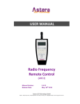
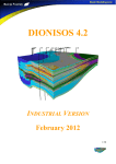
ARC2
radio frequency remote controller
User Manual
Manual Version:
Release Date:
v 3.2.5
July 6, 2010
Astera LED Technology GmbH
Add.: Götzeroth 6, 54483 Kleinich/Germany Tel.:+49(0)6536-355361 Email:[email protected]
This instruction manual is part of the device and persons operating the device must have access to it at any time.
Safety precautions mentioned in the instruction manual have to be observed.
If the device is being sold, this instruction manual has to be included.
Translations
If the device is being sold, this instruction manual has to be translated into the national language of the destination country.
If discrepancies occur in the translated text, the original instruction manual has to be used to solve them tor the
manufacturer has to be contacted.
©2010, Astera LED Technology GmbH
All rights reserved
Kleinich, Germany
Table of Contents
Chapter 1
1 Table of Contents
1 Table of Contents..............................................................................................................................3
2 Safety..................................................................................................................................................4
3 Getting Started...................................................................................................................................5
3.1 Overview......................................................................................................................................5
3.2 LCD Display.................................................................................................................................5
3.3 Introduction..................................................................................................................................6
3.4 Navigation....................................................................................................................................6
3.5 Power Button...............................................................................................................................6
3.5.1 Micro SD card......................................................................................................................6
4 Preset Programs (MEMORY 1-4)......................................................................................................7
4.1 Tap-sync......................................................................................................................................7
5 Editor..................................................................................................................................................9
5.1 Using the Editor...........................................................................................................................9
5.2 Colors..........................................................................................................................................9
5.3 Programs of the Editor.................................................................................................................9
5.4 Adjustments...............................................................................................................................10
5.5 Advanced Adjustments..............................................................................................................10
6 Targeting Lamps..............................................................................................................................13
7 Setup.................................................................................................................................................15
8 Technical Data.................................................................................................................................19
9 Troubleshooting..............................................................................................................................21
10 Appendix.........................................................................................................................................23
10.1 Color Index..............................................................................................................................23
10.2 Customizable Programs...........................................................................................................24
10.3 Color Chaser for Random Modes............................................................................................25
10.4 DMX table for Effect Mode.......................................................................................................26
10.5 Firmware Updating Process ....................................................................................................27
Introduction.................................................................................................................................27
11 Disposal..........................................................................................................................................29
3
2 Safety
Before you operate the unit, read this manual carefully.
Make sure to keep the manual, in case you need to consult
this manual again or you give the unit to another person.
Always make sure to include this manual if you hand out the
unit to another person.
Do not operate the unit in areas where the usage of radio
frequency or mobile phones is prohibited, like for example
in airplanes, or when it may cause interference or danger.
Only qualified personnel may repair this product.
Don't open the case.
This device conforms to CE -or- FCC regulations, see type
label!
It radiates in the 868 MHz or 915 Mhz bands. (See “Error:
Reference source not found“, page Error: Reference source
not found for details.
Always make sure, that your national regulations allow the
use of this device!
Keep batteries away from children. In case of a choking
hazard go to the doctor immediately.
Make sure contacts are clean before you insert batteries.
Watch the polarity.
Only replace with same type of battery, otherwise EXPLOSION can occur.
Don't try to recharge batteries
MAKE SURE TO FULLY CHARGE ALL BATTERY-POWERED
ASTERA LAMPS WHEN STORING THEM.
PARTIALLY CHARGED BATTERIES WILL LOOSE CAPACITY
4
Chapter 3
Getting Started
3 Getting Started
3.1 Overview
Antenna
Display user colors
Navigate through menu,
adjust values
LCD Display
Save/send value
Launch MEMORY
programs 1-8,
back one level
in top level: adjust bpm
Adjust brightness
Adjust fade time
Choose program
Adjust speed
Switch LEDs on/off
Home button: return to top level
Choose user colors
Update all devices in selected groups with current settings.
Choose groups
3.2 LCD Display
Definition of symbols:
(1) - Receiving
(3) - Transmitting
(4) - Inside Editor mode
(5) - Synchronization between units is active
(8) - Battery status
5
3.3 Introduction
Astera ARC2 radio frequency remote control is being used to control Astera's wireless
lamps, wireless controllers and wireless DMX transmitters. The system offers several sets of
predefined programs that can be quickly launched.
For advanced applications the programs can be customized over the Editor (see Chapter 5).
The replaying colors can be defined to fit a theme or corporate identity. These colors can be
used in programs which can be adjusted on speed, brightness and fading effects.
It is also possible, to address, group and synchronize several units and to stretch programs
over several lamps. For example the RAINBOW effect can be stretched over two or more
units displaying the full rainbow spectrum at the same time.
3.4 Navigation
Navigation through the system is done with the top 4 buttons of
the remote control. Enter confirms a value, + and – button
choose a value and Back moves up 1 level in the navigation.
The top level of the navigation contains the 3 sets of pre-defined memory programs
(MEMORY 1 – MEMORY 3) as well as an area to store own programs (MEMORY 4) and the
SETUP. The + and – buttons are used to navigate between them and Enter offers deeper
editing of the MEMORY programs and the setup.
From any point in the navigation, the home button can be pressed to return to the
top level of the navigation. This is especially useful when an inexperienced user
gets lost in advanced settings and is afraid he will alter important settings.
3.5 Power Button
Power Mode: LIGHT ON:
Returns from BLACKOUT to normal operation.
Power Mode: BLACKOUT:
Switches all targeted lamps off and keeps them in
standby, power is reduced.
3.6 Micro SD card
For special functions like saving
programs and firmware update a
micro SD card can be inserted
into the ARC2.
6
Preset Programs (MEMORY 1-4)
Chapter 4
4 Preset Programs (MEMORY 1-4)
For quickly changing the mood of a lamp or setup of lamps, the 24 pre-programed
MEMORY programs can be quickly launched and optionally be customized (see Chapter 5).
To start a MEMORY program, click one of the 8 white buttons while in one of the 3
pre-programed MEMORY tabs on the top level of the ARC2's navigation.
If you not sure in which level you are, press the home button to reach the top level.
In addition to the 3 pre-programmed tabs (MEMORY 1-3) the MEMORY 4 tab provides room
for 8 own creations that can be launched with the white buttons when inside this set.
MEMORY 1 decorative:
This set is suited for basic events, presentations, background
lighting and a a general decorative mood. Also, this is the set
where the home-button leads to.
MEMORY 2 party slow:
This set has pre-programed color transitions for dinner parties,
early hours of disco-nights etc.
MEMORY 3 party heavy:
This set has fast and strong color effects, strobe-effects and
rapid changes between colors. It is suited for dancing events
and to hightlight special parts of a show.
MEMORY 4 user define:
This set is not pre-programed by Astera. Chapter 5 will discuss
how its 8 keys can be programmed with customized colors and
effects. It can be used by event-preparing companies to
prepare special programs for their customers or for quickly l
aunching them during their events.
4.1 Tap-sync
Tap-sync can be used to adjust the speed of the transitions of MEMORY 1-3 programs and programs defined by the user. It can be used to synchronize the lamps'
speed to music that is played but also to the mood of an event.
To tap-sync, while in the top level of the navigation press the tap-sync button twice in
the rhythm you want to synchronize the lamps. If you not sure in which level you are,
press the home button, then press tab-sync twice.
Tap-sync does not affect all types of programs. Only if they use a random color
chaser, tap-sync has an effect.
7
Chapter 5
Editor
5 Editor
5.1 Using the Editor
The Editor is an advanced function that lets you customize the 3 sets of preset MEMORY
programs (decorative, party slow, party heavy). In addition you can save your own programs
onto MEMORY 4 user define if you want to keep the original programs in MEMORY 1-3.
To enter the editor, while in the top level of the navigation in any of the 4 MEMORY
sets, press and hold one of the 8 white button for 2 seconds. Alternatively, when in
the top level navigation choose any of the white buttons, and press press enter to edit
the button's Memory.
5.2 Colors
You can customizing the pre-defined programs with up to 4 colors (C1-C4). All predefined
programs, except RAINBOW take the displayed colors from a four color palette. This palette
can be defined by selecting the colors C1, C2, C3 and C4 and is shown at the top of the remote control when editing the colors. For example, if PROGRAM is set to SIMPLE RUNNING, background color will be C1, and the color of the running pixel will be C2.
There are 3 kinds of colors available for that:
Standard Colors:
red, orange, yellow, green, cyan, blue, magenta, pink, white warm,
color warm, black can be quickly chosen
Index Colors:
256 standard index colors can be chosen when selecting INDEX
COLORS. The colors are listed in Appendix B
User Colors:
If this is not enough choose USER COLORS. Here, you can mix colors
out of the 3 color channels (red, blue, green)
To change colors, enter the Editor, then click any of the C1 – C4 buttons to change
their color. Leave the Editor or click the home button to save their value.
5.3 Programs of the Editor
In addition to colors, there are 20 customizable programs that can be selected when in the
Editor. The programs of the Editor use the colors defined in 5.2 to display static or moving
structures. These structures are formed out of several pixels and can stretch over several
lamps as well. A list of the 20 programs can be found in the appendix.
Note: It is also possible to let the random chaser choose colors for the programs. To use
this feature, see Chapter Error: Reference source not found. Every time the Programs setting is changed, random color chaser will be switched off!
Note: programs are best displayed on a multi-pixel lightsource (e.g. the AL6 series) or
stretched over a group of lamps. If used with a one-pixel lightsource (e.g. AL3-M) only one
color will be shown at a time.
9
Note: Not all programs use all 4 colors (C1-C4). For example the program called TWO COLOR STATIC uses only 2 colors so half of the pixels will be in C1 and the other half in C2.
5.4 Adjustments
The programs you have chosen can be further adjusted in fade, speed and brightness.
To adjust fade, speed and brightness, enter the Editor, then click fade, speed or the
brightness button to change their values. Leave the Editor or click the home button to
save their value.
Fade:
Sets fading transitions between steps of the program in amount of the steptime. If set to 0%, there will be no fading at all, the color will be switched at
once. If set to 100%, the color change will go smoothly from one to the other
color. Any value in between will be a mix of these two settings.
Speed:
Changes the speed of the program. A time between 0,09 seconds and 9
minutes and 21 seconds can be set. This time reflects the duration of the
selected program.: Note: With the change of speed you might get the units out
of sync. In order to re-sync press the Send key or change the program (Chapter
4.1)
Brightness: You can select the Brightness Intensity or the Power Scheme of the lamp.
Both are strongly effecting the battery runtime of the lamps. Choose
INTENSITY to change the brightness of the LEDs between 0% and 100% in
intervals of 10%. Choose Power Scheme to adjust the overall power scheme of
the lamp between HIGH-BRIGHTNESS, NORMAL and MAXIMISE RUNTIME.
Attention: Battery runtime of all the Astera lamps is stated for the Normal power
scheme. Altering the power scheme will lead to different battery runtime.
5.5 Advanced Adjustments
In addition it is possible to adjust a range of parameters if the three basic adjustments are
not enough.
To change additional adjustments of colors and programs enter the Editor then press
the plus and minus buttons choose the setting you want to change and confirm with
Enter.
Stobe Speed:
Adjust frequency and confirm with Enter.
Program Direction:
Choose between forward (left to right), backward (right to left) and
if you want to run the effect only once or repeat it in a loop.
Program Parameter:
Changes parameters depending on the program currently running.
10
Chapter 5
Editor
Blower Speed:
Changes the power of the blower.
Use Random Colors:
When switched to YES it starts the random color chaser which
places random colors on the 4 user color channels(C1 – C4).
Each time tap-sync is pressed the 4 user colors will change.
Random Mode:
Features a range of different chaser modes.
(overview in Appendix 3).
Random Fade:
Fading time of the random chaser.
11
Chapter 6
Targeting Lamps
6 Targeting Lamps
A special button has been assigned to targeting only a selection of lamps that are within the
reach of the remote control. Once one of the Target lamps options has been selected by
choosing ENTER, BACK or the HOME button you will only target those selected lamps until
another value in Target Lamps is chosen.
Target lamps …
..by GROUPS
Each lamp can be set to belong to one of four groups (G1, G2, G3 or
G4). Then each groups can be controlled individually, or groups can be
linked together. If groups are linked, the program pattern stretches
over them. New lamps or reset lamps are set to group 1
Only sequential groups can be linked, for example G1+G2.
It is not possible to link G1+G3.
The GROUP setting can be altered and assigned to lamps in SETUP
using the REMOTE SETUP menu.
..by SET#
Lamps can be assigned to one of 255 possible set-addresses. Also
more than one lamp can be assigned to one set #. In practice, usually
a set of lamps will be assigned one set #. Each of these sets can be
controlled individually.
It is not possible to link sets together, so that programs stretch over
them. Sets can easily be created by using SETUP->CREATE A SET.
..by TAPPING THEM By using this setting, lamps will not receive any information,
unless they are tapped. Tapped means, that their button is
pressed after they indicate that new information is available.
Usually they do this by a short white flash every 1-2 seconds.
..by TYPE
If lamps of different types are used, they can be controlled by
type. For example, if you have AL6 and AL3-S setup, they can
be controlled individually by choosing their type.
..by SERIAL NUMBER
If the serial number of a lamp is known, it can be addressed
directly by entering the S/N into the remote control.
13
Chapter 7
Setup
7 Setup
The setup offers advanced settings that can be done before or after an event like factory reset, forming groups of lamps, calibrating colors and setting a keylock when giving away the
ARC2.
To enter the SETUP menu, while in the top level of the navigation press the minus
button ( - ) until you see SETUP, then confirm with Enter. If you are not sure in which
level you are, press the home button, to get to the top level.
If SETUP does not appear on pressing the ( - ) button, check the KEYLOCK setting!
Create a Set:
Sets combine several lamps which can be addressed at the same time
and arranged in a preferred order to stretch effects over them. Unlike
groups, a huge number of sets (256) can be programmed and targeted
with the Target Lamps button. A set can also be applied to only 1 lamp if
this lamp needs to be targeted quickly.
Create a Chain: Chained lamps will stretch their effects and programs over several lamps.
For example the FLAG RUNNING program can send a pixel running one
AL6 until it reaches its edge, then continue on the next AL6. To allow a
smooth running along the chain, correct positions have to be assigned to
each lamp.
DMX Setup:
Some Astera lamps do not have a LCD-display so the ARC2 can be used
to set them up for DMX usage. Also, Astera lamps with LCD-display might
be easier configured rempotely for DMX because their display cannot be
reached.
For additional information refer to the DMX table in Appendix 4.
DMX Address: Sets the DMX address
DMX Pixels:
All pixels:
Every pixel can be controlled individually
by DMX
Reduced Pixels:
Pixels are combined to aachieve a
fewer pixel count for easier control. Please refer to the
manual of the specific device to see how many pixels
will be present on DMX when this setting is chosen.
One Pixel:
The device can be controlled with only
three DMX channels. All pixels are combined into one.
DMX Tab:
Several different DMX tables can be chosen.
RGB S RGB S..:
For each pixel there are three
channels RGB and one channel stroboscope.
RGB RGB S S..:
All RGB channels are followed by
all stroboscope channels.
Effect Mode Fix:
The 4 user colors are controlled
by one channel per color (generates basic colors).
Effect Mode RGB: The 4 user colors are controlled
by three DMX channels each.
15
Remote Setup:
Strobe:
Single:
One DMX channel is supplied for
the control of the stroboscope function, all pixels
will strobe Identical. When using this setting,
DMX TAB should not be set to RGB S RGB S ..
Multiple:
For each pixel, the stroboscope
can be controlled individually.
Off:
Stroboscope is turned off globally.
DMX Failure:
Sets the behavior of the light in case of an inter
rupted DMX signal.
Hold:
The output keeps unchanged, the
last received DMX frame is displayed.
Emergency Light: If the DMX reception times
out, the light turns white.
Blackout:
If the DMX reception times out,
all light turns black.
Usually all configuration settings, like changing the DMX address,
chain configuration and so on is done directly on the units. This might
not be feasible if several units with the same settings have to be con
figured with the same settings or a unit is not equipped with a LCD-dis
play.
Remote Group
Input Select
AC Failure
Assigns lamps or sets into any of the 4 groups.
If not programmed, all lamps are set to group 1.
If a lamp has several input signals (for example it is
connected to a DMX cable but should be targeted
by the ARC2) the preferred input signal can be
defined
XLR DMX
for the signal of wired DMX
Wireless DMX for the signal of wireless DMX
Remote Control for the radio signal of the ARC2
Standalone
to keep the last input signal (for
example 1 color) until another in
put source is chosen.
Auto
Automatically chooses an input
source
Emergency Light If no AC signal is detected, the
light turns white.
No Action
Blackout If no AC signal, all light turns black.
Manual White Calibration:
You can enable automatic white calibration or
manually adjust the red, green and blue levels that
are used to display white color.
SD Card
Saves the colors and effects that have been assigned to the white keys.
Choose a name with the plus, minus & Enter buttons. Back/Tap-sync jumps to the next set of letters,
← deletes, >> stores the keys with the chosen
name.
Copies the stored keys to the ARC2's memory.
Backup Keys
Restore Keys
16
Chapter 7
Setup
Firmware update
The ARC2 can be used to update the firmware of
most Astera lamps and controllers that are
equipped with a RF receiver (Antenna).
Please refer to the Firmware update manual in
appendix 10.5. for detailed instructions.
Test Radio
The Test pattern Color Change allows you to test the radio frequency
range conveniently by walking away from a lamp just 8-16m while holding the ARC2. If the Test Radio is activated, the remote switches to minimum output power and transmits a color change, change every second.
If the color change works in that range, lamps and remote are ok.
You might need to move the remote around a little to avoid interference.
Radio Pin:
The Radio Pin makes it possible for different customers to operate their
lamps at the same place without influencing other lamps. The 4-digit pin
can be set to a unique value and paired with selected lamps. To activate
the radio pin, choose a pin on lamps and remote control, then press PAIR
WITH LAMPS.
Factory Reset:
Selecting THIS REMOTE will reset all settings including keylocks and all
MEMORY programs.
Resetting LAMPS will ask you to tap individual lamps to select which of
the lamps in range you want to reset.
For event rental companies a factory reset of the ARC2 remote should be
done after each rental job to avoid misleading settings from customers.
17
Chapter 8
Technical Data
8 Technical Data
Environment
Temperature (operation)
5 °C – 40 °C
Temperature (transport)
-25 °C – 55 °C (70 °C for 24h)
Relative Humidity
0 - 95%
Altitude
up to 2000m above sea level
Site
interior
Battery
2x 1,5V AA (LR6)
Measurements
Unit Size in mm
L183mm x W62mm x H31mm
Unit Size in inch
L7.2” x W2.4” x H1.2”
Unit Weight in gram
160g
Unit Weight in pound
0.35lb
Radio Frequency
RF Coverage Range
50m up to 300m
Frequency EU & EFTA
868.000 MHz – 869.750 MHz
Frequency US, Canada, Australia, New Zealand
902MHz – 928 MHz
WARNING
The user must make sure, that the national regulations
allow the operation of this RF device!
If this is neglected, serious harm may occur!
19
Chapter 9
Troubleshooting
9 Troubleshooting
Faulty condition
Cause
Troubleshooting
Units are out of sync
Adjustment of the SPEED
Press SEND button or change
parameter can cause deviation
PROGRAM.
between the units; also the units will
drift out of sync after a few hours.
Units behave incorrectly
Due to the vast number of settings, Do FACTORY RESET on units
one can not always predict behavior and/or remote control.
of the units, if setup was already
done earlier.
One/a few units don't play the
correct program, even if it was set
up earlier.
If a unit is powered up after the light Press SEND button on remote
scene was setup with the remote
control to update the unit.
control, if will not work correctly.
A unit is flashing in blue or other
color all the time and not accepting
any command.
It might be in BLUE MODE.
Hold down the button until the
flashing stops.
One/a few units don't react on the
remote control.
You might be targeting the wrong
lamps
Check TARGET LAMPS and select
the set you have programmed the
lamps in or make sure you are
sending to all 4 groups to target all
lamps.
Units will go out of battery after only Some units last only 8 hours with
6 hours of operation.
COLD WHITE, if the LED POWER
is set to NORMAL. For HIGH
BRIGHTNESS the runtime may be
shorter than 8 hours.
Adjust LED POWER and/or see
manual of the unit.
The display of a unit is showing
BLACKOUT, and there is no light
output.
Either the unit is set to BLACKOUT
mode, or DMX-FAILURE/AC
FAILURE is set to BLACKOUT and
one of these conditions persist.
Press I/O on remote control and set
to DISABLED.
Check settings of DMXFAILURE/AC FAILURE.
Maybe do FACTORY RESET.
Each time I press the tap-sync
buttons the displayed colors are
changing.
You have switched Random Colors
on.
Enter the Editor, select USE
RANDOM COLS, then select NO.
21
Appendix
Chapter 10
10 Appendix
10.1 Color Index
23
10.2 Customizable Programs
Name
ONE COLOR STATIC
TWO COLOR STATIC
THREE COLOR STATIC
FOUR COLOR STATIC
ONE COLOR FADE
Light Effect
All pixels show the same color
Same as ONE COLOR STATIC, but
not all pixels show the same color,
they are divided into 2, 3 or 4 parts.
All pixels show the same color, but
the color changes between all four
USER COLORS.
TWO COLOR FADE
Same as ONE COLOR FADE, but
not all pixels show the same color,
THREE COLOR FADE
they are divided into 2, 3 or 4 parts.
FOUR COLOR FADE
All pixels have C1 color, except one,
SIMPLE RUNNING
that is running over them with C2.
DOUBLE RUNNING
Same as SIMPLE RUNNING, but two
pixels
are
running
over
the
background, in opposite directions.
TWO COL RUNNING
Same as DOUBLE RUNNING, but
the two pixels are of different color.
A “flag” consisting of three color
FLAG RUNNING
stripes
is
running
over
the
background.
DOUBLE FLAG RUNNING Same as FLAG RUNNING, but two
flags are running in opposite
directions.
The color of all pixels is changing
SPIRAL 4 COLORS
pixel by pixel from one color to the
next. If the geometry of the unit
allows it, the direction is circular.
SPIRAL 2 COLORS
Same as SPIRAL 4 COLORS, but
the movement starts at both and in
opposite directions, and moves back
after all pixels are changed.
A moving rainbow is shown on the
RAINBOW
units.
A flickering fire-like effect is
FIRE
displayed. C1 is the background
color, randomly pixels flash and
flicker with C2.
The rotor programs are much like the
ROTOR
FADE programs, but if the units are
of tower-like shape, then a clockwise
running rotor can be seen.
ROTOR SPLIT 2
Same as ROTOR, but two rotors in
opposite directions are running.
ROTOR SPLIT 4
Same as ROTOR, but four rotors in
opposite directions are running.
24
Used colors
C1
C1 C2
C1 C2 C3
C1 C2 C3 C4
C1 C2 C3 C4
C1 C2 C3 C4
C1 C2 C3 C4
C1 C2 C3 C4
C1 C2
C1 C2
C1 C2 C3
C1 C2 C3 C4
C1 C2 C3 C4
C1 C2 C3 C4
C1 C2
none
C1 C2
C1 C2 C3 C4
C1 C2 C3 C4
C1 C2 C3 C4
Appendix
Chapter 10
10.3 Color Chaser for Random Modes
RANDOM MODE[7..0]:
7..6: strobe-override mode
00: strobe not overridden
01: strobe disabled for C2, C4
10: strobe disabled for C2, C3
11: stribe disabled for C1
5..4: timeline parameters
00: at each step all colors change
01: colors change one by one
10: one step colored, next step black
11: three steps colors, one step black
3..2: color-override mode
00: colors not overridden
01: C1 is always black
10: C1 is always C1
11: C1 and C3 are always C1
1: color-wheel effect
0: color-table: 0 == color table, 1 == user colors
50: color-wheel effect, color table is used.
25
10.4 DMX table for Effect Mode
Channel
EFFECT MODE FIX
EFFECT MODE RGB
1
INTENSITY
2
STROBE
3
PROGRAM
4
SPEED
5
FADE
6
DIRECTION:
0..63: FFW+LOOP
64..127: FFW
128..190: REW
191..255: REW+LOOP
7
SIZE:
defines the virtual size of the program in groups. For example if SIZE is set to 2
groups, only half of the program is shown on the unit.
0..63: 1 group
64..127: 2 groups
128..191: 3 groups
192..255: 4 groups
8
OFFSET:
if SIZE is set to >1 group, the units pixels can be shifted within the virtually larger
program. Increasing the OFFSET parameter scrolls the position of the unit within
the virtual large program.
9
RESTART PROGRAM:
if value is changed, the program starts again from the beginning (useful if
DIRECTION is not set to loop)
10
INDEX COLOR 1
COL 1 RED
11
INDEX COLOR 2
COL 1 GREEN
12
INDEX COLOR 3
COL 1 BLUE
13
INDEX COLOR 4
COL 2 RED
14
COL 2 GREEN
15
COL 2 BLUE
16
COL 3 RED
17
COL 3 GREEN
18
COL 3 BLUE
18
COL 4 RED
20
COL 4 GREEN
21
COL 4 BLUE
26
Appendix
Chapter 10
10.5 Firmware Updating Process
Introduction
The Firmware Updater can be used to update the firmware of most of most Astera lamps
that are equipped with a RF receiver (Antenna).
The firmware version of the controllers must be at least 2.5.0 to support update by RF.
Preparation
•
The .FRM file of the new firmware must be downloaded from www.asteraled.com/downloads . This file must be copied to a micro-SD card (also known as
Trans Flash card) that is formatted with FAT16 or FAT32. Care has to be taken, that
the file is really dedicated for the controller to update. There might be different
hardware releases of the same type controller. If the file does not fit, the lamp will not
accept it.
•
Slide the micro-SD card into the ARC2.
•
Arrange the lamps that are to be updated and the ARC2 to a distance of 0.5-5m.
Make sure, that no disturbances between the antennas can occur during update. If
the transmission is interfered, controllers might get stuck during update. If this
happens, they are unusable until the update is completed. This can be done in two
ways:
1. Do the same update again with the Firmware Updater, not cycling power of the
stuck controllers. They will pick up again at the position they lost the transmission
before.
2. Power off the controllers and start the whole update again.
Update Process
1. Power on the ARC2 and make sure the SD-Card is inserted.
2. Choose SETUP > SD card > Firmware Update > Choose File
3. Choose suitable file with + and – keys, then press Enter
4. Go to “UPDATE FIRMWARE” and press ENTER
5. The LCD will show “SENDING INIT....”. While the init sequence is sent, power up all
controllers you like to update. They will not power up as usual, but stay in the update
routine. Usually they will appear as if they are not powered up while the update is in
process (see table below how each unit reacts). If a controller powers up as usual,
either the wireless link is bad or the .FRM file does not fit the controller.
27
6.
When all lamps and controllers are prepared, press the ENTER key to start
the update.
7.
The LCD will count up, wait until the update is completed. Normal times are:
4 minutes for 32x processors and 8 minutes for 64x processors.
The update can be aborted by pressing ENTER for 2 seconds or the ON/OFF button shortly.
8.
If the updated worked, the controllers will power up again, and behave as
usual. If a controller does not power up, the update got stuck. Then either
directly start the update again by selecting “UPDATE FIRMWARE”, or
power off the controllers and start the whole process again.
List of Lamps and Controllers
Product
Remarks
AL5
Update can only be done while the device is running on AC supply.
Switch off, then plug in the power cord while “SENDING INIT” is
displayed on Firmware Updater. The LCD and LEDs will stay dark
until the update is completed.
AL6
AC2
AC4
ART1
AL1
AL3
Power up normally while “SENDING INIT”, if present, a flashing blue
power-LED indicates that the update is in progress.
AL7
AL8
ARC2
28
Insert batteries while “SENDING INIT”. A flashing LCD backlight
indicates that the update is in progress.
Chapter 11
Disposal
11 Disposal
Follow local ordinances and/or regulations for disposal!
PACKAGING:
The unit is shipped in protective packaging.
This packaging can be recycled!
UNIT:
Don't throw the unit into the garbage at the end of its lifetime.
Make sure to dispose is according to your local ordinances and/or regulations, to avoid polluting the environment!
BATTERIES:
Don't throw empty batteries into the garbage!
Bring them to a collecting point for used batteries!
29