1
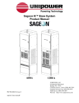
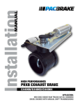
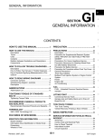
-!.5!,
)NSTALLATION
P-80 And P-80A
%.').%"2!+%
0APPLICATION
$ETROITDIESELENGINESMODELYEAR
,ITER3ERIES
0!APPLICATION
$ETROITDIESELENGINESMODELYEAR
,ITER3ERIES
P-80 and P-80A Engine Brakes
VERY IMPORTANT APPLICATION INFORMATION
Please read carefully as incorrect application will cause engine damage.
1
Before Starting
Use the following information to determine the correct Pacbrake for your application.
E n g i n e Ye a r
Identification Characteristic
Pacbrake Model
1999
2000
Roller for master piston on injector rocker arm
Pocket for master piston on injector rocker arm
81.0 mm injector setting
Pocket for master piston on injector rocker arm
82.1 mm injector setting
P-63C
P-80
2001
P-80A
Check the engine serial number and engine build date PRIOR to installing this Pacbrake engine brake.
P-63C model fits engines manufactured before 12/15/99
P-63C model fits Freightliner engines below 06R566178
P-63C model fits OEM engines below 06R566302
P-80 model fits engines manufactured 12/15/99 to 8/10/00
P-80 model fits Freightliner engines above 06R566178
P-80 model fits OEM engines above 06R566302
P-80A model fits engines manufactured 8/10/00 to 9/30/02
P-80A model fits engines with 82.1mm injector lash
These new 2000 model year engines are built starting late December 1999 and differ from the 1999 model year engine by the
elimination of the engine brake’s dedicated roller on the injector rocker arm. The 2000 model year engine has a machined pocket
in the injector rocker arm to replace the roller. Installing the incorrect engine brake will cause engine and engine brake failure.
Check the engine’s option label on the valve cover for injector setting information. Injector settings relate to the engines
camshaft. The only way to visually confirm which camshaft the engine has is by checking the injector setting on the options label.
See above. Misapplication will cause engine damage. If unsure please contact Pacbrake Factory @ 1-800-663-0096.
DDEC III and DDEC IV Applications
Note: Two different engine brake activation circuits are available for Series 60 engines. The engine ECU has an optional circuit
to control the engine brake. Use a Prolink diagnostic tool to determine if the circuit is turned on. If the circuit is not turned on for
engine brake enable, it can be reprogrammed by a Detroit Diesel Dealer for a service charge. When using this activation circuit, if
no under cover wiring exists, use Pacbrake Kit P80155.
An optional ECU bypass system P60154 is available through Pacbrake distrribution. This system uses a foot switch and a service
brake pressure switch to enable the engine brake, the engine ECU does not need to be reprogrammed for this system. P60154 kit
includes all the necessary components for electrical installation.
I N S TA L L AT I O N M A N U A L - L2021
PG. 2
P-80 and P-80A Engine Brakes
2
Before starting, check that the kit contains everything
shown in this photo.
CAUTION: Care should be taken when handling housing. Dropping housing could cause leg damage/failure
which is not covered under warranty.
Tools Required
3/8 Drive ratchet
1/2 Drive ratchet
Inch/pound torque wrench
3/8 Torque wrench accurate @ 25 lb. ft.
1/2 Torque wrench accurate @ 100 lb. ft.
Speeder handle
1/2 Breaker bar or flex bar
36mm Socket
18mm Deep socket 1/2 drive
IOmm Socket 3/8 drive
IOmm Hex driver
#I Phillips screw driver
5/32 (4mm) Allen wrench
3/4” Box End wrench
9/16” Box End wrench
3/4” Crows foot
3/8” Extension 3”
3/8” Extension 6”
3/16” Extension 6”
Flat blade screw driver
Wire cutters
Compressed air/air nozzle or suitable device
Threebond liquid gasket PN# 1217F
General use
General use
Valve cover bolts
Paclash adjustment
Hold down capscrews
Housing capscrews & nuts
Rocker shaft capscrews removal
Rotate engine
Rocker shaft capscrews
Valve cover capscrews
Pacbrake housing capscrews
Solenoid terminal
Paclash adjustment
Paclash adjustment
Paclash adjustment
Torque paclash
With crows foot
Valve cover capscrews
Valve cover capscrews
Breather tube hose clamp
Tystraps
Blowing out bolt holes
Valve cover sealant at bearing caps if required.
Additional tools for engines which are not factory wired:
13 mm Socket
Cylinder head wiring connector
Needle nose pliers
Removal of plugs in connector
3
Stamped on the side of the engine block is the engine serial
number and model number. (Sample 6067MK60) The first
letter in the engine model number indicates displacement.
The second letter indicates the type of electronic control
system. If unsure, attain the engine serial n
I N S TA L L AT I O N M A N U A L - L2021
PG. 3
P-80 and P-80A Engine Brakes
4
Thoroughly clean the top of the engine and remove the valve
cover.
NOTE: The valve cover is installed with a silicone
adhesive on both sides of the front and rear bearing caps. Take care not to stretch the gasket when
removing the cover. (See page 3 for sealing material
if required). If your engine is prewired, locate the
three dedicated wires and omit the following steps 5
through 15.
Engine Is Not Prewired
5
Remove the wiring harness mounting flange from the rear of
the cylinder head.
6
There are four spare holes through the harness grommet
which are sealed with plastic plugs. Pulling outward, remove
any two of these plugs.
7
Insert both wires of the Pacbrake ‘through head harness’
through the grommet from the outside.
NOTE: In trucks with limited access at the rear of the
cylinder head, it may be easier to slide the grommet
out of the head.
I N S TA L L AT I O N M A N U A L - L2021
PG. 4
P-80 and P-80A Engine Brakes
8
Route the wires alongside the Electronic Unit Injector (EUI)
harness and adjust the length so the terminal ends are
between cylinders 5 and 6.
9
Lay the two wires in the convoluted conduit and replace the
harness mounting flange.
10
Bury the wires within 1” of the Weather Pack connector and
tape around the conduit to keep in place.
NOTE: By using this same connector and wire positions, the Pacbrake harnesses are completely compatible with the Detroit Diesel engine harness and the
VOEMs vehicle harness.
NOTE: If installing a P60154 kit, follow the instructions provided in the P60154 kit.
11
ENGINES WITH ENABLE CIRCUIT TURNED ON ONLY
Locate the red (561) and orange (562) wires terminating in
the Metri-Pack plug. This is located in the harness on the
drivers side of the engine just below the intake manifold,
above the starter.
12
ENGINES WITH ENABLE CIRCUIT TURNED ON ONLY
Remove the black protective cap and connect to Pacbrake
harness previously installed in step 7..
I N S TA L L AT I O N M A N U A L - L2021
PG. 5
P-80 and P-80A Engine Brakes
13
ALL INSTALLATIONS WITHOUT FACTORY WIRING
The through head harness must now be connected to the
under cover harness, P/N P80048. As both halves of the connector are preassembled, simply insert the plain white wire
into the hole on the same side as the other plain white wire.
The remaining wires both have black shrink tube markings.
14
ALL INSTALLATIONS WITHOUT FACTORY WIRING
This connector is polarized and may now be parted and
reconnected without losing correct brake sequencing.
15
ALL INSTALLATIONS
Secure the complete Pacbrake harness to the EUI harness
with plastic ties.
Note: Use only the ties supplied in the kit which are
temperature stabilized and will not deteriorate due to
heat.
I N S TA L L AT I O N M A N U A L - L2021
PG. 6
P-80C Engine Brakes
Brake Housing Installation
17
Evenly remove the three rocker shaft capscrews and nut for
each rocker shaft assembly as shown in illustration — numbered 1,2, 3 and 4 then number 5, 6, 7 and 8. Discard the
capscrews and save the nuts for reuse later.
NOTE: It is a recommended procedure to check the torque of the
studs at #1 and #8 position. Once the nuts are removed, torque to
101-116 N•m (75-86 lbs. ft) as per DDC procedure.
CAUTION:
air pressure or procedure
a suitable suction
devicetorque
remove
NOTE:
It Using
is recommended
to check
trapped
oil from#1
mounting
holes
2 through
7 and
9 throughtorque
14.
on
the studs
and #8.
Once
nuts are
removed
to 101-116 N•m (75-96 lb. ft) as per DDC procedure.
CAUTION: Using air pressure or a suitable suction
device remove trapped oil from mounting holes 2
through 7 and 9 through 14.
18
Place the 6 spacer tubes on the exhaust manifold side of the
engine in locations 9 through 14 on previous diagram.
19
Place the special hardened washers on each of the 12 Pacbrake capscrews supplied.
I N S TA L L AT I O N M A N U A L - L5590
PG. 7
P-80 and P-80A Engine Brakes
19
Locate the 6 longer capscrews, these go through the center
positions of the housing to secure the housing and rocker
shaft. Lubricate and install three of these allen head capscrews through the center holes in each housing. Carefully
position the front engine brake housing over cylinders 1, 2
and 3 using the front Detroit stud as a guide. Repeat on the
rear housing using the rear stud as a guide.
20
Install Pacbrake washers on the Detroit rocker studs then
loosely install the two rocker hold-down nuts removed
earlier.
21
Loosely install the six shorter allen head capscrews on the
turbocharger side of the Pacbrake housing.
Note: Ensure that each master piston link is located
over its rocker arm socket.
22
Carefully run the capscrews and nuts down evenly in the
torque sequence below using hand tools only. Do not use
an impact wrench as the housings must be tightened down
evenly.
I N S TA L L AT I O N M A N U A L - L2021
PG. 8
P-80 and P-80A Engine Brakes
23
Torque the hold-down cap screws and nuts to
55 N•m (40 lb. ft.) in the sequence shown below.
Then to 136 N•m (100 lb. ft.).
Double check all bolt torques.
24
Attach the three wires to the solenoids. Using the plastic ties
provided secure the harness away from all moving parts.
Wires may be tied to spacer tubes. Use only the ties provided
as they are temperature stabilized and will not deteriorate
due to heat.
CAUTION: Route wires on front housing as shown by
arrow.
25
Slave Piston Adjustment
Loosen all twelve slave piston adjusting screws and locknuts. Determine which cylinders have clearance between
exhaust rocker arm adjusting screws and valve stems,
indicating that the exhaust valves are fully closed. There
are usually four cylinders in this condition regardless of the
crankshaft position.
NOTE: Both screws on each cylinder having closed
valves may be adjusted.
I N S TA L L AT I O N M A N U A L - L2021
PG. 9
P-80 and P-80A Engine Brakes
26
Slave lash may now be adjusted on all cylinders which have
clearance between the exhaust rocker adjusting screw and
valve stems. Turn the slave adjusting screw clockwise to
establish zero exhaust valve lash. Once zero lash is determined, turn screw an additional 1/4 turn to squeeze out any
trapped oil, then back screw out to zero exhaust valve lash.
IMPORTANT!
The term zero lash used in the procedure refers to the
clearance between the slave piston and the exhaust
valve adjusting screw.
For P-80 Only: USE CAUTION when adjusting the slave
lash, the adjusting screw has a spring loaded piston,
exercise caution as the piston in the adjusting screw
must be collapsed when final adjustment is performed.
The P-80A has smaller 3/8” thread solid brake adjusting screws.
27
From this position (zero lash), turn the Allen wrench counterclockwise exactly 1/2 turn and torque the locknut to 35 N•m
(25 lb. ft.). This method gives the correct slave piston clearance for P-80 of .025” and .032” for P-80A. Repeat this
procedure on all cylinders on which the exhaust valves are
closed. Bar the engine over approximately one revolution
and adjust the remaining cylinders which now have clearance between the exhaust rocker adjusting screw and valve
stems. Double check that slave lash has been adjusted on all
12 Pacbrake adjusting screws.
P-80 models use a 1/2” NF thread to achieve a Slave
P-80 models
use a 1/2” NF thread to achieve a Slave Lash of .025”
Lash
of .025”
P-80A
models
useuse
a 3/8”
NC thread
to achieve
Slave Lash
of .032”
P-80A models
a 3/8”
NC thread
to aachieve
a Slave
Lash of .032”
CAUTION:
Do not overtorque slave adjusting screw locknut.
CAUTION:
Double
all torques
and adjusting
wiring prior screw
to reinstalling
the valve
Do
notcheck
overtorque
slave
locknut.
cover. Usecheck
Threebond
sealant atand
front
and rear
bearing
caps at valve
Double
all torques
wiring
prior
to reinstallcoverthe
installation.
TorqueUse
valve
cover boltssealant
as per DDC
ing
valve cover.
Threebond
at service
front manual.
and rear bearing caps at valve cover installation.
Torque valve cover bolts to 150 lb. in.
as per DDC service manual.
I N S TA L L AT I O N M A N U A L - L2021
PG. 10
P-80 and P-80A Engine Brakes
Engines using P60154, follow the instructions provided in the P60154 kit.
28
Control System DDEC IV
ENGINES WITH ENABLE CIRCUIT TURNED ON ONLY
Some DDEC IV engines have the engine brake wiring installed at the factory. If not, follow the instructions below.
Locate the 30 pin connector at the rear end of the DDEC IV
ECM. This is the Vehicle Interface Harness (VIH).
NOTE: Some DDEC IV engines may not have the ECM
programmed for engine braking. This may be verified using a Diagnostic Data Reader. If any of the ECM
input switches; K2, K3, S3 or T3 read NONE, then the
vehicle should be taken to a DDC dealer to have these
switches enabled.
29
Note the color and/or number of the two wires originating at
the K2 and K3 terminals of the VIH connector. They are both
on the top row, K2 is in the center and K3 is the closest one
to the engine.
These two wires terminate behind the dash and may be
grouped with a third wire connected to battery ground.
30
Mount the two dash switches and connect the three wires as
shown in the DDEC IV wiring schematic.
CAUTION: Ensure that ONLY the negative ground side
of the electrical system is input to terminals K2 and
K3 via the dash switches OR DAMAGE TO THE ENGINE
ECM WILL RESULT.
I N S TA L L AT I O N M A N U A L - L2021
PG. 11
P-80 and P-80A Engine Brakes
DDEC IV Wiring Schematic - P-80/P-80A
WITH ENABLE CIRCUIT TURNED ON ONLY
/N/FF3WITCH
(I-ED,OW3WITCH
*UMPERWIRE
ANDTERMINALS
SUPPLIED
4O+TERMINAL
%#-
"ATTERY'ROUND
4O+TERMINAL
%#-
%LECTRONIC
#ONTROL-ODULE%#-
0INCONNECTOR
5NDERTHECOVER
-ETRI0ACK
#ONNECTOR
&RONTOF
ENGINE
"
!
The Metri-Pac connector located above the starter is the same as previous 1999 engines.
Orange wire is for the LOW position, red wire is for the MED position, both wires activated for the HIGH position.
NOTES:
• One of the features of the DDEC IV control system provides a progressive brake feature which is used when the vehicle is in
cruise control.
• The level of engine brake (low, med., high) selected via the dash switches will be the maximum amount of engine brake the ECM
allows.
• Also, using the foot brake or clutch during this procedure disables cruise control and progressive engine brake feature.
I N S TA L L AT I O N M A N U A L - L2021
PG. 12
Pacbrake Company
toll-free: 800-663-0096
phone: 604-882-0183
fax: 604-882-9278
e-mail: [email protected]
Internet: www.pacbrake.com
Canada: 19594 96 Ave. Surrey BC V4N 4C3
USA: 250 H St. Box 1822 Blaine WA 98231-1822
Pacbrake exhaust brakes are protected by law.
U.S. patents 5,445,248. Patents pending. Pacbrake and Direct Mount are registered trademarks
of Pacbrake Company. Other trademarks used herein are property of their respective holders.
Printed in Canada L2021_rev2.03.22.10