1
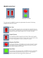
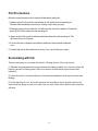
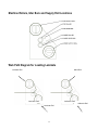
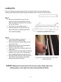
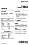
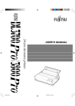
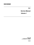
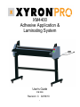
XM4400
Adhesive Application &
Laminating System
User’s Guide
P/N 3355
Revision: C 02/09/10
1
Table of Contents
Introduction………………………………………………………………………………………
3
Technical Specifications……………………………………………………………………….
3
Warnings…………………………………………………………………………………………
3
Contents of the XM4400 machine box……………….………………………………………
4
Unpacking and assembling the cart………………………………………………………….
4
Unpacking and positioning the machine…………………………………………………….
4
Cart Assembly – Exploded View / Parts Table………………………………………………
5
Cart Assembly Instructions……………………………………………………………………
6
Securing Machine to Cart………………………………………………………………………
10
XM4400 control panel…………………………………………………………………………..
11
Film Pre-Cautions………………………………………………………………………………..
12
Economizing with Film…….……………………………………………………………………
12
Machine Rollers, Bars and Supply Roll Locations …….…………………………………
13
Web Path Diagram for Loading Laminate……………………………………………………
13
Loading laminate film………………………………………………………………………….
14
Troubleshooting tip for loading laminate………………………………….………………..
16
Caring for your rollers………………………………………………………………………….
16
Laminating items……………………………………………………..…………………………
17
Cutting Laminate…….………………………………………………………………………….
18
Laminating Multiple items……………………………………………………..………………
19
Machine troubleshooting……………………………………………………………………..
20
Machine Exploded View……..………………………………………………………………..
22
Maintenance Schedule………………….…………………………………………………….
22
Supply Rolls / Optional Equipment ………………………………………………………….
22
Machine Cleaning Points……….……………………………………………………………..
23
Machine Cleaning Instructions……………………………………………………………….
23
Replacing Supply Rolls ……………………………………………………………………….
24
Technical Support ……………………………………………………………………….…….
25
Product Warranty / Cautions / Exclusions ……………………………………………………
25
Contact Xyron………………………………………………………………………..…………..
25
2
Introduction
Thank you for purchasing the XyronPro XM4400 Adhesive Transfer and Laminating System. We are
sure you will find this laminator to be useful, reliable, and easy-to-use. The XM4400 is designed to apply high
quality, adhesive or bubble free laminate to posters, banners, and any other visuals up to 42 inches wide and up to
300 feet long that you want to protect for future use. The machine and supplies are compatible with all types of
computer-printed media including laser, inkjet, color and thermal in a wide range of material sizes.
Technical Specifications
Mechanical Electrically Driven cold lamination 110V @ 2 Amp (max)
Supplies See page 17 for detailed supply roll information
Electrically driven cold lamination 110V @ 2 Amp (max)
Document size (max) 42” (W) x 300 feet (L) [108 cm (W) x 91.4 m (L)]
Laminate total thickness 0.004 inches (0.1 mm)
Document thickness 0.0 to 0.10 inches (2.54 mm)
Machine footprint [Inches] 50.5" L x 11" W x 14.5" H
Machine footprint [cm] 128.3 cm (L) x 27.94 cm (W) x 36.83 cm (H)]
Stand footprint [Inches] 49.5" L x 22" W x 28" H
Stand footprint [cm] 125.7 cm (L) x 55.88 cm (W) x 71.12 cm (H)
Machine weight 155 lbs. (70.45 kg)
Warnings
1. Read and understand the Operation Manual and all safety labels before operating this machine.
2. Only a trained person is to be permitted to operate this machine. Training should include instruction
in operation under normal conditions and emergency situations.
3. This machine is to be serviced only by trained and authorized personnel. Follow lockout procedures
before servicing.
4. Never reach into the machine for any reason unless the machine is at a COMPLETE STOP.
5. Never leave the machine stopped in such a manner that another worker can start the machine while
you are working on or within the machine.
6. Never change or defeat the function of electrical interlocks or other machine "shutdown" switches.
7. Before starting this machine, check that:
- All persons are clear of the machine.
- No maintenance work is being performed on the machine.
- All guards are in place.
- All laminate rolls are well secured in the side plate slots.
- The machine is free of paper scraps, wraps and jams.
8. Equipment has pinch points that can cause injury. Keep hands, loose clothing, jewelry or hair away
from rollers during loading of the film.
9. Cutter has an exposed blade that could cause personal injury if contact is made. Use caution when
using or handling the hand held cutters.
10. Electric Shock Hazard. Do not open machine covers. No user serviceable parts inside covers.
11. The socket-outlet shall be installed near the equipment and shall be easily accessible.
3
Contents of the XM4400
The XM4400 is fully assembled and requires minimal set up other than unpacking the machine,
assembly of the cart, mounting the machine to the cart, plugging it in, and loading the film. You will find
the contents of the box to include:
1. XM4400 machine
2. In-Feed tray with paddle [3309]
3. Un-assembled cart components
a. (2) Rectangle Cross Bar [3346]
b. (2) Cart frame end pieces [3806]
c. (4) 1/4"-20" x 2.25" hex head bolts [3330]
d. (4) 1/4" washers [2143-02]
e. (4) 1/4" split washers [2189-04]
f. (4) 5/16"-18 Nylock nut – Black [3803]
g. (4) 5/16" Washer – Black [3804]
h. (2) 4” Swivel Caster [3808]
i. (2) 4” Swivel Caster W/ Brake [3809]
j. (4) Caster Mounting Bolt, 5/16-18 X 2.75" [3807]
k. (4) Caster Shoulder Bolt, 2.225" X .371" [3812]
l. (4) Lock Nut Nylon, .371" [3814]
m.
4. Tools included
a. (1) 3/16” Hex wrench for assembly [3352]
b. (1) 1/8” Hex wrench for sprocket / chain adjustment [3354]
5. Warranty card [XLT-PRO-01]
6. (2) Hand held cutters [3351]
7. XM4400 User's Guide [3355]
Unpacking and Assembly of the Cart
It is necessary to have two people unpack and assemble the cart and laminator. Unpack the contents,
lay them out on a table or floor and check vs. the contents list above. If you are missing any items,
please contact customer service [See contact information in the back of this manual].
.
4
XM4400 Cart Assembly
Exploded view of Cart Assembly: Shows Cross bar assembly and hardware
5
Cart Assembly Instructions
1. The cart assembly is begun by assembly of the right side assembly frame end to the 2 cross bars [3346]
with a 2 ¼” Hex Head bolt [3330] with washer [2143-02] and split lock washer [2189-04]. Install the upper
cross bar by Inserting the metal dowel pin into the pilot hole and then inserting and locating the
threaded bolt into the screw hole. Tighten the bolt using the 3/16” Hex wrench for assembly [3352] and
then assemble the bottom cross bar. See figure 1 / 2. Then fit and assemble the cross bars to the left
side frame end in by inserting the metal dowel pin into the pilot holes of both the upper and lower cross
bars and tightening until secured.
Figure 1: Cross bars assembled one side at a time
Figure 2: Bolt with washer and lock washer
2. Once the cart frame has been assembled, turn the frame upside down in order to mount the caster
frames and caster wheels.
3. The caster components [mounting frame, wheel and hardware are packaged together. See figure 3.
Figure 3: Caster components and hardware
6
4. To assemble the caster wheel frame, begin by mounting the caster frames to the cart frame ends by
threading the cart threaded stem into bottom weld nut of the cart frame ends. See figure 4 / 5.
Figure 4/5: Using hardware supplied, secure caster frame to cart
5. Thread the caster bolt stem up through the weld nut on the bottom side and through hole on the top side
of the new cart frame ends. Secure using a Black Washer and Black Nylock nut. The threaded stem
must be flat or flush on the top of the nylock nut. Do not over tighten the Nylock nut as this will deform
the cart frame. See figure 6
Figure 6: Nylock nut thread position – flush / flat at top of nut - Critical
DO NOT OVER TIGHTEN THE NYLOCK NUT!!
OVER TIGHTENING CAN RESULT IN DEFORMATION OF THE CART FRAME.
7
6. Next assemble the casters by inserting the wheel into the caster frames and secure with the caster bold
and nut which were provided with the casters. See figure 7 / 8
Figure 7 / 8: Caster wheel assembled
7. Next assemble the casters by inserting the wheel into the caster frames and secure with the caster bold
and nut which were provided with the casters. See figure 9 / 10
Figure 9: Non-Brake caster mounted
Figure 10: Brake caster mounted
Note: Left side of stand has locking caster in front and non-locking caster in back.
8. Once assembly is completed, insert the end caps [3331] into the cart frame.
8
Assembled Machine Cart
Unpacking and Positioning the Machine
To begin unpacking, remove the packing from around the machine. CAUTION: The machine weighs
155 Lbs [70.45 Kg], have someone assist you in lifting the machine onto the mobile stand. Please
lift from under the ends of the machine. DO NOT LIFT USING ANY OF THE ROLLERS.
Remember when lifting to bend your knees and keep your back straight to prevent over stressing and
possible injury to your back. Remove the packaging from around the machine.
Position the machine ends over the top bars on the cart. On the underside of each end of the machine
there are two threaded holes. These holes need to align over the holes in the top bars of the cart.
Install the four bolts up through the holes in the bars and into the threaded holes. Turn the bolts in as
far as possible by hand. Then tighten all four bolts with the supplied Allen wrench.
9
Securing Machine to Cart
The machine should be placed so that you have full access to all four sides of the machine. Ensure that
the power and foot pedal cables are not in a hazardous position on the floor.
Check the area to the rear of the machine where laminated items will exit. A flat surface is desired for
items to exit onto. Be sure to clean the area so items do not gather dust.
Positioning and securing the machine on the cart
Machine Mounting Instructions
1. Set machine onto Cart Frame Assembly over screw holes
2. Secure machine to cart using (4) 2 ¼” Hex Head bolt [1].], split washers [X] and flat washers [X]
as shown above.
10
XM4400 Control Panel
Control panel – Top View
Control panel - Front View
The control panel for the XM4400 is located on the right hand side of the machine. The following
paragraphs review each of the controls.
Auto / Foot
The Auto/Foot Switch changes the motor control modes. Auto mode allows the motor
to run constantly. Foot mode allows you to start and stop the machine by pressing and
releasing the foot pedal, allowing for greater control. Foot mode is the default.
Forward / Reverse
The Forward/Reverse Switch changes the motor direction. During normal operation
the machine should always be switched to "forward" mode. The main reason for using
the "reverse" setting would be to remove an installed roll of material.
Emergency Stop Button
The Emergency Stop Button will immediately stop the machine if pressed. To release
the emergency stop, twist it clockwise. The emergency stop button will override all
other switches including the ON/OFF switch.
Power Button
The Power Button is the main power switch. The XM4400 can only be operated when
the button has been depressed and the indicator lamp is lit. To turn machine off,
depress the power button again and the indicator light will turn off.
11
Film Pre-Cautions
Below are several precautions which must be followed when handling film:
1. Adhesive side of the film must be oriented away (on the outside) from the laminating roll.
Otherwise it will immediately bond to the roll, creating a major clean-up project.
2. Films have a shiny side and a dull side. The dull side is the one with the adhesive. The dull side
should ALWAYS face outward from the laminating roll.
3. Always mount the film so that the adhesive side faces outward from the laminating roll. This
will prevent hours of roll cleaning.
4. If the two films are not aligned, feed problems, wrinkles and other assorted troubles will
occur.
5. Carefully align the two films being fed into the nip. If not, you will obtain poor results.
Economizing with film
There are many ways to economize with the film. Following are four of the most common.
(1) Minimize the gap between items being laminated (not always possible). You may even overlap the
beginning and end o following items if there is an area on the items which will be removed after
lamination. (2) Use a film which is the same width as the items being laminated (this does require accurate item
feeding).
(3) At the beginning of a run, lay the first item over the load plate so that as the plate s fed into the
machine the item laying on top of it is coated. This can leave a faint mark in the item which may fade
with time.
12
Machine Rollers, Idler Bars and Supply Roll Locations
Web Path Diagram for Loading Laminate
Laminate Roll
Mask Roll
Laminate Path
Adhesive Path
Laminate Roll
13
Adhesive Roll
Loading Film
Each roll of material comes with an extra 5 feet of material that allows for proper loading without
wasting the purchased material. Before starting the loading process, remove tray from the machine.
Step 1:
•
•
•
Match the colored dots on the end of each
supply roll with the corresponding dots on the
side of the machine. Note which roll is identified
as "top" and "bottom."
The "bottom" roll has a starter section.
Slide the supply rolls into the grooves in the
sides of the machine; making certain that the
roll is inserted completely.
Insert the Top and Bottom roll as shown
Step 2:
•
•
•
•
•
•
On the bottom supply roll, grasp the
starter section by the leading edge.
Route over the bottom idler bar adjacent to the
lower rubber roller.
Make sure the starter film is inserted squarely
between the two rubber rollers.
Use the foot pedal to run the starter section into
rubber rollers.
Ensure that the film is exiting under the cutter bar
assembly. (If not, refer to the "troubleshooting
tips" immediately following the load directions).
Run approximately half of the starter section into
rollers. Be sure not to advance any film with
adhesive exposed into the rollers!
Start the bottom leader between the rubber rollers
using the foot pedal
WARNING! Equipment has pinch points that can cause injury. Keep hands, loose
clothing, jewelry or hair away from rollers during loading of the film.
14
Loading Film (Continued)
Step 3:
•
•
Make certain the lower film is tight. If necessary, rotate the
supply roll backwards to tighten.
Grasp the film from the upper supply roll, and adhere it to
the exposed adhesive on the lower supply roll. For best
results, adhere the top film 1 inch below the round steel
idler bar. By carefully aligning the edges, keeping the film
tight and avoiding wrinkles, film waste will be minimized.
Step 4:
•
•
•
•
•
•
Use the foot pedal to run the film through the machine.
Ensure that the film is exiting under the cutter bar
assembly.
Run material through the machine until all wrinkles go
away.
Material amount will vary depending on loading accuracy.
Expect to run approximately 3 to 4 feet through the system.
Trim off excess film by using the hand held cutter and
sliding it in either direction.
Step 5:
•
Tacking laminate from top roll to exposed
adhesive on bottom roll
Guide film out the back of the machine
Install feed tray completely by aligning the support posts in
the grooves located in the sides of the machine.
First, insert right side of tray
Second, insert the left side of tray
You are now ready to feed your documents!
15
Troubleshooting Tips for Loading Film
If material wraps around the top pinch roller:
1. Remove the bar located on the output side of the pinch rollers by lifting it out of the way.
3. Be careful not to damage the rubber rollers, feed some more material through the system.
4. Run enough material through the system to eliminate all wrinkles.
5. Remove the excess material.
Caring for your rollers
The XM4400 System rollers are of high quality and durability, however, to prevent non-warranty
damage, please observe the following precautions.
1. Clean only when needed, with recommended cleaning solution. Isopropyl alcohol rubbed lightly on the
rollers is good cleaning solution. Roller cleaning fluids are available commercially.
2. Be careful with knives or other sharp objects near the rollers. Cutting or puncturing a roller will cause
repeating marks in the rollers and is not covered under the machine warranty and may cause imprint
patterns into future laminated items.
3. Do not allow anything over 1 /16" thick objects to pass through the rollers. A large irregular object
passing through the rollers may cause damage to the rollers.
16
Feeding Items into Machine
The initial feeding of an item into the machine is the most important
part of the process. If an item enters the machine on an angle, or
with wrinkles in the leading edge, the output may end up with
wrinkles. Some items are easier than others. Generally smaller and
more rigid items are the easiest. A very large, thin item is more
challenging, but should provide few problems if fed into the machine
correctly. With a little practice it is easy to feed items into the
machine properly 100% of the time.
Single items
This is the most common use, in which
single items are fed into the machine one after the other.
This example covers most of the techniques involved in
proper use of the machine.
1. Switch the machine to "Foot" mode. Do not start the
rollers turning yet.
2. Pull the paddle back to stop. This will raise paddle
leaving clearance under paddle to insert media into
machine. Paddle will raise approximately 1/8”.
Ensuring the leading edge of your document is flat is
very important, as a small wrinkle at this point may
continue through an entire document.
Lay the item flat on the feed tray and slightly stretch the
leading edge with your fingers to make it lay flat. Move the item
under the paddle and onto the rollers until it is touching the film.
Press the paddle forward and down to force contact between the
media and adhesive.
Pull back he paddle
Load item under the paddle, squarely to film
3. Once you are satisfied that the item is straight and flat, Press the
foot pedal. As the document begins feeding through the system,
lower the paddle by sliding it forward. Use control buttons on
housing or if foot pedal to advance once the media is feeding.
Do not push the item into the machine, as this will wrinkle the
leading edge; instead, allow the rollers to grip and pull in the item.
Once the item has passed through the rollers, you may stop the
machine and prepare the next item in the same
method as above. If you are only laminating one item
and need it removed from the machine, keep the motor
running until it has passed through the rollers.
Push paddle forward
17
Cutting Material
To cut the material off after your document(s) have passed through the machine, please follow the
instructions below:
1. Place the document over the edge of the output side of the machine housing.
2. Using the handheld cutter [3351], place the cutter onto the edge of the material at the point you wish
to cut off the excess.
3. Pull material tight to apply tension to film when cutting
4. To cut the material, pull the blade along the edge of the machine to cut the material.
5. Apply force down the length of the material to full cut and separate the material from the supply roll.
6. Additional trimming of any excess laminate can now be done to your document.
Note: Cutting can be performed from either side of machine. Icon is provided to indicate the
recommended cutting area and direction.
Cutting direction on back of machine
Apply tension to film when cutting
18
Feeding multiple items
You can feed as many small items into the machine next to one another as you are capable of handling,
however, all items for side-by-side laminating must be the same thickness.
If you are feeding items with a combined width narrower than that of the film and of the same thickness,
you can feed them side-by-side to prevent wasting material. Following the instructions for feeding single
items to ensure straightness, feed the items into the machine next to each other with a gap in between
them in case your item is not straight. This will prevent the items from overlapping. It is very important
to ensure that the items are straight as multiple items may overlap on one another if improperly fed into
the machine. For this process, you may wish to have an assistant.
Note: Poor quality of lamination in between the items is due to the roller being lifted slightly; however,
after trimming this effect is not noticeable. The thicker the items you laminate, the more you will notice
this.
Allow space between items when laminating multiple items
19
Machine Troubleshooting
SYMPTOM
Long documents are not
aligned with film layers after
laminating.
POSSIBLE PROBLEM
Feed tray not installed correctly.
Documents tend to wrinkle
during lamination.
Verify tray is completely installed.
Verify supply rolls are
completely seated at base of
grooves in side plate.
Clean adhesive buildup from
blade using isopropyl alcohol.
Replace blade if necessary.
Handheld Cutter does not cut
well.
Film does not exit machine
under pivoting cutter
assembly.
TEST/ACTION
Film is curling.
There is adhesive on the
rubber roller.
Paddle not operated correctly.
Tray or paddle not flat.
Remove stripper bar &
reposition lower material roll
Replace stripper bar.
Clean adhesive from nip
rollers.
Ensure paddle is pushed forward
completely after document is
loaded, aligned, and has begun
lamination.
Do not press down on tray during
feeding of documents.
Check for adhesive build-up and
clean machine if present.
Document difficult to load
Film wrinkles don't go away
as material is run through the
machine.
Paddle not pulled back in load
position.
Check paddle and tray for
flatness and wear.
Prior to loading document, pull
paddle back to "load" position.
Adhesive build-up on underside
of paddle or leading edge of tray.
Ensure underside of paddle is
clear of any obstruction or
adhesive buildup.
Check to see if the upper
and/or lower supply roll(s) are
firmly seated in grooves
within side plate(s).
Verify supply rolls are firmly
seated at base of grooves in side
plates.
Shipping damage may cause
a misalignment of film.
20
Verify Shipping damage has not
occurred.
Machine Troubleshooting (Continued)
SYMPTOM
Film does not lay flat, curls
and / or wrinkles.
The machine will not run.
POSSIBLE PROBLEM
Initial loading of film without
advancement through machine
until advancement could cause
adhesive buildup on lower idler
bar.
Tension on film may cause
wrinkles and is not a film quality
issue.
Loss of power or mechanical
stop has been released.
TEST/ACTION
Clean adhesive buildup from idler
roller using isopropyl alcohol.
Check end hub tension and
make sure the material is
stress free.
The power plug is pressed
completely into its socket and
there is power to the socket.
The "Power" button is on.
The green light should be on.
The emergency stop has been
released.
The control mode (foot/auto) is
correct.
Static Sparks
It is not uncommon for a
small static spark to jump
between two metal parts
while the machine is running.
This is static electricity,
caused by friction between
the plastic film and the
machine, and is not a cause
for concern. This
phenomenon can be seen
more often in dry and warm
climates. If this is occurring
you may also on
rare occasions receive a tiny
shock, the same as touching
metal after walking over
some carpets.
21
The fuse located in the rear of
the machine is not blown.
This effect will be fairly minor.
If you feel something is wrong
with the machine electrically,
please cease using the
machine and contact
Xyron at 1 800 793-3523.
XM4400 MACHINE EXPLODED VIEW
MAINTENANCE SCHEDULE
Monthly
•
•
•
•
•
Every Six
Months
•
•
Daily
Clean the rolls
Inspect the electrical cord for damage
Inspect the optional footswitch for damage
Check the chain tension
Inspect the area around the laminator for possible hazards [i.e. dust
buildup, combustible items, objects on floor, etc…]
Lubricate the grease fittings and chain
Check wire termination tightness
SUPPLY ROLLS FOR XM4400
Product No.
Description
AT4301-300
Permanent High-Tack Adhesive
AT4306-170
Repositionable Adhesive
DL3800-300
2 Sided Standard Use Laminate
DL4300-300
2 Sided Standard Use Laminate
LAT3801-300
1 Side Standard Use Laminate/1 Side
High-Tack Adhesive
22
Specifications
300 ft (91.4m) X 42 In (106.6cm)
170 ft (91.4m) X 42 In (106.6cm)
300 ft (91.4m) X 38 In (96.5cm)
300 ft (91.4m) X 42 In (106.6cm)
300 ft (91.4m) X 38 In (96.5cm)
MACHINE CLEANING POINTS
CLEANING INSTRUCTIONS
1. Clean only when needed, with recommended cleaning solution. Isopropyl alcohol is recommended.
2. Be careful with knives near the rollers. Cutting a roller will cause repeating marks in the rollers, and is non
warranty damage.
3. Do not allow very thick objects to pass through the rollers. A large irregular object passing through the rollers
may cause damage. Use the minimum amount of pressure necessary to clean the rolls. You can destroy the
silicone layer on the rolls by pressing to hard or scrubbing too long in one spot.
4. Exercise care when cleaning the rolls with 80% isopropyl alcohol:
A. Use only in a well ventilated area.
B. Wear rubber gloves.
5. Harsh chemicals like toluene, acetone or MEK destroy the rollers and paint finish.
8. Do not use liquid or aerosol cleaners on the laminator. Do not spill liquid of any kind on the laminator as you can
be severely shocked, electrocuted or cause a fire. Use only a damp cloth for cleaning.
23
REPLACING SUPPLY ROLLS
1 - Insert New Rolls
Before starting this process make sure the power
switch is in the off position, the auto/foot switch
is set to foot and the directional switch set to
forward. Locate the colored dots on the supply roll ends.
Each roll will be designated as top or bottom.
Matching colored dots, place rolls into machine. The
bottom roll will have a laminated starter ready for
use. [Starter is the leading edge of film which does
not have exposed adhesive on top or bottom]
2 - Thread Material
Place starter [leading edge of film] on rubber rollers
following the routing path [shown to the right] and feed
about 4” (100mm) through machine by pressing the
Auto switch, make sure the forward switch is selected,
next press the power button to advance material and
press the power button once more to stop.
If using a foot pedal, select the foot switch and then
pressing the foot pedal to advance the material about
4” (100mm) through machine. To stop the feed of material
Lift your foot off of the foot pedal.
Next, pull about 8” (200mm) from the top roll down and
align with bottom roll start while pulling down. Spread
the film by pulling the material taught and press top roll
film (leading edge) onto lower roll (leading edge). Run
hand across the top film to adhere to the bottom rolls
adhesive. Take care to keep film flat and stretched tight
when adhering to the bottom roll. This will reduce film
waste and wrinkling when advancing film through the
machine. Ensure material exits the machine properly
out the rear of the machine. Once material is flat &
wrinkle free, trim excess film so you will be ready to
run your documents through.
3 - Remove Rolls
Remove feed tray by lifting up about 1" (25mm) and
pulling out gently. Carefully cut film from top roll
using the upper idler bar as a blade guide taking
great care not to cut the rubber roller. Slide top roll
out of machine. Put machine in reverse and remove
film from bottom roller.
24
CONTACTING TECHNICAL SUPPORT
For machine parts and technical service in North America, please call: 1-800-793-3523. Please provide serial
number when calling for service. In Europe, please call: +49 711 8103 0.
PRODUCT WARRANTY
Xyron, Inc. warrants that the Xyron XM4400 is free from defects in material and workmanship for a period of one (1)
year from the date of purchase. Xyron, Inc. will repair or replace a defective product or part without charge provided
it is returned to the address below, freight prepaid with proof of purchase. If the product is damaged by neglect or
misuse the warranty is null and void.
WARRANTY CAUTION
The warranty made herein is in lieu of all other warranties, express or implied, including any warranty or
merchantability or fitness for a particular purpose. Xyron will not be liable for property damage or personal injury
(unless primarily caused by its negligence), loss of profit or other incidental or consequential damages arising out of
the use or inability to use the equipment.
EXCLUSIONS TO THE WARRANTY
This warranty specifically does not cover:
1. Damage to the laminating rolls caused by knives, razor blades, other sharp objects, or failure caused
by adhesives.
2. Damage to the machine caused by lifting, tilting, and/or any attempt to position the machine other
than rolling on the installed casters on even surfaces.
3. Improper use of the machine.
NOTICE
The information in this manual is subject to change without notice. Xyron shall not be liable for errors
contained herein or for incidental or consequential damages in connection with the furnishing, performance or
use of this material.
The purchase or acquisition of this product does not confer the right or license to use the machine and cartridges in
the retro-reflective field or to make or sell machines or cartridges for use in the retro-reflective field.
XYRON, INC. , 8465 N. 90th St., Suite #6, Scottsdale, AZ 85258
Esselte Leitz GmbH & Co KG, Siemensstr. 64, 70469 Stuttgart, Germany
25