1
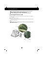
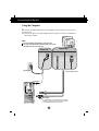
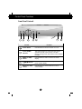
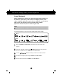
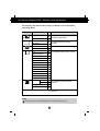
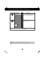
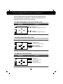
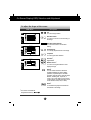
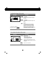
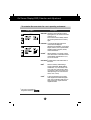
Important Precautions
This unit has been engineered and manufactured to ensure your personal
safety, however improper use may result in potential electrical shock or fire
hazards. In order to allow the proper operation of all safeguards
incorporated in this monitor, observe the following basic rules for its
installation, use, and servicing.
On Safety
Use only the power cord supplied with the unit. In case you use another power
cord, make sure that it is certified by the applicable national standards if not being
provided by the supplier. If the power cable is faulty in any way, please contact the
manufacturer or the nearest authorized repair service provider for a replacement.
The power supply cord is used as the main disconnection device. Ensure that the
socket-outlet is easily accessible after installation.
Operate the monitor only from a power source indicated in the specifications of
this manual or listed on the monitor. If you are not sure what type of power supply
you have in your home, consult with your dealer.
Overloaded AC outlets and extension cords are dangerous. So are frayed power
cords and broken plugs. They may result in a shock or fire hazard. Call your service
technician for replacement.
Do not Open the Monitor.
There are no user serviceable components inside.
There are Dangerous High Voltages inside, even when the power is OFF.
Contact your dealer if the monitor is not operating properly.
To Avoid Personal Injury :
Do not place the monitor on a sloping shelf unless properly secured.
Use only a stand recommended by the manufacturer.
Do not try to roll a stand with small casters across thresholds or deep pile
carpets.
To Prevent Fire or Hazards:
Always turn the monitor OFF if you leave the room for more than a short period
of time. Never leave the monitor ON when leaving the house.
Keep children from dropping or pushing objects into the monitor's cabinet
openings. Some internal parts carry hazardous voltages.
Do not add accessories that have not been designed for this monitor.
During a lightning storm or when the monitor is to be left unattended for an
extended period of time, unplug it from the wall outlet.
Do not bring magnetic devices such as magnets or motors near the picture
tube.
A1
Important Precautions
On Installation
Do not allow anything to rest upon or roll over the power cord, and do not place
the monitor where the power cord is subject to damage.
Do not use this monitor near water such as near a bathtub, washbowl, kitchen
sink, laundry tub, in a wet basement, or near a swimming pool.
Monitors are provided with ventilation openings in the cabinet to allow the release
of heat generated during operation. If these openings are blocked, built-up heat
can cause failures which may result in a fire hazard. Therefore, NEVER:
Block the bottom ventilation slots by placing the monitor on a bed, sofa, rug,
etc.
Place the monitor in a built-in enclosure unless proper ventilation is provided.
Cover the openings with cloth or other material.
Place the monitor near or over a radiator or heat source.
On Cleaning
Unplug the monitor before cleaning the face of the monitor screen.
Use a slightly damp (not wet) cloth. Do not use an aerosol directly on the
monitor screen because overspray may cause electrical shock.
On Repacking
Do not throw away the carton and packing materials. They make an ideal
container in which to transport the unit. When shipping the unit to another
location, repack it in its original material.
A2
Connecting the Monitor
Before setting up the monitor, ensure that the power is turned off to the
monitor, computer system, and other attached devices.
Carefully set the monitor face-down with the underside facing you.
Connecting the Tilt/Swivel stand
1. Align the hooks on the tilt/swivel stand with the matching slots in the base of
the monitor.
2. Insert the hooks into slots.
3. Slide the tilt/swivel stand toward the front of the monitor until the latches click
into the locked position.
NOTE
This illustration depicts the general model of connection. Your monitor may differ from the
items shown in the picture.
Slot
Hook
Latch
A3
Hook
Connecting the Monitor
Using the Computer
1. Connect the signal cable. When mated, tighten the thumbscrews to secure the
connection.
2. Connect the power cord into a properly power outlet that is easily accessible and
close to the monitor.
NOTE
This is a simplified representation of the rear view.
This rear view represents a general model; your monitor
may differ from the view as shown.
Signal Cable
Power Cord
Attached Type*
*
Detached Type*
* Varies according to model.
Wall-outlet type
*
PC-outlet type
PC
MAC
Mac adapter
For Apple Macintosh use, a separate plug adapter is needed to
change the 15 pin high density (3 row) D-sub VGA connector
on the supplied cable to a 15 pin 2 row connector.
A4
Control Panel Functions
Front Panel Controls
Control
Function
Power Button
Use this button to turn the monitor on or off.
Power (DPMS)
Indicator
This Indicator lights up green when the monitor
operates normally. If the monitor is in DPM
(Energy Saving) mode, this indicator color changes
to amber.
MENU (or OSD)
Button
Use this button to enter or exit the on screen
display.
Buttons
SELECT (or SET)
Button
Use these buttons to choose or adjust items in
the on screen display.
Use this button to enter a selection in the on
screen display.
A5
Control Panel Functions
Control
Direct Access Function
Button
Bring up Contrast adjustment
Button
Bring up Brightness adjustment
The Contrast and Brightness functions are also available
in the On Screen Display (OSD) menu.
SHARPNESS
Button
Brings up the clearness of the image :
letters, pictures or moving pictures.
For seeing letters
For seeing pictures or the photographs
For seeing moving pictures
AUTO adjustment function
When adjusting your display settings, always press the AUTO
button before entering the On Screen Display(OSD). This will
automatically adjust your display image to the ideal settings for
the current screen resolution size (display mode).
The best display mode is 1600 x 1200.
INPUT
Use this button to make Dsub or BNC connector active. This
feature is used when two computers are connected to the
display. The default setting is Dsub. The LED is turned on for
the D-sub connector and is turned off for the BNC connector.
A6
On Screen Display (OSD) Control Adjustment
Screen Adjustment
Making adjustments to the image size, position and operating parameters of
the monitor is quick and easy with the On Screen Display Control system.
A short example is quick and easy given below to familiarize you with the use
of the controls. The following section is an outline of the available
adjustments and selections you can make using the OSD.
NOTE
Allow the monitor to stabilize for at least 30 minutes before making image adjustments.
To make adjustments in the On Screen Display, follow these steps:
Case 1
Case 2
Press the MENU (or OSD) Button, then the main menu of the OSD
appears.
To access a control, use the
or
Buttons. When the icon you want
becomes highlighted, press the SELECT (or SET) Button.
Use the
Buttons to adjust the item to the desired level.
Accept the changes by pressing the SELECT (or SET) Button.
Exit the OSD by pressing the MENU (or OSD) Button.
A7
On Screen Display(OSD) Selection and Adjustment
The following table indicates all the On Screen Display control, adjustment,
and setting menus.
Main menu
Sub menu
Reference
To adjust the brightness and
contrast of the screen
Brightness
BRIGHTNESS/
CONTRAST
POSITION
SIZE
SHAPE
COLOR
Contrast
V Position
H Position
To adjust the position of the
screen
V Size
H Size
To adjust the size of the screen
Tilt
Side Pincushion
S Pincushion Balance
Parallelogram
Trapezoid
H Corner
Top Corner
Bottom Corner
Recall
Zoom
H Linearity
V Linearity
Recall
To adjust the shape of the screen
PRESET 6500K
9300K
Temp
R/G/B(User Color)
To customize the color of the
screen
: Adjustable
NOTE
The order of icons may differ depending on the model (A10~A14).
A8
On Screen Display(OSD) Selection and Adjustment
Main menu
SETUP
SPECIAL
Sub menu
Reference
Video Level
Language
OSD Time
OSD Position
Reset
Clamp
To customize the screen status
for a user's operating environment
Degauss
Natural Color
Auto Sizing
Sharpness
Moire H Moire
V Moire
Purity
Convergence
To improve the clarity and
stability of the screen
: Adjustable
NOTE
The order of icons may differ depending on the model (A10~A14).
A9
On Screen Display(OSD) Selection and Adjustment
You were introduced to the procedure of selecting and adjusting an item
using the OSD system. Listed below are the icons, icon names, and icon
descriptions of the all items shown on the Menu.
To adjust the brightness and contrast of the screen
OSD Adjust
Description
Brightness
To adjust the brightness of the screen.
Contrast
To adjust the contrast of the screen.
To adjust the position of the screen
OSD Adjust
Description
Vertical Position
To move image up and down.
Horizontal Position
To move image left and right.
To adjust the size of the screen
OSD Adjust
Description
Vertical Size
To adjust image height.
Horizontal Size
To adjust image width.
A10
On Screen Display(OSD) Selection and Adjustment
To adjust the shape of the screen
OSD Adjust
Description
Tilt
To correct image rotation.
Side Pincushion
To correct a concave or convex bowing of
the image.
Side Pincushion Balance
To correct the balance of both sides
bowing.
Parallelogram
To correctly adjust the skew of the image.
Trapezoid
To correct geometric distortion.
H Corner*
Top Corner*
Bottom Corner*
To correct an irregular distortion of the
displayed image.
Recall*
You can use this function to reload the
modified parameters for screen display
operation, as specified by the user after
purchase: Side Pincushion, Side Pincushion
Balance, Parallelogram, Trapezoid , H
Corner, Top Corner, Bottom Corner (These
recalled options may differ depending on the
mode selected: Preset, User, or New).
Zoom*
To simultaneously adjust horizontal and
vertical size of the image.
* This function is available for
designated models only.
A11
To adjust the shape of the screen
OSD Adjust
Description
H. Linearity*
To adjust the horizontal width of edge of
the image.
V. Linearity*
To adjust the vertical width of edge of the
image.
Recall*
You can use this function to reload the
modified parameters for screen display
operation, as specified by the user after
purchase: Zoom, H/V Linearity (These
recalled options may differ depending on the
mode selected: Preset, User, or New).
* This function is available for
designated models only.
To customize the color of the screen
OSD Adjust
Description
PRESET 6500K/ 9300K
Select the screen color.
• 6500K: Slightly reddish white.
• 9300K: Slightly bluish white.
TEMP
RED
GREEN
BLUE
A12
Select the screen temperature which you
prefer among reddish or bluish or any color
in between.
Set your own color levels.
On Screen Display(OSD) Selection and Adjustment
To customize the screen status for a user's operating environment
OSD Adjust
Description
VIDEO LEVEL This item is used to select the monitor's
input signal level. The normal level used for
most PCs is 0.7V.
If the screen becomes suddenly washedout or blurred, please select 1.0V and try
again.
LANGUAGE To choose the language in which the
control names are displayed.
OSD Menus are available in 11 languages:
English, German, French, Spanish, Italian,
Swedish, Finnish, Portuguese, Korean,
Chinese and Russian.
OSD TIME*
Set the OSD time, i.e. the length of time a
menu will remain on-screen before it shuts
off automatically. Adjust the time to 5, 10,
20, 30 or 60 seconds.
OSD POSITION*To adjust position of the OSD window on
the screen.
RESET*
Return to all factory default settings
except "LANGUAGE, BRIGHTNESS,
CONTRAST": Tilt, Color 9300K, Video
Level, OSD Time, OSD Position, Moire,
Convergence (These reset options may
differ depending on the mode selected:
Preset, User, or New).
CLAMP*
In case of input SOG (Sync On Green)
Video Signal, the back raster will appear
green. Then, to select the SOG (Sync On
Green) in the clamp, it goes back to the
original back raster.
* This function is available for
designated models only.
A13
On Screen Display(OSD) Selection and Adjustment
To improve the clarity and stability of the screen
OSD Adjust
DEGAUSS
NATURAL COLOR
AUTO SIZING
SHARPNESS
Description
ON
OFF
ON
DEGAUSS
To manually demagnetize the screen to
avoid showing incorrect images or colors.
NATURAL
COLOR*
This is have the real color of the image.
93.6 kHz / 75.0 Hz
AUTO SIZING* This will automatically adjust your display
image to the ideal settings for the current
screen resolution size (display mode).
MOIRE
PURITY
CONVERGENCE
SHARPNESS* This is to adjust the clearness of the
screen.
It is recommended to use this to see
movies or moving picture.
93.6 kHz / 75.0 Hz
MOIRE
This item allows you to reduce the degree
of moire. (Moire is caused by interference
Horizontal Scan Line with the periodical
dot screen). It is normally OFF(H:0/V:0).
The moire adjustments may affect the
focus of the screen.
Moire adjustments may shake slightly
while the moire reduction function is on.
PURITY*
Use to adjust the purity on the screen if
the color appears uneven.
CONVERGENCE*
This is to adjust the alignment of red
and blue fields.
* This function is available for
designated models only.
A14
Troubleshooting
Check the following before calling for service.
No image appears
Is the power cord of the
monitor connected?
Check and see if the power cord is connected properly to
the power outlet.
Is the power indicator light
on?
Press the Power button.
Is the power on and the
power indicator green?
Adjust the brightness and the contrast.
Is the power indicator
amber?
If the monitor is in power saving mode, try moving the
mouse or pressing any key on the keyboard to bring up
the screen.
Do you see an "OUT OF
FREQUENCY" message
on the screen?
This message appears when the signal from the PC
(video card) is out of horizontal or vertical frequency
range of the monitor. See the 'Specifications' section of
this manual and configure your monitor again.
Do you see a "SELF
DIAGNOSITICS" message
on the screen?
This message appears when the signal cable between
your PC and your monitor is not connected. Check the
signal cable and try again. In case of using the BNC
connector, this message also appears in the DPM
mode. Check the signal cable or press any key on the
keyboard to bring up the screen.
The screen is flickering.
Is the vertical frequency
less than 70Hz or is your
monitor set to the
interlaced mode?
Set the vertical frequency to 72Hz or higher, and
consult the video card user manual for instructions on
converting to a non-interlaced mode.
(You can set this option under the Display icon of the
Control Panel.)
Do you have any
magnetic material such
as adapter, or highvoltage line near to your
monitor?
Remove magnetic sources, such as power
adapters, speakers, or high-voltage lines, away from
the monitor.
Do you hear a "~ding"
sound while the monitor
is flickering?
Use the normal degaussing function. This function
clears the screen and reduces any screen blur that
may occur due to the surrounding magnetic field. The
screen may flicker for about 5 seconds, accompanied
by a "~ding" sound.
A15
Troubleshooting
The screen color is not normal.
Do you see basic
discoloration (16 colors)?
Is the screen color unstable
or monochrome?
Do you see two fine
horizontal lines on the
screen?
Do you see a partial
blurring on the screen?
Set the color depth to 256 colors or higher: use 'Control
Panel' 'Display' 'Settings' 'Color Palette'
Check the connection of the signal cable. Or pull out
the video card of the PC and insert it again.
Two fine horizontal lines may be visible on the
screen. This is not a fault or defect of the moitor and
is normal for all aperture grille type displays.
The fine lines are the shadows of Damper Wires
which are used to reduce the susceptibility of the
CRT’s aperture grille to shock or vibration.
This happens due to interference from surrounding
magnetic fields, as created when speakers, steel
structures, or high-voltage lines are placed near the
monitor. Remove any such materials from the
immediate vicinity and use the DEGAUSS icon on
the screen adjustment menu to fix the screen.
I see an after-image on the screen.
Do you see the after-image
even when you turn off
the monitor?
A premature aging of the monitor pixels may cause the
prolonged display of a single image on the screen. Be
sure to use a screen saver to maximize the service life of
the monitor.
I see waves on the screen.
Do you see the wave
directly on the screen?
This occurs in inverse proportion to the screen focus,
which can be caused by a particular frequency or video
card. Brighten the screen and use the 'MOIRE' icon on
the screen adjustment menu to adjust the screen.
Have you installed the monitor driver?
Have you installed the
monitor driver?
Be sure to install the monitor driver from the monitor
driver CD (or diskette) that comes with your monitor. Or,
you can also download the driver from our web site:
http://www.lge.com.
A16
Specifications
Picture Tube
Sync Input
Video Input
Plug&Play
Power
Consumption
Dimensions
&Weight
(with tilt/ swivel
stand)
Power Input
Environmental
Conditions
Tilt/Swivel Stand
Signal cable
Power cord
Regulations
22 inches (20 inches viewable), Natural Flat Tube
90 degree deflection
0.24mm Grille pitch
ARAS( Anti-Reflective Anti-Static) coating
Horizontal Freq. 30 - 124kHz (Automatic)
Vertical Freq.
50 - 160Hz (Automatic)
Input Form
Separate TTL, Positive/Negative
CompositeTTL, Positive/Negative
SOG(Sync On Green)
Signal Input
15 pin D-Sub / 5 BNC Connector
Input Form
Separate, RGB Analog, 0.7Vp-p/75 ohm, Positive
Resolution(max) 2048 x 1536@75Hz
DDC 1/2B
≤ 115W(130W)
Normal
Stand-by/Suspend ≤ 8W(20W)
Power Off
≤ 3W(18W)
*( ) : with USB
Width
50.3cm / 19.8 inches
Height
50.9 cm / 20.4 inches
Depth
47.7 cm / 18.8 inches
Net
31.3 kg (69.0 lbs)
AC 100-240V 50/60Hz 2.0A
Operating Conditions
Temperature
5˚C to 35 ˚C
Humidity
10 % to 90 % non-Condensing
Storage Conditions
Temperature
-20˚C to 60 ˚C
Humidity
5 % to 90 % non-Condensing
Attached( ), Detached ( O )
Attached( ), Detached ( O )
Attached or Detached
TCO99
NOTE
Information in this document is subject to change without notice.
A17
Specifications
Preset Modes (Resolution)
Display Modes (Resolution)
1
2
3
4
5
6
7
8
9
VESA
VESA
VESA
VESA
VESA
VESA
VESA
VESA
VESA
Horizontal Freq. (kHz)
Vertical Freq. (Hz)
31.47
53.68
60.02
68.68
79.98
91.15
93.75
106.25
121.95
60
85
75
85
75
85
75
85
75
640 x 480
800 x 600
1024 x 768
1024 x 768
1280 x 1024
1280 x 1024
1600 x 1200
1600 x 1200
2048 x 1536
A18
Using the BNC connector with other types of video cards
Using the BNC connectors with other types of video cards. Follow the
example that fits your needs.
1.
In case of using a composite sync on green video signal(Sync On Green):
Connect each R,G and B video signals to BNC receptacles on the back of the
monitor.
B
G
Green
Blue
2.
R
Red
In case of using an external composite sync signal:
Connect each R, G and B video signals and composite sync signal to the BNC
receptacles on the rear panel.
B
G
R
*
COMP.
HD
* Varies according to model.
Green
Gray
3.
Red
Blue
In case of using a separate horizontal and vertical sync signal:
Connect each R, G and B video signals and the horizontal and vertical sync
signal to BNC receptacles on rear panel.
B
*
COMP.
HD
G
R
VD
Green
* Varies according to model.
Gray
Black
Blue
Red
NOTE
This package does not include the BNC connectors but you can
purchase them at your local computer stores.
This monitor does not support the DDC function, if you use the
5 BNC connectors with other types of video cards.
A19
HD : Horizontal Drive
VD : Vertical Drive
COMP : Composite
Making use of USB (Universal Serial Bus)
USB (Universal Serial Bus) is an innovation in connecting your different
desktop peripherals conveniently to your computer. By using the USB, you will
be able to connect your mouse, keyboard, and other peripherals to your
monitor instead of having to connect them to your computer. This will give you
greater flexibility in setting up your system. USB allows you to connect a chain
of up to 120 devices on a single USB port; and you can “hot” plug (attach them
while the computer is running) or unplug them while maintaining the Plug and
the Plug auto detection and configuration. This monitor has an integrated BUSpowered USB hub, allowing up to 4 other USB devices to be attached it.
USB connection
1. Connect the upstream port of the monitor to the downstream port of the USB
compliant PC or another hub using the USB cable. (Computer must have a
USB port)
2.
Connect the USB compliant peripherals to the downstream ports of the
monitor.
This is a simplified representation
of the rear view.
This is a simplified representation
of the side view.
USB downstream Ports
connect the cables from USB
compliant peripherals-such as
keyboard, mouse, etc
To USB downstream port
of the USB compliant PC
or another hub cable
NOTE
To activate the USB hub function, the monitor must be connected to a USB compliant
PC(OS) or another hub with the USB cable(enclosed).
When connecting the USB cable, check that the shape of the connector at the cable side
matches the shape at the connecting side.
Even if the monitor is in a power saving mode, USB compliant devices will function when
they are connected the USB ports(both the upstream and downstream) of the monitor.
A20
Making use of USB (Universal Serial Bus)
USB Specifications
USB standard
Downstream power supply
Communication speed
USB port
Rev. 1.1 complied BUS-powered hub
500mA for each (MAX)
12 Mbps (full), 1.5 Mbps (low)
1 Upstream port / 4 Downstream ports
IMPORTANT: These USB connectors are not designed for use with high-power USB devices
such as a video camera, scanner, etc. LGE recommends connecting high-power USB devices
directly to the computer
A21