1
Intel® Server Board
SE7500CW2
Technical Product Specification
Intel Document Number C19122-002
Revision 1.50
June 2003
Enterprise Platforms and Services Marketing
Revision History
Date
Revision
Number
Modifications
5/29/2002
1.0
Initial release
6/06/2002
1.01
Minor technical and grammatical updates from review comments
9/9/2002
1.10
Updated BIOS menus, updated BIOS crisis recovery, added BIOS Beep
codes, and MTBF testing results.
12/2/2002
1.20
Added Section 9.3.3 on ICH3 power cycling.
1/24/2003
1.30
Re-added updates BIOS crisis recovery, Beep codes, MTBF, additionally
power-cycling issues, and Specification Update material as Appendix B.
2/10/2003
1.40
Updated power-cycling process.
6/20/2003
1.50
Updated Appendix B with monthly specification information.
Disclaimers
Information in this document is provided in connection with Intel® products. No license, express
or implied, by estoppel or otherwise, to any intellectual property rights is granted by this
document. Except as provided in Intel's Terms and Conditions of Sale for such products, Intel
assumes no liability whatsoever, and Intel disclaims any express or implied warranty, relating to
sale and/or use of Intel products including liability or warranties relating to fitness for a particular
purpose, merchantability, or infringement of any patent, copyright or other intellectual property
right. Intel products are not intended for use in medical, life saving, or life sustaining
applications. Intel may make changes to specifications and product descriptions at any time,
without notice.
Designers must not rely on the absence or characteristics of any features or instructions marked
"reserved" or "undefined." Intel reserves these for future definition and shall have no
The Server Board SE7500CW2 may contain design defects or errors known as errata which
may cause the product to deviate from published specifications. Current characterized errata
are available on request.
Intel, Pentium, Itanium, and Xeon are trademarks or registered trademarks of Intel Corporation.
*Other brands and names may be claimed as the property of others.
Copyright © Intel Corporation 2003.
Table of Contents
1.
Introduction ........................................................................................................................ 11
1.1
2.
Server Board SE7500CW2 Overview ................................................................................ 12
2.1
3.
Processor Support ................................................................................................... 14
3.1.2
Memory Subsystem ................................................................................................. 16
Intel E7500 Chipset ....................................................................................................... 19
3.2.1
MCH Memory Architecture Overview ....................................................................... 20
3.2.2
MCH North Bridge.................................................................................................... 21
3.2.3
P64H2 ...................................................................................................................... 21
3.2.4
ICH3-S ..................................................................................................................... 22
3.3
Super I/O ....................................................................................................................... 24
3.3.1
Serial Ports............................................................................................................... 24
3.3.2
BIOS Flash............................................................................................................... 25
Included PCI Devices ......................................................................................................... 26
4.1
ATA-100 RAID ............................................................................................................... 26
4.2
Video Controller ............................................................................................................. 27
4.3
Network Interface Controller (NIC) ................................................................................ 29
4.4
Optional SCSI Card ....................................................................................................... 30
4.5
Interrupt Routing ............................................................................................................ 30
4.5.1
Legacy Interrupt Routing.......................................................................................... 30
4.5.2
APIC Interrupt Routing ............................................................................................. 31
4.5.3
Serialized IRQ Support ............................................................................................ 32
4.5.4
IRQ Scan for PCIIRQ ............................................................................................... 32
Hardware Monitoring ......................................................................................................... 36
5.1
6.
Processor and Memory Subsystem ............................................................................... 14
3.1.1
3.2
5.
Feature Set .................................................................................................................... 12
Functional Architecture ..................................................................................................... 14
3.1
4.
Audience........................................................................................................................ 11
LANDesk* Client Manager............................................................................................. 38
System BIOS ....................................................................................................................... 39
6.1.1
6.2
System Flash ROM Layout ...................................................................................... 39
System Configuration and Initialization.......................................................................... 40
6.2.1
Memory .................................................................................................................... 40
6.2.2
Processors ............................................................................................................... 42
6.2.3
Extended System Configuration Data (ESCD), Plug and Play (PnP) ...................... 43
6.2.4
Legacy ISA Configuration ........................................................................................ 44
6.2.5
Automatic Detection of Video Adapters ................................................................... 44
6.2.6
Keyboard / Mouse Configuration.............................................................................. 44
6.2.7
Floppy Drives ........................................................................................................... 45
6.2.8
Universal Serial Bus (USB) ...................................................................................... 45
6.3
BIOS Supported Server Management Features ............................................................ 46
6.3.1
Advanced Configuration and Power Interface (ACPI).............................................. 46
6.3.2
Wake Events ............................................................................................................ 47
6.3.3
Wired For Management (WFM) ............................................................................... 49
6.3.4
Console Redirection................................................................................................. 50
6.3.5
Serial Ports............................................................................................................... 53
6.3.6
System Management BIOS (SMBIOS) .................................................................... 53
6.3.7
Windows Compatibility ............................................................................................. 54
6.4
BIOS Serviceability Features ......................................................................................... 55
6.4.1
6.5
BIOS and BIOS Setup ................................................................................................... 58
6.5.1
BIOS Setup Utility .................................................................................................... 58
6.5.2
Entering the BIOS Setup Utility ................................................................................ 59
6.5.3
Keyboard Command Bar.......................................................................................... 59
6.5.4
Menu Selection Bar.................................................................................................. 61
6.5.5
Main Menu ............................................................................................................... 62
6.5.6
Advanced Menu ....................................................................................................... 64
6.5.7
Security Menu .......................................................................................................... 74
6.5.8
Power Menu ............................................................................................................. 75
6.5.9
Boot Menu................................................................................................................ 76
6.5.10
System Menu.......................................................................................................... 77
6.5.11
Exit Menu................................................................................................................ 78
6.6
7.
Flash Update Utility .................................................................................................. 56
BIOS Security Features ................................................................................................. 79
6.6.1
Operating Model....................................................................................................... 79
6.6.2
Password Protection ................................................................................................ 79
Error Reporting and Handling ........................................................................................... 81
7.1
POST Codes, Error Messages, and Error Codes .......................................................... 81
7.1.1
Port 80 Codes .......................................................................................................... 81
7.1.2
BIOS POST Beep Codes ......................................................................................... 86
v
Revision 1.50
8.
7.1.3
BIOS Recovery Beep Codes.................................................................................... 88
7.1.4
POST Error Codes and Messages........................................................................... 88
7.1.5
Memory Error Codes................................................................................................ 91
Connectors and Jumper Blocks ....................................................................................... 92
8.1
Main Power Connector .................................................................................................. 92
8.2
Memory Module Connector ........................................................................................... 93
8.3
Processor Heat Syncs ................................................................................................... 94
8.4
Processor Socket........................................................................................................... 94
8.5
System Management Headers ...................................................................................... 96
I2C Header................................................................................................................ 96
8.5.1
9.
8.6
PCI Slot Connector ........................................................................................................ 97
8.7
Front Panel Connectors................................................................................................. 99
8.8
VGA Connector............................................................................................................ 100
8.9
NIC Connectors ........................................................................................................... 100
8.10
ATA Connectors ....................................................................................................... 101
8.11
USB Connector......................................................................................................... 102
8.12
Floppy Connector ..................................................................................................... 103
8.13
Serial Port Connectors ............................................................................................. 104
8.14
Keyboard and Mouse Connector.............................................................................. 105
8.15
Miscellaneous Headers and Jumpers ...................................................................... 106
8.15.1
Fan Headers......................................................................................................... 106
8.15.2
System Recovery and Update Jumpers ............................................................... 106
General Specifications..................................................................................................... 108
9.1
Absolute Maximum Ratings ......................................................................................... 108
9.2
Power Budget .............................................................................................................. 108
9.3
Mean Time Between Failures (MTBF) Test Results .................................................... 110
9.4
Power Supply Constraints ........................................................................................... 110
9.4.1
Server Chassis SC5200 Timing Requirements with the ICH3-S ........................... 110
9.4.2
BIOS <F2> “Stay off” Switch Limitations................................................................ 110
9.5
Power Supply Specifications ....................................................................................... 110
9.5.1
Power Timing ......................................................................................................... 111
9.5.2
Voltage Recovery Timing Specifications................................................................ 113
9.6
Shock and Vibe Test Results....................................................................................... 113
10. Product Regulatory Compliance..................................................................................... 114
10.1.1
Product Safety Compliance .................................................................................. 114
10.1.2
Product EMC Compliance .................................................................................... 114
10.1.3
Product Regulatory Compliance Markings ........................................................... 114
10.2
Electromagnetic Compatibility Notices ..................................................................... 115
10.2.1
Europe (CE Declaration of Conformity) ................................................................ 115
10.2.2
Australian Communications Authority (ACA) (C-Tick Declaration of Conformity) 115
10.2.3
Ministry of Economic Development (New Zealand) Declaration of Conformity .... 115
10.2.4
BSMI (Taiwan)...................................................................................................... 115
10.3
Replacing the Back-Up Battery ................................................................................ 116
11. Mechanical Spefications.................................................................................................. 117
11.1
Mechanical Specifications ........................................................................................ 117
Appendix A: SE7500CW2 Integration and Usage Tips ........................................................ 119
Appendix B: Errata ................................................................................................................. 120
Glossary................................................................................................................................... 129
Reference Documents ............................................................................................................ 132
vii
Revision 1.50
List of Tables
Table 1. Intel Server Board SE7500CW2 Processor Support Matrix.......................................... 14
Table 2. Memory Bank Labels .................................................................................................... 18
Table 3. Supported DDRs........................................................................................................... 20
Table 4. ATA-100 RAID Level..................................................................................................... 26
Table 5. Video Modes ................................................................................................................. 28
Table 6. Optional Intel® 53C1000B1 SCSI card pin-out(J1)...................................................... 30
Table 7. PCI Interrupt Routing/Sharing....................................................................................... 31
Table 8. Interrupt Definitions....................................................................................................... 31
Table 9. Monitored Componnets................................................................................................. 36
Table 10: Allowed Combinations of Floppy Drive and Floppy Media......................................... 45
Table 11: Supported Wake Events ............................................................................................. 47
Table 12: Non-ASCII Key Mappings ........................................................................................... 51
Table 13: ASCII Key Mappings................................................................................................... 52
Table 14: SMBIOS Header Structure.......................................................................................... 53
Table 15: Setup Utility Screen .................................................................................................... 59
Table 16: Keyboard Commands ................................................................................................. 60
Table 17: Menu Selection Bar..................................................................................................... 61
Table 18: Main Menu .................................................................................................................. 62
Table 19: Primary/Secondary, Master/Slave Submenu .............................................................. 63
Table 20: Advanced Menu ......................................................................................................... 64
Table 21: I/O Device Configuration Submenu ........................................................................... 66
Table 22: On Board Device Submenu ....................................................................................... 68
Table 23: PCI Configuration Submenu ...................................................................................... 69
Table 24. Option ROM Scan Submenu ..................................................................................... 70
Table 25: Server Menu Submenu .............................................................................................. 70
Table 26: Console Redirection Submenu .................................................................................. 71
Table 27: Event Logging Submenu............................................................................................ 72
Table 28: Hardware Monitor Submenu ...................................................................................... 73
Table 29: Security Menu ............................................................................................................ 74
Table 30: Power Menu............................................................................................................... 75
Table 31: Boot Menu.................................................................................................................. 76
Table 32: System Menu ............................................................................................................. 77
Table 33: Exit Menu ................................................................................................................... 78
Table 34: Security Features Operating Model ............................................................................ 79
Table 35: System ROM BIOS POST task point .......................................................................... 81
Table 36: Crisis Disk Boot Block BIOS POST Task Point .......................................................... 86
Table 37: POST Error Beep Codes ............................................................................................ 87
Table 38. BIOS Recovery Beep Codes ...................................................................................... 88
Table 39: Post Error Message .................................................................................................... 88
Table 40: Memory Error Codes................................................................................................... 91
Table 41. Power Connector (J26) ............................................................................................... 92
Table 42. Auxiliary Signal Connector (J24)................................................................................. 92
Table 43. Auxiliary CPU Power Connector (J20) ........................................................................ 92
Table 44. DIMM Connectors (J37, J38, J39, J40) ...................................................................... 93
Table 45: Processor Heat Sync data – replacement information................................................ 94
Table 46. Socket 604 Processor Socket..................................................................................... 94
Table 47. SCSI HDD Header (J25)............................................................................................. 96
Table 48. P32-A 5V 32-bit/33 MHz PCI Slot ............................................................................... 97
Table 49. P64-B/P64-C 3.3V 64-bit/ 100MHz/133MHz PCI-X Slot ............................................. 97
Table 50. Front Panel 34-Pin Header (J3) .................................................................................. 99
Table 51. VGA Connector (J42)................................................................................................ 100
Table 52. RJ-45 Connector (J47)............................................................................................. 100
Table 53. ATA-100 40-pin Connectors (J4, J5, J6, J7)............................................................. 101
Table 54. USB Connectors (J43) .............................................................................................. 102
Table 55. Optional USB Connection Header (J11) ................................................................... 102
Table 56. Legacy 34-pin Floppy Connector (J10)..................................................................... 103
Table 57. External DB9 Serial 1 Port (J44)............................................................................... 104
Table 58. 9-pin Header Serial 2 Port (J28) ............................................................................... 104
Table 59. Keyboard and Mouse PS/2 Connector (J46) ............................................................ 105
Table 60. Three-pin Fan Headers (J1, J2, J15, J16, J29, J30)................................................. 106
Table 61. Configuration Jumper Options .................................................................................. 107
Table 62. Absolute Maximum Ratings ...................................................................................... 108
Table 63. Power Budget ........................................................................................................... 109
Table 64. SE7500CW2 Static Power Supply Voltage Specification ......................................... 110
Table 65. SE7500CW2 Dynamic Power Supply Voltage Specification .................................... 111
Table 66. Voltage Timing Parameters ...................................................................................... 112
Table 67. Turn On / Off Timing ................................................................................................. 112
Table 68. Transient Load Requirements................................................................................... 113
ix
Revision 1.50
Table 69. Server Board Connector Specifications .................................................................... 118
Table 70. Errata Summary........................................................................................................ 120
List of Figures
Figure 1. Server Board Block Diagram ....................................................................................... 13
Figure 2. Memory Sub-system Block Diagram............................................................................ 16
Figure 3. Memory Bank Label Definition..................................................................................... 18
Figure 4. ATA-100 RAID Level ................................................................................................... 27
Figure 5. Interrupt Routing Diagram (ICH3-S Internal) ............................................................... 33
Figure 6. Interrupt Routing Diagram ........................................................................................... 34
Figure 7. PCI Interrupt Mapping Diagram ................................................................................... 35
Figure 8. Hardware Monitoring ................................................................................................... 37
Figure 9. Configuration Jumpers (J106) ................................................................................... 106
Figure 10. Output Voltage Timing ............................................................................................. 111
Figure 11. Turn on / off Timing.................................................................................................. 112
Figure 12. Mechanical Drawing ................................................................................................ 117
Intel® Server Board SE7500CW2 TPS
1.
Introduction
Introduction
The Server Board SE7500CW2 Technical Product Specification (TPS) provides a high level
technical description for the Intel® Server Board SE7500CW2. It details the architecture and
feature set for all functional sub-systems that make up the server board.
This document is divided into the following main categories:
Chapter 2: Server Board SE7500CW2 Overview
Chapter 3: Functional Architecture
Chapter 4: Included PCI Devices
Chapter 5: Hardware Monitoring
Chapter 6: System BIOS
Chapter 7: Error Handling and Reporting
Chapter 8: SE7500CW2 Connectors and Jumper Blocks
Chapter 9: General Specifications
Chapter 10: Product Regulatory Compliance
Chapter 11: Mechanical Specifications
1.1
Audience
This document for technical personnel who want a technical overview of the Server Board
SE7500CW2. Familiarity with the personal computer, Intel server architecture, Intel processor
architecture, memory technologies and the Peripheral Component Interconnect (PCI) local bus
architecture is assumed.
11
Revision 1.50
2.
Server Board SE7500CW2 Overview
The Server Board SE7500CW2 is a monolithic printed circuit board with features that were
designed to support the general-purpose server market. The architecture is based around the
Intel® E7500 chipset and is capable of supporting one or two Intel® Xeon™ processors with
512k L2 cache and up to 4GB1 of memory.
2.1
Feature Set
The Server Board SE7500CW2 supports the following feature set:
•
•
•
•
•
•
Dual Intel Xeon processors using the 603-pin INT mPGA package.
400 MHz Front Side Bus
Intel E7500 server chipset
- MCH memory controller
- P64H2 64-bit I/O hub
- ICH3-S I/O controller
- FWH Firmware Hub
Support for up to four DDR200 or DDR266 compliant ECC DDR DIMMs providing up to
4GB1 of memory support.
Three separate and independent PCI buses:
- Segment A: 32-bit, 33 MHz, 5 V (P32-A) with four embedded devices:
2D/3D graphics controller: ATI Rage* XL with 8 MB of SDRAM
Two Intel® 10/100 82550PM Fast Ethernet Controllers
ATA-100 RAID controller: Promise Technology* PDC20267
Two PCI slots capable of supporting full length PCI add-in cards
- Segment B: PCI-X 64-bit, 66MHz, 3.3 V, (P64-B) with the following configuration:
Two PCI slots capable of supporting full length PCI add-in cards
- Segment C: PCI-X 64-bit, 133 MHz, 3.3 V (P64-C) with the following device:
One PCI slot capable of supporting full length PCI add-in cards
LPC (Low Pin Count) bus segment with two embedded devices:
- Super I/O controller chip providing all PC-compatible I/O (floppy, serial, keyboard,
mouse) as well as integrated hardware monitoring.
-
•
•
•
•
Flash ROM device for system BIOS: Intel® 8Mbit N82802AC Flash ROM.
Three external Universal Serial Bus (USB) ports with an additional internal header
providing one optional USB ports for front panel support.
Two IDE connectors, supporting up to four ATA-100 compatible devices
Support for up to four system fans and two processor fans.
SSI-compliant connectors for SSI interface support: front panel and power connectors.
1 As of the writing of this document, testing with 2GB DIMM modules was not complete and therefore not yet
supported. 2GB DIMM support would allow for up to 8GB of main memory. For updates on support of 2GB DIMM
modules, see http://support.intel.com/support/motherboards/server/se7500cw2.
Intel® Server Board SE7500CW2 TPS
Server Board SE7500CW2 Overview
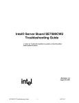
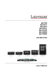
The figure below shows the functional blocks of the server board and the plug-in modules that it
supports.
4GB DDR200 or
DDR266 memory
Figure 1. Server Board Block Diagram
13
Revision 1.50
3.
Functional Architecture
This chapter provides a high-level description of the functionality distributed between the
architectural blocks of the Intel Server Board SE7500CW2.
3.1
Processor and Memory Subsystem
The Intel® E7500 Chipset provides a 36-bit address, 64-bit data processor host bus interface,
operating at 400MHz in the AGTL+ signaling environment. The MCH component of the chipset
provides an integrated memory controller, an 8-bit Hub Interface, and three 16-bit hub
interfaces.
The Hub Interface provides the interface to two 64-bit, 133/100/66/33-MHz, Rev 2.2 compliant
PCI-X bus via the P64H2. The Intel® Server Board SE7500CW2 directly supports up to 4GB1 of
ECC memory, using four DDR200 or DDR266 compliant ECC DIMMs. The ECC implementation
in the MCH can detect and correct single-bit errors, and it can detect multiple-bit errors, and
supports ‘Chip Kill’ feature with DIMMs using x4 technology not x8.
3.1.1
Processor Support
®
The Intel Server Board SE7500CW2 supports one or two Intel Xeon processors in the
Socket604 FCPGA2 package. When two processors are installed, all processors must be of
identical revision, core voltage, and bus/core speed. When only one processor is installed, it
should be in the socket labeled CPU1 and the other socket must be empty. The support circuitry
on the server board consists of the following:
•
•
Dual 604-pin processor sockets supporting 400 MHz FSB.
Processor host bus AGTL+ support circuitry.
Table 1. Intel Server Board SE7500CW2 Processor Support Matrix
Processor Family
Package Type
Frequency
Cache Size
Support
®
Intel Xeon™
FCPGA
1.8GHz
512KB
Yes
Intel Xeon
FCPGA
2.0GHz
512KB
Yes
Intel Xeon
FCPGA
2.2GHz
512KB
Yes
Intel Xeon
FCPGA
2.4GHz
512KB
Yes
Notes:
•
Processors must be populated in the sequential order. That is, processor socket #1
must be populated before processor socket #2.
•
The Server Board SE7500CW2 is designed to provide up to 65A per processors.
Processors with higher current requirements are not supported.
1 As of the writing of this document, testing with 2GB DIMM modules was not complete and therefore not yet
supported. 2GB DIMM support would allow for up to 8GB of main memory. For updates on support of 2GB DIMM
modules, see http://support.intel.com/support/motherboards/server/se7500cw2.
Intel® Server Board SE7500CW2 TPS
Functional Architecture
In addition to the circuitry described above, the processor subsystem contains the following:
•
•
•
•
Reset configuration logic.
Processor module presence detection logic.
APIC bus.
Server monitoring registers and sensors.
3.1.1.1
Processor VRD
The Server Board SE7500CW2 has a single VRD (Voltage Regulator Down) to support two
processors. It is compliant with the VRM 9.1 specification and provides a maximum of 130
AMPs, which is capable of supporting current supported processors as well as those supported
in the future.
The board hardware and PMC must read the processor VID (voltage identification) bits for each
processor before turning on the VRD. If the VIDs of the two processors are not identical, then
the PMC will not turn on the VRD and a beep code is generated.
3.1.1.2
Reset Configuration Logic
The BIOS determines the processor stepping, cache size, etc through the CPUID instruction.
The requirements are as follows:
•
All processors in the system must operate at the same frequency, have the same cache
sizes, and same VID. No mixing of product families is supported.
•
Processors run at a fixed speed and cannot be programmed to operate at a lower or
higher speed.
Note: The processor speed is the processor power on reset default value.
The processor information is read at every system power-on.
Note: No manual processor speed setting options exist either in the form of a BIOS setup option
or jumpers.
3.1.1.3
Processor Module Presence Detection
Logic is provided on the baseboard to detect the presence and identity of installed processors.
The PMC checks the logic and will not turn on the system DC power unless the VIDs of both the
processors mach in a DP configuration.
3.1.1.4
Interrupts and APIC
Interrupt generation and notification to the processors is done by the APICs in the ICH3 and the
P64H2 using messages on the front side bus.
15
Revision 1.50
3.1.2
Memory Subsystem
®
The Intel Server Board SE7500CW2 supports up to four DIMM slots for a maximum memory
capacity of 4GB1. The DIMM organization is x72, which includes eight ECC check bits. The
memory interface runs at 200MT/s. The memory controller supports memory scrubbing, singlebit error correction and multiple-bit error detection and chip kill support with DIMMS built on x4
technology. Memory can be implemented with either single sided (one row) or double-sided (two
row) DIMMs.
The figure below provides a block diagram of the memory sub-system implemented on the Intel®
Server Board SE7500CW2.
Figure 2. Memory Sub-system Block Diagram
1As of the writing of this document, testing with 2GB DIMM modules was not complete and therefore not yet
supported. 2GB DIMM support would allow for up to 8GB of main memory. For updates on support of 2GB DIMM
modules, see http://support.intel.com/support/motherboards/server/se7500cw2.
Intel® Server Board SE7500CW2 TPS
3.1.2.1
Functional Architecture
Memory DIMM Support
The Server Board SE7500CW2 supports DDR200 compliant registered ECC DIMMs and
DDR266 compliant ECC DIMMS operating at 200MT/s. Only DIMMs tested and qualified by
Intel or a designated memory test vendor are supported on the Server Board SE7500CW2. A
list of qualified DIMMs will be made available. Note that all DIMMs are supported by design, but
only fully qualified DIMMs will be supported.
The minimum supported DIMM size is 128 MB. Therefore, the minimum main memory
configuration is 2 x 128 MB or 256 MB. The largest size DIMM supported is a 2GB1 registered
DDR200 or DDR266 ECC DIMM based on 512-megabit technology.
•
•
•
•
Only registered DDR200 or DDR266 compliant, ECC, DDR memory 2will be
supported
ECC single-bit errors will be corrected and multiple-bit error will be detected.
The Server Board SE7500CW2 also supports Intel® x4 Single Device Data
Correction feature with x4 DIMMs.
The maximum memory capacity is 8 GB
The minimum memory capacity is 256MB
3.1.2.2
Memory Configuration
Memory interface between the MCH and DIMMs is 144 bit wide. This requires that two DIMMs
be populated per bank in order for the system to operate. At least one bank has to be populated
in order for the system to boot. If additional banks have less than two DIMMs, the memory for
that bank(s) will not be available to the system.
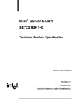
There are two banks of DIMMs, labeled 1 and 2. Bank 1 contains DIMM locations 1A and 1B
and bank 2 contains 2A and 2B. DIMM socket identifiers are marked with silkscreen next to
each DIMM socket on the baseboard. Note that the sockets associated with any given bank are
located next to each other.
The baseboard’s signal integrity and cooling are optimized when memory banks are populated
in order. Therefore, bank one must be populated before bank two.
DIMM and memory configurations must adhere to the following::
•
•
•
•
•
•
•
•
•
DDR200 or DDR266 ECC, registered, DDR DIMM modules
DIMM organization: x72 ECC
Pin count: 184
DIMM capacity: 128 MB, 256 MB, 512 MB, 1 GB, and 2 GB DIMMs
Serial PD: JEDEC Rev 2.0
Voltage options: 2.5V (VDD/VDDQ)
Interface: SSTL2
Two DIMMs must be populated in a bank for a 144-bit wide memory data path.
Any or all memory banks may be populated
1 As of the writing of this document, testing with 2GB DIMM modules was not complete and therefore not yet
supported. 2GB DIMM support would allow for up to 8GB of main memory. For updates on support of 2GB DIMM
modules, see http://support.intel.com/support/motherboards/server/se7500cw2.
17
Revision 1.50
Table 2. Memory Bank Labels
Memory DIMM
Bank
J39 (DIMM 1B), J40 (DIMM 1A)
1
J37 (DIMM 2B), J38 (DIMM 2A)
2
J38
J37
2B
2A
Bank 2
J40
J39
1B
1A
Bank 1
Figure 3. Memory Bank Label Definition
Intel® Server Board SE7500CW2 TPS
Functional Architecture
I2C Bus
3.1.2.3
The I2C bus is used by the system BIOS to retrieve DIMM information needed to program the
MCH memory registers which are required to boot the system.
3.1.2.4
DRAM ECC
The ECC used for DRAM provides Intel® x4 Single Device Data Correction technology
protection for x4 SDRAM modules. DRAM modules that are x8 use the same algorithm but will
not have Intel® x4 Single Device Data Correction technology protection, since at most only four
bits can be corrected with this ECC.
3.2
Intel E7500 Chipset
The Server Board SE7500CW2 is designed around the Intel E7500 chipset. The chipset
provides an integrated I/O bridge and memory controller, and a flexible I/O subsystem core
(PCI-X). This is targeted for multiprocessor systems and standard high-volume servers. The
Intel E7500 chipset consists of three components:
•
MCH: Memory Control Hub North Bridge. The MCH North Bridge accepts access
requests from the host (processor) bus and directs those accesses to memory or to one
of the PCI buses. The MCH monitors the host bus, examining addresses for each
request. Accesses may be directed to a memory request queue for subsequent
forwarding to the memory subsystem, or to an outbound request queue for subsequent
forwarding to one of the PCI buses. The MCH also accepts inbound requests from the
P64H2 and the ICH3-S. The MCH is responsible for generating the appropriate controls
to control data transfer to and from memory.
•
P64H2: PCI-X 64bit Hub 2.0 I/O Bridge. The P64H2 provides the interface for two 64bit, 133-MHz Rev. 2.2 compliant PCI-X buses (implemented on Intel® Server Board
SE7500CW2 as one bus with one 64-bit, 133MHz slot and one bus with two 64-bit,
100MHz slots). The P64H2 is both master and target on both PCI-X buses.
•
ICH3-S: IO Control Hub South Bridge. The ICH3-S controller has several components.
It provides the interface for a 32-bit, 33-MHz Rev. 2.2-compliant PCI bus. The ICH3-S
can be both a master and a target on that PCI bus. The ICH3-S also includes a USB
controller and an IDE controller. The ICH3-S is also responsible for much of the power
management functions, with ACPI control registers built in. The ICH3-S also provides a
number of GPIO pins and has the LPC bus to support low speed legacy I/O.
The MCH, P64H2, and ICH3-S chips provide the pathway between processor and I/O systems.
The MCH is responsible for accepting access requests from the host (processor) bus, and
directing all I/O accesses to one of the PCI buses or legacy I/O locations. If the cycle is directed
to one of the 64-bit PCI segments, the MCH communicates with the P64H2 through a private
interface called the HI (Hub Interface). If the cycle is directed to the ICH3-S, the cycle is output
on the MCH’s 8bit HI 1.5 bus. The P64H2 translates the HI 2.0 bus operation to a 64-bit PCI
Rev. 2.1-compliant signaling environment operating at from 133MHz to 33 MHz.
The HI 2.0 bus is 16 bits wide and operates at 66 MHz with 512MT/s, providing over 1 GB per
second of bandwidth.
19
Revision 1.50
All I/O for the Server Board SE7500CW2, including PCI and PC-compatible, is directed through
the MCH and then through either the P64H2 or the ICH3-S provided PCI buses.
•
•
The ICH3-S provides a 32-bit/33-MHz PCI bus hereafter called P32-A.
The P64H2 provides two independent 64-bit, 133-MHz PCI-X buses hereafter called
P64-B, and P64-C.
This independent bus structure allows all three PCI buses to operate independently.
3.2.1
MCH Memory Architecture Overview
The MCH supports a 144-bit Memory Sub-system that can support a maximum of 4GB1 (using
2GB DIMMs). This configuration needs external registers for buffering the memory address and
control signals. In this configuration MCH support four DDR200 compliant registered for
maximum of 8GB1. The four chip selects are registered inside MCH and need no external
registers for chip selects.
The memory interface runs at 200MT/s. The memory interface supports a 144-bit wide memory
array. It uses fifteen address lines (BA[1:0] and MA[12:0]) and supports 64Mb, 128Mb, 256Mb,
512Mb DRAM densities. The DDR DIMM interface supports memory scrubbing, single-bit error
correction, and multiple bit error detection and chip kill with x4 DIMMs.
3.2.1.1
DDR Configurations
The DDR interface supports up to 4GB1 of main memory and supports single- and doubledensity DIMMs. The DDR can be any industry-standard DDR. The following table shows the
DDR DIMM supported.
Table 3. Supported DDRs
DIMM
Capacity
128MB
DIMM
SDRAM
# SDRAM
# Address bits
SDRAM Density
Organization
Organization Devices/rows/Banks
rows/Banks/column
16M x 72
64Mbit
16M x 4
18/1/4
12/2/10
128MB
16M x 72
64Mbit
8M x 8
18/2/4
12/2/9
128MB
16M x 72
128Mbit
16M x 8
9/1/4
12/2/10
256MB
32M x 72
64Mbit
16M x 4
36/2/4
12/2/10
256MB
32M x 72
128Mbit
32M x 4
18/1/4
12/2/11
256MB
32M x 72
128Mbit
16M x 8
18/2/4
12/2/10
256MB
32M x 72
256Mbit
32M x 8
9/1/4
13/2/10
512MB
64M x 72
128Mbit
32M x 4
36/2/4
12/2/11
512MB
64M x 72
256Mbit
64M x 4
18/1/4
13/2/11
512MB
64M x 72
256Mbit
32M x 8
18/2/4
13/2/10
512MB
64M x 72
512Mbit
64M x 8
9/1/4
13/2/11
1GB
128M x 72
256Mbit
64M x 4
36/2/4
13/2/11
1GB
128M x 72
512Mbit
64M x 8
18/2/4
13/2/11
1As of the writing of this document, testing with 2GB DIMM modules was not complete and therefore not yet
supported. 2GB DIMM support would allow for up to 8GB of main memory. For updates on support of 2GB DIMM
modules, see http://support.intel.com/support/motherboards/server/se7500cw2.
Intel® Server Board SE7500CW2 TPS
Functional Architecture
1GB
128M x 72
512Mbit
128M x 4
18/1/4
13/2/12
2GB
256M x 72
512Mbit
64M x 8
TBD
TBD
2GB
256M x 72
512Mbit
128M x 4
TBD
TBD
2GB
256M x 72
512Mbit
128M x 4
TBD
TBD
3.2.2
MCH North Bridge
The Intel E7500 Chipset MCH North Bridge (MCH) is a 1005 ball FC-BGA device and uses the
proven components of previous generations like the Intel Xeon processor bus interface unit, the
Hub Interface unit, and the DDR memory interface unit. In addition, the MCH incorporates a Hub
Interface (HI). The HI interface enables the MCH to directly interface with the P64H2. The MCH
also increases the main memory interface bandwidth and maximum memory configuration with
a 144-bit wide memory interface.
The MCH integrates three main functions:
•
•
•
An integrated high performance main memory subsystem.
An HI 2.0 bus interface that provides a high-performance data flow path between the
host bus and the I/O subsystem.
A HI 1.5 bus which provides an interface to the ICH3-S (South Bridge).
Other features provided by the MCH include the following:
•
•
•
•
•
•
Full support of ECC on the processor bus.
Full support of Intel® x4 Single Device Data Correction on the memory interface with x4
DIMMs.
Twelve deep in-order queue.
Full support of registered DDR200 and DDR266 ECC DIMMs.
Support for 8GB1 of DDR DIMMs.
Memory scrubbing.
3.2.3
P64H2
The P64H2 is a 567 ball FC-BGA device and provides an integrated I/O bridge that provides a
high-performance data flow path between the HI 2.0 and the 64-bit I/O subsystem. This
subsystem supports peer 64-bit PCI-X segments. Because it has two PCI interfaces, the P64H2
can provide large and efficient I/O configurations. The P64H2 functions as the bridge between
the HI and the two 64-bit PCI-X I/O segments. The HI interface can support 1 GB/s of data
bandwidth.
1As of the writing of this document, testing with 2GB DIMM modules was not complete and therefore not yet
supported. 2GB DIMM support would allow for up to 8GB of main memory. For updates on support of 2GB DIMM
modules, see http://support.intel.com/support/motherboards/server/se7500cw2.
21
Revision 1.50
3.2.3.1
PCI Bus P64-B I/O Subsystem
P64-B supports the following embedded devices and connectors:
•
Two 184-pin, 3.3-volt keyed, 64-bit PCI expansion slot connectors running at 100MHz.
Both slots support 184-pin, 3.3V keyed, 64-bit PCI-X expansion slots. Both slots support
full-length PCI add-in cards.
The BIOS is responsible for setting the bus speed of P64-B. The bus speed will always be set
up to run at the speed of the slowest card installed.
3.2.3.2
PCI Bus P64-C I/O Subsystem
P64-C supports the following embedded devices and connectors:
•
One 184-pin, 3.3-volt keyed, 64-bit PCI expansion slot connector running at 133MHz.
This slot is capable of supporting a full length add-in PCI card.
• This expansion slot can be used for riser card, should this board be integrated into a
high-density chassis. The slot is designed to support up to 3 PCI slots on the riser,
however actual number of slots and slot speeds will be determined by the signal integrity
of the riser card used.
The BIOS is responsible for setting the bus speed of P64-C. The bus speed will always be set
up to run at the speed of the slowest card installed.
3.2.4
ICH3-S
The ICH3-S is a multi-function device, housed in a 421-pin BGA device, providing a HI 1.5 to
PCI bridge, a PCI IDE interface, a PCI USB controller, and a power management controller.
Each function within the ICH3-S has its own set of configuration registers. Once configured,
each appears to the system as a distinct hardware controller sharing the same PCI bus
interface.
On the Server Board SE7500CW2, the primary role of the ICH3-S is to provide the gateway to
all PC-compatible I/O devices and features. The Server Board SE7500CW2 uses the following
ICH3-S features:
•
•
•
•
•
•
•
•
•
32-bit PCI bus interface
16-bit LPC bus interface
IDE interface, with Ultra DMA 100 capability
Universal Serial Bus (USB) interface
PC-compatible timer/counter and DMA controllers
APIC and 8259 interrupt controller
Power management
System RTC
General purpose I/O
The following are the descriptions of how each supported feature is used on Server Board
SE7500CW2.
Intel® Server Board SE7500CW2 TPS
3.2.4.1
Functional Architecture
PCI Bus P32-A I/O Subsystem
The ICH3-S provides a legacy 32-bit PCI subsystem and acts as the central resource on this
PCI interface.
P32-A supports the following embedded devices and connectors:
•
•
•
•
An ATI* Rage* XL video controller with 3D/2D graphics accelerator
Promise Technology* PDC20267 dual channel ATA-100 RAID controller.
Two Intel 82550PM network controllers
Two 5V keyed expansion slots capable of supporting full length PCI add-in cards
operating at 33MHz
3.2.4.2
PCI Bus Master IDE Interface
The ICH3-S acts as a PCI-based Ultra DMA/100 IDE controller that supports programmed I/O
transfers and bus master IDE transfers. The ICH3-S supports two IDE channels, supporting two
drives each (drives 0 and 1). The Server Board SE7500CW2 provides two SSI compliant 40-pin
(2x20) IDE connectors to access the IDE functionality.
The Server Board SE7500CW2 IDE interface supports Ultra DMA/100 Synchronous DMA Mode
transfers on each 40-pin connector.
3.2.4.3
USB Interface
The ICH3-S contains three USB revision 1.1 controllers and four USB hubs. The USB controller
moves data between main memory and the six USB connectors. All six ports function identically
and with the same bandwidth. The Server Board SE7500CW2 implements 4 of the 6 ports on
the board.
The Server Board SE7500CW2 provides three external USB ports at the rear of the server
board. The triple stack USB connector is located within the standard ATX I/O panel area next to
the keyboard and mouse housing. The USB specification defines the external connectors.
The fourth USB ports is optional and can be accessed by cabling from the internal 9-pin
connector located on the baseboard to external USB ports located either in front or the rear of a
given chassis.
3.2.4.4
Compatibility Interrupt Control
The ICH3-S provides the functionality of two 82C59 PIC devices for ISA-compatible interrupt
handling.
3.2.4.5
APIC
The ICH3-S integrates an APIC that is used to distribute 24 interrupts.
23
Revision 1.50
3.2.4.6
Power Management
One of the embedded functions of the ICH3-S is a power management controller. The Server
Board SE7500CW2 uses this to implement ACPI-compliant power management features. The
Server Board SE7500CW2 supports sleep states S0, S4, and S5.
3.3
Super I/O
The Windbond* 83627HF Super I/O device contains all of the necessary circuitry to control two
serial ports, one parallel port, floppy disk, PS/2-compatible keyboard and mouse, and hardware
monitor controller. The Server Board SE7500CW2 supports the following features:
•
•
•
•
•
•
3.3.1
GPIOs
Two serial ports
Floppy
Keyboard and mouse
Local hardware monitoring
“Wake-on” control
Serial Ports
The Server Board SE7500CW2 provides two serial ports, an external serial port, and an internal
serial header. The following sections provide details on the use of the serial ports.
3.3.1.1
Serial 1
Serial 1 is a standard DB9 interface located at the rear I/O panel of the server board, to the left
of the video connector below the parallel port connector. Serial port 1 is designated by
silkscreen “Serial 1” and reference designator J44.
3.3.1.2
Serial 2
Serial 2 is an optional port, accessed through a 9-pin internal header (J28). A standard DH-10
to DB9 cable can be used to direct serial 2 to an external connector on any given chassis. The
serial 2 interface follow the standard RS232 pin out. The baseboard has a “Serial 2” silkscreen
label next to the connector. The serial number 2 connector is located just below PCI slot 5.
3.3.1.3
Floppy Disk Controller
The floppy disk controller (FDC) in the SIO is functionally compatible with floppy disk controllers
in the DP8473 and N844077. All FDC functions are integrated into the SIO including analog
data separator and 16-byte FIFO. The Server Board SE7500CW2 provides a standard 36-pin
interfaces for the floppy disk controller.
3.3.1.4
Keyboard and Mouse
Two external PS/2 ports, located on the back of the baseboard, are provided to access the
keyboard or mouse functions. The two ports are interchangeable and will automatically detect
and configure a keyboard or mouse plugged into either port.
Intel® Server Board SE7500CW2 TPS
3.3.1.5
Functional Architecture
Wake-on Control
The Super I/O contains functionality that allows various events to control the power-on and
power-off the system.
3.3.2
BIOS Flash
The Server Board SE7500CW2 incorporates an Intel® N82802AC (FWH8) Flash memory
component. The N82802AC is a high-performance 8-megabit memory component that provides
1024K x 8 of BIOS and non-volatile storage space. The flash device is connected through the
LPC Bus from the ICH3-S from the SIO.
25
Revision 1.50
4.
Included PCI Devices
4.1
ATA-100 RAID
The Intel® Server Board SE7500CW2 provides an embedded dual channel ATA-100 bus
through the use of the Promise* Technology PDC20267 ASIC. The PDC20267 ATA-100
controller contains two independent ATA-100 channels that share a single 32-bit, 33-MHz PCI
bus master interface as a multifunction device, packaged in a 128-pin PQFP.
The ATA-100 controller supports the following features:
•
•
•
•
•
The scatter / gather mechanism supports both DMA and PIO IDE drives and ATAPI
devices
Support for ATA and ATAPI proposal PIO Mode 0, 1, 2, 3, 4, DMA Mode 0, 1, 2, and
Ultra DMA Mode 0, 1, 2, 3, 4, 5
The IDE drive transfer rate is capable of up to 100 MB/sec per channel
The host interface complies with PCI Local Bus Specification, Revision 2.2
32-bit, 33-MHz bus speed and 132 MB/sec sustained transfer rate
The Promise PDC20267 supports IDE RAID through dual ATA-100 Channels. In a RAID
configuration, multiple IDE hard drives are placed into one or more arrays of disks. Each array is
seen as an independent disk, though the array may include upwards of two, three, or four
drives. The IDE RAID can be configured as followings:
Table 4. ATA-100 RAID Level
RAID Level
RAID 0 (Striping)
RAID 1 (Mirroring)
RAID 0+1 (Stripe/Mirror)
JBOD (Spanning)
Performance
Highest
Normal
High
Normal
Capacity
# Drives x Smallest Size
50% min
50% min
100% of all drives
# of Drives
2 to 4
2
4
2 to 4
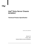
Intel® Server Board SE7500CW2 TPS
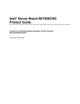
Included PCI Devices
Figure 4. ATA-100 RAID Level
RAID 0 configurations are used for high performance applications, as it doubles the sustained
transfer rate of its drives. RAID 1 configurations primarily used for data protection. It creates an
identical drive backup to a secondary drive. Whenever a disk write is performed, the controller
sends data simultaneously to a second drive located on a different data channel. With four
drives attached to dual ATA-100 channels, two striped drive pairs can mirror each other (RAID
0+1) for storage capacity and data redundancy.
4.2
Video Controller
The Intel® Server Board SE7500CW2 provides an ATI Rage XL PCI graphics accelerator, along
with 8 MB of video SDRAM and support circuitry for an embedded SVGA video subsystem. The
ATI Rage XL chip contains a SVGA video controller, clock generator, 2D and 3D engine, and
RAMDAC in a 272-pin PBGA. One 2Mx32 SDRAM chip provides 8 MB of video memory.
27
Revision 1.50
The SVGA subsystem supports a variety of modes, up to 1600 x 1200 resolution in 8/16/24/32
bpp modes under 2D, and up to 1024 x 768 resolution in 8/16/24/32 bpp modes under 3D. It
also supports both CRT and LCD monitors up to 100 Hz vertical refresh rate.
The Intel® Server Board SE7500CW2 provides a standard 15-pin VGA connector and supports
disabling of the on-board video through the BIOS setup menu or when a plug in video card is
installed in any of the PCI slots.
4.2.1.1
Video Modes
The ATI Rage XL chip supports all standard IBM VGA modes. The following table shows the
2D/3D modes supported for both CRT and LCD. The table specifies the minimum memory
requirement for various display resolution, refresh rates and color depths.
Table 5. Video Modes
2D Mode
Refresh Rate (Hz)
2D Video Mode Support
8 bpp
16 bpp
24 bpp
32 bpp
Supported
640x480
60, 72, 75, 90, 100
Supported
Supported
Supported
800x600
60, 70, 75, 90, 100
Supported
Supported
Supported
Supported
1024x768
60, 72, 75, 90, 100
Supported
Supported
Supported
Supported
1280x1024
43, 60
Supported
Supported
Supported
Supported
1280x1024
70, 72
Supported
–
Supported
Supported
1600x1200
60, 66
Supported
Supported
Supported
Supported
1600x1200
76, 85
Supported
Supported
Supported
–
3D Mode
Refresh Rate (Hz)
640x480
60,72,75,90,100
Supported
3D Video Mode Support with Z Buffer Enabled
Supported
Supported
Supported
800x600
60,70,75,90,100
Supported
Supported
Supported
Supported
1024x768
60,72,75,90,100
Supported
Supported
Supported
Supported
1280x1024
43,60,70,72
Supported
Supported
–
–
1600x1200
60,66,76,85
Supported
–
–
–
3D Mode
Refresh Rate (Hz)
640x480
60,72,75,90,100
Supported
3D Video Mode Support with Z Buffer Disabled
Supported
Supported
Supported
800x600
60,70,75,90,100
Supported
Supported
Supported
Supported
1024x768
60,72,75,90,100
Supported
Supported
Supported
Supported
1280x1024
43,60,70,72
Supported
Supported
Supported
–
1600x1200
60,66,76,85
Supported
Supported
–
–
Intel® Server Board SE7500CW2 TPS
4.2.1.2
Included PCI Devices
Video Memory Interface
The memory controller subsystem of the ATI Rage XL arbitrates requests from direct memory
interface, the VGA graphics controller, the drawing coprocessor, the display controller, the video
scalar, and hardware cursor. Requests are serviced in a manner that ensures display integrity
and maximum CPU/coprocessor drawing performance.
The server board supports an 8MB (512Kx32bitx4 Banks) SDRAM device for video memory.
4.3
Network Interface Controller (NIC)
The Server Board SE7500CW2 supports two 10Base-T/100Base-TX Network Interface
Controllers (NICs) based on the Intel 82550PM NIC. The 82550PM is a highly integrated PCI
LAN controller in a thin BGA 15mm package. The controller’s baseline functionality is equivalent
to that of the Intel 82559, with the addition of Alert-on-LAN functionality. The Server Board
SE7500CW2 supports independent disabling of the two NIC controllers using the BIOS Setup
menu.
The 82550PM supports the following features:
•
•
•
•
•
•
•
Glueless 32-bit PCI, CardBus master interface (Direct Drive of Bus), compatible with PCI
local Bus Specification, Revision 2.2.
Integrated IEEE 802.3 10Base-T and 100Base-TX compatible PHY.
IEEE 820.3u auto-negotiation support.
Full duplex support at both 10 Mbps and 100 Mbps operation.
Integrated UNDI ROM support.
MDI/MDI-X and HWI support.
Low power +3.3 V device.
4.3.1.1
NIC Connector and Status LEDs
The 82550PM drive two LEDs located on each network interface connector. The amber LED
indicates network connection when on, and transmit/receive activity when blinking. The yellow
LED indicates 100-Mbps operating mode when lit, and 10-Mbps when off.
29
Revision 1.50
4.4
Optional SCSI Card
Certain versions of the Server Board SE7500CW2 include an add-in Ultra-160 SCSI card. This
card has the following specifications:
•
•
•
•
•
•
•
•
Ultra 160 single channel based on the LSI 53C1000 SCSI controller
PCI 2.2 compliant
PCI 64-bit/66MHz operation
Universal PCI card edge connector
Low profile form factor, shipping with full-size PCI bracket attached and low profile
bracket in packaging
Internal and external connectors (internal standard 68-pin, external VHDI interface)
Termination: universal (LVD/SE) termination, automatic cable detection, software disable
4 pin header for off board LEDs
Pin-out for the card is as follows:
Table 6. Optional Intel® 53C1000B1 SCSI card pin-out(J1)
Pin
4.5
Signal Name
1
+5V
2
LED1_L
3
LED1_L
4
+5V
Interrupt Routing
The Server Board SE7500CW2 interrupt architecture accommodates both PC-compatible PIC
mode and APIC mode interrupts through use of the integrated I/O APICs in the ICH3-S.
4.5.1
Legacy Interrupt Routing
For PC-compatible mode, the ICH3-S provides two 82C59-compatible interrupt controllers. The
two controllers are cascaded with interrupt levels 8-15 entering on level 2 of the primary
interrupt controller (standard PC configuration). A single interrupt signal is presented to the
processors, to which only one processor will respond for servicing. The ICH3-S contains
configuration registers that define which interrupt source logically maps to I/O APIC INTx pins.
Interrupts, both PCI and IRQ types, are handled by the ICH3-S. The ICH3-S then translates
these to the APIC bus. The numbers in the table below indicate the ICH3-S PCI interrupt input
pin to which the associated device interrupt (INTA, INTB, INTC, INTD) is connected. The ICH3S’ I/O APIC exists on the I/O APIC bus with the processors.
Intel® Server Board SE7500CW2 TPS
Included PCI Devices
Table 7. PCI Interrupt Routing/Sharing
Interrupt
ATI Rage SL
Promise ATA-100 Controller
82550PM #2
82550PM #1
P64H2 BT INTR#
P64-C Slot 1
P64-B Slot 2
P64-B Slot 3
P32-A Slot 4
P32-A Slot 5
4.5.2
INT A
INT B
ICH3_PIRQF_L
ICH3_PIRQG_L
ICH3_PIRQE_L
ICH3_PIRQH_L
ICH3_PIRQC# (for PIC mode)
P1_IRQ0_L
P1_IRQ1_L
P2_IRQ0_L
P2_IRQ1_L
P2_IRQ4_L
P2_IRQ5_L
ICH3_PIRQB_L
ICH3_PIRQC_L
ICH3_PIRQD_L
ICH3_PIRQA_L
INT C
INT D
P1_IRQ2_L
P2_IRQ2_L
P2_IRQ6_L
ICH3_PIRQB_L
ICH3_PIRQD_L
P1_IRQ3_L
P2_IRQ3_L
P2_IRQ7_L
ICH3_PIRQC_L
ICH3_PIRQA_L
APIC Interrupt Routing
For APIC mode, the Server Board SE7500CW2 interrupt architecture incorporates three Intel
I/O APIC devices to manage and broadcast interrupts to local APICs in each processor. The
Intel I/O APICs monitor each interrupt on each PCI device including PCI slots in addition to the
ISA compatibility interrupts IRQ(0-15). When an interrupt occurs, a message corresponding to
the interrupt is sent across a three-wire serial interface to the local APICs. The APIC bus
minimizes interrupt latency time for compatibility interrupt sources. The I/O APICs can also
supply greater than 16 interrupt levels to the processor(s). This APIC bus consists of an APIC
clock and two bi-directional data lines.
4.5.2.1
Legacy Interrupt Sources
The table below recommends the logical interrupt mapping of interrupt sources on the Server
Board SE7500CW2. The actual interrupt map is defined using configuration registers in the
ICH3-S.
Table 8. Interrupt Definitions
ISA Interrupt
INTR
NMI
IRQ0
IRQ1
IRQ2
IRQ3
IRQ4
IRQ5
IRQ6
IRQ7
IRQ8_L
IRQ9
IRQ10
IRQ11
IRQ12
IRQ13
IRQ14
IRQ15
SMI*
Description
Processor interrupt.
NMI to processor.
System timer
Keyboard interrupt.
Slave PIC
Serial port 1 or 2 interrupt from SIO device, user-configurable.
Serial port 1 or 2 interrupt from SIO device, user-configurable.
Parallel Port / Generic
Floppy disk.
Parallel Port / Generic
Active low RTC interrupt.
SCI*
Generic
Generic
Mouse interrupt.
Floaty processor.
Compatibility IDE interrupt from primary channel IDE devices 0 and 1.
Secondary IDE Cable
System Management Interrupt. General purpose indicator sourced by the ICH3-S to the processors.
31
Revision 1.50
4.5.3
Serialized IRQ Support
The Intel® Server Board SE7500CW2 supports a serialized interrupt delivery mechanism.
Serialized Interrupt Requests (SERIRQ) consists of a start frame, a minimum of 17 IRQ / data
channels, and a stop frame. Any slave device in the quiet mode may initiate the start frame.
While in the continuous mode, the start frame is initiated by the host controller.
4.5.4
IRQ Scan for PCIIRQ
The IRQ / data frame structure includes the ability to handle up to 32 sampling channels with
the standard implementation using the minimum 17 sampling channels. The Server Board
SE7500CW2 has an external PCI interrupt serializer for PCIIRQ scan mechanism of ICH3-S to
support 16 PCI IRQs.
Intel® Server Board SE7500CW2 TPS
Included PCI Devices
ICH3-S IOAPIC 0
HI1.5 INTERFACE
IRQ0
IRQ1
IRQ2
IRQ3
IRQ4
IRQ5
IRQ6
IRQ7
IRQ8
IRQ9
IRQ10
IRQ11
IRQ12
IRQ13
IRQ14
IRQ15
IRQ16
IRQ17
IRQ18
IRQ19
IRQ20
IRQ21
IRQ22
IRQ23
IRQ0
IRQ1
IRQ2
IRQ3
IRQ4
IRQ5
IRQ6
IRQ7
IRQ8
IRQ9
IRQ10
IRQ11
IRQ12
IRQ13
IRQ14
IRQ15
IRQ16
IRQ17
IRQ18
IRQ19
IRQ20
IRQ21
IRQ22
IRQ23
ICH3-S
ICH3-S
8259PIC
HI2.0 INTERFACE
P64H2
IOAPIC 1
INTR
CPU1
NB
IRQ0
IRQ1
IRQ2
IRQ3
IRQ4
IRQ5
IRQ6
IRQ7
IRQ8
IRQ9
IRQ10
IRQ11
IRQ12
IRQ13
IRQ14
IRQ15
IRQ16
IRQ17
IRQ18
IRQ19
IRQ20
IRQ21
IRQ22
IRQ23
Hub-Link B
INTR
HI2.0 INTERFACE
CPU2
P64H2
IOAPIC 2
Figure 5. SE7500CW2 Interrupt Routing Diagram (ICH3-S Internal)
33
Revision 1.50
Super I/O
Timer
Keyboard
Cascade
Serial Port2/ISA
ISA
Floppy/ISA
ISA
RTC
SCI/ISA
ISA
ISA
SERIRQ
SERIRQ H
ICH3-S Interrupt Routing
Serialized IRQ Interface
Serial Port1/ISA
Mouse/ISA
Coprocessor Error
P IDE/ISA
Not Used
P64H2-A
PIRQA#
SLOT-4 -A/C#
PIRQB#
SLOT-4 -B/D#
PIRQC#
SLOT-5 -A/C#
PIRQD#
SLOT-5 -B/D#
PIRQE#
VGA
PIRQF#
ATA
PIRQG#
NIC1, NIC2
PIRQH#
Figure 6. Interrupt Routing Diagram
Intel® Server Board SE7500CW2 TPS
SLOT #5
SLOT #4
Included PCI Devices
SLOT #2
SLOT #3
SLOT #1
INT A
P2-IRQ4
P2-IRQ0
P1-IRQ0
INT B
P2-IRQ5
P2-IRQ1
P1-IRQ1
INT C
P2-IRQ6
P2-IRQ2
P1-IRQ2
INT D
P2-IRQ7
P2-IRQ3
P1-IRQ3
PCI
RISER
P1-IRQ4
P1-IRQ6
ICH3
PIRQH#
ICH3
PIRQG#
ICH3
PIRQF#
NIC1
ATA
VGA
ICH3
PIRQA#
ICH3
PIRQD#
ICH3
PIRQC#
ICH3
PIRQB#
P64H2
BT_INTR#
ICH3
PIRQE#
NIC2
Note: P1 is P64H2 PCI-bus A, P2 is P64H2 PCI-bus B
Figure 7. PCI Interrupt Mapping Diagram
35
Revision 1.50
5.
Hardware Monitoring
The Server Board SE7500CW2 has an integrated Winbond* 83627HF SIO controller with
integrated hardware monitoring and a MAX6651 controller both of which provide basic hardware
monitoring capabilities. These controllers use the I2C bus to communicate to all the sensors
integrated on the baseboard.
Below is a table of monitored headers and sensors on the Server Board SE7500CW2.
Table 9. Monitored Componnets
Voltage
Fan Speed
Temperature
Item
Description
Vcpu
Monitors processor voltage. (sIO)
1.8V
Monitors +1.8V. (sIO)
3.3V
Monitors +3.3V. (sIO)
5V
Monitors 5VSB (Internal). (sIO)
AUX3V
Monitors +12Vin. (sIO)
ENG12V
Monitors –12Vin (should be same as 12V @ Power-Supply). (sIO)
2.5V
Monitors -5V. (sIO)
Vbat
Monitors battery voltage (sIO)
AUX5V
Monitors 5VSB. (sIO)
PWM1
Controls 2 front system fans (sIO)
PWM2
Controls 2 rear system fans (sIO)
PWM3
Controls 2 CPU fans (MAX6651)
FanIO1
Monitors front fan (sIO)
FanIO2
Monitors front fan (sIO)
TACH0
Monitors rear fan (MAX6651)
TACH1
Monitors rear fan (MAX6651)
TACH2
Monitors CPU fan (MAX6651)
TACH3
Monitors CPU fan (MAX6651)
CPU1
Monitors primary processor temperature. (sIO)
CPU2
Monitors secondary processor temperature. (sIO)
Ambient Temperature
Monitors Ambient temperature (sIO)
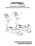
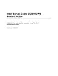
Below is a diagram explaining what the Winbond* W83627HF chip and MAX6651 chip monitor
on the Intel® Server Board SE7500CW2 and how the monitoring is accomplished.
Intel® Server Board SE7500CW2 TPS
Ambient Temperature
Hardware Monitoring
VTIN1
CPU1 (604 pins)
VTIN2 Temperature Sensor 2 High Byte (Index 50h, Bank 1)
CPU2 (604 pins)
VTIN3 Temperature Sensor 3 High Byte (Index 50h, Bank 2)
Vcpu
VCOREA (Index 20h)
+1.8V
VCOREB (Index 21h)
+3.3V
V3.3 (Index 22h)
+5V
AVCC
AUX3V
+12VIN (Index 24h)
ENG12V
-12VIN (Index 25h)
+2.5V
-5VIN (Index 26h)
Battery
Vbat
AUX5V
5VSB
2 front system fans (J2, J1)
PWM1
2 rear system fans (J30, J29)
PWM2
front fan (J2)
FanIO1
front fan (J1)
FanIO2
2 CPU fans (J15, J16)
PWM3
rear fan (J30)
TACH0
rear fan (J29)
TACH1
CPU fan (J15)
TACH2
CPU fan (J16)
TACH3
W83627HF
ICH3-S
MAX6651
Figure 8. Hardware Monitoring
37
Revision 1.50
5.1
LANDesk* Client Manager
Included with the Server Board SE7500CW2 is a copy of the LANDesk Client Manager (LDCM)
software. This software utilizes the management controllers on the server board to display realtime status of the sensors on the baseboard and provide alerts if sensors go outside their predetermined thresholds. The software runs on the Microsoft* Windows* 2000 operating system
and provides a graphical user interface (GUI) for monitoring the health of the server system.
The initial version of the software that shipped on the first boards was only capable of
monitoring critical sensors on the board. Updated versions of the software files to allow for
additional monitoring capability will be posted to the Server Board SE7500CW2 support website
at http://support.intel.com/support/motherboards/server/se7500cw2. Please check this web site
for updates to the software prior to installing and using it. Additionally, documentation on how to
install and use the LDCM software is provided on the Server Board SE7500CW2 resource CD
and on the support website at this URL.
Intel® Server Board SE7500CW2 TPS
6.
System BIOS
System BIOS
The Server Board SE7500CW2 contains the following on-board Application Specific Integrated
Circuits (ASICs) that require BIOS support:
•
•
•
•
•
•
•
Intel E7500 MCH North Bridge with Memory Controller
Intel ICH3 Source Bridge integrate USB controller, IDE controller, SMBUS controller,
LPC Bridge, and RTC
P64H2 PCI bridge support PCI bridging and PCI hot plug
1MB FWH provide the BIOS code storage
Windbond* W83627F Super I/O integrate Serial Port/Parallel port/PS2 KB/mouse/Floppy
and H/W Monitor functionality
Dual Channel Promise PDC20267 ATA-100 with RAID 0, 1 & 1+0 support
ATI Rage XL with 8MB SDRAM support
6.1.1
System Flash ROM Layout
The flash ROM contains system initialization routines, the BIOS Setup Utility, and runtime
support routines. The exact layout is subject to change, as determined by Intel. The flash ROM
also contains initialization code in compressed form for on-board peripherals, like ATA-100
RAID, PXE ROM and video controllers.
The complete ROM is visible, starting at physical address 4 GB minus the size of the flash ROM
device. Only BIOS needs to know the exact map. The BIOS image contains all of the BIOS
components at appropriate locations. The Flash Memory Update utility loads the BIOS image
minus the recovery block to the flash.
Because of shadowing, none of the flash blocks is visible at the aliased addresses below 1 MB.
A 64KB block is dedicated for boot block code which is to provide the ROM disaster recovery
when the System ROM is destroyed by some unexpected reasons, like power failure while
update the BIOS.
A 8 KB parameter block in the flash ROM is dedicated to storing configuration data that controls
the system configuration (ESCD). Application software must use standard APIs to access these
areas; application software cannot access the data directly.
39
Revision 1.50
6.2
System Configuration and Initialization
6.2.1
Memory
The following is a list of memory specifications that the system BIOS supports:
•
Only registered DDR200 or DDR266 memory is supported. When populated with more
than 4 GB of memory, the memory between 4 GB and 4 GB minus min. 128 MB is not
accessible for use by the OS and may be lost to the user. This area is reserved for
BIOS, APIC configuration space, PCI adapter interface, and virtual video memory space.
This memory space is also lost if the system is populated with memory configurations
between max. 3.872 GB and 4 GB. This size has the ability to expand by 128MB
multiples if cards demand more space.
Note: The minimum DIMM size is 128M, and it will expand automatically based on the PCI
Card resource claims.
The system BIOS supports registered DIMMs with CL=3 components and CL=2 components
when available.
•
•
•
•
The baseboard is hard-wired for dual channel memory support.
The system BIOS supports only Error Correcting Code (ECC) memory.
DIMMs must be populated in pairs with the same size. Memory timing defaults to the
slowest DIMM.
x4/x8 DIMM mixing Read Error Sighting.
All DIMMs must use SPD EEPROM or they will not be recognized by BIOS. Mixing vendors of
DIMMs will be supported, but is not recommended as the system will default to the slowest
speed that will work with all of the vendors.
The Server Board SE7500CW2 server BIOS is responsible for configuring and testing the
system memory. Configuring system memory involves probing the memory modules for their
characteristics and programming the chipset for optimum performance. The BIOS also verifies
that the memory subsystem is functional.
When the system comes out of reset, the main memory is not usable. The BIOS has knowledge
of the memory subsystem and it knows the type of memory, the number of DIMM sites, and
their locations.
6.2.1.1
Memory Configuration
The server board uses the Intel E7500 MCH chipset to configure the system baseboard
memory. The BIOS is responsible for configuring and testing the system memory. The
configuration of the system memory involves probing the memory modules for their
characteristics and programming the chipset for optimum performance.
When the system comes out of reset, the main memory is not usable. The BIOS verifies that the
memory subsystem is functional. It has knowledge of the memory subsystem and it knows the
type of memory, the number of DIMM sites, and their locations.
Intel® Server Board SE7500CW2 TPS
6.2.1.2
System BIOS
Memory Sizing and Initialization
During POST, the BIOS tests and sizes memory, and configures the memory controller. The
BIOS determines the operational mode of the Intel E7500 based on the number of DIMMs
installed and the type, size, speed, and memory attributes found on the on-board EEPROM or
Serial Presence Detect (SPD) of each DIMM.
The memory system is based on rows. Since the Server Board SE7500CW2 supports dual
channel memory, DIMMs must be populated in pairs with the same size. This means two
DIMMs are required to constitute a row. Although DIMMs within a row must be identical, the
BIOS supports various DIMM sizes and configurations allowing the rows of memory to be
different. Memory sizing and configuration is guaranteed only for qualified DIMMs approved by
Intel.
The memory-sizing algorithm determines the size of each row of DIMMs. The BIOS tests
extended memory according to the option selected in the BIOS Setup Utility. The total amount
of configured memory can be found using INT 15h, AH = 88h; 1INT 15h, function E801h;2 or INT
15h, function E820h.3 Refer to Section 1.1 for other nonstandard INT 15h functions supported
by the system BIOS.
Because the system is designed to support up to 8 GB of memory, the BIOS creates a hole just
below 4 GB to accommodate the system BIOS flash, APIC memory, and memory-mapped I/O
located on 32-bit PCI devices. The size of this hole depends upon the number of PCI cards and
the memory mapped resources requested by them. It is typically less than 128 MB.
6.2.1.3
ECC Initialization
Because only ECC memory is supported, the BIOS will need to initial the ECC before using it.
The BIOS will initial the E7500 chipset Hardware scrubbing function to initialize the ECC
function. While initializing base memory, the BIOS must cover the SMRAM and shadow area
(0c000h – 0fffffh).
Note: ECC memory initialization cannot be aborted and may result in a noticeable delay,
depending on the amount of memory in the system.
6.2.1.4
Memory Test
Memory can be classified as base memory or extended memory. Base memory is defined as
the part of memory that is required for early BIOS code. Typically, 1 MB of memory is used for
this. Most of the BIOS code and data is stored in a compressed form inside the BIOS flash and
is decompressed into the base memory. The base memory must be available before the BIOS
can stack or shadow itself.
Extended memory is the memory above the top of base memory (1 MB through the total
memory size). Extended memory may be contiguous or it can have one or more holes.
The memory test consists of two steps: a base memory test and an extended memory test. The
base memory test must be run before video is initialized. The video provides a key visual
indication that the system is functional, so enabling video as early as possible during POST is a
1 INT 15h, AH=88h can report a maximum of 64 MB of contiguous memory.
2 INT 15h, function E801h can report a maximum of 4096 MB of contiguous memory.
3 INT 15h, function E820h can report up to 265 –1 bytes of memory including non-contiguous memory regions.
41
Revision 1.50
priority. It is possible to test the entire memory in one step, but the memory test and initialization
can be a time consuming process. Therefore, the BIOS tests only the minimum amount of
memory (1 MB) before video is displayed and it tests the remaining memory after video is
initialized. In addition, the BIOS displays the status of extended memory test on the console if
diagnostic messages are enabled.
The Server Board SE7500CW2 server BIOS implements a 32-bit, fast, enhanced memory test.
The code supports page table extensions as defined in the Pentium® Pro processor
specifications. It is capable of accessing memory above 4 GB and skipping the memory hole.
The user can select the coverage for extended memory tests by selecting the desired memory
test option in the BIOS Setup Utility. The BIOS can test every location (extensive), one
“interleave width” per KB of memory (sparse), or one “interleave width” per MB of memory
(quick), depending on user preference.
The “interleave width” of a memory subsystem depends on the chipset configuration. For 2:1
interleave, the interleave width is 128-bits. By default, the BIOS tests one “interleave width” per
MB of memory for base as well as extended memory. This default was selected to reduce the
time spent in POST. The extended memory test can be aborted by pressing the <ESC> key
anytime during the test.
6.2.1.5
Memory Error Detection
During POST memory testing, the detection of single-bit and multi-bit errors in DRAM banks is
enabled. If a single-bit error (SBE) or multiple-bit error (MBE) is detected, the location within a
4K chunk will be allocated and reported by E7500 MCH and BIOS which will log the error event
to NVRAM. This is done by BIOS automatically. In additional, with multi-bit error, BIOS will stop
the remaining memory test, and record the current test memory as the total memory installed.
If the MBE (Multi-Bit Error) is in the first bank of memory, the system will hang and have no
video.
MBE/SBE (Single-Bit Error) errors are handled by SMI handler, When either MBE or SBE errors
are generated, the SMI will be trigged, and the event will be logged into the Flash Rom (in Some
cases, the MBE may not be logged due to the access area is error. A user can view the event in
the <F2> Setup | Advanced | Event Logging | View Event Log). In addition, the system will hang
after the event is logged if it is a MBE error.
6.2.2
Processors
The BIOS determines the processor stepping, cache size, etc through the CPUID instruction.
The requirements are as follows:
•
All processors in the system must operate at the same frequency and have the same
cache sizes, and the same VID. No mixing of product families supported.
•
Processors run at a fixed speed and cannot be programmed to operate at a lower or
higher speed.
6.2.2.1
Processor Initialization
The Server Board SE7500CW2 can support up to two Intel Xeon processors with 512KB L2
cache. The system BIOS must perform the various initialization sequences to program each
processor cache, APIC and MTRRs.
Intel® Server Board SE7500CW2 TPS
6.2.2.2
System BIOS
Processor Microcode Updates
All Intel Xeon processors can correct specific errata by loading an Intel-supplied data block
(also called the “update”). The BIOS is responsible for storing the update in a non-volatile
memory block and loading it into each processor during the POST sequence.
The Intel Xeon processor with 512KB L2 Cache processor has the same capability for updating
the processor microcode as previous Intel processors. The Server Board SE7500CW2
supports all microcode patches available for the supported processor steppings, plus an
additional two empty slots are available for updates.
6.2.3
Extended System Configuration Data (ESCD), Plug and Play (PnP)
The system BIOS supports industry standards for making the system Plug-and-Play ready.
6.2.3.1
Resource Allocation
The system BIOS identifies, allocates, and initializes resources in a manner consistent with
other Intel servers. The BIOS scans for the following, in order:
1. ISA devices: Although add-in ISA devices are not supported on these systems, some
standard PC peripherals may require ISA-style resources. Resources for these devices
are reserved as needed.
2. When the VGA add-on card is detected, the on-board VGA will be disabled
automatically. Only add-on VGA will work in such situation.
3. PCI devices: The BIOS allocates resources according to the parameters set up by the
BIOS Setup and as required by the PCI Local Bus Specification, Revision 2.1.
The system BIOS Power-on Self Test (POST) guarantees there are no resource conflicts prior
to booting the system. Note that PCI device drivers are required to support the sharing IRQs,
which should not be considered a resource conflict.
6.2.3.2
PnP ISA Auto-Configuration
The system BIOS does the following:
•
Supports relevant portions of the Plug and Play ISA Specification, Revision 1.0a and the
Plug and Play BIOS Specification, Revision 1.0A.
•
Assigns I/O, memory, direct memory access (DMA) channels, and IRQs from the system
resource pool to the embedded PnP Super I/O device.
•
Does not support add-in PnP ISA devices.
6.2.3.3
PCI Auto-Configuration
The system BIOS supports the INT 1Ah, AH = B1h (16 bit and 32 bit mod) functions, in
conformance with the PCI Local Bus Specification, Revision 2.1. The system BIOS also
supports the 16- and 32-bit protected mode interfaces as required by the PCI BIOS
Specification, Revision 2.1.
43
Revision 1.50
Beginning at the lowest device, the BIOS uses a “depth-first” scan algorithm to enumerate the
PCI buses. Each time a bridge device is located, the bus number is incremented and scanning
continues on the secondary side of the bridge until all devices on the current bus are scanned.
The BIOS then scans for PCI devices using a “breadth-first” search. All devices on a given bus
are scanned from lowest to highest before the next bus number is scanned.
The system BIOS POST maps each device into memory1 and/or I/O space, and assigns IRQ
channels2 as required. The BIOS programs the PCI-ISA interrupt routing logic in the chipset
hardware to steer PCI interrupts to compatible ISA IRQs.
The BIOS dispatches any option ROM code for PCI devices to the DOS compatibility hole
(C0000h to E7FFFh3) and transfers control to the entry point. Because the DOS compatibility
hole is a limited resource, system configurations with a large number of PCI devices may
encounter a shortage of this resource. If the BIOS runs out of option ROM space, some PCI
option ROMs are not executed and a POST error is generated. Drivers and/or the OS can
detect installed devices and determine resource consumption using the defined PCI, legacy
PnP BIOS, and/or ACPI BIOS interface functions.
The non-volatile RAM (NVRAM) API and the PCI data records are not supported by the system
BIOS. The configuration information of the PCI devices is stored in ESCD.
6.2.4
Legacy ISA Configuration
Legacy ISA add-in devices are not supported.
6.2.5
Automatic Detection of Video Adapters
The BIOS detects video adapters in the following order:
1. Off-board PCI or an external device.
2. On-board PCI or the onboard ATI Rage XL component.
The on-board (or off-board) video BIOS is shadowed, starting at address C0000h, and is
initialized before memory tests begin in POST. Precedence is always given to off-board devices.
No BIOS <F2> switch is present to disable external PCI devices. Though no switch exists in
BIOS the onboard device will automatically be disabled if an add-in video card is added
according to the order mentioned above.
6.2.6
Keyboard / Mouse Configuration
The BIOS will supports both a mouse and keyboard attached to the PS/2 connectors at the I/O
panel on the board. The use of each device is detected during POST and the KBC is
programmed accordingly. Hot plugging of mouse and keyboard from the PS/2 connector is not
supported by the system and may have unpredictable results. The BIOS will support the
keyboard or mouse in either PS/2 location.
1 The BIOS does not support devices behind PCI-to-PCI bridges that require mapping to the first 1 MB of memory
space due to PCI architectural limitations (refer to the PCI-to-PCI Bridge Architecture Specification).
2 PCI IRQ assignments may be overridden using the System Setup Utility.
3 Note that the BIOS size may increase thereby limiting the area used by option ROMs to 0C0000h – 0E0000h.
Intel® Server Board SE7500CW2 TPS
System BIOS
By BIOS automatic detection and swap during POST, Both PS2 port can either support the
Mouse or Keyboard, but cannot support the two of the same devices (two keyboards or two mice)
at the same time.
6.2.6.1
Boot without Keyboard and/or Mouse
The system can boot with or without a keyboard and/or mouse. Setup does not include an
option to disable them. The presence of the keyboard and mouse is detected automatically
during POST, and, if present, the keyboard is tested. The BIOS displays the message
"Keyboard Detected" if it detects a keyboard during POST and it displays the message "Mouse
Initialized" if it detects a mouse during POST. The system does not halt for user intervention on
errors if either the keyboard or the mouse is not detected.1
6.2.7
Floppy Drives
The Server Board SE7500CW2 server BIOS supports floppy controllers and floppy drives that
are compatible with IBM* XT/AT standards. Most floppy controllers have support for two floppy
drives although such configurations are rare. At a minimum, the Server Board SE7500CW2
BIOS supports 1.44 MB and 2.88 MB floppy drives. LS-120 floppy drives are attached to the
IDE controller and are covered elsewhere.
The BIOS does not attempt to auto-detect the floppy drive because there is no reliable algorithm
for detecting the floppy drive type if no media is installed. The BIOS auto-detects the floppy
media if the user specifies the floppy drive type through setup.
The BIOS also support the selection in Set-Up for user to make the choice for the 1.44/2.88 MB
or disabled. See the following table for details on various floppy types supported by each floppy
drive.
Table 10: Allowed Combinations of Floppy Drive and Floppy Media
Floppy Drive
1.44 MB (ordinary)
2.88 MB (ordinary)
Floppy Format
1.44 MB
1.44 MB
2.88 MB
Note
DENSEL pin is ignored by these floppy drives
The DENSEL pin is ignored by these floppy drives
Note: The recovery BIOS requires a 1.44 MB media in a 1.44 MB floppy drive.
6.2.8
Universal Serial Bus (USB)
The Server Board SE7500CW2 server BIOS supports a USB keyboard, mouse and boot
devices. The Server Board SE7500CW2 server platforms contains three USB host controller.
Each host controller includes the root hub and two USB ports. Only 4 USB ports are supported
in this platform. During POST, the BIOS initializes and configures the root hub ports and looks
for a keyboard, mouse, boot device, and the USB hub and enables them.
The BIOS implements legacy USB keyboard support. USB legacy support in BIOS translates
commands that are coming from USB KB/Mouse and translates it into the format the PS2
device generated then sent to the KB controller to emulate the PS2 behavior. It makes the USB
keystrokes and the USB mouse movements appear as if they originated from the standard PS/2
devices.
1 IRQ 12 is not available for other devices if a mouse is not present.
45
Revision 1.50
Emulation is transparent to the software. Legacy support is required if the system does not
contain a PS/2 keyboard and mouse. BIOS support is not meant to replace a USB driver but will
enable the system to allow the USB driver to control these devices.
The PS/2 keyboard/mouse port is considered the primary connection for these input devices.
USB ports are treated as a contingency. Use of legacy USB emulation is not encouraged,
because USB legacy support involves many SMIs (System Management Interrupts) and slows
the POST and OS loader.
•
USB legacy support involves many SMIs and slows the POST and operating system
loader.
•
It is possible to breach system security with a USB keyboard and mouse. Security
features are covered in Section 6.6.
In addition, BIOS also support USB Floppy/CDROM/HD boot. With this functionality, system can
work without the legacy device support to achieve legacy-free requirement.
6.3
BIOS Supported Server Management Features
The Server Board SE7500CW2 server BIOS supports many standards-based server
management features and several proprietary features.
This section describes the implementation of the standard and the proprietary features including
console redirection, The BIOS owns console redirection over a serial port.
6.3.1
Advanced Configuration and Power Interface (ACPI)
The primary role of the ACPI BIOS is to supply the ACPI Tables. POST creates the ACPI tables
and locates them above 1 MB in extended memory. The location of these tables is conveyed to
the ACPI-aware OS through a series of tables located throughout memory. The format and
location of these tables is documented in the publicly available ACPI specification. To prevent
conflicts with a non-ACPI-aware OS, the memory used for the ACPI tables is marked as
“reserved” in the INT 15h, function E820h.
As described in the ACPI specification, an ACPI-aware OS generates an SMI to request that the
system be switched into ACPI mode. The BIOS responds by setting up all system (chipset)
specific configuration required to support ACPI and sets the SCI_EN bit as defined by the ACPI
specification. The system automatically returns to legacy mode on hard reset or power-on reset.
There are three runtime components to ACPI:
•
ACPI Tables: These tables describe the interfaces to the hardware. ACPI tables can
make use of a p-code type of language, the interpretation of which is performed by the
OS. The OS contains and uses an AML (ACPI Machine Language) interpreter that
executes procedures encoded in AML and stored in the ACPI tables; ACPI Machine
Language is a compact, tokenized, abstract machine language. The tables contain
information about power management capabilities of the system, APICs, and the bus
structure. The tables also describe control methods that the operating system uses to
change PCI interrupt routing, control legacy devices in Super I/O, and find the cause of
wake events.
Intel® Server Board SE7500CW2 TPS
System BIOS
•
ACPI Registers: ACPI registers are the constrained part of the hardware interface,
described (at least in location) by the ACPI tables.
•
ACPI BIOS: This is the code that boots the machine and implements interfaces for
sleep, wake, and some restart operations. The ACPI BIOS also provides the ACPI
Description Tables.
The Server Board SE7500CW2 supports S0, S4, and S5 states. The ACPI specification defines
the sleep states and requires the system to support at least one of them.
While entering the S4 state, the operating system saves the context to the disk and most of the
system is powered off. The system can wake from such a state on various inputs depending on
the hardware. Most platforms wake on a power button press, or a signal received from a wakeon-LAN compliant LAN card (or on-board LAN), modem ring, PCI power management interrupt,
or RTC alarm. The BIOS performs complete POST upon a wake from S4 and it initializes the
platform. The S4 ACPI BIOS state is not supported.
The wake sources are enabled by the ACPI operating systems with co-operation from the
drivers; the BIOS has no direct control over the wake sources when an ACPI OS is loaded. The
role of the BIOS is limited to describing the wake sources to the OS and controlling secondary
control/status bits via a Differentiated System Description Table (DSDT).
The S5 state is equivalent to an OS shutdown. No system context is saved.
6.3.2
Wake Events
The system BIOS is capable of configuring the system to wake up from several sources under a
non-ACPI configuration, such as when the operating system does not support ACPI. The typical
wakes up sources are described in table 5. Under ACPI, the operating system programs the
hardware to wake up on the desired event. The BIOS describes various wake sources to the
operating system.
The BIOS always enables the wakeup source, WOL & WOR, in the legacy mode.
Table 11: Supported Wake Events
Wake Event
Power Button
Support Wake Events
Always wakes system. The Power Botton can be configurable to
different functions under the ACPI mode.
Support Via Legacy
Wake
Always wakes system
Ring indicate from COM-A
Wakeup from S4/S5 if the system in the S4/S5 state
Yes
Ring indicate from COM-B
Wake up from S4/S5 if system in the S4/S5 state If COM-B is used
for emergency management port, COM-B wakeup is disabled.
Yes
PME (Power Management
Event) from PCI cards
May support wake from S4/S5 if PCI card supports the PME
generation function.
Yes
RTC Alarm
Always wakes the system up from S4.
Yes
47
Revision 1.50
6.3.2.1
Front Panel Switches
The BIOS supports up to three front panel buttons: the power button, the reset button, and the
NMI button. The NMI button is not accessible on all front panel designs.
The power switch behaves differently depending on whether the operating system supports
ACPI. If the operating system supports ACPI the power button can be configured as a sleep
button via OS power management option. The OS causes the system to transition to the
appropriate system state depending on the user settings.
6.3.2.1.1
Power Switch Off to On
The chipset may be configured to generate wake up events for several system events: Wakeon-LAN, PCI Power Management Interrupt, and the Real-Time Clock Alarm are examples of
these events. If the operating system is ACPI-aware, it programs the wake sources before
shutdown. In non-ACPI mode, the BIOS performs the configuration. A transition from power
switch results in the SIO W83627 signal the ICH3 starting the power-up sequence. Since the
processors are not executing, the BIOS does not participate in this sequence. The hardware
receives power good and reset signal then transition to an ON state.
6.3.2.1.2
On to Off (Legacy)
The SIO is configured to generate an SMI due to a power button event. The BIOS services this
SMI and sets the state of the machine in the chipset to the OFF state, then de-asserts the PS.
6.3.2.1.3
On to Off (ACPI)
If an ACPI operating system is loaded, the power button switch generates a request via SCI to the
OS to shutdown the system. The OS retains control of the system and OS policy determines the
sleep state, if any, into which the system transitions.
6.3.2.1.4
On to Sleep (ACPI)
If an ACPI operating system is loaded and the power button is configured as a sleep button, the
sleep button switch generates a request via SCI to the OS to place the system into sleep mode.
The OS retains control of the system and OS policy determines the sleep state, if any, into
which the system transitions.
6.3.2.1.5
Sleep to On (ACPI)
If an ACPI operating system is loaded and the power button is configured as a sleep button, the
sleep button switch generates a wake event to the ACPI chipset and a request via SCI to the
OS to place the system in the On state. The OS retains control of the system and OS policy
determines the sleep state, if any, and the sleep sources from which the system can wake.
Intel® Server Board SE7500CW2 TPS
6.3.3
System BIOS
Wired For Management (WFM)
Wired for Management (WFM) is an industry-wide initiative to increase overall manageability
and reduce the total cost of ownership. WFM allows a server to be managed over a network.
The system BIOS supports revision 2.0 of the Wired For Management Baseline Specification. It
also supports the pre-boot execution environment, as outlined in the WFM baseline
specification, if the system includes an embedded WFM compliant network device.
The system BIOS supports version 2.3.1 of the System Management BIOS Reference
Specification to help higher-level instrumentation software meet the WFM requirements. The
higher level software can use the information provided by the system management (SM)BIOS to
instrument desktop management interface (DMI) standard groups that are specified in the WFM
specification.
The BIOS also configures the SYSID table as described in the Network PC System Design
Guidelines, Revision 1.0. This table contains the globally unique ID (GUID) of the baseboard.
The mechanism that sets the GUID in the factory is defined in the SYSID BIOS Support
Interface Requirement Specification, Version 1.2. The caller must provide the correct security
key for this call to succeed.
When in S4/S5 mode, PCI device can use PME# signal to wake up the machine. It is an
essential element in ACPI.
6.3.3.1
PXE BIOS Support
This section discusses host system BIOS support required for PXE compliance and how PXE
boot devices (ROMs) and PXE Network Boot Programs (NBPs) use it.
6.3.3.2
BIOS Requirements
PXE-compliant BIOS implementations must:
•
Locate and configure all PXE-capable boot devices (UNDI Option ROMs) in the system,
both built-in and add-ins.
•
Supply a PXE according to this specification if the system includes a built-in network
device.
•
Implement the following specifications:
•
•
•
Plug-and-Play BIOS Specification v1.0a or later.
System Management BIOS (SMBIOS) Reference Specification v2.2 or later.
The requirements defined in Sections 3 and 4 of the BIOS Boot Specification (BBS)
v1.01or later, to support network adapters as boot devices.
Supply a valid UUID and Wake-up Source value for the system via the SMBIOS
structure table.
•
49
Revision 1.50
6.3.3.3
BIOS Recommendations
To be PXE 2.1-compliant the BIOS should implement the following:
•
POST Memory Manager Specification v1.01 or later is strongly recommended. PMM
provides a straightforward way for LAN on Motherboard PXE implementations to move
their ROM image from UMB to extended memory. While methods to do this exist outside
of PMM, their use is undefined and unreliable. Placing PXE ROM images into UMB space
reduces the available UMB space by approximately 32 KB. This is sufficient to
compromise or even prevent successful operation of some downloaded programs
The Server Board SE7500CW2 is compliant with PXE 2.1. It implements the Post Memory
Manager Specification v1.01.
6.3.4
Console Redirection
The BIOS supports redirection of both video and keyboard via a serial link (COM 1 or COM 2).
When console redirection is enabled, the local (host server) keyboard input and video output
are passed both to the local keyboard and video connections, and to the remote console via the
serial link. Keyboard inputs from both sources are valid and video is displayed to both outputs.
As an option, the system can be operated without a keyboard or monitor attached to the host
system and run entirely from the remote console. Setup and any other text-based utilities can be
accessed through console redirection.
6.3.4.1
Operation
When redirecting the console through a modem as opposed to a null modem cable, the modem
needs to be configured with the following:
•
Auto-answer (for example, ATS0=2, to answer after two rings).
•
Modem reaction to DTR set to return to command state (e.g., AT&D1). Failure to provide
this results in the modem either dropping the link when the server reboots (as in AT&D0)
or becoming unresponsive to server baud rate changes (as in AT&D2).
•
The BIOS Setup option for handshaking must be set to CTS.
Console redirection is exclusive with Logo display which is determined by the configuration
menu “Boot-time Diagnostic Screen”, When “Boot time Diagnostic Screen” is enabled, the
Console redirection is enabled. On the contrary, when the “Boot time Diagnostic Screen” is
disabled, the console re-direction is disabled and the logo screen is used instead.
6.3.4.2
Keystroke Mappings
Phoenix* based BIOS uses a serial port interrupt to send the Video RAM data to remote
console and receive the remote input. When the data is received from the remote site by serial
port, it will be put into the KB buffer by int16 to simulate it comes from the local KB by INT9.
During console redirection, the remote terminal sends keystrokes to the local server. The
remote terminal may be a dumb terminal or a system with a modem running a communication
program, such as ProComm*. The local server passes video back over the same link.
Intel® Server Board SE7500CW2 TPS
System BIOS
For keys that have an ASCII mapping, such as A and Ctrl-A, the remote terminal sends the
ASCII character. For keys that do not have an ASCII mapping, such as F1 and Alt-A, the remote
must send a string of characters, as defined in the tables below. The strings are based on the
ANSI terminal standard. Since the ANSI terminal standard does not define all keys on the
standard 101 key U.S. keyboard, mappings for these keys were created, such as F5 – F12,
Page Up, and Page Down.
Alt key combinations are created by sending the combination ^[} followed by the character to
be modified. Once this Alt key combination is sent, the next keystroke is translated into its Alt
key mapping. In other words, if ^[} is mapped to Shift-F1, then pressing Shift-F1 followed by
the letter ‘a’ would send an Alt-a to the server.
The remote terminal can force a refresh of its video by sending ^[{. Combinations outside of
the ANSI mapping and not listed in the table below are not supported.
Table 12: Non-ASCII Key Mappings
Key
Normal
Shift
Ctrl
Alt
Key
Normal
Shift
Ctrl
Alt
ESC
^[
NS
NS
NS
Scroll Lock
NS
NS
NS
NS
F1
^[OP
NS
NS
NS
Pause
NS
NS
NS
NS
F2
^[OQ
NS
NS
NS
Insert
^[[L
NS
NS
NS
F3
^[OR
NS
NS
NS
Delete
(7Fh)
NS
NS
NS
F4
^[OS
NS
NS
NS
Home
^[[H
NS
NS
NS
F5
^[OT
NS
NS
NS
End
^[[K
NS
NS
NS
F6
^[OU
NS
NS
NS
Pg Up
^[[M
NS
NS
NS
F7
^[OV
NS
NS
NS
Pg Down
^[[2J
NS
NS
NS
F8
^[OW
NS
NS
NS
Up Arrow
^[[A
NS
NS
NS
F9
^[OX
NS
NS
NS
Down Arrow
^[[B
NS
NS
NS
F10
^[OY
NS
NS
NS
Right Arrow
^[[C
NS
NS
NS
F11
^[OZ
NS
NS
NS
Left Arrow
^[[D
NS
NS
NS
F12
^[O1
NS
NS
NS
Tab
(09h)
NS
NS
NS
Print Screen
NS
NS
NS
NS
NS = Not supported, (xxh) = ASCII character xx
51
Revision 1.50
Table 13: ASCII Key Mappings
Key
Backspace
Normal
(08h)
Shift
(08h)
Ctrl
(7Fh)
Alt
^ [ ] (08h)
(accent) `
`
(tilde) ~
NS
^[]`
1
1
!
NS
^[]1
2
2
@
NS
^[]2
3
3
#
NS
^[]3
4
4
$
NS
^[]4
5
5
%
NS
^[]5
6
6
^
NS
^[]6
7
7
&
NS
^[]]7
8
8
*
NS
^[]]]8
9
9
(
NS
^[]]]9
0
0
)
NS
^[]]]0
(dash) -
-
(under) _
(1Fh)
^[]]]-
=
=
+
NS
^[]]]=
a to z
a to z
A to Z
(01h) to (1Ah)
^ [ ] a to ^ [ ] ] ] z
[
[
{
(1Bh)
^[]]][
]
]
}
(1Dh)
^[]]]]
\
\
|
(1Ch)
^[]]\
(semi-colon) ;
(colon) :
NS
^[];
(apostrophe) '
‘
;
(quote) "
NS
^[]'
(comma) ,
,
<
NS
^[],
(period) .
.
>
NS
^[].
/
/
?
NS
^[]/
(space)
(20h)
(20h)
(20h)
^ [ ] (20h)
NS = not supported, (xxh) = ASCII character xx
6.3.4.3
Limitations
Console redirection is a real-mode BIOS extension. It does not operate outside of real mode. In
addition, console redirection will not function if the OS or a driver, such as EMM386*, takes the
processor into protected mode. If an application moves the processor in and out of protected
mode, it should inhibit redirection before entering protected mode and restart redirection when it
returns to real mode.
Scanning and sending changes in text video memory redirect video. Therefore, console
redirection is unable to redirect video in graphics mode. Since the BIOS scans the text video
memory, an additional limitation exists if the system does not contain a video graphics adapter
or a proprietary means of buffering the video memory. The BIOS may not have a method to
send changes in text video memory if an application such as an option ROM writes directly to
video memory.
Phoenix* BIOS uses the serial port interrupt to send the Video RAM data to remote console and
receive the remote input. When the data receive from the Remote site by serial port, it will be
put into the KB buffer by int16 to simulate it comes from the local KB by INT9.
Software that bypasses this handler does not receive redirected keystrokes.
Intel® Server Board SE7500CW2 TPS
6.3.5
System BIOS
Serial Ports
The Server Board SE7500CW2 has two serial ports, an internal 9-pin header for COM2, and an
external COM1 serial port that can be used. Refer to sections 3.3 and 8.13 for additional serial
port information.
6.3.6
System Management BIOS (SMBIOS)
This section references the System Management BIOS Reference Specification, Version 2.3.1.
The Desktop Management Interface Specification and its companion, the DMTF Systems
Standard Groups Definition, define “…manageable attributes that are expected to be supported
by DMI-enabled computer systems.” Many of these attributes do not have a standard interface to
the management software, but are known by the system BIOS. The system BIOS provides this
interface via data structures through which system attributes are reported.
The system administrator can use SMBIOS to obtain the types, capabilities, operational status,
installation date, and other information about the system components. The Server Board
SE7500CW2 BIOS provides the SMBIOS structures via a table-based method. The table
convention, provided as an alternative to the calling interface, allows the SMBIOS structures to
be accessed under 32-bit protected-mode operating systems such as Windows 2000. This
convention provides a searchable entry-point structure that contains a pointer to the packed
SMBIOS structures residing somewhere in 32-bit physical address space. The SMBIOS entrypoint structure described below can be located by application software by searching for the
anchor-string on paragraph (16-byte) boundaries within the physical memory address range
000F0000h to 000FFFFFh. This entry point encapsulates an intermediate anchor string, which
is used by some existing browsers.
The total number of structures can be obtained from the SMBIOS entry-point structure. The
system information is presented to an application as a set of structures that are obtained by
traversing the SMBIOS structure table referenced by the SMBIOS entry-point structure. The
following table describes the types of SMBIOS structures supported by the system BIOS.
Table 14: SMBIOS Header Structure
Structure Type
Supported
Comments
BIOS Information (Type 0)
Yes
One record for the system BIOS. SMBIOS 2.3 does not
allow the use of type 0 records to describe the option
ROMs. The system BIOS version string is described in
Section 1.1
System Information (Type 1)
Yes
Baseboard Information (Type 2)
Yes
Chassis Information (Type 3)
Yes
Processor Information (Type 4)
Yes
One for every processor slot.
Memory Controller Information (Type 5)
No
Browsers should use Type 16 records.
Memory Module Information (Type 6)
No
Browsers should use Type 17 records.
Cache Information (Type 7)
Yes
Two records for every processor. One record describes L1
cache and the second one describes L2 cache. The
disabled bit in the cache configuration field is set if the
corresponding processor is absent or disabled.
Port Connector Information (Type 8)
Yes
Describes the baseboard connectors including IDE,
floppy, keyboard, mouse, COM ports, and parallel port.
53
Revision 1.50
System Slots (Type 9)
Yes
One record for each PCI slot. The number of PCI slots is
determined by a supported 1U or 2U chassis part number.
On-board Device Configuration (Type 10)
Yes
One for each on-board device, like video controller etc.
OEM Strings (Type 11)
Yes
From OEM GPNV area.
System Configuration Options (Type 12)
Yes
Describes the baseboard jumper settings.
BIOS Language Information (Type 13)
Yes
Group Association (Type 14)
No
Physical Memory Array (Type 16)
Yes
Memory Device (Type 17)
Yes
One record for each memory device slot, six total.
Memory Error Information (Type 18)
No
Much more extensive information available in the system
event log.
Memory Array Mapped Addresses (Type 19)
Yes
Memory Device Mapped Addresses (Type 20)
Yes
Built-in Pointing Devices (Type 21)
No
Applies only to mobile platforms.
Portable Battery (Type 22)
No
Applies only to mobile platforms.
System Reset (Type 23)
No
Hardware Security (Type 24)
Yes
Out-of-band Remote Access (Type 30)
No
System Boot Information (Type 32)
Yes
Structure Not In Effect (Type 126)
Yes
Indicates software should ignore this structure. These
structures may be present.
End of Table (Type 127)
Yes
Structure indicating end of table.
6.3.7
None required.
Windows Compatibility
The Server Board SE7500CW2 is compliant with the Hardware Design Guide v3.0.
The Hardware Design Guide (HDG) for a Windows* NT* platform is intended for systems that
are designed to work with Windows NT class operating systems. Each specification classifies
the systems further and has different requirements based on the intended usage for that
system. For example, a server system used in small home/office environments has different
requirements than one which is used for enterprise applications.
The Server Board SE7500CW2 server BIOS meets the applicable requirements as specified in
version 3.0 of the HDG specification.
6.3.7.1
Quiet Boot
Version 3.0 of the Hardware Design Guide for Windows NT requires that the BIOS provide
minimal startup display during BIOS POST. The system start-up must only draw the user’s
attention in case of errors or when there is a need for user interaction. By default, the system
must be configured so the screen display does not display memory counts, device status, etc,
but presents a "clean" BIOS start-up. The only screen display allowed is the OEM splash
screen, which can include information such as copyright notices.
The Server Board SE7500CW2 server BIOS supports the <ESC> and <F2> hot-keys during
POST, giving the user the ability temporarily disable the splash screen to view all diagnostic and
initialization messages for the current boot. The splash screen can be disabled for all
subsequent boot up sequences by going into the BIOS setup utility and disabling the “Boot Time
Intel® Server Board SE7500CW2 TPS
System BIOS
Diagnostic Screen” option under Advanced screen and it should be disabled when using BIOS
console redirection, since it cannot redirect the video if configured for graphics mode.
The BIOS may temporarily remove the splash screen when the user is prompted for a password
during POST. The BIOS also allows an OEM to override the standard Intel splash screen with a
custom one. The OEM logo replacing procedure is below.
Step 1: Download the logo update package from support at http://support.intel.com.
Step 2: Create a logo for your company. The logo may be no more that 16 colors from the
16-color palette. Refer to the instructions included with the update utility for exact
limitations.
Step 3: Execute the oemlogo.exe file downloaded from the support site to extract the content
to a diskette. The diskette will include 3.bat, B2P.exe, checkBMP.exe, Logoupd.exe
and Logoupd.txt.
Step 4: Make the diskette bootable and boot to it.
Step 5: Execute the command “3.bat Filename.bmp” where Filename.bmp is your custom
logo.
Note: All files must be in the same directory, and you must be working in a pure DOS
environment.
The BIOS maintains the splash screen during option ROM initialization. Since option ROMs
expect the video to be in text mode, the BIOS emulates text mode.
6.4
BIOS Serviceability Features
The CMOS configuration RAM may be reset by two methods:
1. The CMOS clear jumper located on the baseboard at jumper J106. The CMOS clear can
also be set to a default setting through the BIOS Setup.
There are 5 steps involved to clear the CMOS by CMOS clear Jumper:
1) Power off the system
2) Plug the jumper from pins 9 & 10 (storage location) onto pins 5 & 6 of J106 and
power on the system
3) Power the system off once it begins beeping
4) Replace the jumper onto pins 9 & 10
5) Power on the system
2. It will automatically be reset if it becomes corrupted.
When the BIOS detects a CMOS clear request, CMOS defaults are loaded during POST
sequence. Note that non-volatile storage for embedded devices may or may not be affected by
the clear CMOS operation, depending on the available hardware support. The system must be
rebooted without the CMOS clear jumper being in the “clear”.
55
Revision 1.50
Note: If the jumper is not removed and the machine is powered on, then the BIOS fail with 3
long beeps, wait 3 seconds, and then repeat the cycle.
6.4.1
Flash Update Utility
The Flash Memory Update utility (Phlash.exe) loads a fresh copy of the BIOS into flash ROM.
The loaded code and data include the following:
•
On-board video BIOS, ATA-100 RAID BIOS, and PXE option ROMs for the devices
embedded on the system board
The Setup utility
The System BIOS.
•
•
Note: The Phlash utility must be run without the presence of a 386 protected mode control
program, such as Windows or EMM386*. Phlash uses the processor’s flat addressing mode to
update the Flash component.
6.4.1.1
Loading the System BIOS
The release will include following files :
BIOS.ROM
PHLASH.EXE
1.BAT
2.BAT
Autoexec.bat
Platform.bin
Oemphl.exe
Options.bat
- 512KB/1MB BIOS ROM Image
- Phlash Utility
- Batch file for the phlash ROM
- Batch file for the phlash ROM
- Calls options.bat
- Flash configuration file
- Phlash Utility
- Runs the BIOS update procedure.
The BIOS update procedure is as follows:
1) Create a bootable DOS diskette (i.e. format /u /s A:)
2) Execute the “BIOS.EXE a:” command at a DOS prompt which will copy the 1.bat, 2.bat,
autoexec.bat, options.bat, phlash.exe, platform.bin, oemphl.exe and update BIOS.rom to
a 1.44 bootable floppy diskette.
3) Boot from the BIOS bootable diskette created in step 2.
4) Two options should appear on the screen.
a) Type <1> and press <enter> to automatically update the System BIOS. Refer to steps
5 thru 7.
b) Type <2> and press <enter> to manually update the System BIOS. Refer to steps
8 thru 13.
5) Execute A:> 1.bat
6) When BIOS phlash is over, it will show a message that indicates the update was
successful and beep.
7) The machine will reboot automatically.
8) Execute A:> 2.bat
9) There are two ways to update Flash Memory or System BIOS.
Intel® Server Board SE7500CW2 TPS
System BIOS
A) The first is to highlight the option that reads “Update Flash Memory from a File” and
press <Enter>.
B) At the screen that asks you to enter the name of the file select BIOS.ROM and press
<Enter>.
10) The second is to highlight the option that reads “Update System BIOS” and press
ENTER. The system will give you a warning that BIOS is about to be updated. Verify the
BIOS version is correct and press <Enter> to continue.
11) Once the BIOS has been successfully loaded, remove the floppy diskette from the drive.
Press ENTER at the prompt to reboot the system, or power off and power on.
Note: The BIOS DOS Boot disk must be a non-HIMEM management environment
BIOS flash updates all CMOS information with the exception of the baseboard, CMOS Custom
Defaults and some SMBIOS items like serial number and product code.
6.4.1.2
Splash Screen Update
The baseboard includes an area in flash for implementation-specific OEM. Splash Screen
update. With this functionality, user can update his/her own splash screen. See section 6.3.7.1
for more details.
6.4.1.3
BIOS Recovery Mode
If BIOS image is corrupt, or if an update to the system BIOS is not successful, or if the system
fails to complete POST and is unable to boot an operating system, it may be necessary to run
the BIOS recovery procedure.
Note: BIOS Recovery Mode supports onboard VGA Video.
There are 2 ways to enter the Recovery Mode – Automatic Detection Mode and Force Mode
1) Automatic Detection Recovery Mode:
a. Create a bootable BIOS recovery diskette form the crisis.zip file available on the
http://support.intel.com website for the Server Board SE7500CW2 board.
b. Insert the BIOS recovery floppy into the diskette drive.
c. Reboot the system.
d. At this point you will hear one long beep followed by two short beeps.
e. The beeping sequence will repeat while BIOS attempts to read the recovery
diskette.
f. Follow any instructions from the recovery diskette. If successful the recovery
diskette will notify you when completed.
57
Revision 1.50
2) Force Recovery Mode:
a. Shutdown the system and unplug the power cable.
b. Insert the jumper into pin 3-4 of the J106 connector on the baseboard. This
connector is near the onboard NICs. Refer to the Quick Start Guide if you need
further assistance locating it.
c. Insert recovery diskette into the floppy diskette drive. (See step “a” above under
“Automatic Detection Recovery Mode” for details on creating the recovery diskette.)
d. Plug in the power cable and power on system.
e. System will beep during recovery.
f. Once you hear two high-pitched beeps the recovery is considered successful.
Otherwise, if the recovery is unsuccessful you will hear a series of short beeps. The
whole process will take 2-4 minutes to complete.
g. Power off and unplug the system.
h. Remove the jumper from J106 pin 3-4 on the motherboard.
i. Plug in the power cord and power the system on.
6.5
BIOS and BIOS Setup
BIOS embeds a set-up utility to configure BIOS and system resources. On-board devices are
configured with the BIOS Setup utility that is embedded in flash ROM. BIOS Setup provides
enough configuration functionality to boot an operating system image.
The configuration utilities allow the user to modify the CMOS RAM and NVRAM. The actual
hardware configuration is accomplished by the BIOS POST routines and the BIOS Plug-N-Play
auto-configuration manager. The configuration utilities update a checksum for both areas, so
potential data corruption is detected by the BIOS before the hardware configuration is saved. If
the data is corrupted, the BIOS request that the user reconfigure the system and reboot.
6.5.1
BIOS Setup Utility
This section describes the ROM-resident setup utility that provides the means to configure the
platform. The BIOS Setup utility is part of the system BIOS and allows limited control over onboard resources.
The user can disable embedded PCI devices through the setup menus. When these devices are
disabled through setup, their resources are freed.
The following embedded devices can be disabled through setup menus, making them invisible
to a plug-and-play operating system that scans the PCI bus:
•
•
•
Embedded video ATI Rage
Each embedded NIC (2) 82550
Embedded ATA RAID
Note: the BIOS options described in this section may or may not be present in pre-production
versions of the system BIOS. This section describes the BIOS utility as it is planned to be at
production and is subject to change. Option locations, in a given menu of the BIOS Setup utility
as described in this section, may be different from those observed on any one pre-production
version of the system BIOS.
Intel® Server Board SE7500CW2 TPS
System BIOS
The BIOS Setup utility screen is divided into four functional areas. Table 15 describes each area:
Table 15: Setup Utility Screen
Functional Area
Description
Keyboard Command Bar
Located at the bottom of the screen or as part of the help screen. This bar displays
the keyboard commands supported by the setup utility.
Menu Selection Bar
Located at the top of the screen. Displays the various major menu selections
available to the user. The Server Setup utility major menus are: Main Menu,
Advanced Menu, Security Menu, Boot Menu, System Menu and the Exit Menu.
Options Menu
Each Option Menu occupies the left and center sections of the screen. Each menu
contains a set of features. Selecting certain features within a major Option Menu
drops you into sub-menus.
Item Specific Help Screen
An item-specific Help screen is located at the right side of the screen .
6.5.2
Entering the BIOS Setup Utility
During the BIOS POST operation, the user is prompted to use the F2 function key to enter
Setup as follows:
Press <F2> to enter Setup
A few seconds might pass before Setup is entered. This is the result of POST completing test
and initialization functions that must be completed before Setup can be entered. When Setup is
entered, the Main Menu options page is displayed.
6.5.3
Keyboard Command Bar
The bottom portion of the Setup screen provides a list of commands that are used to navigate
through the Setup utility. These commands are displayed at all times.
Each menu page contains a number of configurable options and/or informational fields.
Depending on the level of security in affect, configurable options may or may not be changed. If
an option cannot be changed due to the security level, its selection field is made inaccessible.
59
Revision 1.50
The Keyboard Command Bar supports the following:
Table 16: Keyboard Commands
Key
Option
Description
Enter
Execute Command
The Enter key is used to activate sub-menus when the selected feature is a sub-menu, or
to display a pick list if a selected option has a value field, or to select a sub-field for multivalued features like time and date. If a pick list is displayed, the Enter key will undo the
pick list, and allow another selection in the parent menu.
ESC
Exit
The ESC key provides a mechanism for backing out of any field. This key will undo the
pressing of the Enter key. When the ESC key is pressed while editing any field or
selecting features of a menu, the parent menu is re-entered.
When the ESC key is pressed in any sub-menu, the parent menu is re-entered. When the
ESC key is pressed in any major menu, the exit confirmation window is displayed and the
user is asked whether changes can be discarded. If “No” is selected and the Enter key is
pressed, or if the ESC key is pressed, the user is returned to where they were before ESC
was pressed without affecting any existing settings. If “Yes” is selected and the Enter key
is pressed, Setup is exited and the BIOS continues with POST.
↑
Select Item
The up arrow is used to select the previous value in a pick list, or the previous options in a
menu item's option list. The selected item must then be activated by pressing the Enter
key.
↓
Select Item
The down arrow is used to select the next value in a menu item’s option list, or a value
field’s pick list. The selected item must then be activated by pressing the Enter key.
↔
Select Menu
The left and right arrow keys are used to move between the major menu pages. The keys
have no affect if a sub-menu or pick list is displayed.
Tab
Select Field
The Tab key is used to move between fields. For example, Tab can be used to move from
hours to minutes in the time item in the main menu.
-
Change Value
The minus key on the keypad is used to change the value of the current item to the
previous value. This key scrolls through the values in the associated pick list without
displaying the full list.
+
Change Value
The plus key on the keypad is used to change the value of the current menu item to the
next value. This key scrolls through the values in the associated pick list without
displaying the full list. On 106-key Japanese keyboards, the plus key has a different scan
code than the plus key on the other keyboard, but will have the same effect
F9
Setup Defaults
Pressing F9 causes the following to appear:
Setup Confirmation
Load default configuration now?
[Yes]
[No]
If “Yes” is selected and the Enter key is pressed, all Setup fields are set to their default
values. If “No” is selected and the Enter key is pressed, or if the ESC key is pressed, the
user is returned to where they were before F9 was pressed without affecting any existing
field values
Intel® Server Board SE7500CW2 TPS
F10
Save and Exit
System BIOS
Pressing F10 causes the following message to appear:
Setup Confirmation
Save Configuration changes and exit now?
[Yes]
[No]
If “Yes” is selected and the Enter key is pressed, all changes are saved and Setup is
exited. If “No” is selected and the Enter key is pressed, or the ESC key is pressed, the
user is returned to where they were before F10 was pressed without affecting any existing
values.
6.5.4
Menu Selection Bar
The Menu Selection Bar is located at the top of the screen and displays the major menu selections
available to the user. The menu bar is shown below.
Main
Advanced
Security
Power
Boot
System
Exit
Table 17: Menu Selection Bar
Main
Advanced
Security
Power
Boot
System
Exit
Allocates
resources for
hardware
components
Configures
advanced
features
available
through the
chipset
Sets and
clears
passwords
and security
features
Allows
system to
disable ACPI
reboot and
disable power
button.
Selects boot
options and
power supply
controls
Information
on vendor,
processor,
memory,
peripherals,
and BIOS
Saves or
discards
changes to
Setup
program
options
61
Revision 1.50
6.5.5
Main Menu
To access this menu, select Main on the menu bar at the top of the screen.
Main
Advanced
Security
Power
Boot
System
Exit
Primary Master
Primary Slave
Secondary Master
Secondary Slave
Table 18: Main Menu
Feature
Choices
Description
System Time
HH:MM:SS
System Date
Legacy Diskette A
MM/DD/YYYY
Not installed
Primary Master
Select to display submenu
Sets the system time (hour, minutes, seconds, on a
24-hour clock).
Sets the system date (month, day, year).
Selects the diskette type.
Japanese media format. To support this type of
media format requires a 3.5-inch, 3-mode diskette
drive.
Displays IDE device selection.
Primary Slave
Select to display submenu
Displays IDE device selection.
Secondary Master
Select to display submenu
Displays IDE device selection.
Secondary Slave
Select to display submenu
Displays IDE device selection.
1.44MB, 3 ½• (default)
2.88MB 3 ½”
Intel® Server Board SE7500CW2 TPS
6.5.5.1
System BIOS
Primary/Secondary, Master/Slave Submenus
To access this sub-menu select Main on the menu bar and then the master or slave to be
configured.
Main
Advanced
Security
Power
Boot
System
Exit
Primary Master
Primary Slave
Secondary Master
Secondary Slave
There are four IDE submenus: primary master, primary slave, secondary master, and
secondary slave. Table 19 shows the format of the IDE submenus. For brevity, only one
example is shown.
Table 19: Primary/Secondary, Master/Slave Submenu
Feature
Choices
Description
Type
No options
Automatically detects the type of IDE device installed.
1-39 =
Multi-Sector Transfers
No options
Specifies the number of sectors that are transferred per
block during multiple sector transfers. This option is
disabled by default.
LBA Mode Control
No options
Enables Large Block Addressing (LBA) instead of
cylinder, head, sector addressing. This option is
disabled by default.
32 Bit I/O
Disabled (default)
Enables 32-bit IDE data transfers.
Enabled
Transfer Mode
No options
Selects the method of moving data to and from the hard
drive. Automatically set to Standard, which selects the
optimum transfer mode.
Ultra DMA Mode
Disabled
Enables Ultra DMA mode.
Enabled (default)
63
Revision 1.50
6.5.6
Advanced Menu
To access this menu, select Advanced on the menu bar at the top of the screen.
Main
Advanced
Security
Power
Boot
System
Exit
I/O Device Configuration
On Board Device
PCI Configuration
Server Menu
Console Redirection
Event Logging
Hardware Monitor
Table 20 list the selections available on the Advanced menu. This menu configures advanced
features available through the chipset.
Table 20: Advanced Menu
Feature
Choices
Description
I/O Device Configuration
Select to display
submenu
Configures the I/O ports.
On Board Device
Select to display
submenu
Configures the onboard RAID, network, and USB
controllers.
PCI Configuration
Select to display
submenu
Configures the onboard PCI or RAID devices.
Server Menu
Select to display
submenu
Sets options for server features.
Console Redirection
Select to display
submenu
Provides additional options to configure the console
Event Logging
Select to display
submenu
Displays the event logs.
Hardware Monitor
Select to display
submenu
Displays voltages, temperatures, and fan speeds for
the system.
Installed O/S
Win2000/.NET (default)
Specifies the operating system installed on your
system that you will use most often. An incorrect
setting can cause some operating systems to
behave erratically.
NT4
Other
Note: If you select NT4, an additional submenu
item, NT4 Installation Workaround, will appear. It is
disabled by default. To install Windows NT 4.0, you
need to change the NT4 Installation Workaround
option to Enabled. Disable it to install pertinent
service packs.
Boot-time Diagnostic
Screen
Reset Configuration Data
Enabled
Enables or disables the boot-time diagnostic screen.
Disabled (default)
Disabled will display the splash screen over the
diagnostic screen. This splash screen can be
changed to show and OEM based logo.
No (default)
Specifies if the extended server configuration data
will be reset during the next boot.
Yes
Yes clears the extended server configuration data
during the next boot. The system automatically
resets this field to No during the next boot.
Intel® Server Board SE7500CW2 TPS
Feature
Large Disk Access Mode
PS/2 Mouse
Choices
System BIOS
Description
Other
DOS (default)
UNIX†, NetWare†, and other operating systems
require this option be set to Other. If you install an
operating system and the hard drive fails to install,
change this setting and try again. Different
operating systems require different representations
of drive geometries.
Disabled
Configures the PS/2 mouse.
Enabled
Disabled prevents any installed PS/2 mouse from
functioning but frees up IRQ 12,
Auto Detect (default)
Enabled forces the PS/2 mouse port to be enabled
even if a mouse is not present.
Auto Detect will enable the PS/2 mouse only if one
is present.
Summary Screen
Disabled
Enabled (default)
Legacy USB Support
PXE Support
Disabled
Enables or disables the boot-time hardware/BIOS
summary screen.
Enabled (default)
Enables support for legacy USB. May be necessary
to “Disable” in order to install NetWare 6.0 SP1.
Disabled (default)
Enables support for onboard PXE.
NIC2
NIC1
Hyper-Threading
Disabled
Enabled (default)
Allows Intel Xeon processors to run in hyperthreading mode. Enabling this setting will improve
throughput significantly on certain applications.
65
Revision 1.50
6.5.6.1
I/O Device Configuration Submenu
To access this submenu, select Advanced on the menu bar at the top of the screen and then
I/O Device Configuration.
Main
Advanced Security Power
I/O Device Configuration
Boot
System
Exit
On Board Device
PCI Configuration
Server Menu
Console Redirection
Event Logging
Hardware Monitor
Table 21 lists the options available through the I/O Device Configuration submenu. This
submenu configures the I/O ports on the board.
Table 21: I/O Device Configuration Submenu
Feature
Choices
Description
Serial port A
Disabled
Enables or disables serial port A.
Enabled (default)
Two devices cannot share the same IRQ. Choosing
Disabled makes serial port A unusable.
3F8 (default)
Sets the base I/O address for serial port A.
Base I/O Address
(This feature is present
only when Serial Port A is
set to enabled)
2F8
3E8
2E8
Sets the interrupt for serial port A.
Interrupt
IRQ3
(This feature is present
only when Serial Port A is
set to enabled)
IRQ4 (default)
Serial port B
Disabled
Enables or disables onboard serial port 2.
Enabled (default)
Two devices cannot share the same IRQ. Choosing
Disabled makes serial port B unusable.
3F8
Sets the base I/O address for serial port B.
Base I/O Address
(This feature is present
only when Serial Port B is
set to enabled)
2F8 (default)
3E8
2E8
Sets the interrupt for serial port B.
Interrupt
(This feature is present
only when Serial Port B is
set to enabled)
IRQ3 (default)
Parallel port
Disabled
Enables or disables the onboard parallel port.
Enabled (default)
Two devices cannot share the same IRQ. Also,
choosing Disabled makes the parallel port unusable.
IRQ4
Auto is the recommended setting.
Intel® Server Board SE7500CW2 TPS
System BIOS
Feature
Choices
Description
Mode
Output only
Sets the mode for the parallel port.
(This feature is present
only when Parallel Port is
set to enabled)
Bi-directional
Output only is the standard printer connection mode.
EPP
Bi-directional is the standard bidirectional mode.
ECP (default)
EPP is Enhanced Parallel Port mode, a high-speed
bidirectional mode. Selection based on what EPP
version the printer supports. Only choose a mode
that the parallel port device (such as a printer)
supports. Check the parallel port device
documentation for this information. If this information
cannot be located, use the default setting.
ECP is Extended Capabilities Port mode, a highspeed bidirectional mode.
Base I/O Address
(This feature is present
only when Parallel Port is
set to enabled)
378 (default)
Interrupt
(This feature is present
only when Parallel Port is
set to enabled)
IRQ5
DMA channel
(This feature is present
only when Parallel Port is
set to enabled)
DMA 1
Floppy disk controller
Disabled
Sets the base I/O address for the parallel port.
278
3BC
Sets the interrupt for the parallel port.
IRQ7 (default)
Sets the DMA channel for the parallel port.
DMA 3 (default)
Enables or disables the onboard diskette controller.
Enabled (default)
67
Revision 1.50
6.5.6.2
On Board Device Submenu
To access this submenu, select Advanced on the menu bar at the top of the screen and then
On Board Device.
Main
Advanced
Security
Power
Boot
System
Exit
I/O Device Configuration
On Board Device
PCI Configuration
Server Menu
Console Redirection
Event Logging
Hardware Monitor
Table 22 lists the options available through the On Board Device submenu. This submenu
configures the RAID, network, and USB controllers on the board.
Table 22: On Board Device Submenu
Feature
Onboard RAID
Choices or Display
Only
Disabled
Description
Enables the onboard PCI Promise PDC20267 controller.
Enabled
(default)
Onboard NIC 1
Disabled
Enabled
(default)
Onboard NIC 2
Disabled
Enabled
(default)
Onboard USB
Disabled
Enabled
(default)
Enables the onboard PCI Intel 82550PM Controller
(Device 5).
Enables the onboard PCI Intel 82550PM Controller
(Device 4).
Enables the ICH3 USB controllers.
Intel® Server Board SE7500CW2 TPS
6.5.6.3
System BIOS
PCI Configuration Submenu
To access this submenu, select Advanced on the menu bar at the top of the screen and then
PCI Configuration.
Main
Advanced
Security
Power
Boot
System
Exit
I/O Device Configuration
On Board Device
PCI Configuration
Onboard RAID
PCI Device, Slot #1
PCI Device, Slot #2
PCI Device, Slot #3
PCI Device, Slot #4
PCI Device, Slot #5
Server Menu
Console Redirection
Event Logging
Hardware Monitor
Table 23 lists the options available through the PCI Configuration submenu. This submenu
configures the option ROM area for onboard RAID and PCI devices.
Table 23: PCI Configuration Submenu
Feature
Choices or
Display Only
Description
Onboard RAID
Select to
display
submenu
Configures the onboard RAID option ROM area.
PCI Device, Slot #1
Select to
display
submenu
Configures the specific PCI device expansion ROM..
PCI Device, Slot #2
Select to
display
submenu
Configures the specific PCI device expansion ROM..
PCI Device, Slot #3
Select to
display
submenu
Configures the specific PCI device expansion ROM..
PCI Device, Slot #4
Select to
display
submenu
Configures the specific PCI device expansion ROM..
PCI Device, Slot #5
Select to
display
submenu
Configures the specific PCI device expansion ROM..
69
Revision 1.50
Table 24 lists the options available on the Option ROM Scan submenu. This submenu appears
for each of the options available on the Advanced PCI Configuration submenu above (see
Table 23). For brevity, only one example is shown.
Table 24. Option ROM Scan Submenu
Choices or
Display Only
Feature
Enabled
(default)
Disabled
Option ROM Scan
6.5.6.4
Description
Initializes the device expansion ROM.
Server Menu Submenu
To access this submenu, select Advanced on the menu bar at the top of the screen and then
Server Menu.
Main
Advanced
Security
Power
Boot
System
Exit
I/O Device Configuration
On Board Device
PCI Configuration
Server Menu
Console Redirection
Event Logging
Hardware Monitor
Table 25 lists the options available through the Server Menu submenu. This submenu allows
you to set options for server features.
Table 25: Server Menu Submenu
Feature
NMI on PERR
Choices
Disabled
(default)
Enabled
NMI on SERR
Disabled
Enabled
(default)
Description
Enables or disables non-maskable interrupts (NMI) on
parity errors on the PCI bus (PERRs).
Enables or disables NMI on system errors on the PCI
bus (SERRs).
Intel® Server Board SE7500CW2 TPS
6.5.6.5
System BIOS
Console Redirection Submenu
To access this submenu, select Advanced on the menu bar at the top of the screen and then
Console Redirection.
Main
Advanced
Security
Power
Boot
System
Exit
I/O Device Configuration
On Board Device
PCI Configuration
Server Menu
Console Redirection
Event Logging
Hardware Monitor
Table 26 lists the options available through the Console Redirection submenu. This submenu
provides additional options to configure the console.
Table 26: Console Redirection Submenu
Feature
COM Port Address
Choices
Disabled
(default)
On-board
COM A
Description
When enabled, console redirection uses the I/O port specified.
All keyboard/mouse and video will be directed to this port. This
setting is designed to be used only under DOS in text mode.
On-board
COM B
Baud Rate
300
1200
When console redirection is enabled, specifies the baud rate to
be used.
2400
9600
19.2k
(default)
38.4k
57.6K
115.2k
Console Type
PC ANSI
(default)
Enables the specified console type.
VT100
Flow Control
Console Connection
None
None disallows flow control.
XON/XOFF
XON/XOFF is software-based asynchronous flow control.
CTS/RTS
(default)
CTS/RTS is hardware-based flow control.
Direct
(default)
Indicates whether the console is connected directly to the
system or whether a modem is used.
When EMP is sharing the COM port as console redirection, the
flow control must be set to CTS/RTS.
Via modem
Continue C.R. after
POST
Off (default)
On
Enables console redirection (C.R.) after the operating system
has been loaded.
71
Revision 1.50
6.5.6.6
Event Logging Submenu
To access this submenu, select Advanced on the menu bar at the top of the screen and then
Event Logging.
Main
Advanced
Security
Power
Boot
System
Exit
I/O Device Configuration
On Board Device
PCI Configuration
Server Menu
Console Redirection
Event Logging
Hardware Monitor
Table 27 lists the options available through the Event Logging submenu. This submenu allows
you to view the event logs.
Table 27: Event Logging Submenu
Feature
Choices
Description
Event log validity
No options
Indicates if the contents of the event log are valid.
Event log capacity
No options
Indicates if there is space available in the event log.
View event log
<Enter>
Select <Enter> to display the current event log. Only
SBE and MBE events are supported. No Windbond
83627HF Super-I/0 information is available.
Event Logging
Disabled
Enables logging of events.
Enabled (default)
ECC Event Logging
Disabled
Enables logging of ECC events.
Enabled (default)
Clear all event logs
No (default)
Clears the event log after booting.
Yes
Must be set to Yes if the Event Log Validity option is
invalid.
Intel® Server Board SE7500CW2 TPS
6.5.6.7
System BIOS
Hardware Monitor Submenu
To access this submenu, select Advanced on the menu bar at the top of the screen and then
Hardware Monitor.
Main
Advanced
Security
Power
Boot
System
Exit
I/O Device Configuration
On Board Device
PCI Configuration
Server Menu
Console Redirection
Event Logging
Hardware Monitor
Table 28 lists the options available in the Hardware Monitor submenu. This submenu displays
temperature, voltages, and fan speeds for the onboard Super I/O Windbond* ASIC. Use the up
and down arrow keys to scroll through the readings. Note: the exact values for each sensor will
vary depending on electrical and environmental conditions.
Table 28: Hardware Monitor Submenu
Feature
Choices
Description
No options
Hardware Monitor IO Base:
0295h
No options
VCC_CPU_A
=1.45V
+1_8V_A
=1.79V
+C_CV_A
=3.24V
AVCC
=5.02V
+12V_A
=11.59V
+12ENG_1
=12.01V
+2_5V_A
=2.49V
AUX5V
=4.94V
Vbat
=2.92V
Ambiance
=35c/95F
CPU1
=51C/123F
CPU2
=34C/93F
System FAN 1 speed=5260RPM
System FAN 2 speed=4560RPM
System FAN 3 speed=4560RPM
System FAN 4 speed=4560RPM
CPU FAN 1 speed
CPU FAN 2 speed
=4560RPM
=4560RPM
73
Revision 1.50
6.5.7
Security Menu
To access this menu, select Security on the menu bar at the top of the screen.
Main
Advanced
Security
Power
Boot
System
Exit
Table 29 lists the options available on the Security menu. Enabling the Supervisor Password
field requires a password for entering Setup. The passwords are not case-sensitive.
Table 29: Security Menu
If no password entered previously:
Feature
Choices
Description
Set User
Password
<Enter>
The user password controls access to the system at boot. When
the <Enter> key is pressed, you are prompted for a password;
press the ESC key to abort.
The supervisor password must be set if a user password is to be
used.
NOTE: Entering Setup with a supervisor password provides full
access to all BIOS Setup utility menus.
Set Supervisor
Password
<Enter>
The supervisor password controls access to the BIOS Setup
utility. When the <Enter> key is pressed, you are prompted for a
password; press the ESC key to abort.
This password can be set only if a supervisor password is
entered.
When the user has entered his or her name but the supervisor is
not logged in, only the following information is accessible:
Supervisor password is set to Enabled.
User password is set to Enabled.
Set user password [press enter] to enter a user password.
Password on boot is set to Enabled/Disabled (whichever is in
effect). This option is not allowed to change.
Password on boot
Diskette access
Enabled (default)
Requires password entry before boot. System will remain in
secure mode until password is entered. If a user or supervisor
password is not entered, the operating system cannot be
accessed.
User (default)
Controls who can access diskette drives.
Supervisor
Supervisor limits access to the diskette drive to the supervisor,
who must enter a password.
Disabled
User allows access to the diskette drive by entering either the
supervisor or the user password.
Whatever setting is chosen, it becomes functional only if both a
supervisor password and a user password have been set (if the
User setting is chosen).
Note:
This feature appears only if a user password has been set.
Intel® Server Board SE7500CW2 TPS
6.5.8
System BIOS
Power Menu
To access this menu, select Power on the menu bar at the top of the screen.
Main
Advanced
Security
Power
Boot
System
Exit
Table 30 lists the options available on the Power menu. This menu is designed to disable ACPI
automatic reboot in the S0 or S4 states. If these submenus are enabled and AC power is lost,
the server power and its operating system will remain off.
Table 30: Power Menu
Power Loss Control
Device
Description
Stay Off
Specifies the power level the system returns to after AC
power is lost.
Last State (default)
Stay Off leaves the server power disabled and ACPI
does not function to reboot the server in the event of a
power failure..
Last State reboots the system according to ACPI
standards..
Power Button
Disable
Enables or disables the power button functionality.
Enable (default)
75
Revision 1.50
6.5.9
Boot Menu
To access this menu, select Boot on the menu bar at the top of the screen.
Main
Advanced
Security
Power
Boot
System
Exit
Table 31 lists the options available on the Boot menu. This menu allows you to set the boot
priority of devices installed in the system. Use the following key combinations to navigate
between or view the devices and change the boot priority:
1. <Enter> expands or collapses devices with a “+” or “-.”
2. <CTRL + Enter> expands all devices.
3. <Shift+1> enables or disables devices.
4. <+> and <-> moves the device up or down.
5. <n> May move the removable device between the hard drive or removable disk.
6. <d> Removes a device that is not installed.
Table 31: Boot Menu
Boot Priority
Device
Description
1st Boot Device
Removable Devices
2nd Boot Device
Hard Drive
3rd Boot Device
CD-ROM Drive
Specifies the boot sequence according to the
device type. The computer will attempt to
boot from up to five devices as specified here
five devices as specified here. Only one of
the devices can be an IDE hard disk drive.
th
4 Boot Device
Network Boot
Disabled
The default settings for the first through fourth
boot devices are, respectively:
Removable Devices: Attempts to boot from
the diskette drive or removable device like the
floppy.
Hard Drive: Attempts to boot from a hard
drive device.
CD-ROM Drive: Attempts to boot from a CDROM drive containing bootable media. This
entry appears if there is a bootable CD-ROM
that is in a BIOS Boot Specification-compliant
SCSI CD-ROM.
Network Boot – This is the old network boot
ROM via hook Interrupt 19H or Interrupt 18H.
If there exists a string “$PnP” in the network
card ROM it will be the correct BBS. Thus it
will be displayed on the boot menu as an
independent device. Otherwise it will use the
“Boot/Network Boot” menu.
Intel® Server Board SE7500CW2 TPS
6.5.10
System BIOS
System Menu
To access this menu, select System on the menu bar at the top of the screen.
Main
Advanced
Security
Power
Boot
System
Exit
Table 32 lists the options available on the System menu. This menu displays
Table 32: System Menu
Feature
Choices
Description
Machine Vendor
<Enter>
Provides basic information on the machine vendor:
Manufacturer: Intel Corporation
Product: SE7500CW2
Version: 1.00
Serial Number: 12345678
CPU
<Enter>
Provides basic information on the processor.
Boot Strap Processor:
Installed Speed: 1.8 GHz (for example)
Socket Name: BSP
Manufacturer: Genuine Intel
Version: Intel(R) XEON(TM)
CPUID: 3FEBFBFF00000F24
L2 Cache: 512KB
Application Processor:
Installed Speed: 1.8 GHZ (for example)
Socket Name: AP
Manufacturer: Genuine Intel
Version: Intel(R) XEON(TM)
CPUID: 3FEBFBFF00000F24
L2 Cache: 512KB
Memory
<Enter>
Provides basic information on the memory:
System Memory: 640 KB
Extended Memory: 1023 MB (BIOS based memory)
Shadow RAM: 384 KB
Cache RAM: 512 KB
Installed Size—DIMM 1A, 1B, 2A, and 2B: DIMM size
in MB
Peripherals
<Enter>
None of these can be modified in user mode.
(I.E. J44-COM1; j- Parallel; J46 – PS/2 Keyboard; J4 & J5 –
IDE; J6 & J7 – ATA 100 IDE; j47 – NIC1, NIC2; J43 – USB2
and USB1).
BIOS
<Enter>
ROM SIZE: 1024 KB
Vendor: Phoenix Technologies LTD
Version: 1.14
Release Date: 2/22/2002 – creation date
77
Revision 1.50
6.5.11
Exit Menu
To access this menu, select Exit on the menu bar at the top of the screen.
Main
Advanced
Security
Power
Boot
System
Exit
Table 33 lists the options available in the Exit menu. Select an option using the up or down
arrow keys; then press <Enter> to execute the option. Pressing <Esc> does not exit this menu.
You must select one of the items from the menu or menu bar to exit.
Table 33: Exit Menu
Choices
Description
Exit Saving Changes
Exits after writing all modified Setup item values to CMOS.
Exit Discarding Changes
Exits leaving CMOS unmodified. User is prompted if any of the setup
fields were modified.
Load Setup Defaults
Loads default values for all Setup items.
Discard Changes
Reads a previous value of all Setup items from CMOS.
Save Changes
Writes all Setup item values to CMOS.
Load Custom Default
Loads custom default values for all setup items.
Save Custom Default
Saves all Setup item values to NVRAM as a custom default.
Intel® Server Board SE7500CW2 TPS
6.6
System BIOS
BIOS Security Features
The Server Board SE7500CW2 server BIOS provides a number of security features. This
section describes the security features and operating model.
Note: The Server Board SE7500CW2 has the ability to boot from a device attached to the USB
port, such as a floppy disk, disk drive or CD-ROM, or ZIP* drive, even if it is attached through a
hub. The security model is not supported when booting to a USB device.
6.6.1
Operating Model
The following table summarizes the operation of the security features supported by the Server
Board SE7500CW2 server BIOS.
Table 34: Security Features Operating Model
Mode
Entry Method/
Event
Password Power
on boot
On/Reset
6.6.2
Entry Criteria
Behavior
User Password set
and password on
boot enabled and in
Setup
System halts for User
Password before
scanning option ROMs.
No mouse or keyboard
input is accepted except
the password.
Exit
Criteria
User
Password
After Exit
Front panel switches are re-enabled.
PS/2 Keyboard and PS/2 mouse
inputs are accepted.
The system boots normally. Boot
sequence is determined by Setup
options.
Password Protection
The BIOS uses passwords to prevent unauthorized tampering with the system. Once secure
mode is entered, access to the system is allowed only after the correct password(s) has been
entered. Both the user and Supervisor passwords are supported by the BIOS. User password
can only be set with the Supervisor priority. The maximum length of the password is eight
characters. The password cannot have characters other than alphanumeric (a-z, A-Z, 0-9). The
user and supervisor passwords are not case sensitive.
Once set, a password can be cleared by changing it to a null string. Entering the user password
allows the user to modify the time, date, user password, secure mode timer, and secure mode
hot-key setup fields. Other setup fields can be modified only if the supervisor password is
entered. The user password also allows the system to boot if secure boot is enabled. If only one
password is set, this password is required to enter Setup. The supervisor has control over all
fields in the setup including the ability to clear user password.
If the user enters three wrong passwords in a row during the boot sequence, the system will be
placed into a halt state. This feature makes it difficult to break the password by “trial and error”
method. When entering a password, the backspace key is accepted as a character of the
password.
79
Revision 1.50
6.6.2.1
Supervisor/User Passwords and F2 Setup Usage Model
Note:
1. Visible = option string is active and changeable
2. Shaded = option string is grayed-out and view-only
6.6.2.1.1
Three Scenarios
Scenario# 1
Supervisor Password
User Password
Login Type: N/A
Set User Password (shaded)
Set Supervisor Password (visible)
Password on boot (Shaded)
Diskette Access (Shaded)
Not Installed
Not Installed
Note: User Access Level option will be Full and Shaded as long as the supervisor password is
not installed.
Scenario# 2
Supervisor Password
User Password
Login Type: Admin/Supervisor
Set User Password (visible)
Set Supervisor Password (Visible)
Password on boot (visible)
Diskette Access (visible)
Login Type: User
Set User Password (visible)
Set Supervisor Password (shaded)
Password on boot (shaded)
Diskette Access (shaded)
Scenario# 3
Supervisor Password
User Password
Login Type: Supervisor
Set User Password (visible)
Set Supervisor Password (Visible)
User Access Level [Full] (visible)
Password on boot (shaded)
Diskette Access (shaded)
Installed
Installed
Installed
Not Installed
Intel® Server Board SE7500CW2 TPS
Error Reporting and Handling
7.
Error Reporting and Handling
7.1
POST Codes, Error Messages, and Error Codes
The BIOS indicates the current testing phase during POST by writing a hex code to I/O location
80h. If errors are encountered, error messages or codes will either be displayed to the video
screen, or if an error has occurred prior to video initialization, errors will be reported through a
series of audio beep codes.
The error codes are defined by Intel and whenever possible are backward compatible with error
codes used on earlier platforms.
7.1.1
Port 80 Codes
BIOS will send a 1-byte hex code to port 80 before each task is performs.
The purpose of the port 80 codes is to provide a troubleshooting method in the event of a
system hang during the POST. Below is the table of the Port 80 codes and their corresponding
task description.
Note: Warm start only tasks are shaded, the Cold Start only tasks have heavy border.
Table 35: System ROM BIOS POST task point
Tpoint
02h
03h
04h
06h
07h
08h
09h
0Ah
0Bh
0Ch
0Eh
0Fh
10h
11h
12h
13h
Description
Verify Real Mode. If the CPU is in protected mode, turn on A20 and pulse the reset line,
forcing a shutdown 0.
NOTE: Hook routine should not alter DX, which holds the power up CPU ID.
Disable Non-Maskable Interrupts.
Get CPU type from CPU registers and other methods. Save CPU type in NVRAM.
NOTE: Hook routine should not alter DX, which holds the power up CPU ID.
Initialize system hardware. Reset the DMA controllers, disable the videos, clear any pending
interrupts from the real-time clock and set up port B register.
Disable system ROM shadowed start to execute ROMEXEC code from the flash part. This
task is pulled into the build only when the ROMEXEC relocation is installed.
Initialize chip set registers to their initial POST values.
Set in-POST flag in CMOS that indicates we are in POST. This bit determines if the current
configuration causes the BIOS to hang. If so, the BIOS, on the next POST, uses default
values for its configuration.
Initialize CPU registers
Enable CPU cache. Set bits in CMOS related to cache.
Set the initial POST values of the cache registers if not integrated into the chipset.
Set the initial POST values for registers in the integrated I/O chip.
Enable the local bus IDE as primary or secondary depending on other drives detected.
Initialize Power Management.
General dispatchers for alternate register initialization. Set initial POST values for other
hardware devices defined in the register tables.
Restore the contents of the CPU control word whenever the CPU is reset.
Early reset of PCI devices required to disable bus master. Assumes the presence of a stack
81
Revision 1.50
Tpoint
14h
16h
17h
18h
1Ah
1Ch
20h
22h
24h
28h
29h
2Ah
2Ch
2Eh
2Fh
32h
33h
36h
38h`
3Ah
3Ch
3Dh
41h
42h
45h
46h
Description
and running from decompressed shadow memory.
Verify that the 8742 keyboard controller is responding. Send a self-test command to the 8742
and wait for results. Also read the switch inputs from the 8742 and write the keyboard
controller command byte.
Verify that the ROM BIOS checksums to zero
Initialize external cache before auto-sizing memory.
Initialize all three of the 8254 timers. Set the clock timer (0) to binary count, mode 3 (square
wave mode), and read/write LSB then MSB. Initialize the clock timer to zero. Set the RAM
refresh timer (1) to binary count, mode 2 (Rate Generator), and read/write LSB only. Set the
counter to 12H to generate the refresh at the proper rate. Set sound timer (2) to binary count,
mode 3, and read/write LSB, then MSB.
Initialize DMA command register with these settings:
1. Memory to memory disabled
2. Channel 0 hold address disabled
3. Controller enabled
4. Normal timing
5. Fixed priority
6. Late write selection
7. DREQ sense active
8. DACK sense active low.
Initialize all 8 DMA channels with these settings:
1. Single mode
2. Address increment
3. Auto initialization disabled (channel 4 - Cascade)
4,. Verify transfer
Initialize the 8259 interrupt controller with these settings:
1. ICW4 needed
2. Cascade
3. Edge-triggered mode.
Verify that DRAM refresh is operating by polling the refresh bit in PORTB.
Reset the keyboard.
Set segment-register addressibility to 4 GB
Using the table of configurations supplied by the specific chipset module, test each DRAM
configuration to see if that particular configuration is valid. Then program the chipset to its
auto-sized configuration. Before auto-sizing, disable all caches and all shadow RAM.
Initialize the POST Memory Manager
Zero the first 512K of RAM
Test 512K base address lines
Test first 512K of RAM.
Initialize external cache before shadowing.
Compute CPU speed.
Initialize the Phoenix Dispatch Manager
Vector to proper shutdown routine.
Shadow the system BIOS.
Auto-size external cache and program cache size for enabling later in POST.
Set chipset registers to their CMOS values if CMOS is valid, unless auto configuration is
enabled, in which case load the chipset registers from the Setup default table.
Load alternate registers with CMOS values. Register-table pointers are in the altreg table
segment.
Initialize extended memory for RomPilot.
Initialize interrupt vectors 0 thru 77h to the BIOS general interrupt handler.
Initialize all motherboard devices.
Verify the ROM copyright notice
Intel® Server Board SE7500CW2 TPS
Tpoint
47h
48h
49h
4Ah
4Bh
4Ch
4Eh
4Fh
50h
51h
52h
54h
55h
58h
59h
5Ah
5Bh
5Ch
60h
62h
64h
66h
67h
68h
6Ah
6Bh
6Ch
Error Reporting and Handling
Description
Initialize support I2O by initializing global variables used by the I2O code. Paused POST table
processing if CMOS bit is set.
Verify that the equipment specified in the CMOS matches the hardware currently installed. If
the monitor type is set to 00 then a video ROM must exist. If the monitor type is 1 or 2 set the
video switch to CGA. If monitor type 3, set the video switch to mono. Also specify in the
equipment byte that disk drives are installed. Set appropriate status bits in CMOS or the
BDA if configuration errors are found.
Perform these tasks:
1. Size the PCI bus topology and set bridge bus numbers.
2. Set the system max bus number.
3. Write a 0 to the command register of every PCI device.
4. Write a 0 to all 6 base registers in every PCI device.
5. Write a -1 to the status register of every PCI device.
Initialize all video adapters in system
Initialize Quiet Boot if it is installed. Enable both keyboard and timer interrupts (IRQ0 and
IRQ1). If your POST tasks require interrupts off, preserve them with a PUSHF and CLI at the
beginning and a POPF at the end. If you change the PIC, preserve the existing bits.
Shadow video BIOS ROM if specified by Setup, and CMOS is valid and the previous boot
was OK.
Display copyright notice.
Initialize Multi-Boot. Allocate memory for old and new MultiBoot history tables.
Display CPU type and speed
Checksum CMOS and initialize each EISA slot with data from the initialization data block.
Verify keyboard test.
Initialize keystroke clicker if enabled in Setup.
Enabled USB device.
Test for any unexpected interrupts. First do an STI for hot interrupts. Secondly, test the NMI
for an unexpected interrupt. Thirdly, enable the parity checkers and read from memory,
checking for an unexpected interrupt.
Register POST Display Services, fonts, and languages with the POST Dispatch Manager.
Display prompt "Press F2 to enter SETUP"
Disable CPU cache.
Test RAM between 512K and 640K.
Determine and test the amount of extended memory available. Determine if memory exists
by writing to a few strategic locations and see if the data can be read back. If so, perform an
address-line test and a RAM test on the memory. Save the total extended memory size in the
CMOS at cmosExtended.
Perform an address line test on A0 to the amount of memory available. This test is dependent
on the processor, since the test will vary depending on the width of memory (16 or 32 bits).
This test will also use A20 as the skew address to prevent corruption of the system memory.
Jump to UserPatch1. See "The POST Component."
Set cache registers to their CMOS values if CMOS is valid, unless auto configuration is
enabled, in which case load cache registers from the Setup default table.
Quick initialization of all Application Processors in a multi-processor system.
Enable external cache and CPU cache if present. Configure non-cacheable regions if
necessary.
NOTE: Hook routine must preserve DX, which carries the cache size to the Display
CacheSize J routine.
Display external cache size on the screen if it is non-zero.
NOTE: Hook routine must preserve DX, which carries the cache size from the cache
Configure J routine.
If CMOS is bad, load Custom Defaults from flash into CMOS. If successful, reboot.
Display shadow message
83
Revision 1.50
Tpoint
6Eh
70h
72h
76h
7Ch
7Eh
80h
81h
82h
83h
84h
85h
86h
87h
88h
89h
8Ah
8Bh
8Ch
8Fh
90h
91h
92h
93h
95h
96h
97h
98h
99h
9Ah
9Ch
9Dh
9Eh
9Fh
A0h
A2h
A4h
A8h
Aah
Description
Display the starting offset of the non-disposable segment of the BIOS
Check flags in CMOS and in the BIOS data area for errors detected during POST. Display
error messages on the screen.
Check status bits to see if configuration problems were detected. If so, display error
messages on the screen.
Check status bits for keyboard-related failures. Display error messages on the screen.
Initialize the hardware interrupt vectors from 08 to 0F and from 70h to 77H. Also set the
interrupt vectors from 60h to 66H to zero.
The Coprocessor initialization test. Use the floating-point instructions to determine if a
coprocessor exists instead of the ET bit in CR0.
Disable onboard COM and LPT ports before testing for presence of external I/O devices..
Run late device initialization routines.
Test and identify RS232 ports
Configure Fisk Disk Controller
Test and identify Parallel port.
Display any ESCD read errors and configure all PnP ISA devices.
Initialize onboard I/O and BDA according to CMOS and presence of external devices.
Initialize motherboard configurable devices.
Initialize interrupt controller.
Enable non-maskable interrupts.
Initialize Extended BIOS Data Area and initialize the mouse.
Setup interrupts vector and present bit in Equipment byte.
Initialize both of the floppy disks and display an error message if failure was detected. Check
both drives to establish the appropriate diskette types in the BIOS data area.
Count the number of ATA drives in the system and update the number in bdaFdiskcount.
Initialize hard-disk controller. If the CMOS ram is valid and intact, and fixed disks are defined,
call the fixed disk init routine to initialize the fixed disk system and take over the appropriate
interrupt vectors.
Configure the local bus IDE timing register based on the drives attached to it.
Jump to UserPatch2. See "The POST Component".
Build the MPTABLE for multi-processor boards
1. Check CMOS for CD-ROM drive present
2. Activate the drive by checking for media present
3. Check sector 11h (17) for Boot Record Volume Descriptor
4. Check the boot catalog for validity
5. Pick a boot entry
6. Create a Specification Packet
Reset segment-register addressibility from 4GB to normal 64K by generating a Shutdown 8.
Create pointer to MP table in Extended BDA.
Search for option ROMs. Rom scan the area from C800h for a length of BCP_ROM_Scan_Size (or to
E000h by default) on every 2K boundry, looking for add on cards that need initialization.
Check support status ROMs. Rom scan the area from C800h for a length of BCP_ROM_Scan_Size(or
to E000h by default) on every 2K boundary, looking for add on cards that need initialization.
Shadow miscellaneous ROMs if specified by Setup and CMOS is valid and the previous boot was OK.
Set up Power Management. Initiate power -management state machine.
Initialize Security Engine.
Enable hardware interrupts
Check the total number of Fast Disks (ATA and SCSI) and update the bdaFdiskCount.
Verify that the system clock is interrupting.
Setup Numlock indicator. Display a message if key switch is locked.
Initialize typematic rate
Overwrite the "Press F2 for Setup" prompt with spaces, erasing it from the screen.
Scan the key buffer to see if the F2 key was struck after keyboard interrupts were enabled. If an F2
Intel® Server Board SE7500CW2 TPS
Tpoint
ACh
AEh
B0h
B2h
B4h
B5h
B6h
B7h
B9h
BAh
BCh
BDh
BEh
BFh
C0h
C1h
C2h
C3h
Error Reporting and Handling
Description
keystroke is found, set a flag.
Enter SETUP.
If (F2 was pressed)
go to SETUP
Else if (errors were found)
display "Press F1 or F2" prompt
if (F2 is pressed)
go to setup
else if (F1 is pressed)
boot
Else boot
Clear ConfigFailedBit and InPostBit in CMOS.
Check for errors.
If (errors were found)
beep twice
display "F1 or F2" message
if (F2 keystroke) go to SETUP
if (F1 keystroke) go to BOOT
Change status bits in CMOS and/or the BIOS data area to reflect the fact that POST is complete.
One quick beep
Turn off <Esc> and <F2> key checking.
IF (VGA adapter is present)
IF (OEM screen is still up)
Note OEM screen is gone.
Fade out OEM screen.
Reset video: clear screen, reset cursor, reload DAC.
ENDIF
ENDIF
If password on boot is enabled, a call is made to Setup to check password. If the user does not enter a
valid password, Setup does not return.
Initialize ACPI BIOS.
Clear all screen graphics before booting.
Initialize the SMBIOS header and sub-structures.
Clear parity-error latch
Display Boot First menu if MultiBoot is installed.
If BCP option is enabled, clear the screen before booting.
Check virus and backup reminders. Display System Summary.
Try to boot with INT 19
Initialize the Post Error Manager.
Write PEM errors.
Display PEM errors.
Note: Warm start only tasks are shaded, the Cold Start only tasks have heavy border.
85
Revision 1.50
Table 36: Crisis Disk Boot Block BIOS POST Task Point
Tpoint
80h
81h
82h
83h
84h
85h
86h
87h
88h
89h
8Ah
8Bh
8Ch
8Dh
8Eh
8Fh
90h
91h
92h
93h
94h
95h
96h
97h
7.1.2
Description
Initialize the chipset
Initialize the bridge.
Initialize the CPU.
Initialize system timer.
Initialize system I/O
Check force recovery boot.
Check sum BIOS ROM.
Go to BIOS
Initialize Multi Processor.
Set Huge Segment.
Initialize OEM special code.
Initialize PIC and DMA.
Initialize Memory type.
Initialize Memory size.
Shadow Boot Block.
System memory test.
Initialize interrupt vector.
Initialize Run Time Clock.
Initialize video.
Initialize System Management Mode.
Output one beep
Boot to Mini DOS.
Clear Huge Segment
Boot to Full DOS
BIOS POST Beep Codes
The following tables lists POST error beep codes. Prior to system video initialization, the BIOS
uses these beep codes to inform users of error conditions.
The beep code occurs only when a critical error or BIOS fails to boot to the operating system.
Please note that not all error conditions are supported by BIOS Beep codes.
The following list contains some of the beep codes used in SE7500CW2 platform:
•
Memory error: A unique beep-code is derived from the port 80h code as follows:
- The 8-bit error code is broken down to four 2-bit groups.
- Each group is made one-based (through 4)
- Short beeps are generated for the number of times in each group.
Example:
Port 80h = 0E1h is divided into:
11 10 00 01
or
4-3-1-2 beep code
•
•
•
Two short beeps: CMOS checksum bad been found and load default.
Five short beeps: Clear CMOS SW is on.
One short beep: BIOS will boot to the operating system.
Intel® Server Board SE7500CW2 TPS
Error Reporting and Handling
Table 37: POST Error Beep Codes
Beeps
4-3-1-2
Reason
No memory DIMM(s)
4-3-1-3
Memory type is mismatch
4-3-1-4
No DIMM Pair(s) in System
4-3-3-1
Memory Error Row Address Bits
4-3-3-2
Memory Error Internal Banks
4-3-3-3
Memory Error Timing
4-3-3-4
Memory Error Register CAS 3
4-3-4-1
Memory Error Register NonReg Mix
4-3-4-2
Memory Error CAS Latency
4-3-4-3
Memory Error Size Not Supported
87
Revision 1.50
7.1.3
BIOS Recovery Beep Codes
Table 38. BIOS Recovery Beep Codes
Beeps
1
1-2
7.1.4
Reason
One long beep – Video is active.
One long beep and two short beeps – The system is requesting the the user to insert
the BIOS recovery diskette.
POST Error Codes and Messages
The following table defines POST error codes and their associated messages. The BIOS
prompts the user to press a key in case of serious errors. The string “Error” to highlight the fact
that the system might be malfunctioning precedes some of the error messages.
During the POST, BIOS will show some human-readable information on the screen to get the
attention of the user when some errors have been run into. The table below list the possible
error number user may encounter and the related meaning. Most information here
show the HW device issue (failure or not found), some may include the initialization status.
If your system displays one of the messages marked below with an asterisk (*), write down the
message and contact Intel Customer Support. If your system fails after you make changes in
the Setup menus, reset the computer, enter Setup and install Setup defaults or correct the error.
Table 39: Post Error Message
0200 Failure Fixed Disk
Fixed disk is not working or not configured properly. Check to see if fixed disk is
attached properly. Run Setup. Find out if the fixed-disk type is correctly identified.
0210 Stuck key
Stuck key on keyboard.
0211 Keyboard error
Keyboard not working.
* 0212 Keyboard Controller Failed
Keyboard controller failed test. May require replacing keyboard controller.
0213 Keyboard locked - Unlock key switch
Unlock the system to proceed.
*
0230 Shadow Ram Failed at offset: nnnn
Shadow RAM failed at offset nnnn of the 64k block at which the error was detected.
* 0231 System RAM Failed at offset: nnnn
System RAM failed at offset nnnn of in the 64k block at which the error was detected.
* 0232 Extended RAM Failed at address line: nnnn
Extended memory not working or not configured properly at offset nnnn
0250 System battery is dead - Replace and run SETUP
The CMOS clock battery indicator shows the battery is dead. Replace the battery and
run Setup to reconfigure the system.
0251 System CMOS checksum bad - Default configuration used
System CMOS has been corrupted or modified incorrectly, perhaps by an application
program that changes data stored in CMOS. The BIOS installed Default Setup Values.
If you do not want these values, enter Setup and enter your own values. If the error
Intel® Server Board SE7500CW2 TPS
Error Reporting and Handling
persists, check the system battery or contact your dealer.
* 0260 System timer error
The timer test failed. Requires repair of system board.
* 0270 Real time clock error
Real-Time Clock fails BIOS hardware test. May require board repair.
0271 Check date and time settings
BIOS found date or time out of range and reset the Real-Time Clock. May require
setting legal date (1991-2099).
0280 Previous boot incomplete - Default configuration used
Previous POST did not complete successfully. POST loads default values and offer to
run Setup. If the failure was caused by incorrect values and they are not corrected, the
next boot will likely fail. On systems with control of wait states, improper Setup
settings can also terminate POST and cause this error on the next boot. Run Setup
and verify that the wait-state configuration is correct. This error is cleared the next time
the system is booted.
0281 Memory Size found by POST differed from EISA CMOS
Memory size found by POST differed from CMOS.
02B0 Diskette drive A error
Drive A: is present but fails the BIOS POST diskette tests. Check to see that the drive
is defined with the proper diskette type in Setup and that the diskette drive is attached
correctly.
02B2 Incorrect Drive A type - run SETUP
Type of floppy drive A: not correctly identified in Setup.
02D0 System cache error - Cache disabled
RAM cache failed and BIOS disabled the cache. On older boards, check the cache
jumpers. You may have to replace the cache. See your dealer. A disabled cache slows
system performance considerably.
02F0 CPU ID:
CPU socket number for Multi-Processor error.
* 02F4 EISA CMOS not writeable
Cannot write to EISA CMOS.
* 02F5 DMA Test Failed
Cannot write to extend DMA (Direct Memory Access) registers.
02F6
Software NMI Failed
*
Cannot generate software NMI (Non-Maskable Interrupt).
Device Address Conflict
Address conflict for specified device.
Allocation Error for device
Run ISA or EISA Configuration Utility to resolve resource conflict for the specified
device.
CD ROM Drive
CD ROM Drive identified
Entering SETUP ...
Starting Setup program
Fixed Disk n
Fixed disk n (0-3) identified
Invalid System Configuration Data
Problem with NVRAM (CMOS) data.
IO device IRQ conflict
I/O device IRQ conflict error.
PS/2 Mouse Boot Summary Screen
PS/2 Mouse installed.
89
Revision 1.50
nnnnM Extended RAM Passed
Where nnnn is the amount
nnnnK Cache SRAM Passed
of RAM in megabytes successfully tested.
Where nnnn is the amount
nnnnK Shadow RAM Passed
of system cache in kilobytes successfully tested.
Where nnnn is the amount
nnnnK System RAM Passed
of shadow RAM in kilobytes successfully tested.
Where nnnn is the amount of system RAM in kilobytes successfully tested.
One or more I2O Block Storage Devices were excluded from the Setup Boot Menu
There was not enough room in the IPL table to display all installed I2O block-storage
devices.
Operating system not found
Operating system cannot be located on either drive A: or drive C:. Enter Setup and see
if fixed disk and drive A: are properly identified.
Parity Check 1 nnnn
Parity error found in the system bus. BIOS attempts to locate the address and display
it on the screen. If it cannot locate the address, it displays ????. Parity is a method for
checking errors in binary data. A parity error indicates that some data has been
corrupted.
Parity Check 2 nnnn
Parity error found in the I/O bus. BIOS attempts to locate the address and display it on
the screen. If it cannot locate the address, it displays ????.
Press <F1> to resume, <F2> to Setup
Displayed after any recoverable error message. Press <F1> to start the boot process
or <F2> to enter Setup and change the settings.
Press <F2> to enter SETUP
Optional message displayed during POST.
Mouse initialized
Mouse identified
Run the I2O Configuration Utility
One or more unclaimed block storage devices have the Configuration Request bit set
in the LCT. Run an I2O Configuration Utility (e.g. the SAC utility).
System BIOS shadowed
System BIOS copied to shadow RAM.
Video BIOS shadowed
Video BIOS successfully copied to shadow RAM.
Intel® Server Board SE7500CW2 TPS
7.1.5
Error Reporting and Handling
Memory Error Codes
If memory errors occur the POST the user will see the following error codes and messages.
Table 40: Memory Error Codes
Tpoint
0E1h
0E2h
0E3h
0E8h
0E9h
0EAh
0EBh
0ECh
0EDh
0EEh
Description
No memory DIMM(s)
Memory type is mismatch
No DIMM Pair(s) in System
Memory Error Row Address Bits
Memory Error Internal Banks
Memory Error Timing
Memory Error Register CAS 3
Memory Error Register NonReg Mix
Memory Error CAS Latency
Memory Error Size Not Supported
91
Revision 1.50
8.
Connectors and Jumper Blocks
8.1
Main Power Connector
The main power supply connection is obtained using the 24-pin connector. The following table
defines the pin-outs of the connector.
Table 41. Power Connector (J26)
Pin
Signal
Color
Pin
Signal
Color
1
+3.3V
Orange
13
+3.3V
Orange
2
+3.3V
Orange
14
+12V
Blue
Black
3
GND
Black
15
GND
4
+5V
Red
16
DC_ON_L
Green
5
GND
Black
17
GND
Black
6
+5V
Red
18
GND
Black
7
GND
Black
19
GND
Black
8
PWR_GOOD_H
Gray
20
9
AUX5V
Purple
21
+5V
Red
10
+12V
Yellow
22
+5V
Red
11
+12V
Yellow
23
+5V
Red
12
+3.3V
Orange
24
GND
Black
White
Table 42. Auxiliary Signal Connector (J24)
Pin
1
Signal
Color
SCL_H
Green
2
SDA_H
Yellow
3
ALTER_L
Red
4
GND
Black
5
3.3V
Orange
Note: Typical COM2 server cables cross signals, unlike desktop boards.
Table 43. Auxiliary CPU Power Connector (J20)
Pin
1
2
3
4
Signal
GND
GND
GND
GND
Pin
5
6
7
8
Signal
+12VENG
+12VENG
+12VENG
+12VENG
Intel® Server Board SE7500CW2 TPS
8.2
Connectors and Jumper Blocks
Memory Module Connector
The Server Board SE7500CW2 has four DDR DIMM connectors and supports registered ECC
DDR modules.
Table 44. DIMM Connectors (J37, J38, J39, J40)
Pin
1
2
3
4
5
6
7
8
9
10
11
12
13
14
15
16
17
18
19
20
21
22
23
24
25
26
27
28
29
30
31
Front
VREF
DQ0
VSS
DQ1
DQS0
DQ2
VDD
DQ3
NC
/RESET
VSS
DQ8
DQ9
DQS1
VDDQ
*CK1
*/CK1
VSS
DQ10
DQ11
CKE0
VDDQ
DQ16
DQ17
DQS2
VSS
A9
DQ18
A7
VDDQ
DQ19
Pin
32
33
34
35
36
37
38
39
40
41
42
43
44
45
46
47
48
49
50
51
52
53
54
55
56
57
58
59
60
61
Front
A5
DQ24
VSS
DQ25
DQS3
A4
VDD
DQ26
DQ27
A2
VSS
A1
CB0
CB1
VDD
DQS8
A0
CB2
VSS
CB3
BA1
KEY
DQ32
VDDQ
DQ33
DQS4
DQ34
VSS
BA0
DQ35
DQ40
Pin
62
63
64
65
66
67
68
69
70
71
72
73
74
75
76
77
78
79
80
81
82
83
84
85
86
87
88
89
90
91
92
Front
VDDQ
/WE
DQ41
/CAS
VSS
DQS5
DQ42
DQ43
VDD
*/CS2
DQ48
DQ49
VSS
*/CK2
*CK2
VDDQ
DQS6
DQ50
DQ51
VSS
VDDID
DQ56
DQ57
VDD
DQS7
DQ58
DQ59
VSS
NC
SDA
SCL
Pin
93
94
95
96
97
98
99
100
101
102
103
104
105
106
107
108
109
110
111
112
113
114
115
116
117
118
119
120
121
122
123
Back
VSS
DQ4
DQ5
VDDQ
DM0
DQ6
DQ7
VSS
NC
NC
*A13
VDDQ
DQ12
DQ13
DM1
VDD
DQ14
DQ15
*CKE1
VDDQ
*BA2
DQ20
A12
VSS
DQ21
A11
DM2
VDD
DQ22
A8
DQ23
Pin
124
125
126
127
128
129
130
131
132
133
134
135
136
137
138
139
140
141
142
143
144
145
146
147
148
149
150
151
152
153
Back
VSS
A6
DQ28
DQ29
VDDQ
DM3
A3
DQ30
VSS
DQ31
CB4
CB5
VDDQ
CK0
/CK0
VSS
DM8
A10
CB6
VDDQ
CB7
KEY
VSS
DQ36
DQ37
VDD
DM4
DQ38
DQ39
VSS
DQ44
Pin
154
155
156
157
158
159
160
161
162
163
164
165
166
167
168
169
170
171
172
173
174
175
176
177
178
179
180
181
182
183
184
Back
/RAS
DQ45
VDDQ
/CS0
*/CS1
DM5
VSS
DQ46
DQ47
*/CS3
VDDQ
DQ52
DQ53
NC
VDD
DM6
DQ54
DQ55
VDDQ
NC
DQ60
DQ61
VSS
DM7
DQ62
DQ63
VDDQ
SA0
SA1
SA2
VDDSPD
93
Revision 1.50
8.3
Processor Heat Syncs
Table 45: Processor Heat Sync data – replacement information
eatsink
(Crimped
Hybrid-Fin)
Heatsink
(Folded-Fin)
Heatsink Clips
Thermal
Grease or
Pads
8.4
Vendor: Furikawa: Part Number A53376-001
Vendor: Fujikura: Part Number A30041-001
Vendor: Foxconn: Part Number A34614-002
Vendor: MicroSi: Part Number A34404-001
Processor Socket
The Server Board SE7500CW2 has two 604-pin processor sockets. The following table
provides the processor socket pin numbers and pin names:
Table 46. Socket 604 Processor Socket
Pin No
Pin Name
Pin No
Pin Name
Pin No
Pin Name
Pin No
Pin Name
Pin No
Pin Name
A1
A2
A3
A4
A5
A6
A7
A8
A9
A10
A11
A12
A13
A14
A15
A16
A17
A18
A19
A20
A21
A22
A23
A24
A25
A26
A27
A28
A29
A30
A31
B1
Reserved
VCC
SKTOCC#
Reserved
VSS
A32#
A33#
VCC
A26#
A20#
VSS
A14#
A10#
VCC
Reserved
Reserved
LOCK#
VCC
A7#
A4#
VSS
A3#
HITM#
VCC
TMS
Reserved
VSS
VCC
VSS
VCC
VSS
Reserved
D29
D30
D31
E1
E2
E3
E4
E5
E6
E7
E8
E9
E10
E11
E12
E13
E14
E15
E16
E17
E18
E19
E20
E21
E22
E23
E24
E25
E26
E27
E28
E29
VCC
VSS
VCC
VSS
VCC
VID1
BPM5#
IERR#
VCC
BPM2#
BPM4#
VSS
AP0#
BR2#1
VCC
A2
A24#
VSS
COMP1
VSS
DRDY#
TRDY#
VCC
RS0#
HIT#
VSS
TCK
TDO
VCC
FERR#
VCC
VSS
K3
K4
K5
K6
K7
K8
K9
K23
K24
K25
K26
K27
K28
K29
K30
K31
L1
L2
L3
L4
L5
L6
L7
L8
L9
L23
L24
L25
L26
L27
L28
L29
VCC
VSS
VCC
VSS
VCC
VSS
VCC
VCC
VSS
VCC
VSS
VCC
VSS
VCC
VSS
VCC
VSS
VCC
VSS
VCC
VSS
VCC
VSS
VCC
VSS
VSS
VCC
VSS
VCC
VSS
VCC
VSS
T29
T30
T31
U1
U2
U3
U4
U5
U6
U7
U8
U9
U23
U24
U25
U26
U27
U28
U29
U30
U31
V1
V2
V3
V4
V5
V6
V7
V8
V9
V23
V24
VSS
VCC
VSS
VCC
VSS
VCC
VSS
VCC
VSS
VCC
VSS
VCC
VCC
VSS
VCC
VSS
VCC
VSS
VCC
VSS
VCC
VSS
VCC
VSS
VCC
VSS
VCC
VSS
VCC
VSS
VSS
VCC
AB3
AB4
AB5
AB6
AB7
AB8
AB9
AB10
AB11
AB12
AB13
AB14
AB15
AB16
AB17
AB18
AB19
AB20
AB21
AB22
AB23
AB24
AB25
AB26
AB27
AB28
AB29
AB30
AB31
AC1
AC2
AC3
BSEL1
VCCA
VSS
D63#
PWRGOOD
VCC
DBI3#
D55#
VSS
D51#
D52#
VCC
D37#
D32#
D31#
VCC
D14#
D12#
VSS
D13#
D9#
VCC
D8#
D7#
VSS
SM_EP_A2
SM_EP_A1
VCC
VSS
Reserved
VSS
VCC
Intel® Server Board SE7500CW2 TPS
B2
B3
B4
B5
B6
B7
B8
B9
B10
B11
B12
B13
B14
B15
B16
B17
B18
B19
B20
B21
B22
B23
B24
B25
B26
B27
B28
B29
B30
B31
C1
C2
C3
C4
C5
C6
C7
C8
C9
C10
C11
C12
C13
C14
C15
C16
C17
C18
C19
C20
C21
C22
C23
C24
C25
C26
C27
C28
C29
C30
VSS
VID4
VCC
OTDEN
VCC
A31#
A27#
VSS
A21#
A22#
VCC
A13#
A12#
VSS
A11#
VSS
A5#
REQ0#
VCC
REQ1#
REQ4#
VSS
LINT0
PROCHOT#
VCC
VCCSENSE
VSS
VCC
VSS
VCC
VSS
VCC
VID3
VCC
Reserved
RSP#
VSS
A35#
A34#
VCC
A30#
A23#
VSS
A16#
A15#
VCC
A8#
A6#
VSS
REQ3#
REQ2#
VCC
DEFER#
TDI
VSS
IGNNE#
SMI#
VCC
VSS
VCC
E30
E31
F1
F2
F3
F4
F5
F6
F7
F8
F9
F10
F11
F12
F13
F14
F15
F16
F17
F18
F19
F20
F21
F22
F23
F24
F25
F26
F27
F28
F29
F30
F31
G1
G2
G3
G4
G5
G6
G7
G8
G9
G23
G24
G25
G26
G27
G28
G29
G30
G31
H1
H2
H3
H4
H5
H6
H7
H8
H9
VCC
VSS
VCC
VSS
VID0
VCC
BPM3#
BPM0#
VSS
BPM1#
GTLREF
VCC
BINIT#
BR1#
VSS
ADSTB1#
A19#
VCC
ADSTB0#
DBSY#
VSS
BNR#
RS2#
VCC
GTLREF
TRST#TAP
VSS
THERMTRIP
A20M#
VSS
VCC
VSS
VCC
VSS
VCC
VSS
VCC
VSS
VCC
VSS
VCC
VSS
LINT1
VCC
VSS
VCC
VSS
VCC
VSS
VCC
VSS
VCC
VSS
VCC
VSS
VCC
VSS
VCC
VSS
VCC
Connectors and Jumper Blocks
L30
L31
M1
M2
M3
M4
M5
M6
M7
M8
M9
M23
M24
M25
M26
M27
M28
M29
M30
M31
N1
N2
N3
N4
N5
N6
N7
N8
N9
N23
N24
N25
N26
N27
N28
N29
N30
N31
P1
P2
P3
P4
P5
P6
P7
P8
P9
P23
P24
P25
P26
P27
P28
P29
P30
P31
R1
R2
R3
R4
VCC
VSS
VCC
VSS
VCC
VSS
VCC
VSS
VCC
VSS
VCC
VCC
VSS
VCC
VSS
VCC
VSS
VCC
VSS
VCC
VCC
VSS
VCC
VSS
VCC
VSS
VCC
VSS
VCC
VCC
VSS
VCC
VSS
VCC
VSS
VCC
VSS
VCC
VSS
VCC
VSS
VCC
VSS
VCC
VSS
VCC
VSS
VSS
VCC
VSS
VCC
VSS
VCC
VSS
VCC
VSS
VCC
VSS
VCC
VSS
V25
V26
V27
V28
V29
V30
V31
W1
W2
W3
W4
W5
W6
W7
W8
W9
W23
W24
W25
W26
W27
W28
W29
W30
W31
Y1
Y2
Y3
Y4
Y5
Y6
Y7
Y8
Y9
Y10
Y11
Y12
Y13
Y14
Y15
Y16
Y17
Y18
Y19
Y20
Y21
Y22
Y23
Y24
Y25
Y26
Y27
Y28
Y29
Y30
Y31
AA1
AA2
AA3
AA4
VSS
VCC
VSS
VCC
VSS
VCC
VSS
VCC
VSS
Reserved
VSS
BCLK1
TESTHI0
TESTHI1
TESTHI2
GTLREF
GTLREF
VSS
VCC
VSS
VCC
VSS
VCC
VSS
VCC
VSS
VCC
Reserved
BCLK0
VSS
TESTHI3
VSS
RESET#
D62#
VCC
DSTBP3#
DSTBN3#
VSS
DSTBP2#
DSTBN2#
VCC
DSTBP1#
DSTBN1#
VSS
DSTBP0#
DSTBN0#
VCC
D5#
D2#
VSS
D0#
Reserved
Reserved
SM_TS1_A1
VCC
VSS
VCC
VSS
BSEL0
VCC
AC4
AC5
AC6
AC7
AC8
AC9
AC10
AC11
AC12
AC13
AC14
AC15
AC16
AC17
AC18
AC19
AC20
AC21
AC22
AC23
AC24
AC25
AC26
AC27
AC28
AC29
AC30
AC31
AD1
AD2
AD3
AD4
AD5
AD6
AD7
AD8
AD9
AD10
AD11
AD12
AD13
AD14
AD15
AD16
AD17
AD18
AD19
AD20
AD21
AD22
AD23
AD24
AD25
AD26
AD27
AD28
AD29
AD30
AD31
AE2
VCC
D60#
D59#
VSS
D56#
D47#
VCC
D43#
D41#
VSS
D50#
DP2#
VCC
D34#
DP0#
VSS
D25#
D26#
VCC
D23#
D20#
VSS
D17#
DBI0#
SM_CLK
SM_DAT
VSS
VCC
Reserved
VCC
VSS
VCCIOPLL
TESTHI5
VCC
D57#
D46#
VSS
D45#
D40#
VCC
D38#
D39#
VSS
COMP0
VSS
D36#
D30#
VCC
D29#
DBI1#
VSS
D21#
D18#
VCC
D4#
SM_ALERT#
SM_WP
VCC
VSS
VSS
95
Revision 1.50
C31
D1
D2
D3
D4
D5
D6
D7
D8
D9
D10
D11
D12
D13
D14
D15
D16
D17
D18
D19
D20
D21
D22
D23
D24
D25
D26
D27
D28
VSS
VCC
VSS
VID2
STPCLK#
VSS
INIT#
MCERR#
VCC
AP1#
BR3#1
VSS
A29#
A25#
VCC
A1#
A17#
A9#
VCC
ADS#
BR0#
VSS
RS1#
BPRI#
VCC
Reserved
VSSSENSE
VSS
VSS
H23
H24
H25
H26
H27
H28
H29
H30
H31
J1
J2
J3
J4
J5
J6
J7
J8
J9
J23
J24
J25
J26
J27
J28
J29
J30
J31
K1
K2
VCC
VSS
VCC
VSS
VCC
VSS
VCC
VSS
VCC
VSS
VCC
VSS
VCC
VSS
VCC
VSS
VCC
VSS
VSS
VCC
VSS
VCC
VSS
VCC
VSS
VCC
VSS
VCC
VSS
R5
R6
R7
R8
R9
R23
R24
R25
R26
R27
R28
R29
R30
R31
T1
T2
T3
T4
T5
T6
T7
T8
T9
T23
T24
T25
T26
T27
T28
VCC
VSS
VCC
VSS
VCC
VCC
VSS
VCC
VSS
VCC
VSS
VCC
VSS
VCC
VSS
VCC
VSS
VCC
VSS
VCC
VSS
VCC
VSS
VSS
VCC
VSS
VCC
VSS
VCC
AA5
AA6
AA7
AA8
AA9
AA10
AA11
AA12
AA13
AA14
AA15
AA16
AA17
AA1
AA19
AA20
AA21
AA22
AA23
AA24
AA25
AA26
AA27
AA28
AA29
AA30
AA31
AB1
AB2
VSSA
VCC
TESTHI4
D61#
VSS
D54#
D53#
VCC
D48#
D49#
VSS
D33#
VSS
D24#
D15#
VCC
D11#
D10#
VSS
D6#
D3#
VCC
D1#
SM_TS1_A0
SM_EP_A0
VSS
VCC
VSS
VCC
AE3
AE4
AE5
AE6
AE7
AE8
AE9
AE10
AE11
AE12
AE13
AE14
AE15
AE16
AE17
AE18
AE19
AE20
AE21
AE22
AE23
AE24
AE25
AE26
AE27
AE28
AE29
VCC
Reserved
TESTHI6
SLP#
D58#
VCC
D44#
D42#
VSS
DBI2#
D35#
VCC
Reserved
Reserved
DP3#
VCC
DP1#
D28#
VSS
D27#
D22#
VCC
D19#
D16#
VSS
SM_V
SM_V
1.These are “Reserved ” pins on the Intel Xeon processor. In systems utilizing the Intel Xeon processor, the system
designer must terminate these signals to the processor V CC.
2.Baseboards treating AA3 and AB3 as Reserved will operate correctly with a bus clock of 100 MHz.
8.5
8.5.1
System Management Headers
I2C Header
Table 47. SCSI HDD Header (J25)
Pin
Signal Name
1
3VSB SDA
2
GND
3
3VSB SCL
4
+5VSB
Description
Data Line
Clock Line
Intel® Server Board SE7500CW2 TPS
8.6
Connectors and Jumper Blocks
PCI Slot Connector
There are three PCI buses implemented on the Server Board SE7500CW2 board. PCI segment
A supports 5V 32-bit/33MHz PCI, segment B supports 3.3V PCI-X 64-bit/100MHz, and segment
C supports 3.3V PCI-X 64-bit/133MHz operation. All segments supports full-length PCI add-in
cards. The pin-out for each segment is below.
Table 48. P32-A 5V 32-bit/33 MHz PCI Slot
Pin
1
2
3
4
5
6
7
8
9
10
11
12
13
14
15
16
17
18
19
20
21
22
23
24
25
26
27
28
29
30
31
Side B
-12V
TCK
Ground
TDO
+5V
+5V
INTB#
INTD#
PRSNT1#
Reserved
PRSNT2#
Ground
Ground
Reserved
Ground
CLK
Ground
REQ#
+5V (I/O)
D[31]
AD[29]
Ground
AD[27]
AD[25]
+3.3V
C/BE[3]#
AD[23]
Ground
AD[21]
AD[19]
+3.3V
Side A
TRST#
+12V
TMS
TDI
+5V
INTA#
INTC#
+5V
Reserved
+5V (I/O)
Reserved
Ground
Ground
3.3Vaux
RST#
+5V (I/O)
GNT#
Ground
PME#
AD[30]
+3.3V
AD[28]
AD[26]
Ground
AD[24]
IDSEL
+3.3V
AD[22]
AD[20]
Ground
AD[18]
Pin
32
33
34
35
36
37
38
39
40
41
42
43
44
45
46
47
48
49
50
51
52
53
54
55
56
57
58
59
60
61
62
Side B
Side A
AD[17]
AD[16]
C/BE[2]#
+3.3V
Ground
FRAME#
IRDY#
Ground
+3.3V
TRDY#
DEVSEL#
Ground
Ground
STOP#
LOCK#
+3.3V
PERR#
SMBCLK
+3.3V
SMBDAT
SERR#
Ground
+3.3V
PAR
C/BE[1]#
AD[15]
AD[14]
+3.3V
Ground
AD[13]
AD[12]
AD[11]
AD[10]
Ground
Ground
AD[09]
CONNECTOR KEY
CONNECTOR KEY
AD[08]
C/BE[0]#
AD[07]
+3.3V
+3.3V
AD[06]
AD[05]
AD[04]
AD[03]
Ground
Ground
AD[02]
AD[01]
AD[00]
+5V (I/O)
+5V (I/O)
ACK64#
REQ64#
+5V
+5V
+5V
+5V
Table 49. P64-B/P64-C 3.3V 64-bit/ 100MHz/133MHz PCI-X Slot
Pin
1
2
3
4
5
6
Side B
-12V
TCK
Ground
TDO
+5V
+5V
Side A
TRST#
+12V
TMS
TDI
+5V
INTA#
Pin
49
50
51
52
53
54
Side B
M66EN
Ground
Ground
AD[08]
AD[07]
+3.3V
Side A
AD[09]
Ground
Ground
C/BE[0]#
+3.3V
AD[06]
97
Revision 1.50
7
8
9
10
11
12
13
14
15
16
17
18
19
20
21
22
23
24
25
26
27
28
29
30
31
32
33
34
35
36
37
38
39
40
41
42
43
44
45
46
47
48
INTB#
INTC#
INTD#
+5V
PRSNT1#
Reserved
Reserved
+3.3V (I/O)
PRSNT2#
Reserved
CONNECTOR KEY
CONNECTOR KEY
Reserved
3.3Vaux
Ground
RST#
CLK
+3.3V (I/O)
Ground
GNT#
REQ#
Ground
+3.3V (I/O)
PME#
AD[31]
AD[30] A
AD[29]
+3.3V
Ground
AD[28]
AD[27]
AD[26]
AD[25]
Ground
+3.3V
AD[24]
C/BE[3]#
IDSEL
AD[23]
+3.3V
Ground
AD[22]
AD[21]
AD[20]
AD[19]
Ground
+3.3V
AD[18]
AD[17]
AD[16]
C/BE[2]#
+3.3V
Ground
FRAME#
IRDY#
Ground
+3.3V
TRDY#
DEVSEL#
Ground
PCIXCAP
STOP#
LOCK#
+3.3V
PERR#
SMBCLK
+3.3V
SMBDAT
SERR#
Ground
+3.3V
PAR
C/BE[1]#
AD[15]
AD[14]
+3.3V
Ground
AD[13]
AD[12]
AD[11]
AD[10]
Ground
55
56
57
58
59
60
61
62
63
64
65
66
67
68
69
70
71
72
73
74
75
76
77
78
79
80
81
82
83
84
85
86
87
88
89
90
91
92
93
94
AD[05]
AD[04]
AD[03]
Ground
Ground
AD[02]
AD[01]
AD[00]
+3.3V (I/O)
+3.3V (I/O)
ACK64#
REQ64#
+5V
+5V
+5V
+5V
CONNECTOR KEY
CONNECTOR KEY
Reserved
Ground
Ground
C/BE[7]#
C/BE[6]#
C/BE[5]#
C/BE[4]#
+3.3V (I/O)
Ground
PAR64
AD[63]
AD[62]
AD[61]
Ground
+3.3V (I/O)
AD[60]
AD[59]
AD[58]
AD[57]
Ground
Ground
AD[56]
AD[55]
AD[54]
AD[53]
+3.3V (I/O)
Ground
AD[52]
AD[51]
AD[50]
AD[49]
Ground
+3.3V (I/O)
AD[48]
AD[47]
AD[46]
AD[45]
Ground
Ground
AD[44]
AD[43]
AD[42]
AD[41]
+3.3V (I/O)
Ground
AD[40]
AD[39]
AD[38]
AD[37]
Ground
+3.3V (I/O)
AD[36]
AD[35]
AD[34]
AD[33]
Ground
Ground
AD[32]
Reserved
Reserved
Reserved
Ground
Ground
Reserved
Intel® Server Board SE7500CW2 TPS
8.7
Connectors and Jumper Blocks
Front Panel Connectors
A standard SSI 34-pin header (J3) is provided to support a system front panel. The header
contains reset, NMI, power control buttons, and LED indicators. The following table details the
pin out of this header.
Table 50. Front Panel 34-Pin Header (J3)
Signal Name
Pin
Pin
Signal Name
ACPI_LEDgrn_H
KEY
ACPI_LEDamber_H
HDD_LED_H
HDD_LED_L
ACPI switch
ACPI switch (GND)
RESET switch
RESET switch (GND)
*Sleep switch
*Sleep switch (GND)
NMI switch
Key
1
3
5
7
9
11
13
15
17
19
21
23
25
2
4
6
8
10
12
14
16
18
20
22
24
26
AUX5V
*FAN1_FAULT LED_H
*FAN1_FAULT LED_L
*FAN2_FAULT LED_H
*FAN2_FAULT LED_L
NIC-1 ACT_LED_H
NIC-1 ACT_LED_L
SMB SDA
SMB SCL
INDRUDER
NIC-2 ACT_LED_H
NIC-2 ACT_LED_L
Key
Unused
27
28
Unused
Unused
29
30
Unused
Unused
31
32
Unused
Unused
33
34
Unused
* => NC (No Connect) in this project
99
Revision 1.50
8.8
VGA Connector
The following table details the pin-out of the VGA connector.
Table 51. VGA Connector (J42)
Pin
1
8.9
Signal Name
Red (analog color signal R)
2
Green (analog color signal G)
3
Blue (analog color signal B)
4
No connection
5
GND
6
GND
7
GND
8
GND
9
Fused VCC(+5V)
10
GND
11
No connection
12
DDCDAT
13
HSYNC (horizontal sync)
14
VSYNC (vertical sync)
15
DDCCLK
NIC Connectors
The Server Board SE7500CW2 supports two NIC RJ45 connectors. The following table details
the pin-out of the connector.
Table 52. RJ-45 Connector (J47)
Signal Name
Pin
Pin
Signal Name
TXP (Primary)
1
9
PRI_SPEEDLED
TXM (Primary)
2
10
SB3V
RXP (Primary)
3
11
PRI_LILED
Connected to Pin 5
4
12
PRI_ACTLED_FB
Connected to Pin 4
5
13
TXP (Secondary)
RXM (Primary)
6
14
TXM (Secondary)
GND
7
15
RXP (Secondary)
GND
8
16
Connected to Pin 17
Intel® Server Board SE7500CW2 TPS
Connectors and Jumper Blocks
8.10 ATA Connectors
The Server Board SE7500CW2 provides two 40-pin ATA-100 connectors and two 40-pin ATA100 RAID connectors . The pin-out for all four connectors is identical and is listed in the
following table.
Table 53. ATA-100 40-pin Connectors (J4, J5, J6, J7)
Pin
Signal Name
Pin
Signal Name
1
RESET_L
2
GND
3
DD7
4
IDE_DD8
5
DD6
6
IDE_DD9
7
DD5
8
IDE_DD10
9
DD4
10
IDE_DD11
11
DD3
12
IDE_DD12
13
DD2
14
IDE_DD13
15
DD1
16
IDE_DD14
17
DD0
18
IDE_DD15
19
GND
20
KEY
21
IDE_DMAREQ
22
GND
23
IDE_IOW_L
24
GND
25
IDE_IOR_L
26
GND
27
IDE_IORDY
28
GND
29
IDE_DMAACK_L
30
GND
31
IRQ_IDE
32
Test Point
33
IDE_A1
34
DIAG
35
IDE_A0
36
IDE_A2
37
IDE_DCS0_L
38
IDE_DCS1_L
39
IDE_HD_ACT_L
40
GND
101
Revision 1.50
8.11 USB Connector
The following table provides the pin-out for the three external USB connectors.
Table 54. USB Connectors (J43)
Pin
Signal Name
1
Fused VCC (+5V /w over current monitor of both port 0 and 1)
2
DATAL0 (Differential data line paired with DATAH0)
3
DATAH0 (Differential data line paired with DATAL0)
4
GND
A header on the server board provides an option to support one additional USB connector. The
pin-out of the header is detailed in the following table.
Table 55. Optional USB Connection Header (J11)
Pin
1
2
3
4
5
6
7
8
9
10
Signal Name
Unused
LUSB3+5V
Unused
LUSB3N_H
Unused
LUSB3P_H
Ground
Ground
Key
Unused
Description
Front Panel USB Power
Front Panel USB Negative Signal
Front Panel USB Positive Signal
Front Panel USB Overcurrent signal (Ports 0,1). This signal is not used
Intel® Server Board SE7500CW2 TPS
Connectors and Jumper Blocks
8.12 Floppy Connector
The Server Board SE7500CW2 provides a standard 34-pin interface to the floppy drive
controller.
The following tables detail the pin-out of the 34-pin legacy floppy connector.
Table 56. Legacy 34-pin Floppy Connector (J10)
Pin
1
3
5
7
9
11
13
15
17
19
21
23
25
27
29
31
33
Signal Name
GND
GND
KEY
GND
GND
GND
GND
GND
Unused
GND
GND
GND
GND
Unused
GND
GND
GND
Pin
2
4
6
8
10
12
14
16
18
20
22
24
26
28
30
32
34
Signal Name
FDDENSEL_H
Unused
FDDRATE0_H
FDINDEX_L
FDMTR0_L
FDR1_L
FDR0_L
FDMTR1_L
FDDIR_H
FDSTEP_L
FDWDATA_L
FDWGATE_L
FDTRK0_L
FLWP_L
FRDATA_L
FHDSEL_L
FDSKCHG_L
103
Revision 1.50
8.13 Serial Port Connectors
Two serial ports are provided on the server board.
•
A standard, external DB9 serial connector is located on the back edge of the baseboard
to supply a Serial 1 interface
•
Serial 2 port is provided through a 9-pin header on the server board.
The following tables detail the pin-outs of these two ports.
Table 57. External DB9 Serial 1 Port (J44)
Pin
Signal Name
Description
1
OCDCD1_L
Carrier Detect or Data Set Ready 1
2
OCSIN1_H
Receive Data
3
OCSOUT1_H
Transmit Data
4
OCDTR1_L
Data Terminal Ready
5
GND
Signal Ground
6
OCDSR1_L
Request To Send
7
OCRTS1_L
Carrier Detect or Data Set Ready 1
8
OCCTS1_L
Clear to send
9
OCRI1_L
Ring Indicate
Table 58. 9-pin Header Serial 2 Port (J28)
Pin
Signal Name
1
OCDCD2_L (carrier detect)
2
OCDSR2_L (Data Set Ready)
3
OCSIN2_H (Receive Data)
4
OCRTS2_L Clear to Send)
5
OCSOUT2_H (Transmit Data)
6
OCCTS2_L (Request to Send)
7
OCDTR2_L (Data Terminal Ready)
8
OCRI2_L (Ring Indicate)
9
(Ground)
10
Missing pin
Note: Please note this is the pin-out on the board and typical com2 server cables cross signals unlike
desktop boards.
Intel® Server Board SE7500CW2 TPS
Connectors and Jumper Blocks
8.14 Keyboard and Mouse Connector
Two PS/2 ports are provided for use by a keyboard and a mouse. The following table details the
pin-out of the PS/2 connector.
Table 59. Keyboard and Mouse PS/2 Connector (J46)
PS/2 Connectors
Keyboard
Mouse
Pin
1
2
3
4
5
6
7
8
9
10
11
12
13,14,15,16,17
Signal Name
Keyboard Data
Key
GND
Fused VCC
Keyboard Clock
Key
Mouse Data
Key
GND
Fused VCC
Mouse Clock
Key
GND
105
Revision 1.50
8.15 Miscellaneous Headers and Jumpers
8.15.1
Fan Headers
The Server Board SE7500CW2 provides six 3-pin fan headers. All fans provide variable speed
control. The fan headers are labeled, CPU Fan 1, CPU Fan 2, SysFan 1, SysFan 2, SysFan 3,
SysFan 4.
Table 60. Three-pin Fan Headers (J1, J2, J15, J16, J29, J30)
Pin
1
2
3
8.15.2
Signal Name
Ground
Fan Power
Fan Tach
Type
Power
Power
Out
Description
GROUND is the power supply ground
Fan Power
FAN_TACH signal is connected to the SI/O and MAX6651 to monitor the
FAN speed
System Recovery and Update Jumpers
One 8-pin header (J106), located near the NIC 1 connector, provides a total of five 2-pin jumper
blocks that are used to configure several system recovery and update options. The figure below
shows the jumper pins and their functions. The factory defaults are set to a protected mode for
each function. A jumper stored on pins 9-10 and needs to be moved to the location to perform
the particular function desired. For normal operation, the jumper should be on the storage pins.
An additional jumper is located at pins 7-8 to protect the Boot block of the BIOS code. This
jumper should be in place at all times and only removed when directed to by the release notes
in the BIOS update.
J106
9-10
STORAGE (DEFAULT)
7-8
BIOS BOOT BLOCK WRITE PROTECT
5-6
CMOS CLEAR
3-4
RECOVERY BOOT
1-2
PASSWORD CLEAR
Figure 9. SE7500CW2 Configuration Jumpers (J106)
Intel® Server Board SE7500CW2 TPS
Connectors and Jumper Blocks
The following table describes each jumper option.
Table 61. Configuration Jumper Options
Pin Number
Option
Description
10-9
Storage
No connect. Default position for jumper storage.
8-7
BIOS Boot Block WP
Pins 7 and 8 should be jumpered to protect the BIOS bootblock from being
flashed.
6-5
Clear CMOS
If pins 5 and 6 are jumpered CMOS contents are set to factory defaults during
system reset.
4-3
Recovery Mode
If pins 3 and 4 are jumpered, the BIOS will attempt a recovery boot, loading
BIOS code from a floppy disk into the Flash device. This is typically used when
the BIOS code has been corrupted.
2-1
Clear Password
If pins 1 and 2 are jumpered, administrator and user passwords areas in the
CMOS are cleared and set back to the factory default of null.
107
Revision 1.50
9.
General Specifications
9.1
Absolute Maximum Ratings
Operating the baseboard at conditions beyond those shown in the following table may cause
permanent damage to the system. The table is provided for stress testing purposes only.
Exposure to absolute maximum rating conditions for extended periods may affect system
reliability.
Table 62. Absolute Maximum Ratings
Operating Temperature
5 degrees C to 50 degrees C 1
Storage Temperature
-55 degrees C to +150 degrees C
Voltage on any signal with respect to ground
-0.3 V to Vdd + 0.3V 2
3.3 V Supply Voltage with Respect to ground
-0.3 V to 3.63 V
5 V Supply Voltage with Respect to ground
-0.3 V to 5.5 V
Notes:
9.2
•
Chassis design must provide proper airflow to avoid exceeding Intel Xeon processor maximum
case temperature.
•
VDD means supply voltage for the device
Power Budget
The following table shows the power consumed on each supply line for the Server Board
SE7500CW2 that is configured with two processors (each 30W max), >1GHz FMB @ 75%
usage. This configuration includes four DIMMs stacked burst at 70% max. The numbers
provided in the table should be used for reference purposes only. Different hardware
configurations will produce different numbers. The numbers in the table reflect a common usage
model operating at a higher than average stress levels.
Intel® Server Board SE7500CW2 TPS
General Specifications
Table 63. Power Budget
Items
Mother Board
1
Processor Vcore
Processor VRD Eff@ 80%
NB (E7500 MCH)
Vtt (1.175V~1.575V) / 2A
E7500 Vcore (1.2V / 3.1A)
Vddr (2.5V/ 5.8 A)
1.375 V VRD Eff @80%
1.2 V VRD Eff @80%
2.5 V VRD Eff @80%
SB (ICH3)
Vcc 3.3 V
Vcc 1.8 V (SC 1548)
1.8 V VRD Eff @80%
Vcc_cpu
2
Memory DDR 266
DDR 2.5V (FAN 5091)
Vtt 1.25V ( FAN 5066 )
2.5 V VRD Eff @80%
1.25 V VRD Eff @80%
P64H2
Vcc 3.3V
Vcc1.8V (SC 1548)
1.8 V VRD Eff @80%
VGA RAGE II XL
Super I/O (W83627HF)
NIC 82559 Network chip
CLK3.3 (CY28329
Generator)
Video RAM (2MX 32)
System ROM (FWH)
Others
USB
Keyboard
Mouse
System Fan
CPU Fan
Board Level output current
Output Max Current (V)
Max Utilize Average
Q'ty Power factor power
2 178.49
142.00
1
1
1
1
4
2
2
1
1
2
1
1
1
2
1
1
4
2
35.70
20%
28.40
2.75
3.72
14.50
0.55
0.74
2.90
80%
65%
65%
20%
20%
20%
2.20
2.42
9.43
0.44
0.48
1.89
1.60
0.82
0.16
0.08
65%
65%
20%
65%
1.04
0.53
0.11
0.05
51.88
7.75
10.38
1.55
70%
70%
20%
20%
36.31
5.43
7.26
1.09
13.20
6.34
1.27
1.15
0.75
1.95
70%
70%
20%
80%
80%
80%
9.24
4.44
0.89
0.92
0.60
1.25
1.35
0.99
0.04
7.50
5.00
0.75
0.63
9.90
4.80
80%
80%
80%
50%
50%
50%
50%
75%
75%
1.08
0.79
0.03
3.75
2.50
0.38
0.31
7.43
3.60
+5
+3.3
+12
18.59
Output Average Current (V)
+5
-12 -5 VSB
+5
+3.3
0.29
+5
VSB
0.23
1.41
0.92
3.63
2.36
0.48
0.45
0.315
0.295
0.05
0.03
12.969
0.23
+12 -12 -5
14.79
9.08
2.94
2.055
2.00
1.76
1.400
1.232
0.39
0.23
0.18
0.15
0.39
0.27
0.30
0.01
0.312
0.181
0.121
0.250
0.216
0.240
0.010
1.50
1.00
0.15
0.13
0.75
0.50
0.08
0.06
1.98
0.48
13.01 7.171
1.49
0.36
16.90
0.484
Notes:
1. Intel Xeon FMB: 1.311~ 1.394V/ 65A
Intel Xeon DP: 71W
Assumed VRM Eff. = 80%
From processor Vcore
From 1.8V regulator
From 2.5V regulator
2. 4 *DDR 200: (7.2*2 + 1.1*2 ) = 16.6A
4 *DDR 266: (9*2 + 1.375*2 ) = 20.75A
DDR Vtt 6.2A
109
Revision 1.50
9.3
Mean Time Between Failures (MTBF) Test Results
This section provides results of MTBF as supplied by non-Intel testing. MTBF is a common
server board testing that validates server boards for reliability and performance under extreme
working conditions. Time between failures was measured at 108,621 hours when tested at 40
degrees Centigrade.
9.4
9.4.1
Power Supply Constraints
Server Chassis SC5200 Timing Requirements with the ICH3-S
The Server Chassis SC5200 Base front panel power switch will not power on if held between 14 seconds, because the timing of the ICH3-S component of the E7500 chipset reads power in 1
and 4 second cycles. In other words, if you hold the power button for 1, 2, 3, or 4, seconds the
power will not power on, POST will not occur, and the Operating System will not boot. If
pressing the power button does not power on the server it is recommend that you press a
second time to guarantee successful power on. If you press the power button for less than 1
second it will power on. These exceptions may require special attention to the baseboard when
power-cycling.
9.4.2
BIOS <F2> “Stay off” Switch Limitations
BIOS setup <F2> switch “Power | Power Loss Control | Stay Off” has a built in limitation, which
may be seen under rare brown-out (i.e. blackout) situations. What may happen if power to the
power-supply is off for less than 3 seconds the reactivated “Stay Off” switch will allow the server
to boot although the Microsoft Windows operating system may not be loaded. This is by design
but may cause confusion to system administrators when the server starts to reboot, and the
POST states that the “Operating System not found”, despite being told to remain off in BIOS
with the “Stay Off” switch. Also, since BIOS interacts differently with different power supplies it
was determined to leave this small limitation of the “Stay Off” switch. If power is lost for more
that 3 seconds then the BIOS switch will work correctly and always leave the server without
power.
9.5
Power Supply Specifications
This section provides power supply design guidelines for an Intel® Server Board SE7500CW2based system, including voltage and current specifications, and power supply on/off sequencing
characteristics.
Table 64. SE7500CW2 Static Power Supply Voltage Specification
Parameter
+3.3 V
+5 V
+12 V
-12 V
+5 VSB
Min
+3.25
+4.90
+11.76
-11.40
+4.85
Nom
+3.30
+5.00
+12.00
-12.20
+5.00
Max
+3.35
+5.10
+12.24
-13.08
+5.20
Units
Vrms
Vrms
Vrms
Vrms
Vrms
Tolerance
+1.5/-1.5%
+2/-2%
+2/-2%
+9/-5%
+4/-3%
Intel® Server Board SE7500CW2 TPS
General Specifications
Table 65. SE7500CW2 Dynamic Power Supply Voltage Specification
Output
Min
+3.3 V
+5 V
+12 V
+5 V SB
9.5.1
Max
3.20 V
4.80 V
11.52 V
4.80 V
3.46 V
5.25 V
12.6 V
5.25 V
Tolerance
+5 / -3 %
+5 / -4 %
+5 / -4 %
+5/ -4%
Power Timing
This section discusses the timing requirements for operation with a single power supply. The
output voltages must rise from 10% to within regulation limits (Tvout_rise) within 5 ms to 70 ms.
The +3.3 V, +5 V and +12 V output voltages start to rise approximately at the same time. All
outputs must rise monotonically. The +5 V output must be greater than the +3.3 V output during
any point of the voltage rise, however, never by more than 2.25 V. Each output voltage shall
reach regulation within 50 ms (Tvout_on) of each other and begin to turn off within 400 ms (Tvout_off)
of each other. The following figure shows the output voltage timing parameters.
Vout
V1
10%
Vout
V2
V3
Tvout
rise
Tvout_off
Tvout_on
Figure 10. Output Voltage Timing
111
Revision 1.50
The following tables show the timing requirements for a single power supply being turned on
and off via the AC input, with PSON held low and the PSON signal, with the AC input applied.
The ACOK# signal is not being used to enable the turn on timing of the power supply.
Table 66. Voltage Timing Parameters
Item
Description
Min
5
Max
Units
Tvout_rise
Output voltage rise time from each main output.
70
msec
Tvout_on
All main outputs must be within regulation of each other within this time.
50
msec
T vout_off
All main outputs must leave regulation within this time.
400
msec
AC Input
Tvout_holdup
Vout
Tpwok_low
TAC_on_delay
Tsb_on_delay
Tpwok_off
Tpwok_on
PWOK
Tsb_on_delay
Tpwok_on
Tpwok_off
Tpson_pwok
Tpwok_holdup
5VSB
Tsb_vout
Tpson_on_delay
PSON
AC turn on/off cycle
PSON turn on/off cycle
Figure 11. Turn on / off Timing
Table 67. Turn On / Off Timing
Item
Description
Min
Max
Units
Tsb_on_delay
Delay from AC being applied to 5VSB being within regulation.
1500
msec
T ac_on_delay
Delay from AC being applied to all output voltages being within regulation.
2500
msec
Tvout_holdup
Time all output voltages stay within regulation after loss of AC.
21
Tpwok_holdup
Delay from loss of AC to de-assertion of PWOK
20
Tpson_on_delay
Delay from PSON# active to output voltages within regulation limits.
5
msec
msec
400
msec
Intel® Server Board SE7500CW2 TPS
Item
General Specifications
Description
Min
Max
Units
T pson_pwok
Delay from PSON# deactive to PWOK being de-asserted.
Tpwok_on
Delay from output voltages within regulation limits to PWOK asserted at
turn on.
100
T pwok_off
Delay from PWOK de-asserted to output voltages (3.3V, 5V, 12V, -12V)
dropping out of regulation limits.
2
msec
Tpwok_low
Duration of PWOK being in the de-asserted state during an off/on cycle
using AC or the PSON signal.
100
msec
Tsb_vout
Delay from 5 V SB being in regulation to O/Ps being in regulation at AC
turn on.
50
9.5.2
50
msec
1000
msec
1000
msec
Voltage Recovery Timing Specifications
The power supply must conform to the following specifications for voltage recovery timing under
load changes:
•
Voltage shall remain within +/- 5% of the nominal set voltage on the +5 V, +12 V, 3.3 V, 5 V and -12 V output, during instantaneous changes in load shown in the following table.
•
Voltage regulation limits shall be maintained over the entire AC input range and any
steady state temperature and operating conditions specified.
•
Voltages shall be stable as determined by bode plot and transient response. The
combined error of peak overshoot, set point, regulation, and undershoot voltage shall be
less than or equal to +/-5% of the output voltage setting. The transient response
measurements shall be made with a load changing repetition rate of 50 Hz to 5 kHz. The
load slew rate shall not be greater than 0.2 A /µs.
Table 68. Transient Load Requirements
Step Load Size
Starting Level
+3.3 V
Output
4.8 A
30Min. Load
Min. load + 4.8 A and step up to max. load
Finishing Level
0.50 A/µs
+5 V
3.0 A
30Min. Load
Min. load + 3.0 A and step up to max. load
0.50 A/µs
+12 V
10.4 A
Min. Load
Min. load + 10.4 A and step up to max. load
0.50 A/µs
0.50 A/µs
0.50 A/µs
+5 VSB
500 mA
Min. Load
Min. load + 500 mA and step up to max. load
-12 V
325 mA
Min. Load
Min load +325 mA and step up to max. load
9.6
Slew Rate
Shock and Vibe Test Results
Shock and vibe testing is a rigorous set of tests which test board strength and durability under
extreme conditions. The Server Board SE7500CW2 board has been tested in the Intel® Server
Chassis SC5200 Base with the 450W power-supply and the results are as follows:
•
•
•
•
Shock operation test passed
Shock non-operating test failed. Intel is currently investigating this issue at this time.
Vibration operating test passed.
Vibration non-operating test passed.
113
Revision 1.50
10. Product Regulatory Compliance
10.1.1
Product Safety Compliance
The Server Board SE7500CW2 complies with the following safety requirements:
•
•
•
•
•
•
10.1.2
UL 1950 - CSA 950 (US/Canada)
EN 60 950 (European Union)
IEC60 950 (International)
CE – Low Voltage Directive (73/23/EEC) (European Union)
EMKO-TSE (74-SEC) 207/94 (Nordics)
GOST R 50377-92 (Russia)
Product EMC Compliance
The Server Board SE7500CW2 has been has been tested and verified to comply with the
following electromagnetic compatibility (EMC) regulations when installed in a compatible Intel
host system. For information on compatible host system(s), contact your local Intel
representative.
•
•
•
•
•
•
•
•
•
10.1.3
FCC (Class A Verification) – Radiated & Conducted Emissions (USA)
ICES-003 (Class A) – Radiated & Conducted Emissions (Canada)
CISPR 22 (Class A) – Radiated & Conducted Emissions (International)
EN55022 (Class A) – Radiated & Conducted Emissions (European Union)
EN55024 (Immunity) (European Union)
CE – EMC Directive (89/336/EEC) (European Union)
AS/NZS 3548 (Class A) – Radiated & Conducted Emissions (Australia / New Zealand)
RRL (Class A) Radiated & Conducted Emissions (Korea)
BSMI (Class A) Radiated & Conducted Emissions (Taiwan)
Product Regulatory Compliance Markings
This product is provided with the following product certification markings:
•
•
•
•
•
•
cURus Recognition Mark
CE Mark
Russian GOST Mark
Australian C-Tick Mark
Korean RRL MIC Mark
Taiwan BSMI DOC Mark and BSMI EMC Warning
Intel® Server Board SE7500CW2 TPS
Product Regulatory Compliance
10.2 Electromagnetic Compatibility Notices
10.2.1
Europe (CE Declaration of Conformity)
This product has been tested in accordance too, and complies with the Low Voltage Directive
(73/23/EEC) and EMC Directive (89/336/EEC). The product has been marked with the CE mark
to illustrate its compliance.
10.2.2
Australian Communications Authority (ACA) (C-Tick Declaration of
Conformity)
This product has been tested to AS/NZS 3548, and complies with ACA emission requirements.
The product has been marked with the C-Tick mark to illustrate its compliance.
10.2.3
Ministry of Economic Development (New Zealand) Declaration of
Conformity
This product has been tested to AS/NZS 3548, and complies with New Zealand’s Ministry of
Economic Development emission requirements.
10.2.4
BSMI (Taiwan)
The BSMI DOC Mark is silk screened on the component side of the server board; and the
following BSMI EMC warning is marked on the server board.
115
Revision 1.50
10.3 Replacing the Back-Up Battery
The lithium battery on the server board powers the RTC for up to 10 years in the absence of
power. When the battery starts to weaken, it loses voltage, and the server settings stored in
CMOS RAM in the RTC (for example, the date and time) may be wrong. Contact your customer
service representative or dealer for a list of approved devices.
WARNING
Danger of explosion if battery is incorrectly replaced. Replace only with the same or equivalent
type recommended by the equipment manufacturer. Discard used batteries according to
manufacturer’s instructions.
ADVARSEL!
Lithiumbatteri - Eksplosionsfare ved fejlagtig håndtering. Udskiftning må kun ske med batteri af
samme fabrikat og type. Levér det brugte batteri tilbage til leverandøren.
ADVARSEL
Lithiumbatteri - Eksplosjonsfare. Ved utskifting benyttes kun batteri som anbefalt av
apparatfabrikanten. Brukt batteri returneres apparatleverandøren.
VARNING
Explosionsfara vid felaktigt batteribyte. Använd samma batterityp eller en ekvivalent typ som
rekommenderas av apparattillverkaren. Kassera använt batteri enligt fabrikantens instruktion.
VAROITUS
Paristo voi räjähtää, jos se on virheellisesti asennettu. Vaihda paristo ainoastaan
laitevalmistajan suosittelemaan tyyppiin. Hävitä käytetty paristo valmistajan ohjeiden
mukaisesti.
Intel® Server Board SE7500CW2 TPS
Mechanical Spefications
11. Mechanical Spefications
11.1 Mechanical Specifications
The following figure shows the server board mechanical drawing.
Figure 12. Mechanical Drawing
117
Revision 1.50
Table 69. Server Board Connector Specifications
Item
1
2
3
4
5
6
7
8
9
10
11
12
13
Q'ty
2
1
1
1
1
1
1
1
2
1
1
1
2
14
15
16
17
2
1
2
1
18
19
20
21
22
23
1
1
1
1
4
1
24
25
1
1
Manufacturer and Part Number
AMP 1489688-1
Lotes F1366RB5L
Lotes F1366RB5L
Lotes F1366RB5L
Lotes F1366RB5L
Lotes F1366RB5L
Lotes F1366RB5L
AMPHENOL G821A234PAAM02
AMPHONEL G821A340PAAG01
AMPHENOL G821A240PAAG01
AMPHONEL G821A440PAAG01H
AMPHONEL G821A234PAAM01
AMP 0-0011299-6
Foxconn EH06007-GL-V
AMP 1-145165-2
FOXCONN EH09247-GY-V
KDS AT49
Lotes D2415CB3S
Amphenol G17DH1500232PT
FOX DM11351-PR3
FOX DT10121-P5T
Amphenol GSB12311
FOX MH11061-PD2
AMP 390241-1
Foxconn HM20120
Lotes C8566SB5N
MOLEX 3928-1243
MOLEX 70545-0039
MOLEX 44472-0854
Description
604P Socket 603/604
3P CPU Fan 1
3P CPU Fan 2
3P System Fan 1
3P System Fan 2
3P System Fan 3
3P System Fan 4
24P Front Panel Connector
40P IDE RAID Connector
40P Secondary IDE Connector
40P Primary IDE Connector
34P Floppy Connector
120P PCI 33MHz Slot
184P PCI-X 100MHz Slot
184P PCI-X 133MHz Slot
8P NIC Connector
15P Video Connector
25P Parallel Connector
9P COM 1 Connector (Serial 1)
12P USB Connector
12P PS/2 Connector (Keyboard/Mouse)
184P DIMM Connector
24P Main Power Connector
5P AUX Power Connector
8P +12V CPU Power Connector
Intel® Server Board SE7500CW2 TPS
Appendix A: SE7500CW2 Integration and Usage Tips
Appendix A: SE7500CW2 Integration and Usage Tips
Keep the following in while assembling and configuring your server:
•
Only DP capable Intel Xeon processors with 512K cache are supported on the Server
Board SE7500CW2.
•
Processors must be populated in the sequential order; that is, processor Socket #1 must
be populated before processor Socket #2
•
You do not need to populate a terminator in an unused processor socket.
•
Memory DIMMs must be installed in pairs. DIMM pairs are located adjacent to one
another – see the board silkscreen
•
When creating a RAID array using the Promise ATA 100 RAID controller, keep in mind
redundancy can only be obtained when your drives are spread across the two channels.
You cannot obtain redundancy if you have a Master / Slave configuration on a single
channel. In order for a redundant array to be valid, a Master / Master configuration
should be used or a Master w/ Slave & Master w/ Slave configuration. If you have a
Master / Slave on a single channel and the master driver goes off-line, your slave drive
will also go off-line. Data will not be lost, but your RAID array will be and this could
cause unwanted downtime on your server.
119
Revision 1.50
Appendix B: Errata
Table 70. Errata Summary
Plans
Description of Errata
1.
No.
Fixed
Intel Xeon processors 2.6 GHz and 2.8 GHz C1 stepping not supported in BIOS
1.14.
2.
Fixed
LDCM 6.3 reported processor speeds change after a system reboot.
3.
Fixed
I can’t get my Adaptec 2100S RAID card to clear POST.
4.
Fixed
5.
NoFix
6.
NoFix
7.
Fixed
8.
Fixed
9.
Investigating
10.
Fixed
11.
Fixed
12.
Fixed
13.
Fixed
14.
Fixed
15.
16.
17.
18.
Investigating
NoFix
Fix
Fix
19.
Fix
20.
Fix
NetWare 6.0 Service Pack 2 will not install with Hyper-threading enabled in
BIOS.
Disabling PXE support in BIOS does not correctly disable Network boot
support with a PCI NIC add-in card.
BIOS is unable to select IDE CD-ROM or USB CDROM as a boot device.
LDCM 6.3 build 211 Wake on LAN does not reboot the server.
Windows 2000 will not install on a Maxtor D540X-4G 137GIG ATA hard-drive.
Adaptec 2100S, 2110S, and 3410S, RAID cards cause LILO to hang with Red
Hat 7.3.
LDCM 6.3 build 211 incorrectly lowers processor fan speed.
BIOS EBDA area disabled in BIOS 1.17.
Disable NIC in BIOS incorrectly disables incorrect NIC number.
UUID not programmed on all PBA # A87967-506 and older boards.
Logical processors not listed in BIOS POST if hyper-threading is enabled in F2
BIOS setup.
BIOS memory count with over 2 GB of system memory installed takes more
than 2 minutes.
“init 0” fails to power off system on Red Hat 8.0
Windows 2000 will not display the full size of ATA hard-drives larger that
137GB
Intel Xeon processors with D1 stepping will not operate under BIOS 1.27 and
below.
Microsoft Windows 2003 does not appear to be supported.
Ambient temperature seems to be 5-8 degrees Celsius too warm.
Intel® Server Board SE7500CW2 TPS
1.
Intel Xeon processors 2.6 GHz and 2.8 GHz C1
supported in BIOS 1.14
Appendix B: Errata
stepping not
Problem
The Server Board SE7500CW2 BIOS 1.14 does not support Intel Xeon
processors running at 2.6 Ghz, and 2.8 GHz.
Implication
Intel Xeon processors running at 2.6GHz and 2.8GHz will not boot with the
currently supported production BIOS 1.14. In other words, this BIOS does not
support the C1 stepping that is required by these processors.
Workaround
None.
Status
These processor speeds are now supported with BIOS 1.16 and above. Please
check http://support.intel.com download details. Also available on PBA # -505
and above.
2.
LANDesk Client Manger (LDCM) 6.3 reports different processor
speeds after a rebooting Windows 2000
Problem
Intel Xeon processor speeds change in the LDCM 6.3 after a reboot.
Implication
The speed that LDCM reports may be incorrect, and change after a reboot.
Also, the speed may be slightly slower or faster than actual processor speed.
Workaround
Use the processor speed listed in BIOS <F2> setup under the “System – CPU”
sub-menu.
Status
Intel is investigating the possiblity of fixing this erratum.
3.
My server system will not boot to DOS with an Adaptec* card
installed
Problem
Implication
Server system boots to the Adaptec SMOR utility instead of booting into DOS
When running the Adaptec card in “EBDA relocation” mode the system will not
boot. If Adaptec’s card “EBDA Relocation” mode is disabled on SE7500CW2
BIOS 1.12 the card will perform correctly under some circumstances.
Workaround Create boot disks using Windows 98 DOS instead of DOS 6.22 or the ROMDOS shipped on the resource CD.
Status
This issue is resolved with a new release of the Adaptec BIOS and
SE7500CW2 BIOS 1.16. The Adaptec BIOS v1.30 should work correctly.
BIOS 1.16 and 1.17 are now available for the Server Board SE7500CW2. Both
should work properly with this card.
121
Revision 1.50
4.
NetWare Service Pack 2 will not allow BIOS to enable hyperthreading functionality
Problem
The acpidrv.psm and scpica.nlm files included support pack 2 do not allow for
hyper-threading enabling in BIOS v1.17 and below. The PSM fails to load with
the following error: “GPEO block overlaps the GPE1 block. Error initializing the
ACPI system.”
Implication
Processor performance of some applications will be hindered without hyperthreading support. Hence, NetWare 6.0 will only be able to use one virtual
processor.
Workaround
The workaround is to use NetWare 6.0 Service Pack 1 if the hyper-threading
performance enhancement is required. The ACPI functionality in this service
pack works correctly.
Status
This has been fixed in BIOS 1.18.
5.
Disabling PXE support in BIOS does not correctly disable
network boot support with a PCI NIC add-in card
Problem
After setting BIOS <F2> setup “Advanced” sub-menu’s “PXE Support” to
disabled and rebooting, the <F2> boot menu still incorrectly displays the
“Network Boot” as a boot option. The “Boot” menu then incorrectly displays the
“Network Boot” device as “Intel UNDI, PXE-1.0 (Build Dev).”
Implication
Users may incorrectly expect that the “Network” boot is still available since it is
listed in the <F2> setup “Boot” sub-menu.
Workaround
None
Status
No fix. This is a limitation of the core Pheonix* BIOS. The “Network Boot”
selected item in the “Boot” Menu is an unsupported legacy network boot ROM.
The “PXE Support” (BBS) enabling no longer concurrently updates the “Boot”
Menu in this core Pheonix* BIOS.
6.
BIOS Boot menu does not differentiate between an IDE CD-ROM
and USB CDROM boot device
Problem
BIOS is unable to display the difference between a IDE CD-ROM and a USB
CDROM. Both devices will be displayed as a “CD-ROM Drive” under <F2>
setup “BOOT” sub-menu.
Implication
If you concurrently install an IDE and an USB CD-ROM on SE7500CW2 you
will be unable to determine which device is first in the boot-order in BIOS 1.17
and below.
Intel® Server Board SE7500CW2 TPS
Appendix B: Errata
Workaround
Install the USB and IDE CD-CDROM separately. Between the installation of
first device, say the USB CD-ROM, take note that this is the first device listed in
the boot menu. Reboot and install the IDE CD-ROM. This will now be the
second CD-ROM listed. Devices will be listed according to the order of
installation.
Status
Intel is investigating the possibility of fixing this erratum.LDCM 6.3 Wake on
LAN not rebooting the server.
7.
Wake on LAN functioning incorrectly
Problem
Wake on LAN may not reboot the server in the event of a Wake on LAN event.
Implication
LDCM may not send or receive Wake on LAN events. This will result in the
server not being powered on as expected.
Workaround
Make sure that both NICs are connected to the network. After doing this
“Wake on LAN” will perform as designed.
Status
This hs been fixed on resource CD A86445-008 and higher. It is also
available for download at support.intel.com.
8.
Windows 2000 will not install on a Maxtor D540X-4G 137GIG ATA
hard-drive
Problem
Larger than 137GIG Maxtor ATA hard-drives do not give proper disk space
information in Windows 2000 and are not recognized during the installation
process.
Implication
Windows 2000 installation will not find this 137GIG hard-drive. The current
Promise drivers will not allow for this hard-drive to be recognized.
Workaround
None
Status
This has been fixed in BIOS 1.27 or above. This is available at
http://support.intel.com/support/motherboards/server/se7500cw2/. Also, please
check Microsoft’s Windows 2000 support web-site for additional operating
system related issues.
9.
Adaptec 2100S, 2110S, or 3410S, RAID cards cause LILO to hang
during POST with Red Hat 7.3
Problem
Red Hat Linux 7.3 will fail to boot when an Adaptec 2100S, 2110S, or 3410S,
RAID card is installed and running Adaptec BIOS 1.60.
123
Revision 1.50
Implication
When running the Adaptec* card in “EBDA relocation” mode the system will not
boot with Adaptec BIOS 1.60. Running Adaptec* BIOS v1.62 in conjunction
with BIOS 1.17 will provide support for Adaptec* RAID cards mentioned above.
Once installed it is still necessary to disable “EBDA relocation” in the Adaptec*
RAID setup.
Workaround
None
Status
Pending production release of BIOS from Adaptec*, please contact Adaptec for
availability.
10.
LDCM 6.3 build 211 incorrectly lowers processor fan speeds
from 6000 RPM to fewer than 2000 RPM
Problem
LDCM 6.3 build 211 incorrectly lowers fan speeds on the Server Board
SE7500CW2 only.
Implication
Installing and configuring LDCM 6.3 build 211 could possibly create thermal
overheating issues.
Workaround
See Technical Adivsory 612-01 for more details and patch availibity.
Status
This has been fixed in on resource CD A86335-008 or higher. It is also
available for download at
http://support.intel.com/support/motherboards/server/se7500cw2/ta_612.htm.
11.
BIOS 1.17 incorrectly sets the BIOS EDBA memory area to 0
bytes.
Problem
Without EBDA BIOS memory allocation, PCI-based cards that require this
space may have inconsistent performance.
Implication
Certain cards like High-Availibility adapters may fail.
Workaround
None
Status
Fixed in BIOS 1.23.
12.
BIOS 1.17, 1.18 NIC disabling switch turns off the wrong NIC
Problem
If you disable NIC1 in F2 BIOS then NIC2 is turned off. If you disable NIC2 in
F2 BIOS NIC1 is turned off. You will see this with the NIC LEDs on rear and on
the SC5200 front panel NIC lights.
Implication
The wrong NIC could be disabled accidentally.
Intel® Server Board SE7500CW2 TPS
Workaround
None
Status
Fixed in BIOS 1.23.
13.
Appendix B: Errata
UUID not programmed on TA A88031-505, A88029-004, and
A88030-003 below boards (PBA A87967-506)
Problem
SyMBIOS UUID (unique board identifier) has not been programmed at the
factory. This may make it difficult for such programs like Linux High
Performance Clusters (HPC) to work properly.
Implication
The only way to uniquely identify a SE7500CW2 board is by reading the bar
code number sticker next to the Onboard Promise* RAID chip (PDC20267). An
example of the unique identifier would be BPCW23701091.
Workaround
none.
Status
Fixed on PBA (A87967-507), A88031-507, A88029-007, and A88030-006, or
higher. See PCN #103036-01 (ECO #6052488) for more details.
14.
Logical processors are no longer listed in BIOS POST if hyperthreading is enabled in F2 BIOS setup
Problem
Logical processors are not listed in BIOS 1.18 and above even if hyperthreading is enabled in BIOS. Logical processrs are no longer mentioned with
the text string of “4 Logical Intel Xeon 2.8 Ghz processors” if hyper-threading is
enabled with two processors populated.
Implication
There may be confusion as to whether hyper-threading it really working.
Workaround
None
Status
The change has been implemented in BIOS 1.23 and above. This is by design
and now the text string reads “Intel Xeon Processors 2.8GHz” even if hyperthreading is enabled. The number of logical processors is no longer listed.
Only the printed POST string has changed, but the functionality of hyperthreading remains identical in BIOS and on the board.
15.
Memory count takes over 2 minutes with 2 GB of memory
Problem
There is no “QuickBoot” F2 BIOS switch in BIOS Advanced menus that other
platforms have.
Implication
It is necessary to wait up to two minutes to count the memory if the <ESC> is
not selected.
125
Revision 1.50
Workaround
Use the <ESC> key during the memory count to disable the memory count.
This step must be done each time the server board is reset or powered on.
Status
Intel is investigating the possibility of fixing this erratum.
16. Server board fails to power off server after “init 0” under
Red Hat Linux 8.0
Problem
The power does not power off, though the system has shutdown and hangs at
the “power off” message after downing all the Linux daemons.
Implication
Power remains connected.
Workaround
None
Status
Intel will not fix this erratum. This is a limitation in Red Hat 8.0 which only
shutdowns the server but will no disconnect the AC power.
17.
Windows 2000 will not display the full size of ATA hard-drives
larger than 137GB
Problem
Windows 2000 will not display the full size of ATA hard-drives larger that
137GB. This is not a problem on other operating systems like NetWare 6.0, or
Red Hat 8.0 Linux.
Implication
Drives will boot, but will not display the full hard-drive size.
Workaround
None
Status
Fixed. Please download and upgrade to web-posted BIOS v1.27 found at
(http://support.intel.com) or http://downloadfinder.intel.com/scriptsdf/Detail_Desc.asp?agr=N&ProductID=858&DwnldID=5515 .
Intel® Server Board SE7500CW2 TPS
18.
Appendix B: Errata
Intel Xeon processors with D1 stepping will not operate under
BIOS 1.27 and below.
Problem
BIOS microcode is not included in all production BIOSes between v1.10 to
1.27. Newer processors which support the new D1 stepping will not work with
BIOS v1.27, or below, since it contains unsupported BIOS microcode. Intel®
Xeon processors with older C1 stepping will continue to work even when a
newer BIOS microcode is available. Only processors with the D1 stepping will
fail to work on BIOSes below v1.27.
Implication
As of June 13, when Intel Xeon processors that support D1 stepping are
available. It is necessary to upgrade to BIOS v1.28 for D-1 stepping based
processors only. Typically Intel BIOSes support +/-1 processor steppings. In
other, words C-1 and D-1 stepping processors will work with BIOS v1.28.
Workaround
None
Status
Intel plans to support the new D1 stepping in BIOS v1.28. At this time the
Server Board SE7501CW2 will support D1 stepping Intel Xeon processors.
Please download on existing Server Board SE7501CW2 when available in late
Q2 2003 at http://support.intel.com/support/motherboards/server/se7501cw2/
19.
Microsoft Windows 2003 is not supported on the Server Board
SE7500CW2
Problem
Microsoft Windows Server 2003 drivers and adapters may fail on Server Board
SE7500CW2.
Implication
Microsoft Windows Server 2000 drivers may not all work correctly.
Workaround
Consider using the Server Board SE7501CW2 as an alternate solution. This
server board includes support for Microsoft Windows Server 2003.
Status
Support for Windows 2003 we be ready early Q3, 2003. The latest information
is available at
http://support.intel.com/support/motherboards/server/win2003.htm
20.
Ambient temperature appears to be too warm by over 5 degrees
Celsius
Problem
All BIOS revisions prior to BIOS 1.27 incorrectly reported the ambient
temperature as 5 degrees too warm. This was reported incorrectly in both
<F2> | Advanced | Hardware Monitor | Ambient temperature, and LANDesk
Client Manager 6.3.
127
Revision 1.50
Implication
Potentially LANDesk Client Manger could send a system alert and even shutdown a server too early.
Workaround
None
Status
Fixed in production BIOS V1.27. Please upgrade and follow instructions as
listed at: http://support.intel.com/support/motherboards/server/se7501cw2/
Intel® Server Board SE7500CW2 TPS
Glossary
Glossary
Term
Definition
ACPI
Advanced Configuration and Power Interface
ANSI
American National Standards Institute
AP
Application Processor
ASIC
Application Specific Integrated Circuit
ASR
Asynchronous Reset
BGA
Ball-grid Array
BIOS
Basic input/output system
BIST
Built-in self test
Bridge
Circuitry connecting one computer bus to another, allowing an agent on one to access the other.
BSP
Bootstrap Processor
Byte
8-bit quantity.
CIOB
PCI 64-bit hub
CMOS
In terms of this specification, this describes the PC-AT compatible region of battery-backed 128
bytes of memory, which normally resides on the server board.
CSB5
Legacy I/O controller hub
DCD
Data Carrier Detect
DMA
Direct Memory Access
DMTF
Distributed Management Task Force
ECC
Error Correcting Code
EMC
Electromagnetic Compatibility
EMP
Emergency management port.
EPS
External Product Specification
ESCD
Extended System Configuration Data
FDC
Floppy Disk Controller
FIFO
First-In, First-Out
FRB
Fault resilient booting
FRU
Field replaceable unit
GB
1024 MB.
GPIO
General purpose I/O
GUID
Globally Unique ID
Hz
Hertz (1 cycle/second)
HDG
Hardware Design Guide
I 2C
Inter-integrated circuit bus
IA
Intel® architecture
ICMB
Intelligent Chassis Management Bus
IERR
Internal error
IMB
Inter Module Bus
IP
Internet Protocol
IPMB
Intelligent Platform Management Bus
IPMI
Intelligent Platform Management Interface
IRQ
Interrupt Request
ISC
Intel® Server Control
ITP
In-target probe
129
Revision 1.50
Term
Definition
KB
1024 bytes
KCS
Keyboard Controller Style
LAN
Local area network
LBA
Logical Block Address
LCD
Liquid crystal display
LPC
Low pin count
LSB
Least Significant Bit
LVD
Low-Voltage Differential
LVDS
Low-Voltage Differential SCSI
MB
1024 KB
MBE
Multi-Bit Error
Ms
milliseconds
MSB
Most Significant Bit
MTBF
Mean Time Between Failures
Mux
multiplexor
NIC
Network Interface Card
NMI
Non-maskable Interrupt
OEM
Original equipment manufacturer
Ohm
Unit of electrical resistance
P32-A
32-bit PCI Segment
P64-B
Full Length 64/66 MHz PCI Segment
P64-C
low-profile 64/66 MHz PCI Segment
PBGA
Pin Ball Grid Array
PDB
Power Distribution Board
PEF
Platform Event Filtering
PERR
Parity Error
PET
Platform Even Trap
PIO
Programmable I/O
PMB
Private Management Bus
PMC
Platform Management Controller
PME
Power Management Event
PnP
Plug and Play
POST
Power-on Self Test
PWM
Pulse-Width Modulator
RAIDIOS
RAID I/O Steering
RAM
Random Access Memory
RI
Ring Indicate
RISC
Reduced instruction set computing
RMCP
Remote Management Control Protocol
ROM
Read Only Memory
RTC
Real Time Clock
SAF-TE
SCSI Accessed Fault-Tolerant Enclosure Specification
SBE
Single-Bit Error
SCI
System Configuration Interrupt
SDR
Sensor Data Record
Intel® Server Board SE7500CW2 TPS
Term
SDRAM
Glossary
Definition
Synchronous Dynamic RAM
SEL
System event log
SERIRQ
Serialized Interrupt Requests
SERR
System Error
SM
Server Management
SMI
Server management interrupt. SMI is the highest priority nonmaskable interrupt
SMM
System Management Mode
SMS
System Management Software
SNMP
Simple Network Management Protocol
SPD
Serial Presence Detect
SSI
Server Standards Infrastructure
SSU
Server Setup Utility
TPS
Technical Product Specification
UART
Universal asynchronous receiver and transmitter
USB
Universal Serial Bus
VGA
Video Graphic Adapter
VID
Voltage Identification
VRM
Voltage Regulator Module
Word
16-bit quantity
ZCR
Zero Channel RAID
131
Revision 1.50
Reference Documents
Refer to the following documents for additional information:
•
PCI Local Bus Specification Revision 2.2 (www.pcisig.org)
•
ATI RAGE XL Graphics Controller Specifications, Technical Reference Manual, Rev
2.01 (www.ati.com)
•
SE7500CW2 BIOS External Product Specification rev 1.01
•
SE7500CW2 Baseboard External Product Specification 1.01
•
Windbond** 83627HF Super I/O Controller Technical Reference, rev 1.0
(www.Windbond*.com)
1 Please contact your Intel field person for informaiton on how to obtain this document.