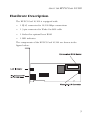
1
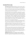
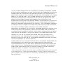
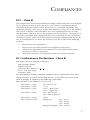
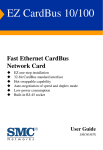
EZ PCI Card 10/100
Fast Ethernet PCI
Network Card
Plug-and-play installation
Remote LAN Wakeup support
On-board socket for optional Boot ROM
Auto-negotiation of speed and duplex mode
Low power consumption
ACPI and OnNow/ PC 98/99 compliant
User Guide
SMC1255TX, SMC1255TX/LP
EZ PCI Card 10/100
User Guide
From SMC’s EZ line of low-cost workgroup LAN solutions
6 Hughes
Irvine, CA 92618
Phone: (949) 707-2400
May 2001
Pub. # 150734-102
Copyright
Information furnished by SMC Networks, Inc. (SMC) is believed to be accurate and reliable.
However, no responsibility is assumed by SMC for its use, nor for any infringements of patents
or other rights of third parties which may result from its use. No license is granted by
implication or otherwise under any patent or patent rights of SMC. SMC reserves the right to
change specifications at any time without notice.
Copyright © 2001 by
SMC Networks, Inc.
6 Hughes, Irvine, CA.
All rights reserved. Printed in Taiwan
Trademarks:
SMC is a registered trademark; and EZ PCI Card is a trademark of SMC Networks, Inc. Other
product and company names are trademarks or registered trademarks of their respective
holders.
LIMITED WARRANTY
Limited Warranty
Limited Warranty Statement: SMC Networks, Inc. (“SMC”) warrants its products
to be free from defects in workmanship and materials, under normal use and
service, for the applicable warranty term. All SMC products carry a standard 90-day
limited warranty from the date of purchase from SMC or its Authorized Reseller.
SMC may, at its own discretion, repair or replace any product not operating as
warranted with a similar or functionally equivalent product, during the applicable
warranty term. SMC will endeavor to repair or replace any product returned under
warranty within 30 days of receipt of the product.
The standard limited warranty can be upgraded to a Limited Lifetime* warranty by
registering new products within 30 days of purchase from SMC or its Authorized
Reseller. Registration can be accomplished via the enclosed product registration
card or online via the SMC web site. Failure to register will not affect the standard
limited warranty. The Limited Lifetime warranty covers a product during the Life of
that Product, which is defined as the period of time during which the product is an
“Active” SMC product. A product is considered to be “Active” while it is listed on
the current SMC price list. As new technologies emerge, older technologies become
obsolete and SMC will, at its discretion, replace an older product in its product line
with one that incorporates these newer technologies. At that point, the obsolete
product is discontinued and is no longer an “Active” SMC product. A list of
discontinued products with their respective dates of discontinuance can be found at
http://www.smc.com/smc/pages_html/support.html.
All products that are replaced become the property of SMC. Replacement products
may be either new or reconditioned. Any replaced or repaired product carries
either a 30-day limited warranty or the remainder of the initial warranty, whichever
is longer. SMC is not responsible for any custom software or firmware,
configuration information, or memory data of Customer contained in, stored on, or
integrated with any products returned to SMC pursuant to any warranty. Products
returned to SMC should have any customer-installed accessory or add-on
components, such as expansion modules, removed prior to returning the product
for replacement. SMC is not responsible for these items if they are returned with the
product.
Customers must contact SMC for a Return Material Authorization number prior to
returning any product to SMC. Proof of purchase may be required. Any product
returned to SMC without a valid Return Material Authorization (RMA) number
clearly marked on the outside of the package will be returned to customer at
customer’s expense. For warranty claims within North America, please call our
toll-free customer support number at (800) 762-4968. Customers are responsible for
all shipping charges from their facility to SMC. SMC is responsible for return
shipping charges from SMC to customer.
WARRANTIES EXCLUSIVE: IF AN SMC PRODUCT DOES NOT OPERATE AS
WARRANTED ABOVE, CUSTOMER’S SOLE REMEDY SHALL BE REPAIR OR
REPLACEMENT OF THE PRODUCT IN QUESTION, AT SMC’S OPTION. THE
FOREGOING WARRANTIES AND REMEDIES ARE EXCLUSIVE AND ARE IN LIEU
LIMITED WARRANTY
OF ALL OTHER WARRANTIES OR CONDITIONS, EXPRESS OR IMPLIED, EITHER
IN FACT OR BY OPERATION OF LAW, STATUTORY OR OTHERWISE, INCLUDING
WARRANTIES OR CONDITIONS OF MERCHANTABILITY AND FITNESS FOR A
PARTICULAR PURPOSE. SMC NEITHER ASSUMES NOR AUTHORIZES ANY OTHER
PERSON TO ASSUME FOR IT ANY OTHER LIABILITY IN CONNECTION WITH
THE SALE, INSTALLATION, MAINTENANCE OR USE OF ITS PRODUCTS. SMC
SHALL NOT BE LIABLE UNDER THIS WARRANTY IF ITS TESTING AND
EXAMINATION DISCLOSE THE ALLEGED DEFECT IN THE PRODUCT DOES NOT
EXIST OR WAS CAUSED BY CUSTOMER'S OR ANY THIRD PERSON'S MISUSE,
NEGLECT, IMPROPER INSTALLATION OR TESTING, UNAUTHORIZED ATTEMPTS
TO REPAIR, OR ANY OTHER CAUSE BEYOND THE RANGE OF THE INTENDED
USE, OR BY ACCIDENT, FIRE, LIGHTNING, OR OTHER HAZARD.
LIMITATION OF LIABILITY: IN NO EVENT, WHETHER BASED IN CONTRACT OR
TORT (INCLUDING NEGLIGENCE), SHALL SMC BE LIABLE FOR INCIDENTAL,
CONSEQUENTIAL, INDIRECT, SPECIAL, OR PUNITIVE DAMAGES OF ANY KIND,
OR FOR LOSS OF REVENUE, LOSS OF BUSINESS, OR OTHER FINANCIAL LOSS
ARISING OUT OF OR IN CONNECTION WITH THE SALE, INSTALLATION,
MAINTENANCE, USE, PERFORMANCE, FAILURE, OR INTERRUPTION OF ITS
PRODUCTS, EVEN IF SMC OR ITS AUTHORIZED RESELLER HAS BEEN ADVISED
OF THE POSSIBILITY OF SUCH DAMAGES.
SOME STATES DO NOT ALLOW THE EXCLUSION OF IMPLIED WARRANTIES OR
THE LIMITATION OF INCIDENTAL OR CONSEQUENTIAL DAMAGES FOR
CONSUMER PRODUCTS, SO THE ABOVE LIMITATIONS AND EXCLUSIONS MAY
NOT APPLY TO YOU. THIS WARRANTY GIVES YOU SPECIFIC LEGAL RIGHTS,
WHICH MAY VARY FROM STATE TO STATE. NOTHING IN THIS WARRANTY
SHALL BE TAKEN TO AFFECT YOUR STATUTORY RIGHTS.
* SMC will provide warranty service for one year following discontinuance from the
active SMC price list. Under the limited lifetime warranty, internal and external
power supplies, fans, and cables are covered by a standard one-year warranty from
date of purchase.
SMC Networks, Inc.
6 Hughes
Irvine, CA 92618
COMPLIANCES
FCC - Class B
This equipment has been tested and found to comply with the limits for a Class B digital
device, pursuant to Part 15 of the FCC Rules. These limits are designed to provide
reasonable protection against harmful interference in a residential installation. This
equipment generates, uses and can radiate radio frequency energy and, if not installed
and used in accordance with instructions, may cause harmful interference to radio
communications. However, there is no guarantee that the interference will not occur in
a particular installation. If this equipment does cause harmful interference to radio or
television reception, which can be determined by turning the equipment off and on, the
user is encouraged to try to correct the interference by one or more of the following
measures:
•
Reorient the receiving antenna
•
Increase the separation between the equipment and receiver
•
Connect the equipment into an outlet on a circuit different from that to
which the receiver is connected
•
Consult the dealer or an experienced radio/TV technician for help
EC Conformance Declaration - Class B
SMC contact for these products in Europe is:
SMC Networks Europe,
Edificio Conata II,
Calle Fructuós Gelabert 6-8, 2o, 4a,
08970 - Sant Joan Despí,
Barcelona, Spain.
This information technology equipment complies with the requirements of the Low
Voltage Directive 73/23/EEC and the EMC Directive 89/336/EEC, and carries the CE
Mark accordingly. It conforms to the following specifications:
EMC: EN55024 (1998)/CISPR-22 (1995) Class B
IEC 61000-4-2 (1995)
IEC 61000-4-3 (1995)
IEC 61000-4-4 (1995)
IEC 61000-4-5 (1995)
IEC 61000-4-6 (1995)
IEC 61000-4-11 (1995)
4 kV CD, 8 kV AD
3 V/m
1.0 kV - (power line)
0.5 kV - (signal line)
2 kV - (line to line)
1 kV - (line to ground)
3 Vrms
Voltage dip
>95% - 10 ms
30% - 500 ms
60% - 100 ms
Voltage interruption >95% - 5000 ms
i
Industry Canada - Class B
This digital apparatus does not exceed the Class B limits for radio noise emissions from
digital apparatus as set out in the interference-causing equipment standard entitled
“Digital Apparatus”, ICES-003 of Industry Canada.
Cet appareil numérique respecte les limites de bruits radioélectriques applicables aux
appareils numériques de Classe B prescrites dans la norme sur le matérialbrouilleur:
“Appareils Numériques”, NMB-003 édictée par l’Industrie.
VCCI Class B Compliance (Japan)
ii
TABLE OF CONTENTS
TABLE
CONTENTS
OF
About the EZ PCI Card 10/100 . . . . . . . . . . . . . . . .1
Features and Benefits .
Hardware Description
LED Indicators .
Remote LAN Wakeup .
.
.
.
.
.
.
.
.
.
.
.
.
.
.
.
.
.
.
.
.
.
.
.
.
.
.
.
.
.
.
.
.
.
.
.
.
.
.
.
.
.
.
.
.
.
.
.
.
.
.
.
.
.
.
.
.
.
.
.
.
.
.
.
.
.
.
.
.
.
.
.
.
.
.
.
.
.
.
.
.
.
.
.
.
.
.
.
.
.
.
.
.
.
.
.
.
.
.
.
.
.
.
.
.
.
.
.
.
.
.
.
.
.
.
.
.
.
.
.
.
.
.
.
.
2
3
4
5
Installing the Card . . . . . . . . . . . . . . . . . . . . . . . . . .6
Equipment Checklist . . . . . . . . . . . . . . . . . . . . . . . . . . . . . . . . 6
Instructions . . . . . . . . . . . . . . . . . . . . . . . . . . . . . . . . . . . . . . . 7
Testing Program . . . . . . . . . . . . . . . . . . . . . . . . . . . . . . . . . . . 9
Troubleshooting . . . . . . . . . . . . . . . . . . . . . . . . . .10
PCI Compatibility . . . . . . . . . . . . . . . . . . .
Solutions for Common Problems . . . . . . .
Network Card Installation Problems
Network Connection Problems . . . .
.
.
.
.
.
.
.
.
.
.
.
.
.
.
.
.
.
.
.
.
.
.
.
.
.
.
.
.
.
.
.
.
.
.
.
.
.
.
.
.
.
.
.
.
.
.
.
.
.
.
.
.
.
.
.
.
.
.
.
.
10
12
12
13
Cable Specifications . . . . . . . . . . . . . . . . . . . . . . .14
Cable Types and Specifications . . . . . . . . . . . . . . . . . . . . . . . 14
Twisted-Pair Cable and Pin Assignments . . . . . . . . . . . . 14
Specifications . . . . . . . . . . . . . . . . . . . . . . . . . . . . .16
iii
TABLE OF CONTENTS
iv
ABOUT THE EZ PCI CARD 10/100
ABOUT THE
EZ PCI CARD 10/100
SMC’s EZ PCI Card 10/100 is a dual-speed Fast Ethernet card for
PCI local bus-compliant computers. A true plug-and-play device,
this card is auto-configurable upon power up and also supports
auto-negotiation to automatically select the optimum speed and
communication mode of an attached device. This EZ PCI Card 10/
100 complies with ACPI and OnNow PC98/ PC99 and also
supports Remote LAN Wakeup. By connecting the EZ PCI Card 10/
100 card’s Wake-On-LAN (WOL) cable, a WOL-enabled computer
can be managed remotely. Software can be loaded and updated,
configurations changed, data backed up and inventory checked,
all from a central location. See “Remote LAN Wakeup” on page 5
for more information.
1
ABOUT THE EZ PCI CARD 10/100
Features and Benefits
◆ Compatible with IEEE 802.3 Ethernet and IEEE 802.3u Fast
Ethernet standards
◆ Full- and half-duplex support for both 10 Mbps and 100 Mbps
speeds
◆ Auto-negotiation selects 10/100 Mbps and full/half duplex
automatically
◆ Supports full-duplex operation for up to 200 Mbps of
bandwidth
◆ Automatic configuration set up using the PCI computer’s BIOS
setup program
◆ Supports Remote LAN Wakeup for efficient centralized desktop
management
◆ Supports optional boot ROM for remote booting of a
management PC’s operating system
◆ ACPI and OnNow/PC98/99 compliance reduces power
consumption
2
ABOUT THE EZ PCI CARD 10/100
Hardware Description
The EZ PCI Card 10/100 is equipped with:
•
1 RJ-45 connector for 10/100 Mbps connections
•
1 3-pin connector for Wake-On-LAN cable
•
1 Socket for optional boot ROM
•
1 LED indicator
The components of the EZ PCI Card 10/100 are shown in the
figure below:
3
ABOUT THE EZ PCI CARD 10/100
LED Indicators
The SMC1255TX includes one status LED indicator, as described in
the following figure and table.
4
Status
Description
On Amber
Indicates a valid 10BASE-T link
Flashing Amber
Indicates 10 Mbps network activity
On Green
Indicates a valid 100BASE-TX link
Flashing Green
Indicates 100 Mbps network activity
ABOUT THE EZ PCI CARD 10/100
Remote LAN Wakeup
Remote LAN Wakeup capability is a key feature of a centrally
managed PC environment. This technology enables networked
PCs to be “woken up” from a sleep or powered-off state so they
can be managed from a central location, at any time of the day or
night.
To employ Remote LAN Wakeup, three elements are required:
•
Desktop management software that can send a “wake-up”
packet to a PC.
•
A Wake-On-LAN enabled PC motherboard that can supply
low-level auxiliary power to a network card when the PC is
powered off.
•
A Wake-On-LAN network card that can recognize a wake-up
packet and signal the PC to power up.
A Wake-On-LAN enabled PC is never completely powered off, it
maintains a low-level auxiliary power supply to the motherboard.
The 3-wire Wake-On-LAN cable provides one line for the network
card auxiliary power and one line for the card wake-up signal, the
other line is ground. Even if the PC is powered off the network
card is always active and monitoring the network. When a
wake-up packet is detected, the card signals the motherboard to
power up the PC. With the PC powered on, maintenance and
other support tasks can be performed.
5
INSTALLING THE CARD
INSTALLING
THE
CARD
Equipment Checklist
After unpacking the EZ PCI 10/100 card, check the contents of the
box to be sure you have received the following components:
•
EZ PCI 10/100 card SMC1255TX
•
Wake-On-LAN cable
•
SuperDisk™ network drivers diskette
•
SMC Warranty Registration Card
•
User Guide
Immediately inform your dealer in the event of any incorrect,
missing or damaged parts. If possible, please retain the carton and
original packing materials in case there is a need to return the
product.
Please fill out and return the Warranty Registration Card to SMC or
register on SMC’s Web site. The EZ PCI Card 10/100 is covered by
a limited lifetime warranty.
6
INSTALLING THE CARD
Instructions
Warnings:
•
Network cards are sensitive to static electricity. To protect the
card, avoid touching its electrical components and always
touch the metal chassis of your computer before handling the
card.
•
Back up your driver diskette and use the copy as the working
diskette to protect the original from accidental damage.
1. Switch off the computer, unplug the power cord, and remove
the computer’s cover.
2. Select an unused PCI bus-master slot and remove its protective
bracket.
3. Carefully insert the card and press until all the edge connectors
are firmly seated inside the slot. Then screw the card’s bracket
securely into the PC’s chassis.
4. Attach the Wake-On-LAN cable (optional). If you require
Wake-On-LAN capability from a powered-off state, attach one
end of the 3-pin Wake-On-LAN cable to the connector on the
top edge of the card, and the other end to the “5 V Standby”
connector on the computer’s motherboard. Refer to your
computer’s installation manual to locate this connector.
7
INSTALLING THE CARD
5. Connect the EZ PCI Card 10/100 directly to a 10BASE-T or
100BASE-TX hub or switch using UTP cable (Category 3, 4 or 5
for 10BASE-T; Category 5 for 100BASE-TX). The maximum
allowable length of UTP cable connections is 100 meters
(328 ft). When inserting an RJ-45 plug, be sure the tab on the
plug clicks into position to ensure that it is properly seated.
6. Replace the computer’s cover and power it on. The EZ PCI
Card 10/100 should be automatically configured by the host
computer’s BIOS. However, if you have an older computer,
you may have to manually configure the computer’s BIOS
settings. See “Troubleshooting” on page 10.
7. The SMC SuperDisk that accompanies the EZ PCI Card 10/100
contains all the network operating system drivers supported by
this card. Please read the “RELEASE.TXT” file on the diskette
for a list of all drivers. Also, a text file is included with each
driver to detail the proper installation procedure. Any new or
updated drivers can be downloaded from SMC’s Web site (see
the back cover of this guide).
8
INSTALLING THE CARD
Testing Program
If the EZ PCI Card 10/100 is not automatically configured by the
host PC, or there is a problem with the card, run the DOS-based
Testing Program to help view the PC’s BIOS settings of this card.
Boot the computer to a full DOS environment (not a DOS
window) and run the Testing Program, SET1255.EXE, on the SMC
SuperDisk. Should any of the diagnostic tests fail, reboot your
computer and run the diagnostics again to see if the problem
persists. If it does, record the failure indicated and contact SMC’s
Technical Support for assistance.
9
TROUBLESHOOTING
TROUBLESHOOTING
PCI Compatibility
Early PCI BIOS versions do not properly support the PCI
specification and may “hang” when a network card driver tries to
load. If this occurs, make sure your BIOS correctly supports the
PCI Local Bus Specification (v2.0 or later) and upgrade your
computer BIOS to the latest version.
Some PCI computers are not self-configuring and require you to
perform some or all of the following functions by motherboard
jumper changes and/or BIOS Setup program configuration:
10
◆
Verify that the PCI slot is an enabled bus-master slot and not a
slave PCI slot. The EZ PCI Card 10/100 must be installed in a
PCI bus-master slot. In some computers the PCI slot must be
configured to enable bus mastering. Refer to your PC’s manual
and check the PCI BIOS Setup program to be sure the PCI slot
is an enabled busmaster slot.
◆
In some computers, you may be required to disable Plug-andPlay in the BIOS Setup program if resources are not properly
assigned between the network card and other installed cards.
◆
Some computers may require you to reserve interrupts and
memory addresses for installed ISA cards to prevent PCI cards
from using the same settings. Refer to your PC’s manual and
check the PCI BIOS Setup program configuration options for
ISA cards.
◆
Make sure the PCI slot is configured to support INTA.
TROUBLESHOOTING
◆
Ensure that INTA for the slot is assigned to a free interrupt
(IRQ) number.
◆
Check the BIOS Setup program’s PCI parameters for the slot
where the EZ PCI Card 10/100 network card is installed. Ensure
that the slot is configured for level-triggered interrupts instead
of edge-triggered interrupts. An example of typical PCI
parameters follows:
PCI Slot #:
(slot number where the network card
is installed)
Master:
Enabled
Slave:
Enabled
Latency Timer:
40 (range is 20 to 255)
Interrupt Type:
Level-Triggered
Interrupt Number:
(choose any number the BIOS Setup
supplies that does not conflict with
another installed card)
Note that the wording of these parameters varies with different
computers, and not all parameters may be configurable.
Always consult your computer manual for information on
changing motherboard jumper settings and BIOS Setup program
parameters for use with PCI network cards. If you set a
motherboard jumper and modify the computer’s BIOS Setup, make
sure the jumper and BIOS settings match.
11
TROUBLESHOOTING
Solutions for Common Problems
Problems are often caused by cabling errors, conflicts with other
devices installed in the same computer, or software that has been
configured incorrectly. If you encounter a problem with the EZ
PCI Card 10/100 network card, use the following checklists to
identify and correct the problem.
Network Card Installation Problems
If your computer cannot find the EZ PCI Card 10/100, or the
network driver does not install correctly, check the following items
before contacting SMC Technical Support.
12
◆
Make sure the card is securely seated in the PCI slot. Check for
any hardware problems, such as physical damage to the card’s
edge connector.
◆
Try the card in another PCI bus-master slot. If this fails, test with
another EZ PCI Card 10/100 card that is known to operate
correctly.
◆
Check for resource conflict in the PCI configuration. See section
“PCI Compatibility” in this chapter.
◆
Make sure your computer is using the latest BIOS available.
◆
If there are other network cards in the computer, they may be
causing conflict. Remove all other cards from the computer and
test the EZ PCI Card 10/100 separately.
◆
Check for a defective computer or PCI bus by trying the
network card in another computer that is known to operate
correctly.
TROUBLESHOOTING
Network Connection Problems
There may be a network connection problem if the LED on the
card’s bracket does not light, or if you cannot access any network
resources from the computer. Check the following items before
contacting SMC Technical Support.
◆
Be sure you are using Category 5 cable for 100 Mbps
connections, and that the length of any cable does not exceed
100 m (328 ft).
◆
Inspect all network cables and connections. Make sure the
network cable is securely attached to the card’s connector.
◆
Make sure the correct network card driver is installed for your
operating system. If necessary, try reinstalling the driver.
◆
Make sure the computer and other network devices are
receiving power. If you suspect a power outlet to be faulty,
plug another device into it to verify that it is working.
◆
If the the network card’s speed or duplex mode has been
configured manually, check that it matches that of the attached
network device port. Note that it is recommended to set the
card to auto-negotiation when installing the network driver.
◆
The port on the network device that the card is attached to may
be defective. Try using another port on the device.
◆
If you cannot access a Windows or NetWare service on the
network, check that you have enabled and configured the
service correctly. If you cannot connect to a particular server,
ensure that you have access rights and a valid ID and password.
◆
If you cannot access the Internet, be sure you have configured
your system for TCP/IP.
13
CABLE SPECIFICATIONS
CABLE SPECIFICATIONS
Cable Types and Specifications
Cable Types and Specifications
Cable
Type
Max. Length
Connector
10BASE-T
Cat. 3, 4, 5 100-ohm UTP
100 m (328 ft)
RJ-45
100BASE-TX
Cat. 5 100-ohm UTP
100 m (328 ft)
RJ-45
Twisted-Pair Cable and Pin Assignments
DO NOT plug a phone jack connector into any RJ-45 port. Use
only twisted-pair cables with RJ-45 connectors that conform with
FCC standards.
For 10BASE-T/100BASE-TX connections, a twisted-pair cable must
have two pairs of wires. Each wire pair is identified by two
different colors. For example, one wire might be red and the other
red with white stripes. Also, an RJ-45 connector must be attached
to both ends of the cable.
Caution: Each wire pair must be attached to the RJ-45 connectors
in a specific orientation.
14
CABLE SPECIFICATIONS
The figure below illustrates how the pins on the RJ-45 connector
are numbered. Be sure to hold the connectors in the same
orientation when attaching the wires to the pins.
With 10BASE-T/100BASE-TX cable, pins 1 and 2 are used for
transmitting data, and pins 3 and 6 for receiving data. The “+” and
“-” signs in the tables below are used to represent the polarity of
the wires that make up each wire pair.
RJ-45 Pin Assignments
Pin
Assignment*
1
Tx+
2
Tx-
3
Rx+
6
Rx-
15
SPECIFICATIONS
SPECIFICATIONS
Ports
1 RJ-45 for 10BASE-T and 100BASE-TX
Host Interface
PCI Bus compliant to PCI spec. 2.2.
LED
Link, Speed, Activity
Data Bus Access
32-bit bus mastering
Size (without bracket)
119.92 x 42.98 mm (4.72 x 1.69 in.)
Weight
47 g (1.66 oz)
Power Requirements
5 VDC, 125 mA (typical)
Temperature
Operating: 0 to 55 °C (32 to 131 °F)
Storage: -20 to 65 °C (-4 to 149 °F)
Humidity
10% to 90% non-condensing
Standards
IEEE 802.3 10BASE-T
IEEE 802.3u 100BASE-TX
IEEE 802.3x 100BSE-TX Flow Control support
IEEE 802.1p/Q Quality of Service (QoS)
PCI bus V 2.2, ACPI
OnNow/PC 98, PC 99
DMI 2.0, Wired for Management 2.0
16
SPECIFICATIONS
Compliances
FCC Class B
VCCI Class B
CE Mark
CISPR 22 Class B
Warranty
Limited lifetime
NetWare ODI Drivers
Novell NetWare 3.1X to 5.x
Netware Lan WorkPlace
Novell DOS Client
Novell Lan Analyzer
Server 3.1x to 5.x
Unix Drivers
Linux
FreeBSB
SCO Unix 5.0x
SCO Unixware 7.x
NDIS Drivers
Windows 95 OSR2
Windows 98
Windows 2000
Windows ME
Windows NT 3.51, 4.0
Microsoft Lan Manager
IBM LAN Server
IBM LAN Support
DEC PATHWORKS
Windows for Workgroups 3.11
17
SPECIFICATIONS
Packet Drivers
FTP PC/TCP
NCSA TCP/IP
18
FOR TECHNICAL SUPPORT, CALL:
From U.S.A. and Canada (24 hours, 7 days a week)
(800) SMC-4-YOU; (949) 707-2400; (949) 707-2460 (Fax)
From Europe (8:00 AM - 5:30 PM UK Greenwich Mean Time)
44 (0) 1188 748740; 44 (0) 1189 748741 (Fax)
INTERNET
E-mail address:
[email protected]
[email protected]
Driver updates:
http://www.smc.com/support.html
World Wide Web:
http://www.smc.com/
FTP Site:
ftp.smc.com
FOR LITERATURE OR ADVERTISING RESPONSE, CALL:
U.S.A. and Canada:
Spain:
UK:
Southern Europe:
Central/Eastern Europe:
Nordic:
Middle East:
South Africa:
PRC:
Taiwan:
Asia Pacific:
Korea:
Japan:
Australia:
India:
6 Hughes
Irvine, CA 92618
(800) SMC-4-YOU;
34-93-477-4920;
44 (0) 1188 748700;
33 (1) 41.18.68.68;
49 (0) 89 92861-200;
46 (8) 564 33145;
971-48818410;
27 (0) 11-3936491;
86-10-6235-4958;
886-2-2747-4780;
(65) 238 6556;
82-2-553-0860;
81-45-224-2332;
61-2-9416-0437;
91-22-8204437;
Fax (949) 707-2460
Fax 34-93-477-3774
Fax 44 (0) 1189 748701
Fax 33 (1) 41.18.68.69
Fax 49 (0) 89 92861-230
Fax 46 (8) 87 62 62
Fax 971-48817993
Fax 27 (0) 11-3936491
Fax 86-10-6235-4962
Fax 886-2-2747-9220
Fax (65) 238 6466
Fax 82-2-553-7202
Fax 81-45-224-2331
Fax 61-2-9416-0474
Fax 91-22-8204443
Model Numbers:
SMC1255TX, SMC1255TX/LP
6 Hughes
Irvine, CA 92618
Publication Number: 150734-102 E052001-R01
xxii