1
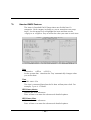
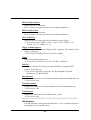
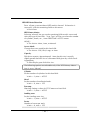
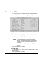
MS52/MS52N & MS54/MS54N
Pentium 4 Processor
Based DDR MAIN BOARD
User's Manual
Shuttle® MS52/MS52N & MS54/MS54N
Pentium 4 , 478-pin processor based DDR Mainboard
Manual Version 1.0
Copyright
Copyright© 2002 by Shuttle® Inc. All Rights Reserved.
No part of this publication may be reproduced, transcribed, stored in a retrieval system,
translated into any language, or transmitted in any form or by any means, electronic,
mechanical, magnetic, optical, chemical, photocopying, manual, or otherwise, without
prior written permission from Shuttle® Inc.
Disclaimer
Shuttle® Inc. shall not be liable for any incidental or consequential damages resulting from the
performance or use of this product.
This company makes no representations or warranties regarding the contents of this manual.
Information in this manual has been carefully checked for reliability; however, no guarantee is
given as to the correctness of the contents. In the interest of continued product improvement,
this company reserves the right to revise the manual or include changes in the specifications
of the product described within it at any time without notice and without obligation to notify any
person of such revision or changes. The information contained in this manual is provided for
general use by the customers.
Trademarks
Shuttle is a registered trademark of Shuttle Inc.
Intel, Pentium is a registered trademarks of Intel Corporation.
SiS is a registered trademarks of SiS Corporation.
PS/2 is a registered trademark of IBM Corporation.
AWARD is a registered trademark of Award Software Inc.
Microsoft and Windows are registered trademarks of Microsoft Corporation.
General Notice: Other brand and product names used herein are for identification
purposes only and may be trademarks of their respective owners.
M647
TABLE OF CONTENTS
WHAT'S IN THE MANUAL .................................................................... 5
Quick Reference ............................................................................................... 5
About This Manual ........................................................................................... 5
1 INTRODUCTION ................................................................................ 6
1.1 TO DIFFERENT USERS ............................................................................. 6
FIRST-TIME DIY SYSTEM BUILDER ........................................................... 6
EXPERIENCED DIY USER ........................................................................ 6
SYSTEM INTEGRATOR............................................................................... 6
1.2 ITEM CHECKLIST ....................................................................................... 7
2 FEATURES ........................................................................................ 8
2.1 SPECIFICATIONS ....................................................................................... 8
3 HARDWARE INSTALLATION ...............................................................11
3.1 STEP BY STEP INSTALLATION ........................................................................11
Accessories of MS52/MS52N & MS54/MS54N........................................... 11
STEP 1 CPU Installation ........................................................................ 12
STEP 2 Set Jumpers ............................................................................. 14
STEP 3 Install DDR SDRAM System Memory........................................ 14
STEP 4 Install Peripherals in System Case ............................................ 15
STEP 5 Mount the Mainboard on the Computer Chassis ........................ 16
STEP 6 Connect Front Panel Switches/LEDs/Speaker/USB ................. 17
STEP 7 Connect IDE and Floppy Disk Drives ........................................ 18
STEP 8 Connect Other Internal Peripherals............................................ 18
STEP 9 Connect the Power Supply ........................................................ 19
STEP 10 Install Add-on Cards in Expansion Slots .................................. 20
STEP 11 Connect External Peripherals to Back Panel .......................... 21
STEP 12 First Time System Boot Up ..................................................... 22
STEP 13 Install Drivers & Software Components ................................... 23
-1-
3.2 JUMPER SETTINGS ................................................................................. 24
JUMPERS & CONNECTORS GUIDE .................................................... 25
Jumpers
Clear CMOS Setting (JP1) ................................................................... 28
BIOS Write Protection (JP3) .................................................................. 28
Back-Panel Connectors
PS/2 Keyboard & PS/2 Mouse Connectors ............................................ 29
COM1 Port Connector ........................................................................... 29
Parallel Port Connector .......................................................................... 29
Line-out port connector ......................................................................... 29
Line-in port connector ............................................................................ 30
Mic-in port connector ............................................................................. 30
GAME/MIDI port connector .................................................................... 30
LAN port connector ................................................................................ 30
USB port1 / USB port2 connectors......................................................... 30
Front-Panel Connectors
ATX power on/off switch connector (PWRSW) ....................................... 31
Green LED connector (GRN LED) ......................................................... 31
HDD LED connector (HDD LED) ........................................................... 31
Hardware reset connector (RST) ............................................................ 32
Speaker connectorn (SPEAKER1) ........................................................ 32
ACPI LED (SJ1) .................................................................................... 32
Front-oriented Microphone/Line-out port header (AUDIO1) .................... 33
Extended USB headers (USB2/3) .......................................................... 33
Internal Peripherals Connectors
Enhanced IDE and Floppy Connector ................................................... 34
Other Connectors
-2-
ATX Power Supply Connectors (ATX1/ATX2) ........................................ 35
Audio CD_IN connectors (CDIN1/CDIN2) .............................................. 35
Wake-on-Modem connector (WOM1) ..................................................... 36
Wake-on-Lan connector (WOL1) ............................................................ 36
Cooling Fan Connectors for CPU (CPUFAN1), Case (CASFAN1/
PWRFAN1) ........................................................................................... 36
IR header (IR1) ...................................................................................... 37
3.3 SYSTEM MEMORY CONFIGURATION ..................................................... 38
1. INSTALL MEMORY ............................................................................ 38
2. UPGRADE MEMORY ........................................................................ 38
4 SOFTWARE UTILITY ...................................................................... 39
4.1 Mainboard CD Overview ......................................................................... 39
4.2 Install Mainboard Software ..................................................................... 40
4.3 Install VGA Device Driver ................................................................................. 41
4.4 Install SIS AGP Driver ....................................................................................... 42
4.5 Install Audio Device Driver .............................................................................. 43
4.6 Install LAN Driver ............................................................................................... 44
4.7 View the User's Manual .................................................................................... 45
5 BIOS SETUP ................................................................................... 46
5.1 ENTER BIOS ............................................................................................. 46
5.2 THE MAIN MENU ...................................................................................... 47
STANDARD CMOS FEATURES ............................................................... 49
ADVANCED BIOS FEATURES ................................................................. 52
ADVANCED CHIPSET FEATURES .......................................................... 56
INTEGRATED PERIPHERALS .................................................................. 58
POWER MANAGEMENT SETUP .............................................................. 62
-3-
PNP/PCI CONFIGURATION....................................................................... 65
PC HEALTH STATUS ................................................................................ 67
FREQUENCY/VOLTAGE CONTROL ......................................................... 68
LOAD FAIL-SAFE DEFAULTS .................................................................. 69
LOAD OPTIMIZED DEFAULTS ................................................................. 69
SET PASSWORD ..................................................................................... 70
SAVE & EXIT SETUP ................................................................................ 71
EXIT WITHOUT SAVING ............................................................................ 71
-4-
WHAT’S IN THE MANUAL
Quick Reference
Hardware Installation >> Step-by-Step ................................................ Page 11
Jumper Settings >> A Closer Look ...................................................... Page 25
Drivers/Software Utilities >> How to Install ......................................... Page 39
BIOS Setup >> How to Configure ......................................................... Page 46
About This Manual
For First-Time DIY System Builder ......................................................... Page 6
For Experienced DIY User ...................................................................... Page 6
For System Integrator ............................................................................. Page 6
-5-
1 INTRODUCTION
1.1 To Different Users
First-Time DIY System Builder
Welcome to the DIY world! Building your own computer system is not as difficult as you may think. To make your first computer DIY experience successful,
right from the start, we have designed the 3.1 Hardware Installation section in
a step-by-step fashion for all the first-time DIY system builders. Prior to installation, we also suggest you to read the whole manual carefully to gain a complete understanding of your new Shuttle MS52/MS52N & MS54/MS54N
mainboard.
Experienced DIY User
Congratulate on your purchase of the Shuttle MS52/MS52N & MS54/MS54N
mainboard. You will find that installing your new Shuttle MS52/MS52N & MS54/
MS54N mainboard is just easy. Bundled with an array of onboard functions,
the highly-integrated MS52/MS52N & MS54/MS54N mainboard provides you
with a total solution to build the most stable and reliable system. Refer to sections 3.2 Jumper Settings and Chapter 4 Drivers/Software Utilities to find out
how to get the best out of your new mainboard. Chapter 5 BIOS Setup also
contains the relevant information on how to tune up your system to achieve
higher performance.
System Integrator
You have wisely chosen Shuttle MS52/MS52N & MS54/MS54N to construct
your system. Shuttle MS52/MS52N & MS54/MS54N incorporates all the stateof-the-art technology of the SiS 650GX or SiS651 Northbridge and SiS962L
Southbridge chipsets from SiS. It integrates the most advanced functions you
can find to date in a compact Micro ATX board.
The mainboard may support either of the Northbridge and Southbridge
chipset mentioned below. Please refer below for the combination and
respective details:
• MS54N/ MS54 is equipped with SiS650GL and SiS962L. Meanwhile, only
MS54N is with LAN controller. In the manual, if there are some standards,
characters, equipment or software only appeared or adopted by MS54N; it will
be mentioned (MS54N only).
• MS52N/ MS52 is equipped with SiS651 and SiS962L. Meanwhile, only
MS52N is with LAN controller. In the manual, if there are some standards,
characters, equipment or software only appeared or adopted by MS52N; it will
be mentioned (MS52N only).
-6-
1.2 Item Checklist:
Check all items with you MS52/MS52N & MS54/MS54N mainboard to make
sure nothing is missing. The complete package should include:
PSKBM1
CPU FAN1
AMP
COM1
IDE2
IDE1
AUDIO 1
DIMM1
DIMM2
LED1
1
0229
LF-H50X
USB
AMP
1
1
ATX 2
R
- One piece of Shuttle
MS52/MS52N & MS54/MS54N Mainboard
PCI1
SiS
PANEL1
USB2 USB3
IR 1
1
1
JP 1
W49F002UP12B
211288201
212GHS A
CNR1
JP 3
PCI3
Winbond
1
S TER Y
K T BAT STD
IUM A N1 32
LITH JAP C r20
1
WOM1
1
1
1
1
WOL1
PWRFAN1
FDD1
- One piece of ATA100/66/33 Ribbon Cable
- One piece of Floppy Ribbon Cable
- One piece of twin ports USB Cable (optional)
- I/O Shielding
- MS52/MS52N & MS54/MS54N User's Manual
- One piece of Bundled CD-ROM with containing:
Ø MS52/MS52N & MS54/MS54N user manual saved in PDF format
Ø SiS Chipset driver
Ø SiS AGP driver
Ø AC'97 Audio Device driver
Ø LAN driver (MS52N/MS54N only)
Ø Award Flashing Utility
-7-
1
SJ 1
PCI2
SIS'01
PMD0047
0201EA AZ
CAS FAN1
SP EAKER1
RMC
C
2 FEATURES
MS52/MS52N & MS54/MS54N mainboard is carefully designed for the demanding PC
user who wants high performance and maximum intelligent features in a compact
package.
2.1 Specifications
- CPU Support
Intel Pentium 4/Celeron, 478-pin processors with 400 MHz FSB.(MS54/
MS54N)
Intel Pentium 4/Celeron, 478-pin processors with 400 /533MHz FSB.(MS52/
MS52N)
- Chipset
Features SiS 650GL N.B. and SiS 962L S.B.(MS54/MS54N).
Features SiS 651 N.B. and SiS 962L S.B.(MS52/MS52N).
- Onboard Lan
Realtek RTL8100B, support 10Mb/s and 100Mb/s operation.
- Jumperless CPU Configuration
Soft-configuration FSB (The FSB speed is software configurable from 100MHz
to 133MHz in the Frequency/Voltage Control of BIOS setup program.)
- AC'97 Link for Audio and Telephony CODEC
AC'97 2.2 compliant.
Spread independent PCI functions for Moden and 4 channel Audio.
- Versatile Memory Support
Two 184-pin DIMM slots to support up to 2GB of PC1600 and PC2100 compliant DDR SDRAM module (MS54/MS54N).
Two 184-pin DIMM slots to support up to 2GB of PC1600 and PC2100 or
PC2700 compliant DDR SDRAM module (MS52/MS52N).
- AGP Expansion Slot
Provides one 32-bit AGP slot which supports 4x AGP devices.
- PCI Expansion Slots
Provides three 32-bit PCI slots.
-8-
- CNR Expansion Slot
Provides one Communication and Network Riser (CNR) slot.
- 6 USB2.0 Interface Onboard
Ø 2 USB connectors on back-panel and two sets of dual USB ports header
on board.
- I/O Interface
Provides a variety of I/O interfaces:
Ø 1 PS/2 mouse connector
Ø 1 PS/2 keyboard connector
Ø 1 serial port.
Ø 1 VGA port.
Ø 1 parallel port..
Ø 1 MIDI/GAME port.
Ø 2 USB ports.
Ø 1 LAN port.
Ø 1 Line-Out port.
Ø 1 Line-In port.
Ø 1 Mic-In port.
- PCI Bus Master IDE Controller Onboard
Two Ultra DMA 133/100/66 Bus Master Dual-channel IDE ports provide support to a maximum of four IDE devices (one Master and one Slave per channel).
The IDE Bus implements data transfer speeds of up to 133/100/66 MB/sec and
also supports Enhanced PIO Modes.
80-pin Cable Backward Compatible Legacy ATAPI Devices, ATAPI IDE CDROM, CD-R, CD-RW, and LS-120 Supports.
- ATX Power Supply Connector
ATX power supply unit can connected to the onboard 20-pin Pentium 4
standard ATX power connectors, supporting Suspend and Soft-On/Off by
dual-function power button.
-9-
- Advanced Configuration and Power Interface
Features four power saving modes: S1 (Snoop), S3 (Suspend to RAM), S4
(Suspend to DISK), and S5 (Soft-Off). ACPI provides more efficient Energy
Saving Features controlled by your operating system that supports OS Direct
Power Management (OSPM) functionality.
- System BIOS
Provides licensed Award BIOS V6.0 PG on 2Mb Flash core and supports
Green PC, Desktop Management Interface (DMI).
- Form Factor
System board conforms to Micro ATX specification.
Board dimension: 244mm x244mm.
- Advanced Features
Ø Low EMI - Built in spread spectrum and automatic clock shut-off of
unused PCI/SDRAMS slots to reduce EMI.
Ø Dual Function Power Button - The system can be in one of two states,
one is Suspend mode and the other is Soft-Off mode. Pushing the power
button for less than 4 seconds places the system into Suspend mode.
When the power button is pressed for longer than 4 seconds, the system
enters Soft-Off mode.
Ø Modem Ring Power-On (WOM1) - The system can be powered on
automatically by the activation of modem ringing.
Ø Wake-on-Lan (WOL1) - The onboard WOL connector can be attached to
a network card that supports this function to wake up the system via LAN.
Ø CPU Host/DRAM/PCI Clock Setting - This item allows users to adjust
CPU Host Clock, DRAM, and PCI Clock in BIOS.
Ø CPU Multiplier Setting - This item allows users to adjust CPU Multiplier
in BIOS.
- Intelligent Features
Ø Voltage Monitoring - Monitors various voltages of key elements, such as
the CPU, and other critical system voltage levels to ensure stable current
passing through mainboard components.
Ø Fan Status Monitoring - To prevent CPU from overheating, the CPU fan
is monitored for RPM (CPU Cooling FAN with RPM sensor is required.)
Ø Temperature Monitoring - This item allows users to make sure whether
the CPU or system runs in a suitable temperature.
- 10 -
3 HARDWARE INSTALLATION
Before removing or installing any of these devices including CPU, DIMMs, Add-On
Cards, Cables, please make sure to unplug the onboard power connector.
This section outlines how to install and configure your mainboard. Refer to the following
mainboard layout to help you to identify various jumpers, connectors, slots, and ports.
Then follow these steps designed to guide you through a quick and correct installation of
your system.
3.1 Step-by-Step Installation
Accessories Of MS52/MS52N & MS54/MS54N
Extended USB Header - USB 2\3
CPU FAN1
COM1
LED1
Parallel Connector
LF-H50X
1
SiS
USB2
USB3
PANEL1
IR 1
1
1
Clear CMOS - JP1
JP 1
CNR1
Winbond
RY
T S TTE
K MBA 1 STD
N 2
HIU P A 03
LIT JA Cr2
W49F002U P12B
211288201
212GHSA
PCI3
1
WOM1
1
Wake on Modem-WOM1
1
WOL1
PWRFAN1
1
1
1
JP 3
FDD1
1
SPEAKER1
SIS'01
PMD0047
0201EA A Z
SJ 1
R MC
C
PCI2
Front Panel Header -PANEL1
R
PCI1
RTL8100 LAN Controller
(MS52N &MS54N Only)
CNR Slot
1
ATX 2
SiS 962L
Three PCI Slots
1
USB
AMP
USB & LAN(MS52N & MS54N Only)
Connectors
ATX Power Connector-ATX2
One AGP 4X Slot
0229
Front-oriented Microphone/
Line-out port header-Audio1
AUDIO 1
Line-Out/Line-In/Mic-In
Game/MIDI Connectors
DIMM1
DIMM2
VGA Port
IDE2
IDE1
MS52
ATX 12V Power Connector
-ATX1
Two IDE Connectors
SiS 651/SiS650GL
Speaker Connector-SPEAKER1
Serial Port Connector
(COM1)
PSKBM1
AMP
CAS FAN1
Floppy Connector
BIOS Write Protection-JP3
IR Connector-IR1
- 11 -
Case Fan Connector1-PWRFAN1
Case Fan Connector2-CASFAN1
PS/2 Keyboard/
PS/2 Mouse Connectors
CPU Fan
Connector-CPUFAN1
Two DDR DIMM Slots
Socket 478
Step 1
CPU Installation:
This mainboard supports Intel Pentium 4/Celeron , Socket 478 series CPU.
Please follow the step as below to finish CPU installation.
Be careful of CPU orientation when you plug it into CPU socket.
1. Pull up the CPU socket lever and up to 90-degree angle.
CPU socket lever up to
90 degree
2. Locate Pin 1 in the socket and look for a black dot or cut edge on the CPU
upper interface. Match Pin 1 and cut edge, then insert the CPU into the
socket.
CPU pin 1 and cut edge
- 12 -
3. Press down the CPU socket lever and finish CPU installation.
Note: If you do not match the CPU socket Pin 1 and CPU cut edge
well, it may damage the CPU.
4. The Intel Pentium4/Celeron processor requires a set of heatsink/fan to
ensure proper cooling of the processor. If heatsink/fan have not been
already bundled with your CPU, you must purchase the heatsink/fan
separately and have it in stalled. Plug the cable through the heatsink/fan in
the CPU fan power connector located nearby. Note that there are several
types of CPU fan connectors. Normally, if your mainboard supports
the bard ware monitoring function, a 3-pin fan power connector should
allow your system to detect the CPU fan's speed. The CPU fan can also
run with a 2-pin fan power connector, however, detection of CPU fan's
speed is not supported. Another type of CUP fan may feature a large 4-pin
fan power connector, which does not support CPU fan's speed detection
and must be directly connected to the system's power supply unit.
- 13 -
Step 2.
Set Jumpers
The default jumper settings have been set for the common usage standard of
this mainboard. Therefore, you do not need to reset the jumpers unless you
require special adjustments as any of the following cases:
1. Clear CMOS
2. BIOS Write Protect
For first-time DIY system builders, we recommend that you do not change the
default jumper settings if you are not totally familiar with the mainboard
configuration procedures. The factory-set default settings are tuned for optimum system performance. For the advanced users who wish to customize
their system, section 3.2 Jumper Settings will provide detailed information on
how to configure your mainboard manually.
Step 3
Install DDR SDRAM System Memory
To install memory, insert DDR SDRAM memory module(s) in DIMM slot(s).
Note that DDR SDRAM modules are directional and will not go in the DIMM
slots unless properly oriented. After the module is fully inserted into the
DIMM slots, lift the clips of both sides of the DIMM slot to lock the module in
place.
DDR SDRAM
- 14 -
Step 4
Install Internal Peripherals in System Case
Before you install and connect the mainboard into your system case, we
recommend that you first assemble all the internal peripheral devices into the
computer housing, including but not limited to the hard disk drive (IDE/
HDD), floppy disk drive (FDD), CD-ROM drive, and ATX power supply unit.
This will greatly facilitate in making the connections to the mainboard described below.
To install IDE & FDD drives, follow this procedure:
1. Set the required jumpers on each device according to the instructions
provided by the manufacturer. (IDE devices, HDD, and CD-ROM, have to
set jumpers to Master or Slave mode depending on whether you install
more than one device of each kind.)
2. Connect IDE cable and FDD cable on the back-panel of the internal
peripheral devices to the corresponding headers on board. Note that the
cable should be oriented with its colored stripe (usually red or magenta)
connected to pin#1 both on the mainboard IDE or FDD connector and on
the device as well.
3. Connect an available power cable from your system power supply unit
to the back-panel of each peripheral device. Note that the power cable is
directional and cannot fit in if not properly positioned.
- 15 -
Step 5
Mount the Mainboard on the Computer Chassis
1. You may find that there are a lot of different mounting hole positions
both on your computer chassis and on the mainboard. To choose
correct mounting holes, the key point is to keep the back-panel of the
mainboard in a close fit with your system case, as shown below.
2. After deciding on the proper mounting holes, position the studs between
the frame of the chassis and the mainboard. The studs are used to fix the
mainboard and to keep a certain distance between the system chassis and
the mainboard, in order to avoid any electrical shorts between the board
and the metal frame of the chassis. (If your computer case is already
equipped with mounting studs, you will need to tighten screws to attach
the mainboard.)
Note:
In most computer housings, you will be able to find 4 or more
attachment points to install mounting studs and then fix the
mainboard. If there aren't enough matching holes, then make sure to
install at least 4 mounting studs to ensure proper attachment of the
mainboard.
- 16 -
Step 6
Connect Front Panel Switches/LEDs/Speaker/USB
You can find there are several different cables already existing in the system
case and originating from the computer front-panel devices (HDD LED,
Power LED, Reset Switch, PC Speaker, or USB devices etc.) These cables
serve to connect the front-panel switches, LEDs, and USB connectors to the
mainboard front-panel connectors group ( USB2/USB3 and PANEL1,
SPEAKER1,AUDIO1), as shown below.
1.USB2/USB3
USB2
USB3
2 1
2 1
2.PANEL1
RST
N/C
GRNLED PWRSW Empty
PANEL1
2 1
3.SPEAKER 1
SPEAKER1
1
4.AUDIO 1
AUDIO1
2 1
- 17 -
Step 7
Connect IDE and Floppy Disk Drives
1. IDE cable connector
IDE2
IDE1
2. Floppy cable connector
FDD1
Step 8
Connect Other Internal Peripherals
1. CDIN1/CDIN2 connectors
CDIN2 CDIN1
1
- 18 -
2.IR header
IR1
1
3.SJ1 header
SJ1
1
4. Wake On LAN and Wake On Modem headers
1
WOM1
1
WOL1
- 19 -
Step 9
ATX2
ATX1
Connect the Power Supply
1. System power connector
Step 10
Install Add-on Cards in Expansion Slots
1. AGP Card
2. PCI Card
3. CNR Card
- 20 -
Step 11
Connect External Peripherals to Back-Panel
You are now ready to put the computer case back together and get on to the
external peripherals connections to your system's back-panel.
PSKBM1
AMP
COM1
VGA1
USB
AMP
1.
2.
3.
4.
5.
6.
7.
8.
PS/2 Mouse and PS/2 Keyboard
COM1 Port
VGA Port
Parallel Port
Audio Line-Out /Line-In / Mic-In Ports
MIDI/GAME Port
LAN Port
USB ports
1
4
6
7
foxconn
2
3
5
- 21 -
8
Step 12
First Time System Boot Up
To assure the completeness and correctness of your system installation, you
may check the above installation steps once again before you boot up your
system for the first time.
1. Insert a bootable system floppy disk (DOS 6.2x, Windows 95/98/NT, or
others) which contains FDISK and FORMAT utilities into the FDD.
2. Turn on the system power.
3. First, you must use the FDISK utility to create a primary partition of the
hard disk. You can also add an extended partition if your primary partition does not use all of the available hard disk space. If you choose to
add an extended partition, you will have to create one or more logical
partitions to occupy all the space available to the extended partition. The
FDISK utility will assign a drive letter (i.e., C:, D:, E:,...) to each partition
which will be shown in the FDISK program. After FDISK procedure,
reboot your system by using the same system floppy disk.
Note:
DOS 6.2x and Windows 95A can only support up to 2.1GB of
HDD partition. If you use the FDISK utility with one of the operating systems mentioned above, you can only install your HDD into
partitions no larger than 2.1GB each.
4. Now, use the FORMAT utility to format all the partitions you've created.
When formatting the primary partition (C:), make sure to use the FORMAT C: /S command.
Note:
FORMAT C: /S can transfer all the necessary system files into the
primary partition of your hard disk. Then, your HDD will become
a bootable drive.
5. Install all the necessary drivers for CD-ROM, Mouse, etc.
6. Setup the complete operating system acrebootcording to your OS
installation guide.
- 22 -
Step 13
Install Drivers & Software Components
Please note that all the system utilities and drivers are designed for Win 9x/
2000/ME/XP/NT operating systems only. Make sure your operating system is
already installed before running the drivers installation CD-ROM programs.
1. Insert the MS52/MS52N & MS54/MS54N bundled CD-ROM into your
CD-ROM drive. The autorun program will display the drivers main
installation window on screen.
2. Choose "Install VGA Device Driver" and complete it.
3. Choose "Install SIS AGP Driver" and complete it.
4. Choose "Install Audio Device Driver" and complete it.
5. Choose "Install LAN Driver" and complete it.
6. Exit from the autorun drivers installation program.
] Please refer to section Chapter 4 Software Utility to install driver.
- 23 -
3.2 Jumper Settings
Several hardware settings are made through the use of mini jumpers to connect jumper pins on the mainboard. Pin #1 could be located at any corner of
each jumper, you just find the location with a white right angle which stands
for pin 1#. There are several types of pin 1# shown as below:
3-pin and multi (>3) pin jumpers shown as following:
Pin #1 to the left:
Pin #1 on the top:
Pin #1 to the right:
Pin #1 on the bottom:
Jumpers with two pins are shown as
for Close [On] or
for
Open [Off]. To Short jumper pins, simply place a plastic mini jumpers over
the desired pair of pins.
Caution!
1. Do not remove the mainboard from its antistatic protective packaging
until you are ready to install it.
2. Carefully hold the mainboard by its edges and avoid touching its
components. When putting the mainboard down, place it on top of its
original packaging film, on an even surface, and components side up.
3. Wear an antistatic wrist strap or take other suitable measures to prevent
electrostatic discharge (ESD) whenever handling this equipment.
- 24 -
Jumpers & Connectors Guide
Use the mainboard layout on page 11 to locate CPU socket, memory banks,
expansion slots, jumpers and connectors on the mainboard during the
installation. The following list will help you to identify jumpers, slots, and
connectors along with their assigned functions:
E1 E2 E1
E5
B1~B2
B3~B5
D1
C8
B6~B9
E6
C7
C6
C1~C4
A1
C5
A2
E3 E4
E5
D1
E5
CPU/Memory/Expansion Slots
Socket478
: CPU Socket for Pentium 4 processors
DIMM1/2
: Two184-pin DIMM Slots for 128, 256, 512 MB, and
1GB of 2.5V DDR SDRAM
(The total installed memory does not exceed 2GB)
AGP
: One AGP (Accelerated Graphics Port) Slot
PCI
: Three 32-bit PCI Expansion Slots
CNR
: One CNR (Communications and Network Riser) Slot
- 25 -
Jumpers
A1
JP1
A2
JP3
B1
B2
B3
B4
B5
B6
B7
B8
B9
B10
B11
C1
C2
C3
C4
C5
C6
C7
C8
: Clear CMOS setting
: BIOS Write Protection setting
Back Panel Connectors
PSKBM1
: PS/2 keyboard port
PSKBM1
: PS/2 mouse port
COM1
: Serial port
VGA1
: VGA port
LPT1
: Parallel port
LINE_OUT
: Line-Out port
LINE_IN
: Line-In port
MIC_IN
: Mic-In port
GAME/MIDI
: GAME/MIDI port
LAN1
: RJ45 LAN port
USB
: 2 USB (Universal Serial Bus) ports
Front Panel Connectors
PWRSW
: ATX power on/off momentary type switch
GRNLED
: Green LED
HDLED
: IDE drive active LED
RST
: Hardware Reset Switch
SPEAKER1
: speaker connector
SJ1
: ACPI LED connector
AUDIO1
: Front audio connector
USB2/3
: Extended USB connector headers
Internal Peripherals Connectors
D1
FDD1
: Floppy disk drive connector
IDE1
: IDE primary interface (Dual-channel)
D1
IDE2
: IDE secondary interface (Dual-channel)
D1
- 26 -
E1
E1
E2
E3
E4
E5
E5
E5
E6
Other Connectors
ATX1
: ATX 12V power connector
ATX2
: ATX power connector
CDIN1/CDIN2 : Primary/ Secondary CD_IN connectors
WOM1
: Wake On Modem wakeup connector
WOL1
: Wake On LAN wakeup connector
CPUFAN1
: CPU fan connector
CASFAN1
: Case fan connector 1
PWRFAN1
: Case fan connector 2
IR1
: Infrared header
- 27 -
F
Jumpers
A1
Clear CMOS Setting (JP1)
JP1 is used to clear CMOS data. Clearing CMOS will result in the permanently erasing previous system configuration settings and the restoring original (factory-set) system settings.
1
Pin 1-2 (Normal)
JP1
1
1
Pin 2-3 (Clear CMOS)
Step 1. Turn off the system power (PC-> Off).
Step 2. Remove ATX Power cable from ATX Power connector.
Step 3. Remove jumper cap from JP1 pins 1-2.
Step 4. Place the jumper cap on JP1 pin 2-3 for a few seconds.
Step 5. Return the jumper cap to pin 1-2.
Step 6. Plug ATX Power cable into ATX Power connector.
Step 7. Turn on the system power (PC-> On).
A2
BIOS Write Protection (JP3)
JP3 is used to protect BIOS from abnormal writing.
You may choose to place mini jumper on pin2-3 for BIOS write protection;
however, please to place mini jumper on pin1-2 if you need to reflash BIOS.
1
Pin1-2 (Disabled,you may
flash BIOS)
JP31
1
JP21
Pin2-3 (Enabled)
- 28 -
F
Back-Panel Connectors
B1~B2
PS/2 Keyboard & PS/2 Mouse Connectors
Two 6-pin female PS/2 keyboard & Mouse
connectors are located at the rear panel of the
mainboard. Depending on the computer
housing you use (desktop or tower), the PS/2
Mouse connector is situated at the top of the
PS/ 2 Keyboard connector when the
mainboard is laid into a desktop, as opposed
to a tower where the PS/2 Mouse connector
is located at the right of the PS/2 Keyboard's.
Plug the PS/2 keyboard and mouse jacks into
their corresponding connectors.
B3
PS/2 keyboard
COM1 Port Connector
This mainboard can accommodate one
serial device on COM1. Attach a serial
device cable to the DB9 serial port COM1
at the back panel of your computer.
B4
PS/2 Mouse
COM1 Port
VGA Connector
One 15-pin VGA connector is located at the
rear panel of the mainboard.
VGA Port
B5
Parallel Port Connector
One DB25 female parallel connector is located at the rear panel of the mainboard.
Plug the connection cable from your parallel
device (printer, scanner, etc.) into this
connector.
B6
foxconn
Parallel Port
Line-Out Port Connector
Line-Out is a stereo output port through which
the combined signal of all internal and external audio sources on the board is output. It
can be connected to 1/8-inch TRS stereo
headphones or to amplified speakers
- 29 -
Line-Out Port
B7
Line-In Port Connector
Line-In is a stereo line-level input port that
accepts a 1/8-inch TRS stereo plug. It can be
used as a source for digital sound recording,
a source to be mixed with the output, or both.
B8
Mic-In Port Connector
Mic-In is a 1/8-inch jack that provides a mono
input. It can use a dynamic mono or stereo
microphone with a resistance of not more than
600 Ohms.
B9
Line-In Port
Mic-In Port
GAME/MIDI Port Connector
The MIDI/GAME port is a 15-pin female connector. This port can be connected to any
IBM PC compatible game with a 15-pin Dsub connector.
GAME/MIDI Port
MIDI Instrument Connection
You will need a MIDI adapter to connect a MIDI compatible instrument
to the sound card. The MIDI adapter can in turn be connected to the
Joystick/MIDI port. You will also need the MIDI sequencing software to
run MIDI instruments with your computer etc. into this connector.
B10
B11
LAN Port Connector
This mainboard can accommodate one device on LAN.
Attach a 10/100 baseT cable to the RJ45 at
the back-panel of your computer.
LAN Port
USB port1/USB port2 Connectors
USB Port 2
This mainboard offers 2 USB ports on back
panel. Plug each USB device jack into an
available USB port1/USB port2 connector.
USB Port 1
- 30 -
Front-Panel Connectors
C1 ATX Power On/Off Switch Connector (PWRSW)
F
The Power On/ Off Switch is a momentary-type switch used for turning on or off
the system's ATX power supply. Attach the connector cable from the Power
Switch to the 2-pin Power Switch header on the mainboard.
RST
N/C
GRNLED PWRSW Empty
PANEL1
2 1
C2
Green LED Connector (GRN LED)
The Green LED (GRN LED) indicates that the system is currently in one of the
power saving mode (Doze//standby/Suspend). When the system resumes to normal operation mode, the Green LED will go off. Attach a 2-pin Green LED cable
to GRN LED header.
N/C
RST
2 1
HDD LED Connector (HDD LED)
Attach the connector cable from the IDE device LED to the 2-pin HD LED
header. The HDD LED lights up whenever an IDE device is active.
PANEL1
RST
N/C
GRNLED PWRSW Empty
C3
PANEL1
GRNLED PWRSW Empty
Note:
Please note all the LED connectors
are directional. If your chassis's LED
does not light up during running,
please simply changeto the opposite direction.
2 1
- 31 -
C4
Hardware Reset Connector (RST)
Attach the 2-pin hardware reset switch cable to the Reset Switch header. Pressing the reset switch causes the system to restart.
RST
N/C
GRNLED PWRSW Empty
PANEL1
2 1
C5
Speaker Connector (SPEAKER1)
Attach the PC speaker cable from the case to the 4-pin speaker connector
(SPEAKER1).
C6
SPEAKER1
Pin assignment:
1. Signal
2. Empty
3. Ground
4. VCC
1
ACPI LED (SJ1)
This is single coloer LED header.
SJ1
1
- 32 -
C7
Front-Oriented Microphone /Line-out Port Header (AUDIO1)
This header allows the user to install auxiliary front-panel1 microphone and
line-out ports for easier access. When frontpanel Microphone and line-out
ports are not used, make sure to place two attached mini jumpers to the right
position shown as below.
Two mini jumper must
be setted on pin9-10
and pin5-6, when this
header is not used.
2
2 1
1
Pin assignment:
1. AUD_MIC
4. RESERVED
7. AUD_VCC
10. AUD_RET_L
C8
AUDIO1
2. MIC_BIAS
5. AUD_F_L
8. AUD_RET_R
3. AUD_F_R
6. AUD_GND
9. EMPTY
Extended USB Headers (USB2/USB3)
The headers are used to connect the cable attached to USB connectors
which are mounted on front panel or back panel. But the USB cable is optional at the time of purchase.
USB2
USB3
2 1
2 1
Pins Assignment:
1=USBPWR0
2=-YSB_FP_P04=GROUND
5=EMPTY
7=USB_RP_P18=USB_FP_P1+
10=USB_FP_OC0
- 33 -
3=USB_FP_PO+
6=USBPWR1
9=GROUND
F
Internal Peripherals Connectors
D1
Enhanced IDE and Floppy Connectors
The mainboard features two 40-pin dual-channel IDE device connectors
(IDE1/IDE2) providing support for up to four IDE devices, such as CD-ROM
and Hard Disk Drives (H.D.D.).
This mainboard also includes one 34-pin floppy disk controller (FLOPPY1) to
accommodate the Floppy Disk Drive (FDD). Moreover, this mainboard
comes with one 80-pin ATA 100/66/33 ribbon cable to connect to IDE
H.D.D. and one 34-pin ribbon cable for F.D.D. connection.
IDE2
IDE1
FDD1
Important: Ribbon cables are directional, therefore, make sure to always
connect with the red cable stripe on the same side as pin #1 of
the IDE1/IDE2 or FDD1 connector on the mainboard.
- 34 -
Other Connectors
E1
ATX Power Supply Connectors (ATX1/ATX2)
ATX 1
ATX 2
ATX1
This motherboard uses 20-pin Pentium 4 standard ATX power header,
ATX2 and comes with another header ATX1. ATX1 is with 2x2-pin +12 VPC
ATX power supply header. Please make sure you plug in the right direction.
ATX2
F
A traditional ATX system should remain at power off stage when AC power resumes from
power failure. In such case, if there is no an UPS to keep power-on, the kind of design is
inconevenient for a netwrok server or workstation. However, this motherboard implements an AC Power Auto Recovery function to solve this problem. You may enable the
function "PWRON After PWR-Fail" that is under sub-menu of "Power Management Setup"
through BIOS setup program.
Note 1:
Note 2:
Note 3:
Note 4:
E2
The ATX power connector is directional and will not go in unless the guides
match perfectly making sure that pin#1 is properly positioned.
Make sure the latch of the ATX power connector clicks into place to ensure a
solid attachment.
Your ATX power supply must be supplied to ACPI +5V standby power and
at least 720mA compatible.
Make sure your power supply have enough power for higher speed processor
installed.
Audio CD_IN Connector (CDIN1/CDIN2)
Use the audio cable provided
with the CD-ROM/DVD drive
to connect to the mainboard
CD-in connector CDIN1 or
CDIN2.
CDIN2 CDIN1
1
- 35 -
E3
Wake-On-Modem Connector (WOM1)
Attach a 3-pin connector through the Modem card which supports the WakeOn-Modem (WOM1) function. This function lets users wake up the connected
system through the Modem card.
Pins Assignment:
1=5VSB
2=GND
1
WOM1
3=SENSE
E4
Wake-On-LAN Connector (WOL1)
Attach a 3-pin connector through the LAN card which supports the Wake-OnLAN (WOL1) function. This function lets users wake up the connected system
through the LAN card.
Pins Assignment:
1=5VSB
2=Ground
3=SENSE
E5
1
WOL1
CPU, Case Fan connectors - CPUFAN1/CASFAN1/PWRFAN1
The mainboard provides three onboard 12V cooling fan power connectors
to support CPU (CPUFAN1), Case (CASFAN1/PWRFAN1) cooling fans.
Note:
Both cable wiring and type of plug may
vary , which depends on the fan maker.
Keep in mind that the red wire should
always be connected to the +12V header
and the black wire to the ground (GND)
header.
GND
+12V
CPU FAN1
CASFAN1
SENSE
PWRFAN1
1
- 36 -
E6
IR Header (IR1)
If you have an Infrared device, this mainboard can implement IR transfer
function. To enable the IR transfer function, follow these steps:
Pins Assignment:
1=Not assigned
2=KEY
3=+5V
4=GND
5=IRTX
6=IRRX
IR1
1
2
Note: Before connect your IR device, please be sure each IR on board pin
allocation is matchable with the pin of the IR device. Otherwise,
incorrect IR connection may do damage to your IR device.
Step 1. Attach the 6-pin infrared device cable to IR1.
(Refer to the above diagram for IR pin assignment.)
Step 2. This mainboard supports Normal, IrDA transfer modes.
- 37 -
3.3 System Memory Configuration
The MS52/MS52N & MS54/MS54N mainboard has two 184-pin DIMM slots
that allow you to install from 128MB up to 2GB of system memory.
Each 184-pin DIMM (Dual In-line Memory Module) Slot can accommodate ,
128MB, 256MB, 512MB, and 1GB of PC1600/PC2100/PC2700 compliant
2.5V single (1 Bank) or double (2 Bank) side 64-bit wide data path DDR
SDRAM modules.
For MS52 & MS52N with SiS651 Northbridge can support PC1600/PC2100/
PC2700 DDR SDRAM.
For MS54 & MS54N with SiS650GL Northbridge can support PC1600/
PC2100 DDR SDRAM.
Install Memory:
Install memory in any or all of the slots and in any combination shown as
follows.
DIMM
Memory Modules
Module
Quantity
DIMM 1
128MB, 256MB, 512MB, and 1GB 184-pin
2.5V DDR SDRAM DIMM
x1
DIMM 2
128MB, 256MB, 512MB, and 1GB 184-pin
2.5V DDR SDRAM DIMM
x1
Note: Maximum installed memory is 2GB.
Note: You do not need to set any jumper to configure memory since the BIOS
utility can detect the system memory automatically. You can check the
total system memory value in the BIOS Standard CMOS Setup menu.
Upgrade Memory:
You can easily upgrade the system memory by inserting additional DDR
SDRAM modules in available DIMM slots. The total system memory is
calculated by simply adding up the memory in all DIMM slots. After
upgrade, the new system memory value will automatically be computed and
displayed in the field " Standard CMOS Setup" of BIOS setup program.
- 38 -
4 SOFTWARE UTILITY
4.1 Mainboard CD Overview
Note: The CD contents attached in MS52/N & MS54/N mainboard are
subject to change without notice.
To start your mainboard CD disc, just insert it into your CD-ROM drive and
the CD AutoRun screen should appear. If the AutoRun screen does not
appear, double click or run D:\Autorun.exe (assuming that your CD-ROM
drive is drive D:)
Navigation Bar Description:
F Install Mainboard MS52/N Software - Installing SIS AGP, Audio,
VGA drivers.
F Install Mainboard MS54/N Software - Installing SIS AGP, Audio,
VGA , and LAN drivers.
F Manual - MS52/N & MS54/N Series mainboard user's manual in PDF
format.
F Link to Shuttle Homepage - Link to shuttle website homepage.
F Browse this CD - Allows you to see contents of this CD.
F Quit - Close this CD.
- 39 -
4.2 Install Mainboard Software
Insert the attached CD into your CD-ROM drive and the CD AutoRun screen
should appear. If the AutoRun screen does not appear, double click on
Autorun icon in My Computer to bring up Shuttle Mainboard Software
Setup screen.
Select using your pointing device (e.g. mouse) on the "Install Mainboard
MS52/N Software" or "Install Mainboard MS52/N Software" bar to run into
sub-menu.
The Mainboard MS52/N & MS54/N Software include:
[4.3] Install VGA Device Driver
[4.4] Install SIS AGP Driver
[4.5] Install Audio Devive Driver
[4.6] Install LAN Driver (MS52N & MS54N only)
MS52/N
MS54/N
- 40 -
4.3 Install VGA Device Driver
Select using your pointing device (e.g. mouse) on the “Install VGA Device
Driver" bar to install VGA driver.
MS52/N
MS54/N
Once you made your selection, a Setup window run the installation
automatically.
When the copying files is done, make sure you reboot the system to take the
installation effect.
- 41 -
4.4 Install SiS AGP Driver
Select using your pointing device (e.g. mouse) on the “Install SiS AGP Driver
" bar to install SiS AGP Driver.
MS52/N
MS54/N
Once you made your selection, a Setup window run the installation
automatically.
When the copying files is done, make sure you reboot the system to take the
installation effect.
- 42 -
4.5 Install Audio Device Driver
Select using your pointing device (e.g. mouse) on the “Install Audio Device
Driver" bar to install Audio Device driver.
MS52/N
MS54/N
Once you made your selection, a Setup window run the installation
automatically.
When the copying files is done, make sure you reboot the system to take the
installation effect.
- 43 -
4.6 Install LAN Driver (MS52N & MS54N only)
Select using your pointing device (e.g. mouse) on the “Install LAN Driver”
bar to install LAN driver.
MS52/N
MS54/N
Once you made your selection, a Setup window run the installation
automatically.
When the copying files is done, make sure you reboot the system to take the
installation effect.
- 44 -
4.7 View the User's Manual
Insert the attached CD into your CD-ROM drive and the CD AutoRun screen
should appear. If the AutoRun screen does not appear, double click on
AutoRun icon in My Computer to bring up Shuttle Mainboard Software
Setup screen.
Select using your pointing device (e.g. mouse) on the “Manual" bar.
Then Online Information windows will appear on your screen. Click on the
“Install Acrobat Reader" bar if you need to install acrobat reader.
Then click on "MS52/N + MS54/N Manual" bar to view user's manual.
- 45 -
5 BIOS SETUP
MS52N/MS54N BIOS ROM has a built-in Setup program that allows users to
modify the basic system configuration. This information is stored in batterybacked RAM so that it retains the Setup information even if the system power
is turned off.
The system BIOS is managing and executing a variety of hardware related
functions in the system, including:
System date and time
Hardware execution sequence
Power management functions
Allocation of system resources
5.1 Enter the BIOS
To enter the BIOS (Basic Input / Output System) utility, follow these steps:
Step 1. Power on the computer, and the system will perform its
POST (Power-On Self Test) routine checks.
Step 2. Press <Del> key immediately, or at the following message:
Press DEL to enter SETUP, or simultaneously press <Ctrl>,
<Alt>, <Esc> keys
Note 1. If you miss trains of words meationed in step2 (the message
disappears before you can respond) and you still wish to enter BIOS
Setup, restart the system and try again by turning the computer OFF
and ON again or by pressing the <RESET> switch located at the
computer’s front-panel. You may also reboot by simultaneously
pressing the <Ctrl>, <Alt>, <Del> keys.
Note 2.
If you do not press the keys in time and system does not boot, the
screen will prompt an error message, and you will be given the
following options:
"Press F1 to Continue, DEL to Enter Setup"
Step 3. As you enter the BIOS program, the CMOS Setup Utility will
prompt you the Main Menu, as shown in the next section.
- 46 -
5.2 The Main Menu
Once you enter the AwardBIOS(tm) CMOS Setup Utility, the Main
Menu will appear on the screen. The Main Menu allows you to select
from several setup functions and two exit choices. Use the arrow keys
to select among the items and press <Enter> to accept and enter the
sub-menu.
Note that a brief description of each highlighted selection appears at the
bottom of the screen.
Setup Items
The main menu includes the following main setup categories. Recall
that some systems may not include all entries.
Standard CMOS Features
Use this menu for basic system configuration.
Advanced BIOS Features
Use this menu to set the Advanced Features available on your system.
Advanced Chipset Features
Use this menu to change the values in the chipset registers and optimize your system's performance.
Integrated Peripherals
Use this menu to specify your settings for integrated peripherals.
Power Management Setup
Use this menu to specify your settings for power management.
- 47 -
PnP / PCI Configurations
This entry appears if your system supports PnP / PCI.
PC Health Status
This entry shows the current system temperature, Voltage, and FAN
speed.
Frequency/Voltage Control
Use this menu to specify your settings for frequency/voltage control.
Load Fail-Safe Defaults
Use this menu to load the BIOS default values for the minimal/stable
performance of your system to operate.
Load Optimized Defaults
Use this menu to load the BIOS default values that are factory-set for
optimal performance system operation. While Award has designed the
custom BIOS to maximize performance, the factory has the right to
change these defaults to meet users' needs.
Set Password
Use this menu to change, set, or disable password. It allows you to limit
access to the system and Setup, or only to Setup.
Save & Exit Setup
Save CMOS value changes in CMOS and exit from setup.
Exit Without Saving
Abandon all CMOS value changes and exit from setup.
- 48 -
@
Standard CMOS Features
The items in Standard CMOS Setup Menu are divided into 10
categories. Each category includes no, one or more than one setup
items. Use the arrow keys to highlight the item and then use the
<PgUp> or <PgDn> keys to select the value you want in each item.
Date
<Month> <DD> <YYYY>
Set the system date. Note that the 'Day' automatically changes when
you set the date.
Time
<HH : MM : SS>
The time is converted based on the 24-hour military-time clock. For
example, 5 p.m. is 17:00:00.
IDE Primary Master
Options are in its sub-menu.
Press <Enter> to enter the sub-menu of detailed options.
IDE Primary Slave
Options are in its sub-menu.
Press <Enter> to enter the sub-menu of detailed options.
- 49 -
IDE Secondary Master
Options are in its sub-menu.
Press <Enter> to enter the sub-menu of detailed options.
IDE Secondary Slave
Options are in its sub menu.
Press <Enter> to enter the sub-menu of detailed options.
Drive A/Drive B
Select the type of floppy disk drive installed in your system.
Ø The choice: None, 360K, 5.25 in, 1.2M, 5.25 in, 720K, 3.5 in,
1.44M, 3.5 in, or 2.88M, 3.5 in.
Floppy 3 Mode Support
This Item enable/disable the Floppy mode 3 options. This mode is used
mostly in Japen PC.
Ø The choice: Disabled, Drive A, Drive B, or Both.
Video
Select the default video device.
Ø The choice: EGA/VGA, CGA 40, CGA 80, or MONO.
Halt On
Select the situation in which you want the BIOS to stop the POST
process and notify you.
Ø The choice: All Errors, No Errors, All, But Keyboard, All, But
Diskette, or All, But Disk/Key.
Base Memory
Displays the amount of conventional memory detected during boot up.
Ø The choice: N/A.
Extended Memory
Displays the amount of extended memory detected during boot up.
Ø The choice: N/A.
Total Memory
Displays the total memory available in the system.
Ø The choice: N/A.
******************************************************
IDE Adapters
The IDE adapters control the hard disk drive. Use a separate sub-menu
to configure each hard disk drive.
- 50 -
IDE HDD Auto-Detection
Press <Enter> to auto-detect HDD on this channel. If detection is
successful, it fills the remaining fields on this menu.
Ø Press Enter
IDE Primary Master
Selecting 'manual' lets you set the remaining fields on this screen and
select the type of fixed disk. "User Type" will let you select the number
of cylinders, heads, etc., Note: PRECOMP=65535 means
NONE !
Ø The choice: None, Auto, or Manual.
Access Mode
Choose the access mode for this hard disk.
Ø The choice: CHS, LBA, Large, or Auto.
Capacity
Disk drive capacity (Approximated). Note that this size is usually
slightly greater than the size of a formatted disk given by a disk checking program.
Ø Auto-Display your disk drive size.
The following options are selectable only if the 'IDE Primary Master'
item is set to 'Manual'
Cylinder
Set the number of cylinders for this hard disk.
Ø Min = 0, Max = 65535
Head
Set the number of read/write heads.
Ø Min = 0, Max = 255
Precomp
Warning: Setting a value of 65535 means no hard disk.
Ø Min = 0, Max = 65535
Landing zone
Set the Landing zone size.
Ø Min = 0, Max = 65535
Sector
Number of sector per track.
Ø Min = 0, Max = 255
******************************************************
- 51 -
@
Advanced BIOS Features
This section allows you to configure your system for basic operation.
You have the opportunity to select the system's default speed, boot-up
sequence, keyboard operation, shadowing, and security.
Virus Warning
Allows you to choose the VIRUS Warning feature for IDE Hard Disk boot
sector protection. If this function is enables and someone attempts to
write data into this area, BIOS will show a warning message on screen,
and an alarm beep.
Enabled Activates automatically when the system boots up,
causing a warning message to appear when anything
attempts to access the boot sector or hard disk partition table.
Disabled No warning message will appear when anything
attempts to access the boot sector or hard disk partition table.
Ø The choice: Enabled or Disabled.
CPU L1 & L2 Cache
This item enables CPU L1 internal and CPU secondary cache to speed
up memory access.
Ø The choice: Enabled or Disabled.
- 52 -
Quick Power On Self Test
This item speeds up Power-On Self Test (POST) after you power on the
computer. If it is set to enabled, BIOS will shorten or skip some check
items during POST.
Ø The choice: Enabled, or Disabled.
First/Second/Third Boot Device
The BIOS attempts to load the operating system from the devices in the
sequence selected in these items.
Ø The Choice: Floppy, LS120, HDD-0, SCSI, CDROM, HDD-1,
HDD-2, HDD-3, ZIP100, USB-FDD, USB-ZIP, USB-CDROM, USBHDD, LAN, or Disabled.
Boot Other Device
Select Your Boot Device Priority.
Ø The choice: Enabled or Disabled.
Swap Floppy Drive
If the system has two floppy drives, you can swap the logical drive
name assignment.
Ø The choice: Enabled or Disabled.
Boot Up Floppy Seek
Seeks disk drives during boot-Up. Disabling speed boots up.
Ø The choice: Enabled or Disabled.
Boot Up NumLock Status
Selects power-on state for NumLock.
Ø The choice: Off or On.
Gate A20 Option
This entry allows you to select how the gate A20 is handled. The gate
A20 is a device used for above 1MByte of address memory. Initially,
the gate A20 was handled via a pin on the keyboard. Today, while a
keyboard still provides this support, it is more common and much faster
in setting to Fast for the system chipset to provide support for gate A20.
Ø The choice: Normal, or Fast.
ATA 66/100 Cable MSG
This item enables or disables the display of the ATA 66/100 Cable
MSG.
Ø The choice: Enabled, Disabled.
- 53 -
Typematic Rate Setting
Keystrokes repeat at a rate determined by the keyboard controller.
When this controller enabled, the typematic rate and typematic delay
can be selected.
Ø The choice: Enabled or Disabled.
Typematic Rate (Chars/Sec)
This item sets how many times the keystroke will be repented in a
second when you hold the key down.
Ø The choice: 6, 8, 10, 12, 15, 20, 24, or 30.
Typematic Delay (Msec)
Sets the delay time after the key is held down before it begins to repeat
the keystroke.
Ø The choice: 250, 500, 750, or 1000.
Security Option
Select whether the password is required every time the system boots or
only when you enter setup.
System
The system will not boot and access to Setup will be
denied if the correct password is not entered promptly.
Setup
The system will boot, but access to Setup will be
denied if the correct password is not entered promptly.
Ø The choice: System or Setup.
Note:
To disabled security, select PASSWORD SETTING at Main Menu, and
then you will be asked to enter password. Do not type anything and just
press <Enter>; it will disable security.
Once the security is disabled, the system will boot, and you can enter
Setup freely.
APIC Mode
Selects enable/disable IO APIC function
Ø The choice: Enabled or Disabled.
OS Select For DRAM > 64MB
Selects the operating system that is running with greater than 64MB of
RAM in the system.
Ø The choice: Non-OS2 or OS2.
HDD S.M.A.R.T. Capability
This item enable/disable the HDD system management function.
Ø The choice: Enabled or Disabled.
- 54 -
Report No FDD For Win 95
Whether report no FDD runs for Win 95 or not.
Ø The choice: Yes or No.
Small Logo(EPA) Show
This item allows you to enable/disable the EPA Logo.
Ø The choice: Enabled or Disabled.
- 55 -
@ Advanced Chipset Features
This section allows you to configure the system based on the specific features
of the installed chipset. This chipset manages bus speeds and access to system memory resources, such as DRAM and the external cache. It also coordinates communications between the conventional ISA bus and the PCI bus.
It states that these items should never need to be altered.
The default settings have been chosen because they provide the best operating conditions for your system. If you discovered that data was being lost
while using your system, you might consider making any changes.
Advanced DRAM Control 1
Options are in its sub-menu.
Press <Enter> to enter the sub-menu of detailed options.
System Performance
This item select the system timing(Safe/Normal/Fast/Ultra) for DDR
SDRAM,
Ø The Choice: Safe Mode, Normal Mode, Fast Mode, Turbo Mode, or
Ultra Mode.
CAS Latency Setting
This item select the CAS latency for DDR SDRAM
Ø The Choice: 2T, 2.5T, or 3T.
- 56 -
DRAM Addr/Cmd Rate
This item select the Cmd Rate of DDR SDRAM(1T/2T).
Ø The Choice: Auto Mode, 1T, or 2T.
Prefetch Caching
This item enable/disable the Prefetch cache function of DRAM controller
Ø The Choice: Enabled or Disabled.
Memory Hole at 15M-16M
You can reserve this area of system memory for ISA adapter ROM.
When this area is reserved, it cannot be cached. The user information
of peripherals that need to use this area of system memory ususlly
discusses their memory requirements.
Ø The Choice: Enabled or Disabled.
AGP Aperture Size
Select the size of Accelerated Graphics Port (AGP) aperture. The aperture is a portion of the PCI memory address range dedicated to graphics
memory address space. Host cycles that hit the aperture range are
forwarded to the AGP without any translation.
Ø The Choice: 4M, 8M, 16M, 32M, 64M, 128M, or 256M.
Graphic Window WR Combin
This item enable/disable the write combine function for Graphic address space.
Ø The Choice: Enabled or Disabled.
- 57 -
@ Integrated Peripherals
SIS OnChip IDE Device
Options are in its sub-menu.
Press <Enter> to enter the sub-menu of detailed options.
Internal PCI/IDE
This chipset contains and internal PCI IDE interface with support for two
IDE channels.
Ø The choice: Disabled, Primary, Secondary, or Both.
IDE Primary/Secondary Master/Slave PIO
The four IDE PIO (Programmed Input/Output) fields let you set a PIO
mode (0-4) for each of the four IDE devices that the onboard IDE interface supports. Modes 0 through 4 provide successively increased
performance. In Auto mode, the system automatically determines the
best mode for each device.
Ø The choice: Auto, Mode 0, Mode 1, Mode 2, Mode 3, or Mode 4.
Primary/Secondary Master/Slave UltraDMA
Ultra DMA/100 implementation is possible only if your IDE hard drive
supports it and the operating environment includes a DMA driver
(Windows 95 OSR2 or a third-party IDE bus master driver). If both of
your hard drive and your system software support Ultra DMA/100,
select Auto to enable BIOS support.
Ø The choice: Auto or Disabled.
- 58 -
IDE DMA transfer access
lnternal PCI/IDE field, above, is Disabled.
Ø The choice: Enabled or Disabled.
IDE Burst Mode
Selecting Enabled reduces latency between each drive read/write cycle,
but may cause instability in IDE subsystems that cannot support such
fast performance. If you are getting disk drive errors, try setting this
value to Disabled. This field does not appear when the lnternal PCI/IDE
field, above, is Disabled.
Ø The choice: Enabled or Disabled.
SIS OnChip PCI Device
Options are in its sub-menu.
Press <Enter> to enter the sub-menu of detailed options.
SIS-7012 AC97 AUDIO
This item allows you to control the onboard AC 97 audio.
Ø The Choice: Enabled or Disabled.
SIS-7013 S/W Modem
This item allows you to control the onboard modem.
Ø The Choice: Enabled or Disabled.
System Share Memory Size
This Item will be disabled by BIOS code. It is for 650 chipsets.
Ø The choice: 4MB, 8MB, 16MB, 32MB, or 64MB.
Onboard Super IO Device
Options are in its sub-menu.
Press <Enter> to enter the sub-menu of detailed options.
Onboard FDC Controller
Select Enabled if your system has a floppy disk controller (FDC) installed on the system board and you want to use it. If you install add-on
FDC or the system has no floppy drive, select Disabled in this field.
Ø The choice: Enabled or Disabled.
Onboard Serial Port1/Port2
Select an address and corresponding interrupt for the first and second
serial ports.
Ø The choice: 3E8/IRQ4, 2E8/IRQ3, 3F8/IRQ4, 2F8/IRQ3,Auto, or
Disabled.
- 59 -
UART Mode Select
This item allows you to select which mode for the Onboard Serial Port
2.
Ø
The choice: Normal, IrDA, ASKIR, or SCR.
UR2 Duplex Mode
This item allows you to selects the IR half/full duplex function.
Ø The choice: Full or Half.
Onboard Parallel Port
This item allows you to determine onboard parallel port controller I/O
address setting.
Ø The choice: 378/IRQ7, 278/IRQ5, 3BC/IRQ7, or Disabled.
Parallel Port Mode
Select an operating mode for the onboard parallel (printer) port. Select
Normal, Compatible, or SPP unless you are certain your hardware and
software both support one of the other available modes.
Ø The choice: SPP, EPP, ECP, or ECP+EPP.
ECP Mode Use DMA
Select a DMA channel for the parallel port for use during ECP mode.
Ø The choice: 1 or 3.
Game Port Address
This item selects Game Port Address. ØThe choice: Disabled, 201,209.
Midi Port Address
This item selects Midi Port Address.
Ø The choice: Disabled, 330, or 300.
Midi Port IRQ
This item selects Midi Port IRQ. Ø
The choice: 5 or 10.
USB Controller
Select Enabled if your system contains a Universal Serial Bus (USB)
controller and you have USB peripherals.
Ø The choice: Enabled or Disabled.
USB ports number
Ø The Choice: Port 6, Port 5, Port 4, Port 3.
USB 2.0 support
Ø The Choice: Enabled or Disabled.
- 60 -
USB Keyboard Support
This item is used to defined USB Keyboard id Enabled or Disabled.
Ø The Choice: Enabled or Disabled.
Onboard LAN
This item is used to enabled/disabled onboard LAN.
Ø The Choice: Enabled or Disabled.
Onboard LAN Boot ROM
This item is used to enabled/disabled onboard LAN boot ROM.
Ø The Choice: Enabled or Disabled.
IDE HDD Block Mode
The chipset contains a PCI IDE interface with support for two IED
channels. Select Enabled to activate the primary and/or secondary IDE
interface. Select Disabled to deactivate this interface, if you install a
primary and/or secondary add-in IDE interface IDE interface.
Ø The choice: Enabled or Disabled.
Init Display First
This item is used to determine initial device when system power on.
Ø The choice: AGP or PCI Slot.
AGP Auto Calibration
This item enable/disable the AGP driving functions.
Ø The choice: Enabled or Disabled.
IDECH0/IDECH1 Access Interface
This item determines whether the IDE access interface is the PCI bus or
the embedded bus.
Ø The choice: Embedded Bus or PCI Bus.
USB0/USB1/USB2/USB2.0 Access Interface
This option determines whether the USB0/USB1/USB2/USB2.0 access
interface is the embedded bus or a PCI bus.
Ø The choice: Embedded Bus, or PCI Bus.
Audio Access Interface
This option determines whether the audio access interface is the embedded bus or a PCI bus.
Ø The choice: Embedded Bus, or PCI Bus.
- 61 -
@
Power Management Setup
The Power Management Setup allows you to configure your system to
most effectively saving energy while operating in a manner consistent
with your own style of computer use.
ACPI Function
This item allows you to enable/disable the Advanced Configuration and
Power Management (ACPI)
Ø The choice: Enabled or Disabled.
ACPI Suspend Type
This item allows you to select sleep state when suspend.
Ø The choice: S1(POS), S3(STR), or S1 & S3.
Video Off Option
When enabled, this feature allows the VGA adapter to operate in a
power saving mode.
Always On Monitor will remain on during power saving mode.
Suspend --> Off
Monitor is blanked when the system enters the
Suspend mode.
Susp,Stby --> Off Monitor is blanked when the system enters
either Suspend or Standby modes.
All Modes --> Off Monitor is blanked when the system enters any
power saving mode.
Ø The choice: Always On, Suspend ->Off, Susp,stby -> Off, or All
Modes -> Off.
- 62 -
Video Off Method
This determines the manner in which the monitor is blanked.
Blank Screened
This option only writes blanks to the video buffer.
V/H SYNC+Blank This selection will cause the system to turn off
the vertical and horizontal synchronization
ports and write blanks to the video buffer.
DPMS Support
Initial display power management signaling.
Ø The choice: Blank Screen, V/H SYNC+Blank, or DPMS Supported.
MODEM Use IRQ
This determines the IRQ which the MODEM can use.
Ø The choice: 3, 4, 5, 7, 9, 10, 11, or Auto.
USB S3 WakeUp Function
This item allows you to enabled/disabled USB device activity to wake
the system from S3.
Ø The choice: Enabled, Disabled.
HDD Off After
The IDE hard drive will spin down if it is not accessed within a specified
length of time. Options are from 1 Min to 15 Min and Disable.
Ø The choice: Disabled, 1 Min ~ 15 Min.
Power Button Override
Pressing the power button for more than 4 seconds forces the system to
enter the Soft-Off state when the system has "hung.".
Ø The choice: Instant-Off or Delay 4 Sec.
Power State Resme Control
This sets the power state after a shutdown due to an unexpected interrupt of AC power.
Ø The choice: Always off, Always on, Keep Pre-state.
PM Wake Up Events
Options are in its sub-menu.
Press <Enter> to enter the sub-menu of detailed options.
IRQ [3-7, 9-15], NMI
When enabled, any event occurring at IRQs 3 through 15 (excluding
IRQ 8) will awaken a system, which has been powered down.
Ø The choice: Enabled, Disabled.
- 63 -
IRQ 8 Break Suspend
This field allows you to enable or disable monitoring of IRQ8 so that it
does not awaken the system from a suspend mode.
Ø The choice: Enabled, Disabled.
RING/WOL/WOM PowerUp Control
This item enabled/disabled LAN or modem activity to wakeup the
system from a power saving mode.
Ø The choice: Enabled, Disabled.
PCIPME Power Up Control
This item enabled/disabled PCI activity to wakeup the system from a
power saving mode.
Ø The choice: Enabled, Disabled.
Power Up by Alarm
When set to Enabled, the following three fields become available and
you can set the month, date (day of the month), hour, minute and
second to turn on your system.
Ø The choice: Enabled, Disabled.
Month Alarm
This is for specifying the alarm month which system will awaken
the system from suspend mode.
Ø The choice: NA, 1 ~ 12.
Day of Month Alarm
This item selects the alarm day.
Ø Key in a DEC number:Min=1, Max=31.
Time (hh : mm : ss) Alarm
This item selects the alarm Time.
[hh]
Ø Key in a DEC number:Min=0, Max=23.
[mm/ss]
Ø Key in a DEC number:Min=0, Max=59.
Delay prior to Thermal
This sets the delay time before the CPU enters auto thermal mode.
Ø The choice:None,1/2/4/8/16/32/64Min.
- 64 -
@
PnP/PCI Configurations
This section describes the configuration of PCI bus system. PCI or
Personal Computer Interconnection is a system which allows I/O
devices to operate at the speed CPU itself keeps when CPU
communicating with its own special components.
This section covers some very technical items, and it is strongly
recommended that only experienced users should make any
changes to the default settings.
Reset Configuration Data
Normally, you leave this field Disabled. Select Enabled to reset
Extended System Configuration Data (ESCD) when you exit from Setup
if you have installed a new device or software and the system
reconfiguration has caused such a serious conflict that the operating
system can not boot.
Ø The choice: Enabled or Disabled .
Resource controlled By
The Award Plug-and-Play BIOS has the capacity to automatically
configure all of the boot and Plug-and-Play compatible devices.
However, this capability means absolutely nothing unless you are using
a Plug-and-Play operating system such as Windows 95.
If you set this field to "manual" , choose specific resources by going into
each of the sub-menu that follows this field (a sub-menu is proceeded
by a ">").
Ø The choice: Auto(ESCD) or Manual.
- 65 -
IRQ Resources
When resources are controlled manually, assign each system interrupt a
type, depending on the type of device using the interrupt.
IRQ3/4/5/7/9/10/11/12/14/15 assigned
This item allows you to determine the IRQ assigned to the ISA bus and
is not available to any PCI slot. Legacy ISA for devices is compliant with
the original PC AT bus specification; PCI/ISA PnP for devices is compliant with the Plug-and-Play standard whether designed for PCI or ISA
bus architecture.
Ø The choice: PCI Device or Reserved.
PCI/VGA Palette Snoop
It determines whether the MPEG ISA/VESA VGA Cards can work with
PCI/VGA or not. If you have MPEG ISA/VESA VGA Cards and PCI/
VGA Card worked, Enable this field. Otherwise, please Disable it.
Ø The choice: Enabled or Disabled.
INT Pin 1-8 Assignment
Identifies the interrupt request (IRQ) line assigned to a device connected
to the PCI interface of your system.
Ø The choice: Auto, 3, 4, 5, 7, 9, 10, 11, 12, 14, 15.
- 66 -
@
PC Health Status
Shutdown Temperature
Enables you to set the maximum temperature the system can reach
before powering down.
Ø The choice: Disabled, 60¡CC/140¡CF,65¡CC/149¡CF,70¡CC/158¡CF.
System Component Characteristics
These fields provide you with information about the systems current
operating status. You cannot make changes to these fields.
The fields include
CPU Core Voltage
+1.8V
+3.3V
+5.0V
+12V
StandBy 3.3V
StandBy 5.0V
Voltage Battery
CPU Temperature
System Temperature
CPUFan Speed
CASFan Speed
PWRFan Speed
- 67 -
@
Frequency/Voltage Control
CPU Clock Ratio
This item allows you to adjust CPU Ratio.
Min: 8
Max: 50
Ø Key in a DEC number: (Between Min and Max.) or left it auto detect.
Auto Detect DIMM/PCI Clk
This item allows you to enable/disable auto detection DIMM/PCI Clock.
Ø The choice: Enabled, or Disabled.
Spread Spectrum
This item allows you to enable/disable the spread spectrum modulation.
Ø The choice: Enabled, or Disabled.
CPU Host/DRAM/PCI Clock
This item allows the user to adjust CPU Host Clock/DRAM/PCI Clock.
Ø The choice: Default, 100/100/33 MHz, 100/133/33 MHz, 100/166/
33 MHz, 105/140/35 MHz, 108/144/36 MHz, 112/140/31 MHz,
100/200/33 MHz, 133/100/33 MHz, 133/133/33 MHz, 133/166/33
MHz, or 133/160/33 MHz.
- 68 -
@
Load Fail-Safe Defaults
When you press <Enter> on this item, you will get a confirmation
dialog box with a message similar to:
Load Fail-Safe Defaults (Y/N) ? N
Pressing 'Y' loads the BIOS default values for the most stable,
minimal performance system operations.
@
Load Optimized Defaults
When you press <Enter> on this item, you will get a confirmation
dialog box with a message similar to:
Load Optimized Defaults (Y/N) ? N
Pressing 'Y' loads the default values that are factory-set for
optimal performance system operation.
- 69 -
@ Set Password
This item is to set supervisor password. Please follow below steps.
New Password Setting :
1. While pressing <Enter> key to start setting password function, a
dialog box appears to ask you “Enter password: “.
2. Key in a new password now. However, the password can not be
over eight characters or numbers.
3. Then system will request you to confirm new password by asking
you to key in new password again.
4. Once the confirmation is completed, new code takes effect.
No Password Setting :
5. If you want to delete password, just press <Enter> key instead of
new password while password input is requested. And the other
procedures are the same as above password setting.
If You Forget Password :
6. While being asked of password, you just forget it and you must
access the system. The only way is to turn off system and clear
CMOS memory. Please take reference in page 28 for clear CMOS
setting.
- 70 -
@ Save & Exit Setup
Pressing <Enter> on this item asks for confirmation:
Save to CMOS and EXIT (Y/N)? Y
Pressing "Y" stores the selections made in the menus of CMOS - a
special section of memory that stays on after you turn your system off.
The next time you boot your computer, the BIOS configures your
system according to the Setup selections stored in CMOS. After saving
the values the system is restarted again.
@ Exit Without Saving
Pressing <Enter> on this item asks for confirmation:
Quit without saving (Y/N)? Y
This allows you to exit from Setup without storing in CMOS any
change. The previous selections remain in effect. This exits from the
Setup utility and restarts your computer.
- 71 -