1
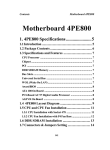
FN95
Socket 939
AMD TM Athlon 64 Processor
Based DDR Main Board
User's Manual
Shuttle® FN95
Socket 939
AMD AthlonTM 64 Processor
Based DDR Mainboard
Manual Version 1.0
Copyright
Copyright© 2004 by Shuttle® Inc. All Rights Reserved.
No part of this publication may be reproduced, transcribed, stored in a retrieval system,
translated into any language, or transmitted in any form or by any means, electronic,
mechanical, magnetic, optical, chemical, photocopying, manual, or otherwise, without
prior written permission from Shuttle® Inc.
Disclaimer
Shuttle® Inc. shall not be liable for any incidental or consequential damages resulting from the
performance or use of this product.
This company makes no representations or warranties regarding the contents of this manual.
Information in this manual has been carefully checked for reliability; however, no guarantee is
given as to the correctness of the contents. In the interest of continued product improvement,
this company reserves the right to revise the manual or include changes in the specifications
of the product described within it at any time without notice and without obligation to notify any
person of such revision or changes. The information contained in this manual is provided for
general use by the customers.
Trademarks
Shuttle is a registered trademark of Shuttle Inc.
AMD AthlonTM 64 is registered trademarks of AMD Corporation.
nVIDIA is a registered trademark of nVIDIA Corporation.
PS/2 is a registered trademark of IBM Corporation.
AWARD is a registered trademark of Award Software Inc.
Microsoft and Windows are registered trademarks of Microsoft Corporation.
General Notice: Other brand and product names used herein are for identification
purposes only and may be trademarks of their respective owners.
M940
Statement of Shuttle Mainboard via the EMI Test
Shuttle mainboards have been via the EMI test in terms of series of regulations: EN55022/
CISPR22/AS/NZS3548 Class B, EN55024 (1998/AS/NZS), EN4252.1 (1994), EN61000, ANSI
C63.4 (1992), CFR47 Part 15 Subpart B, and CNS13438 (1997). The items tested are illustrated as follows:
(A) Voltage: AC 110V/60HZ & AC 230V/50HZ
(B) Tested Product Information:
Product Name: PC Mainboard
Status: Sample
Model Name: FN95
S/N: N/A
CPU:
External Frequency: 200 MHz
AMD AthlonTM 64 : 2900+, 3200+
Serial Port: one port with 9 pins
Keyboard Port: one port with 6 pins
Mouse Port: one port with 6 pins
USB 2.0 Port: four ports with 4 pins respectively
Parallel Port: one port with 25 pins
1394 Port: one port with 4 pins respectively
1394 Port: one port with 6 pins respectively
LAN Port: one port with 8 pins (10Mbps/100Mbps/1000Mbps)
Mic-In & Line-In & Earphone Ports: one port for each
Coaxial Output Port: one port
SPDIF In Port: one port
DIMM Memory (optional): Kingston 256 MB *2
Power Cable: Detachable and Shielded (with a GND pin)
Monitor: CRT
Maximum Resolution: 1280 X 1024 V:60Hz
All CPUs have completely been tested, and values offered by the worst EMI combination of
CPU external frequency are listed as follows:
Test Mode
1
External Frequency
CPU
200MHz
Athlon XP 3200+
(C) Remedy for the Tested Product & Its EMI Interference:
Remedy: N/A
EMI Interference:
Crystal : 32.768 KHz(X2)/ 25 MHz(Y1)/ 25 MHz(X1)/ 24.576 MHz(X3)/ 24.576
MHz(X6)
(D) Supported Host Peripherals:
Host Peripheral
Product Name
Model Name
#1
Case
FN95
#2
Power Supply (240W)
PC35I2402
#3
Western Digitel HDD
(30 GB)
WD300BB
#4
MITSUMI FDD
D353M3D
#5
Panasonic DVD
Player
DVD-115
S/N
FCC ID
3902B934
62007003
3892A807
(E) Notices for Assembling Computers:
1. Cases should be made of iron or other metal that has good electric conductivity.
2. Cylinders in a case should be made of metal, and as having a mainboard mounted
in a case, make sure screws are all utilized and fastened on a mainboard.
3. An I/O shielding should be contacted with I/O metallic parts of a mainboard.
4. Cables should appropriately be arranged and fixed in a case. Follow instructions:
Ø Leave IDE cables not crossed upon CPU and SDRAM;
Ø Leave power cables minimum in length, and not crossed upon a mainboard;
Ø Leave CPU fan cables minimum in length, and not near CPU;
Ø Leave cables on panels and other spare cables tied in a computer case.
5. Make sure an EMI shielding attached to a case has properly been installed.
6. Make sure a 5.25" or 3.5" FDD and screws are fastened to an EMI shielding.
7. Make sure a case is closely in contact with EMI connected points.
8. Make sure there is no cleft in a case which is not deformed.
9. Make sure a PCI or AGP door is bound to a case.
10. Make sure cables of other devices (fans or some others) are fixed in a case.
TABLE OF CONTENTS
WHAT'S IN THE MANUAL .................................................................... 5
Quick Reference ............................................................................................... 5
About This Manual ........................................................................................... 5
1 INTRODUCTION ................................................................................ 6
1.1 TO DIFFERENT USERS ............................................................................. 6
FIRST-TIME DIY SYSTEM BUILDER............................................................ 6
EXPERIENCED DIY USER ........................................................................ 6
SYSTEM INTEGRATOR............................................................................... 6
1.2 ITEM CHECKLIST ....................................................................................... 7
2 FEATURES ........................................................................................ 8
2.1 SPECIFICATIONS ....................................................................................... 8
3 HARDWARE INSTALLATION .......................................................... 11
3.1 STEP BY STEP INSTALLATION ................................................................ 11
Accessories of FN95 ............................................................................. 11
STEP 1 Install the CPU .......................................................................... 12
STEP 2 Set Jumper ............................................................................... 13
STEP 3 Install DDR SDRAM System Memory........................................ 13
STEP 4 Install Peripherals in System Case ............................................ 14
STEP 5 Mount the Mainboard on the Computer Chassis ........................ 15
STEP 6 Connect Front Panel Header, Front Panel AUDIO/ USB/ 1394
Connector(JP16) ................................................................................... 16
STEP 7 Connect IDE, Floppy and Serial ATA Drives .............................. 17
STEP 8 Connect Other Internal Peripherals ............................................ 18
STEP 9 Install Add-on Cards in Expansion Slots .................................... 20
STEP 10 Connect the Power Supply Connectors ................................... 20
STEP 11 Connect External Peripherals to Back Panel ........................... 21
STEP 12 First Time System Boot Up ..................................................... 22
-1-
STEP 13 Install Drivers & Software Components ................................... 23
3.2 JUMPER SETTINGS ................................................................................. 24
JUMPERS & CONNECTORS GUIDE .................................................... 25
Jumper
Clear CMOS Setting (JP17) ................................................................. 27
Back-Panel Connectors
COM1 Port Connector ........................................................................... 28
SPDIF-IN Connector .............................................................................. 28
1394 Port Connector ............................................................................. 28
PS/2 Mouse & PS/2 Keyboard Port Connectors .................................... 28
LAN Port Connector .............................................................................. 28
USB Port Connectors ............................................................................ 28
Coaxial Output Port Connector............................................................... 29
Line-In Port Connector ........................................................................... 29
Center/Bass-Out Port Connector ........................................................... 29
Rear-Out Port Connector ....................................................................... 29
Front-Out Port Connector ....................................................................... 29
Clear CMOS Button (SW1) .................................................................... 29
Front-Panel Connectors
ATX Power On/Off Switch Connector (PWON) ....................................... 30
HDD LED Connector (HLED) ................................................................ 30
Green LED/ Power LED Connector (GLED/PWR_LED) ........................ 31
Hardware Reset Connector (RST) ......................................................... 31
Front Panel AUDIO/ USB/ 1394 Connector (JP16) ................................. 32
Internal Peripherals Connectors
Enhanced IDE and Floppy Connectors................................................... 33
Serial ATA Connectors (ATA1/ATA2) ...................................................... 33
-2-
Other Connectors
ATX Power Supply Connectors (ATX1/CN5) .......................................... 34
Fan Connectors - FAN1/2/3 OFF when suspend .................................... 35
Wireless Keyboard/Mouse Connector (JP2) .......................................... 36
CD-IN Connector (CN7) (Black) ............................................................. 36
LINE_IN Connector (CN8) (White) .......................................................... 36
Mini CD_IN Connector (CN6) (White) .................................................... 36
Dual USB Header(JP3)/ USB Connectors(USB2, USB3)....................... 37
IrDA Header (JP5) ................................................................................. 37
SPDIF out Connector (CN4) .................................................................. 38
Printer Port Connector (J1) .................................................................... 38
3.3 SYSTEM MEMORY CONFIGURATION ..................................................... 39
4 SOFTWARE UTILITY ...................................................................... 40
4.1 Mainboard CD Overview ......................................................................... 40
4.2 Install Mainboard Software ...................................................................... 40
4.2.A Install DirectX9 Utility ............................................................................ 41
4.2.B Install nVIDIA Chipset Driver ................................................................ 41
4.2.C Install Marvell Giga LAN Driver............................................................. 42
4.2.D Install nVIDIA USB 2.0 Driver ................................................................ 42
4.3 View the User's Manual ............................................................................ 43
5 BIOS SETUP ................................................................................... 44
5.1 ENTER BIOS ............................................................................................. 44
5.2 THE MAIN MENU ...................................................................................... 45
STANDARD CMOS FEATURES ............................................................... 47
ADVANCED BIOS FEATURES ................................................................. 50
ADVANCED CHIPSET FEATURES .......................................................... 54
-3-
INTEGRATED PERIPHERALS .................................................................. 57
POWER MANAGEMENT SETUP .............................................................. 60
PNP/PCI CONFIGURATION....................................................................... 63
PC HEALTH STATUS ................................................................................ 65
RATIO/VOLTAGE CONTROL ..................................................................... 67
LOAD FAIL-SAFE DEFAULTS................................................................... 68
LOAD OPTIMIZED DEFAULTS .................................................................. 68
SET PASSWORD ..................................................................................... 68
SAVE & EXIT SETUP ................................................................................ 69
EXIT WITHOUT SAVING ............................................................................ 69
-4-
WHAT'S IN THE MANUAL
Quick Reference
Hardware Installation >> Step-by-Step ................................................ Page 11
Jumper Settings >> A Closer Look ....................................................... Page 24
Drivers/Software Utilities >> How to Install ......................................... Page 40
BIOS Setup >> How to Configure ......................................................... Page 44
About This Manual
For First-Time DIY System Builder ......................................................... Page 6
For Experienced DIY User ...................................................................... Page 6
For System Integrator ............................................................................. Page 6
-5-
1 INTRODUCTION
1.1 To Different Users
First-Time DIY System Builder
Welcome to the DIY world! Building your own computer system is not as difficult as you may think. To make your first computer DIY experience successful,
right from the start, we have designed the 3.1 Hardware Installation section
in a step-by-step fashion for all the first-time DIY system builders. Prior to installation, we also suggest you to read the whole manual carefully to gain a complete understanding of your new Shuttle FN95 mainboard.
Experienced DIY User
Congratulate on your purchase of the Shuttle FN95 mainboard. You will find
that installing your new Shuttle FN95 mainboard is just easy. Bundled with an
array of onboard functions, the highly-integrated FN95 mainboard provides
you with a total solution to build the most stable and reliable system. Refer to
sections 3.2 Jumper Settings and Chapter 4 Drivers/Software Utilities to
find out how to get the best out of your new mainboard. Chapter 5 BIOS
Setup also contains the relevant information on how to tune up your system to
achieve higher performance.
System Integrator
You have wisely chosen Shuttle FN95 to construct your system. Shuttle FN95
incorporates all the state-of-the-art technology of the nVIDIA nForce3 250 Ultra
Single Chip for AMD TM Athlon64 939 CPU. It integrates the most advanced
functions you can find to date in a compact Shuttle Form Factor board.
-6-
1.2 Item Checklist
Check all items with you FN95 mainboard to make sure nothing is missing.
The complete package should include:
COM1
OPT2
CN3
KB1
USB1 LAN1
A UDIO2
A UDIO1
SW1
- One piece of Shuttle FN95 Mainboard
CN7
1
1
1
CN4
1
CN8
CN6
1
DIMM1 DIMM2
FAN1
J1
FLP1
1
AGP1
FAN2
ATA1
n VIDI A
P CI1
R
JP17
1
JP3
FAN3
USB
USB3 USB2
1
JP5 IR
S
Y
T
K BATTER
IUM STD
LITHJAPAN 032
CR2
1
CN5
1
1
JP12
1
1
IDE1
1
- One piece of ATA133/100/66/33 Ribbon Cable
1
JP2
1
IDE2
JP16
ATX1
- One piece of Serial ATA Cable
SERIAL
VSO
ATA
- FN95 User's Manual
- nVIDAI RAID User's Guide
- One piece of Bundled CD-ROM with containing:
Ø FN95 user's manual saved in PDF format
Ø nVIDIA RAID User's Guide saved in PDF format
Ø Install DirectX9 Utility
Ø Install nVIDIA Chipset Driver
Ø Install Marvell Giga LAN Driver
Ø Install nVIDIA USB 2.0 Driver
Ø Award Flashing Utility
-7-
2 FEATURES
FN95 mainboard is carefully designed for the demanding PC user who wants high performance and maximum intelligent features in a compact package.
2.1 Specifications
- CPU Support
AMD TM Athlon64 with 200MHz FSB colock on 939-pins SMT Socket.
- Chipset
nVIDIA nForce3 250 Ultra Single Chip for AMD TM Athlon64 939 CPU.
Gigabit ETHERNET Controller
Marvell 8001, support 10/100 /1000 Mbps operation rate. Supports Wakeon-Lan (WOL) function.
Onboard 1394
VIA VT6307, support 400Mb/s, 200Mb/s, or100Mb/s data transfer rate.
Compliants with 1394 OHCI specification revision V1.0 and V1.1 and
provides 2 fully compliant ports.
Onboard SATA
Integrated SATA, support 2 Serial-ATA connectors (devices) with Raid 0/ 1/
0+1/JBOD function. SATA Host controller spports Generation 1.5 Gb/s per
channel for total of 3.0 Gb/s in each direction.
- Jumperless CPU Configuration
Soft-configuration FSB (The FSB speed is software configurable from 200MHz
to 280MHz in the Advenced Chipset Features of BIOS setup program.)
- On Board 5.1 Channel AC97 Audio
Compliant with AC'97 2.2 specifications.
5.1 channel slot selectable DAC Output for multi-channel applications.
- Versatile Memory Support
128-bit DDR SDRAM at 100/133/166/200 supports up to 2 GB.
- AGP Expansion Slot
Provides one 32-bit AGP slot which support 4X, 8X AGP device.
- PCI Expansion Slots
Provides one 32-bit PCI slot.
- 8 USB 1.1/2.0 Complaint Interface Onboard
-8-
Ø 2 x USB connectors on back-panel, one set of dual USB port header on midboard.
- I/O Interface
Provides a variety of I/O interfaces:
Ø 1 Floppy interface for 3.5-inch FDD with 720KB, 1.44MB, or 2.88MB
format or for 5.25-inch FDD with 360K or 1.2MB format.
Ø 1 COM1 Port.
Ø 1 SPDIF IN Port.
Ø 1 1394 Port.
Ø 1 PS/2 Keyboard Port.
Ø 1 PS/2 Mouse Port.
Ø 1 10/100/1000 LAN Port.
Ø 2 USB 1.1/2.0 Ports.
Ø 1 Coaxial Port.
Ø 1 Line-InPort.
Ø 1 Center/Bass-Out port.
Ø 1 Rear-Out port.
Ø 1 Front-Out port.
- PCI Bus Master IDE Controller Onboard
Two Ultra DMA 133 Bus Master Dual-channel IDE ports provide support to a
maximum of four IDE devices (one Master and one Slave per channel). The IDE
Bus implements data transfer speeds of up to 133/100/66/33 MB/sec and
also supports Enhanced PIO Modes.
80-pin Cable Backward Compatible Legacy ATAPI Devices, ATAPI IDE CDROM, CD-R, CD-RW, and LS-120 Supports.
- ATX Power Supply Connector
ATX power supply unit can connected to the onboard 20-pin standard ATX
power connectors, supporting Suspend and Soft-On/Off by dual-function power
button. One 4-pin 12V ATX power connector.
- Advanced Configuration and Power Interface
Features four power saving modes: S1 (Snoop), S3 (Suspend to RAM), S4 (Suspend to DISK), and S5 (Soft-Off). ACPI provides more efficient Energy Saving
Features controlled by your operating system that supports OS Direct Power
Management (OSPM) functionality.
-9-
- System BIOS
Provides licensed Award BIOS V6.0 PG on 4Mb Flash core and supports Green
PC, Desktop Management Interface (DMI).
- Form Factor
System board conforms to Small form factor ATX specification.
Board dimension: 254mm X185mm.
- Advanced Features
Ø Low EMI - Built in spread spectrum and automatic clock shut-off of unused
PCI/SDRAMS slots to reduce EMI.
Ø Dual Function Power Button - The system can be in one of two states,
one is Suspend mode and the other is Soft-Off mode. Pushing the power
button for less than 4 seconds places the system into Suspend mode. When
the power button is pressed for longer than 4 seconds, the system enters SoftOff mode.
Ø Wake-on-LAN (WOL) - The onboard WOL connector can be attached to
a network card that supports this function to wake up the system via LAN.
Ø Modem Ring Power-On - The system can be powered on automatically
by the activation of modem ringing.
Ø CPU Host/SDRAM - This item allows users to adjust CPU Host Clock,and
SDRAM in BIOS.
- Intelligent Features
Ø Voltage Monitoring - Monitors various voltages of key elements, such as
the CPU, and other critical system voltage levels to ensure stable current
passing through mainboard components.
Ø Fan Status Monitoring - To prevent CPU from overheating, the CPU fan
is monitored for RPM and failure. (CPU Cooling FAN with RPM sensor is
required.)
Ø Temperature Monitoring - This item allows users to make sure whether
the CPU or system runs in a suitable temperature.
- 10 -
3 HARDWARE INSTALLATION
Before removing or installing any of these devices including CPU, DIMMs,
Add-On Cards, Cables, please make sure to unplug the onboard power
connector.
This section outlines how to install and configure your mainboard. Refer to the following
mainboard layout to help you to identify various jumpers, connectors, slots, and ports.
Then follow these steps designed to guide you through a quick and correct installation of
your system.
3.1 Step-by-Step Installation
Accessories Of FN95
10/100/1000LAN &
1.1/2.0 USB 2.0 Connectors
PS/2 Keyboard/Mouse Connectors
Coaxial/Line-In Connectors
CD-IN Connector-CN7
Center/Bass/Rear-Out/Front-Out Connectors
Clear CMOS Button-SW1
SPDIF out Connector-CN4
LINE_IN Connector-CN8
SPDIF-IN Connector
COM Connector
COM1
OPT2
CN3
KB1
USB1 LAN1
AUDIO2
Mini CD-IN Connector-CN6
AUDIO1
SW1
FAN1
CN7
1
CN4
1
Printer Port Connector-J1
CN8
CN6
One PCI Slot
1
DIMM1 DIMM2
FAN1
J1
FLP1
1
AGP1
SOCKET 939
FAN2
ATX +12V Power Connector-CN5
ATX Power Connector-ATX1
PCI1
ATA1
Serial ATA Connectors
-ATA1/ATA2
One AGP Slot
n VIDIA
nVIDIA nForce3 250
Chipset
USB Connectors-USB2/3
R
Clear CMOS-JP17
JP17
FAN3
1
JP3
FAN3
USB
USB3 USB2
1
JP5 IR
1
CN5
1
JP12
1
1
IDE1
1
JP2
1
Front Panel Header-JP12
S RY
T
E
K BATT
IUM STD
LITH JAPAN 032
2
CR
1
Dual USB Header-JP3
IrDA Header-JP5
FAN2
Two 184-pin DDRSDRAM
DIMM Slots
One Floppy Connector-FLP1
1
1
1
IDE2
JP16
ATX1
Two IDE Connectors-IDE1/IDE2
Wireless KB/MS Connector- JP2
Front Panel AUDIO/USB/1394 Connector- JP16
- 11 -
Step 1
Install the CPU:
1. Locate the CPU ZIF (Zero Insertion Force) socket on the upper-right sector of
your mainboard (between the back-panel connectors and the DIMM memory
slots).
2. Pull the CPU ZIF socket lever slightly sideways away from the socket to
unlock the lever, and then bring it to an upwardly vertical position.
3. Place your AMD AthlonTM 64 processor in the socket 939 CPU. Note that
the CPU's edges have been purposely designed non-symmetrically to prevent from in serting the processor in the wrong direction. The following diagram demon strates the correct placement of the CPU in the ZIF socket. You
can see that the Triangle Mark.
A Triangle
Mark
A Triangle
Mark
AMD CPU
Lever
Lever
4. Slightly push the AMD Athlon 64 processor into the socket without applying exces sive force while making sure there is no gap between CPU and
socket. Then lower the socket-lever all the way down to its horizontal position and lock it to secure the CPU in place.
TM
5. The AMD AthlonTM 64 processor requires a set of heatsink/fan to ensure
proper cooling of the processor. If heatsink/fan have not been already
mounted on your CPU, you must purchase the heatsink/fan sepa-rately and
have it installed. Plug the cable throught the heatsink/fan in the CPU fan
power connector located nearby. Note that there are several types of CPU
fan connectors. Normally, if your mainboard supports the hardware monitoring function, a 3-pin fan power connector should allow your system to
detect the CPU fan's speed. The CPU fan can also run with a 2-pin fan
power connector, however, detection of CPU fan's speed is not supported.
Another type of CPU fan may feature a large 4-pin fan power connector,
which does not support CPU fan's speed detection and must be directly
connected to the system's power supply unit. Please refer to the following
diagram.
- 12 -
Step 2
Set Jumper
This mainboard is jumperless! The default jumper settings have been set for the
common usage standard of this mainboard. Therefore, you do not need to reset
the jumpers unless you require special adjustments as any of the following cases:
1. Clear CMOS
For first-time DIY system builders, we recommend that you do not change the
default jumper settings if you are not totally familiar with the mainboard configuration procedures. The factory-set default settings are tuned for optimum
system performance. For the advanced users who wish to customize their system, section 3.2 Jumper Settings will provide detailed information on how to
configure your mainboard manually.
Step 3
Install DDR SDRAM System Memory
To install memory, insert DDR SDRAM memory module(s) in DIMM slot(s).
Note that DDR SDRAM modules are directional and will not go in the DIMM
slots unless properly oriented. After the module is fully inserted into the DIMM
slots, lift the clips of both sides of the DIMM slot to lock the module in place.
Do not remove memory modules while DIMM LED is on. It might cause short
or other unexpected damages due to the 2.5V stand by voltage. Remove memory
modules only when AC Power cord is disconnected.
DDR SDRAM
DIMM Power LED
DIMM
Power
LED
(Green)
- 13 -
Step 4
Install Internal Peripherals in System Case
Before you install and connect the mainboard into your system case, we
recommend that you first assemble all the internal peripheral devices into the
computer housing, including but not limited to the hard disk drive (IDE/
HDD), floppy disk drive (FDD), CD-ROM drive, and ATX power supply unit.
This will greatly facilitate in making the connections to the mainboard described below.
To install IDE & FDD drives, follow this procedure:
1. Set the required jumpers on each device according to the instructions
provided by the manufacturer. (IDE devices, HDD, and CD-ROM, have to
set jumpers to Master or Slave mode depending on whether you install
more than one device of each kind.)
2. Connect IDE cable and FDD cable on the back-panel of the internal
peripheral devices to the corresponding headers on board. Note that the
cable should be oriented with its colored stripe (usually red or magenta)
connected to pin#1 both on the mainboard IDE or FDD connector and on
the device as well.
3. Connect an available power cable from your system power supply unit
to the back-panel of each peripheral device. Note that the power cable is
directional and cannot fit in if not properly positioned.
- 14 -
Step 5
Mount the Mainboard on the Computer Chassis
1. You may find that there are a lot of different mounting hole positions both on
your computer chassis and on the mainboard. To choose correct mounting
holes, the key point is to keep the back-panel of the mainboard in a close fit
with your system case, as shown below.
2. After deciding on the proper mounting holes, position the studs between the
frame of the chassis and the mainboard.
The studs are used to fix the mainboard and to keep a certain distance between the system chassis and the mainboard, in order to avoid any electrical
shorts between the board and the metal frame of the chassis. (If your computer case is already equipped with mounting studs, you will need to tighten
screws to attach the mainboard.)
Note : In most computer housings, you will be able to find 4 or more attachment points to install mounting studs and then fix the mainboard.
If there aren enough matching holes, then make sure to install at
least 4 mounting studs to ensure proper attachment of the mainboard.
- 15 -
Step 6
Connect Front Panel Header
You can find there are several different cables already existing in the system
case and originatinting from the computer's front-panel devices (HDD LED,
Power LED,or Reset Switch devices etc.) These cables serve to connect the
front-panel switches and LEDs connectors to the mainboard's front-panel connectors group, as shown below.
JP12
- +
- +
1
- +
2 HLED
RST HLED
- +
+ - - +
1.
2.
3.
4.
GLED 3
PWON GLED/PLED
4 RST
PWON 1
PLED
Front Panel
1
JP12
ATX Soft Power On/Off (POWER ON)
HDD-LED (HDD LED)
Green-LED and Power-LED (GREEN LED/POWER LED)
Hardware Reset Switch Button (RESET)
Connect Front Panel AUDIO/ USB/ 1394 Connector(JP16)
You can find there are several different
cables already existing in the system case
and originatinting from the computer's
front-panel devices (AUDIO, USB, 1394a
devices etc.). These cables serve to
connect the AUDIO, USB, 1394a,
connectors to the mainboard's front panel
connectors group, as shown below.
2
50
1
49
Front Panel
JP16
- 16 -
Step 7
Connect IDE, Floppy and Serial ATA Drives
1. IDE cable connectors
1
1
IDE1
IDE2
FLP1
2. Floppy cable connector
1
3. Serial ATA connectors
ATA2 ATA1
- 17 -
Step 8
Connect Other Internal Peripherals
1. Wireless KB/MS Header (JP2)
Wireless KB/MS
1
JP2
2. CD-IN(CN7), LINE-IN(CN8), MINI CD-IN(CN6) Connectors
CD-IN CN7
1
Mini CD-IN
LINE-IN CN8
1
CN6
1
3. IrDA Header (JP5)
IrDA Header
1
JP5
- 18 -
4. DUAL USB Header (JP3)
USB Connectors (USB2/USB3)
JP3
1
1
1
USB3 USB2
5. SPDIF out Connector (CN4)
CN4
1
6. Printer Port Connector (J1)
J1
1
- 19 -
Step 9
Install Add-on Cards in Expansion Slots
1. Accelerated Graphics Port (AGP) Card
AGP proof LED: Serving as a smart burnout protection for the motherboard, this
red LED lights up if you plug in any 3.3V
AGP card into the AGP slot. When this
LED is Lit, there is no way you can turn
on the system power even if you press
the power button. The red LED(AGP
proof) is a smart protection from
motherboard burn out caused by an incorrect AGP card. If you plug in any
3.3V AGP card into the 1.5V AGP slot,
this LED lights up thus preventing the
system to power up. This LED remains
off if you plug in a 1.5V AGP card.
AGP Proof
LED (Red)
2. PCI Card
Step 10
Connect the Power Supply Connectors
1. System power connectors (ATX1/CN5)
ATX12V
1
CN5
1
ATX1
- 20 -
ATXPWR
Step 11
Connect External Peripherals to Back-Panel
You are now ready to put the computer case back together and get on to the
external peripherals connections to your system's back-panel.
1.
2.
3.
4.
5.
6.
7.
8.
9.
10.
11.
12.
13.
COM Port
SPDIF out Connector
1394 Port
PS/2 Mouse Port
PS/2 Keyboard Port
10/100/100 LAN Port
USB 1.0/2.0 Port
Coaxial Output Port
Line-In Port
5-1 Channel Center/Bass Port
5-1 Channel Rear-Out Port
5-1 Channel Front-Out Port
Clear CMOS Button
1
2
3
4
6
8
10
11
5
7
9
12
13
- 21 -
Step 12
First Time System Boot Up
To assure the completeness and correctness of your system installation, you
may check the above installation steps once again before you boot up your
system for the first time.
1. Insert a bootable system floppy disk (DOS 6.2x, Windows 95/98/NT, or
others) which contains FDISK and FORMAT utilities into the FDD.
2. Turn on the system power.
3. First, you must use the FDISK utility to create a primary partition of the
hard disk. You can also add an extended partition if your primary partition does not use all of the available hard disk space. If you choose to
add an extended partition, you will have to create one or more logical
partitions to occupy all the space available to the extended partition. The
FDISK utility will assign a drive letter (i.e., C:, D:, E:,...) to each partition
which will be shown in the FDISK program. After FDISK procedure, reboot
your system by using the same system floppy disk.
Note: DOS 6.2x and Windows 95A can only support up to 2.1GB of
HDD partition. If you use the FDISK utility with one of the operating systems mentioned above, you can only install your HDD into
partitions no larger than 2.1GB each.
4. Now, use the FORMAT utility to format all the partitions you've created.
When formatting the primary partition (C:), make sure to use the FORMAT C: /S command.
Note: FORMAT C: /S can transfer all the necessary system files into the
primary partition of your hard disk. Then, your HDD will become
a bootable drive.
5. Install all the necessary drivers for CD-ROM, Mouse, etc.
6. Setup the complete operating system according to your OS installation
guide.
- 22 -
Step 13
Install Drivers & Software Components
Please note that all the system utilities and drivers are designed for Win 9x/
2000/ME/XP/NT operating systems only. Make sure your operating system is
already installed before running the drivers installation CD-ROM programs.
1. Insert the FN95 bundled CD-ROM into your CD-ROM drive.
The autorun program will display the drivers main installation window on
screen.
2. Choose "Install DirectX9 Utility" and complete it.
3. Choose "Install nVIDIA Chipset Driver" and complete it.
4. Choose "Install Marvell Giga LAN Driver" and complete it.
5. Choose "Install nVIDIA USB 2.0 Driver" and complete it.
6. Exit from the autorun drivers installation program.
] Please refer to section Chapter 4 Software Utility to install driver.
- 23 -
3.2 Jumper Settings
Several hardware settings are made through the use of mini jumpers to connect
jumper pins on the mainboard. Pin #1 could be located at any corner of each
jumper, you just find the location with a white right angle which stands for pin
1#. There are several types of pin 1# shown as below:
3-pin and multi (>3) pin jumpers shown as following:
Pin #1 to the left:
Pin #1 on the top:
Pin #1 to the right:
Pin #1 on the bottom:
Jumpers with two pins are shown as
for Close [On] or
for
Open [Off]. To Short jumper pins, simply place a plastic mini jumpers over
the desired pair of pins.
Caution!
1. Do not remove the mainboard from its antistatic protective packaging
until you are ready to install it.
2. Carefully hold the mainboard by its edges and avoid touching its components. When putting the mainboard down, place it on top of its original packaging film, on an even surface, and components side up.
3. Wear an antistatic wrist strap or take other suitable measures to prevent
electrostatic discharge (ESD) whenever handling this equipment.
- 24 -
Jumpers & Connectors Guide
Use the mainboard layout on page 11 to locate CPU socket, memory banks,
expansion slots, jumpers and connectors on the mainboard during the installation. The following list will help you to identify jumpers, slots, and connectors along with their assigned functions:
B13 B10~B12 E5
B8~B9 B6~B7 B4~B5 B3 B2
B1
E9
E6
E6
E4
D1
E2
E2
D2
E7
A1
E2
E7
E8
E1
C1~C4
D1
C5
E3
CPU/Memory/Expansion Slots
Socket 939
: CPU Socket for AMD AthlonTM 64
DIMM1/2
: Two184-pin DIMM Slots for 64, 128, 256, 512 MB,
and 1GB of 2.6V DDR SDRAM
(The total installed memory does not exceed 2GB)
PCI
: One 32-bit PCI Expansion Slot
AGP
: One AGP Slot 4X/8X Slot
- 25 -
Jumper
JP17
A1
B1
B2
B3
B4
B5
B6
B7
B8
B9
B10
B11
B12
B13
C1
C2
C3
C4
C5
D1
D1
D1
D2
E1
E2
E3
E4
E5
: Clear CMOS setting
Back Panel Connectors
COM1
: Serial port
SPDIF IN
: SPDIF IN Port
1394
: 1394 Port
MS
: PS/2 mouse port
KB
: PS/2 keyboard port
LAN
: 10/100/1000 LAN port
USB
: 2 X USB (2.0/1.1) (Universal Serial Bus) ports
Coaxial
: Coaxial Output port
Line-In
: Line-In port
CENTER/BASS : 5-1 Channel Center/Bass Port
Rear-Out
: 5-1 Channel Rear-Out Port
Front-Out
: 5-1 Channel Front-Out Port
SW1
: Clear CMOS Button
Front Panel Connectors
PWON
: ATX power on/off momentary type switch
HLED
: IDE drive active LED
GLED/PWR_LED : Green LED (ON when system stays in power
saving mode) /System power LED
RST
: Hardware reset switch
JP16
: Front Panel AUDIO/ USB/ 1394 Connector
Internal Peripherals Connectors
FLP1
: Floppy disk drive interface
IDE1
: IDE primary interface (Dual-channel)
IDE2
: IDE secondary interface (Dual-channel)
ATA1/2
: Serial ATA 1/2 interfaces
Other Connectors
CN5/ATX1
: ATX power connectors
FAN1, 2, 3
: Fan connectors
JP2
: Wireless Keyboard and Mouse connector
CN8
: Line_In connector
CN7
: CD-IN connector
- 26 -
CN6
JP3/USB2/USB3
JP5
CN4
J1
E6
E7
E8
E9
E10
F
: MINI CD-IN connector
: DUAL USB Header/ USB Connectors
: IrDA Header
: SPDIF Out Connector
: Printer Port Connector
Jumper
A1
Clear CMOS Setting (JP17)
JP17 is used to clear CMOS data. Clearing CMOS will result in the permanently erasing previous system configuration settings and the restoring original (factory-set) system settings.
1
Pin 1-2 (Default)
1
Pin 2-3 (Clear CMOS)
Clear CMOS
1
JP17
Step 1. Turn off the system power (PC-> Off).
Step 2. Remove ATX Power cable from ATX Power connector.
Step 3. Remove jumper cap from JP11 pins 1-2.
Step 4. Place the jumper cap on JP11 pin 2-3 for a few seconds.
Step 5. Return the jumper cap to pin 1-2.
Step 6. Plug ATX Power cable into ATX Power connector.
Step 7. Turn on the system power (PC-> On).
- 27 -
F
Back-Panel Connectors
B1
COM1 Port Connector
This mainboard can accommodate one
serial device on COM1. Attach a serial
device cable to the DB9 serial port
COM1 at the back-panel of your computer.
B2
SPDIF-IN Connector
SPDIF IN connector can accept
digital audio data from Optic fiber.
B3
1394 Port Connector
This mainboard offers one 1394a ports
on back-panel. Plug each device jack
into an available 1394a connector.
B4 B5
5
B6
SPDIF-IN Port
1394 Port
PS/2 Mouse & PS/2 Keyboard Port Connectors
Two 6-pin female PS/2 Mouse & Key
board connectors are located on the
rear panel of the mainboard. In a
desktop computer, the PS/2 Mouse
connector is situated on the top of
the PS/2 Keyboard connector. In a
tower computer, the PS/2 Mouse
connector is located on the rightside
of the PS/2 Keyboard connector.
LAN Port Connector
This mainboard can accommodate
one device on LAN.
Attach a RJ45 cable to the LAN port at
the back-panel of your computer.
B7
COM1 Port
USB Port Connectors
Two female connectors USB1/USB2
share the same USB (Universal Serial
Bus) bracket at the rear panel of your
mainboard. Plug each USB device jack
into an available USB1/USB2 connector.
- 28 -
PS/2 Mouse Connector
PS/2 Keyboard connector
LAN Port
USB Ports
B8
Coaxial Output Port Connector
Coaxial Output Port
Coaxial Output connector can output digital audio data from coaxial
cable.
B9
Line-In Port Connector
Line-In is a stereo line-level input
port that accepts a 1/8-inch TRS stereo plug. It can be used as a source
for digital sound recording, a source
to be mixed with the output, or both.
B10
Center/Bass-Out Port Connector
Center/Bass-Out is a stereo output
port through which the combined
signal of all internal and external
audio sources on the board is output. It can be connected to 1/8-inch
TRS stereo headphones or to center/
bass amplified speakers.
B11
Rear-Out Port
Front-Out Port Connector
Front-Out is a stereo output port
through which the combined signal of
all internal and external audio sources
on the board is output. It can be connected to 1/8-inch TRS stereo headphones or to amplified speakers.
B13
Center/Bass-Out Port
Rear-Out Port Connector
Rear-Out is a stereo line-level input port
that accepts a 1/8-inch TRS stereo plug.
It can be used as a source for digital
sound recording, and a source to be
mixed with the output, or both.
B12
Line-In Port
Front-Out Port
Clear CMOS Button (SW1)
This button is used to Clear CMOS
data. You can clear CMOS without
opening the chassis. It's very friendly
button.
- 29 -
Clear CMOS Button
F
Front-Panel Connectors
C1
ATX Power On/Off Switch Connector (PWON)
The Power On/Off Switch is a momentary type switch used for turning on or off
the system ATX power supply. Attach the connector cable from the Power Switch
to the 2-pin (PWON) header on the mainboard.
Front Panel
RST
HLED
PWON GLED/PLED
1
JP12
Note : Please notice all the LED connectors are directional. If your chassis’s
LED does not light up during running, please simply change to the
opposite direction.
C2
HDD LED Connector (HLED)
Attach the connector cable from the IDE device LED to the 2-pin (HDD LED)
header. The HDD LED lights up whenever an IDE device is active.
Front Panel
RST
- +
HLED
PWON GLED/PLED
- 30 -
1
JP12
C3
Green LED/ Power LED Connector (GLED/PWR_LED)
This header is dual color LED function. Dual color LED function is defined by
either Power LED or Green LED, the header can be in these states.
The Green LED indicates that the system is currently in one of the power saving
mode (Doze/Standby/Suspend). When the system resumes to normal operation mode, the Green LED will go off, power LED on.
This Power LED will go off during power saving mode. Attach a 2-pin Green
LED/Power LED cable to (GLED/PWR_LED) header.
- +
GLED
- +
2 4
HLED
PLED
+ -
RST
- +
C4
PWON GLED/PLED
2 4
Front Panel
1
JP12
Hardware Reset Connector (RST)
Attach the 2-pin hardware reset switch cable to the (RST) header.
Pressing the reset switch causes the system to restart.
Front Panel
RST
HLED
PWON GLED/PLED
- 31 -
1
JP12
Front Panel AUDIO/ USB/ 1394 Connector (JP16)
C5
Port JP16 can be used to connect special device.
2
50
1
49
Front Panel
JP16
Pin Assignments:
1=USBVCC
4=USBVCC
7=USBVCC
10=USBA13=USBB+
16=GND
19=GND
22=TPB125=Front MIC
28=GND
31=Line_IN_R
34=GND
37=GND
40=Front_OUT_L
43=HDLED_PU
46=GLEDB
49=VCC
2=USBVCC
5=USBVCC
8=USBVCC
11=GND
14=USBB17=TPA1+
20=GND
23=GND
26=FMIC_Power
29=Line_IN_L
32=SENSE1
35=Line_OUT_R
38=GND
41=GND
44=GLEDA
47=RST_SW
50=VCC
- 32 -
3=USBVCC
6=USBVCC
9=USBA+
12=GND
15=GND
18=TPA121=TPB1+
24=GND
27=SENSE0
30=GND
33=GND
36=Front_OUT_R
39=Line_OUT_L
42=GND
45=HD_LED
48=PW_SW
F
Internal Peripherals Connectors
D1
Enhanced IDE and Floppy Connectors
The mainboard features two 40-pin dual-channel IDE device connectors (IDE1/
IDE2) providing support for up to four IDE devices, such as CD-ROM and Hard
Disk Drives (H.D.D.). This mainboard also includes one 34-pin floppy disk controller (FDC) to accommodate the Floppy Disk Drive (FDD1). Moreover, this
mainboard comes with one 80-pin ATA 133/100/66/33 ribbon cable to connect to IDE H.D.D. and one 34-pin ribbon cable for F.D.D. connection.
FLP1
1
1
IDE1
IDE2
1
Important : Ribbon cables are directional, therefore, make sure to always
connect with the red cable stripe on the same side as pin #1 of
the IDE1/IDE2 or FDC connector on the mainboard.
D2
Serial ATA Connectors (ATA1/ATA2)
The Serial ATA is an evolutionary replacement for the Parallel ATA physical storage interface. Serial ATA is scalable and will allow future enhancements to the computing platform. The
Serial ATA supports all ATA and ATAPI
device, including CDs, DVDs, tape deATA2 ATA1
vices, high capacity removable devices, zip drivers, and CDRWs. The
Serial ATA interface supports data transfer rates up to 150MB/s.
- 33 -
F
Other Connectors
E1
ATX Power Supply Connectors (ATX1/CN5)
This motherboard uses 20-pin ATX power header (ATX1), and comes with the
other one header (CN5). Please make sure you plug each in the right direction.
It is essential to have these two power supply connectors plugged or your system won't boot up.
ATX1
CN5
ATX12V
1
CN5
1
ATX1
ATXPWR
A traditional ATX system remains in the power-off stage when AC power resumes from power failure. However, it is inconvenient for a network server or
workstation if there is not an UPS to execute power-on. Thus, this motherboard
supports an AC Power Auto Recovery function to solve this problem. You may
enable the function, "PWRON After PWR-Fail," in the sub-menu of "Power
Management Setup" within the BIOS setup program.
Note 1:
Note 2:
Note 3:
Note 4:
The ATX power connector is directional and will not go in
unless the guides match perfectly, making sure that pin#1 is
properly positioned.
Make sure the latch of the ATX power connector clicks into
place to ensure a solid attachment.
Your ATX power supply must be supplied to ACPI+5V standby power and at least 720mA compatible.
Make sure your power supply have enough power for higher
speed processor installed.
- 34 -
E2
Fan Connectors - FAN1/2/3 OFF when suspend
The mainboard provides three onboard 12V cooling fan power connectors
to support FAN1, FAN2 or FAN3 cooling fans.
FAN1
FAN_CTRL
FAN_SENSE
FAN2
POWER
1
Ground
FAN3
Note : Both cable wiring and type of plug may vary , which depends on the fan
maker. Keep in mind that the red wire should always be connected to
the +12V header and the black wire to the ground (GND) header.
E3
Wireless Keyboard and Mouse Connector (JP2)
Port JP2 can be used to connect wireless keyboard and mouse device.
4 mini Jumper must be setted on pin 5-6, 7-8, 9-10 and 11-12 when this
header is not used.
11 9
Pin Assignments:
1=VCC
2=VCC
3=GND
4=KEY
5=MS_CLK
6=MS_CLK_IC
7=MS_DAT
8=MS_DAT_IC
9=KB_CLK
7 5 3 1
12 10 8 6
4 2
10=KB_CLK_IC
11=KB_DAT 12=KB_DAT_IC
Wireless KB/MS
1
JP2
- 35 -
E4
CD-IN Connector (CN7) (Black)
Port CN7 is used to attach an audio connector cable from the CD-ROM drive.
CD-IN
1 2 3 4
CN7
1
Pin Assignments:
1=CD-IN Left
3=Ground
E5
CN7
2=Ground
4=CD-IN Right
LINE_IN Connector (CN8) (White)
Port CN8 (White) can be used to connect stereo audio inputs from CD-ROM,
TV-tuner or MPEG card.
CN8
1 2 3 4
LINE-IN CN8
1
Pin Assignments:
1=AUX-IN Left
3=Ground
E6
2=Ground
4=AUX-IN Right
Mini CD_IN Connector (CN6) (White)
Port CN6 is used to attach an audio connector cable from the CD-ROM drive.
1 2 3 4
Mini CD-IN
CN6
1
CN6
Pin Assignments:
1=Ground
2=CD-IN Right
3=Ground
4=CD-IN Left
- 36 -
E7
Dual USB Header(JP3)/ USB Connectors(USB2, USB3)
The headers are used to connect the cable attached to USB connectors which
are mounted on front panel or back panel. But the USB cable is optional at the
time of purchase.
USB2/3
JP3
1
2
3
4
5
E8
10
8
6
4
2
JP3
9
7
5
3
1
1
1
1
USB3 USB2
Pin Assignments (USB2/ USB3):
Pin Assignments (JP3):
1=GND
1=VCC
2=VCC
2=GND
3=Data0-
4=Data1-
3=Data5+/ 4+
5=Data0+ 6=Data1+
4=Data5-/ 4-
7=Ground 8=Ground
5=VCC
9=Key
10=N/C
IrDA Header (JP5)
If you have an Infrared device, this mainboard can implement IR transfer function. To enable the IR transfer function, follow these steps:
JP5
6
4
2
5
3
1
IrDA Header
Pin Assignments:
1=N/C
2=KEY
3=VCC
4=GND
5=IRTX
6=IRRX
1
JP5
- 37 -
E9
SPDIF out Connector (CN4)
Port CN4 can be used to connect a special device.
3 2 1
CN4
CN4
1
Pin Assignments:
1=SPDIF-OUT
2=VCC
3=GND
E10
Printer Port Connector (J1)
One parallel port header is located at the rear panel of the mainboard.
The header is used to connect the cable attached to a parallel connector.
But the parallel cable and connector are optional at the time of purchase.
J1
14
26
1
13
1
J1
Pin Assignments:
1=P_-STB
8=P_-PPD6
2=P_-PPD0
9=P_-PPD7
3=P_-PPD1
10=P_-ACK
4=P_-PPD2
11=P_BUSY
5=P_-PPD3
12=P_PE
6=P_-PPD4
13=P_SLCT
7=P_-PPD5
14=P_-AFD
- 38 -
15=P_-ERR
16=P_-INIT
17=P_-SLIN
18=GND
19=GND
20=GND
21=GND
22=GND
23=GND
24=GND
25=GND
26=KEY
3.3 System Memory Configuration
The FN95 mainboard has two 184-pin DIMM slots that allow you to install
from 64MB up to 2GB of system memory. Each 184-pin DIMM (Dual In-line
Memory Module) Slot can accommodate 64MB, 128MB, 256MB, 512MB, and
1GB of PC2100, PC2700 or PC3200 compliant 2.6V single or double side 64bit wide data path DDR SDRAM modules.
Install Memory:
Install memory in any or all of the slots and in any combination shown as
follows.
Devices Used on DIMMs
Size Per CS
64 M-bit (2M x8-bits x4 bnaks)
64 Mbyte
64 M-bit (1M x16-bits x4 bnaks)
32 Mbyte
128 M-bit (4M x8-bits x4 bnaks)
128 Mbyte
128 M-bit (2M x16-bits x4 bnaks)
64 Mbyte
256 M-bit (8M x8-bits x4 bnaks)
256 Mbyte
256 M-bit (4M x16-bits x4 bnaks)
128 Mbyte
512 M-bit (16M x8-bits x4 bnaks)
512 Mbyte
512 M-bit (8M x16-bits x4 bnaks)
256 Mbyte
1 G-bit (32M x8-bits x4 bnaks)
1 G-bit (16M x16-bits x4 bnaks)
1 Gbyte
512 Mbyte
Note: Total 2 DIMM capacities are up to 2GB max and 1GB per DIMM.
Memory Configuration:
DIMM1
DIMM2
64-Bit
Single Side
X
64-Bit
Double Side
X
128-Bit
Single Side
Single Side
128-Bit
Double Side
Double Side
Note: Please plug the DIMM1 first.
Upgrade Memory:
You can easily upgrade the system memory by inserting additional DDR SDRAM
modules in available DIMM slots. The total system memory is calculated by
simply adding up the memory in all DIMM slots. After upgrade, the new system
memory value will automatically be computed and displayed in the field " Standard CMOS Setup" of BIOS setup program.
- 39 -
4 SOFTWARE UTILITY
4.1 Mainboard CD Overview
Note : The CD contents attached in FN95 mainboard are subject
to change without notice.
To start your mainboard CD disc, just insert it into your CD-ROM drive and
the CD AutoRun screen should appear. If the AutoRun screen does not appear,
double click or run D:\Autorun.exe (assuming that your CD-ROM drive is
drive D:)
Navigation Bar Description:
F Install Mainboard FN95 Series Driver - Installing DirectX9 Utility,
nVIDIA Chipset, Marvell Giga LAN, nVIDIA USB 2.0 Driver.
F Install Utility - Installing Acrobat Reader, Winflash Utility.
F Manual - FN95 Manual and nVIDIA RAID User's Guide in PDF format.
F Link to Shuttle Homepage - Link to shuttle website homepage.
F Browse this CD - Allows you to see contents of this CD.
F Quit - Close this CD.
4.2 Install Mainboard Software
Insert the attached CD into your CD-ROM drive and the CD AutoRun screen
should appear. If the AutoRun screen does not appear, double click on Autorun
icon in My Computer to bring up Shuttle Mainboard Software Setup
screen. Select using your pointing device (e.g. mouse) on the "Install
Mainboard Software" bar to run into sub-menu.
FN95 Software include:
[4.2.A] Install DirectX9 Utility
[4.2.B] Install nVIDIA Chipset
Driver
[4.2.C] Install Marvell Giga LAN
Driver
[4.2.D] Install nVIDIA USB 2.0
Driver
- 40 -
4.2.A Install DirectX9 Utility
Select using your pointing device (e.g. mouse) on the “Install DirectX9
Utility“ bar to install DirectX9.
Once you made your selection, a Setup window
run the installation
automatically.
When the copying files
is done, make sure you
reboot the system to
take the installation
effect.
4.2.B Install nVIDIA Chipset Driver
Select using your pointing device (e.g. mouse) on the "Install nVIDIA
Chipset Driver" bar to install chipset system driver.
Once you made your selection, a Setup window
run the installation
automatically.
When the copying files
is done, make sure you
reboot the system to
take the installation
effect.
- 41 -
4.2.C Install Marvell Giga LAN Driver
Select using your pointing device (e.g. mouse) on the "Install Marvell Giga
LAN Driver" bar to install LAN driver.
Once you made your selection, a Setup window
run the installation
automatically.
When the copying files
is done, make sure you
reboot the system to
take the installation
effect.
4.2.D Install nVIDIA USB2.0 Driver
Select using your pointing device (e.g. mouse) on the "Install nVIDIA
USB2.0 Driver" bar to install USB2.0 driver.
Once you made your selection, a Setup window
run the installation
automatically.
When the copying files
is done, make sure you
reboot the system to
take the installation
effect.
- 42 -
4.3 View the User's Manual
Insert the attached CD into your CD-ROM drive and the CD AutoRun screen
should appear. If the AutoRun screen does not appear, double click on
AutoRun icon in My Computer to bring up Shuttle Mainboard Software
Setup screen.
Select using your pointing device (e.g. mouse) on the “Manual" bar.
Then Online Information windows will appear on your screen.
1. Click on the “Install Acrobe Reader" bar if you need to install acrobe
reader.
2. Click on "FN95 Manual" bar to view FN95 Series Mainboard User's
Manual in PDF format.
3. Click on "nVIDIA RAID User's Guide" bar to view nVIDIA RAID
User's Guide in PDF format.
- 43 -
5 BIOS SETUP
FN95 BIOS ROM has a built-in Setup program that allows users to modify the
basic system configuration. This information is stored in battery-backed RAM
so that it retains the Setup information even if the system power is turned off.
The system BIOS is managing and executing a variety of hardware related
functions in the system, including:
System date and time
Hardware execution sequence
Power management functions
Allocation of system resources
5.1 Enter the BIOS
To enter the BIOS (Basic Input / Output System) utility, follow these steps:
Step 1.
Power on the computer, and the system will perform its
POST (Power-On Self Test) routine checks.
Step 2.
Press <Del> key immediately, or at the following message:
Press DEL to enter SETUP, or simultaneously press <Ctrl>,
<Alt>, <Esc> keys
Note 1. If you miss trains of words meationed in step2 (the message
disappears before you can respond) and you still wish to enter BIOS
Setup, restart the system and try again by turning the computer OFF
and ON again or by pressing the <RESET> switch located at the
computer's front-panel. You may also reboot by simultaneously
pressing the <Ctrl>, <Alt>, <Del> keys.
Note 2. If you do not press the keys in time and system does not boot, the
screen will prompt an error message, and you will be given the
following options:
“Press F1 to Continue, DEL to Enter Setup”
Step 3.
As you enter the BIOS program, the CMOS Setup Utility will
prompt you the Main Menu, as shown in the next section.
- 44 -
5.2 The Main Menu
Once you enter the AwardBIOS(tm) CMOS Setup Utility, the Main
Menu will appear on the screen. The Main Menu allows you to select
from several setup functions and two exit choices. Use the arrow keys
to select among the items and press <Enter> to accept and enter the
sub-menu.
Note that a brief description of each highlighted selection appears at the
bottom of the screen.
Setup Items
The main menu includes the following main setup categories. Recall
that some systems may not include all entries.
Standard CMOS Features
Use this menu for basic system configuration.
Advanced BIOS Features
Use this menu to set the Advanced Features available on your system.
Advanced Chipset Features
Use this menu to change the values in the chipset registers and optimize your system's performance.
Integrated Peripherals
Use this menu to specify your settings for integrated peripherals.
Power Management Setup
Use this menu to specify your settings for power management.
- 45 -
PnP / PCI Configurations
This entry appears if your system supports PnP / PCI.
PC Health Status
This entry shows the current system temperature, Voltage, and FAN
speed.
Ratio/Voltage Control
Use this menu to specify your settings for ratio control.
Load Fail-Safe Defaults
Use this menu to load the BIOS default values for the minimal/stable
performance of your system to operate.
Load Optimized Defaults
Use this menu to load the BIOS default values that are factory-set for
optimal performance system operation. While Award has designed the
custom BIOS to maximize performance, the factory has the right to
change these defaults to meet users' needs.
Set Supervisor / User Password
Use this menu to change, set, or disable password. It allows you to limit
access to the system and Setup, or only to Setup.
Save & Exit Setup
Save CMOS value changes in CMOS and exit from setup.
Exit Without Saving
Abandon all CMOS value changes and exit from setup.
- 46 -
@
Standard CMOS Features
The items in Standard CMOS Setup Menu are divided into 10 categories. Each category includes no, one or more than one setup items. Use
the arrow keys to highlight the item and then use the <PgUp> or
<PgDn> keys to select the value you want in each item.
Date
<Month> <DD> <YYYY>
Set the system date. Note that the 'Day' automatically changes when
you set the date.
Time
<HH : MM : SS>
The time is converted based on the 24-hour military-time clock. For
example, 5 p.m. is 17:00:00.
IDE Channel 0/1 Master/Slave
Options are in its sub-menu.
Press <Enter> to enter the sub-menu of detailed options.
Drive A
Select the type of floppy disk drive installed in your system.
Ø The choice: None, 360K, 5.25 in, 1.2M, 5.25 in, 720K, 3.5 in,
1.44M, 3.5 in, or 2.88M, 3.5 in.
Video
Select the default video device.
Ø The choice: EGA/VGA, CGA 40, CGA 80, or MONO.
- 47 -
Halt On
Select the situation in which you want the BIOS to stop the POST
process and notify you.
Ø The choice: All Errors, No Errors, All, But Keyboard, All, But
Diskette, or All, But Disk/Key.
Base/Extended/Total Memory
Theseitems are automatically detected by the system at start up time.
These are display-only fields. You can't make change to these fields.
******************************************************
IDE Adapters
The IDE adapters control the hard disk drive. Use a separate sub-menu
to configure each hard disk drive.
IDE HDD Auto-Detection
Press <Enter> to auto-detect HDD on this channel. If detection is
successful, it fills the remaining fields on this menu.
Ø Press Enter
IDE Channel0 Master
Selecting 'manual' lets you set the remaining fields on this screen and
select the type of fixed disk. "User Type" will let you select the number
of cylinders, heads, etc., Note: PRECOMP=65535 means
NONE !
Ø The choice: None, Auto, or Manual.
Access Mode
Choose the access mode for this hard disk.
Ø The choice: CHS, LBA, Large, or Auto.
Capacity
Disk drive capacity (Approximated). Note that this size is usually
slightly greater than the size of a formatted disk given by a disk checking program.
Ø Auto-Display your disk drive size.
The following options are selectable only if the 'IDE Primary Master'
item is set to 'Manual'
- 48 -
Cylinder
Set the number of cylinders for this hard disk.
Ø Min = 0, Max = 65535
Head
Set the number of read/write heads.
Ø Min = 0, Max = 255
Precomp
Warning: Setting a value of 65535 means no hard disk.
Ø Min = 0, Max = 65535
Landing zone
Set the Landing zone size.
Ø Min = 0, Max = 65535
Sector
Number of sector per track.
Ø Min = 0, Max = 255
******************************************************
- 49 -
@
Advanced BIOS Features
This section allows you to configure your system for basic operation.
You have the opportunity to select the system's default speed, boot-up
sequence, keyboard operation, shadowing, and security.
Hard Disk Boot Priority
This item allows you to select Hard Disk Book Device Priority.
BIOS Write Protect
The item allows you to enable/disable the Bios Write Protect.
Ø The choice: Enabled or Disabled.
Virus Warning
Allows you to choose the VIRUS Warning feature for IDE Hard Disk boot
sector protection. If this function is enables and someone attempts to write
data into this area, BIOS will show a warning message on screen, and an
alarm beep.
Enabled Activates automatically when the system boots up,
causing a warning message to appear when anything
attempts to access the boot sector or hard disk partition table.
Disabled No warning message will appear when anything
attempts to access the boot sector or hard disk partition table.
Ø The choice: Enabled or Disabled.
- 50 -
CPU Internal Cache
All processors that can be installed in this mainboard use internal level
1 (L1) cache memory to improve performance. Leave this item at the
default value for better performance.
Ø The choice: Enabled or Disabled.
External Cache
Most processors that can be installed in this system use external level 2
(L2) cache memory to improve performance. Leave this item at the
default value for better performance.
Ø The choice: Enabled or Disabled.
Quick Power On Self Test
This item speeds up Power-On Self Test (POST) after you power on the
computer. If it is set to enabled, BIOS will shorten or skip some check
items during POST.
Ø The choice: Enabled or Disabled.
First/Second/Third Boot Device
The BIOS attempts to load the operating system from the devices in the
sequence selected in these items.
Ø The Choice: Floppy, LS120, Hard Disk, CDROM, ZIP100,
USB-FDD, USB-ZIP, USB-CDROM, Legacy LAN, or Disabled.
Boot Other Device
Select Your Boot Device Priority.
Ø The choice: Enabled or Disabled.
Boot Up Floppy Seek
Seeks disk drives during boot-Up. Disabling speed boots up.
Ø The choice: Enabled or Disabled.
Boot Up NumLock Status
Selects power-on state for NumLock.
Ø The choice: Off or On.
Gate A20 Option
This entry allows you to select how the gate A20 is handled. The gate
A20 is a device used for above 1MByte of address memory. Initially,
the gate A20 was handled via a pin on the keyboard. Today, while a
keyboard still provides this support, it is more common and much faster
in setting to Fast for the system chipset to provide support for gate A20.
Ø The choice: Normal, or Fast.
- 51 -
Typematic Rate Setting
Keystrokes repeat at a rate determined by the keyboard controller.
When this controller enabled, the typematic rate and typematic delay
can be selected.
Ø The choice: Enabled or Disabled.
Typematic Rate (Chars/Sec)
This item sets how many times the keystroke will be repented in a
second when you hold the key down.
Ø The choice: 6, 8, 10, 12, 15, 20, 24, or 30.
Typematic Delay (Msec)
Sets the delay time after the key is held down before it begins to repeat
the keystroke.
Ø The choice: 250, 500, 750, or 1000.
Security Option
Select whether the password is required every time the system boots or
only when you enter setup.
System
The system will not boot and access to Setup will be
denied if the correct password is not entered promptly.
Setup
The system will boot, but access to Setup will be
denied if the correct password is not entered promptly.
Ø The choice: System or Setup.
Note: To disabled security, select PASSWORD SETTING at Main
Menu, and then you will be asked to enter password. Do not
type anything and just press <Enter>; it will disable security.
Once the security is disabled, the system will boot, and you
can enter Setup freely.
APIC Mode
Selects enable/disable IO APIC function
Ø The choice: Enabled or Disabled.
MPS Version Control For OS
Selects the operating system multiprocessor support version.
Ø The choice: 1.1 or 1.4
- 52 -
OS Select For DRAM > 64MB
Selects the operating system that is running with greater than 64MB of
RAM in the system.
Ø The choice: Non-OS2 or OS2.
Small Logo(EPA) Show
This item allows you to enable/disable the EPA Logo.
Ø The choice: Enabled or Disabled.
- 53 -
@
Advanced Chipset Features
This section allows you to configure the system based on the specific features
of the installed chipset. This chipset manages bus speeds and access to system memory resources, such as DRAM and the external cache. It also coordinates communications between the conventional ISA bus and the PCI bus.
It states that these items should never need to be altered.
The default settings have been chosen because they provide the best operating conditions for your system. If you discovered that data was being lost
while using your system, you might consider making any changes.
DRAM Configuration
Options are in its sub-menu.
Press <Enter> to enter the sub-menu of detailed options.
Max Memclock (Mhz)
Places an artificial memory clock limit on the system.
Memory is prevented from running faster than this frequency.
Ø The Choice: Auto, 100, 133, or 166.
1T/2T Memory Timing
This item selects the Memory Timing.
Ø The Choice: Performance or Normal.
CAS# latency
When synchronous DRAM is installed, the number of clock cycles of
CAS latency depends on the DRAM timing. Don't change this field
from the default value specified by the system designer.
Ø The Choice: CL=2.0, CL=2.5, CL=3.0 or Auto.
- 54 -
RAS# to CAS# delay (tRCD)
This field lets you insert a timing delay between the CAS and RAS
strobesignals, and you can use it when DRAM is written to , read from,
or refreshed. Faster performance is gained in high speed, more stable
performance, in low speed..
Ø The Choice: Auto, 2 Bus Clocks, 3 Bus Clocks, 4 Bus Clocks,
5 Bus Clocks, 6 Bus Clocks or 7 Bus Clocks.
Min RAS# active time (tRAS)
Places an artificial memory clock limit on the system.
Memory is prevented from running faster than this frequency.
Ø The Choice: Auto, 5 ~15 Bus Clocks.
Row precharge Time (tRP)
This field specifies the Row precharge Time. Precharge to Active or
Auto-Refresh of the same bank. Typically 20-24 nsec.
Ø The Choice: Auto, 2 ~6 Bus Clocks.
CPU OverClock in MHz
This item selects the CPU OverClock in MHz.
Ø The choice: 200~280.
AGP OverClock in MHz
This item selects the AGP OverClock in MHz.
Ø The choice: 66~100.
AGP Aperture Size(MB)
Select the size of Accelerated Graphics Port(AGP) aperture.
The aperture is a portion of the PCI memory address range dedicated to
graphics memory address space. Host cycles that hit the aperture range
are forwarded to the AGP without any translaton.
Ø The choice: 32M, 64M, 128M, 256M or 512M.
AGP 3.0 Speed
This item allows you to set the AGP 3.0 Speed. (With AGP 8x card)
Ø The Choice: Always Auto.
AGP 2.0 Speed
This item allows you to set the AGP 2.0 Speed. (Without AGP 8x card)
Ø The Choice: Auto, 1x, 1x2x or 1x2x4x.
AGP Fast Write
This item allows you to set the AGP Fast Write.
Ø The Choice: Auto or Disabled.
- 55 -
AGP Sideband Address
This item auto/disable the AGP sideband addressing capability for
AGP cards.
Ø The Choice: Auto or Disabled.
Clock Spread Spectrum
This item allows you to set the spread spectrum modulation.
Ø The choice: Disabled or Enabled.
HT Frequency
This item allows you to set the HT Frequency.
Ø The choice: 1x, 2x, 3x, 4x or 5x.
Special I/O for PCI Card
This item enable/disable the Special I/O for PCI Card.
Ø The choice: Disabled or Enable.
Base I/O Address
This item allows you to set the Base I/O Address.
Ø The Choice: 0000 ~ FFFF
I/O Length
This item allows you to set the I/O Length.
Ø The choice: 1 Byte, 4 Byte, 8 Byte, 16 Byte, 32 Byte, 64 Byte,
128 Byte or 256 Byte.
System BIOS Cacheable
Select Enable allows caching of the system BIOS ROM at F000h-FFFFFh,
resulting in better system performance. However, if any program is written to this memory area, a system error may result.
Ø The Choice: Enabled or Disabled.
- 56 -
@
Integrated Peripherals
Onboard IDE Device
Options are in its sub-menu.
Press <Enter> to enter the sub-menu of detailed options.
RAID Function Setup
This item allows you to setup the RAID Function.
Ø The choice: Enter.
OnChip IDE Channel0,1
The chipset contains a PCI IDE interface with support to two IDE channels. Select Enabled to activate the primary IDE interface. select Disabled
to deactivate this interface.
Ø The Choice: Enabled or Disabled.
Primary/Secondary Master/Slave PIO
The four IDE PIO (Programmed Input/Output) fields let you set a PIO mode
(0-4) for each of the four IDE devices that the onboard IDE interface supports. Modes 0 through 4 provide successively increased performance.
In Auto mode, the system automatically determines the best mode for
each device.
Ø The choice: Auto, Mode 0, Mode 1, Mode 2, Mode 3, or Mode 4.
Primary/Secondary Master/Slave UDMA
Ultra DMA/100 implementation is possible only if your IDE hard drive
supports it and the operating environment includes a DMA driver (Windows 95 OSR2 or a third-party IDE bus master driver). If both of your hard
drive and your system software support Ultra DMA/100, select Auto to
enable BIOS support.
Ø The choice: Auto or Disabled.
IDE Prefetch Mode
The onboard IDE drive interface support IDE prefetching for faster drive
access. If you install a primary and /or secondary add-on IDE interface,
set this field to Disabled if the interface does not support prefetching.
Ø The Choice: Enabled or Disabled.
- 57 -
Serial-ATA 2(Internal PHY)
This item allows you to enable/disable the Serial-ATA 2(Internal PHY).
Ø The choice: Enabled or Disabled.
IDE DMA transfer access
This item allows you to enable/disable the IDE DMA transfer access.
Ø The choice: Enabled or Disabled.
IDE HDD Block Mode
Block mode is also called block transfer, multiple commands, or multiple sector read/write. If your IDE hard drive supports block mode(most
new drivers do), select Enabled for automatic detection of the optimal
number of block read/write per sector the drive can support.
Ø The Choice: Enable or Disabled.
Onboard PCI Device
Options are in its sub-menu.
Press <Enter> to enter the sub-menu of detailed options.
Init Display First
This item is used to determine initial device when system power on.
Ø The choice: AGP Slot or PCI Slot.
OnChip USB
This should be enabled if your system has a USB installed on the system
board and you want to use it.
Ø The choice: Desable, V1.1+V2.0, or V1.1.
USB KB/Storeage Support
Select Enabled if your system contains a Universal Serial Bus(USB)
controller and you have a USB KB/Storeage.
Ø The Choice: Enabled or Disabled.
OnChip Audio
This item allows you to control the onboard Audio.
Ø The Choice: AUTO or Disabled.
Onboard SuperIO Device
Options are in its sub-menu.
Press <Enter> to enter the sub-menu of detailed options.
Onboard FDC Controller
This item specifices onboard floopy disk drive controller. This setting
allows you to connect your floopy disk drives to the onboard floopy
- 58 -
connector.
Ø The Choice: Enable or Disabled.
Onboard Serial Port1
This option is used to assign the I/O address and interrupt request(IRQ) for
the onboard serial port1(COM1).
Ø The Choice: Disabled, 3F8-IRQ4, 2F8-IRQ3, 3E8-IRQ4, 2E8-IRQ3,
or Auto.
Onboard Infrared Port
This option is used to assign the I/O address and interrupt request(IRQ) for
the onboard infrared port.
Ø The Choice: Disabled, 3F8/IRQ4, 2F8/IRQ3, 3E8/IRQ4, 2E8/IRQ3,
or Auto.
UART Mode Select
This item allows you to select IrDA infrared through COM2 port.
Ø The Choice: IrDA, ASKIR, or SCR
UR2 Duplex Mode
This item allows you to select the IR half or full duplex function.
Ø The Choice: Full, or Half.
Onboard Parallel Port
This item allows you to determine onboard parallel port controller I/O
address and interrupt request(IRQ).
Ø The Choice: Disabled, 378/IRQ7, 278/IRQ5, or 3BC/IRQ7.
Parallel Port Mode
Select an operating mode for the onboard parallel (printer) port. Select
Normal, Compatible, or SPP unless you are certain your hardware and
software both support one of the other available mode.
Ø The Choice: SPP, EPP, ECP, or ECP+EPP.
ECP Mode Use DMA
When the onboard parallel is set to ECP mode, the parallel port can use
DMA3 or DMA1.
Ø The Choice: 1 or 3.
- 59 -
@
Power Management Setup
The Power Management Setup allows you to configure your system to
most effectively saving energy while operating in a manner consistent
with your own style of computer use.
ACPI Function
This item allows Enable the Advanced Configuration and Power Management (ACPI)
Ø The choice: Always Enabled.
ACPI Suspend Type
This item allows you to select sleep state when suspend.
Ø The choice: S1(POS), S3(STR), or S1&S3.
Power Management
This category allows you to select the type (or degree) of power saving
mode settings.
Min Saving
Minimum power management.
Suspend Mode=15 min.
Max Saving
Maximum power management.
Suspend Mode=1 min.
User Define
Allows you to set each mode individually.
Suspend Mode= Disabled or 1 min ~15min.
Ø The choice: User Define, Min Saving, or Max Saving.
- 60 -
Video Off Method
This determines the manner in which the monitor is blanked.
V/H SYNC+Blank This selection will cause the system to turn off
the vertical and horizontal synchronization
ports and write blanks to the video buffer.
Blank Screen
DPMS Supported
This option only writes blanks to the video
buffer.
Initial display power management signaling.
Ø The choice: V/H SYNC+Blank, Blank Screen, or DPMS Supported.
HDD Power Down
The IDE hard drive will spin down if it is not accessed within a specified
length of time. Options are from 1 Min to 15 Min and Disable.
Ø The choice: Disabled, 1 Min ~ 15 Min.
HDD Down In Suspend
The item allows you to enabled or disabled the HDD Down In Suspend.
Ø The choice: Enabled, Disabled.
Soft-Off By PBTN
Pressing the power button for more than 4 seconds forces the system to
enter the Soft-Off state when the system has " hung".
Ø The choice: Delay 4 Sec, or Instant-Off.
PWRON After PWR-Fail
This item allows you to select power on function when power fail.
Ø The choice: Former-Sts, Off or On.
WOL(PME#) From Soft-Off
If this item sets to Enable, the system power will be turned on when the
LAN port receives an incoming signal. You have to connect the fax/
modem to the mainboard Wake On LAN connector for this feature to
work.
Ø The choice: Enabled, Disabled.
WOR(RI#) From Soft-Off
If this item is enable, it allows the system to resume from a software
power down or power-saving mode whenever there is an incoming call
to an installed fax/modem. You have to connector the fax/modem to
the mainboard.
Ø The choice: Enabled, Disabled.
- 61 -
USB Resume From S3
If you are using a USB keyboard, and the ACPI suspend type is set to
S3, you can enable this item to allow a keystroke to wake up the system
from power saving mod.
Ø The choice: Enabled, Disabled.
Power-On by Alarm
When set to Enabled, the following three fields become available and
you can set the month, date (day of the month), hour, minute and
second to turn on your system.
Ø The choice: Enabled, Disabled.
Day of Month Alarm
This item selects the alarm Day of Month.
Ø The choice: 0~31.
Time (hh : mm : ss) Alarm
This item selects the alarm Time.
[hh]
Ø Key in a DEC number: Min=0, Max=23.
[mm/ss] Ø Key in a DEC number: Min=0, Max=59.
PS2 Keyboard Power ON
When the POWER ON Function is set to PS2 Keyboard, use this item to
set the PS2 keyboard combination that turns on the system.
Ø The choice: Disabled, Password or Hot KEY.
KB Power ON Password
When the POWER ON Function is set to Password, use this item to set
the password.
Ø The choice: Enter.
Hot Key Power ON
When the POWER ON Function is set to Hot Key, use this item to set the
hot key combination that turns on the system.
Ø The choice: Ctrl-F1~F12 or Any key.
PS2 Mouse Power ON
When the POWER ON Function is set to PS2 Mouse, use this item to set
the PS2 mouse combination that turns on the system.
Ø The choice: Disabled or Enabled.
- 62 -
@
PnP/PCI Configurations
This section describes the configuration of PCI bus system. PCI or
Personal Computer Interconnection is a system which allows I/O
devices to operate at the speed CPU itself keeps when CPU
communicating with its own special components.
This section covers some very technical items, and it is strongly
recommended that only experienced users should make any
changes to the default settings.
Reset Configuration Data
Normally, you leave this field Disabled. Select Enabled to reset
Extended System Configuration Data (ESCD) when you exit from Setup
if you have installed a new device or software and the system
reconfiguration has caused such a serious conflict that the operating
system can not boot.
Ø The choice: Enabled or Disabled .
Resource controlled By
The Award Plug-and-Play BIOS has the capacity to automatically
configure all of the boot and Plug-and-Play compatible devices.
However, this capability means absolutely nothing unless you are using
a Plug-and-Play operating system such as Windows 95.
If you set this field to "manual" , choose specific resources by going into
each of the sub-menu that follows this field (a sub-menu is proceeded
by a ">").
Ø The choice: Auto(ESCD) or Manual.
- 63 -
IRQ Resources
When resources are controlled manually, assign each system interrupt a
type, depending on the type of device using the interrupt.
IRQ3/4/5/7/9/10/11/12/14/15 assigned
This item allows you to determine the IRQ assigned to the ISA bus and
is not available to any PCI slot. Legacy ISA for devices is compliant with
the original PC AT bus specification; PCI/ISA PnP for devices is compliant with the Plug-and-Play standard whether designed for PCI or ISA
bus architecture.
Ø The choice: PCI Device or Reserved.
PCI/VGA Palette Snoop
It determines whether the MPEG ISA/VESA VGA Cards can work with
PCI/VGA or not. If you have MPEG ISA/VESA VGA Cards and PCI/
VGA Card worked, Enable this field. Otherwise, please Disable it.
Ø The choice: Enabled or Disabled.
- 64 -
@
PC Health Status
CPU Fan Speed Control
Set the CPU Fan Speed.
Ø The choice: Smart Fan, Ultra-Low, Low
, Mid , or Full .
Note : Before manually modifying the
CPU fan setting, please make
sure fan connectors are plug
into the correct fan connector
designations on the mainboard.
CPU Temperature below 80 oC , cpu fan speed 1000 rpm.
Ultra-Low
CPU Temperature over 80 oC , cpu fan speed 3600 rpm.
CPU Temperature below 80 oC , cpu fan speed 1600 rpm.
Low
CPU Temperature over 80 oC , cpu fan speed 3600 rpm.
CPU Temperature below 80 oC , cpu fan speed 2400 rpm.
Mid
CPU Temperature over 80 oC , cpu fan speed 3600 rpm.
Full
CPU fan always 3600 rpm.
- 65 -
User Set CPU Fan
Enabled you to choose one specific fan for further setting.
Ø The choice: Fan1, Fan2, Fan3, Fan1 & Fan3.
CPU Temp Tag
Key in a DEC number.
Min=30
Max=60
Ø The choice: 30~60 0C.
CPU Voltage
AGP Voltage
+3.3V VIN
+5V VIN
+12V VIN
-12V VIN
RAM Voltage
5V SBVIN
Voltage Battery
System Temperature
CPU Temperature
Fan 1 Speed
Fan 2 Speed
Fan 3 Speed
Warning : It is Strongly reco-mmended to
disable CPU Fan Auto Guardian
feature, if you wish to use other
fan cooler, allowing the fan to
run at its default speed.
- 66 -
@
Ratio/Voltage Control
CPU Ratio Select
This item allows you to set the CPU Ratio.
Ø The choice: Auto, x4 800Mhz, x5 1000Mhz, x6 1200Mhz,
x7 1400Mhz, x8 1600Mhz, x9 1800Mhz, x10 2000Mhz,
x11 2200Mhz, x12 2400Mhz, x13 2600Mhz, x14 2800Mhz,
x15 3000Mhz, x16 3200Mhz, x17 3400Mhz, x18 3600Mhz,
x19 3800Mhz or x20 4000Mhz,
CPU Voltage Select
This item allows you to set the CPU Voltage.
Ø The choice: 0.800V, 0.825V, 0.850V, 0.875V, 0.900V, 0.925V,
0.950V, 0.975V, 1.000V, 1.025V, 1.050V,1.075V,
1.100V, 1.125V, 1.150V, 1.175V, 1.200V, 1.225V,
1.250V, 1.275V, 1.300V, 1.325V, 1.350V, 1.375V,
1.400V, 1.425V, 1.450V, 1.475V, 1.500V, 1.525V,
1.550V, 1.600V, 1.650V, 1.700V or Auto.
RAM Voltage Select
This item allows you to set the RAM Voltage.
Ø The choice: 2.70V, 2.80V, 2.90V or Auto.
AGP Voltage Select
This item allows you to set the AGP Voltage.
Ø The choice: 1.60V, 1.70V, 1.80V or Auto.
Chipset Voltage Select
This item allows you to set the Chipset Voltage.
Ø The choice: 1.70V, 1.80V, 1.90V or Auto.
- 67 -
@
Load Fail-Safe Defaults
When you press <Enter> on this item, you will get a confirmation
dialog box with a message similar to:
Load Fail-Safe Defaults (Y/N) ? N
Pressing 'Y' loads the BIOS default values for the most stable, minimal
performance system operations.
@
Load Optimized Defaults
When you press <Enter> on this item, you will get a confirmation
dialog box with a message similar to:
Load Optimized Defaults (Y/N) ? N
Pressing 'Y' loads the default values that are factory-set for optimal
performance system operation.
@
Set Supervisor/User Password
Steps to set supervisor/user password are described as follows:
- 68 -
New Password Setting:
1. While pressing <Enter> to set a password, a dialog box appears to
ask you enter a password.
2. Key in a new password. The password can not exceed eight characters.
3. System will request you to confirm the new password again.
4. When completed, new code takes effect.
No Password Setting:
If you want to disable the password, just press <Enter> as a password
input is requested.
If You Forget Password:
If you forget the password, the only way to access the system is to clear
the CMOS memory. Please refer to page 27 on clear CMOS setting.
@ Save & Exit Setup
Pressing <Enter> on this item asks for confirmation:
SAVE to CMOS and EXIT (Y/N)? Y
Pressing "Y" stores the selections made in the menus of CMOS - a
special section of memory that stays on after you turn your system off.
The next time you boot your computer, the BIOS configures your
system according to the Setup selections stored in CMOS. After saving
the values the system is restarted again.
@ Exit Without Saving
Pressing <Enter> on this item asks for confirmation:
Quit Without Saving (Y/N)? N
This allows you to exit from Setup without storing in CMOS any
change. The previous selections remain in effect. This exits from the
Setup utility and restarts your computer.
- 69 -