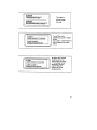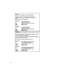
1
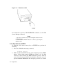
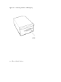
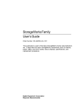
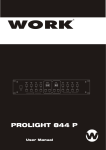
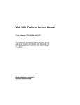
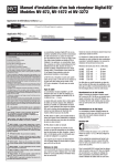
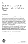
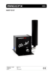
RWZ01 Magneto–Optical Disk Subsystem digi tal User’s Guide Part Number: EK–RWZ01–UG–002 RWZ01 Magneto–Optical Disk Subsystem User’s Guide Part Number: EK–RWZ01–UG–002 Prepared by U.S. Area EIC Documentation Services Digital Equipment Corporation • Merrimack, NH 03054 June 1991 The information in this document is subject to change without notice and should not be construed as a commitment by Digital Equipment Corporation. Digital Equipment Corporation assumes no responsibility for any errors that may appear in this document. The software described in this document is furnished under a license and may be used or copied only in accordance with the terms of such license. No responsibility is assumed for the use or reliability of software on equipment that is not supplied by Digital Equipment Corporation or its affiliated companies. Restricted Rights: Use, duplication, or disclosure by the U.S. Government is subject to restrictions as set forth in subparagraph (c)(1)(ii) of the Rights in Technical Data and Computer Software clause at DFARS 252.227-7013. Copyright ©1991 by Digital Equipment Corporation. All Rights Reserved. Printed in Japan The postpaid READER’S COMMENTS form on the last page of this document requests the user’s critical evaluation to assist in preparing future documentation. The following are trademarks of Digital Equipment Corporation DEC VAXBI VT DECUS DECstation VAXcluster PDP VAXELN VAXstation VAX VMS ULTRIX The DIGITAL Logo This document was prepared using VAX DOCUMENT, Version 2.0. iii This apparatus complies with the Class A limits for radio noise emissions set out in Radio Interference Regulations of Canada. iv This device complies with the standard of Information Device Wave Failure Self−Regulation Association (VCCI) to prevent wave failure occuring in the Type 1 information devices (information devices used in the commerical and industrial areas). Therefore, if the device is used in a location adjacent to residential areas, reception problems may occur in radio or television receivers. The device must be handled correctly according to the manual. v Für Bundesrepublik Deutschland und Berlin (West) For Federal Republic of Germany and West Berlin Pour la République féderale d’Allemagne et Berlin Ouest Bescheinigung des Herstellers/Importeurs Hiermit wird bescheinigt, daß die Einrichtung in Übereinstimmung mit den Bestimmungen der DBP-Verfügung 1046/84, Amtsblatt Nr. 163/1984, und Grenzwertklasse "B" der VDE0871, funkenstört ist. Der Deutschen Bundespost (DBP) wurde das Inverkehrbringen dieses Gerätes angezeigt und die Berechtigung zur Überprüfung der Serie auf Einhaltung der Bestimmungen eingeräumt. Betreiberhinweis Wir sind verpflichtet, Sie auf folgende Fakten hinzuweisen (DBP-Verfügung 1046/84, §2, Abschnitt 5): Das Gerät wurde funktechnisch sorgfältig entstört und geprüft. Beim Zusammenschalten mit anderen EDV-Geräten können im ungünstigsten Fall Funkstörungen entstehen, die dann im Einzelnen zusätzliche Funkenstörungs-Maßnahmen durch den Benutzer erfordern. Externe Datenkabel Sollte ein Austausch der von Digital spezifizierten Datenkabel nötig werden, muß der Betreiber für eine einwandfreie Funkentstörung sicherstellen, daß Austauschkabel im Aufbau und Abschirmqualität dem Digital Originalkabel entsprechen. vi vii viii Contents Preface xiii Chapter 1 Overview 1.1 1.2 1.3 1.4 1.5 1.6 Features . . . . . . . . . . . . . . . . . . . . . . . . . . . . . . . . . . . . . . . . . . . . . 1–1 System Configuration . . . . . . . . . . . . . . . . . . . . . . . . . . . . . . . . . . . 1–2 RWZ01 External Components . . . . . . . . . . . . . . . . . . . . . . . . . . . . 1–2 1.3.1 Front . . . . . . . . . . . . . . . . . . . . . . . . . . . . . . . . . . . . . . . . 1–3 1.3.2 Rear . . . . . . . . . . . . . . . . . . . . . . . . . . . . . . . . . . . . . . . . . 1–4 Cautions on Use . . . . . . . . . . . . . . . . . . . . . . . . . . . . . . . . . . . . . . . 1–5 Laser Radiation . . . . . . . . . . . . . . . . . . . . . . . . . . . . . . . . . . . . . . . 1–7 Disk . . . . . . . . . . . . . . . . . . . . . . . . . . . . . . . . . . . . . . . . . . . . . . . . 1–7 1.6.1 Data Protect Switch (Tab) . . . . . . . . . . . . . . . . . . . . . . . . 1–7 1.6.2 Condensation . . . . . . . . . . . . . . . . . . . . . . . . . . . . . . . . . . 1–8 1.6.3 Disk Maintenance . . . . . . . . . . . . . . . . . . . . . . . . . . . . . . 1–8 Chapter 2 Installation 2.1 2.2 2.3 2.4 Unpacking the RWZ01 . . . . . . . . . . . . . . . . . . . . . . . . . . . . . . . . . . 2–1 Connections . . . . . . . . . . . . . . . . . . . . . . . . . . . . . . . . . . . . . . . . . . 2–3 Checking a SCSI ID Number . . . . . . . . . . . . . . . . . . . . . . . . . . . . . 2–4 2.3.1 Operation for VMS . . . . . . . . . . . . . . . . . . . . . . . . . . . . . . 2–4 2.3.2 Operation for ULTRIX . . . . . . . . . . . . . . . . . . . . . . . . . . . 2–5 Setting Switchpack Switches . . . . . . . . . . . . . . . . . . . . . . . . . . . . . 2–5 2.4.1 Setting a SCSI ID number . . . . . . . . . . . . . . . . . . . . . . . . 2–8 ix 2.5 2.6 Changing the /etc/disktab File (ULTRIX) . . . . . . . . . . . . . . . . . . . 2–10 Creating the Special File (ULTRIX) . . . . . . . . . . . . . . . . . . . . . . . 2–10 Chapter 3 Operation 3.1 3.2 3.3 3.4 3.5 Applying Power . . . . . . . . . . . . . . . . . . . . . . . . . . . . . . . . . . . . . . . 3–1 Inserting and Initializing a Disk . . . . . . . . . . . . . . . . . . . . . . . . . . 3–2 3.2.1 For VMS Operation . . . . . . . . . . . . . . . . . . . . . . . . . . . . . 3–2 3.2.2 Operation for ULTRIX . . . . . . . . . . . . . . . . . . . . . . . . . . . 3–4 Mounting a Disk . . . . . . . . . . . . . . . . . . . . . . . . . . . . . . . . . . . . . . 3–4 3.3.1 Operation for VMS . . . . . . . . . . . . . . . . . . . . . . . . . . . . . . 3–4 3.3.2 Operation for ULTRIX . . . . . . . . . . . . . . . . . . . . . . . . . . . 3–4 Dismounting and Removing a Disk . . . . . . . . . . . . . . . . . . . . . . . . 3–5 3.4.1 Operation for VMS . . . . . . . . . . . . . . . . . . . . . . . . . . . . . . 3–5 3.4.2 Operation for ULTRIX . . . . . . . . . . . . . . . . . . . . . . . . . . . 3–6 Turning off the RWZ01 . . . . . . . . . . . . . . . . . . . . . . . . . . . . . . . . . . 3–7 Chapter 4 How to Handle Failures Appendix A Specifications A.1 A.2 Specifications of the RWZ01 . . . . . . . . . . . . . . . . . . . . . . . . . . . . . A–1 Specifications of the Disk . . . . . . . . . . . . . . . . . . . . . . . . . . . . . . . A–3 Appendix B Parts List Appendix C Regulations C.1 C.2 Safety . . . . . . . . . . . . . . . . . . . . . . . . . . . . . . . . . . . . . . . . . . . . . . C–1 EMC . . . . . . . . . . . . . . . . . . . . . . . . . . . . . . . . . . . . . . . . . . . . . . . C–1 Index x Figures 1 1–1 1–2 1–3 1–4 2–1 2–2 2–3 2–4 2–5 2–6 3–1 3–2 3–3 4–1 The RWZ01 Disk Drive . . . . . . . . . . . . . . . . . System Configuration Using VAXstation 3100 Front of RWZ01 Disk Drive . . . . . . . . . . . . . . Rear of RWZ01 Disk Drive . . . . . . . . . . . . . . . Disk Data Protection Switch (Tab) . . . . . . . . . RWZ01 Packing List . . . . . . . . . . . . . . . . . . . Connecting the RWZ01 Disk Drive . . . . . . . . . Setting the RWZ01 Switchpack Switches . . . . When a Terminator is Used . . . . . . . . . . . . . . When a Terminator is not Used . . . . . . . . . . . Setting the SCSI ID Number . . . . . . . . . . . . . Applying Power . . . . . . . . . . . . . . . . . . . . . . . Inserting a Disk . . . . . . . . . . . . . . . . . . . . . . . Removing a Disk . . . . . . . . . . . . . . . . . . . . . . Removing a Disk In An Emergency . . . . . . . . . . . . . . . . . . . . . . . . . . . . . . . . . . . . . . . . . . . . . . . . . . . . . . . . . . . . . . . . . . . . . . . . . . . . . . . . . . . . . . . . . . . . . . . . . . . . . . . . . . . . . . . . . . . . . . . . . . . . . . . . . . . . . . . . . . . . . . . . . xx . 1–2 . 1–3 . 1–4 . 1–7 . 2–2 . 2–3 . 2–5 . 2–6 . 2–7 . 2–8 . 3–2 . 3–3 . 3–6 . 4–4 Notes, Cautions, Warnings - Documentation Cautions, Warnings - Safety . . . . . . . . . . . . . SCSI ID Number Switch Settings . . . . . . . . Problem Solving . . . . . . . . . . . . . . . . . . . . . . RWZ01 Parts List . . . . . . . . . . . . . . . . . . . . SCSI Cable List . . . . . . . . . . . . . . . . . . . . . . Power Cords List . . . . . . . . . . . . . . . . . . . . . . . . . . . . . . . . . . . . . . . . . . . . . . . . . . . . . . . . . . . . . . . . . . . . . . . . . . . . . . . . . . . . . . xv . . xv . 2–9 . 4–1 B–1 B–2 B–2 Tables 1 2 2–1 4–1 B–1 B–2 B–3 xi . . . . . . . Preface This manual describes the installation and operation of the RWZ01 Magneto-Optical Disk Drive (hereafter called RWZ01 Disk Drive or RWZ01) and the actions to be taken if failures occur. Document Structure Chapter 1, Overview - Describes the functions, names of parts, and cautions on use of the RWZ01. Chapter 2, Installation - Describes the installation procedure of the RWZ01. Chapter 3, Operation - Describes how to operate the RWZ01 and how to handle disks. Chapter 4, How to Handle Failures - Describes the actions to be taken if a failure occurs in the RWZ01. Appendix A, Specifications RWZ01, disks, and attachments. Describes the specifications of the Appendix B, Parts List - Provides a list of disks, attachments, and products sold separately for the RWZ01. Appendix C, Regulations - Provides a list of the safety and EMC regulations to which the RWZ01 complies. xiii How to Use This Manual To install the RWZ01, read Chapters 1 and 2. To use the RWZ01, read Chapter 3. Refer to Chapter 4 if problems occur during installation or operation. Intended Audience This manual is intended for users of the RWZ01. Related Documentation The following related manuals are available for the RWZ01. Refer to the manuals as required. • Lens Cleaning Cartridge User’s Manual Provided with a lens cleaning cartridge kit. • RWZ01 Magneto-Optical Disk Subsystem Technical Manual The following manuals provide additional information on the environment in which the RWZ01 is used, and may help your understanding of this manual. • Owner’s Manual/User’s Guide of each host computer • VMS User’s Manual • VMS System Manager’s Manual • ULTRIX Guide to Disk Maintenance • ULTRIX Reference Volume. • VMS Version 5.3 Small Computer System Interface (SCSI) Device Support Manual xiv Conventions The following conventions are used in this publication: Table 1: Notes, Cautions, Warnings - Documentation NOTE Calls the attention to any item of information that may be of special importance to the reader. CAUTION Contains essential information to avoid damage to the equipment. WARNING Contains essential information for the safety of the user. Table 2: Cautions, Warnings - Safety DANGER Serious injury or death is imminent if you continue in this direction. WARNING Injury is imminent if you continue in this direction. CAUTION Injury is possible if you continue in this direction. ATTENTION (NOTE) Damage to the equipment can occur if you continue in this direction. xv Precautions Safety • The unit operates on 100-120 Vac, 50/60 Hz in the U.S.A. and Canada, or 220-240 Vac, 50/60 Hz in the European countries. • Do not share the ac outlet with any other power-consuming equipment such as copying machines or shredders. • To disconnect the cord, pull it out by the plug. Never pull the cord itself. • Unplug the unit from the wall outlet if it will not be used for an extended period of time. Installation • Do not drop or bump the unit against other objects. • Do not place the unit in a location subject to vibration or on an unstable base. • The unit is designed to be positioned horizontally. • Do not install the unit near heat sources such as radiators or air ducts, or in a place subject to direct sunlight, excessive dust and/or moisture. • Provide adequate air circulation to prevent internal heat build-up. • The unit uses high-frequency radio signals and may cause interference to radio or TV reception. Should this occur, separate the equipment. Operation • If the unit is brought directly from a cold to a warm location, moisture may condense inside the unit. In this case, allow more than one hour before turning it on. Inserting a disk while condensed moisture is present may damage the unit and/or the disk. Remove the disk immediately if there is any sign of moisture condensation. Leave the RWZ01 on after removing the disk, this helps the moisture evaporate. • Do not move the unit with the disk in the drive. Be sure to take out the disk if it will not be used for an extended period of time. xvi Maintenance • Clean the cabinet with a soft dry cloth, or a soft cloth lightly moistened with a mild detergent solution. Do not use any type of solvent, such as alcohol or benzine, as this may damage the finish. xvii Zur besonderen Beachtung Zur Sicherheit • Das Gerät ist für Betrieb an 100-120 V Wechselspannung, 50/60 Hz (USA und Kanada) bzw. 220-240 V Wechselspannung (Europa) bestimmt. • Schließen Sie an die Steckdose nicht gleichzeitig ein anderes Gerät mit hoher Leistungsaufnahme (zB. Kopierer, Reißwolf). • Fassen Sie zum Abziehen des Kabels stets am Stecker und niemals am Kabel selbst an. • Trennen Sie das Laufwerk bei längerer Nichtverwendung von der Wandsteckdos ab. Zur Aufstellung • Stellen Sie das Laufwerk so auf, daß es nicht herunterfallen kann und keinen Stößen ausgesetzt ist. • Stellen Sie das Laufwerk nicht an Plätze, die Vibrationen ausgesetzt ober unstabil sind. • Das Laufwerk ist für horizontalen Betrieb bestimmt. • Stellen Sie das Laufwerk nicht in die Nähe von Wärmequellen wie Heizungen oder Warmluftauslässen und auch nicht in die Nähe von Plätzen, die prallem Sonnenlicht, starker Staubentwicklung und /oder Feuchtigkeit ausgesetzt sind. • Achten Sie auf ausreichende Luftzirkulation, um einen internen Hitzestau zu vermelden. • Das Laufwerk strahlt Hochfrequenzsignale aus, die den Radio- oder TV-Empfang stören können. Stellen Sie in einem solchen Fall die Geräte weiter voneinander entfernt aus. Zum Betrieb • Wenn das Laufwerk direkt von einem kalten an einen warmen Ort gebracht oder an einem feuchten Ort betrieben wird, kann sich Kondenswasser im Inneren bilden. Warten Sie in einem solchen Fall etwa eine Stunde, bevor Sie das Gerät einschalten. Wenn beim Einlegen der Platte noch Kondenswasser im Inneren vorhanden ist, kann hierdurch das Laufwerk und/oder die Platte beschädigt werden. Bei Anzeichen von Feuchtigkeit nehmen Sie xviii die Platte sofort heraus und lassen Sie das Laufwerk eingeschaltet, damit die Feuchtigkeit schneller verdunstet. • Nehmen Sie die Platte stets heraus, wenn das Gerät transportiert oder längere Zeit nicht verwendet wird. Zur Wartung • Reinigen Sie das Gehäuse mit einem trockenen, weichen oder mit einem trockenen, leicht mit mildem Haushaitsreiniger angefeuchteten Tuch. Alle Arten von Lösungsmittel wie Alkohol oder Benzin dürfen nicht verwendet werden, da sie das Finish angreifen. xix Figure 1: The RWZ01 Disk Drive xx Chapter 1 Overview This chapter contains an overview of the features and functions of the RWZ01 Disk Drive (see Figure 1) and provides cautions on its use. 1.1 Features The RWZ01 Disk Drive is an external storage device that uses large capacity removable disks and has the following features: • A write/read disk using magneto-optical recording with a multiple write capability. • A large capacity disk (590 MB, 512 bytes/sector, excluding alternate areas). • A disk format that complies with the Continuous/Composite Servo (CS) format (ISO/IEC DIS 10089) of International Standard Organization (ISO), which is the world standard. • A Small Computer System Interface (SCSI) which complies with ANSI X3.131-1986, CCS Rev.4B. Up to eight units, including the host computer, can be connected to one SCSI bus. • A high-speed transmission of data using a 2400 rpm spindle motor. Overview 1–1 • A fast seek time of 95 ms using the thin, light-weight optical pick-up. • An error correction using Long Distance Code. 1.2 System Configuration The RWZ01 is Small Computer System Interface (SCSI) compatible and therefore can be connected to the host computer SCSI bus or to any SCSI unit in the system. Figure 1-1 shows a system configuration with a VAXstation 3100 as the host computer. Figure 1–1: System Configuration Using VAXstation 3100 A SCSI terminator (terminal resistance) is built into the RWZ01 Disk Drive. With this, the RWZ01 can be connected as either an intermediate or terminating device. When the RWZ01 is the last device (terminating device) on the SCSI bus, set switches 3 and 4 to ENABLE (see Section 2.4, Setting Switchpack Switches). 1.3 RWZ01 External Components The following sections describe the external components on the front and the rear of the RWZ01. 1–2 Overview 1.3.1 Front The names and functions of the parts on the front of the RWZ01 are (see Figure 1-2): Figure 1–2: Front of RWZ01 Disk Drive 1. Power supply indicator This indicator is lit when power is on. 2. BUSY indicator This indicator is lit when data is being read or written to the disk. 3. Disk insertion entrance This is where you insert a disk (see Figure 3-2). 4. Air intake duct for cooling This duct takes in air to cool the interior. 5. Emergency eject hole This is used for emergency ejection of a disk (see Chapter 4, How to Handle Failures). 6. EJECT button This is the button to press when removing a disk from the RWZ01. Overview 1–3 1.3.2 Rear The names and functions of the components on the rear of the RWZ01 are described in the following (see Figure 1-3). See Chapter 2 for a description of the use of these components. Figure 1–3: Rear of RWZ01 Disk Drive 1. Interface connector This is the connecting point of the RWZ01 to the SCSI bus. Use a SCSI cable (sold separately) to connect to the host computer or other SCSI unit (see Section 2.2, Connections). 2. Switchpack Switches This set of switches controls the operation of the RWZ01 and its SCSI ID number (see Section 2.4, Setting Switchpack Switches). 3. Air exhaust duct for heat release This is the cooling air exhaust duct. 4. F.GND pin This F.GND pin is not used by the RWZ01 because a 3-pin (with ground) power cable is used. 1–4 Overview 5. AC Input Power Connector This connects to the ac input supply with the 3-pin (with ground) power cable. 6. AC Power Switch This switch turns the ac power on or off. 1.4 Cautions on Use Note the following points to use the RWZ01 safely. • AC Input Power — Use 100 to 120 Vac, 50/60 Hz supply voltage for USA, Japan, and Canada. Use 220 to 240 Vac, 50/60 Hz supply voltage for European countries. — Do not connect to an ac power line that includes a large power consumption device such as a copier or shredder. • Shock and vibration The RWZ01 is susceptible to damage from shock or vibration. • Installation location Operate the RWZ01 in the horizontal position. A failure may occur when it is not operated in the horizontal position. Do not operate or store the RWZ01 in locations with the following conditions (see Appendix A, Specifications): — Severe temperatures changes — Direct sunlight — Strong magnetic field or gas — Electrostatic or noise discharges — High humidity — Dust • Airflow Do not place the RWZ01 in a location with poor airflow. Do not cover the cooling air intake or exhaust ducts. Overview 1–5 • Condensation — Avoid sudden temperature change to avoid condensation. — Remove a disk as soon as condensation is suspected. To remove condensation within the unit turn the RWZ01 power on without inserting a disk. • Moving Do not move the RWZ01 during operation because the disk is rotating at a high speed and may be damaged. Stop the operation, remove the disk and then move the RWZ01. • Handling failure If a failure occurs, remove the ac power cable from the power source and contact the Digital Equipment Corporation service representative. • Cleaning an optical head Dirt on the lens of the optical head can cause a read or write error. Clean the lens once a month using a lens cleaning cartridge. See Chapter 4 for information on using a lens cleaning cartridge. Notes 1. Use an RWX1K-01 disk with the RWZ01. 2. Execute the DISMOUNT (unmount) command before removing a disk (see Section 3.4, Dismounting and Removing a Disk). Removing a disk while data is being written to the disk interrupts the operation. 3. In the RWZ01, new data is written after old data is erased. Therefore, the time required for reading is different from that required for writing. 1–6 Overview 1.5 Laser Radiation The RWZ01 Disk Drive is a Class 1 laser product. Since the laser beam is completely enclosed, no harmful light is emitted during operation or normal maintenance. However, when any operation or adjustment is performed outside of the methods specified in this manual, exposure to dangerous laser emissions may occur. 1.6 Disk The RWZ01 treats each side of the disk as a separate volume (file area). Use side A and side B of a disk as separate volumes. The disk is inserted with the label of the side used facing up. 1.6.1 Data Protect Switch (Tab) The DATA PROTECT (red) switch (see Figure 1-4) on the disk prevents the inadvertent writing of data. To write protect the disk, move the red switch in the direction of the arrow. To write enable the disk, move the red switch in the opposite direction of the arrow. Figure 1–4: Disk Data Protection Switch (Tab) Overview 1–7 1.6.2 Condensation Do not use the disk in a location with great temperature variation or high humidity—condensation may prevent the writing and reading of data. 1.6.3 Disk Maintenance Use the following guidelines for proper disk maintenance. • Store disks in the plastic case provided. • Do not store disks in a dusty area, in direct sunlight, near a heater, or in a humid area. • Do not place disks on a dashboard or tray in a car. • Do not place disks in a location affected by strong magnetic fields or volatile gas. • Do not leave a disk inside the drive unit when not being used. 1–8 Overview Chapter 2 Installation This chapter contains the RWZ01 installation procedure. 2.1 Unpacking the RWZ01 The RWZ01 is delivered in a single carton. Open the carton and check the contents against Figure 2–1. If any parts are missing or damaged, contact your local Digital representative, transport agency, or distributor. Installation 2–1 Figure 2–1: RWZ01 Packing List 2–2 Installation 2.2 Connections Figure 2–2 shows the cable connections to be made and the switchpack switches to be set, for installing the RWZ01. Figure 2–2: Connecting the RWZ01 Disk Drive Installation 2–3 When the RWZ01 is connected to the host computer SCSI bus the side of the RWZ01 connected to the cable is automatically the SCSI IN connector and the other side is the SCSI OUT connector. To connect the RWZ01 Disk Drive to the SCSI bus, perform the following: 1. Disconnect power to the host computer and the RWZ01. Notes 1. Up to eight SCSI devices, including the host computer, can be connected to one SCSI bus. 2. The total cable length connecting the SCSI devices on a SCSI bus cannot exceed 6 m. 2. Make sure that the SCSI ID for the RWZ01 is unique for that SCSI bus (see Section 2.4, Setting Switchpack Switches). 3. If the RWZ01 is the last SCSI device on the SCSI bus, set the switches of the TERMINATOR and TERMINATOR POWER switches to ENABLE (see Section 2.4, Setting Switchpack Switches). 4. Connect the SCSI cable to the connector and secure it with the connector latches (wire loops). 2.3 Checking a SCSI ID Number Check to ensure that the SCSI ID number set by the switchpack switches is recognized by the host computer. The following sections have examples for VMS and ULTRIX operating systems. In these examples, the SCSI ID number is set to 3 of the SCSI bus (external bus). See the host computer manual for a description of the SCSI bus. 2.3.1 Operation for VMS For VMS systems, use the console command mode SHOW DEVICES command. >>> SHOW DEVICES The system will display a list of the devices connected to the host and their ID numbers. If the RWZ01 is not displayed with the SCSI ID number that was set, set the SCSI ID number of the RWZ01 again. First turn off the ac power to all the devices on the SCSI bus. 2–4 Installation 2.3.2 Operation for ULTRIX Confirm the connected device. See the appropriate ULTRIX System Manual for the console command. 2.4 Setting Switchpack Switches Switches 1 through 5 DISABLE (up) or ENABLE (down) the RWZ01 functions they control. Switches 6 through 8 set to 1 (up) or 0 (down) to set the SCSI ID number of the RWZ01 (see Figure 2-3). If the RWZ01 is connected to the SCSI bus, disconnect the ac power to all the SCSI devices on that SCSI bus before changing the switch settings. When delivered from the factory, switches 1 through 3 and 5 are set to ENABLE (down) and switch 4 is set to DISABLE (up). The functions of switches 1 to 5 are described in the following: Figure 2–3: Setting the RWZ01 Switchpack Switches 1. AUTO SPIN UP (1) - The default is ENABLE. When enabled, this switch sets the spindle motor (motor that rotates the disk) so that it rotates automatically when you insert a disk. Installation 2–5 2. MANUAL EJECT (2) - The default is ENABLE. When enabled, this switch enables the EJECT button for removing a disk. 3. TERMINATOR POWER (3) - The default is ENABLE (the RWZ01 is the terminating SCSI bus device). This switch controls whether the RWZ01 or some external device supplies SCSI power to the SCSI terminator. (If the built-in RWZ01 terminator is used, an external SCSI terminator is not required.) When the RWZ01 is the terminator unit, it supplies power to the SCSI terminator. • Set the switch to ENABLE when the RWZ01 is the terminating unit (see Figure 2–4). Figure 2–4: When a Terminator is Used 2–6 Installation • Set the switch to DISABLE when the RWZ01 is not the terminating unit (see Figure 2–5). Figure 2–5: When a Terminator is not Used 4. TERMINATOR - Default is DISABLE This switch controls the use of the RWZ01 built-in terminator. • When the RWZ01 is the terminating unit (see Figure 2–4), set the switch to ENABLE. • When the RWZ01 is not the terminating unit (see Figure 2–5), set the switch to DISABLE. 5. PARITY - Default is ENABLE. When set to ENABLE, the RWZ01 performs parity checking. This switch must be set to ENABLE. Installation 2–7 2.4.1 Setting a SCSI ID number Use the three ID SELECT switches (6 through 8) to set the SCSI ID number (0 through 7) of the RWZ01. For these switches, up (ID SELECT) is on ( | ) and down is off (0) (see Figure 2-6). When delivered from the factory, the SCSI ID number is set to 0 (switches 6, 7, and 8 down). The switch settings for the allowable SCSI ID numbers are shown in Table 2-1. Figure 2–6: Setting the SCSI ID Number 2–8 Installation Table 2–1: SCSI ID Number Switch Settings SCSI ID number ID SELECT switch position 4 2 1 0 OFF OFF OFF 1 OFF OFF ON 2 OFF ON OFF 3 OFF ON ON 4 ON OFF OFF 5 ON OFF ON 6 ON ON OFF 7 ON ON ON Note When you do not know which SCSI ID number to set, contact your system manager. Installation 2–9 2.5 Changing the /etc/disktab File (ULTRIX) 1. Type in the following command. # grep rwz01 /etc/disktab 2. If the following message is displayed, skip the next step . rwz01|RWZ01|DEC RWZ01 Removal:\ 3. Add the following field to "/etc/disktab". # MO disk drives (RWZ01) rwz01|RWZ01|DEC RWZ01 Removal:\ :ty=removal:ns#31:nt#10:nc#1862:\ :pa#32768:ba#8192:fa#1024:\ :pb#131072:bb#4096:fb#1024:\ :pc#576999:bc#8192:fc#1024:\ :pg#413159:bg#8192:fg#1024: 2.6 Creating the Special File (ULTRIX) With the ULTRIX operating system, use the MAKEDEV(8) shell script to create a special file for the RWZ01. The following example shows how to create the special file with a SCSI ID of 3. # cd /dev # MAKEDEV rz3 For more information on special file, see special file(4) in the ULTRIX Reference Pages. 2–10 Installation Chapter 3 Operation This chapter describes how to operate the RWZ01 and the disks. 3.1 Applying Power To apply power to the RWZ01, press the ac power switch (see Figure 3–1). 1. The ac POWER indicator lights. 2. Boot (activate) the host computer (see the host computer manual). Operation 3–1 Figure 3–1: Applying Power 3.2 Inserting and Initializing a Disk Before using a new disk, you must first initialize the disk. The following example shows how to initialize a disk when the RWZ01, with a SCSI ID of 1, is connected to the SCSI Bus using VMS and ULTRIX. 3.2.1 For VMS Operation 1. Insert a disk into the RWZ01 (see Figure 3–2). 3–2 Operation Figure 3–2: Inserting a Disk 2. Enter the INITIALIZE command. $ INITIALIZE DKB100 (volume label) Where: DK is the disk, B is SCSI port B, 100 is the SCSI ID (1), and (volume label) is the appropriate volume label. See the VMS User’s Manual for more information about the INITIALIZE command. Notes 1. The RWZ01 treats each side of the disk (A and B) as separate volumes. 2. When a disk is initialized, the contents of the disk are lost. 3. Specify the SCSI ID number as the number set by switchpack switches 6, 7, and 8. Operation 3–3 3.2.2 Operation for ULTRIX 1. Insert a disk in the RWZ01 (see Figure 3–2). 2. Initialize a disk using the newfs(8) command. # newfs /dev/rrz1c rwz01 For information about the ULTRIX newfs(8) command, see the ULTRIX Guide to Disk Maintenance. 3.3 Mounting a Disk Before using the disk, mount it on the host system. The following examples show how to mount the RWZ01 with a SCSI ID of 1 using VMS and ULTRIX. 3.3.1 Operation for VMS Enter the MOUNT command. $ MOUNT DKB100 (volume label) For information about the VMS MOUNT command, see the VMS System Manager’s Manual. Notes 1. The RWZ01 treats side A and side B of the disk as separate volumes. 2. Specify the number set by the switchpack switches for the SCSI ID number. 3.3.2 Operation for ULTRIX Enter the ULTRIX mount(8) command. # mount /dev/rz1c /mnt For information about the ULTRIX mount(8) command, see the ULTRIX Guide to Disk Maintenance. 3–4 Operation 3.4 Dismounting and Removing a Disk Make sure you dismount the disk before removing the disk from the RWZ01. In the following example the RWZ01 SCSI ID is 1 and the RWZ01 is connected to the SCSI Bus. 3.4.1 Operation for VMS To dismount a disk when connected to a VMS host, perform the following: 1. Enter the DISMOUNT command. $ DISMOUNT DKB100 2. Make sure that the BUSY indicator is off and then press the EJECT button and lift the disk from the RWZ01 (see Figure 3-3). If a disk cannot be removed when the EJECT button is pressed, turn the power off and remove the disk by inserting the emergency eject tool (provided with the RWZ01) into the emergency eject hole (see Section 4.1, How to Handle Failures). In this case, the power supply of the RWZ01 must be disconnected. Operation 3–5 Figure 3–3: Removing a Disk For information about the VMS DISMOUNT command see the VMS System Manager’s Manual. Notes 1. Specify the number set by the switchpack switches for the SCSI ID number. 2. Check that the BUSY indicator is off before pressing the EJECT button. 3.4.2 Operation for ULTRIX To dismount a disk when connected to an ULTRIX host, perform the following: 1. Enter the ULTRIX unmount(8) command. # unmount /dev/rz1c 2. Make sure that the BUSY indicator is off and then press the EJECT button. Lift the disk from the RWZ01 (see Figure 3-3). If a disk cannot be removed when the EJECT button is pressed, turn the power off and remove the disk by inserting the emergency eject tool (provided with the RWZ01) into the emergency eject hole (see Section 3–6 Operation 4.1, How to Handle Failures). In this case, the power supply of the RWZ01 must be disconnected. For more information about the ULTRIX unmount(8) command refer to the ULTRIX Guide to Disk Maintenance. 3.5 Turning off the RWZ01 To turn off the RWZ01, shut down the host computer (see the appropriate user’s manual). Do not turn off the RWZ01 until the host computer has been shut down and powered off. To turn off the RWZ01, press the ac power switch to (0). Operation 3–7 Chapter 4 How to Handle Failures This chapter describes the actions to be taken if a failure occurs in the RWZ01. When the failure cannot be corrected, contact your Digital service representative. Table 4-1 describes general failures and actions to be taken to correct them. Table 4–1: Problem Solving Problem Action to Take No power even if the power supply switch is set to ON ( | ). Make sure that the power cable is inserted in the socket correctly. A power supply indicator does not come on. Make sure that the ac power cable is inserted in the socket correctly. A disk cannot be inserted. Make sure that the disk is an RWX1K-01 or equivalent. Make sure that the disk is inserted in a correct direction. How to Handle Failures 4–1 Table 4–1 (Cont.): Problem Solving Problem Action to Take A disk cannot be removed. Make sure that switchpack switch 2 is set to ENABLE. Disconnect the ac power to the RWZ01 and remove the disk by inserting an emergency eject tool into the emergency eject hole (see Figure 4-1). RWZ01 is not recognized by the SHOW DEVICE or test -c(rzdisk -q) command. Make sure that the SCSI cable is connected correctly (see Section 2.2, Connection). Make sure that the SCSI ID number is not duplicated with an ID number of some other SCSI device (see Section 2.4, Setting Switchpack Switches). A disk cannot be mounted. Make sure that a disk is inserted. Make sure that the disk side (side A or side B) is specified correctly. When a disk that is not initialized is mounted, the BUSY indicator stays on and a command is not terminated. In this case, remove the disk by pressing the EJECT button and then interrupt the MOUNT process. Data in the disk cannot be read. Check whether a correct disk type (P/N: RWX1K-01 or equivalent) is used. Clean the lens using a lens cleaning cartridge. A lens cleaning cartridge kit (P/N: RWX1H-AA) is available from Digital. Refer to the guide provided with the lens cleaning cartridge kit for instructions on using a lens cleaning cartridge. 4–2 How to Handle Failures Table 4–1 (Cont.): Problem Solving Problem Action to Take Data cannot be written to a disk. Check whether the disk data protection switch (tab) is set to DATA PROTECT. Make sure an RWX1K-01 disk or equivalent is used. Clean the lens using a lens cleaning cartridge. A lens cleaning cartridge kit (P/N: RWX1H-AA) is available from Digital. Refer to the guide provided with the lens cleaning cartridge kit for instructions on using a lens cleaning cartridge. A spindle motor does not rotate even if a disk is inserted. Make sure switchpack switch 1 is set to ENABLE. How to Handle Failures 4–3 Figure 4–1: Removing a Disk In An Emergency 4–4 How to Handle Failures Appendix A Specifications This appendix contains the specifications for the RWZ01 and the RWX1K disks. A.1 Specifications of the RWZ01 Model name: Magneto-Optical Disk Subsystem RWZ01-AA External measurement (excluding the highest projected part): • Width 211 mm (8.3 inch) • Depth 310 mm (11.81 inch) • Height 126 mm (4.96 inch) • Weight 6.8 kg (14.96 lbs) Environmental conditions: • Installation direction: Horizontal (within ± 5° centerline) • During operation: • Temperature: 10 to 40°C • Temperature graduation: 10°C/hour or less • Relative humidity: 10 to 90% (no condensation) • Vibration: 0.2G or less • Shock: 25G or less (3 ms half sine wave) Specifications A–1 • Non-operation: • Temperature: -30 to 60°C • Temperature graduation: 15°C/hour or less • Relative humidity: 5 to 90% (no condensation) • Vibration: 1G or less • Shock: 60G or less (3 ms half sine wave) 20G or less (28 ms rectangular wave) Electrical specification: • • Power requirements: • U.S.A. and Canada: 100 to 120 Vac, 50/60 Hz • European countries: 220 to 240 Vac, 50/60 Hz Current drain: • U.S.A. and Canada: 0.45 A max. • European countries: 0.3 A max. Storage capacity, formatted (excluding alternate areas): • Per disk: 590 MB (512 bytes/sector) • Per side: 295 MB (512 bytes/sector) Total storage capacity, unformatted: • Per disk: 867 MB • Per side: 433.5 MB Rotation: • Rotational count: 2400 rpm (CAV) • Average wait time: 12.5 ms • Bias magnet rotation speed: 18 ms (average) Seek time (rotational delay/excluding SCSI overhead): • Per track: 10 ms (average) • Short stroke: 22 ms (average) (± 64 tracks) • Average: 95 ms (1/3 full stroke) A–2 Specifications • Maximum: 185 ms Transmission speed: • Data transmission speed: 7.40 MB/s • User data transmission speed • Transmission speed: 620 KB/s • Burst transmission speed: 1.2 MB/s (maximum) Loading time: • Loading time: 6.4 s (average) • Unloading time: 3.6 s (average) Error rate: • Read error rate: Unrecoverable 1 x 10 • Seek error rate 1 x 10 5 12 times/bit times (two retries) Others: • • Laser: • Method: Semiconductor laser GaAIAs • Wave length: 785 nm • Maximum output: 30 mW Host interface: • Small Computer System Interface (SCSI) (ANSI X3.131-1986, CCS Rev.4B) A.2 Specifications of the Disk Model name: Disk RWX1K-01 (512 bytes/sector) External specifications: • Disk external diameter: 130 nm (5.12 inch) • Hub external diameter: 25 mm (0.98 inch) • Disk cartridge measurement: • Width 135 mm (5.31 inch) • Depth 153 mm (6.02 inch) Specifications A–3 • Thickness 11 mm (0.43 inch) • Weight 155 g (0.34 lbs) Environmental conditions: • • During operation: • Temperature: 10 to 50°C • Temperature graduation: 10° C/hour or less • Relative humidity: 10 to 90% (no condensation) Non-operation: • Humidity: -10 to 50°C • Temperature graduation: 15°C/hour or less • Relative humidity: 10 to 90% (no condensation) Format: • User area: 30 to 60 mm, radius, (0.12 to 0.24 inch) • Number of tracks: 18751/side • Number of sectors: 31 • Track mode: Spiral • Track pitch: 1.6 micrometer • Rotational direction: CCW Storage capacity, formatted (excludes alternate areas): • Per disk: 590 MB • Per side: 295 MB (data can be stored on both sides) Total storage capacity, unformatted: • Per disk: 867 MB • Per side: 433.5 MB A–4 Specifications Appendix B Parts List The tables in this appendix include a parts list for the RWZ01, A SCSI cable list, and a power cord list. Table B–1: RWZ01 Parts List Part name Order number Source Magneto-Optical Disk Subsystem RWZ01-AA – RWZ01 Magneto-Optical Disk Subsystem Maintenance Guide EK-RWZ01-MG – Optical disk cartridge RWX1K-01 O Lens cleaning cartridge kit RWX1H-AA O Lens Cleaning Cartridge User’s Manual EK-RWX1H-UG * Source — Part of the basic RWZ01 O Available as an option * Provided with a lens cleaning cartridge kit (P/N: RWX1H-AA)) Parts List B–1 Table B–2: SCSI Cable List Connection Order number Source MicroVAX3100 - RWZ01 VAXstation3100 - RWZ01 DECstation2100 - RWZ01 DECstation3100 - RWZ01 BC56H-03 (3 feet) O DECstation5000 - RWZ01 BC09D-03 (3 feet) * RWZ01 - RWZ01 BC19J-1E (1.5 feet) O Source — Part of the basic RWZ01 O Available as an option * Provided with the DECstation 5000. Table B–3: Power Cords List Order number Description Source BN19A-2E UK/Ireland-240 Vac O BN19C-2E Central Europe -220 Vac O BN19E-2E Switzerland-220 Vac O BN19H-2E Australia/New Zealand-240/230 Vac O BN19K-2E Denmark-220 Vac O BN19M-2E Italy-220 Vac O BN19S-2E India, South Africa-220 Vac O BN19U-2E Israel-240 Vac O Austria, Belgium, Finland, France, Germany, Holland, Norway, Portugal, Spain, Sweden Source — Part of the basic RWZ01 O Available as an option B–2 Parts List Appendix C Regulations This product meets the following safety and EMC regulations. C.1 Safety • UL478 5th Edition • UL1950 1st Edition • CSA22.2 No.220 • DHHS Laser Compliance 21 CFR Subchapter J, Class 1 • TUV Certification according to IEC380/VDE0806 • TUV Certification according to IEC950 • TUV Certification according to IEC825/VDE0837 C.2 EMC • FCC47 cfr Part15 Subpart J, Class A • DOC SOR/88-475 Class A • VDE0871(B) Class B / VDE0875 Class N • VCCI Class 1 Information Technology Equipment Regulations C–1 Index A AC input power, 1–5 AC input power connector ac input supply, 1–5 function of, 1–5 location of, 1–5 AC POWER indicator, 3–1 AC power switch, 3–1 function of, 1–5 location of, 1–5 Air exhaust duct function of, 1–4 location of, 1–4 Air intake duct function of, 1–3 location of, 1–3 Airflow, 1–5 Applying power, 3–1 AUTO SPIN UP, 2–5 B BUSY indicator function of, 1–3 location of, 1–3 C Cautions condensation, 1–6 installation location, 1–5 laser radiation, 1–7 moving, 1–6 shock and vibration, 1–5 Cleaning lens, 1–6, 4–2, 4–3 Condensation, 1–6 Connections See also System configuration SCSI IN connector, 2–4 SCSI OUT connector, 2–4 setting switchpack switches, 2–3 to SCSI bus, 2–4 with SCSI cable, 2–4 Cooling air exhaust duct, 1–4 air intake duct, 1–2 airflow, 1–5 exhaust ducts, 1–5 D Data protect switch, location of, 1–7 Disk dismounting of, 3–5 emergency ejection of, 1–3 emergency removal of, 4–2 Index–1 Disk (cont’d) environmental conditions, A–4 external specifications, A–3 format, A–4 initialization of, 3–2 maintenance of, 1–8 mounting of, 3–4 protection of, 1–7 removal of, 3–5, 3–6 rotation specification, A–2 seek time specification, A–2 separate volumes of, 1–7 side A, 1–7, 3–3, 3–4, 4–2 side B, 1–7, 3–3, 3–4, 4–2 storage capacity, A–2, A–4 Disk insertion entrance function of, 1–3 location of, 1–3 Dismounting a disk ULTRIX operation, 3–6 VMS operation, 3–5 E EJECT button, 3–5 function of, 1–3 location of, 1–3 Electrical specification, A–2 EMC regulations, C–1 Emergency eject hole, 3–5, 3–6, 4–2 function of, 1–3 location of, 1–3 Emergency eject tool, 3–6, 4–2 Environmental conditions, A–1 Environmental conditions, disk, A–4 Error rate, A–3 External components, 1–2 to 1–5 External measurement, A–1 External specifications, disk, A–3 Index–2 F F.GND pin function of, 1–4 location of, 1–4 Failures, 1–6, 4–1 to 4–4 Format, disk, A–4 I Initializing a disk, 3–2 ULTRIX operation, 3–4 VMS operation, 3–2 Installation location, 1–5 Interface connector function of, 1–4 location of, 1–4 L Laser beam, 1–7 Laser radiation, 1–7 Lens, cleaning of, 1–6, 4–2, 4–3 Loading time, A–3 M MANUAL EJECT, 2–6 Mounting a disk ULTRIX operation, 3–4 VMS operation, 3–4 Moving, 1–6 O Optical head, 1–6 cleaning of, 1–6 P PARITY, 2–7 Parts list, B–1 Power connector See AC input power connector Power cord list, B–2 Power requirements See Electrical specification Power supply indicator function of, 1–3 location of, 1–3 Power, applying, 3–1 Problem solving See Failures R Regulations, C–1 EMC, C–1 safety, C–1 Removing a disk EJECT button, 1–3, 3–5 emergency eject hole, 3–5 emergency ejection, 1–3, 3–6, 4–2 Rotation of disk, A–2 S Safety regulations, C–1 SCSI See also System configuration bus of, 1–2, 1–4 cable list, B–1 checking ID number, 2–4 compatibility of, 1–2 ID number of, 1–4 interface of, 1–2 setting ID number, 2–5, 2–8 setting ID SELECT, 2–8 terminator of, 1–2 SCSI ID, setting of, 2–5 duplication of, 4–2 ULTRIX operation, 2–10 VMS operation, 2–4 Seek time of disk, A–2 Shock and vibration, 1–5 Storage capacity formatted, A–2, A–4 unformatted, A–2, A–4 Switchpack switches factory default settings, 2–5 function of, 1–4, 2–5 to 2–6 location of, 1–4 setting of, 2–5 setting SCSI ID number, 2–5 System configuration interface connector, 1–4 SCSI bus, 1–2 SCSI compatible, 1–2 SCSI interface, 1–2 SCSI terminator, 1–2 T TERMINATOR, 2–7 setting switches, 2–4 TERMINATOR POWER, 2–6 setting switches, 2–4 Transmission speed, A–3 U ULTRIX unmount(8), 3–7 V VMS DISMOUNT, 3–6 W Write enable See Data protect Write protect See Data protect Index–3 digi tal Printed in Japan